

Page 1
www.fetco.com
User’s Guide
Model TBS-21A
f Iced Tea Brewer
f Iced Tea / Coffee Brewer
Table of Contents
Contact Information ..................................................2
Specifications............................................................2
Versions ................................................................2
Requirements........................................................2
Weights and Capacities ........................................2
Electrical Configuration and Brewing Efficiency ...2
Dimensions & Utility Connections .........................3
Installation................................................................. 4
Operating Procedures ..............................................6
Programming ............................................................7
Batch Settings – Iced Tea Only Version ...............7
FETCO® and EXTRACTOR® are trademarks or trade names of Food Equipment Technologies Company.
© 2005 Food Equipment Technologies Company Part # P014 March 16, 2005
Batch Settings – Iced Tea / Coffee Version..........8
Temperature Settings ...........................................8
Diagnostics ...........................................................8
Relay Test .............................................................9
Error Codes........................................................... 9
Wiring Diagram.......................................................10
Cleaning & Maintenance ........................................11
Dispenser Parts ...................................................... 12
Brewer Parts ...........................................................14
Page 2
Contact Information
FETCO
®
Food Equipment Technologies Company
600 Rose Road
Lake Zurich • IL • 60047-0429 • USA
Internet: www.fetco.com
Phone: (800) 338-2699 (US & Canada)
(847) 719-3000
Fax: (847) 719-3001
Email: sales@fetco.com
techsupport@fetco.com
Specifications
Versions
The TBS-21A is available in two versions, determined by the software and the start switch configuration:
f Iced Tea Only version – Start switch is selectable between “FULL” or “HALF” batches.
f Iced Tea / Coffee version – Start switch is selectable between “ICED TEA” or “COFFEE”.
Requirements
f Water Requirements: f Electrical: See electrical configuration chart.
20-75 psig, 1.5 gpm
Cold water only
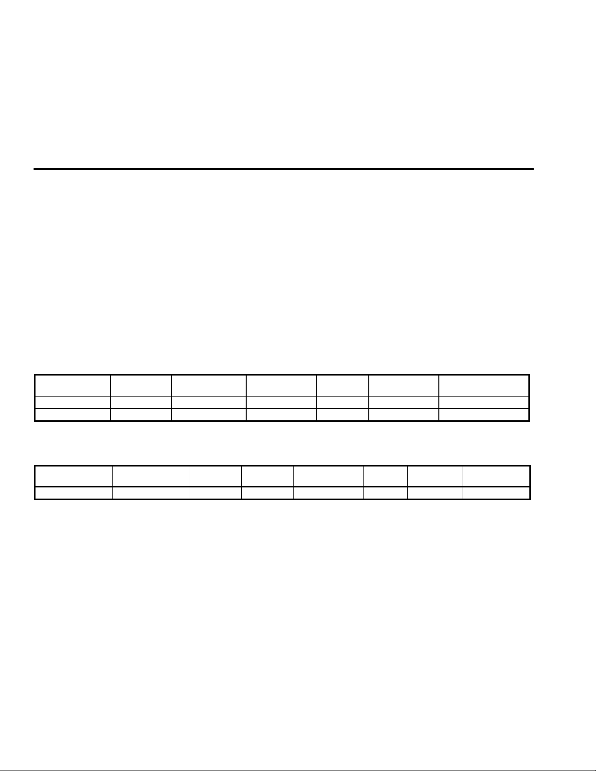
Weights and Capacities
Brewer Weight
(empty)
40.0 lbs. 2.3 gal. 59.1 lbs. 11.0 lbs. 3.0 gal. 36.0 lbs. 95.1 lbs.
18.1 kg 8.7 liters 26.8 kg 5.0 kg. 11.3 liters. 16.3 kg. 43.1 kg.
Water Tank
Capacity
Brewer Weight
(filled)
Weight (empty)
Electrical Configuration and Brewing Efficiency
Electrical Heater Voltage Maximum
Config. Code Configuration (AC) Phase Wires KW Amp draw
E21016 1 X 2.1KW 120 single 2 + ground 2.2 18.0 6
f Paper Filters: 15” X 5 ½ ” Product # F001
Dispenser
Dispenser
Capacity
**Batches per hour are based on standard factory settings.
Dispenser
Weight (filled)
Total Weight Brewer
& Dispenser Filled
Batches
Per Hour**
2
Page 3
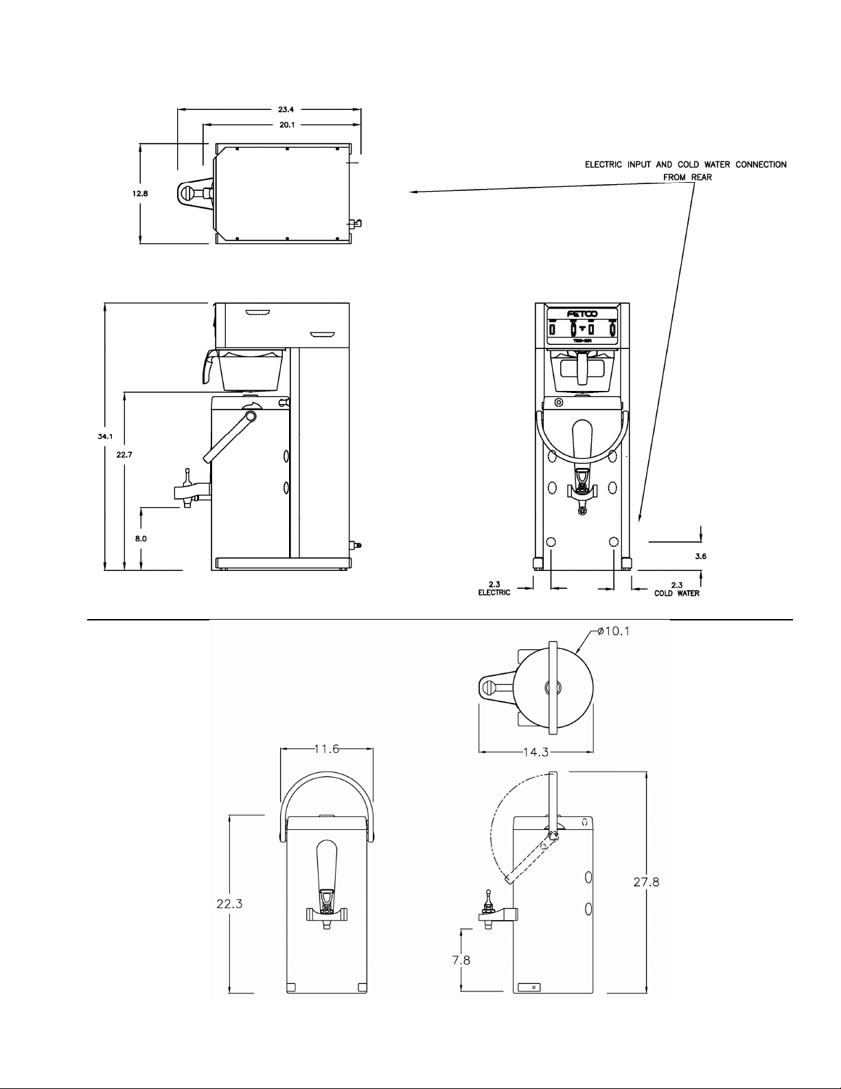
Dimensions & Utility Connections
DWG 201073-005
3
Page 4
Installation
(For Qualified Service Technicians Only)
Keys To A Successful Installation
If not installed correctly by qualified personnel, the brewer may not operate properly and damage may result.
Damages resulting from improper installation are not covered by the warranty.
Here are the key points to consider before installation:
Electrical:
The electrical diagram is located on the inside of the cover.
The installation must comply with applicable federal, state, and local codes having jurisdiction at your
location. Check with your local inspectors to determine what codes will apply.
Plumbing:
This equipment is to be installed to comply with the applicable federal, state, or local plumbing codes.
The water line must be flushed thoroughly prior to connecting it to the brewer to prevent debris from
contaminating the machine. A water filter is strongly recommended.
Never connect the brewer to a hot water supply. Cold water only.
Verify that the water line will provide at least 1.5 gallons per minute
General:
Utilize only qualified beverage equipment service technicians for installation. A Service Company Directory
may be found on our web site, http://www.fetco.com.
Installation Instructions
Brewer Setup
1. Review the Dimensions for the unit you are installing. Verify that the brewer will fit in the space intended
for it, and that the counter or table will support the total weight of the brewer and dispenser when filled.
2. Place the brewer on the counter or stand.
3. When the brewer is in position, level it front to back
and side to side by adjusting the legs.
Water Connection
1. Water inlet is a 3/8 inch male flare fitting.
2. The brewer must be connected to a cold water supply only. Hot water must never be used.
3. Install a water shut off valve near the brewer to facilitate service. If an in-line water filter is used, it should
be installed after the water shut off valve and in a position to facilitate filter replacement.
4. Flush the water supply line and filter before connecting it to the brewer.
5. Verify that the water line will provide at least 1.5 gallons per minute, and that the water pressure is between
20 and 75 psig.
6. Use a wrench on the factory fitting when connecting the incoming water line. This will reduce stress on the
internal connections and reduce the possibility of leaks developing after the install has been completed.
Electrical Connection
1. Verify that the actual voltage at the electrical service connection is compatible with the specifications on the
brewer’s serial number label.
2. The temperature and water tank fill level are pre-set at the factory.
There is no need to turn off the heaters during the installation
process. The heaters are disabled by the control board until the
tank is full of water. The heating process will start automatically
when the tank has filled.
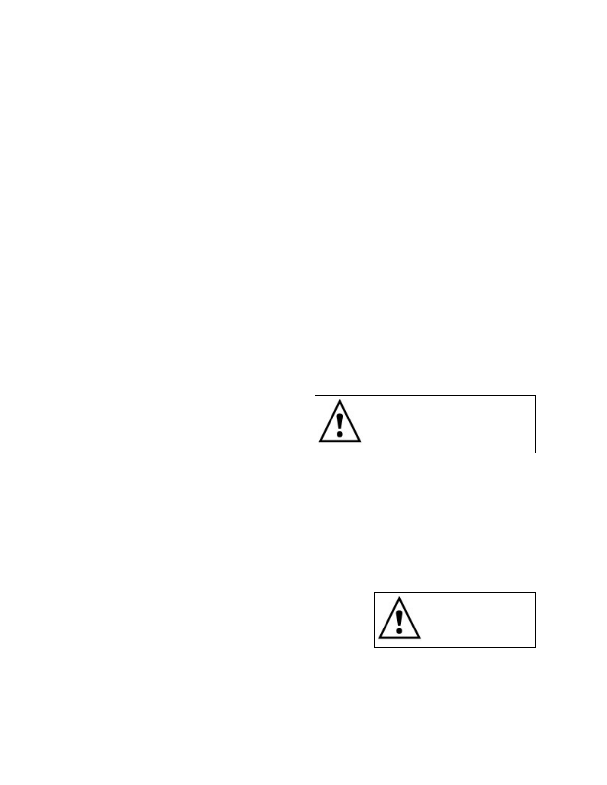
Warning: Legs are to be adjusted for
level ing the brewer only. Do not use
f or height adjustment or extend them
higher than necessary.
W arning: To prevent
electrical shock, this
unit must be properly
groun ded.
4
Page 5

Final Setup
1. Turn on the incoming water supply line and inspect both inside and outside of the brewer for leaks in all
fittings and tubes
2. Turn on the incoming power.
3. Turn on the brewer’s main power switch.
4. Within 6 seconds, the hot water tank will begin filling until the water is sensed by the probe at the top of the
tank.
5. The heaters will be disabled by the control board until the tank is full.
6. The brewer will be ready for operation as soon as the ready light comes on to signify that the water tank is
up to temperature. The time required to reach brewing temperature will vary according to the electrical
configuration ordered.
7. Review the Operating Instructions. Brew one full batch (water only) to confirm proper fill levels. See the
programming instructions to adjust batch settings.
8. Re-attach the covers after one final inspection for leaks. Look closely in the top of the brewer at the
dispense fittings during this inspection.
Operator Training
Review the operating procedures with whoever will be using the brewer. Pay particular attention to the following
areas:
1. Don't remove the brew basket until it has stopped dripping.
2. Make sure the dispenser is empty before brewing into it.
3. Show how to attach covers, close, and or secure the dispensers for transporting.
4. Show the location and operation of the water shut off valve as well as the circuit breaker for the brewer.
5. Steam from the tank will form condensation in the vent tube. This condensation will drip into and then out
of the brew baskets. 1/4 cup discharging overnight is possible. Place an appropriate container under the
brew basket when not in use.
6. We recommend leaving the power to the brewer on overnight. The water tank is well insulated and will use
very little electricity to keep the tank hot. Leaving the brewer in the on position will also avoid delays at the
beginning of shifts for the brewer to reach operating temperature.
5
Page 6

Operating Procedures
1. Turn brewer power switch to the on position
• The power switch will illuminate to indicate that the brewer has power and is operational.
• When the ready light illuminates, the brewer is fully up to temperature. The amount of time required to
gain full operating temperature will vary depending on voltage and the temperature of the incoming
water.
2. Prepare the brew basket.
• Place a paper filter in the brew basket. Pour the appropriate amount of tea or coffee into the paper
filter, and distribute it evenly. The amount used will depend on your personal tastes and the
recommendation of your supplier.
• Slide the brew basket into place. A brew basket sensor will prevent the brewer from operating if the
brew basket is not all the way in. The ready light will blink a few times when the brew switch is
pressed to indicate this error.
3. Place the tea dispenser or coffee dispenser with brewing stand in position under the brew basket.
• Make sure the dispenser is empty. Overflowing may result if it is not completely empty when the brew
cycle begins.
• When brewing tea, ensure that the dilution spout is inserted into the back of the dispenser
• When brewing tea, ensure that the dispenser is pushed all the way in, so that the dispenser body is
pressing the sensing switch. (Iced Tea Only Version: The sensing switch may be disabled for using a
non standard tea dispenser. See # 59 in Diagnostics section.)
• Iced Tea / Coffee Version only: The dispenser sensing switch will prevent coffee from being brewed if
the tea dispenser is in place and vice versa.
4. Start the brew cycle.
• Start a brew cycle by pressing the start switch.
Iced Tea Only Version: The switch has 2 positions, FULL and HALF.
Iced Tea / Coffee Version: The switch has 2 positions: ICED TEA and COFFEE.
• The brew light will be lit during the brew cycle and will blink during the drip delay*, indicating that hot
liquid may still be dripping from the brew basket and that cold water may be flowing into the back of the
tea dispenser through the dilution tube. Do not move the dispenser until the brew light has gone out.
(* Units with red LED display: Brew light blinks during brew cycle and drip delay.)
• CAUTION! Do not remove the brew basket until dripping from the bottom of the brew basket has
stopped. Carefully remove the brew basket while inspecting the inside of the basket for hot liquid that
may have been trapped or has not finished draining.
• To interrupt the brew cycle at any time, press the stop switch. This will reset all functions.
6
Page 7

Programming
f Turn the power switch off.
f Remove the control board cover, located behind the dispenser.
f Turn the power switch on.
f Hold the SET button for 5 seconds, until the display reads SET. SET
f Next, the display will show the software version Example:
f Press SET. The first parameter number will be displayed briefly, 1.0
followed by the current setting.
Example: 1.0 = Batch 1 brew volume, 3.0 gallons
Use the UP and DOWN buttons to adjust the setting.
f Press SET again. The next parameter will be displayed briefly, 1.1
followed by the current setting.
Example: 1.1 = Batch 1 extract percentage, 25%
Use the UP and DOWN buttons to adjust the setting.
f Continue this way until all parameters are programmed.
See the chart below for an explanation of each parameter.
f Important! To save your changes and return to operating mode,
you must hold SET for 5 seconds until the display reads STB. STB
Batch Settings – Iced Tea Only Version
(See next page for Iced Tea / Coffee version)
Parameter Name Range Increment Default Setting Comment
0.0 Software Version
1.0 Batch Volume 1.0 – 3.2 gal. 0.1 3.0 gal.
1.1 Extract % 1% - 50% 1% 25% Not to exceed 1 gal.
1.2 Pulses 1 – 25 1 1
Batch 1 - Full
Batch 2 - Half
1.3 Brew Time
(If 1.2 > 1)
1.4 Dilution During
Brew
(If 1.2 > 1)
1.5 Dilution Delay
(If 1.4 = 0)
1.6 Drip Delay 0:10 – 15:00 min. 10 sec. 3:00 min.
2.0 Brew Volume 1.0 – 3.2 gal. 0.1 1.5 gal.
2.1 Extract % 1% - 50% 1% 25% Not to exceed 1 gal.
2.2 Pulses 1 – 25 1 1
2.3 Brew Time
(If 2.2 > 1)
2.4 Dilution During
Brew
(If 2.2 > 1)
2.5 Dilution Delay
(If 2.4 = 0)
2.6 Drip Delay 0:10 – 15:00 min. 10 sec. 1:30 min.
2:00 – 15:00
10 sec. 4:00 min.
minutes
0 - 1 0 0 = no
0 – 15:00 min. 0:10 3:00 min.
2:00 – 15:00
10 sec. 4:00 min.
minutes
0 - 1 0 0 = no
0 – 15:00 min. 0:10 1:30 min.
CONTROL BOARD
Display
0.30
3.0
The display shows the
actual water temperature
when not in Programming
25
1 = yes
1 = yes
mode.
7
Page 8

Batch Settings – Iced Tea / Coffee Version
(See previous page for Iced Tea Only version)
Parameter Name Range Increment Default Setting Comment
0.0 Software Version
1.0 Batch Volume 1.0 – 3.2 gal. 0.1 3.0 gal.
1.1 Extract % 1% - 50% 1% 25% Not to exceed 1 gal.
1.2 Pulses 1 – 25 1 1
Batch 1
Iced Tea
1.3 Brew Time
(If 1.2 > 1)
1.4 Dilution During
Brew
(If 1.2 > 1)
1.5 Dilution Delay
2:00 – 15:00
10 sec. 4:00 min.
minutes
0 - 1 0 0 = no
1 = yes
0 – 15:00 min. 0:10 3:00 min.
(If 1.4 = 0)
1.6 Drip Delay 0:10 – 15:00 min. 10 sec. 3:00 min.
2.0 Brew Volume 0.1 – 1.0 gal. 0.1 0.8 gal.
2.2 Pulses 1 – 25 1 8
Batch 2
2.3 Brew Time
Coffee
(If 2.2 > 1)
2.6 Drip Delay 0:10 – 15:00 min. 10 sec. 1:00 min.
2:00 – 15:00
minutes
10 sec. 4:00 min.
Temperature Settings
Parameter Name Range Increment Default Setting Comment
3.0 Water Temp. (°F) 180°F - 211°F 1°F 205°F
4.0 Brew Only at Set
Temperature
0 - 1 1 0=Will brew only at set
temperature.
1=Will brew at any
temperature.
5.0 Enter Diagnostics 0 - 1 0 0 = no
1 = yes
Press SET to continue.
Diagnostics
Address Description Range Default Comment
50 Water Level
in Tank
51 Tank Temperature
52 Brew Switch, top
(Full batch or iced tea)
53 Brew Switch, bottom
(Half batch or coffee)
54 Brew Basket Sensor 0 - 1 To test, slide the brew basket in and out. Display
55 Dispenser Sensor 0 - 1 Press switch to test. Display should toggle
56 Display Recent Errors Scroll to display the 5 most recent errors.
57 Master Clear Errors 0 - 1 0 Clears errors stored in memory. (See #56)
58 Reset Defaults 0 - 1 0 Changes all settings to default factory settings.
59 Dispenser Sensor
(Choice not available on
Iced Tea / Coffee version)
60 Enter Relay Test 0 - 1 0 0 = no
Press SET to continue.
0 - 1 Tests if water is touching probe.
0 = Tank is less than full
1 = Tank is full
32°F -
Displays current tank temperature.
212°F
0 - 1 Press switch to test. Display should toggle
between 0 and 1.
0 - 1 Press switch to test. Display should toggle
between 0 and 1.
should toggle between 0 and 1.
0 = Brew basket out. 1 = Brew Basket in.
between 0 and 1.
Clears error code 050 and 051.
0 = Do not reload defaults
1 = Reload all default settings
0 - 1 1 0=Will brew with or without dispenser in place.
1=Will brew only if dispenser is in place.
1 = yes
8
Page 9

Relay Test
Tests the individual relays which control various components.
Use the UP or Down button to actuate the relays.
Warning: During these
tests, hot w ater m ay
be dispens ed fr om
t he va lve being tes ted.
90 Fill Valve
91 Dilution Valve
92 Brew Valve
93 Ready Light
94 Brew Light
95 Heater Triac To protect the heaters, this test will work only if the tank is full.
Error Codes
001 Software - System Reloaded Defaults
003 Internal CPU or Board Error
050* Shorted Temperature Probe
051* Open Temperature Probe
060 Flow Error
075 Brew Basket Sensor Open
076 Container Sensor Open
To reset error codes, turn the power switch off and on.
Error 050 and 051 must be reset through the Master Clear function – see address #57 in Diagnostics.
100 Initial Fill Error (> 10 minutes)
101 Error On Refill (> 2 minutes)
102 Unwanted Fill
200 Flat Line Temperature / Shorted Heater
201 Open Heater
255 Stuck Switch
9
Page 10

Wiring Diagram
10
Page 11

Cleaning & Maintenance
Brewer
Daily: Wipe the area above the brew basket to remove coffee and tea residue.
Daily or Weekly: The spray plate should be removed and cleaned to remove hard water deposits. In areas
with extremely hard water, it may be necessary to do this daily. Weekly cleaning may be sufficient in some
areas.
When cleaning the spray plate, make sure that each hole is completely free of mineral deposits. A
toothpick may be used for cleaning out the holes. Never use metal objects or abrasives on the spray
plate’s Teflon coating.
Tea Dispenser
f The dispenser liner should be cleaned and sanitized daily using a commercial tea dispenser
cleaner/sanitizer.
f Do not scratch the plastic liner by using abrasive products or tools.
f Never leave tea in the dispenser overnight.
1. Add the recommended amount of sanitizer for 3 gallons to the empty dispenser.
2. Brew a complete batch with water only into the dispenser and let the solution sit for the recommended
amount of time
3. Empty the dispenser through the faucet.
4. Lift the liner out of the dispenser and remove the faucet as shown below. Do not remove the spring from
the faucet shank.
5. Disassemble the faucet by unscrewing the nut below the handle.
6. Use the enclosed brush to clean out the faucet shank and the exposed surfaces of the faucet parts.
7. Thoroughly rinse the liner, faucet parts, and dispenser cover with warm water.
8. Re-assemble the faucet, attach it to the liner, and place it into the dispenser body.
9. Wipe the stainless steel body with a damp cloth.
To remove the faucet:
Push in against spring
Rotate 180°
Pull out
To attach the faucet, hold it upside-down,
push it on to the faucet shank, and rotate
it to the upright position. The spring will
lock the faucet in place.
11
Page 12

ITD-30 Dispenser
Product Number D031
Dispenser Parts
(Revised Nov. 2003)
ITEM QTY PART NO. DESCRIPTION
1 1 23088 COVER, ITD-30
2 1 23089 HANDLE
3 1 23087 LINER, ITD-30
4 1 85025 SPRING, COMPRESSION
5 1 102204 FAUCET, COMPLETE
6 2 23090 PLUG
7 1 71088 FAUCET UPPER ASSY., BLACK HANDLE
8a 1 71028 FAUCET HANDLE, BLACK
8b 1 71035 FAUCET SEAT CUP
9 1 102199 FAUCET HOUSING ASSY.
10 2 84029 HEX NUT, 5/16-18 S.S.
11 2 13036 HANDLE PIVOT
13 2 23091 DISPENSER-GUIDE
14 2 82079 SCREW, #10 X 1/2'' PHIL. TRUSS HD. TAPPING
12
Page 13

Airpot & Stand (Iced Tea / Coffee Version)
Product Number D041
3.0 Liter Stainless Steel Lined Lever Airpot
Product Number A095
Airpot Brewing Stand
Replacement Parts
PART # DESCRIPTION
71082 LID, LEVER TYPE
99024 TUBE ASSY.
13
Page 14

Figure 1
Brewer Parts
14
Page 15

Parts List – Figure 1
ITEM QTY PART NO. DESCRIPTION
3 1 46011 BREW BASKET WARNING DECAL
4 1 101178 BREW BASKET ASSY., 0.206” DIA. HOLE (STANDARD - ICED TEA) (SEE FIGURE 4)
4 1 101165 BREW BASKET ASSY., 0.280” DIA. HOLE (STANDARD - COFFEE) (SEE FIGURE 4)
4 1 101179 BREW BASKET ASSY., 0.161” DIA. HOLE (OPTIONAL - ICED TEA) (SEE FIGURE 4)
4 1 101180 BREW BASKET ASSY., 0.110” DIA. HOLE (OPTIONAL - ICED TEA) (SEE FIGURE 4)
5 1 01511 TBS-21A TOP COVER
6 1 102080 SPRAY HOUSING ASSY. (SEE FIGURE 3)
7 1 45070 OVERLAY, TBS-21A Iced Tea only version
7 1 45071 OVERLAY, TBS-21A Iced Tea / Coffee version
9 1 58064 READY LAMP 120VAC
10 1 58072 START SWITCH, 240V
11 1 58067 BREW LAMP, 120V
12 13 84022 #8-32 S.S. HEX NUT
16 1 58062 STOP SWITCH 240V
17 1 58063 SWITCH, POWER, 240VAC, 110V LAMP
18 1 13070 TBS-21A DILUTION FITTING
19 1 58016 SWITCH, DISPENSER SENSING
20 1 46030 TBS-21A CONTROL PANEL LABEL
21 1 01533 TBS-21A CONTROL COVER
22 4 23075 TBS-21A LEG SUPPORT END CAP
23 4 83019 5/16 FLAT WASHER
24 4 84015 5/16-18 HEX NUT
25 4 21066 TBS-21A LEG
27 4 82004 #6-32 x .625" SCREW
28 1 25036 .5 I.D. X .75 O.D. X 5.75'' L SILICONE TUB
29 1 86020 NYLON HOSE CLAMP .750 MIN .875 MAX DIA
30 1 102013 TANK COVER ASSEMBLY
31 1 24002 TANK COVER GASKET
32 4 86007 NYLON HOSE CLAMP MIN.593, MAX .656
34 1 86032 HEYCO 1 INCH HOLE SNAP BUSHING
35 1 104022 TBS-21A TANK ASSEMBLY (SEE FIGURE 2)
36 1 31128 3/8 FLARE 1/4 MPT , HOSE BARB ELBOW
37 1 33007 7/16 DISPENSE TUBE LOCKNUT
38 1 03289 TBS-21A DILUTION TUBE WASHER
40 2 25066 COLD WATER AND DILUTION SILICONE TUBE .375 I.D. X .610 O.D. X 17 L.
41 1 86012 .875 X .840 STRAIN RELIEF BUSHING
42 1 63019 TBS-21A POWER CORD 20AMPS, 120VAC
43 4 15006 TBS-21A CONTROL PANEL STANDOFF
44 1 K020
44 1 K021
45 1 01513 TBS-21A BACK COVER
46 1 401169 TBS-21A WIRING DIAGRAM
48 2 57006 FILL VALVE, S-53N, 1.35 GPM, 120VAC
49 1 03300 TBS-21A VALVES/FLOWMETER BRACKET
50 1 57081 FLOWMETER (DIGMESA)FF JG 50 3/8'' WITH MTG SCREWS
51 1 25068 TWO WAY DIVIDER 3/8''TUBE O.D.
52 1 25073 TBS-21A L1 TUBE
CONTROL BOARD REPLACEMENT KIT, ICED TEA ONLY, STANDARD SOFTWARE
(INCLUDES CONTROL BOARD AND #102172 DIGITAL TEMP PROBE ASSY)
CONTROL BOARD REPLACEMENT KIT, ICED TEA/COFFEE, STANDARD SOFTWARE
(INCLUDES CONTROL BOARD AND #102172 DIGITAL TEMP PROBE ASSY)
15
Page 16

55 2 25074 TBS-21A L2 TUBE
56 1 52050 CURTIS BT-3 TERMINAL BLOCK
57 1 59008 TRIAC 40A 600V
58 1 03297 TRIAC HEAT SINK (SEE NOTES)
61 1 53064 SINGLE SHOT TERMOSTAT (TRIAC VERSION)
62 1 21063 DILUTION SWITCH STAND-OFF
63 4 84001 #6 NUT
64 2 25067 3/8" TUBE MALE CONNECT.
69 3 82006 #10-32 3-8 PHILIPS SCREW
71 1 101158 BREW BASKET SENSOR ASSY
72 1 86030 TANK DRAIN CLAMP
73 1 86038 HEYCO CLAMP
74 1 25072 TBS-21A VENT TUBE .5'' X .25'' X 8.5''
75 1 25075 TBS-21A L3 TUBE
76 1 03233 LIMITING THERMOSTAT BRACKET
77 1 402005 HARNESS
80 1 83035 #8 LOCK WASHER
82 6 32026 # 8 INTERNAL TOOTH WASHER
83 1 44004 "GROUND" LABEL
84 4 83039 # 6 INTERNAL TOOTH WASHER
85 16 82053 # 6 - 32 x 1/2
86 6 86043 3/8" LOCKING CLIP
87 1 31151 1/2 MPT LOCK NUT
88 1 31164 3/8 X 1/2 FPT FEMALE 90 DEG. ELBOW
89 1 31165 3/8 FPT X 1/2 MPT BUSHING
90 3 25067 3/8" TUBE MALE CONNECT.
93 1 59009
93 1 59010
94 2 84030 #8-32 HEX NYLON-INSERT LOCKNUT
95 2 83040 #8 S.S. FLAT WASHER
SOFTWARE CHIP FOR TBS-21A ICED TEA ONLY VERSION
(USE ONLY WITH OLD STYLE CONTROL BOARDS WITH RED LED DISPLAY)
SOFTWARE CHIP FOR TBS-21A ICED TEA / COFFEE VERSION
(USE ONLY WITH OLD STYLE CONTROL BOARDS WITH RED LED DISPLAY)
16
Page 17

Figure 2 – Tank Assembly
ITEM QTY PART NO. DESCRIPTION
1 1 K025 WATER LEVEL PROBE REPLACEMENT KIT
2 ---------- INCLUDED WITH K025
3 2 31117 1/4" LOCKNUT
4 1 31116 1/8" LOCKNUT
5 1 83043 .688 I.D. X 1.1250 O.D. FLAT WASHER
7 1 31071 1/2" HOSE BARB X 3/8" MPT
8 1 31128 3/8" HOSE BARB X 1/4" MPT 90 DEG. ELBOW
9 1 107014 2100W 120V HEATING ELEMENT
10 1 83041 .412 X .812 FLAT WASHER
11 1 31005 1/4"HOSE BARB X 1/8"MPT 90 DEG.ELBOW
12 1 54022
12 1 102172
13 1 31036 1/4" COMP. X 1/4"MPT CONNECTOR
16 1 31118 3/8" LOCKNUT
17 1 004026 TANK WELDMENT
18 1 31021 .75'' -16 X .25'' FSPT HEX HEAD BUSHING
19 1 84007 .75'' x 16 S.S. NUT
8.0", 50K OHM TEMPERATURE PROBE
(USE ONLY WITH OLD STYLE CONTROL BOARDS WITH RED LED DISPLAY)
8.0” DIGITAL TEMPERATURE PROBE ASSY.
(USE ONLY WITH NEW STYLE CONTROL BOARD WITH GREEN LED
DISPLAY. INCLUDED WITH #K020 CONTROL BOARD REPLACEMENT KIT.)
DWG 102044-001
17
Page 18

Figure 3 – Spray Housing Assembly
2
1
4
3
5
6
ITEM # QTY PART NO DESCRIPTION
1 4 82112 #8 X 3/4'' PAN HD. PHIL. T.S. 18-8 S.S. SCREW
2 1 57047 COIL ASSY. REPAIR KIT, DSV-11, 120 VAC
2 1 57071 COIL ASSY. REPAIR KIT, DSV-11, 240 VAC (EXPORT VERSION ONLY)
3 1 57073 VALVE REBUILD KIT, DSV11
4 1 102082 SPRAY HOUSING ASSY.
5 1 24054 O-RING 4.237” I.D.
6 1 102081 SPRAY PLATE ASSY., 4 7/8" DIA.
18
Page 19

Figure 4 – Brew Basket Assembly, 16” X 6”
FOR ICED TEA: PART # 101178 - BREW BASKET ASSY. WITH 0.206” DIA. HOLE (STANDARD)
PART # 101179 - BREW BASKET ASSY. WITH 0.161” DIA. HOLE (OPTIONAL)
PART # 101180 - BREW BASKET ASSY. WITH 0.110” DIA. HOLE (OPTIONAL)
FOR COFFEE: PART # 101165 - BREW BASKET ASSY. WITH 0.280”. DIA HOLE
1
ITEM QTY PART # DESCRIPTION
1 1 82096 HANDLE SCREW
2 1 23117 BREW BASKET HANDLE, BLACK
2
3 1 9006 WIRE INSERT, 16 X 6
NOT
SHOWN
3
F001 PAPER FILTERS, 15” X 5.5”
500 PER CASE
COLOR BREW BASKET HANDLES
PART # DESCRIPTION
23106 BREW BASKET HANDLE, GREEN
23107 BREW BASKET HANDLE, ORANGE
23148 BREW BASKET HANDLE, RED
19
Page 20

 Loading...