

Page 1
www.fetco.com
www.fetco.com
www.fetco.comwww.fetco.com
Hot Water Dispensers
Hot Water Dispensers
Hot Water DispensersHot Water Dispensers
Table of Contents
Contact Information ................................................... 2
Specifications............................................................. 2
Dimensions ................................................................ 3
Installation.................................................................. 4
User’s Guide
User’s Guide
User’s GuideUser’s Guide
Maritime Versions
Maritime Versions
Maritime VersionsMaritime Versions
Rated IP44
Rated IP44
Rated IP44 Rated IP44
Operating Instructions.................................................6
Programming ..............................................................7
Wiring Diagrams .........................................................8
Parts .........................................................................10
FETCO®, and Driven To Pioneer Innovation™ are trademarks or trade names of Food Equipment Technologies Company.
© 2009 Food Equipment Technologies Company Part # P113 REV. 001
Page 2

Contact Information
Contact Information
FETCO®
Food Equipment Technologies Company
600 Rose Road
Lake Zurich • IL • 60047-0429 • USA
Internet: www.fetco.com
Contact InformationContact Information
Service & Support:
Hours: 7:00 AM - 6:00 PM Central, Monday - Friday
Phone: (800) 338-2699 (US & Canada)
(847) 719-3000
Fax: (847) 719-3001
Email: techsupport@fetco.com
Specifications
Specifications
SpecificationsSpecifications
Maritime Versions with IP44 Ingress Protection Rating
Water Requirements
Pressure: 20-75 psig
Minimum Flow Rate: 1.5 gpm
Water Temperature
Factory Setting: 96°C / 205°F
Range: 82° - 98°C / 180° - 208°F
Weights & Capacities
Model Weight (empty) Water tank Capacity. Weight (full)
HWB-5 44 lbs. 5 Gallons 85 lbs.
HWB-10 66 lbs. 10 Gallons 149 lbs.
Electrical Configuration and Heating Efficiency
HWB-5
Electrical Heater Voltage Maximum Hourly Heating Capacity* (gallons)
Config. Code Configuration (AC) Phase Wires KW Amp Draw Cold Water Hot Water
H05041MIP 1 X 3.0 KW 220 1 ph. 2 + ground 2.5 11.6 6.2 14.4
240 1 ph. 2 + ground 3.0 12.6 7.4 17.2
HWB-10
Electrical Heater Voltage Maximum Hourly Heating Capacity* (gallons)
Config. Code Configuration (AC) Phase Wires KW Amp Draw Cold Water Hot Water
H10031MIP 2 X 3.0 KW 220 3 ph. 3 + ground 5.0 11.6 12.5 28.8
240 3 ph. 3 + ground 6.0 12.6 14.9 34.3
*Heating capacity is based on factory setting - 96°C / 205°F
2
Page 3
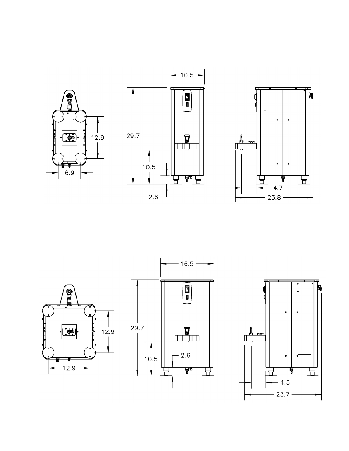
HWB-5
Dimensions
Dimensions
DimensionsDimensions
HWB-10
3
Page 4

necessary.
Installation
Installation
InstallationInstallation
(For Qualified Service Technicians Only)
Keys To A Successful Installation
Electrical:
• The power switch has a built-in circuit breaker. To reset it, turn to the “OFF” position, and then back to the
“ON” position.
• The wiring diagram for the dispenser is located on the inside of the cover.
Plumbing:
• The water line must be flushed thoroughly prior to connecting it to the dispenser to prevent debris from
contaminating the machine. An in-line water filter is strongly recommended.
• Verify that the water line will provide at least 1.5 gallons per minute before connecting it to the dispenser.
• The end of the vent tube must be open to the air, not connected to anything or submerged in liquid.
General:
• The installation must comply with applicable federal, state, and local codes having jurisdiction at your
location.
• Utilize only qualified beverage equipment service technicians for installation. A Service Company Directory
may be found on our web site, http://www.fetco.com.
• Do not adjust the thermostat settings unless absolutely necessary. They are set at the factory for optimum
performance.
Installation Instrucions
Setup
1. Before placing the unit, verify that it will fit in the space intended for it, and
that the counter or table will support its’ weight.
2. Place the unit on its back and screw in the legs.
3. Place the unit on the counter or stand.
4. When the unit is in position, level it front to back as well as side-to-side by
adjusting the legs.
5. Mark the surface of the counter with the location of the mounting holes in the legs.
6. Drill ¼” diameter holes in the counter and secure the legs to the counter with bolts and nuts (not included).
Water Connection
1. The water inlet is a 3/8” male flare fitting.
2. The dispenser can be connected to cold or hot water. Cold water is preferred for best flavor, but hot water will
allow for faster recovery times. Use of an in-line water filter is strongly recommended.
3. Install a shut off valve near the unit to facilitate service. If an in-line water filter is used, it should be installed
after the water shut off valve and in a position to facilitate filter replacement.
4. Flush the water supply line and filter before connecting it to the unit.
5. Verify that the water line provides at least 1.5 GPM, and that the water pressure is between 20 and 75 psig.
Vent Tube Connection
1. Condensation and steam from the water tank is discharged from the 3/8-inch hose barb fitting on the back of
the unit.
2. Attach a hose (not provided) to the fitting and run it to a drain, sink or a container. The end of the vent tube must
be open to the air, not connected to anything or submerged in liquid.
Electrical Connection
1. Verify that the actual voltage at the electrical service connection is compatible with the specifications on the
unit’s serial number label.
2. The temperature and water tank fill level are pre-set at the factory. There is no need to turn off the heaters
during the installation process. The control board disables the heaters until the tank is full of water. The
heating process will start automatically when the tank has filled.
4
Warning: Legs are to be
adjusted only for
leveling the unit.
Do not extend them
higher than
Page 5
L1
L1L1
L1
GROUND LUG
GROUND LUGGROUND LUG
GROUND LUG
GROUND
GROUNDGROUND
GROUND
WIRE
WIREWIRE
WIRE
GROUND
GROUNDGROUND
GROUND
WIRE
WIREWIRE
WIRE
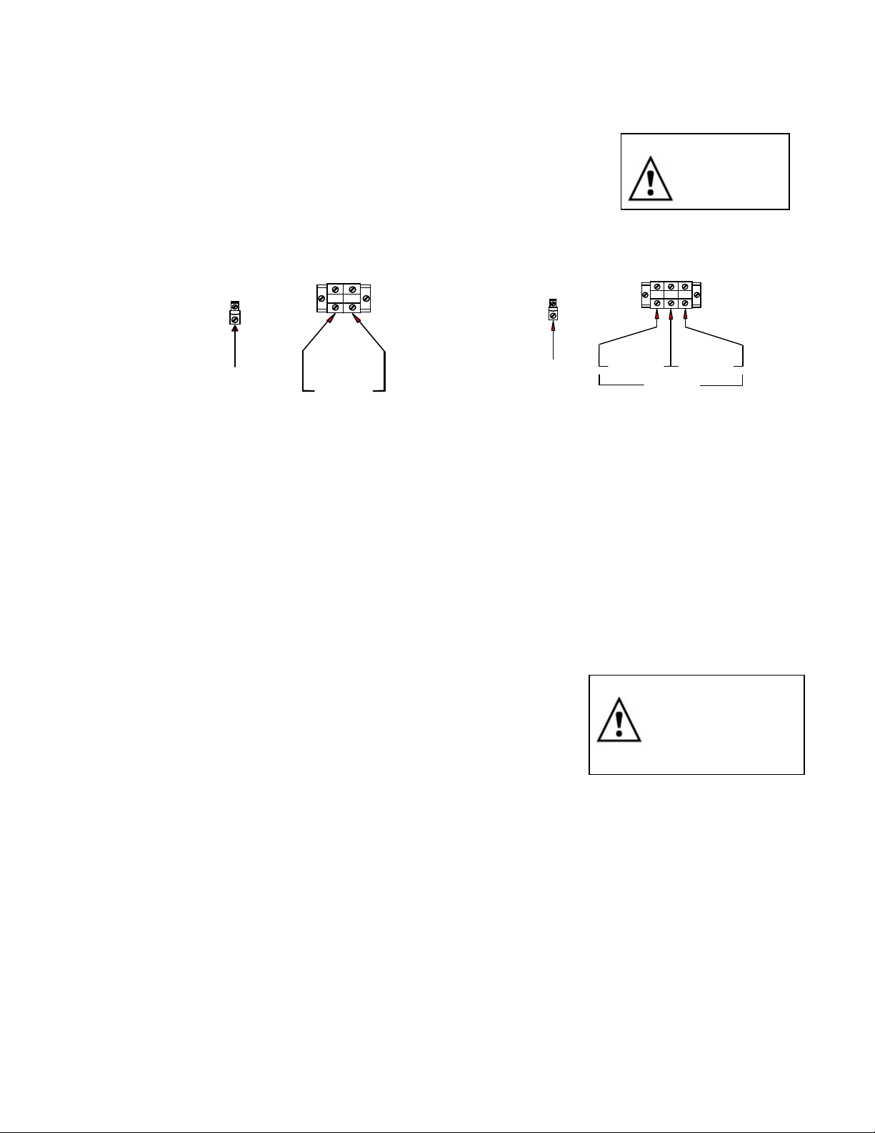
3. A terminal block is provided for connecting the incoming power wires. Consult local codes to determine if a cord
and plug can be installed, or if the unit must be hard wired.
4. A fused disconnect switch or circuit breaker on the incoming power line must be conveniently located near the
unit, and its location and markings known to the operators.
5. The body of the unit must be grounded to a suitable building ground. A ground
lug is provided next to the power terminal block. Use only 10 gauge copper
wire for grounding.
6. Electrical connections must be secured in-place within the unit to meet
Warning: To prevent
electrical shock,
this unit must be
properly grounded.
national and local standards.
7. Connect the incoming power wires to the terminal block in accordance with
applicable codes.
HWB
HWB----10 TERMINAL BLOCK
10 TERMINAL BLOCK
HWBHWB
HWB
HWB----5 TERMINAL BLOCK
5 TERMINAL BLOCK
HWBHWB
5 TERMINAL BLOCK5 TERMINAL BLOCK
L2
L2
L2L2
10 TERMINAL BLOCK10 TERMINAL BLOCK
GROUND LUG
GROUND LUG
GROUND LUGGROUND LUG
L1
L1 L2
L1L 1
L2 L3
L2L 2
L3
L3L 3
220
220----240V
240V 220-240V
220220
240V240V
220
220----240V
240V
220220
220
220----240V
240V
220220
240V240V
240V240V
Final Setup
1. Turn on the incoming water supply line and inspect both inside and outside of the unit for leaks in all fittings and
tubes.
2. Turn on the incoming power line and the power switch
3. Within 6 seconds, the water tank will begin filling until the probe at the top of the tank senses the water. The fill
valve will pulse off and on while the tank is filling. The heaters will be disabled until the water probe at the top of
the tank senses water.
4. Review the programming instructions and make any necessary adjustments.
5. Re-attach the cover after one final inspection for leaks.
Operator Training
Review the operating procedures with everyone who will be using the unit. Pay particular attention to the following
areas:
1. Demonstrate the hot water faucet.
2. Demonstrate the shut off valve behind the faucet, and review the safety
warning at right.
3. Show the location and operation of the water shut off valve and the circuit
breaker for the unit.
Warning: Do not disassemble the
faucet without first closing
the shut-off valve behind
the faucet.
Extremely hot water.
May cause serious burns.
5
Page 6

Operating Instructions
Operating Instructions
Turn the power switch to the ON position. The power switch will illuminate to indicate that the dispenser has power
and is operating.
When the ready light illuminates, the dispenser is fully up to temperature and ready to dispense hot water through
the faucet. The amount of time required to gain full operating temperature will vary depending on the electrical
configuration, and the temperature of the incoming water.
Safety Precautions:
• Do not hang containers or any other object from the faucet or faucet guard.
• Do not disassemble the faucet without closing the shut-off valve located behind the faucet.
Operating InstructionsOperating Instructions
Operating Principles
When hot water is drawn from the faucet, the fill valve pulses on and off every few seconds to slowly refill the tank.
(See %FV setting in the Programming section.)
By controlling the flow of incoming water, the amount of cold water entering the tank is synchronized with the rate at
which the water can be heated. This ensures an uninterrupted supply of hot water. When dispensing water at a rate
that exceeds the unit’s capacity to heat, the flow of water out of the faucet will be diminished to maintain the proper
temperature.
Maintenance
Quarterly:
• Inspect all fittings and hoses for leaks.
• Inspect inside of tank for lime deposits. De-lime tank and probes if necessary. This procedure should be
done by a qualified service technician.
6
Page 7

8 5 0 5
Programming
Programming
ProgrammingProgramming
The display shows the current water tank temperature in ° Celsius when
in normal operating mode.
Temperature may be set in either Celsius or Fahrenheit.
Service note: Whenever the digital temperature probe is replaced, it will be
necessary to reprogram all settings on the control board.
Remove the top cover of the unit.
The control board is located on the left side near the front.
Turn the power switch ON.
Press and hold the SET button for 3 seconds.
Temperature setting in °C will be displayed and °C indicator lamp will be lit.
To adjust, press and release SET quickly to advance one degree at a time.
Range: 82-98 °C
Press and hold SET for 3 seconds.
Temperature setting in °F will be displayed and °F indicator lamp will be lit.
To adjust, press and release SET quickly to advance one degree at a time.
Range 180-208 °F
Only the last 2 digits of the temperature will be displayed.
Example: 185°F is displayed as 205°F is displayed as
Press and hold SET for 3 seconds. The fill valve % will be displayed and the %FV
indicator lamp will be lit.
To adjust, press and release SET quickly to advance one percent at a time.
Refer to the chart below for the proper setting for your model and voltage.
Range: 15% – 100%.
The unit will automatically return to normal operating mode after 30 seconds
without programming activity.
Select the model and actual voltage to determine the correct %FV setting
for step 5.
Heater Actual %FV
Model Configuration Voltage Phase Setting
HWB-5 1 X 3000 watt 220 1 ph.
240 1 ph.
HWB-10 2 X 3000 watt 220 3 ph.
240 3 ph.
15
17
28
33
TEMPERATURE
CONVERSION
°°°°C °°°°F
82 180
83 181
83 182
84 183
84 184
85 185
85 186
86 187
87 188
87 189
88 190
88 191
89 192
89 193
90 194
90 195
91 196
92 197
92 198
93 199
93 200
94 201
94 202
95 203
95 204
96
97 206
97 207
98 208
factory setting
96°°°°C / 205°°°°F
205
7
Page 8

HWB-5
Wiring Diagrams
Wiring Diagrams
Wiring DiagramsWiring Diagrams
8
Page 9

HWB-10
9
Page 10

Figure 1 – HWB-5 – Main Assembly
Parts
Parts
PartsParts
10
Page 11

ITEM # QTY PART # DESCRIPTION
1
N/A N/A
2 2 03496 COVER, DRAIN OPENING, HW B'S, 304SS
3 1 104042 ASSEMBLY, TANK HWB-2005 (SEE FIG. 2)
4 1 13083 SHANK REAR HWB-2000'S
5 1 84007 NUT, 3/4-16 HEX JAM
6 1 34007 VALVE, BALL, 1/2" HWB-2000
7 1 13082 SHANK FRONT HWB-2000'S
8 1 71036 C - RING
9 1 31045 NUT, UNION 1-1/8 HEX
10 1 71078 FAUCET, HWB-2000
10 1 71035 FAUCET SEAT CUP, ES
10 1 71079 FAUCET UPPER ASSEMLBY, RED HANDLE, HWB
11 1 24012 GASKET, S-53 FILL VALVE
12 1 31078 FITTING, S-53 FILL VALVE INLET
13 1 03074 BRACKET, S-53
14 4 82020 SCREW, S-53 FILL VALVE
15
N/A N/A
16 1 31117 LOCKNUT 1/4"-18 NPT
17 1 25107 TUBE, 5/8"OD X 3/8"ID X 4.5"LG,COLD WATER, HWB-2005
18 2 86007 CLAMP, HOSE, .593"-.656" DIA RANGE
19 1 25108 TUBE, 1/2"OD X 1/4"ID X 7.0"LG VENT. HWB-2005
20 1 102213 ASSEMBLY, DIGITAL TEMP. PROBE, 12.0"LG/34"LG WIRE
21 1 102222 ASSEMBLY, WATER LEVEL PROBE, HWB-2000
22 1 45085 OVERLAY, HWB-2005
23 1 58006 LAMP, BREW 120VAC
24 1 52076 BREAKER,CIRCUIT 120VAC ROCKER SWITCH 6 AMP
25 8 83076 WASHER,#8 SCREW SIZE, CUSHION AND SEALING
26 2 29020 SPACER, HOT WATER VALVE
27 1 102221 ASSEMBLY, HEAT SINK HWB-2005
28 1 108013 ASSY. BOARD, CONT.& SOFT, HWB-2000, 230VAC
29 4 15007 STANDOFF, MALE-FEMALE, THREADED HEX 4-40-1/2"
30 1 65002 CONNECTOR, COPPER LUG
31 1 22077 INSULATION, TANK FRONT, HWB-2005
32 1 22078 INSULATION, TANK BACK, HWB-2005
33 2 22079 INSULATION, TANK, SIDE, HWB-2005/2010
34 1 22092 INSULATION, TANK TOP, HWB-2005
35 1 44004 LABEL GROUND
36 1 402141 HARNESS, LOW AMP, HWB-2005
37 1 22076 INSULATION, TANK BOTTOM, HWB-2005
38 1 402142 HARNESS, HIGH AMP, HWB-5, IP44, HALOGEN FREE
39 1 102223 ASSEMBLY, WATER LEVEL PROBE, HWB-2000, CBS-70'S
40 1 401370 W IR.DIAG., HW B-5, L1, L2+GRND,240VAC, 1 HTR
41 1 58086 BOOT, PROTECTIVE, NEON LAMP, IP44
42 1 52093 BOOT, PROTECTIVE, POWER SWITCH, IP44
43
N/A N/A
44 4 73021 LEG, INSERT, ADJ. FOOT S/S FLANGED W/ HOLES
45 1 002461 W ELDMENT, COVER, HWB-5, 304 S.S.
46 1 402145 GROUND WIRE, HALOGEN FREE
47 1 52050 TERMINAL BLOCK
48
N/A N/A
49 1 57059 FILL VALVE, S53, .75GPM, 240V EXPORT
NOT AVAILABLE FOR SALE
NOT AVAILABLE FOR SALE
NOT AVAILABLE FOR SALE
NOT AVAILABLE FOR SALE
11
Page 12

Figure 2 – HWB-5 – Tank Assembly, Part # 104042
ITEM # QTY PART # DESCRIPTION
1 1 004027 WELDMENT, TANK HWB-2005
2 1 53071 THERMOSTAT, SINGLE SHOT, 25A
3
4
N/A N/A
N/A N/A
5 5 31117 LOCKNUT 1/4"-18 NPT
6 1 107004 ASSEMBLY, HEATER, IMMERSION, 3000W/240VAC
7 1 24002 O-RING, TANK COVER
8 1 102013 ASSEMBLY, TANK COVER
9 1 102224 ASSEMBLY, TANK DRAIN, HWB-2000
10 1 32067 TUBE, 3/8"OD X 13.0LG COLD WATER INLET HWB-2000
NOT AVAILABLE FOR SALE
NOT AVAILABLE FOR SALE
12
Page 13

Figure 3 – HWB-10 – Main Assembly
13
Page 14

ITEM # QTY PART # DESCRIPTION
1
2 1 104044 ASSEMBLY, TANK HWB-2010 (SEE FIG. 4)
3 1 22107 INSULATION, TANK BOTTOM, HWB-2010
4 1 102223 ASSEMBLY, WATER LEVEL PROBE, HWB-2000, CBS-70'S
5 1 102213 ASSEMBLY, DIGITAL TEMP. PROBE, 12.0"LG/34"LG WIRE
6 1 102222 ASSEMBLY, WATER LEVEL PROBE, HWB-2000
7
8 2 03496 COVER, DRAIN OPENING, HW B'S, 304SS
9 8 83076 WASHER,#8 SCREW SIZE, CUSHION AND SEALING
11 1 84007 NUT,3/4-16 HEX JAM
12 1 13083 SHANK REAR HWB-2000'S
13 1 34007 VALVE, BALL, 1/2" HWB-2000
14 1 13082 SHANK FRONT HWB-2000'S
15 1 71036 C - RING
16 1 31045 NUT, UNION 1-1/8 HEX
17 1 71078 FAUCET, HWB-2000
17 1 71035 FAUCET SEAT CUP, ES
17 1 71079 FAUCET UPPER ASSEMBLY, RED HANDLE, HWB
18 4 29020 SPACER, HOT WATER VALVE
19 2 102221 ASSEMBLY, HEAT SINK HWB-2005
22 1 108013 ASSY. BOARD, CONT.& SOFT, HWB-2000, 230VAC
24 4 15007 STANDOFF, MALE-FEMALE, THREADED HEX 4-40-1/2"
25 1 52050 TERMINAL BLOCK
26 1 65002 CONNECTOR, COPPER LUG
27 1 44004 LABEL GROUND
28 1 57059 FILL VALVE, S53, .75GPM, 240V EXPORT
29 1 24012 GASKET, S-53 FILL VALVE
30 1 31078 FITTING, S-53 FILL VALVE INLET
31 1 03074 BRACKET, S-53
32
34 1 31117 LOCKNUT 1/4"-18 NPT
36 1 25107 TUBE, 5/8"OD X 3/8"ID X 4.5"LG,COLD WATER, HWB-2005
37 1 25108 TUBE, 1/2"OD X 1/4"ID X 7.0"LG VENT. HWB-2005
38 2 86007 CLAMP, HOSE, .593"-.656" DIA RANGE
39 1 45086 OVERLAY, HWB-2010
40 1 52076 BREAKER,CIRCUIT 120VAC ROCKER SWITCH 6 AMP
41 1 52093 BOOT, PROTECTIVE, POWER SWITCH, IP44
42 1 58086 BOOT, PROTECTIVE, NEON LAMP, IP44
43 1 58006 LAMP, BREW 120VAC
44 1 24061 GRIP, FLAT, RED 0.25 X 2 X 1.125
45 1 402144 HARNESS, HIGH AMP, HWB-10, IP44, HALOGEN FREE
46 1 402143 HARNESS, LOW AMP, HWB-10, IP44, HALOGEN FREE
47 1 002465 WELDMENT, COVER, HWB-10, 304 S.S., IP-44
48 4 82020 SCREW, S-53 FILL VALVE
49 1 22108 INSULATION, FRONT, TANK, HWB-2010
50 2 22079 INSULATION, TANK, SIDE, HWB-2005/2010
51
54 1 22109 INSULATION, TANK BACK, HWB-2010
55 1 22093 INSULATION, TANK, TOP, HWB-2010
57 1 402145 GROUND WIRE, HALOGEN FREE
58 4 73021 LEG, INSERT
59 1 401368 WIRING, DIAGRAM HWB-2010
N/A N/A
N/A N/A
N/A N/A
N/A N/A
NOT AVAILABLE FOR SALE
NOT AVAILABLE FOR SALE
NOT AVAILABLE FOR SALE
NOT AVAILABLE FOR SALE
14
Page 15

Figure 4 – HWB-10 – Tank Assembly, Part # 104044
ITEM # QTY PART # DESCRIPTION
1 1 004028 WELDMENT, TANK HWB-2010
2 1 53071 THERMOSTAT, SINGLE SHOT, 25A
3
4
N/A N/A
N/A N/A
NOT AVAILABLE FOR SALE
NOT AVAILABLE FOR SALE
5 5 31117 LOCKNUT 1/4"-18 NPT
6 2 107004 ASSEMBLY, HEATER, IMMERSION, 3000W/240VAC
7 1 24002 O-RING, TANK COVER
8 1 102013 ASSEMBLY, TANK COVER
9 1 102224 ASSEMBLY, TANK DRAIN, HWB-2000
10 1 32067 TUBE, 3/8"OD X 13.0LG COLD WATER INLET HWB-2000
15
Page 16

 Loading...