

Fetco HWD-2105 TOD Operators Manual
p
t
∫
Touch Function Selector Technology
f
Four user selectable temperatures - five gallon/hr
Tem
erature on Demand Hot Water Dispenser
NOTICE TO INSTALLER: Please leave this book with the machine.
®
User’s Guide
HWD-2105 TOD
Temperature On Demand US design patent applied for. Other Temperature On Demand US patents applied for.
© 2011 Food Equipment Technologies Company Part number P116 April 2013
FETCO®, is a trademark of Food Equipment Technologies Company.

FETCO® Temperature on Demand Hot Water Dispenser
FETCO®
Food Equipment Technologies Company
600 Rose Road
Lake Zurich • IL • 60047-0429 • USA
Internet: www.fetco.com
Phone: (800) 338-2699 (US & Canada)
(847) 719-3000
Fax: (847) 719-3001
Email: sales@fetco.com
techsupport@fetco.com
Description & Features
Contact Information
The following variables are adjustable:
Four selectable hot water dispense temperatures ---Water temperature selectable to 158°F/70°C to 204°F/96°C
English and Metric temperature ranges selectable
Maximum single dispense is 23ounces/700cc in 15 seconds maximum dispense time
Specifications
Standard Electrical Configurations-DOMESTIC & CANADA
Configuration
Code
H210510
H210520
Standard Electrical Configurations-DOMESTIC & SPECIALTY
H210530
Electrical Configurations- EXPORT & CANADA
H210530 1 X 3.2 kW 200-240 1 2+G NEMA 6-15P 2.3-3.3 11.2-13.3 6-8.7gallon*/22.7-33 liter
Temperature ranges selectable from 158°F/70°C to 204°F/96°C based on 207°F/97°C hot water tank temperature.
Temperature of dispensed hot water may vary up to 3 ½ % of displayed temperature selection.
*Gallon per hour flow rate based on 65-70°F 18-21°C water mains supply temperature at lowest possible power supply current.
Four selectable hot water dispense temperatures.
Selectable English and Metric temperature units. † For EXPORT, Cord without plug will be attached
Heater
Configuration
Voltage Phase Wires Plug KW
1 X 1.44 kW 120 1
1 X 2.1 kW 120 1
1 X 3.2 kW 200-240 1
2+G
2+G
2+G
NEMA 5-15P
NEMA 5-20P
NEMA 6-15P
Maximum
Amp Draw
Gallons/Hour
1.5 12.0 4.0 gallon*/15 liter
2.2 17.5 5.7 gallon*/22 liter
2.3-3.3 11.2-13.3 6-8.7gallon*/22.7-33 liter
Power Plug Configurations
NEMA PLUG CONFIGURATION
G
W
NEMA 5-15P NEMA 5-20P NEMA 6-15P
G
W
Water Requirements:
Pressure: 40-75 psig, (276-517kPa)
Minimum Flow Rate: 1½gpm (5.7lpm)
Water connection inlet: ¼ inch male flare fitting
Weights and Capacities
Dispenser Model
Hot Water Dispenser
HWD-2105 TOD
Weight
(empty)
24 lbs/10.9kg 3.2 gallon/12 liter 50 lbs/22.7kg 24 1/2 in/62 cm 9 in/23 cm 18 1/2 in/47 cm
NEW TECHNOLOGICAL FEATURES
The FETCO hot water dispenser uses new
t
∫
Touch Function Selector buttons (above and below display screen) alternately dim and brighten when selection is not active.
The
f
Dispensing and Feature Selections activate when touched. The front panel is clean and uncluttered.
The display screen shows four temperature selections and the readiness status of each level.
Programming, display and error codes are interactive and more intuitive.
Float indicator is built into drip tray to help simplify maintenance and cleaning.
Water tank
Capacity
t
∫
Touch Function Selector Technology to operate the hot water dispenser.
f
Weight
(filled)
High
Inches/cm
Wide
Inches/cm
2
Inches/cm
Deep
A
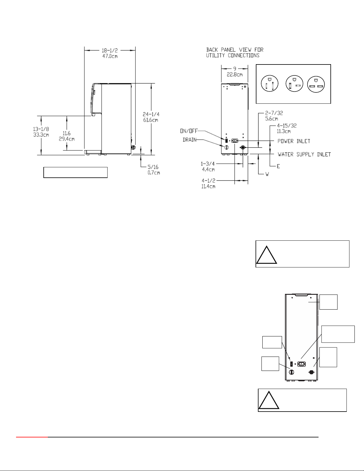
Dimensions & Utility Connections
Drawing # 1201.00001.00
Water inlet fitting: ¼ inch female pipe fitting
NEMA PLUG CONFIGURATION
G
W
NEMA 5-15P NEMA 5-20P NEMA 6-15P
G
W
Installation
The installation must comply with applicable federal, state, and local codes having jurisdiction at your location.
Utilize only qualified beverage equipment service technicians for installation.
A Service Company Directory may be found on our website, http://www.fetco.com.
Setup
1. Before placing the unit, verify that it will fit in the space intended for it, and that
!
Warning: Legs are to be adjusted
only to level the unit. Do not extend
them higher than necessary
the counter or table will support the weight of the HWD-2105 when filled.
2. When the unit is in position, use a bubble level to level it front to back and side
to side by adjusting the legs.
Water Connection
Back panel of HWD-2105
1. Water inlet is a ¼ inch ¼ inch male flare fitting.
2. Install a shut off valve near the unit to facilitate service.
3. Install a backflow prevention device, a spring loaded double check valve such as a
WATTS® SD-2 or SD-3, two models accepted by most zoning authorities. The
check valve should be as close to the water supply inlet as possible.
4. An inline water filter is highly recommended. It should be installed after the water
shutoff valve and in a position to facilitate filter replacement.
5. Flush the water supply line and filter before connecting it to the unit.
Power
Switch
6. Verify that the water line provides at least 1½ gpm (5.7lpm), and that the water
pressure is between 40-75 psig (276-517kPa). Use cold water only.
Tank
Drain
Electrical Connection
1. Check serial number plate for the maximum wattage and verify that the actual
voltage at the electrical outlet is compatible with the unit’s specifications.
2. Plug unit in. Note that the plug is NEMA 5-15P or NEMA 5-20P (domestic).
3. The temperature and water tank fill level are pre-set at the factory and there is
no need to turn off the heater during the installation process.
To prevent electrical shock, this
!
unit must be properly grounded.
The heating process will start automatically when the tank is filled enough to
cover the heating element
WARNING
-Do not plug in this equipment or attempt to operate without all covers in place and all screws fastened.
Warning:
Tank
Vent
ppliance Inlet
(attach power cord)
Water
Supply
Inlet
3

Final Setup-Fill and Initial Heating
optio
1. Turn on the incoming water supply line and inspect both inside and outside of
the unit for leaks in all fittings and tubes.
2. Plug the unit into the appropriate electrical outlet.
3. Turn on the unit’s main power switch (located on the back).
Screen one-the FETCO Home Screen will display.
4. Within 6 seconds, the water tank will begin filling until tank probe senses water
Screen two, the “FILLING” will display.
5. Water will cover heating element or when tank water is heating from cold,
Screen three-the “HEATING” Screen will display.
The upper and lower “Touch Function Selector” will not light.
6. After the water has reached the lowest of the four set temperatures, the lower
“Touch Function Selector” will light red color to signal that at least one
temperature range is READY
(The touch selector buttons will alternately dim and brighten when selection is not active)
7. The display will read the four temperature settings as the tank temperature
rises. More detailed operation information follows
8. The upper “Touch Function Selector” will light if one or more temperature level
is available during heating
9. Re- inspect for leaks.
Operating Instructions
1. Turn the main power switch on.
2. Touch the upper “Touch Function Selector”, tapping finger to scroll to select
3. When a temperature is enlarged and brightened - that temperature is available.
Touch the lower red selector to dispense hot water.
4. Maximum continuous “ON” is fifteen (15) seconds in a single activating touch
5. Maximum dispense is approximately 20 ounce/600 milliliter.
Approximately three full 15 second batches may be dispensed in succession.
6. Unit returns to inactive “Enabled Screen” if no water is dispensed in 3 seconds
7. Steam and condensation from the water tank is released into the vent
whenever the unit is on. Access the vent barbed fitting located on the upper
back to run gravity drain. For venting to a drain, tubing requirement is ¼” I.D.
(To prevent vacuum backflow, do not place discharge end of vent drain tube
into drain sump)
Operator Training
Review the operating procedures with everyone who will be using the unit.
Pay particular attention to the following areas:
1. Selecting and dispensing water at all four levels
2. How to change temperature settings (See page 7)
3. Scrolling and selecting temperatures and operating the hot water faucet.
Pay particular attention to the safety warnings. (See page 6 & 7)
4. Refer to cleaning procedures and drip tray, listed on the following page.
5. Show the location of the on/off switch, water shut off valve and the utility power
supply circuit breaker for the unit. (See page 3)
DISPENSE
ENABLED
SCREEN
Icon appears after
tank fill and
heating. At least
one temperature
is available for
dispensing
Upper Touch
Function Selector
scrolls the menu
selection option
Lower Touch
Function Selector
selects and
activates selected
n
4
The three primary screens for HWD-2105 start up
Home Screen
when power is
turned on.
(Three screens in
“Standby Mode”Controls inoperative)
Above-Screen One-FETCO Home Screen
Below-Screen Two
Hot Water Tank is
filling.
Upper and lower
Touch Function
Selectors will
disappear, dim, or
brighten while in
standby or while
filling or heating.
(Controls inoperative)
Hot Water Tank is
heating.
Icon appears from
first fill or during
reheating from an
unheated state or
depleted tank.
(Controls inoperative)
Above-Screen Three-HWD Status Screen
-HWD Status Screen
 Loading...