

Page 1

PRECISIO
Seen at Ideal Tools.
CS 50 EB
CS 50 EB Floor
Bedienungsanleitung 5 - 10
Operating Instructions 11 - 15
Mode demploi 16 - 21
Instrucciones de servicio 22 - 27
Istruzioni duso 28 - 33
Gebruiksaanwijzing 34 - 39
Bruksanvisning 40 - 44
Käyttöohje 45 - 49
Driftsvejledning 50 - 54
Bruksanvisning 55 - 59
Instruções de uso 60 - 65
Руководство по эксплуатации 66 - 71
Návod k obsluze 72 - 76
Instrukcja obs³ugi 77 - 82
Kezelési utasítás 83 - 87
464 688_005
ПдзгЯб лейфпхсгЯбт 88 - 93
Festool GmbH Wertstr. 20 D-73240 Wendlingen ( 07024/804-0
Page 2
Seen at Ideal Tools.
Page 3
Seen at Ideal Tools.
Page 4
Seen at Ideal Tools.
Page 5

1 Technical data
Seen at Ideal Tools.
Cutting depth at 90° / 45° 0 - 50 mm / 0 - 40 mm
Inclination -2° to 47°
max. drawing length 300 mm
Saw blade (diameter x cutting width) 190 x 2.6 mm
Idling speed 1600 - 4200 rpm
Power consumption 1200 W
Bench dimensions (length x width) 600 x 400 mm
Bench height with / without foldaway legs 900 mm / 375 mm
Weight without foldaway legs 19 kg
Weight of foldaway legs 2 kg
The specified illustrations can be found at the
beginning of the operating instructions.
2 Intended use
The PRECISIO is intended as a transportable
electric power tool for sawing wood, plastics,
board tools made of wood and materials similar
to wood. With the special saw blades for
aluminium offered by Festool, these machines
can also be used for sawing aluminium.
Materials containing asbestos must not be
processed. The user is liable for any damage
or accidents resulting from use not in
accordance with the intended use.
3 Before starting up, please observe
the following
3.1 Safety instructions
IMPORTANT! When electric power tools
are used, the following fundamental
safety measures are to be complied
with to protect against electric shocks
and the risks of injury and fire.
Read all of these instructions before
you use this electric power tool and
keep the safety instructions in a safe
place.
1. Keep your work area tidy
- Untidiness in work areas can lead to
accidents.
2. Take account of environmental
influences
- Do not expose electric power tools to rain.
- Do not use electric power tools in damp or
wet environments.
- Ensure that the work area is well lit.
- Do not use electric power tools where there
is a danger of fire or explosion.
3. Protect yourself against electric
shocks
- Avoid body contact with earthed parts (e.g.
pipes, radiators, electric cookers, cooling
devices).
4. Keep other people away
- Do not permit other people, in particular
children, to touch the electric power tool or
the power cable. Keep these people away
from your work area.
5. Store unused electric power tools in
a safe place
- Unused electric power tools should be stored
in a d r y pl a ce a t a c e rt a in h e ig h t o r in a l oc k ed
area, beyond the reach of children.
6. Do not overload your electric power
tool
- You work better and more safely within the
specified power range.
7. Use the right electric power tool
- No not use low-power machines for heavyduty work.
- Do not use the electric power tool for
purposes for which it is not intended. For
example, do not use a portable circular saw
to cut tree branches or billets of wood.
8. Wear suitable clothing
- Do not wear bulky clothing or jewellery; this
could be caught up in moving parts.
- When you are working outdoors, non-slip
shoes are recommended.
- If you have long hair, wear a hair net.
9. Use protective equipment
- Wear protective goggles
- For work that generates dust, wear a face
mask.
10. Connect the dust extraction facility
- If there are connections to dust extraction
and collection, ensure that these are correctly
connected and are used correctly.
11. Do not use the power cable for
purposes for which it is not intended
- Do not use the power cable to pull the mains
plug from the socket. Protect the power
cable against heat, oil and sharp edges.
11
Page 6

12. Secure the workpiece
Seen at Ideal Tools.
- If possible, use clamps or a vice to secure
the workpiece. This holds it more securely
than by hand.
13. Avoid abnormal body postures
- Ensure that you are standing securely and
keep your balance at all times.
14. Carefully maintain your tools
- Keep cutting tools sharp and clean in order
to be able to work better and more safely.
- Comply with the instructions for lubrication
and tool changes.
- Regularly check the connection cable of the
electric power tool. In the event of damage,
have it replaced by a recognised professional.
- Regularly check extension cables and replace
them if they are damaged.
- Keep the hand grips dry, clean and free of oil
and grease.
15. Pull the mains plug from the socket
- If the electric power tool is not being used,
prior to maintenance and when changing
tools, e.g. saw blade, drill bit, router bit.
16. Do not leave tool keys in the tool
- Before switching on, check that the key and
adjusting tools have been removed.
17. Avoid inadvertent start-ups
- Make sure that the switch is off when you
insert the plug in the socket.
18. Use extension cables for outdoors
- Outdoors, use only approved and
appropriately coded extension cables.
19. Pay attention
- Take care of what you do. Work sensibly. Do
not use electric power tools when you lack
concentration.
20. Check the electric power tool for
damage
- Before continuing to use the electric power
tool, protection devices or slightly damaged
parts must be carefully examined to ensure
that they function perfectly and in accordance
with their intended purpose.
- Check whether moving parts work perfectly
and that they do not jam, or whether parts
are damaged. All parts must be correctly fitted
and all conditions met to ensure perfect
operation of the electric power tool.
- Damaged protection devices and parts must
be properly repaired or replaced by a
recognised specialist workshop, unless otherwise specified in the operating instructions.
- Damaged switches must be replaced in a
customer service workshop.
- Do not use any electric power tools on which
the switch cannot be switched on and off.
21. IMPORTANT!
- The use of other tools and accessories can
represent a risk of injury.
22. Have your electric power tool repaired
by a qualified electrician
- This electric power tool complies with the
relevant safety regulations. Repairs may only
be carried out by a qualified electrician using
original spare parts; otherwise, accidents
involving the user can occur.
23. Machine-specific safety instructions
- Deformed or cracked saw blades and saw
blades with blunt or broken cutting edges
must not be used.
- The maximum speed specified on the tool is
to be complied with.
- The tool must be suitable for the material to
be processed.
- Saw blades made of High Speed Steel (HSS
steel) must not be used.
- The tools must be transported and stored in
a suitable container
- Wear suitable personal protection equipment:
Ear protection to reduce the risk of
damaging your hearing
Protective goggles
Face mask to reduce the risk of inhaling
harmful dust
Protective gloves when handling tools and
coarse materials
- To minimise the creation of dust, the machine
is to be connected to a suitable dust
extractor, and all the elements for dust
collection (extractor hood etc.) must be
properly set.
- When sawing wood, the machine is to be
connected to a dust extractor complying with
EN 60335-2-69, dust category M.
- To minimise noise development, the tool must
be sharpened and all elements for noise
reduction (covers etc.) must be properly set.
- The machine may only be used if all protection
devices are in the appropriate positions and
if the machine is in good condition and has
been properly serviced.
- Faults in the machine, including the separating
protection devices or in the tools, must be
reported immediately on discovery to
maintenance personnel. The machine may
only be used again once the faults have been
rectified.
- Rebating or grooving are only permitted with
a suitable protection device, e.g. a tunnel
protection device over the saw table.
- Circular saws must not be used for slotting
(groove completed in the workpiece).
- The upper protective hood may not be used
as a carrying handle!
- During transport of the machine, the upper
protective cover must cover the upper
section of the saw blade.
- Long workpieces are to be supported by a
suitable setup so that they lie horizontally.
12
Page 7

3.2 Noise and vibration information
Seen at Ideal Tools.
Sound pressure level
Idling / processing 84 / 90 dB(A)
Noise power level
Idling / processing 97 / 103 dB(A)
Measurement tolerance K = 4 dB
Wear ear protection!
3.3 Residual risks
In spite of compliance with all relevant design
regulations, dangers may still present themselves when the machine is operated, e.g.:
- Workpiece parts being thrown off,
- Parts of damaged tools being thrown off,
- Noise emission,
- Sawdust emission.
4 Setting up, commissioning
Ensure that the floor around the machine is
level, in good condition and free of loose
objects (e.g. chips and offcuts).
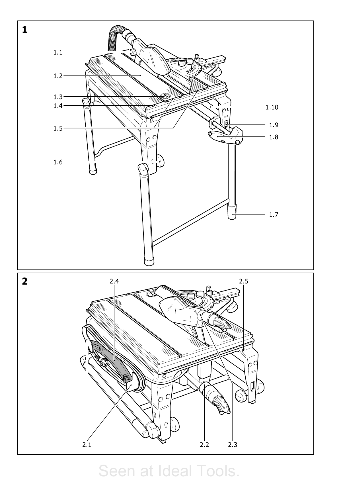
4.1 Mounting the machine
The machine can be set up with or without the
legs folded out (Fig. 1 and 2) (the Floor
model does not include folding legs).
To fold out the legs, open the four rotary knobs
(1.6) as far as they will go. After folding out
the legs, retighten the four rotary knobs.
So that the machine stands securely, the length
of one of the legs can be changed by turning
the cap on the end (1.7).
4.2 Applications
The machine can be used as a bench-mounted
circular saw or as a circular trimming saw.
a) Bench-mounted circular saw
(Fig. 1)
- Set the switch (1.9) to the lower position.
- Swing the hand grip (1.8) downwards, and
use the hand grip to pull the saw unit
forwards until it locks into place.
The saw unit is now in a central bench position
and the machine can be used as a benchmounted circular saw.
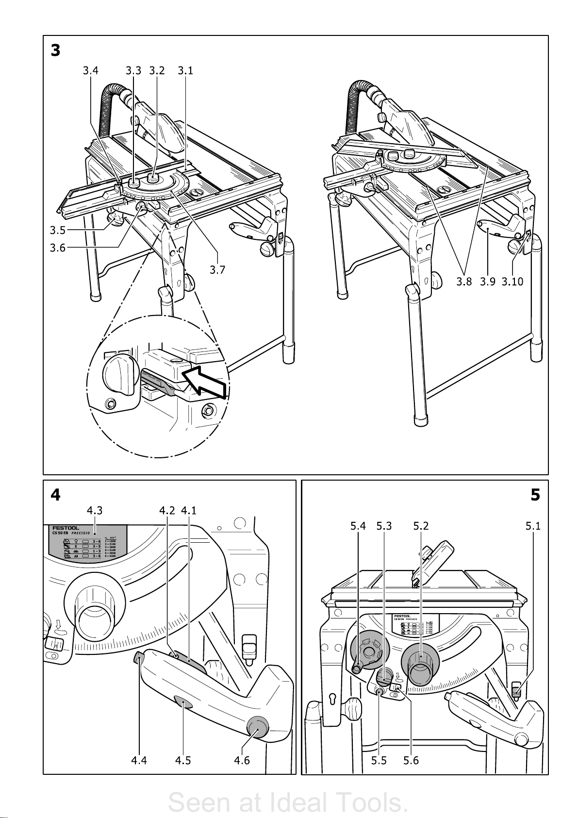
b) Circu l a r t r i mmi n g sa w (Fi g . 3)
- Set the switch (3.10) to the upper position.
If the hand grip (3.9) is swung downwards, it
can be used to move the saw unit backwards
and forwards for drawing cuts. The backward
movement is supported by spring force.
4.3 Dust extraction
The PRECISIO has two extraction
connections: the upper protective
cover (2.3) with a diameter of 27 mm,
and the lower protective cover (2.2)
with a diameter of 35 mm.
The extraction set CS 70 AB (488 292, included
in scope of delivery for CS 50 EB) joins both
of the extraction connections so that a Festool
extractor module can be connected.
4.4 Power supply and start-up
The mains voltage must correspond to the
specification on the rating plate.
On account of the performance capability of
the motor, we recommend a 16 A fuse.
To switch on, press the ON/OFF switch (4.1)
and the locking switch (4.4) simultaneously.
The machine runs as long as the ON/OFF switch
is pressed.
For continuous operation after switching on,
first press the ON/OFF switch (4.1) and then
let go of the locking switch (4.4). To switch off
continuous operation, either press the ON/OFF
switch again and let it go or press the red switch
(4.6). To protect against unauthorised
activation, a shackle type connector can be
inserted in the hole (4.2) of the ON/OFF switch.
5 Electronics
The machine has full-wave electronics
with the following features:
5.1 Smooth start-up
The smooth start-up ensures the router starts
up jolt-free.
5.2 Speed adjustment
You can regulate the speed steplessly between
1600 and 4200 min-1 using the adjusting
wheel (4.5). This enables you to optimise the
cutting speed to suit the material (4.3).
The pre-selected speed remains constant
whether the machine is in operation or in neutral position.
5.3 Overload protection
In the event of an extreme overload of the
machine, the power supply is reduced. If the
motor is blocked for a longer period, the power
supply is interrupted completely. After removal
of the blockage or switching on again, the
machine is operational once again.
5.4 Temperature protection
If the motor temperature becomes too high,
the power supply and speed are reduced. The
machine then only runs with reduced power
to enable rapid cooling by means of the motor
ventilation. After cooling down, the machine
accelerates again automatically.
5.5 Brake
After switching-off the tool, the saw blade is
electronically brought to a standstill in 1.5 2
seconds (only for 230 V - 240 V configuration).
5.6 Restart protection
The built-in undervoltage release prevents that
the machine restarts on its own in the continuous operation mode following a power cut. In
this case, the machine must first be switched
off and then on again.
13
Page 8

6 Machine settings
Seen at Ideal Tools.
Prior to any setting, maintenance or
repair, pull the mains plug!
To make setting easier, the saw unit can be
locked in the front position (Fig. 5): pull the
saw unit forwards as far as it will go and place
the switch (5.1) in the lower position.
The machine must not be used in the
front position!
6.1 Cutting depth
The cutting depth can be set steplessly (0 50 mm with 90° position of the saw blade) by
turning the crank handle (5.4).
6.2 Mitre
The saw blade can be pivoted between 0° and
45°:
- Open the rotary knob (5.3).
- Se t th e mit r e us ing th e sc a l e (5.6 ) by t u r ning
the handle (5.2).
- Close the rotary knob (5.3).
For exact fitting work (relief cutting on the
bordering), the saw blade can be pivoted 2°
beyond the two end positions. To do so, the
button (5.5) is pressed in the end position;
the saw blade can then be pivoted up to -2°
or 47°. On pivoting back, both end positions
are active once again.
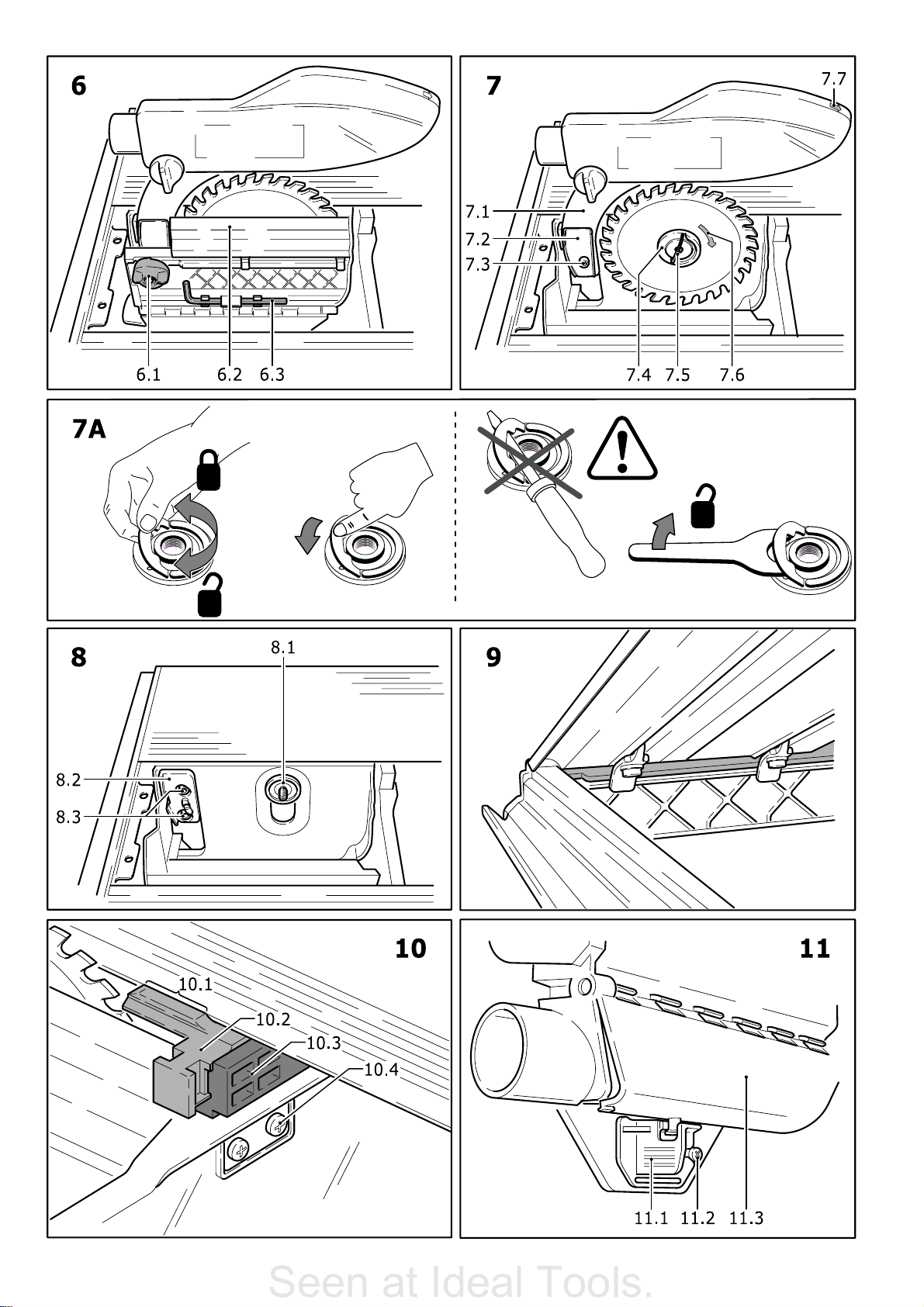
6.3 Changing tools
Safety Instructions Fast-Fix
Tension Nut (see Fig. 7 A).
After tensioning, close the handle bow.
Only tighten or loosen the Fast-Fix
Tension Nut by hand. Under no
circumstances use the handle bow with
aid of screwdrivers, pliers, or other
tools for tightening or loosening.
If the nut cannot be loosened by hand,
only use a pin-type face spanner for
support.
Never continue to use the Fast-Fix nut,
in case the handle bow is loose or
damaged.
Due to the special shank, only the saw
blades offered by Festool for this
machine may be used.
- Open the locking mechanism (1.3) and
remove the bench insert (1.2) upwards
- Open the locking mechanism (6.1) and swing
the saw blade cover (6.2) down. This
automatically locks the tool spindle
- Shift the lever (7.5) and turn clockwise (left-
hand thread) to open the Fast-Fix clamp
(7.4)
- Change the tool. In doing so, bear in mind:
The Fast-Fix clamp (7.4), flange (8.1) and
saw blade must be clean
The direction of rotation on the saw blade
(7.6) must match the direction of rotation
of the machine (7.7)
Place the saw blade on the centre of the
flange (8.1) and turn until the contour of
the flange and the saw blade hole lock.
- Firmly tighten the Fast-Fix clamp (7.4)
anticlockwise; shift the lever (7.5)
- Swing the saw blade cover (6.2) upwards
and close the locking mechanism (6.1)
- Insert the bench insert with the rear edge
first (see Fig. 9) and close the locking
mechanism (1.3).
6.4 Setting the riving knife
The spacer wedge (7.1) is to be set in such a
way t h at the gap to the c h uck of the saw bla d e
is 3 to 5 mm.
- Use the Allen key (6.3) to remove the screw
(7.3) and take it out together with the
clamping element (7.2),
- After both of the screws (8.3) have been
opened, the guide element (8.2) can be
shifted vertically to set the gap between the
spacer wedge and saw blade.
- After completion of the setting, fit the spacer
wedge and clamping element again and
tighten all screws.
6.5 Guide
As shown in Fig. 3, the supplied guide can be
secured to all four sides of the machine.
The guide offers the following adjustment
options:
Adjustment parallel to the bench edge - open
the rotary knob (3.5).
Adjustment vertical to the bench edge - open
the rotary knob (3.6).
Adjustment of the sliding fence (3.1) in a lon-
gitudinal direction - open the rotary knob
(3.2). The sliding fence can be clamped onto
the holder in a low position for thin
workpieces (Fig. 1), or in a high position for
thick workpieces (Fig. 3).
Angle adjustment using the scale (3.7) - open
the rotary knob (3.3) and raise the fixing pin
(3.4). The rotating fixing pin locks into place
in the most common angle positions.
This means that the guide can be used as a
parallel guide (Fig. 1) or as a cross guide or
angle guide (Fig. 3).
Prior to all work, make sure that all
rotary knobs of the guide are
tightened. The guide may only be used
in a fixed position and not to shift the
workpiece.
6.6 Scale for cutting width
The two scales (1.5) specify the cutting width
for longitudinal cuts.
If required, the scales can be realigned after
opening the screws (1.4).
6.7 Mounting the splinterguard
The splinterguard (10.2) prevents breakouts
on the lower cutting edge of the workpiece.
The splinterguard can be used for all mitres,
but a separate splinterguard must be fitted and
sawn in for each angle:
14
Page 9

- Set saw blade to minimum cutting depth.
Seen at Ideal Tools.
- Open the locking mechanism (1.3) and
remove the bench insert (1.2) upwards.
- Open the locking mechanism (6.1) and swing
the saw blade cover (6.2) down. This
automatically locks the tool spindle.
- Push splinterguard (10.2) from the side into
the holder (10.3) up to the stop.
- Swing the saw blade cover (6.2) upwards
and close the locking mechanism (6.1).
- Insert the bench insert with the rear edge
first (see Fig. 9) and close the locking
mechanism (1.3).
- Switch on tool and slowly move the saw blade
up to the maximum cutting depth this cuts
the splinterguard to shape.
For a optimum function the raised part (10.1)
of the splinterguard should protrude slightly
(approx. 0.3 mm) above the surface of the
base runner. For this purpose the height of the
holder (10.3) can be adjusted after releasing
both screws (10.4).
interrupted automatically and the router comes
to a standstill.
Service your machine regularly to ensure that
it functions properly:
- Vacuum off dust deposits
- Keep the guide bars (1.10) clean and grease
them regularly
- A worn or damaged bench insert is to be
replaced
- The slider (11.1) can be used to open the
hatch (11.3) to enable removal of cutting
residues from the lower protective cover. In
order to remove larger deposits, the hatch
can be opened completely by removing the
screw (11.2). Prior to commissioning, the
hatch must be closed again!
- On completion of your work, wind the power
cable around the holders (2.1).
- A damper means that the saw unit runs back
evenly across the entire drawing length. If
this is not the case, the damper can be
adjusted through the hole (2.5).
7 Working with the machine
When working with the machine,
comply with all safety instructions.
Adjust the protective hood so that it rests on
the workpiece and clamp it in this position with
the knob (1.11).
7.1 Bench-mounted circular saw
Use the guide as a parallel guide (Fig. 1) to
guide the workpiece. The cutting width can be
set using the scales (1.5). Guide the workpiece
into place by hand. Use the workpiece holder
(2.4) to guide the workpiece safety past the
saw blade. When not in use, place the workpiece holder in the storage compartment (2.1).
7.2 Circular trimming saw
Use the guide as a cross guide or as an angle
guide (Fig. 3) to apply and secure the workpiece. Alternatively, clamps (489 570) can be
inserted in the grooves (3.8) to secure the
workpiece. Perform the sawing cut by swinging
the hand grip (3.9) downwards and using the
hand grip to pull the saw unit forwards.
After making the sawing cut, move the saw
unit right back again into its initial position before
you take the workpiece from the guide.
8 Maintenance and care
Prior to any setting, maintenance or
repair, pull the mains plug!
All maintenance and repair work which
requires the motor casing to be opened
may only be carried out by an
authorised service centre.
The routers are fitted with special carbon
brushes with automatic-switch-off. When the
brushes reach their wear limit the current is
9 Accessories, tools
Festool offers a comprehensive range of
accessories that ensures versatile and effective
deployment of your machine, e.g. table
widening, table lengthening, sliding table, mitre
guide, transport rollers, extraction set.
In order to be able to saw different materials
quickly and cleanly, Festool offers saw blades
that are specially designed for your machine.
The accessory and tool order number can be
found in the Festool catalogue or on the
Internet under www.festool.com.
10 Warranty
Our equipment is under warranty for at least
12 months with regard to material or
production faults in accordance with national
legislation. In the EU countries, the warranty
period is 24 months (an invoice or delivery
note is required as proof of purchase).
Damage resulting from, in particular, normal
wear and tear, overloading, improper handling,
or caused by the user or other damage caused
by not following the operating instructions, or
any fault acknowledged at the time of
purchase, is not covered by the warranty.
Complaints will only be acknowledged if the
equipment has not been dismantled before
being sent back to the suppliers or to an
authorised Festool customer support workshop. Store the operating instructions, safety
notes, spare parts list and proof of purchase
in a safe place. In addition, the manufacturers
current warranty conditions apply.
Note
We reserve the right to make changes to the
technical data contained in this information as
a result of ongoing research and development
work.
15
Page 10

EG-Konformitätserklärung. Wir erklären in alleiniger
Seen at Ideal Tools.
Verantwortung, dass dieses Produkt mit den
folgenden Normen oder normativen Dokumenten
übereinstimmt:
EN 61 029, EN 55 014, EN 61 000 gemäß den Bestimmungen
der Richtlinien 98/37/EG, 89/336/EWG.
CE-Konformitetserklæring. Vi erklærer på eget
ansvar at dette produktet er i overensstemmelse med
følgende normer eller normative dokumenter: EN 61 029,
EN 55 014, EN 61 000 i henhold til bestemmelsene i direktivene
98/37/EF, 89/336/EØF.
EC-Declaration of Conformity: We declare at our sole
responsibility that this product is in conformity with
the following standards or standardised documents:
EN 61 029, EN 55 014, EN 61 000 in accordance with the
regulations 98/37/EC, 89/336/EEC.
CE-Déclaration de conformité communautaire. Nous
déclarons sous notre propre responsabilité que ce
produit est conforme aux normes ou documents de
normalisation suivants: EN 61 029, EN 55 014, EN 61 000
conformément aux prescriptions des directives
98/37/CE, 89/336/CEE.
CE-Declaración de conformidad. Declaramos bajo
nuestra exclusiva responsabilidad que este
producto corresponde a las siguientes normas o documentos
normalizados: EN 61 029, EN 55 014, EN 61 000 conforme a
las prescripciones estipuladas en las directrices 98/37/CE,
89/336/CEE.
CE-Dichiarazione di conformità. Dichiariamo sotto
la nostra esclusiva responsabilità che il presente
prodotto è conforme alle norme e ai documenti normativi
seguenti: EN 61 029, EN 55 014, EN 61 000 conformemente
alle normative delle direttive 98/37/CE, 89/336/CEE.
CE-Declaração de conformidade: Declaramos, sob
a nossa exclusiva responsabilidade, que este
produto corresponde às normas ou aos documentos
normativos citados a seguir: EN 61 029, EN 55 014,
EN 61 000 segundo as disposições das directivas
98/37/CE, 89/336/CEE.
Заявление о конформности СЕ. Мы заявляем в
единоличной ответственности, что данное изделие
соответствует требованиям следующих стандартов или
нормативов: EN 61 029, EN 55 014, EN 61 000 в соответствии
с постановлениями директив ЕС 98/37, ЕЭС 89/336.
Prohláení o souladu s normami CE. Prohlaujeme
na vlastní zodpovìdnost, e tento výrobek odpovídá
následujícím normám nebo normativním dokumentùm:
EN 61 029, EN 55 014, EN 61 000 v souladu s ustanoveními
smìrnic 98/37/EHS, 89/336/EHS.
Owiadczenie o zgodnoci CE. Niniejszym
owiadczamy z ca³¹ odpowiedzialnoci¹, ¿e wyrób
ten odpowiada nastêpuj¹cym normom wzglêdnie dokumentom
normatywnym: EN 61 029, EN 55 014, EN 61 000 zgodnie z
postanowieniami wytycznych 98/37/EG, 89/336/EWG.
EG-conformiteitsverklaring. Wij verklaren op eigen
verantwoordelijkheid dat dit produkt voldoet aan de
volgende normen of normatieve documenten. EN 61 029,
EN 55 014, EN 61 000 conform de richtlijnen 98/37/EG,
89/36/EEG.
EG-konformitetsförklaring. Vi förklarar i eget ansvar,
att denna produkt stämmer överens med följande
normer och normativa dokument: EN 61 029, EN 55 014,
EN 61 000 enligt bestämmelserna i direktiven 98/37/EG,
89/336/EEG.
EY-standardinmukaisuusvakuutus. Vakuutamme
yksinvastuullisina, että tuote on seuraavien
standardien ja normatiivisten ohjeiden mukainen: EN 61 029,
EN 55 014, EN 61 000 direktiivien 98/37/EY, 89/336/EY
määräysten mukaan.
EF-konformitetserklæring: Vi erklærer at have alene
ansvaret for, at dette produkt er i overensstemmelse
med de følgende normer eller normative dokumenter:
EN 61 029, EN 55 014, EN 61 000 i henhold til bestemmelserne
af direktiverne 98/37/EF, 89/336/EØF.
CE-konformitás-nyilatkozat.Kizárólagos
felelõsségvállalás mellett ezennel tanúsítjuk, hogy
a jelen termék megfelel az alábbi szabványoknak ill.
szabványdokumentációnak: EN 61 029, EN 55 014,
EN 61 000 a 98/37EG, 89/336/EWG irányvonalak
rendelkezései szerint.
Дзлщуз ухммьсцщузт ЕК. Ме бнЬлзшз фзт
ухнплйкЮт ехиэнзт дзлюнпхме, ьфй фп рбсьн рспйьн
ухмцщнеЯ ме фб рбсбкЬфщ рсьфхрб кбй ме фб
рсьфхрб рпх бнбцЭспнфбй уфб учефйкЬ Эггсбцб ЕН 61 029,
ЕН 55 014, EN 61 000 уэмцщнб ме фпхт кбнпнйумпэт
98/37ЕК, 89/336/ЕПК.
Leitung Forschung und Entwicklung
Management Research and Development
Direction de recherce et développement
Festool GmbH
Wertstr. 20
D-73240 Wendlingen
Dr. Johannes Steimel
449 699/170703
Page 11

Festool GmbH
Seen at Ideal Tools.
Postfach 1163
D-73236 Wendlingen
Wertstraße 20
D-73240 Wendlingen
) (07024) 804-0
Fax (07024) 804-608
http://www.festool.com
 Loading...