

Page 1

Instruction manual
Page 3 - 12
IMPORTANT: Read all instructions before using.
Guide d’utilisation
Page 13 - 23
IMPORTANT: Lire toutes les instructions avant de démarrer
les travaux.
Manual de instrucciones
Pagina 24 - 34
IMPORTANTE: Lea todas las instrucciones antes de
usar.
458 359_005
Instruction manual
Guide d’utilisation
Manual de instrucciones
HL 850 E
Page 2

2
Page 3

Contents
General safety rules 3
Planer Safety rules 4
Technical data 5
Symbols 5
Functional description 5
Use for intended purpose 5
Electrical connection and operation 6
Extension cable 6
Electronic control 6
Machine settings 7
Chip thickness adjustment 7
Planer heads and spiral cutters 8
Fitting the guides 8
Dust extraction and chip ejection 9
Working with the machine 9
Rebating 10
Chamfering 10
Bench-mounted operation 10
Rustic planer heads (accessories) 11
Systainer 11
Maintenance and service 11
Accessories, tools 12
Warranty 12
General safety rules
Read all safety warnings
and all instructions. Failure to follow the
warnings and instructions may result in
electric shock, fi re and/or serious injury.
Save all warnings and instructions for
future reference.
The term “power tool” in the warnings refers
to your mains-operated (corded) power tool
or battery-operated (cordless) power tool.
1 WORK AREA SAFETY
a) Keep work area clean and well lit.
Cluttered and dark areas invite accidents.
b) Do not operate power tools in explosive
atmospheres, such as in the presence of
fl ammable liquids, gases or dust. Power
tools create sparks which may ignite the dust
or fumes.
c) Keep children and bystanders away
while operating a power tool. Distractions
can cause you to lose control.
2 ELECTRICAL SAFETY
a) Power tool plugs must match the
outlet. Never modify the plug in any
way. Do not use any adapter plugs
with earthed (grounded) power tools.
Unmodifi ed plugs and matching outlets will
reduce risk of electric shock.
b) Avoid body contact with earthed
or grounded surfaces, such as pipes,
radiators, ranges and refrigerators.
There is an increased risk of electric shock if
your body is earthed or grounded.
c) Do not expose power tools to rain or
wet conditions. Water entering a power tool
will increase the risk of electric shock.
d) Do not abuse the cord. Never use the
cord for carrying, pulling or unplugging
the power tool. Keep cord away from
heat, oil, sharp edges or moving parts.
Damaged or entangled cords increase the risk
of electric shock.
e) When operating a power tool outdoors,
use an extension cord suitable for
outdoor use. Use of a cord suitable for
outdoor use reduces the risk of electric shock.
f) If operating a power tool in a damp
location is unavoidable, use a residual
current device (RCD) protected supply.
Use of an RCD reduces the risk of electric shock.
3 PERSONAL SAFETY
a) Stay alert, watch what you are doing
and use common sense when operating a
power tool. Do not use a power tool while
you are tired or under the infl uence of
drugs, alcohol or medication. A moment of
inattention while operating power tools may
result in serious personal injury.
b) Use personal protective equipment.
Always wear eye protection. Protective
equipment such as dust mask, non skid safety
shoes, hard hat, or hearing protection used
for appropriate conditions will reduce personal
injuries.
c) Prevent unintentional starting. Ensure
the switch is in the off-position before
connecting to power source and/or
battery pack, picking up or carrying the
tool. Carrying power tools with your fi nger
on the switch or energising power tools that
have the switch on invites accidents.
3
Page 4

d) Remove any adjusting key or wrench
before turning the power tool on. A wrench
or a key left attached to a rotating part of
the power tool may result in personal injury.
e) Do not overreach. Keep proper footing
and balance at all times. This enables
better control of the power tool in unexpected
situations.
f) Dress properly. Do not wear loose
clothing or jewellery. Keep your hair,
clothing and gloves away from moving
parts. Loose clothes, jewellery or long hair
can be caught in moving parts.
g) If devices are provided for the
connection of dust extraction and
collection facilities, ensure these are
connected and properly used. Use of dust
collection can reduce dust-related hazards.
4 POWER TOOL USE AND CARE
a) Do not force the power tool. Use the
correct power tool for your application.
The correct power tool will do the job
better and safer at the rate for which it was
designed.
b) Do not use the power tool if the switch
does not turn it on and off. Any power tool
that cannot be controlled with the switch is
dangerous and must be repaired.
c) Disconnect the plug from the power
source and/or battery pack from
the power tool before making any
adjustments, changing accessories, or
storing power tools. Such preventive safety
measures reduce the risk of starting the power
tool accidentally.
d) Store idle power tools out of the reach
of children and do not allow persons
unfamiliar with the power tool or these
instructions to operate the power tool.
Power tools are dangerous in the hands of
untrained users.
e) Maintain power tools. Check for
misalignment or binding of moving
parts, breakage of parts and any other
condition that may affect the power
tool‘s operation. If damaged, have the
power tool repaired before use. Many
accidents are caused by poorly maintained
power tools.
f) Keep cutting tools sharp and clean.
Properly maintained cutting tools with sharp
cutting edges are less likely to bind and are
easier to control.
g) Use the power tool, accessories and
tool bits etc. in accordance with these
instructions taking into account the
working conditions and the work to
be performed. Use of the power tool for
operations different from those intended could
result in a hazardous situation.
5 SERVICE
a) Have your power tool serviced by
a qualified repair person using only
identical replacement parts. This will
ensure that the safety of the power tool is
maintained.
Planer Safety rules
Wait for the cutter to stop before –
setting the tool down. An exposed cutter
may engage the surface leading to possible
loss of control and serious injury.
Use clamps or another practical way to –
secure and support the workpiece to a
stable platform. Holding the work by hand
or against your body leaves it unstable and
may lead to loss of controll.
TO REDUCE THE RISK OF INJURY,
USER MUST READ INSTRUCTION MANUAL.
Various dust created by power
sanding, sawing, grinding, drilling and other
construction activities contains chemicals
known (to the State of California) to cause
cancer, birth defects or other reproductive
harm. Some examples of these chemicals
are:
• Lead from lead-based paints,
• Crystalline silica from bricks and cement and
other masonry products,
• Arsenic and chromium from chemically-treated
lumber.
The risk from these exposures varies,
depending on how often you do this type of
work.
To reduce your exposure to these
chemicals work in a well ventilated area and use approved safety
equipment, such as dust masks
that are specially designed to fi lter
out microscopic particles.
4
Page 5

Technical data
Wattage: 850 W
No load speed: 10 000 rpm
Plane width 82 mm (3.2 in.)
Chip thickness 0 - 3.5 mm (0 - 0.14 in.)
Rebate depth unlimited
Weight 3.9 kg (8.6 lbs)
Safety standard:
/ II acc. to
UL 745, CSA C22.2 No. 745
Symbols
Warning of general danger
Read the Operating Instructions/Notes!
V volts
A amperes
Hz hertz
W watt
~ alternating current
n
no load speed
0
Class II Construction
rpm revolutions per minute
Functional description
1.21.41.6 1.11.31.7 1.5
1.8
1.1 Lock off button
1.2 On/Off switch
1.3 Shavings ejector
1.4 Shift lever for shavings ejector
1.5 Spindle stop
1.6 Interlock for cutting depth adjustment
1.7 Supplementary handle / cutting depth
adjustment
1.8 Parking device
Use for intended purpose
The HL 850 E planer together with the available
Festool accessories is designed for processing
wood, soft plastics and similar materials.
The user shall be liable for damages
and accidents due to incorrect use.
5
Page 6

Electrical connec-
tion and operation
The supply voltage must comply with the voltage given on the ratings plate.
The switch (1.2) is used as an on/off switch.
For your safety this is equipped with a switchon interlock (1.1 ). In order to run the planer
the switch-on interlock must fi rst be pressed
and then the switch.
Extension cable
If an extension cable is required, it must have
a suffi cient cross-section so as to prevent an
excessive drop in voltage or overheating. An
excessive drop in voltage reduces the output
and can lead to failure of the motor. The table
shows the correct size to use, depending on
cord length and tool‘s ampere rating. Use only
U.L. and CSA listed extension cables. Never
use two extension cables together. Instead,
use one long one.
Total Extension Cord
Lenght (feed)
Cord size (AWG) 18 16 14 12
Note: The lower the A.W.G. number, the
stronger the cable.
25 50 100 150
Electronic control
The devices are fi tted with a full-wave elec-
tronic control with the following functions:
Smooth start-up
The electronically-controlled smooth startup ensures that the machine starts without
jolts.
Idling speed
The electronic circuit limits the idling speed.
This means that the noise level also remains
low during idling.
Constant speed
The speed of the planer shaft is electronically
regulated to a constant value, thus also providing a constant cutting speed under load.
Temperature protection
Extreme overload in continuous running will
cause the motor to overheat. An electronic
6
Page 7
temperature monitoring device is fi tted to
provide protection against overheating (burning-out of the motor). The electronic safety
device switches off the motor before a critical
motor temperature is reached. After a cooling
period of approx. 3-5 minutes, the machine
is once again ready for use at full load. If the
machine is kept running (idling), the cooling
period is reduced.
Do not work with the planer if the electronic
control is defective, since this may lead to excessive speeds. A defect in the electronic control is indicated by the absence of a smooth
run-up, a higher noise level at idle or the fact
that no speed control is possible.
Machine settings
Always disconnect the plug from
the power supply before making any adjustments to the machine or installing or removing any accessory!
2.3
+
-
2.2 2.1
0.8
0.6
0.4
0.2
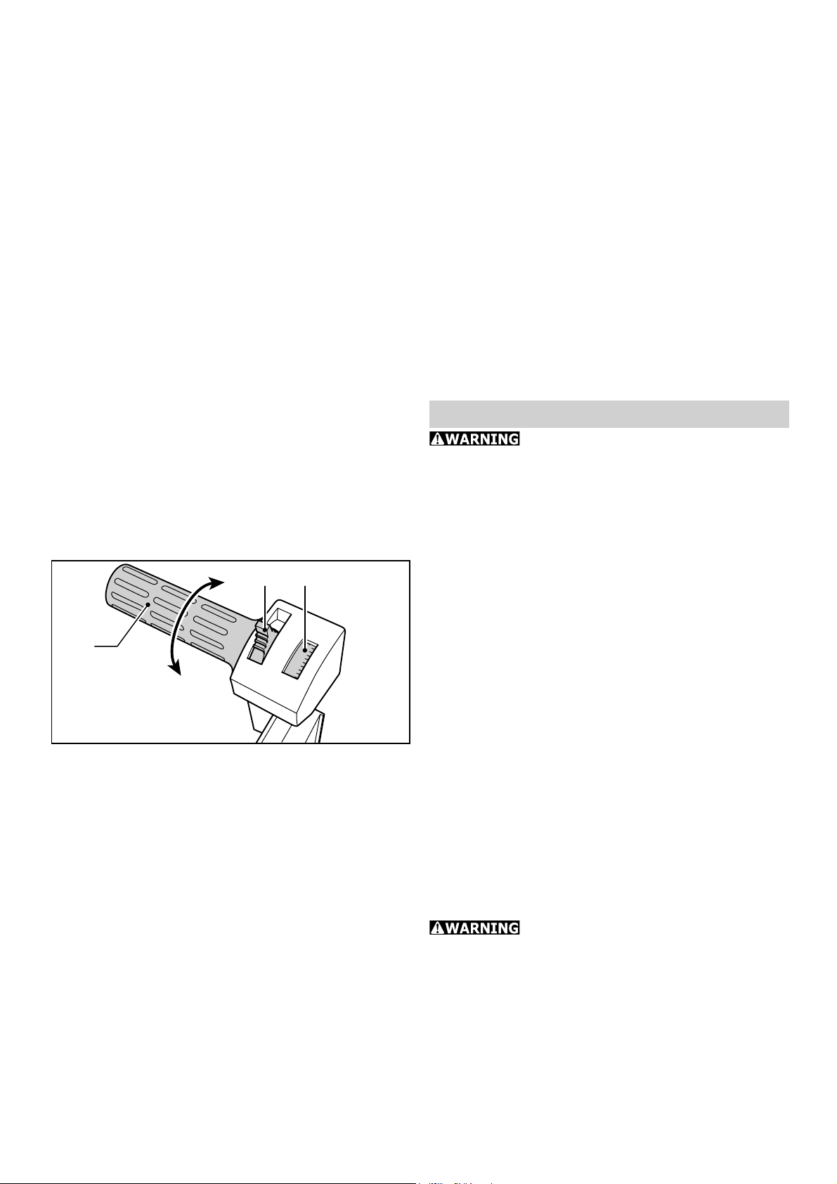
Chip thickness adjustment
After the interlock (2.2) has been released by
pushing it backward, the chip thickness can be
infi nitely adjusted between 0 mm and 3.5 mm
by turning the supplementary handle (2.3).
The chip thickness which has been set can be
read in the scale window (2.1). One division
corresponds to a chip removal of 0.1 mm.
If a constant chip thickness is to be set the
interlock must be pressed forward again after
the chip thickness has been adjusted. If the
chip thickness has to be varied during operation (fi tting work) the interlock should be left
open.
The supplementary handle can be turned
beyond the 0 mm mark to reach the P (=
Park) position, in which the spiral cutter is
completely retracted. This is, however, not
the case with the rustic planer heads.
Always ensure, therefore, that
when setting the machine down on a surface
the parking device (1.8) at the end of the
planer platen is correctly extended.
7
Page 8
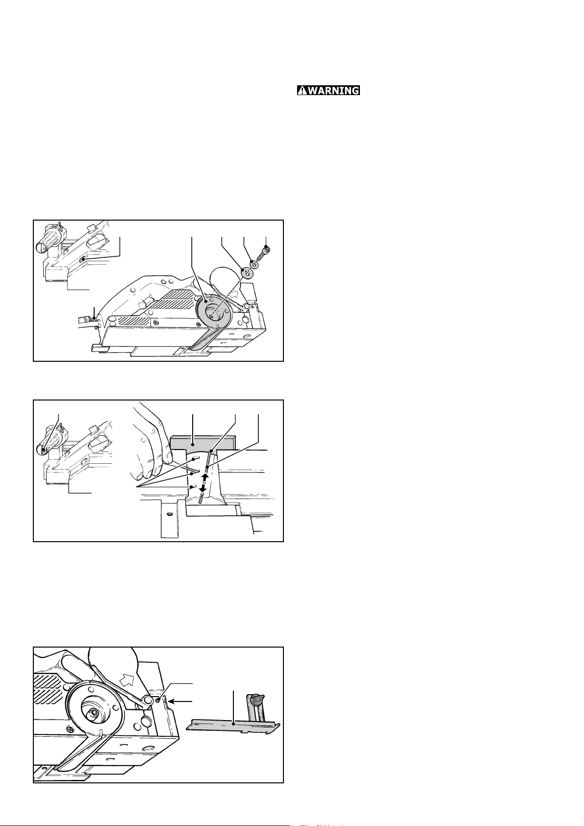
3.6
3.33.43.5 3.2
3.1
Planer heads and spi-
ral cutters
Use only cutters which are sharp
and undamaged. Blunt cutters increase the
danger of kick-back and reduce the planing
quality obtained.
The planer is equipped with planer head HK
82 SD as standard series. The planer head
has inclined, fi tted cutters, which is why the
cutters cannot be reground.
a) Changing the planer head
Use the spindle stop (3.5) to lock the planer
shaft and unscrew the allen bolt (3.1) from
the planer head (3.4) using the allen key
(3.6). Remove the planer head from the
planer shaft.
Before fi tting the new planer head clean the
planer shaft to remove any dust residues.
The planer head can be fi tted to the planer
shaft in reverse order using the clamping
fl ange (3.3), washer (3.2) and allen bolt
(3.6).
4.5
b) Changing the planer blade
4.2 4.3 4.44.1
Use the allen key (4.1) to loosen the three
allen bolts (4.5) in the planer head until the
planer blade can be removed.
Before the new blade is fi tted the cutter slot
must be cleaned. This ensures that the cutter is automatically correctly adjusted after
fi tting.
Push the new planer blade (4.4) into the
groove in the tool carrier with the labelled
side facing towards the rear planer platen.
Before you retighten the clamping screws use
a ruler (4.2) to align the blade in such a way
that its face lies fl ush with the front and rear
planer platen (4.3). Finally tighten fi rst the
centre clamping screw and then two outer
clamping screws.
Fitting the guides
The scope of delivery of the planer includes a
5.2
5.3
5.1
rebating depth guide and a parallel guide.
a) Rebating depth guide
The rebating depth guide (5.1) is mounted
in the threaded hole (5.2) on the front right
of the machine. The stop can be infi nitely
adjusted to between 0 mm and 30 mm in accordance with the scale. The rebating depth
8
Page 9

7.1
7.2
7.3
5.2
5.3
5.1
7.6
7.5
7.4
which has been set can be read against the
notch (5.3) in the housing.
b) Parallel guide
The parallel guide (6.2) is fi tted in the threaded
hole (6.1) next to the rear planer platen .
This same point can be used to mount the
swivelling angle guide WA-HL, available as
an accessory.
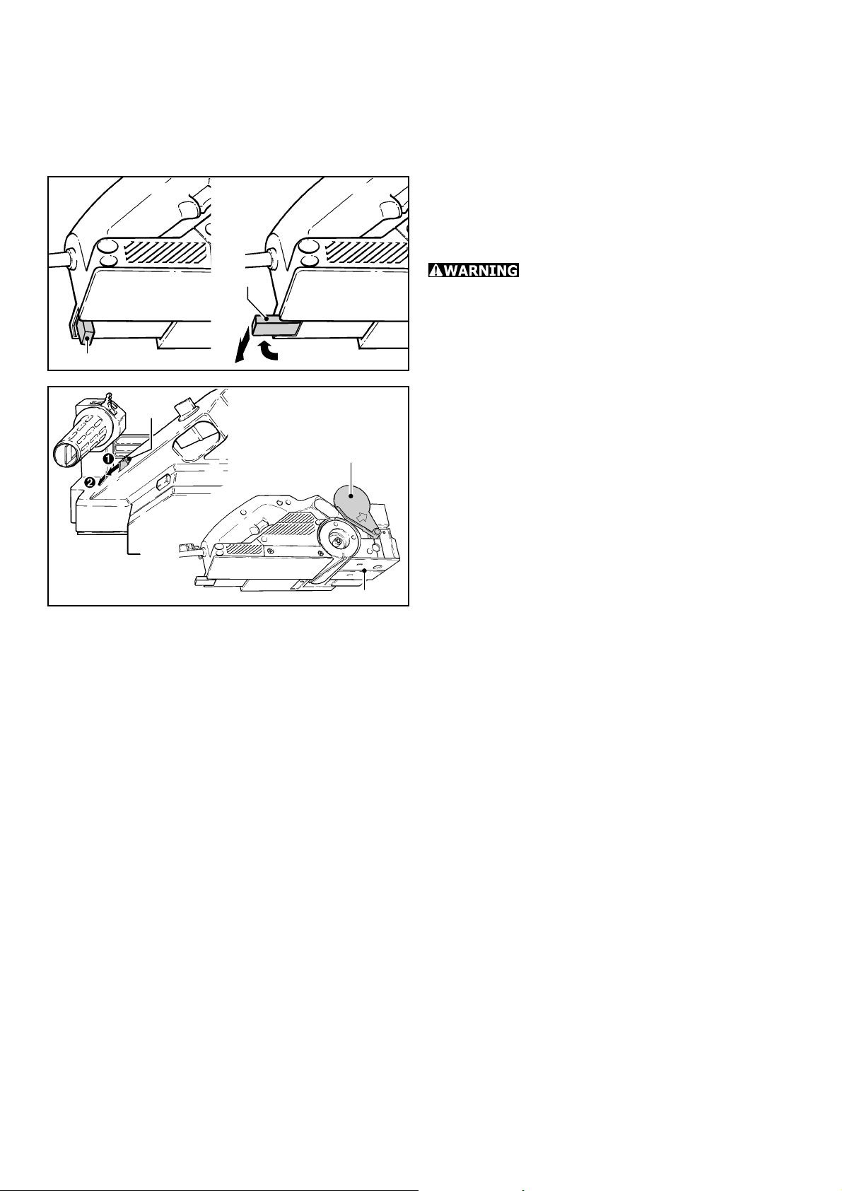
Dust extraction and
chip ejection
The planer is equipped as standard with a
connection for chip and dust extraction.
The shift lever (7.2) can be used to select
chip ejection (7.3) via the left- hand or righthand ejector aperture. Both these ejector
apertures allow the fi tting of either a chip
collection bag SB-HL or a Festool 36 mm dia.
suction hose.
The chip collection bag SB-HL is connected
by means of an adapter (7.5). The adapter
(included in the scope of delivery of the SBHL) is fi tted by inserting its lug (7.4) into the
lower edge of the chip ejector and is secured
by means of the screw (7.6) in the threaded
hole (7.1). The 36 mm dia. suction hose can
be fi tted either by clamping it directly into the
chip ejector aperture or by inserting it into the
adapter in the SB-HL.
If used with materials which produce hazardous dusts the electric tool should
be connected to a suitable extractor.
Working with the machine
The surface to be planed must
be free of metallic objects. Never plane over
screws, nails, etc.
When using the rustic planer
heads (HK 82 RF, HK 82 RG, HK 82 RW) work
with setting 0 mm since the rustic cutters
automatically project 1.5 mm beyond the
planer platen.
The planer is equipped with two handles to
enable it to be guided precisely. Place the front
platen onto the workpiece but do not allow
the planer head to come into contact with the
wood. Switch on the planer and bring it into
contact with the workpiece by pressing lightly
on the supplementary handle (1.7).
9
Page 10
8.1
o
8.2
The following basic rule applies for planing
wood: Optimum surface quality will be obtained by pressing on the front planer platen
when starting to plane and on the rear planer
platen (end of workpiece) when continuing or
fi nishing planing.
If the parking device should be found obstructive during special planing work it can
be swung back out of the way and locked in
position (8.2).
Always ensure, that when setting
the machine down on a surface the parking
device is correctly extended (8.1).
n
Rebating
9.1
9.2
9.3
The planer head is supported by a bearing on
one side only, thus allowing rebates of unlimited size to be cut with the planer. For this
purpose, the protective cover (9.2) must be
folded away. To do this, press the lever (9.1)
fi rst forwards and then to the left. This raises
the protective cover over the planer head to
the machine‘s housing, thus exposing the face
of the planer head.
At the end of work the protective cover automatically returns to its position over the
planer head.
Chamfering
The front planer platen is equipped with a
90° V groove (9.3) to allow the chamfering
of workpiece edges. This V groove is 2 mm
deep, thus producing a 2 mm edge chamfer
with the chip thickness setting 0 mm.
10
Bench-mounted operation
The planer can be operated bench-mounted in
conjunction with the bench-mounting device
SE-HL and the angle guide WA-HL. Detailed
instructions are supplied with each of these
accessories.
The angle guide can also be fi tted in place of
the parallel guide, supplied as standard with
the machine, and can be used for hand-guided
operation. The angle guide can be swivelled
to between 0° and 45°.
Page 11
10
11.1
Rustic planer heads
(accessories)
The planer can also be used to create rustic
surfaces. Three rustic planer heads are available for this purpose:
• HK 82 RG: creates a surface with a coarse structure.
• HK 82 RG: creates a surface with a fi ne struc-
ture.
• HK 82 RW: creates an uneven, wavy surface.
HK 82 RF
HK 82 RG
0.2
0
P
0 mm
HK 82 RW
11.3
11.2
The blades on the rustic planing head (HK 82
RF, HK 82 RG, HK 82 RW) protrude approx.
1.5 mm over the planer foot. When using
rustic planing heads on the planer, set the
cutting depth to 0 mm. Otherwise there is a
risk that the blades on the head will cut into
the planer foot and destroy the planer.
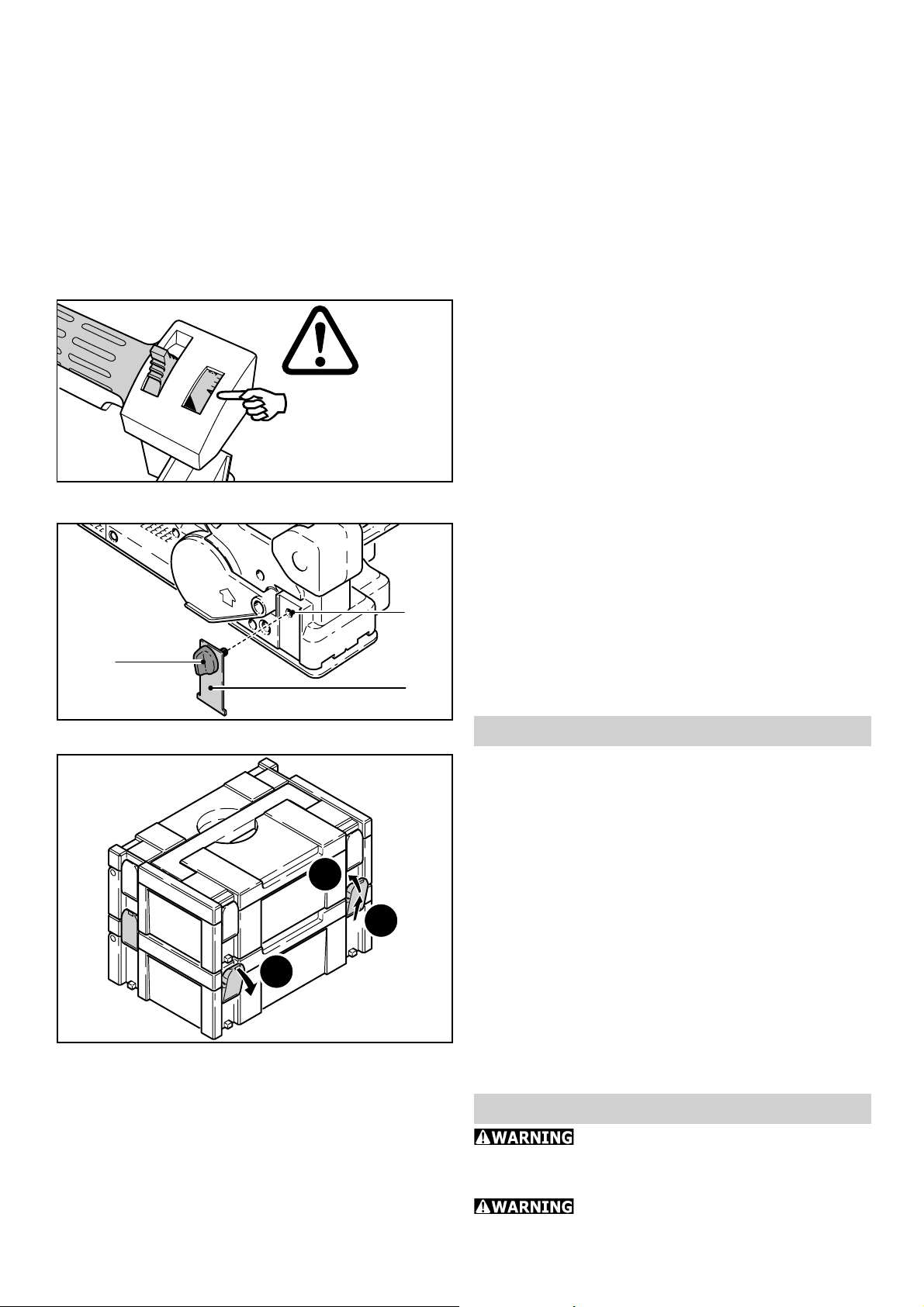
The cutting depth limiter (11.2) prevents the
cutting depth from increasing inadvertently
while planing work is performed.
Always attach the cutting depth limiter to the
planer before working with a rustic planing
head:
- Set the cutting depth on the planer to 0 mm,
- Attach the cutting depth limiter by inserting the
rotary knob (11.1) through the limiter and into
the threaded hole (11.3).
12.1
12.3
12.2
Systainer
Many Festool products are shipped in a
unique system container, called "Systainer".
This provides protection and storage for the
tool and accessories. The Systainers are
stackable and can be interlocked together.
They also can be interlocked atop Festool CT
dust extractors.
- Place one systainer on top of the other.
- Release all four latches on the lower systainer
by pulling back at their top edges (12.1).
- Slide all four latches upward (12.2).
- Snap all four latches back to their fl at position
(12.3) so they engage the stacking tabs of the
upper systainer.
Maintenance and service
Always disconnect the mains plug
from the socket before carrying out any maintenance work on the machine.
Any maintenance and repair work
requiring an opening of the motor housing
11
Page 12

may only be carried out by an authorised
customer service workshop.
The planer platen is made of a high-quality
magnesium alu minium alloy. Any corrosion
which may occur can be removed by buffi ng
using a fi ne elastic fi bre mat „V lies quality“
(grit S800). To prevent corrosion of the chromated planer head any cleansant used must
have a pH value of between 4.5 and 8.
Keep the ventilation slots in the motor housing
clean and free of obstructions at all times to
ensure an adequate circulation of air.
The planer is fi tted with special motor brushes
with an automatic cut-out. When the brushes
become worn the power supply is shut off
automatically and the planer comes to a
standstill.
Accessories, tools
For safety reasons, only use origi-
nal Festool accessories and tools!
Three rustic planer heads are also available
as accessories. The planer head HK 82 RG
provides a coarse rustic texture and the HK
82 RF a fi ne rustic texture. The planer head
HK 82 RW provides an irregular undulated
surface. All rustic planer heads can only be
fi tted with the HSS spiral cutters provided for
this purpose. No interchange is possible.
The accessory and tool order number can be
found in your Festool catalogue or on the Internet under www.festool-usa.com.
Warranty
Conditions of 1+2 Warranty
You are entitled to a free extended warranty
(1 year + 2 years = 3 years) for your Festool
power tool. Festool shall be responsible for
all shipping costs during the fi rst year of the
warranty. During the second and third year of
the warranty the customer is responsible for
shipping the tool to Festool. Festool will pay
for return shipping to the customer using UPS
Ground Service. All warranty service is valid
3 years from the date of purchase on your
receipt or invoice.
Festool Limited Warranty
This warranty is valid on the pre-condition that
the tool is used and operated in compliance
with the Festool operating instructions. Fes-
12
tool warrants, only to the original consumer
purchaser, that the specifi ed tool will be free
from defects in materials and workmanship
for a term of one year from the date of procurement. Festool makes no other warranty,
express or implied, for Festool portable power
tools. No agent, representative, distributor,
dealer or employee of Festool has the authority to increase or otherwise change the
obligations or limitations of this warranty. The
obligations of Festool in its sole discretion under this warranty shall be limited to the repair
or replacement of any Festool portable power
tool that is found to be defective as packaged
with the User Manual.
Excluded from coverage under this warranty
are: normal wear and tear; damages caused
by misuse, abuse or neglect; damage caused
by anything other than defects in material and
workmanship. This warranty does not apply to
accessory items such as circular saw blades,
drill bits, router bits, jigsaw blades, sanding
belts, and grinding wheels. Also excluded
are “wearing parts”, such as carbon brushes,
lamellas of air tools, rubber collars and seals,
sanding discs and pads, and batteries.
Festool portable power tools requiring replacement or repair are to be returned
with the receipt of purchase to Festool (call
800-554-8741 for address details).
IN NO EVENT SHALL FESTOOL BE LIABLE
FOR ANY CONSEQUENTIAL OR INCIDENTAL DAMAGES FOR BREACH OF THIS OR
ANY OTHER WARRANTY, EXPRESSED OR
IMPLIED WHATSOEVER. ALL WARRANTIES IMPLIED BY STATE LAW, INCLUDING THE IMPLIED WARRANTIES OF
MERCHANTABILITY AND FITNESS FOR
A PARTICULAR PURPOSE, ARE HEREBY
LIMITED TO THE DURATION OF THREE
YEARS.
Some states in the U.S. and some Canadian
provinces do not allow the limitations on how
long an implied warranty lasts, so the above
limitation may not apply to you. With the exception of any warranties implied by state or
province law as hereby limited, the foregoing
express limited warranty is exclusive and in
lieu of all other warranties, guarantees, agreements and similar obligations of Festool.
This warranty gives you specifi c legal rights
and you may also have other rights which vary
from state to state in the U.S. and province
to province in Canada.
Page 13

Table des matières
Régles de sécurité générales 13
Régles de sécurité pour rabot 15
Caractéristiques techniques 15
Symbole 15
Description fonctionnelle 16
Utilisation conforme 16
Raccordement électrique et mise en
service 16
Câble de rallonge 16
Réglage électronique 17
Réglages de la machine 17
Réglage de la prise de copeaux 18
Porte-outils et couteau hélicoïdal 18
Montage des butées 19
Aspiration et éjection de copeaux 19
Travailler avec la machine 20
Feuillurer 20
Chanfreiner 21
Utilisation en stationnaire 21
Porte-outils rustiques (accessoires) 21
Systainer 22
Entretien et maintenance 22
Accessoires, outils 22
Garantie 23
Régles de sécurité générales
Lire toutes les consi-
gnes de sécurité et indications. Le non-
respect des avertissements et instructions
indiqués ci-après peut entraîner un choc
électrique, un incendie et/ou de graves blessures.
Conserver tous les avertissements et
toutes les instructions pour pouvoir s’y
reporter ultérieurement.
Le terme « outil « dans les avertissements
fait reference à votre outil électrique alimenté
par le secteur (avec cordon d’alimentation)
ou votre outil fonctionnant sur batterie (sans
cordon d’alimentation).
1 PLACE DE TRAVAIL
a) Maintenez l’endroit de travail propre et
bien éclairé. Un lieu de travail en désordre ou
mal éclairé augmente le risque d’accidents.
b) N’utilisez pas l’appareil dans un envi-
ronnement présentant des risques d’ex-
plosion et où se trouvent des liquides,
des gaz ou poussières infl ammables. Les
outils électroportatifs génèrent des étincelles
risquant d’enfl ammer les poussières ou les
vapeurs.
c) Tenez les enfants et autres personnes
éloignés durant l’utilisation de l’outil
électroportatif. En cas d’inattention vous
risquez de perdre le contrôle sur l’appareil.
2 SECURITE RELATIVE AU SYSTEME
ELECTRIQUE
a) La fi che de secteur de l’outil électro-
portatif doit être appropriée à la prise
de courant. Ne modifi ez en aucun cas la
fi che. N’utilisez pas de fi ches d’adapta-
teur avec des appareils avec mise à la
terre. Les fi ches non modifi ées et les prises
de courant appropriées réduisent le risque de
choc électrique.
b) Evitez le contact physique avec des
surfaces mises à la terre tels que tuyaux,
radiateurs, fours et réfrigérateurs. Il y a
un risque élevé de choc électrique au cas où
votre corps serait relié à la terre.
c) N’exposez pas l’outil électroportatif
à la pluie ou à l’humidité. La pénétration
d’eau dans un outil électroportatif augmente
le risque d’un choc électrique.
d) N’utilisez pas le câble à d’autres fi ns
que celles prévues, n’utilisez pas le câble
pour porter l’appareil ou pour l’accrocher ou encore pour le débrancher de
la prise de courant. Maintenez le câble
éloigné des sources de chaleur, des parties grasses, des bords tranchants ou des
parties de l’appareil en rotation. Un câble
endommagé ou torsadé augmente le risque
d’un choc électrique.
e) Au cas où vous utiliseriez l’outil élec-
troportatif à l’extérieur, utilisez une
rallonge autorisée homologuée pour les
applications extérieures. L’utilisation d’une
rallonge électrique homologuée pour les applications extérieures réduit le risque d’un
choc électrique.
f) Si l’usage d’un outil dans un emplace-
ment humide est inévitable, utiliser une
alimentation protégée par un dispositif
à courant différentiel résiduel (RCD).
L’usage d’un RCD réduit le risque de choc
électrique.
13
Page 14

3 SECURITE DES PERSONNES
a) Restez vigilant, surveillez ce que vous
faites. Faites preuve de bon en utilisant
l’outil électroportatif. N’utilisez pas l’appareil lorsque vous êtes fatigué ou après
avoir consommé de l’alcool, des drogues ou avoir pris des médicaments. Un
moment d’inattention lors de l’utilisation de
l’appareil peut entraîner de graves blessures
sur les personnes.
b) Portez des équipements de protection.
Portez toujours des lunettes de protection. Le fait de porter des équipements de
protection personnels tels que masque antipoussières, chaussures de sécurité antidérapantes, casque de protection ou protection
acoustique suivant le travail à effectuer, réduit
le risque de blessures.
c) Evitez une mise en service par mégar-
de. Assurez-vous que l’interrupteur est
effectivement en position d’arrêt avant
de retirer la fi che de la prise de courant.
Le fait de porter l’appareil avec le doigt sur
l’interrupteur ou de brancher l’appareil sur la
source de courant lorsque l’interrupteur est
en position de fonctionnement, peut entraîner
des accidents.
d) Enlevez tout outil de réglage ou toute
clé avant de mettre l’appareil en fonctionnement. Une clé ou un outil se trouvant
sur une partie en rotation peut causer des
blessures.
e) Ne surestimez pas vos capacités.
Veillez à garder toujours une position
stable et équilibrée. Ceci vous permet de
mieux contrôler l’appareil dans des situations
inattendues.
f) Portez des vêtements appropriés. Ne
portez pas de vêtements amples, ni de
bijoux. Gardez les cheveux et les vêtements à distance des pièces mobiles. Des
vêtements amples, des bijoux ou des cheveux
longs peuvent être happés par les pièces en
mouvement.
g) Si des dispositifs servant à aspirer
ou à recueillir les poussières doivent
être utilisés, vérifi ez que ceux-ci soient
effectivement raccordés et qu’ils sont
correctement utilisés. L’utilisation de tels
dispositifs réduit les dangers dus aux poussières.
4 UTILISATION ET EMPLOI SOIGNEUX DE L’OUTIL ELECTROPORTATIF
a) Ne surchargez pas l’appareil. Utilisez
l’outil électroportatif approprié au travail à effectuer. Avec l’outil électroportatif
approprié, vous travaillerez mieux et avec
plus de sécurité à la vitesse pour laquelle il
est prévu.
b) N’utilisez pas un outil électroportatif
dont l’interrupteur est défectueux. Un
outil électroportatif qui ne peut plus être mis
en ou hors fonctionnement est dangereux et
doit être réparé.
c) Retirer la fi che de la prise de courant
avant d’effectuer des réglages sur l’appareil, de changer les accessoires, ou de
ranger l’appareil. Cette mesure de précau-
tion empêche une mise en fonctionnement
par mégarde.
d) Gardez les outils électroportatifs non
utilisés hors de portée des enfants. Ne
permettez pas l’utilisation de l’appareil
à des personnes qui ne se sont pas familiarisées avec celui-ci ou qui n’ont pas lu
ces instructions. Les outils électroportatifs
sont dangereux lorsqu’ils sont utilisés par des
personnes non initiées.
e) Prenez soin des outils électroportatifs.
Vérifi ez que les parties en mouvement
fonctionnent correctement et qu’elles ne
soient pas coincées, et contrôlez si des
parties sont cassées ou endommagées
de telle sorte que le bon fonctionnement
de l’appareil s’en trouve entravé. Faites
réparer les parties endommagées avant
d’utiliser l’appareil. De nombreux accidents
sont dus à des outils électroportatifs mal entretenus.
f) Maintenez les outils de coupe aiguisés
et propres. Des outils soigneusement entretenus avec des bords tranchants bien aiguisés
se coincent moins souvent et peuvent être
guidés plus facilement.
g) Utilisez les outils électroportatifs,
les accessoires, les outils à monter etc.
conformément à ces instructions et aux
prescriptions en vigueur pour ce type
d’appareil. Tenez compte également des
conditions de travail et du travail à effectuer. L’utilisation des outils électroportatifs à
14
Page 15

d’autres fi ns que celles prévues peut entraîner
des situations dangereuses.
5 SERVICE
a) Ne faites réparer votre outil électroportatif que par un personnel qualifi é et
seulement avec des pièces de rechange
d’origine. Ceci permet d’assurer la sécurité
de l’appareil.
Régles de sécurité pour rabot
Attendez l’immobilisation totale de la –
fraise avant de poser l’outil. Une fraise
exposée risque d’endommager la surface
sur laquelle elle est posée et d’entraîner
une perte du contrôle de l’outil ainsi que
de graves blessures.
Utilisez des serre-joints ou d’autres –
dispositifs pour bloquer et soutenir
la pièce sur une plate-forme stable.
Maintenir la pièce à la main ou contre son
corps n’est pas une solution stable, vous
risquez de perdre le contrôle de l’outil.
POUR RÉDUIRE LE RISQUE
DE DOMMAGES, L'UTILISATEUR DOIT LIRE
LE MANUEL D'INSTRUCTION.
Certaines poussières créées
par le ponçage mécanique, le sciage, le meulage, le perçage et autres activités reliées à
la construction contiennent des substances
chimiques connues (dans l’État de la Californie) comme pouvant causer le cancer,
des anomalies congénitales ou représenter
d’autres dangers pour la reproduction. Voici
quelques exemples de telles substances:
• plomb provenant de peintures à base de
plomb,
• silice cristallisée utilisée dans les briques, le
ciment et autres matériaux de maçonnerie, et
• arsenic et chrome du bois d’œuvre traité avec
un produit chimique.
Le risque d’exposition à de tels produits varie
selon la fréquence à laquelle vous faites ce
genre de travail.
Pour réduire les risques d’exposi-
tion à ces substances chimiques :
travaillez dans un endroit adéquatement ventilé et utilisez un
équipement de sécurité approuvé,
tel que masques antipoussières
spécialement conçus pour fi ltrer les
particules microscopiques.
Caractéristiques techniques
Puissance absorbée 850 W
Vitesse à vide 10 000 tr/min
Largeur de rabotage 82 mm (3.2 in.)
Prise de copeaux 0 - 3.5 mm (0 - 0.14 in.)
Profondeur de feuillure illimitée
Poids 3.9 kg (8.6 lbs)
Sécurité:
/ II selon
UL 745, CSA C22.2 No. 745
Symbole
Avertissement de danger
Lire les instructions / les remarques !
V Volt
A Ampère
Hz Hertz
W Watt
~ Tension alternative
n
Vitesse de rotation à vide
0
Classe II conception
tr/min tours par minute
15
Page 16

Description fonctionnelle
1.21.41.6 1.11.31.7 1.5
1.8
1.1 Blocage du interrupteur
1.2 Interrupteur marche/arrêt
1.3 Bouche d’ejection des copeaux
1.4 Levier commutateur pour l’ejection de
copeaux
1.5 Bloquez l’arbre du rabot
1.6 Blocage pour réglage de la profondeur
de coupe
1.7 Poignée supplémentaire / réglage de la
pro fondeur de coupe
1.8 Protège-pied
Utilisation conforme
Le rabot HL 850 E avec les outils de travail
de Festool est destines a traiter du bois, des
matières plastiques tendres et des matériaux
ressemblant au bois.
L‘utilisateur est tenu responsable de tous dommages et accidents
éventuels en cas d‘utilisation non conforme.
Raccordement électri-
que et mise en service
La tension du réseau doit correspondre à la
tension indiquée sur la plaque signalétique.
L‘interrupteur (1.2) sert de mise en marche/
arrêt de la machine. Pour votre sécurité, il est
équipé d‘un système de blocage de mise en
marche (1.1). Pour mettre le rabot en route, il
faut d‘abord appuyer sur le bouton du blocage
de mise en marche puis sur l‘interrupteur.
Câble de rallonge
Si une rallonge électrique est nécessaire,
elle doit présenter une section suffi sante afi n
d‘éviter une chute de tension excessive ou
une surchauffe. Une chute de tension excessive réduit la puissance et peut entraîner la
destruction du moteur. Le tableau ci-contre
indique le calibre des rallonges recommandées en fonction de longueur et de l‘intensité
nominale de l‘outil. Utilisez exclusivement
des rallonges recommandées par U.L. et CSA.
N‘utilisez jamais deux rallonges branchées
l‘une après l‘autre, mais remplacez-les par
une rallonge plus longue.
16
Page 17

Longueur totale
rallonge (pieds)
Section du câble
(AWG)
Remarque: plus le numéro A.W.G. est petit,
plus la section du câble est grande.
25 50 100 150
18 16 14 12
Réglage électronique
Les appareils sont équipés d‘une électronique
ayant les fonctions suivantes:
Démarrage progressif
Le démarrage progressif assure un démarrage
sans à-coups.
Vitesse à vide
L‘électronique limite la vitesse de rotation à
vide. Par conséquent, le niveau de bruit est
également minime en marche à vide.
Vitesse de rotation constante
La vitesse de rotation de l‘axe du rabot est
maintenue constante par un système électronique. Ceci assure une vitesse de coupe
constante même sous charge.
Sécurité contre les
surchauffes
Une grande utilisation en continu entraîne un
échauffement du moteur. Une sécurité électronique contre les surchauffes (brûlures du
moteur) est incluse dans la machine. Avant
d‘atteindre la température critique, ce dispositif électronique coupe le moteur. Après un
refroidissement de l‘ordre de 3 à 5 minutes, la
machine est de nouveau prête au fonctionnement. Le temps de refroidissement est réduit
en laissant tourner la machine à vide.
Ne travaillez pas avec le rabot si l‘électronique
est défectueuse. Cela peut entraîner une vitesse de rotation trop élevée. Une électronique
défectueuse peut être constatée en l‘absence
de démarrage progressif ou s‘il existe un bruit
sourd lors de la rotation à vide.
Réglages de la machine
Débranchez toujours la fi che
de la source de courant avant d‘entreprendre
quelque réglage que ce soit sur la machine ou
avant de monter/démonter un accessoire!
17
Page 18

2.3
+
-
2.2 2.1
0.8
0.6
0.4
0.2
Réglage de la pri-
se de copeaux
En impliquant une pression vers l‘arrière, on
effectue le déverrouillage (2.2) et en tournant
la poignée supplémentaire (2.3), on règle la
prise de copeaux progressivement entre 0 mm
et 3.5 mm. Le réglage est à lecture directe
sur la fenêtre graduée (2.1). Une graduation
correspond à une prise de 0.1 mm.
Si l‘on veut garder une prise de copeaux
constante, remettre le verrouillage en place
après avoir effectué le réglage. Si des réglages sont nécessaires au cours des travaux
(travaux d‘adaptation), laissez le verrouillage
ouvert.
En tournant la poignée supplémentaire audelà de 0 mm, on obtient la position P = position de repos. Le couteau hélicoïdal est ainsi
entièrement plongé dans le rabot. Ceci n‘est
pas le cas avec l‘utilisation des porte-outil à
effet rustique.
Pour cette raison, veillez à ce
que le protège-pied (1.8) situé au bout de la
semelle soit toujours correcte ment rabattu.
3.6
3.33.43.5 3.2
3.1
Porte-outils et cou-
teau hélicoïdal
Utilisez uniquement des fers
correctement affûtés et non endommagés. En
effet, des fers émoussés sont susceptibles de
provoquer des reculs de l’outil et de donner
lieu à un résultat de travail insatisfaisant.
Le rabot est équipé en série du porte-outil HK
82 SD. Le porte-outil possède un couteau en
biais. Tout réaffûtage est donc impossible.
a) Changement du porte-outil
Bloquez l‘arbre du rabot (3.5) et débloquez
la vis à six pans creux (3.1) sur le porte-outil
(3.4) avec la clé mâle normale d‘ouverture
(3.6). Retirez le porte-outil de l‘arbre.
Avant le montage du nouveau porte-outil,
vérifi ez l‘absence de poussières éventuelles
sur l‘arbre.
Le nouveau porte-outil est fi xé en procédant
dans le sens inverse, avec le fl asque de ser-
rage (3.3), la rondelle (3.2) et la vis à six pans
creux (3.6) sur l‘arbre.
18
Page 19

4.5
b) Changement du couteau hélicoïdal
4.2 4.3 4.44.1
Dévissez avec la clé mâle normale d‘ouverture
(4.1) se trouvant dans la poignée supplémentaire, les 3 vis de serrage (4.5) du porte-outil
jusqu‘à ce que le couteau puisse être retiré.
Avant de monter le nouveau couteau, il faut
nettoyer la rainure qui reçoit le couteau. Vous
avez ainsi la garantie que le couteau sera
parfaitement ajusté.
Poussez le nouveau couteau (4.4) avec l‘écriture visible dirigée vers la partie arrière de
la semelle du rabot dans la rainure du porte-outil, jusqu‘en butée. Avant de serrer les
vis, vérifi ez à l‘aide d‘une règle (4.2) que le
couteau hélicoïdal, en face avant, soit bien
en ligne avec la semelle avant et arrière du
rabot (4.3). Puis serrez d‘abord la vis centrale
et ensuite les deux vis extérieures.
Montage des butées
6.1
5.2
5.3
5.1
6.2
Le rabot est livré en standard avec une butée de profondeur de feuillure et un guide
parallèle.
a) Butée de profondeur de feuillure
La butée de profondeur de feuillure (5.1) doit
être fi xée dans le trou taraudé (5.2) du côté
droit avant de l‘appareil. Elle peut être réglée
progressivement entre 0 mm et 30 mm (graduation). La profondeur de feuillure réglée est
lisible dans le creux (5.3) du carter.
b) Guide parallèle
Le guide parallèle (6.2) doit être monté dans
le trou fi leté (6.1) à côté de la semelle ar-
rière.
Le guide angulaire basculant WA-HL (accessoire) peut également se monter à cet
endroit.
Aspiration et éjec-
tion de copeaux
7.1
7.2
7.3
7.6
7.5
7.4
Le rabot est équipé en série d‘un raccord
d‘aspiration des poussières et des copeaux.
Le côté d‘éjection des copeaux (7.3) peut
être sélectionné par l‘intermédiaire du levier
(7.2) et peut être au choix le côté gauche ou
le côté droit. On peut fi xer aux deux côtés
soit un sac récupérateur de copeaux SB-HL
soit un tuyau d‘aspiration Festool de 36 mm
de diamètre.
La fi xation du sac récupérateur de copeaux
SB-HL se fait par l‘intermédiaire d‘un adap-
19
Page 20

8.1
o
8.2
n
tateur (7.5). L‘adaptateur (fourni avec le SBHL) est accroché par sa patte (7.4) au bord
inférieur de l‘ouverture d‘éjection des copeaux
et fi xé avec la vis (7.6) dans le trou taraudé
(7.1). Le tuyau d‘aspiration de 36 mm de
diamètre peut être monté soit directement
dans l‘ouverture d‘éjection des copeaux soit
être fi xé à l‘adaptateur du SB-HL.
En cas de traitement de
matériaux produi sant des poussières nocives
pour la santé, cet outil électrique doit être raccordé à un dispositif d‘aspiration approprié.
Travailler avec la machine
La partie à usiner ne doit
comporter aucune partie métallique. Ne pas
raboter dans des vis, clous, etc.
En utilisant le porte-outil
à effet rustique (HK 82 RF, HK 82 RG,
HK 82 RW), l‘usinage se fait en position 0 mm
car les couteaux dépassent automatiquement
la semelle de 1.5 mm.
Pour tenir parfaitement le rabot, il est équipé
de deux poignées. Posez le rabot sur le matériau avec la semelle avant, en veillant à ce
que le porte-outil ne touche pas encore le
bois. Activez le rabot et glissez-le sur le matériau en donnant une légère pression sur la
poignée (1.7).
Une règle de base pour le rabotage: La
meilleure qualité de rabotage est obtenue en
appuyant, au démarrage du rabotage, sur
la partie avant de la semelle du rabot et; en
arrivant à la fi nition (extrémité de la pièce à
usiner) sur la partie arrière de la semelle.
Si, pour des travaux spécifi ques, le protège-
pied devait gêner, il peut être rabattu vers
l‘arrière et bloqué (8.2).
Veillez à ce que le protège-pied soit toujours correcte ment rabattu
(8.1).
20
9.1
9.2
Feuillurer
Le rabot est équipé d‘un porte-outil qui est
logé unilatéralement, ce qui permet de réaliser des feuillures à profondeur sans limites.
Pour ce faire, il faut escamoter le carter (9.2).
Pour y parvenir, poussez le levier (9.1) vers
l‘avant puis vers la gauche. Le capot se lève
jusqu‘en butée et la partie frontale du porteoutil est libérée.
9.3
Page 21

Après usinage, le capot se met automatiquement dans sa position initiale.
Chanfreiner
Pour réaliser un chanfrein sur une arête, la
semelle avant du rabot est équipée d‘une
rainure en V de 90° (9.3). Cette rainure a
une profondeur de 2 mm. Ainsi, en prise de
copeaux réglée à 0 mm, l‘arête est rabotée
de 2 mm.
Utilisation en stationnaire
En utilisant le dispositif stationnaire SE-HL et la
butée angulaire WA-HL, vous pouvez utiliser le
rabot en stationnaire. Une description détaillée
d‘utilisation fi gure dans l‘emballage des deux
accessoires. La butée angulaire peut également être utilisée au lieu de la butée parallèle
qui est un accessoire standard, pour travailler
en avance manuelle avec le rabot. La butée
angulaire peut être inclinée de 0° à 45°.
10
11.1
Porte-outils rustiques
(accessoires)
Ce rabot permet de créer des surfaces d‘aspect rustique. Trois porte-outils rustiques sont
disponibles à cet effet.
HK 82 RF
HK 82 RG
0.2
0
P
0 mm
HK 82 RW
11.3
11.2
• HK 82 RG : pour une structuration grossière de
la surface.
• HK 82 RF : pour une structuration fi ne de la
surface.
• HK 82 RW : pour une structuration ondulée de
la surface.
Les couteaux des porte-outils Rustikal (HK
82 RF, HK 82 RG, HK 82 RW) dépassent
d‘environ 1,5 mm de la semelle du rabot. Par
conséquent, lors du montage des porte-outils
Rustikal sur le rabot, il faut régler la profondeur de travail sur 0 mm. Sinon, les couteaux
des porte-outils Rustikal risquent de mordre
dans la semelle du rabot et d‘endommager
ce dernier.
Le dispositif de limitation de la profondeur
de travail (11.2) empêche tout dépassement
involontaire de la profondeur de travail lors
du travail avec le rabot.
Toujours fi xer le dispositif de limitation de la
profondeur de travail au rabot avant de travailler avec un porte-outils Rustikal :
- Régler la profondeur de travail du rabot sur
0 mm,
- Fixer le dispositif de limitation de la profondeur
de travail avec la molette (11.1) au niveau de
l‘alésage taraudé (11.3).
21
Page 22

12.1
12.3
12.2
Systainer
De nombreux produits Festool sont fournis
dans une caisse exclusive, appelée "Systainer". Celle-ci permet de protéger et de ranger
des outils et des appareils complémentaires.
Les Systainer sont empilables et peuvent
être solidarisés. En outre, il se fi xent sur les
aspirateurs CT Festool.
- Poser deux Systainer l'un sur l'autre,
- défaire les quatre éléments de verrouillage
du Systainer inférieur en les tirant en arrière
par leur bord supérieur (12.1).
- pousser les quatre éléments de verrouillage
vers le haut (12.2)
- manoeuvrer les quatre éléments de verrouillage (12.3) de sorte qu'ils s'enclenchent
au niveau des éléments récepteurs du Systainer supérieur.
Entretien et maintenance
Avant tous travaux d‘entre-
tien sur la machine, débranchez l‘appareil.
Tous travaux d‘entretien et
de réparation nécessitant l‘ouverture du carter
moteur ne doivent être effectués que par un
service après-vente Festool.
La semelle du rabot est en alliage de haute
qualité de magnésium et d‘aluminium. Les
éventuelles apparitions de corrosion peuvent
être éliminées avec la texture abrasive (grain
S800). Pour éviter des traces de corrosion sur
le porte-outil chromé, il faut utiliser un produit de nettoyage ayant une valeur pH située
entre 4.5 et 8.
Pour assurer une bonne circulation d‘air, les
ouvertures d‘aération dans le carter du moteur doivent toujours être maintenues ouvertes et propres.
Le rabot est équipé de charbons spécifi ques
à coupure automatique en cas d‘usure. Cette
coupure de courant automatique entraîne
l‘arrêt du fonctionnement de la machine.
22
Accessoires, outils
Pour des raisons de sécurité,
il faut utiliser exclusivement des accessoires
et outils d‘origine Festool!
Dans le programme, nous proposons également comme accessoires, trois porte-outils à
effet rustique. Avec le porte-outil HK 82 RG,
on obtient un effet rustique gros et avec le
Page 23

HK 82 RF, un effet rustique fi n. Quant au HK
82 RW, la surface est irrégulièrement ondulée. Tous les porte-outils à effet rustique ne
peuvent être équipés qu‘avec des couteaux
HSS prévus à cet effet. Ils ne peuvent pas
être interchangés.
Les références des accessoires et outils fi gu-
rent dans le catalogue Festool ou sur Internet
sous www.festool-usa.com.
Garantie
Conditions de la ga-
rantie (1+2 ans)
Vous avez droit à une prolongation de garantie
gratuite (1 an + 2 ans = 3 ans) sur votre outil
électrique Festool. Festool assumera tous les
coûts d’expédition pendant la première année
de la garantie alors que les deuxième et troisième années, les coûts devront être assumés
par le client. Festool paiera les frais de retour
de l’outil au client par service de livraison terrestre UPS. La garantie est valable pour une
période de 3 ans à compter de la date d’achat
indiquée sur votre reçu ou votre facture.
Garantie limitée de Festool
Cette garantie est valable à condition que
l’outil soit utilisé conformément aux instructions de Festool. Festool garantit, à l’acheteur
initial seulement, que l’outil indiqué sera
exempt de tout défaut de matériau et de fabrication pendant un an à compter de la date
d’achat. Festool ne donne aucune garantie
supplémentaire, implicite ou explicite, sur
les instruments portables électriques Festool. Aucun agent, représentant commercial,
distributeur, vendeur ou employé de Festool
n’est autorisé à prolonger ou à modifi er les
obligations ou restrictions de la présente garantie. Les obligations de Festool sont, à son
entière discrétion, limitées à la réparation ou
à l’échange des outils portables électriques
Festool trouvés défectueux dans le présent
emballage, tels que fournis avec le présent
Guide d’utilisation.
Cette garantie exclut l’usure normale, les
dommages causés par un usage impropre,
les abus ou la négligence, ou tout dommage
autre que ceux attribuables à des défauts de
matériau et de fabrication. Cette garantie ne
s’applique pas aux accessoires tels que lames
de scie circulaire, mèches de perceuse et vilebrequin, lames de scie sauteuse, bandes abrasives et meules. Sont également exclues les
pièces d’usure, telles que balais de charbon,
lamelles pour outils à air comprimé, joints et
manchons de caoutchouc, disques et patins
ponceurs, ainsi que les piles.
Les outils électriques portables Festool à
remplacer ou à réparer doivent être retournés avec le reçu d’achat à Festool (appelez
au 800-554-8741 pour connaître l’adresse
d’expédition).
FESTOOL N’EST EN AUCUN CAS RESPONSABLE DES DOMMAGES DIRECTS
OU INDIRECTS, IMPLICITES OU EXPLICITES, DÉCOULANT DE LA RUPTURE DE
CETTE GARANTIE OU DE TOUTE AUTRE
GARANTIE. TOUTES LES GARANTIES IMPLICITES, Y COMPRIS LES GARANTIES
IMPLICITES DE QUALITÉ MARCHANDE
ET D’ADÉQUATION À UN USAGE PARTICULIER, SONT LIMITÉES À UNE PÉRIODE
DE TROIS ANS.
Certains états américains et certaines provinces canadiennes ne permettent pas la limitation des garanties implicites; il se pourrait
donc que les limites indiquées ci-dessus ne
s’appliquent pas dans votre cas. À l’exception
de certaines garanties implicites des provinces ou des états indiquées ici, la présente
garantie est exclusive et remplace toute autre
garantie, convention et obligation similaire
de Festool.
Cette garantie vous confère des droits légaux
spécifi ques, et vous pouvez aussi avoir d’autres
droits pouvant varier d’un état à l’autre, ou
d’une province à l’autre au Canada.
23
Page 24

Contenido
Normas generales de seguridad 24
Reglas de seguridad para cepillos 25
Datos técnicos 26
Símbolos 26
Descripción del funcionamiento 26
Uso conforme a la destinación 27
Conexión eléctrica y puesta en
servicio 27
Cable de prolongación 27
Regulación electrónica 27
Ajustes en la máquina 28
Ajuste del espesor de la viruta 29
Cabezas de cepillo y cuchilla helicoidal 29
Montaje de los topes 30
Aspiración y expulsión de virutas 30
Trabajo con la máquina 31
Rebajar 32
Biselar 32
Aplicación en instalación fi ja 32
Cabezal de cepillo rústico (accesorio) 32
Systainer 33
Mantenimiento y conservación 33
Accesorios, herramientas 34
Garantiá 34
Normas genera-
les de seguridad
Lea íntegramente las ins-
trucciones e indicaciones de seguridad.
El incumplimiento de dichas instrucciones
e indicaciones puede dar lugar a descargas
eléctricas, incendios o lesiones graves.
Guardar todas las advertencias de peligro
e instrucciones para futuras consultas.
El término herramienta eléctrica empleado
en las siguientes advertencias de peligro se
refi ere a herramientas eléctricas de conexión
a la red (con cable de red) y a herramientas
eléctricas accionadas por acumulador (o sea,
sin cable de red).
1 PUESTO DE TRABAJO
a) Mantenga limpio y bien iluminado su
puesto de trabajo. El desorden y una ilu-
minación defi ciente en las áreas de trabajo
pueden provocar accidentes.
b) No utilice la herramienta eléctrica en
un entorno con peligro de explosión,
en el que se encuentren combustibles
líquidos, gases o material en polvo. Las
herramientas eléctricas producen chispas que
pueden llegar a infl amar los materiales en
polvo o vapores.
c) Mantenga alejados a los niños y otras
personas de su puesto de trabajo al
emplear la herramienta eléctrica. Una
distracción le puede hacer perder el control
sobre el aparato.
2 SEGURIDAD ELÉCTRICA
a) El enchufe del aparato debe corres-
ponder a la toma de corriente utilizada.
No es admisible modifi car el enchufe en
forma alguna. No emplear adaptadores
en aparatos dotados con una toma de
tierra. Los enchufes sin modifi car adecuados
a las respectivas tomas de corriente reducen
el riesgo de una descarga eléctrica.
b) Evite que su cuerpo toque partes co-
nectadas a tierra como tuberías, radiadores, cocinas y refrigeradores. El riesgo
a quedar expuesto a una sacudida eléctrica
es mayor si su cuerpo tiene contacto con
tierra.
c) No exponga las herramientas eléctricas
a la lluvia y evite que penetren líquidos
en su interior. Existe el peligro de recibir una
descarga eléctrica si penetran ciertos líquidos
en la herramienta eléctrica.
d) No utilice el cable de red para trans-
portar o colgar el aparato, ni tire de él
para sacar el enchufe de la toma de corriente. Mantenga el cable de red alejado
del calor, aceite, esquinas cortantes o
piezas móviles. Los cables de red dañados
o enredados pueden provocar una descarga
eléctrica.
e) Al trabajar con la herramienta eléc-
trica en la intemperie utilice solamente
cables de prolongación homologados
para su uso en exteriores. La utilización
de un cable de prolongación adecuado para
su uso en exteriores reduce el riesgo de una
descarga eléctrica.
f) Si fuese imprescindible utilizar la he-
rramienta eléctrica en un entorno húmedo, es necesario conectarla a través de
un fusible diferencial. La aplicación de un
fusible diferencial reduce el riesgo a exponerse a una descarga eléctrica.
3 SEGURIDAD DE PERSONAS
a) Esté atento a lo que hace y emplee
la herramienta eléctrica con prudencia.
24
Page 25

No utilice la herramienta eléctrica si
estuviese cansado, ni tampoco después
de haber consumido alcohol, drogas o
medicamentos. El no estar atento durante
el uso de una herramienta eléctrica puede
provocarle serias lesiones.
b) Utilice un equipo de protección y en
todo caso unas gafas de protección. El
riesgo a lesionarse se reduce considerablemente si, dependiendo del tipo y la aplicación de la herramienta eléctrica empleada,
se utiliza un equipo de protección adecuado
como una mascarilla antipolvo, zapatos de
seguridad con suela antideslizante, casco, o
protectores auditivos.
c) Evite una puesta en marcha fortuita del
aparato. Cerciorarse de que el aparato
esté desconectado antes conectarlo a la
toma de corriente. Si transporta el aparato
sujetándolo por el interruptor de conexión/
desconexión, o si introduce el enchufe en la
toma de corriente con el aparato conectado,
ello puede dar lugar a un accidente.
d) Retire las herramientas de ajuste o
llaves fi jas antes de conectar la herra-
mienta eléctrica. Una herramienta o llave
colocada en una pieza rotante puede producir
lesiones al ponerse a funcionar.
e) Sea precavido. Trabaje sobre una base
fi rme y mantenga el equilibrio en todo
momento. Ello le permitirá controlar mejor la
herramienta eléctrica en caso de presentarse
una situación inesperada.
f) Utilice ropa adecuada. No utilice ropa
ancha ni objetos de joyería o bisutería.
Mantenga el pelo y la ropa alejada de
las piezas en movimiento. La ropa suelta
o el pelo largo pueden quedar atrapados por
piezas en movimiento.
g) Siempre que sea posible utilizar unos
equipos de aspiración o captación de polvo, asegúrese que éstos estén montados
y que sean utilizados correctamente. El
empleo de estos equipos reduce los riesgos
derivados del polvo.
4 TRATO Y USO CUIDADOSO DE HERRAMIENTAS ELÉCTRICAS
a) No sobrecargue el aparato. Use la
herramienta prevista para el trabajo a
realizar. Con la herramienta adecuada po-
drá trabajar mejor y más seguro dentro del
margen de potencia indicado.
b) No utilice herramientas con un inte-
rruptor defectuoso. Las herramientas que
no se puedan conectar o desconectar son
peligrosas y deben hacerse reparar.
c) Saque el enchufe de la red antes de
realizar un ajuste en el aparato, cambiar
de accesorio o al guardar el aparato. Esta
medida preventiva reduce el riesgo a conectar
accidentalmente el aparato.
d) Guarde las herramientas fuera del al-
cance de los niños y de las personas que
no estén familiarizadas con su uso. Las
herramientas utilizadas por personas inexpertas son peligrosas.
e) Cuide sus aparatos con esmero. Con-
trole si funcionan correctamente, sin
atascarse, las partes móviles del aparato,
y si existen partes rotas o deterioradas
que pudieran afectar al funcionamiento
de la herramienta. Si la herramienta eléctrica estuviese defectuosa haga repararla
antes de volver a utilizarla. Muchos de los
accidentes se deben a aparatos con un mantenimiento defi ciente.
f) Mantenga los útiles limpios y afi lados.
Los útiles mantenidos correctamente se dejan
guiar y controlar mejor.
g) Utilice herramientas eléctricas, ac-
cesorios, útiles, etc. de acuerdo a estas
instrucciones y en la manera indicada
específi camente para este aparato. Con-
sidere en ello las condiciones de trabajo
y la tarea a realizar. El uso de herramientas
eléctricas para trabajos diferentes de aquellos para los que han sido concebidas puede
resultar peligroso.
5 SERVICIO
a) Únicamente haga reparar su herra-
mienta eléctrica por un profesional,
empleando exclusivamente piezas de repuesto originales. Solamente así se mantie-
ne la seguridad de la herramienta eléctrica.
Reglas de seguridad
para cepillos
Espere a que el cortador se haya –
detenido antes de bajar la herramienta.
Un cortador al descubierto puede entrar
en contacto con la superfi cie y provocar
una pérdida de control con las lesiones
consiguientes.
25
Page 26

Utilice bridas u otro método similar –
para asegurar y sujetar la pieza de
trabajo sobre una plataforma estable.
Si sujeta la pieza con la mano o la apoya
contra el cuerpo, la pérdida de equilibrio
puede hacerle perder el control.
PARA REDUCIR EL RIESGO DE
LESIÓN, EL USUARIO DEBE LEER EL MANUAL
DE INSTRUCCIÓN.
Algunos polvos creados por
lijadoras motorizadas, aserraderos, trituradores, perforadoras y otras actividades de construcción contienen sustancias químicas que
se sabe (en el Estado de California) causan
cáncer, defectos de nacimiento u otros daños
al sistema reproductivo. Algunos ejemplos de
estas sustancias químicas son:
• Plomo de las pinturas con base de plomo
• Sílice cristalino de los ladrillos y cemento y otros
productos de mampostería, y
• Arsénico y cromo de madera tratada con sus-
tancias químicas
El riesgo de exposición a estas sustancias
varía, dependiendo de cuantas veces se hace
este tipo de trabajo.
Para reducir el contacto con estas
sustancias químicas: trabaje en un
área con buena ventilación y trabaje con equipo de seguridad aprobado, como mascarillas para el polvo
diseñadas espe cí fi camente para
fi ltrar partículas microscópicas.
Datos técnicos
Potencia absorbida 850 W
Velocidad sin carga 10 000 r.p.m.
Anchura de cepillo 82 mm (3.2 in.)
Extracción de viruta 0 - 3.5 mm (0 - 0.14
in.)
Profundidad de rebaje limitada
Peso 3.9 kg (8.6 lbs)
Seguridad:
/ II según
UL 745, CSA C22.2 No. 745
Símbolos
Aviso ante un peligro general
¡Leer las instrucciones e indicaciones!
V voltios
A amperios
Hz hertzios
W vatios
~ rensión alterna
n
revoluciones sin carga
0
Clase II Construcción
r.p.m. revoluciones por minuto
26
Descripción del fun-
cionamiento
1.21.41.6 1.11.31.7 1.5
1.8
1.1 Bloqueo de interruptor
1.2 Interruptor de conexión/desconexión
1.3 Expulsión de virutas
1.4 Palanca de cambio para expulsión de
virutas
1.5 Bloqueo del husillo
1.6 Bloque del ajuste del espesor de la
viruta
1.7 Mango adicional / ajuste del espesor
de la viruta
1.8 Zapata de reposo
Page 27

Uso conforme a la
destinación
El cepillo HL 850 E está apropiado para elaborar madera, plásticos blandos y materiales
parecidos a la madera con las herramientas
que ofrece Festool.
En caso de daños y accidentes
debidos a una utilización inadecuada o incorrecta la responsabilidad será del usuario.
Conexión eléctrica y
puesta en servicio
La tensión de la red tiene que coincidir con
la tensión indicada en la placa de características.
El interruptor (1.2) sirve para conectar/ desconectar. Para su seguridad está provisto con
un bloqueo de interruptor (1.1). Para poner
en funcionamiento el cepillo hay que accionar
primero el bloqueo de conexión y luego el
pulsador de puesta en marcha.
Cable de prolongación
Cuando se necesite un cable de prolongación,
éste tiene que disponer de una sección sufi -
ciente a fi n de evitar una excesiva caída de
tensión o un sobrecalentamiento. Una excesiva caída de la tensión reduce la potencia y
puede conducir a una destrucción del motor.
La tabla muestra el tamaño correcto a utilizar,
según la longitud del cordón y la capacidad
nominal en amperios de la herramenta. Emplear únicamente los cables de prolongación
listados por U.L. y CSA. No emplear nunca dos
cables de prolongación conectados el uno con
el otro. En lugar de ello, emplear uno correspondientemente largo.
Longitud total del cable
(pies)
Diámetro de cable
(AWG)
Observación: Cuanto más bajo es el número A.W.G., tanto mayor es el diámetro del
cable.
25 50 100 150
18 16 14 12
Regulación electrónica
Los aparatos tienen una cabeza electrónica
con las siguientes funciones:
27
Page 28

Arranque suave
El arranque suave regulado electrónicamente
vela por un arranque sin sacudidas del motor.
Número de revolucio-
nes en marcha en vacío
El sistema electrónico limita el número de revoluciones. De esta forma el índice de ruidos
permanece bajo también durante la marcha
en vacío.
Número de revolu-
ciones constante
El número de revoluciones del eje del cepillo
se mantiene electrónicamente constante. Así
también se consigue bajo carga una velocidad
de corte constante.
Seguro contra aumen-
to de temperatura
En caso de aplicación continua con una gran
sobrecarga, el motor se recalienta. Para protegerlo contra calentamiento (quemado del
motor), tiene integrado un control electrónico de temperatura. Antes de alcanzar una
temperatura peligrosa para el motor, éste se
desconecta por medio de la electrónica de
seguridad. Después de una refrigeración de
aprox. 3-5 minutos, la máquina está dispuesta
nuevamente para el funcionamiento y para ser
utilizada a pleno rendimiento. Con la máquina
en marcha (marcha sin carga), el tiempo de
refrigeración se reduce enormemente.
No utilizar el HL 850 E cuando la electrónica
sea defectuosa, dado que esto podría dar lugar a una velocidad de giro ex cesiva. Los fallos
de la electrónica se manifi estan por la pérdida
de la suavidad de arranque, por el aumento
del ruido en vacio o por la imposibilidad de
regular la velocidad de giro.
28
Ajustes en la máquina
¡Antes de todo trabajo en la
máquina se tiene que desenchufar el enchufe
de red de la toma de corriente!
Page 29

Ajuste del espe-
sor de la viruta
2.3
+
-
2.2 2.1
0.8
0.6
0.4
0.2
Después de quitar el bloqueo (2.2) pulsando
hacia atrás, se puede ajustar el espesor de
la viruta girando el mango adicional (2.3) sin
escalonamiento entre 0 mm y 3.5 mm. El
espesor de la viruta ajustado puede verse en
la mirilla de la escala (2.1). Una marca parcial
signifi ca 0.1 mm de extracción de viruta.
Si se quiere fi jar un espesor de viruta, se debe
pulsar nuevamente hacia adelante el bloqueo
del ajuste de espesor de virutas. Si durante
el trabajo se debe modifi car el espesor (tra-
bajos de adaptación), el bloqueo permanece
abierto.
Girando el mango adicional más allá de la
marca 0 mm se llega a la posición P = Posición de estacionamiento, en la cual la cuchilla
helicoidal está completamente hundida en el
cepillo. Sin embargo esto no es válido cuando
se emplean cabezas de cepillo-Rústico.
Asegúrese siempre que desconecte el aparato de que el zapata de reposo
(1.8) al fi nal de la base del cepillo esté abatido
correspondientemente.
3.6
3.33.43.5 3.2
3.1
Cabezas de cepillo y cu-
chilla helicoidal
Utilice sólo cuchillas afi ladas y
en buen estado. Las cuchillas romas aumentan el riesgo de que el cepillo salte hacia atrás
y empeoran la calidad del trabajo.
El cepillo está equipado de serie con el cabezal de cepillo HK 82 SD. El cabezal de cepillo
tiene fi los inclinados, de modo que la cuchilla
no pueda reafi larse.
a) Cambio de la cabeza del cepillo
Frene con el bloqueo del husillo (3.5) el eje del
cepillo y afl oje con la llave macho hexagonal
de tamaño (3.1) el tornillo de hexágono interior (3.6) en la cabeza del cepillo (3.4). Quite
la cabeza del cepillo del eje del cepillo.
Antes de colocar la cabeza de cepillo, debería
limpiar el eje del cepillo de posibles residuos
de polvo.
Ajustar la cabeza de cepillo nueva en orden inverso, con la brida de sujeción (3.3), arandela
(3.2) y tornillo de hexágono interior (3.6), al
eje del cepillo.
29
Page 30

4.5
b) Cambio de la cuchilla helicoidal
4.2 4.3 4.44.1
Afl oje con la llave de espiga hexagonal tama-
ño (4.1) alojada en el mango adicional, los
tres tornillos de sujeción (4.5) de la cabeza
del cepillo hasta que pueda extraer la cuchilla
helicoidal.
Antes de montar la nueva cuchilla se tiene que
limpiar la ranura de alojamiento de la cuchilla.
Con esto se asegura que la cuchilla quede
automáticamente bien ajustada después de
haber sido colocada.
Empuje la nueva cuchilla helicoidal (4.4), con
la parte rotulada hacia la superfi cie inferior
trasera del cepillo, en la ranura de alojamiento. Antes de que vuelva a afi anzar el tornillo
tensor, tiene que ajustar la cuchilla helicoidal
mediante la ayuda de una regla (4.2), de tal
manera que esté frontal en una línea con la
superfi cie inferior trasera y delantera del ce-
pillo (4.3). Afi ance entonces en primer lugar
el tornillo tensor central y después ambos
exteriores.
5.2
5.3
5.1
Montaje de los topes
La dotación de suministro del cepillo contiene
un tope para graduar la profundidad de rebaje
y un tope paralelo.
a) Tope para graduar la profundidad de
rebaje
El tope para graduar la profundidad de rebaje
(5.1) se ajusta con la rosca (5.2) en la parte
delantera derecha del aparato. Se puede graduar sin escalonamiento según escala entre
0 mm y 30 mm. La profundidad de rebaje
ajustada puede leerse en la muesca (5.3) del
cuerpo del aparato.
b) Tope paralelo
El tope paralelo (6.2) se ajusta con la rosca
(6.1) junto a la base posterior del cepillo.
En la misma posición se puede montar el tope
angular orientable WA-HL, el cual se puede
suministrar como accesorio.
30
6.1
6.2
Aspiración y expul-
sión de virutas
El cepillo está equipado de serie con un empalme para la aspiración de polvo y virutas. La
expulsión de las virutas (7.3) puede realizarse
Page 31

7.1
7.2
7.3
7.6
7.5
7.4
por medio de la palanca reversible (7.2), tanto por la rendija de expulsión de la derecha,
como por la de la izquierda, según se prefi era.
En ambas rendijas puede colocarse una bolsa
de recogida de virutas SB-HL o bien un tubo
de aspiración Festool de 36 mm Ø.
La fi jación de la bolsa de recogida de viru-
tas SB-HL se realiza mediante un adaptador
(7.5). El adaptador (en la dotación de suministro SB-HL) se engancha con la oreja (7.4)
al canto inferior de la expulsión de virutas y
se fi ja con el tornillo (7.6) en la rosca (7.1). El
tubo de aspi ración de 36 mm Ø puede ponerse
directamente en la rendija de expulsión de
virutas o bien en el adaptador de la SB-HL.
Si se usa el aparato prolongadamente para ela borar materiales perjudiciales para la salud, el aparato eléctri co deberá
conectarse a un dispositivo de aspiración
adecuado.
8.2
Trabajo con la máquina
La superfi cie a cepillar tiene
que estar libre de partículas metálicas. Nunca
cepille sobre tornillos, clavos, etc.
Al emplear las cabezas de cepillos-Rústico (HK 82 RF, HK 82 RG, HK 82 RW)
trabaje en la posición 0 mm, ya que las cuchillas Rústico sobresalen automáticamente
1.5 mm de la base del cepillo.
Para lograr un guiado exacto del cepillo, éste
está equipado con dos puños. Coloque el
cepillo con la base delantera sobre la pieza a
trabajar, sin que la cabeza del cepillo toque la
madera. Conecte el cepillo y desplácelo sobre
la pieza a trabajar con una presión leve sobre
el puño adicional (1.7).
Como regla básica al cepillar sirve que: La mayor calidad de superfi cie se consigue cuando,
al comenzar el cepillado, se presiona sobre
la superfi cie inferior delantera, y durante el
cepillado sobre la superfi cie trasera (parte
fi nal) del cepillo.
Si en casos especiales de aplicación molestase el zapata de reposo en el cepillado, éste
se puede plegar hacia atrás y así retenerlo
(8.2).
Asegúrese siempre que desconecte el aparato de que el zapata de reposo
esté abatido correspondientemente (8.1).
8.1
o
n
31
Page 32

Rebajar
9.1
9.2
9.3
El cepillo tiene una cabeza de cepillo situada
lateralmente. Por esta razón se puede lograr
un rebaje ilimitado. Para ello hay que quitar
la caperuza protectora (9.2). Esto se logra
presionando la palanca (9.1) primero hacia
adelante y luego hacia atrás. De esta forma
se desplaza la caperuza protectora por encima
de la cabeza del cepillo hasta el cuerpo del
aparato, quedando así libre la parte frontal de
la cabeza del cepillo.
Después de fi nalizar el trabajo, la caperuza
protectora cubre de inmediato automáticamente la cabeza del cepillo.
Biselar
Para biselar cantos de piezas de trabajo, la
base delantera del cepillo está equipada con
una ranura en V de 90° (9.3). Esta ranura en V
tiene una profundidad de 2 mm, de tal manera
que con graduación del espesor de virutas en
0 mm, los cantos se biselan en 2 mm.
10
Aplicación en instalación fi ja
En relación con la instalación fi ja SE-HL y
el tope angular WA-HL, el cepillo se puede
accionar de modo fi jo. Se adjunta a ambos
accesorios una descripción detallada.
El tope angular se puede montar también en
vez del tope paralelo, el cual forma parte del
volumen de suministro, y puede ser aplicado
en funcionamiento manual. El tope angular
se puede orientar de 0° - 45°.
Cabezal de cepillo
rústico (accesorio)
Con el cepillo puede fabricar superfi cies rústi-
cas. Existen tres cabezales de cepillo rústicos
disponibles para este fi n:
HK 82 RF
HK 82 RG
0.2
0
P
0 mm
HK 82 RW
• HK 82 RG: para una superfi cie de estructura
basta.
• HK 82 RF: para una superfi cie de estructura
fi na.
• HK 82 RW: para una superfi cie de estructura
ondulada irregular.
Las cuchillas del cabezal de cepillo rústico
(HK 82 RF, HK 82 RG, HK 82 RW) sobresalen
aprox. 1,5 mm de la base del cepillo. Por ello,
al utilizar el cabezal de cepillo rústico, la profundidad de corte del cepillo debe ajustarse
a 0 mm. De lo contrario, existe el peligro de
32
Page 33

que las cuchillas fresen el cabezal de cepillo
rústico y destruyan el cepillo.
El tope de profundidad de corte (11.2) evita
que ésta aumente por error al trabajar con
el cepillo.
11.1
12.1
12.3
12.2
11.3
11.2
Sujete siempre fi rmemente el tope de profun-
didad de corte en el cepillo, antes de proceder
a trabajar con el cabezal de cepillo rústico:
- Ajuste la profundidad de corte del cepillo a 0
mm.
- Fije el tope de profundidad de corte con el botón
giratorio (11.1) del orifi cio roscado (11.3).
Systainer
De nombreux produits Festool sont fournis
dans une caisse exclusive, appelée "Systainer". Celle-ci permet de protéger et de ranger
des outils et des appareils complémentaires.
Les Systainer sont empilables et peuvent
être solidarisés. En outre, il se fi xent sur les
aspirateurs CT Festool.
- Poser deux Systainer l'un sur l'autre,
- défaire les quatre éléments de verrouillage du
Systainer inférieur en les tirant en arrière par
leur bord supérieur (12.1).
- pousser les quatre éléments de verrouillage vers
le haut (12.2)
- manoeuvrer les quatre éléments de verrouillage
(12.3) de sorte qu'ils s'enclenchent au niveau
des éléments récepteurs du Systainer supérieur.
Mantenimiento y con-
servación
Antes de realizar cualquier trabajo de entretenimiento en la máquina, saque
siempre el enchufe de la toma de corriente.
Todos los trabajos de entretenimiento y reparación para los cuales sea
necesario abrir el motor o la caja de engranajes, sólo deben realizarlos los servicios de
reparación autorizados.
La zapata consta de una aleación de magnesio
y aluminio de alta calidad. Si se presentase
corrosión, se puede eliminar con un fi no vellón
de lijar (granulado S800). Para evitar efectos
corrosivos del agente limpiador en la cabeza
33
Page 34

de cepillo cromada, se deben usar aquéllos
cuyo valor PH se encuentre entre 4.5 y 8.
Para la seguridad de la ventilación, la rendija de ventilación debe mantenerse siempre
limpia y libre.
El cepillo de superfi cie va equipado con es-
cobillas especiales auto desconectables. Al
desgastarse las escobillas, se inter rumpe
automáticamente la corriente y la máquina
se para.
Accesorios, herramientas
¡Por razones de seguridad,
solamente deben emplearse accesorios y
herramientas originales de Festool!
Además hay como accesorios tres cabezas
de cepillo-Rústico. Con la cabeza de cepillo
HK 82 RG usted logra una estructura rústica
basta, con la HK 82 RW una fi na. La cabeza de
cepillo HK 82 RW proporciona una superfi cie
con ondulación irregular.
Todas las cabezas de cepillo-Rústico sólo pueden equiparse con las cuchillas helicoidales
HSS, ideadas para éstas. No es posible un
intercambio entre las mismas.
Los números de pedido para los respectivos
accesorios y herramientas se encuentran en
su catálogo Festool o en la dirección de Internet www.festool-usa.com.
Garantiá
Condiciones de la Ga-
rantía 1 + 2
Usted tiene derecho a una garantía extendida
gratuita (1 año + 2 años = 3 años) para su
herramienta mecánica Festool. Festool se hará
responsable por los gastos de envío durante
el primer año de garantía. Durante el segundo
y tercer año de garantía el cliente es responsable por el costo del envío de la herramienta
a Festool. Festool pagará el embarque de regreso al cliente usando UPS Ground Service.
Todo el servicio de garantía es válido por 3
años desde la fecha de la compra de acuerdo
a la fecha de su recibo o factura de compra.
Garantía limitada de Festool
Esta garantía es válida con la condición previa de que la herramienta se usa y opera
de conformidad con las instrucciones de
operación de Festool. Festool garantiza, sólo
al comprador original, que la herramienta
especifi cada estará libre de defectos de fa-
bricación y materiales durante un periodo de
un año a partir de la fecha de compra. Festool no otorga otras garantías, ni explícitas ni
implícitas para ninguna de las herramientas
mecánicas portátiles Festool. Ningún agente, representante, distribuidor, comerciante
o empleado de Festool está autorizado para
extender o modifi car de cualquier manera las
obligaciones o limitaciones de esta garantía.
Las obligaciones de Festool, a su propia entera
discreción, están limitadas a la reparación o
sustitución de cualquier herramienta portátil
Festool que se encuentre estar defectuosa
en el momento de ser embalada junto con el
manual de usuario.
Quedan excluidos de la cobertura en esta garantía: el desgaste normal; los daños causados por uso indebido, el abuso o negligencia;
los daños causados por cualquier otra causa
que no sean defectos del material o de la fabricación. Esta garantía no aplica a accesorios
como cuchillas de sierras circulares, brocas de
taladro, barrenas de buriladora, cuchillas de
sierra, cuchillas para sierras de calado, correas
de lijadoras y ruedas de esmeril. También se
excluyen las “partes que se desgastan” como
cepillos de carbón, laminillas de herramientas
de aire, collarines de hule y sellos, discos y
cojines de lijado, y baterías.
Las herramientas mecánicas portátiles Festool que requieran de reemplazo o reparación
deben devolverse con el recibo de compra a
Festool (llame al 800-554-8741 para los detalles de la dirección).
EN NINGÚN CASO FESTOOL SE HARÁ RESPONSABLE POR LOS DAÑOS SECUNDARIOS
O CONSECUENTES OCASIONADOS POR LA
VIOLACIÓN DE ESTA O CUALUQUIER OTRA
GARANTÍA, SEA EXPLÍCITA O IMPLÍCITA.
TODAS LAS GARANTÍAS IMPLICADAS POR
LEYES ESTATALES, INCLUYENDO LAS GARANTÍAS IMPLICADAS DE COMERCIALIZACIÓN Y ADECUACIÓN A UN PROPÓSITO
PARTICULAR, QUEDAN LIMITADAS A TRES
AÑOS DE DURACIÓN.
Algunos estados de EE.UU. y algunas provincias de Canadá no permiten las limitaciones en
cuanto a la duración de las garantías implícitas, de modo que la limitación arriba indicada
puede que no le afecte. A excepción de algunas garantías implicadas por leyes estatales
o provinciales, limitadas por la presente, la
34
Page 35

anteriormente citada garantía, expresamente
limitada, es exclusiva y sustituye a cualquier
otra garantía, acuerdo u obligación similar de
Festool.
Esta garantía le concede derechos legales
específi cos y usted podría tener otros dere-
chos legales que varían de estado a estado
en EE.UU. y de provincia a provincia en Canadá.
35
Page 36

NOTES/ NOTACIONS/ NOTAS
36
Page 37

NOTES/ NOTACIONS/ NOTAS
37
Page 38

NOTES/ NOTACIONS/ NOTAS
38
Page 39

NOTES/ NOTACIONS/ NOTAS
39
Page 40

NOTES/ NOTACIONS/ NOTAS
40
 Loading...