

Page 1

Carvex PS420 Series
Pendulum Jigsaws
PS420EBQ, PSB420EBQ, PSC420EB, PSBC420EB Jigsaw
Supplemental User’s Manual
WARNING To reduce the risk of serious injury, read and understand all safety
precautions and instructions in this manual before using this tool.
Page 2

Limited Warranty
1
30 Day Money Back Guarantee
Buy with condence. If you are not completely satised, return
your tool
receive a refund of either your purchase price or the lowest
retail price at which the same item has been offered since your
date of purchase. Freight charges are not refundable.
2
to the selling dealer within 30 days and you will
1+2 Limited Warranty
Festool offers a 3 year limited warranty, one of the strongest in
the industry. This warranty is valid on the pre-condition that the
tool is used and operated in compliance with the Festool operat-
ing instructions. Festool warrants that the specied tool will be
free from defects in materials and workmanship for a term of 3
years from the date of purchase.
Conditions of 1+2 Limited Warranty
All customers receive a free extended limited warranty (1 year
+ 2 years = 3 Years) on new Festool power tools purchased
from an authorized retailer. Festool is responsible for all ship-
ping costs during the rst year of the warranty. During the
second and third year of the warranty the customer is responsible for shipping the tool to Festool. Festool will pay for return
shipping to the customer using UPS Ground Service. All warranty service is valid 3 years from the date of purchase on your
receipt or invoice. Proof of purchase may be required.
Excluded from the coverage under this warranty are: normal
wear and tear, damages caused by misuse, abuse, or neglect;
damage caused by anything other than defects in material
and workmanship. This warranty does not apply to accessory
items such as circular saw blades, drill bits, router bits, jigsaw
blades, sanding belts, and grinding wheels. Operating a tool at
a voltage or frequency different from the tool’s rating will void
the warranty. This includes the usage of the tool in combination
with a transformer. Festool does not condone nor support the
use of any non-Festool engineered, designed, and manufactured accessories or consumables with Festool products. Use of
any non-Festool products may affect performance or void the
warranty. Festool is not responsible for any damages or losses
incurred and user assumes all risk and responsibility with nonFestool derived products. Also excluded are “wearing parts,”
such as carbon brushes, lamellas of air tools, rubber collars
and seals, sanding discs and pads, and Festool gear (hats and
shirts).
1 The following is an exemplar Festool limited warranty. The actual warranty that comes
with your power tool is controlling.
2 Tool must be returned in complete and whole condition as supplied to include Systainer,
cutter, blade, power cord, etc.
The obligations of Festool in its sole discretion under this
warranty shall be limited to repair or replacement or a refund
of the purchase price for any Festool portable power tool that
is found to have a defect in materials or workmanship during
the warranty period. FESTOOL SHALL NOT BE LIABLE FOR
ANY CONSEQUENTIAL, INCIDENTAL OR SPECIAL DAMAGES
REGARDLESS OF THE THEORY OF LAW ON WHICH THE
CLAIM IS BASED. ALL WARRANTIES IMPLIED BY STATE LAW,
INCLUDING THE IMPLIED WARRANTIES OR MERCHANTABILITY
AND FITNESS FOR A PARTICULAR PURPOSE ARE HEREBY
LIMITED TO THE DURATION OF THREE YEARS.
Some states in the U.S. and some Canadian provinces do not
allow the limitations on how long an implied warranty lasts, so
the above limitation may not apply to you. This warranty gives
you specic legal rights, and you may also have other rights
that vary from state to state in the U.S. and from province to
province in Canada.
With the exception of any warranties implied by state or province law as limited above, the foregoing express limited warranty is exclusive and in lieu of all other warranties, guarantees,
agreements, and similar obligations of Festool. Festool makes
no other warranty, express or implied, for Festool portable
power tools. This warranty policy is only valid for tools that are
purchased in the US and Canada. Warranty policies of other
countries may vary when obtaining warranty service outside the
US and Canada. Some countries do exclude warranty for products bought outside their territory. Festool reserves the right to
reject the repair of any tool that is not part of the US/Canada
product line. No agent, representative, distributor, dealer, or
employee of Festool has the authority to increase or otherwise
change the obligations or limitations of this warranty.
Repairs
If your Festool power tools require repair, you must contact our
Service Department at 800-554-8741 (613-363-0169 Canada)
for authorization and address details. To expedite the repair,
please ll out and enclose the Repair Order Form. Download
the form at www.festoolusa.com (www.festoolcanada.com).
No collect shipments will be accepted. No Festool hats, shirts
or other wearables may be returned. Also contact our Service
Department at the telephone number listed above if you have
any questions about warranty claim procedures.
Returns
If you need to return your Festool tools for any reason, please
return it to the dealer from which you originally bought the tool.
Liability Statement
This product has been built to the high standards of Festool.
Please do not attempt to operate or repair this equipment without adequate training. Any use, operation, or repair in contravention of this document is at your own risk. By acceptance of
this system you hereby assume all liability consequent to your
use or misuse of this equipment. Festool assumes no liability
for incidental, special, or consequential damage of any kind.
Equipment specications, applications, and options are subject
to change at the sole discretion of Festool without notice.
Proprietary Notice
All drawings and information herein are the property of Festool,
TTS Tooltechnic Systems AG & Co. KG. All unauthorized use and
reproduction is prohibited.
Written and Illustrated by Rick Christopherson.
© 2013 TTS Tooltechnic Systems AG & Co. KG
All rights reserved. Printed in the United States of America and
Germany.
2 Carvex PS420 Series
Festool USA is a division of Tooltechnic Systems, LLC.
Festool is a trademark and service mark of TTS Tooltechnic
Systems AG & Co. KG
Plug-It and Systainer are registered trademarks of TTS
Tooltechnic Systems AG & Co. KG
www.festoolusa.com
Page 3

Contents
About This Manual ........................................... 3
Tool Symbols ................................................... 3
General Power Tool Safety Warnings .............. 4
Work Area Safety ..........................................4
Electrical Safety ............................................ 4
Personal Safety ............................................. 4
Power Tool Use and Care ................................ 4
Service ........................................................ 5
Specic Safety Rules for Reciprocating Saws ........ 5
Specic Safety Rules for Battery Powered Tools .... 5
Respiratory Exposure Safety Warnings ................ 5
Functional Description ..................................... 6
Intended Use ................................................... 7
Technical Specications ..................................... 7
Setup ............................................................... 8
Changing the Sawblade .................................... 8
Adjusting the Blade Guide ................................. 8
Changing Base Inserts ...................................... 9
Installing/Removing the Dust Collection Port ........ 9
Changing the Main Base .................................. 10
Setting the Pendulum Stroke ........................... 10
Installing/Removing the Battery ....................... 11
Charging the Battery ...................................... 11
Connecting the Plug-It Power Cord ................... 12
Installing the Splinter Guard ............................ 12
Setting the Variable Speed .............................. 13
Turning on the Saw ........................................ 13
Sawblade Selection ........................................ 14
Operation ...................................................... 15
Using Dust Extraction ..................................... 15
Using the Jigsaw with a Guide Rail .................... 15
Using the Trammel to Cut Circles ...................... 16
Making Bevel Cuts .......................................... 17
Maintenance and Adjustment ........................ 18
Routine Maintenance ...................................... 18
Adjustments .................................................. 18
Programming the LED light Function ............... 18
Troubleshooting ............................................ 19
About This Manual
Save These Instructions
It is important for you to read and understand this manual. The information it contains relates to protecting YOUR SAFETY
and PREVENTING PROBLEMS. The symbols below are used to help you recognize this information.
WARNING! Indicates a potentially hazardous situation which, if not avoided, could result
in death or serious injury.
CAUTION! Indicates a potentially hazardous situation which, if not avoided, could result
in minor or moderate injury.
NOTICE: Indicates a potential situation which, if not avoided, can result in property
damage or damage to the tool.
Note: Indicates information, notes, or tips for improving your success using the tool.
Tool Symbols
V Volts
W Watts
Hz Hertz
~ Alternating Current (AC)
n
No-load Speed
o
Class II Double Insulated
Supplemental Owner’s Manual 3
Page 4

General Power Tool Safety Warnings
WARNING! Read all safety warnings and
instructions. Failure to follow the warnings and
instructions may result in electric shock, re, and/or
serious injury.
Work Area Safety
► Keep your work area clean and well lit. Cluttered or dark work
areas invite accidents.
► Do not operate power tools in explosive atmospheres, such
as in the presence of ammable liquids, gases, or dust. Power
Electrical Safety
► Power tool plugs must match the outlet. Never modify the
plug in any way. Do not use any adapter plugs with earthed
(grounded) power tools. Unmodied plugs and matching
outlets will reduce risk of electric shock.
► Avoid body contact with earthed or grounded surfaces such
as pipes, radiators, ranges and refrigerators. There is an
increased risk of electric shock if your body is earthed or
grounded.
► Do not expose power tools to rain or wet conditions. Water
entering a power tool will increase the risk of electric shock.
► Do not abuse the cord. Never use the cord for carrying, pull-
ing, or unplugging the power tool. Keep cord away from heat,
oil, sharp edges or moving parts. Damaged or entangled
cords increase the risk of electric shock.
► When operating a power tool outdoors, use an extension
cord suitable for outdoor use. Use of a cord for outdoor use
reduces the risk of electric shock.
Save all warnings and instructions
for future reference.
tools create sparks which may ignite the dust or fumes.
► Keep children and bystanders away while operating a power
tool. Distractions can cause you to lose control.
► If operating a power tool in a damp location is unavoidable,
use a ground fault circuit interrupter (GFCI) protected supply.
Use of a GFCI reduces the risk of electric shock.
► Never use an extension cord that is damaged, including cuts,
exposed wires, or bent/missing prongs. Damaged extension
cords increase the risk of re or electric shock.
► Use only extension cords rated for the purpose.
► Use only extension cords rated for the amperage of this tool
and the length of the cord. Using too small of an extension
cord can cause the cord to overheat.
Extension Cord Ratings
Cord Length Size (AWG)
<50 Ft. 14
50-100 Ft. 12
>100 Ft. Not recommended
Personal Safety
► Stay alert, watch what you are doing, and use common sense
when operating a power tool. Do not use a power tool while
tired or under the inuence of drugs, alcohol, or medication.
A moment of inattention while operating power tools may
result in serious personal injury.
► Use personal protective equipment. Always wear eye pro-
tection. Protective equipment such as dust mask, non-skid
safety shoes, hard hat, or hearing protection used for appropriate conditions will reduce personal injuries.
► Prevent unintentional starting. Ensure the switch is in the
off-position before connecting to power source, picking up,
or carrying the tool. Carrying power tools with your nger on
the switch or energizing power tools that have the switch on
invites accidents.
► Remove adjusting key or wrench before turning the power
tool on. A wrench or a key that is left attached to a rotating
part of the tool may result in personal injury.
► Do not overreach. Keep proper footing and balance at all
times. This enables better control of the tool in unexpected
situations.
► Dress properly. Do not wear loose clothing or jewelry. Keep
your hair, clothing, and gloves away from moving parts. Loose
clothes, jewelry, or long hair can be caught in moving parts.
► If devices are provided for the connection of dust extrac-
tion and collection facilities, ensure these are connected and
properly used. Use of dust collection can reduce dust-related
hazards.
► Always wear safety glasses complying with ANSI Z87.1.
Ordinary glasses are not proper protection.
Power Tool Use and Care
► Do not force the power tool. Use the correct power tool for
your application. The correct power tool will do the job better
and safer at the rate for which it is designed.
► Do not use the power tool if the switch does not turn it on
and off. Any power tool that cannot be controlled with the
switch is dangerous and must be repaired.
► Disconnect the plug from the power source before making
any adjustments, changing accessories, or storing the tool.
Such preventive safety measures reduce the risk of starting
the tool accidentally.
► Store idle tools out of reach of children and do not allow
persons unfamiliar with the power tool or these instructions
4 Carvex PS420 Series
to operate the power tool. Power tools are dangerous in the
hands of untrained users.
► Maintain power tools. Check for misalignment or binding of
moving parts, breakage of parts and any other condition that
may affect the power tool’s operation. If damaged, have the
power tool repaired before use. Many accidents are caused by
poorly maintained power tools.
► Keep cutting tools sharp and clean. Properly maintained tools
with sharp cutting edges are less likely to bind and are easier
to control.
► Use the power tool, accessories, and tool bits etc. in accor-
dance with these instructions, taking into account the working
Page 5

conditions and the work to be performed. Use of the power
tool for operations different from those intended could result
► To reduce the risk of serious injury, never alter or misuse the
power tool.
in a hazardous situation.
Service
► Have your power tool serviced by a qualied repair person
using only identical replacement parts. This will ensure that
the safety of the power tool is maintained.
Specic Safety Rules for Reciprocating Saws
► Keep hands away from the blade and cutting area. Do not
reach underneath the workpiece. The blade is fully exposed
under the workpiece.
► Never hold the piece being cut in your hands or across your
leg. It is important to support the work properly to minimize
body exposure, blade binding, or loss of control.
► Check that there is enough space under the workpiece for
the reciprocating saw blade. If the saw blade strikes another
object, it may cause a kickback.
► Never cut material that is thicker than the length of the saw
blade.
► Hold the saw by the insulated handles when performing an
operation in which the sawblade may contact hidden wiring or
its own cord. Contact with a “live” wire will make the exposed
metal parts of the tool “live” and shock the operator.
► Never use a dust extraction system when making cuts that
can result in sparks (unless a spark trap is installed), such as
cutting through nails and other ferrous materials. Sparks and
hot embers can cause a re in the dust extraction system.
► Always check the saw blade to make sure it does not have
missing teeth or is bent. Do not use a damaged saw blade.
► Do not touch the saw blade after prolonged cutting. The saw
blade may be hot and cause burns.
Specic Safety Rules for Battery Powered Tools
► Remove the battery before adjusting the tool or changing
saw blades. Failure to do so may result in the tool starting
unexpectedly.
► Use only battery packs specically designated for use with the
power tool. Use of any other battery packs may create a risk
of injury and re.
► Recharge the battery only with the charger specied by the
manufacturer. A charger that is suitable for one type of bat-
tery pack may create a risk of re when used with another
battery pack.
► When the battery pack is not in use, keep it away from metal
objects like paper clips, coins, keys, nails, screws, or other
small metal objects that can make a connection from one
terminal to another. Shorting the battery terminals together
may cause burns or a re.
► Under abusive conditions, liquid may be ejected from the bat-
tery; avoid contact. If contact accidentally occurs, ush with
water. If liquid contacts eyes, additionally seek medical help.
Liquid ejected from the battery may cause irritation or burns.
► Do not place batteries near re or heat. This will reduce the
risk of explosion and possibly injury.
Respiratory Exposure Safety Warnings
Substantial or repeated inhalation of dust and other airborne
contaminants, in particular those with a smaller particle size,
may cause respiratory or other illnesses. Various dusts created
by power sanding, sawing, grinding, drilling and other construction activities contain chemicals or substances known (to the
State of California and others) to cause cancer, birth defects or
other reproductive harm. Some examples of these chemicals/
substances are: lead from lead-based paints; crystalline silica
from bricks, cement, and other masonry products; arsenic and
chromium from chemically-treated lumber; and some wood
dusts, especially from hardwoods, but also from some soft-
woods such as Western Red Cedar.
The risk from these exposures varies, depending on how often
you do this type of work. To reduce your exposure to these
chemicals: work in a well ventilated area and use a properly
functioning dust extraction system. When the inhalation of
dust cannot be substantially controlled, i.e., kept at or near the
ambient (background) level, the operator and any bystanders
should wear a respirator approved by NIOSH for the type of
dust encountered.
Supplemental Owner’s Manual 5
Page 6
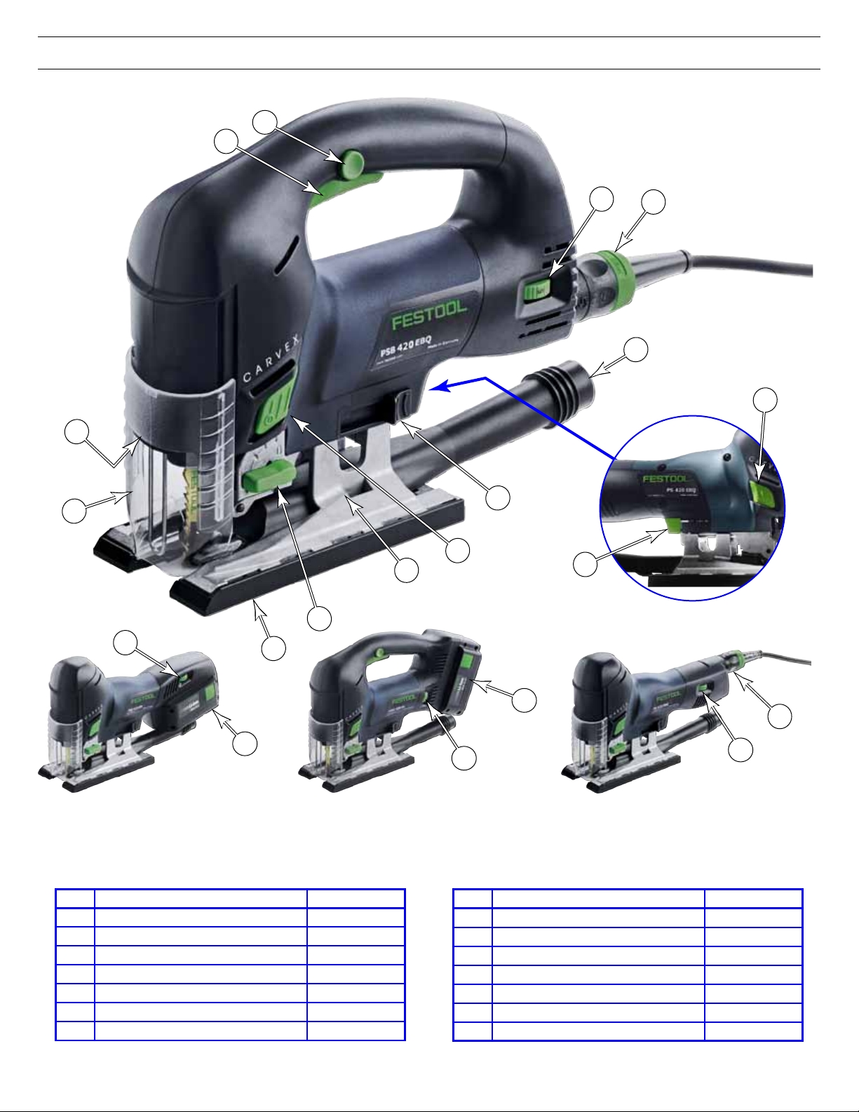
Functional Description
J
K
N
A
PSB 420 EBQ
I
H
G
Right-Side
E
F
E
D
L
C
I
B
M
PSC 420 EB PSBC 420 EB
Item Name or Description Ref. Page(s)
A Chip Guard 15
B Base Insert 9
C Pendulum Lever 10
D Main Base 10
E Left & Right Power Switch 13, 18
F Blade Release Lever 8
G Dust Collection Port 9, 15
M
H
I
I
PS 420 EBQ
Item Name or Description Ref. Page(s)
H Plug-It Power Cord Port 12
I Speed Control 13
J Trigger Release 13
K Variable Speed Trigger 13
L Base Release Lever 10
M Battery 11
N LED Work Lights 18
6 Carvex PS420 Series
Page 7

Intended Use
The Carvex jigsaw, is designed for sawing of wood, wood-
like materials, and plastics. With special saw blades offered
by Festool, the saw may also be used for cutting aluminum,
steel, non-ferrous metals, and ceramic. The tool should
not be altered or used for any other purpose, other than
as specied in these operating instructions. Using the tool
in contravention to this manual will void your warranty and
may lead to injury. The user shall be responsible and liable
for damages and accidents resulting from misuse or abuse
of this saw.
Technical Specications
Jigsaws
PS 42O EBQ PSB 420 EBQ PSC 420 EB PSBC 420 EB
Description
Speed Range (strokes per minute) 1500-3800 1000-3800 1500-3800 1000-3800
Voltage 120 V, 50/60 Hz 10.8-18.0 VDC
Power Consumption 400 W N/A
Stroke Length 26 mm (1.02")
Pendulum Stroke Off plus 3 orbit settings
Maximum Depth of Cut
(with appropriate blade)
Bevel Angle 0° to 45° both sides, with optional angle base
Weight 1.9 kg (4.2 lbs) 1.8 kg (4.0 lbs) w/o battery
Wood 120 mm (4.72")
Aluminum 20 mm (0.79")
Steel 10 mm (0.39")
Barrel Grip
Corded
D-Handle
Corded
Barrel Grip
Battery
D-Handle
Battery
Batteries and Charger
The battery powered jigsaws can be operated using any
Festool BPC or BPS class battery pack, from 10.8 volts to
18.0 volts. The TRC 3 battery charger is capable of charging
any Festool BPC or BPS class battery pack from 7.2 volts to
18.0 volts.
TRC 3 Battery Charger
Input voltage 120 V, 60Hz
Output Voltage 7.2 to 18.0 VDC
Rapid Charge Rate 3 A max.
Maintenance Charge Rate 0.06 A, pulsating
LiIon Charging Rates
Permitted charging Temperature -5°C to +45°C (23°F to 113°F)
Available Batteries BPC 15 Li BPC 18 Li
Voltage 14.4 V 18 V
Capacity 3.0 Ah 3.0 Ah
Weight 0.55 kg (1.21 lb) 0.67 kg (1.48 lb)
1.5 Ah 25 Min to 80%, 36 Min to 100%
3.0 Ah 55 Min to 80%, 70 Min to 100%
Supplemental Owner’s Manual 7
Page 8

Setup
Changing the Sawblade
The Carvex jigsaw features tool-free blade changing. Used
blades can be ejected from the saw without touching the
potentially hot blade. New blades are inserted into the
holder with just a simple twist.
Choosing the correct sawblade for the task is important
for optimal results. Refer to “Sawblade Selection” on page
14.
WARNING! Always disconnect the saw from the
power supply (power cord or battery) before making
any adjustments to the saw or installing or removing the blade.
CAUTION! After prolonged use, the used sawblade
may be hot. Take care not to touch the sawblade
until it has cooled.
Diagonal
Slot
1. Unplug the saw or remove the battery. This procedure
may require you to touch the blade with your ngers, so
make sure the saw cannot start unexpectedly.
2. If the splinter guard is installed, remove it as described
on page 12.
3. Slide the blade release lever forward until the blade is
ejected from the spring loaded holder.
4. Place the new blade into the diagonal slot on the blade
holder, press it fully in, and rotate the blade until it locks
into place. If the blade does not rotate easily, it is not
pressed in far enough. The small tabs on the side of the
blade must be inside the blade holder.
5. Adjust the blade guide as described below.
Adjusting the Blade Guide
The Carvex jigsaw features a lower blade guide to ensure
that the blade stays straight and true in the cut. If the
blade was guided only by the blade holder, like many other
jigsaws, the upper half of the blade could ex, which would
make it more likely that the blade wouldn’t be perpendicular
to the workpiece. For longer life, the blade guide is carbide
tipped to reduce wear.
WARNING! Always disconnect the saw from the
power supply (power cord or battery) before making
any adjustments to the saw or installing or removing the blade.
Blade
Release
► Take care not to over-tighten the adjustment screw. If
the jaws are too tight to the blade, you will have excessive wear on the jaws, and it may even prevent proper
pendulum action.
► If the jaws are too loose, the blade won’t be well guided
in the cut.
► For optimal adjustment, you should be able to wiggle
the blade side-to-side just a little bit.
1. Unplug the saw or remove the battery. This procedure
may require you to touch the blade with your ngers, so
make sure the saw cannot start unexpectedly.
2. Install a blade in the saw.
3. Remove the Main Base as described on page 10.
4. Using the provided 2.5 mm hex key, loosen the adjust-
ment screw enough to ensure the blade ts loosely
between the jaws of the blade guide.
5. Carefully push back on the blade to ensure it is tting
between the parallel faces of the blade guide jaws.
6. While wiggling the blade back and forth, tighten the
adjustment screw until the jaws are almost touching the
blade.
8 Carvex PS420 Series
Guide
Jaws
Adjustment
Screw
2.5 mm
Hex Key
Page 9

Changing Base Inserts
The standard Carvex base can be tted with one of 5
optional base inserts (shown below). Each base insert is
described below.
► Standard Insert: This is a general purpose insert that is
supplied with the saw, and may be used in all applications.
► Felt Insert: The felt insert provides a soft felt surface
to the base of the jigsaw for mar-free cutting on nished
materials. The bottom of the felt insert has a tight hook&-loop surface that holds the replaceable/disposable felt
pads in place.
Standard Insert
Felt Insert w/
Replaceable Felt
Dimpled Insert
► Phenolic Insert: This insert provides a smooth, hard,
and low-friction base for abrasive environments that could
scratch softer inserts.
► Dimpled Insert: This insert is designed to provide
smooth operation on rough surfaces, such as rough-sawn
lumber. The dimples (rounded studs) glide over and
between the rough features of the workpiece surface.
► Stainless Steel Insert: This insert is ideal for working on
steel, aluminum, and other very hard materials that would
scratch even the phenolic insert.
Phenolic Insert
Stainless Steel Insert
NOTE: The optional Base Accessory Kit may include
a small key and lanyard. This is for a
European conguration to lock the power
button, and is not used in North America.
1. Remove the dust collection port as described below. The
release tab on the base insert cannot be pressed in when
the dust collection port is in place.
2. Either remove the main base from the saw as described
on page 10, or remove the sawblade described on
page 8.
3. Press down on the back of the release tab and slide the
base insert forward about 1/2 inch.
4. Lift the base insert off the main base to remove it.
Release
Tab
Installing/Removing the Dust Collection Port
The dust port is used to connect a dust extractor to the
jigsaw. Refer to “Using Dust Extraction” on page 15.
It may be used with the standard base or the guide rail
base. However, the dust port cannot be used with the
angled base. See page 10 for more information on the
different bases.
► To remove the dust port from the base, press down on the
release tab and slide the port out from the base.
► To install the dust port, slide it into the base until the
release tab clicks into place.
Base
Insert
Release
Tab
Dust
Port
Supplemental Owner’s Manual 9
Page 10

Changing the Main Base
Three bases are available for the Carvex jigsaw. The bases
can be installed and removed without tools.
► Standard Base: The Carvex saw comes equipped with
the standard base and standard base insert. The standard
base is used to mount any of the optional base inserts
described on page 9. The standard base can be used
with or without dust collection.
► Guide Rail Base: The guide rail base, also called the
adapter base, is used to guide the saw using either a
NOTE: Make sure the guide rail base is installed par-
allel with the blade by wiggling it side to side before
closing the release lever. If it is installed with a slight
skew to the saw blade, it may cause the saw to drift
off the cutting line when using the saw with a guide
rail or trammel.
Festool guide rail, or the Festool trammel (for cutting
circles). The guide rail base can be used with or without
dust collection. For more information, refer to “Using the
Jigsaw with a Guide Rail” on page 15 or “Using the
Trammel to Cut Circles” on page 16.
► Angle Base: The angle base is used for making bevel cuts
with the jigsaw. The two pads can be angled from +45° to
-45°. For more information, refer to “Making Bevel Cuts”
on page 17.
Angle BaseGuide Rail BaseStandard Base
WARNING! Always disconnect the saw from the
power supply (power cord or battery) before making
any adjustments to the saw or installing or removing the blade.
1. Unplug the saw or remove the battery to prevent accidental startup.
2. Rotate the base release lever outward until the clamp is
clear of the main base.
3. Lift the main base off the bottom of the saw.
Setting the Pendulum Stroke
A conventional jigsaw moves the blade up and down in a
straight line. A pendulum jigsaw moves the blade in an
orbital motion. On the downstroke, the blade is guided
away from the cut, and on the upstroke, the blade is guided
toward the cut.
The Carvex jigsaw has 4 settings for the pendulum stroke,
ranging from a wide orbit to no obrbit (straight up and
down). Because a jigsaw cuts only on the upstroke,
this orbital type of motion is more efcient.
The orbital motion allows the saw to cut more aggressively and improves the life of
the blade. However, the larger
the orbit and more aggressive
the cut, the rougher the cut
may be.
To change the pendulum stroke,
rotate the lever to settings
0 (off) through 3 (maximum
orbit). The lever/setting may be
changed regardless whether the
saw is running or not.
10 Carvex PS420 Series
0
3
Base Release
Lever (open)
Use a larger orbit (higher number) for aggressive cutting in
softer materials. Use a smaller orbit, or no orbit, for harder
materials such as harder woods, metals, ceramics, etc.; or
when smoother cuts are desired. Also, when cutting thinner
materials, a lower orbit setting may produce better results.
The pendulum stroke should be set to zero when using a
tungsten carbide blade.
Pendulum
Motion
Gap
Clamp
Up/Cutting StrokeDown/Clearing Stroke
Guide
Roller
Page 11

Installing/Removing the Battery
The battery powered Carvex jigsaws (PSC 420 EB and PSBC
420 EB) use a removable BPC-series 18V LiIon battery pack
for their power. However, if needed, the saw may also be
powered using any BPC or BPS series battery from 12 to 18
volts. However, performance may be reduced when using a
smaller battery.
WARNING! Do not use any battery clips to hang
a jigsaw from your tool belt or waistband. The saw
can start unexpectedly, causing serious personal
injury. If a battery has the battery clip installed, it is
recommended to remove the clip to prevent it from
catching on objects during operation.
To install the battery, slide it into the receptacle on the rear
of the saw until it clicks into place. To remove the batter,
press in on both left and right release buttons, and slide the
battery out of the receptacle.
Release
Button
Charging the Battery
Battery equipped Carvex saws include a TRC 3 intelligent
battery charger. This charger may be used to charge any
Festool BPC (LiIon) or BPS (NiCd, NiMH) series battery. The
charger is microprocessor controlled and will detect the
type of battery being charged as well as the condition of the
battery.
To charge a battery, slide it onto the battery slot until it is
fully seated. The status light will change when the charger
detects the presence of the battery (fully seated). The
meanings of the status light indications are listed below:
► Yellow, Steady: Charger is ready, no battery present.
► Green, Rapid Flash: The battery is being charged at its
maximum charging rate.
► Green, Slow Flash: The battery is approaching full
charge and is being charged at a reduced charging rate.
► Green, Steady: The battery is fully charged.
► Red, Flashing: General fault indication, such as faulty
battery pack or faulty connection to battery.
► Red, Steady: The battery temperature is too high to
safely charge. Charging will commence when the temperature returns to a lower level.
Battery
Slot
Status
Light
After the battery has been fully charged, the intelligent
charger will switch to a maintenance mode to maintain a
full charge on the battery. The battery may be left in the
charger until needed. However, it is not recommended to
leave a battery in the charger for long-term storage.
For infrequently used batteries, overall battery life will
be improved if they are stored with a partial charge, and
recharged only before needed.
Supplemental Owner’s Manual 11
Page 12

Connecting the Plug-It Power Cord
The corded Carvex jigsaws (PS 420 EBQ and PSB 420 EBQ)
come equipped with a removable Plug-It power cord. The
cord can be removed for easier storage of the tool. The
Plug-It port on the PS 420 EBQ model can also be rotated
when used inverted under a workpiece, or for tting in
tighter corners.
To install the power cord, insert the cord into the inlet (port)
on the tool with the key and keyway aligned, and twist the
locking ring ¼-turn until it clicks. Reverse the procedure to
remove the cord.
NOTICE: Make sure to fully tighten the plug-it cord
a full quarter-turn until it clicks. If the plug is not
fully locked, the socket and cord can overheat and be
damaged.
NOTE: The 18 gauge plug-it cord is interchangeable
with other tools that use the same size cord, but it
cannot be used with larger tools, such as routers and
saws. The plug has an extra key to prevent it from
being used on a larger tool that would otherwise
damage the cord. Larger cords may be used with
smaller tools, but not the reverse.
Key &
Lock
Unlock
Keyway
Locking
Ring
Installing the Splinter Guard
The clear plastic splinter guard serves as a zero-clearance
throat along the blade to reduce splintering of the topside of
the workpiece. The splinter guard is a consumable component that is replaced when it wears or when blades of
different thicknesses are used.
WARNING! This procedure requires the saw to be
powered and in operation during a portion of the
installation procedure. Care must be taken to pre-
vent personal injury. Remove the battery or unplug
the saw when instructed to do so.
Plug-It
Cord
Port rotates on
PS 420 EBQ
model.
Plug-It
Port
1. Unplug the saw or remove the battery to prevent
accidental starting.
2. Rotate the pendulum stroke lever to the zero position.
3. Slide the plastic splinter guard onto the ribs on the main
base, but not far enough to touch the blade.
4. Turn the saw on, and press the front of the splinter guard
against a table to allow the sawblade to cut into the
splinter guard as it slides the rest of the way on the base.
5. For added life, as the splinter guard wears, you can push
it farther back into the base until the gap is gone.
Ribs
Gap
Grooves
12 Carvex PS420 Series
Page 13

Setting the Variable Speed
The speed of the saw can be varied from 1500 to 3800
strokes per minute. The two D-handle models have a
broader speed range of 1000 to 3800 strokes per minute
when the variable speed trigger is utilized.
The Carvex jigsaws also include an automatic speed setting,
designated with an “A” on the speed dial. In this setting, the
saw will operate at maximum speed during a cut, but will
operate at a reduced speed before the blade makes contact
with the workpiece. This reduced speed makes it easier to
line up the sawblade with your cut line at the beginning of
your cut.
To set the speed of the saw, rotate the speed dial to the
desired setting from 1 to A. The speed may be adjusted
while the saw is running.
For the D-handle models, the speed control dial acts as a
maximum speed limit when the variable trigger is used. The
more you press in on the variable trigger, the faster the saw
will operate, until it reaches the speed setting of the speed
dial.
The optimal speed of the saw is somewhat subjective, but is
predominately determined by the type of material being cut.
The actual speed that delivers the best results for a specic
cut may depend on other factors, such as blade type, workpiece brittleness, desired smoothness of cut, etc. The table
to the right provides a general guideline for blade speeds,
but your actual speeds may vary (“A” indicates maximum
speed).
Material Speed
Soft wood products and veneer plywoods 4-A
Hard wood products 3-A
Plastic laminate countertops 4-A
Hard plastics 3-A
Soft plastics 1-4
Plaster and cementitious hardboard 2-A
Aluminum, Ceramic 3-5
Steel 1-4
Variable
Trigger
Speed
Dial
Turning on the Saw
All saw models have power switches on the left and right
side of the main housing. The D-handle saws also have a
variable speed trigger in the handle.
To use the power switches on the barrel, slide either switch
forward to start the saw, and then release the switch. The
saw will continue to run until you slide either of the switches
forward again.
► The speed of the saw will be determined by the speed
control dial described above.
► It is not necessary to hold the switch forward while the
saw is running.
► Either switch may be used to turn the saw on or off.
Right Power
Switch
To use the variable speed trigger on a D-handle model,
press in on the trigger release and pull up on the trigger.
► The speed of the saw will be controlled by how much the
trigger is pulled, but the speed control dial determines the
maximum available speed.
► It is not necessary to continue to hold the trigger release
button, but it is necessary to continue to hold the trigger
depressed for the saw to run.
► The automatic speed control function is not available when
the trigger is used.
Trigger
Release
Variable
Trigger
Left Power
Switch
Supplemental Owner’s Manual 13
Page 14

Sawblade Selection
Festool sawblades are designed for optimal performance in
a variety of applications. Choosing the correct sawblade is
important for obtaining the best cuts and optimal blade life.
There are several factors that determine which blades are
best suited for the operation.
Some of the important parameters for choosing the best
blade are length, tooth shape, tooth spacing, tooth set, and
type of metal used for the blade body and teeth.
Blade Usage
The shank of Festool sawblades are color coded according to
their general usage intention. These colors are listed below.
The specialty blades are an exception in that each blade
will have its own special purpose and material type. These
include carbide tipped blades, ceramic cutting blades, and
serrated foam blades.
Wood Plastic
Blade Length
Metal
Specialty
other metals used for the blade bodies.
► Tungsten carbide abrasive blades are used for cutting very
hard materials, such as ceramics. These types of blades
cut in an abrasive or ling type of action.
► Serrated blades are used for cutting very soft materials,
such as building foam. The blade functions much like a
knife in its cutting action.
Angle Ground
Straight Ground
NOTICE: Always use a saw blade that is long enough
Carbide Tipped
to fully cut through the workpiece. Never attempt to
make a partial-depth cut with a jigsaw. Attempting to
make a cut with a saw blade that is too short to fully
cut the workpiece will likely damage the blade and
possibly the saw itself.
Tungsten Carbide Abrasive
It is important to use a saw blade that is the correct length
for the material being cut. Because part of the sawblade
never extends below the sole plate of the jigsaw, the blade
length must be greater than the thickness of the workpiece
to be cut.
Serrated
The length of a jigsaw blade is specied by the length of the
body that contains teeth, but does not include the upper
shank that ts inside the blade holder. The example below
shows a 75 mm blade. The usable length of this blade is
approximately 54 mm (2⅛"), which is 75 mm minus the 19
mm that does not extend below the saw’s sole plate, minus
the distance of the lowest tooth from the tip of the blade.
75mm
Tooth Set
The term “tooth Set” refers to whether the teeth of the
blade extend out past the body of the blade. This permits
the kerf of the blade’s cut to be wider than the body of the
blade, which reduces the likelihood of the blade binding in
the cut or overheating due to friction.
► Conical ground blades (also called tapered or trapezoidal
blades) do not have any set in their teeth, but the body of
the blade is ground to be narrower that the width of the
teeth. These blades provide very smooth cuts because the
teeth are not set side-to-side from the body of the blade,
19mm
Usable Length
Approx. 54 mm
Tooth Type
Saw blades will have different types of teeth depending
on the purpose of the blade and the type of material it is
expected to cut.
► Angle ground teeth are the most common type of teeth
for wood cutting applications. These teeth have sharpened
sides as well as sharp points to provide effective side cutting of the teeth, and not just the tips.
► Straight ground teeth are more typical for plastic and
metal cutting blades, but some wood cutting blades may
also have straight ground teeth. The tips of the teeth are
but the body of the blade still has some clearance within
the saw kerf.
► Side Set teeth are when each individual tooth is alter-
nately bent to the left or right of the blade body. This
results in the kerf width to be wider than the blade body,
and also makes these blades more aggressive in their cutting action. However, the wider the tooth set, the rougher
the cut surface will be.
► Wavy set teeth are used almost exclusively for ne-tooth
blades, such as metal cutting or ne scroll blades. The
teeth are so close together that it is not possible to put
a set on each tooth separately, so the teeth are set in
groups with a waving pattern down the length of the body.
No Set
the primary cutting edges for the blade.
► Carbide tipped blades provide for longer blade life.
Side Set
Carbide is a harder metal that does not dull as quickly as
14 Carvex PS420 Series
Page 15

Operation
Using Dust Extraction
The Carvex jigsaw can be used with or without a dust
extraction system. For best results, however, a dust extraction system (such as the Festool CT 22 shown below) should
be used. Festool dust extractors have the added features
of variable speed, and sensing when the corded model saw
is turned on. When a corded model saw is plugged into the
electrical outlet on the vacuum, the vacuum will automatically start when the saw is turned on, and will remain running for a couple of seconds after the saw turns off to clear
the remaining dust.
NOTE: A battery operated saw will not activate the
automatic function of the vacuum. The vacuum will
have to be activated manually.
NOTE: The Angled Base (see page 10) does
not permit the dust collection port to be installed.
Therefore, dust collection will not be available.
1. To use the dust extraction system, install the dust collection port as described on page 9.
2. For improved air ow of the vacuum, slide the chip guard
down.
Chip
Guard
Slide
3. Slide the vacuum hose over the dust collection port. The
outside diameter of the port is approximately 27 mm.
Vacuum
Hose
Dust
Collection Port
4. For corded models, plug the jigsaw into the electrical
receptacle on the front of the dust extractor, and turn the
power switch to “Auto”.
► When the power switch is in the manual or off position,
the electrical outlet will not have any power.
5. For cordless models, turn the power switch to manual.
Saw’s
Power Cord
Power Switch
Set to Auto
Dust
Collection Port
Using the Jigsaw with a Guide Rail
When the optional guide rail base (see page 10) is
installed on the jigsaw, the saw may be used with a Festool
guide rail for performing straight cuts. In this conguration, the distance from the rear edge of the guide rail to the
center of the blade is approximately 1⅜" (35mm).
1. Install the optional guide rail base as described on page
10.
2. Position the guide rail parallel to the desired cut line, and
1⅜” (35mm) away from the center of the cut. Note, you
will need to subtract ½ the thickness of the blade to set
the distance to the edge of the cut instead of the center
of the cut.
3. Clamp the guide rail to the workpiece.
NOTE: The body of the jigsaw does not press down
on the guide rail. To reduce the chance of slipping, it
is recommended to clamp the guide rail.
4. For best results, it is recommended to use a blade with a
wide tooth side set, such as the FSG blades.
5. Place the jigsaw base over the rear T-slot of the guide rail
and perform the cut as normal.
Guide Rail
Base
1⅜" (35mm)
Supplemental Owner’s Manual 15
Page 16

Using the Trammel to Cut Circles
The optional circle cutter (trammel) permits the jigsaw to
cut circular holes in a workpiece from the minimum and
maximum sizes shown in the table below.
Min
Inch
Radius
Diameter
The optional circle cutting trammel attachment mounts
to the underside of the optional guide rail base (see page
10). The circle cutting attachment contains the following
features:
► Built-in tape guide showing the cutting radius from 46 mm
to 1500 mm.
► Clamping knob to lock the trammel at the desired radius.
► Index pointers and trammel points for either right- or left-
hand mounting to the jigsaw base.
► Trammel points for either clockwise or counterclockwise
cutting directions.
► Trammel point pin with on-tool storage location.
1 59 46 1500
3⅝ 118 92 3000
Clamping
Knob
Max
Inch
Min
mm
Trammel Point
Pin Storage
Max
mm
Clockwise
Trammel Point
Index
Pointers
1. Identify the location of the center of the arc or circle you
wish to cut.
2. Drill a 4mm (5/32") hole at the center of the arc or circle.
3. Loosen the clamping knob and extend the tape measure
until the index pointers are pointing to the desired radius.
The radius is 1/2 the diameter of a circle.
4. Retighten the clamping knob.
5. Insert the trammel point pin through the trammel point
of the circle cutter, and into the hole you drilled into the
workpiece above.
► There are 2 trammel points on the circle cutter. One is
for clockwise rotation and the other for counterclockwise
rotation. Use the trammel point that is directly across
from the sawblade when the circle cutter is mounted to
the jigsaw.
6. Install the desired sawblade into the saw. If the radius/
diameter of the cut is small, use a scrolling sawblade. For
larger diameter circles, the high side set teeth of the FSG
blades will probably work best.
7. Install the guide rail base on the saw as described on
page 10.
8. If you are cutting a full circle, you will need a starting
point for the sawblade that lines up with your circle.
a. Using a pencil and the cutting indicator, trace out a
portion of the circle where you will manually begin
cutting.
b. Drill a hole on the waste-side of your circle large
enough to insert the sawblade into.
c. Use this starting hole to manually begin cutting the
circle—just enough to get the sawblade lined up with
the cut.
9. Place the jigsaw onto the circle cutter and continue with
the cut.
10. Before completing the cut, make sure that both the
waste piece and the saved piece are supported.
Counterclockwise
Trammel Point
Cutting
Indicator
Guide Rail
Base
Underside
of Jigsaw
16 Carvex PS420 Series
Page 17

Making Bevel Cuts
Bevel cuts may be made with the optional angle base. The
angle base provides bevel angles up to 48° to the left and
to the right. It can also function on both inside and outside
corners for edge registration.
To adjust the bevel angle, rotate the adjustment knob on
the rear of the angle base. Rotating the knob clockwise
raises the bevel feet. Rotating the knob counterclockwise
lowers the bevel feet.
Down
Bevel
Feet
Up
Adjustment
Knob
For setting the approximate angle, the angle base includes
a built-in angle indicator that shows the angle between the
base and the blade.
Indicator
Lines
The best way of setting the bevel angle is to set the angle
between the left and right bevel feet. The angle between the
bevel feet will be twice the bevel angle.
Hint: A digital angle nder is ideal for this operation.
In the example below, the angle nder was reset to
zero when the two arms were pointing in opposite
directions (180°). The reading on the display (45°) is
twice the actual bevel angle (22.5°).
Pointer
Supplemental Owner’s Manual 17
Page 18

Maintenance and Adjustment
Right Power
WARNING! Any maintenance or repair work
that requires opening of the motor or gear housing should be carried out only by an authorized
Customer Service Center (see your dealer for
information on locating a service center).
WARNING! To reduce the risk of electrocution or
other personal injury, always unplug the tool from
the power supply outlet or remove the battery
before performing any maintenance or repair work
on the tool.
Routine Maintenance
Keep the Saw Clean
Dust and debris from some materials can be extremely
abrasive and cause components within the saw to wear
prematurely. It is important to keep moving parts cleared of
abrasive dusts.
Adjustments
Programming the LED light Function
WARNING! The stroboscopic function of the LED
light may make it difcult to determine the blade
position, or give the appearance that the blade is
not moving.
WARNING! Never look directly into the LED lights.
The lights are very bright and may damage your
vision.
The LED work lights have 3 programmable settings. These
are stroboscopic, steady-on, and off. To reduce the likeli-
hood of the bright LED lights from shining in the operator’s
eyes, the lights will automatically turn off any time the saw
is rotated slightly past vertical toward the upside down position. These three operating modes are described below:
Stroboscopic: The stroboscopic function means that the
LEDs will operate in unison with the speed of the sawblade
stroke. This synchronous operation will make the sawblade
appear stationary, instead of a blur of motion. The purpose
of this stopped-motion appearance is to make it easier to
follow a pencil line.
The stroboscopic effect is active only when the blade speed
is above approximately 2100 strokes per minute. This
means the frequency range of the light is 35 to 63 Hertz.
Steady-On: In the steady-on mode, the LED lights will be
active and steady-on anytime the saw is operating, except
when the saw is turned upside down.
Off: In this mode, the LED lights are disabled.
WARNING! Do not perform this adjustment with a
sawblade installed in the jigsaw. This adjustment
may result in the saw starting unexpectedly.
1. Remove the sawblade from the saw as described on page
8.
2. Hold the saw in such a manner that when the LED lights
turn on, they will not shine directly into your eyes.
NOTICE: Do not use compressed air to clean the
motor housing of the tool, as you could inject foreign objects into the motor through the ventilation
openings.
NOTICE: Certain cleaning agents and solvents are
harmful to plastic parts. Some of these include, but
are not limited to: Gasoline, Acetone, Methyl Ethyl
Ketone (MEK), Carbonyl Chloride, cleaning solutions
containing Chlorine, Ammonia, and household cleaners containing Ammonia.
► As a general rule, keep the saw clean of all dust and
debris. Even soft-wood dust can be abrasive over time.
► Examine all moving parts for dust and debris.
► Keep the blade area and dust extraction port clean of
debris. Debris can cause wear and reduce the effectiveness of the dust extraction system.
3. Simultaneously press and hold both left and right barrel
power switches until the saw beeps.
► If the saw turns on, turn it back off and try again.
The saw may turn on if both switches are not pressed
simultaneously.
► It will take approximately 10 seconds for the saw to
beep from the time you rst pressed the two switches.
► The LED lights may or may not come on after the saw
beeps, depending on the previous program mode.
4. When the saw beeps, release both power switches.
5. Press and release the right-hand power switch to cycle
through the 3 programming options.
► The LED lights will indicate the current program mode.
They will ash if in stroboscopic mode. They will be
steady-on for steady-on mode. They will be off for the
off-mode.
6. When the desired program mode is selected, Pres and
release the left-hand power switch to exit program-mode.
Left Power
Switch
Switch
18 Carvex PS420 Series
Page 19

Troubleshooting
Symptom Possible Causes
Motor does not start
(corded models)
Motor does not start
(cordless models)
LED work lights not
functioning properly
The saw blade will not
eject
► Check that the cord is properly plugged into an outlet.
► Make sure the Plug-it connector is properly inserted and fully tightened.
► Make sure the outlet has power. Check the circuit breaker or try another outlet.
► If used with a Festool dust extractor, make sure the selector switch is pointing to “Auto”.
The auxiliary outlet on the dust extractor has power only when the selector is at Auto.
► Inspect the power cord (including extension cords) for damage or missing prongs.
► Make sure the battery is properly charged and correctly installed on the saw. If possible,
try a different battery to determine if the problem persists.
► Verify that the LED light function is correctly programmed as described on page 18.
The LEDs have 3 programmable options for “steady-on”, “stroboscopic”, and “off”.
► The LEDs will turn off if the saw is inverted or tilted slightly past the vertical position. This
is to prevent the lights from shining into the operator’s eyes. The LEDs will resume normal operation the next time the saw is turned on while in the normal horizontal position.
► Make sure you have removed the splinter guard before attempting to eject the blade. The
blade cannot rotate with the splinter guard in place.
► Make sure to use the correct sawblade identied for use with a Carvex jigsaw. Some
blades may be too thick or have too much paint on the shank to easily slide out. If a thick
blade rotates to the eject position but does not come out, try to gently pull it out with
pliers.
► Inspect the blade holder to make sure it is in the Park position (fully retracted). If the
blade holder is not in the Park position, unplug the saw and press the tip of the blade
against a work surface to retract it.
Saw blade burns on the
rear of the blade shank
(away from the teeth)
Poor cut quality
Dust extractor will not
auto-start when the saw
starts
Additional symptoms may include: bluish discoloration of the metal, sparks emanating from
the blade guide area, the blade bends backward even under a light cutting speed.
► The blade guides are set too close for the thickness of the saw blade. Readjust the blade
guides.
► The guides should barely contact the blade without restricting the movement of the
blade.
► Note that for thinner workpieces, the blade guides can be set fairly wide without
adversely affecting the cut quality.
► Make sure to use the correct blade for the desired cut:
► Saw blades with a wide set to the teeth will cut more aggressively (faster), but will
leave more scratches in the side of the cut.
► Saw blades with fewer teeth will cut more aggressively, but may be more prone to
chipping in some woods.
► Saw blades with a wider shank (front-to-rear) cut better in a straight line, but are more
difcult for cutting tight curves.
► Don’t force the saw through the cut. Let the blade work at the speed it was intended.
► Use the correct blade speed. Too slow of a speed may result in rough cuts. Too fast can
burn the workpiece.
► If the speed of the saw is set to 1 and the saw is not yet cutting, it may not draw enough
power from the dust extractor to activate the auto-start function. The extractor should
start once the saw begins drawing more power during a cut.
► The saw’s power cord must be plugged into the extractor’s auxiliary outlet. The auto-start
feature will not function with battery powered jigsaws.
Supplemental Owner’s Manual 19
Page 20

Festool USA
400 N. Enterprise Blvd
Lebanon, IN 46052
www.festoolusa.com
Service Questions:
800-554-8741
Application Questions:
888-337-8600
 Loading...