

Page 1

TS 55 REQ
Guided Circular Saw
Guided Circular Saw
Supplemental User’s Manual
WARNING To reduce the risk of serious injury, read and understand all safety
precautions and instructions in this manual before using this tool.
Page 2

Limited Warranty
1
30 Day Money Back Guarantee
Buy with condence. If you are not completely satised, return
your tool
receive a refund of either your purchase price or the lowest
retail price at which the same item has been offered since your
date of purchase. Freight charges are not refundable.
2
to the selling dealer within 30 days and you will
1+2 Limited Warranty
Festool offers a 3 year limited warranty, one of the strongest in
the industry. This warranty is valid on the pre-condition that the
tool is used and operated in compliance with the Festool operat-
ing instructions. Festool warrants that the specied tool will be
free from defects in materials and workmanship for a term of 3
years from the date of purchase.
Conditions of 1+2 Limited Warranty
All customers receive a free extended limited warranty (1 year
+ 2 years = 3 Years) on new Festool power tools purchased
from an authorized retailer. Festool is responsible for all ship-
ping costs during the rst year of the warranty. During the
second and third year of the warranty the customer is responsible for shipping the tool to Festool. Festool will pay for return
shipping to the customer using UPS Ground Service. All warranty service is valid 3 years from the date of purchase on your
receipt or invoice. Proof of purchase may be required.
Excluded from the coverage under this warranty are: normal
wear and tear, damages caused by misuse, abuse, or neglect;
damage caused by anything other than defects in material
and workmanship. This warranty does not apply to accessory
items such as circular saw blades, drill bits, router bits, jigsaw
blades, sanding belts, and grinding wheels. Operating a tool at
a voltage or frequency different from the tool’s rating will void
the warranty. This includes the usage of the tool in combination
with a transformer. Festool does not condone nor support the
use of any non-Festool engineered, designed, and manufactured accessories or consumables with Festool products. Use of
any non-Festool products may affect performance or void the
warranty. Festool is not responsible for any damages or losses
incurred and user assumes all risk and responsibility with nonFestool derived products. Also excluded are “wearing parts,”
such as carbon brushes, lamellas of air tools, rubber collars
and seals, sanding discs and pads, and Festool gear (hats and
shirts).
1 The following is an exemplar Festool limited warranty. The actual warranty that comes
with your power tool is controlling.
2 Tool must be returned in complete and whole condition as supplied to include Systainer,
cutter, blade, power cord, etc.
The obligations of Festool in its sole discretion under this
warranty shall be limited to repair or replacement or a refund
of the purchase price for any Festool portable power tool that
is found to have a defect in materials or workmanship during
the warranty period. FESTOOL SHALL NOT BE LIABLE FOR
ANY CONSEQUENTIAL, INCIDENTAL OR SPECIAL DAMAGES
REGARDLESS OF THE THEORY OF LAW ON WHICH THE
CLAIM IS BASED. ALL WARRANTIES IMPLIED BY STATE LAW,
INCLUDING THE IMPLIED WARRANTIES OR MERCHANTABILITY
AND FITNESS FOR A PARTICULAR PURPOSE ARE HEREBY
LIMITED TO THE DURATION OF THREE YEARS.
Some states in the U.S. and some Canadian provinces do not
allow the limitations on how long an implied warranty lasts, so
the above limitation may not apply to you. This warranty gives
you specic legal rights, and you may also have other rights
that vary from state to state in the U.S. and from province to
province in Canada.
With the exception of any warranties implied by state or province law as limited above, the foregoing express limited warranty is exclusive and in lieu of all other warranties, guarantees,
agreements, and similar obligations of Festool. Festool makes
no other warranty, express or implied, for Festool portable
power tools. This warranty policy is only valid for tools that are
purchased in the US and Canada. Warranty policies of other
countries may vary when obtaining warranty service outside the
US and Canada. Some countries do exclude warranty for products bought outside their territory. Festool reserves the right to
reject the repair of any tool that is not part of the US/Canada
product line. No agent, representative, distributor, dealer, or
employee of Festool has the authority to increase or otherwise
change the obligations or limitations of this warranty.
Repairs
If your Festool power tools require repair, you must contact our
Service Department at 800-554-8741 (613-363-0169 Canada)
for authorization and address details. To expedite the repair,
please ll out and enclose the Repair Order Form. Download
the form at www.festoolusa.com (www.festoolcanada.com).
No collect shipments will be accepted. No Festool hats, shirts
or other wearables may be returned. Also contact our Service
Department at the telephone number listed above if you have
any questions about warranty claim procedures.
Returns
If you need to return your Festool tools for any reason, please
return it to the dealer from which you originally bought the tool.
Liability Statement
This product has been built to the high standards of Festool.
Please do not attempt to operate or repair this equipment without adequate training. Any use, operation, or repair in contravention of this document is at your own risk. By acceptance of
this system you hereby assume all liability consequent to your
use or misuse of this equipment. Festool assumes no liability
for incidental, special, or consequential damage of any kind.
Equipment specications, applications, and options are subject
to change at the sole discretion of Festool without notice.
Proprietary Notice
All drawings and information herein are the property of Festool,
TTS Tooltechnic Systems AG & Co. KG. All unauthorized use and
reproduction is prohibited.
Written and Illustrated by Rick Christopherson.
© 2013 TTS Tooltechnic Systems AG & Co. KG
All rights reserved. Printed in the United States of America and
Germany.
2 TS 55 REQ
Festool USA is a division of Tooltechnic Systems, LLC.
Festool is a trademark and service mark of TTS Tooltechnic
Systems AG & Co. KG
Plug-It and Systainer are registered trademarks of TTS
Tooltechnic Systems AG & Co. KG
www.festoolusa.com
Page 3

Contents
About This Manual ........................................... 3
Tool Symbols ................................................... 3
General Power Tool Safety Warnings .............. 4
Work Area Safety ..........................................4
Electrical Safety ............................................ 4
Personal Safety ............................................. 4
Power Tool Use and Care ................................ 4
Service ........................................................ 5
Specic Safety Rules for Circular Saws ................ 5
Causes and Prevention of Kickback ..................... 5
Respiratory Exposure Safety Warnings ................ 5
Functional Description ..................................... 6
Intended Use ................................................... 7
Technical Specications ..................................... 7
Setup ............................................................... 7
Setting Up a New Saw ...................................... 7
Adjusting the Guide Rail Cams ........................... 7
Trimming the Guide Rail Splinter Guard ............... 8
Installing the Outrigger Splinter Guard ................ 8
Changing the Sawblade .................................... 9
Sawblade Selection ........................................ 10
Tooth Shape ............................................... 10
Number of Teeth and Spacing ........................ 10
Hook Angle ................................................. 10
TS 55 REQ Sawblades .................................. 10
Guide Rails .................................................... 11
Tips for Choosing Guide Rail Lengths .............. 11
Joining Rails ................................................ 11
Operation ...................................................... 12
Setting the Blade Depth .................................. 12
Setting the Bevel Angle ................................... 13
Setting the Motor Speed ................................. 13
Using the Limit Stop ....................................... 14
Using Dust Extraction ..................................... 14
Connecting the Plug-it Cord ............................. 15
Turning on the Saw ........................................ 15
Applications .................................................. 16
Straight-Lining Rough Lumber ......................... 16
Crosscutting and Trimming .............................. 17
Plunge Cutting ............................................... 18
Cutting Non-Wood Materials ............................ 19
Soft Plastics ................................................ 19
Brittle Plastics ............................................. 19
Thin Aluminum ............................................ 19
Extruded Aluminum ..................................... 19
Maintenance .................................................. 20
Routine Maintenance ...................................... 20
Replacing the Guide Rail Splinter Guard ............ 21
Changing the Motor Brushes ............................ 21
Adjustments .................................................. 22
Matching Multiple Saws to Shared Guide Rails . 22
Installing the Imperial Depth Gauge ............... 23
Troubleshooting ............................................ 24
About This Manual
Save These Instructions
It is important for you to read and understand this manual. The information it contains relates to protecting YOUR SAFETY
and PREVENTING PROBLEMS. The symbols below are used to help you recognize this information.
WARNING! Indicates a potentially hazardous situation which, if not avoided, could result
in death or serious injury.
CAUTION! Indicates a potentially hazardous situation which, if not avoided, could result
in minor or moderate injury.
NOTICE: Indicates a potential situation which, if not avoided, can result in property
damage or damage to the tool.
Note: Indicates information, notes, or tips for improving your success using the tool.
Tool Symbols
V Volts
W Watts
Hz Hertz
~ Alternating Current (AC)
n
No-load Speed
o
Ø Diameter
Class II Double Insulated
Supplemental Owner’s Manual 3
Page 4

General Power Tool Safety Warnings
WARNING! Read all safety warnings and
instructions. Failure to follow the warnings and
instructions may result in electric shock, re, and/or
serious injury.
Work Area Safety
► Keep your work area clean and well lit. Cluttered or dark work
areas invite accidents.
► Do not operate power tools in explosive atmospheres, such
as in the presence of ammable liquids, gases, or dust. Power
Electrical Safety
► Power tool plugs must match the outlet. Never modify the
plug in any way. Do not use any adapter plugs with earthed
(grounded) power tools. Unmodied plugs and matching
outlets will reduce risk of electric shock.
► Avoid body contact with earthed or grounded surfaces such
as pipes, radiators, ranges and refrigerators. There is an
increased risk of electric shock if your body is earthed or
grounded.
► Do not expose power tools to rain or wet conditions. Water
entering a power tool will increase the risk of electric shock.
► Do not abuse the cord. Never use the cord for carrying, pull-
ing, or unplugging the power tool. Keep cord away from heat,
oil, sharp edges or moving parts. Damaged or entangled
cords increase the risk of electric shock.
► When operating a power tool outdoors, use an extension
cord suitable for outdoor use. Use of a cord for outdoor use
reduces the risk of electric shock.
Save all warnings and instructions
for future reference.
tools create sparks which may ignite the dust or fumes.
► Keep children and bystanders away while operating a power
tool. Distractions can cause you to lose control.
► If operating a power tool in a damp location is unavoidable,
use a ground fault circuit interrupter (GFCI) protected supply.
Use of a GFCI reduces the risk of electric shock.
► Never use an extension cord that is damaged, including cuts,
exposed wires, or bent/missing prongs. Damaged extension
cords increase the risk of re or electric shock.
► Use only extension cords rated for the purpose.
► Use only extension cords rated for the amperage of this tool
and the length of the cord. Using too small of an extension
cord can cause the cord to overheat.
Extension Cord Ratings
Cord Length Size (AWG)
<50 Ft. 14
50-100 Ft. 12
>100 Ft. Not recommended
Personal Safety
► Stay alert, watch what you are doing, and use common sense
when operating a power tool. Do not use a power tool while
tired or under the inuence of drugs, alcohol, or medication.
A moment of inattention while operating power tools may
result in serious personal injury.
► Use personal protective equipment. Always wear eye pro-
tection. Protective equipment such as dust mask, non-skid
safety shoes, hard hat, or hearing protection used for appropriate conditions will reduce personal injuries.
► Prevent unintentional starting. Ensure the switch is in the
off-position before connecting to power source, picking up,
or carrying the tool. Carrying power tools with your nger on
the switch or energizing power tools that have the switch on
invites accidents.
► Remove adjusting key or wrench before turning the power
tool on. A wrench or a key that is left attached to a rotating
part of the tool may result in personal injury.
► Do not overreach. Keep proper footing and balance at all
times. This enables better control of the tool in unexpected
situations.
► Dress properly. Do not wear loose clothing or jewelry. Keep
your hair, clothing, and gloves away from moving parts. Loose
clothes, jewelry, or long hair can be caught in moving parts.
► If devices are provided for the connection of dust extrac-
tion and collection facilities, ensure these are connected and
properly used. Use of dust collection can reduce dust-related
hazards.
► Always wear safety glasses complying with ANSI Z87.1.
Ordinary glasses are not proper protection.
Power Tool Use and Care
► Do not force the power tool. Use the correct power tool for
your application. The correct power tool will do the job better
and safer at the rate for which it is designed.
► Do not use the power tool if the switch does not turn it on
and off. Any power tool that cannot be controlled with the
switch is dangerous and must be repaired.
► Disconnect the plug from the power source before making
any adjustments, changing accessories, or storing the tool.
Such preventive safety measures reduce the risk of starting
the tool accidentally.
► Store idle tools out of reach of children and do not allow
persons unfamiliar with the power tool or these instructions
4 TS 55 REQ
to operate the power tool. Power tools are dangerous in the
hands of untrained users.
► Maintain power tools. Check for misalignment or binding of
moving parts, breakage of parts and any other condition that
may affect the power tool’s operation. If damaged, have the
power tool repaired before use. Many accidents are caused by
poorly maintained power tools.
► Keep cutting tools sharp and clean. Properly maintained tools
with sharp cutting edges are less likely to bind and are easier
to control.
► Use the power tool, accessories, and tool bits etc. in accor-
dance with these instructions, taking into account the working
Page 5

conditions and the work to be performed. Use of the power
tool for operations different from those intended could result
in a hazardous situation.
Service
► Have your power tool serviced by a qualied repair person
using only identical replacement parts. This will ensure that
Specic Safety Rules for Circular Saws
► Keep hands away from the blade and cutting area. Keep your
second hand on the auxiliary handle. If both hands are holding the saw, they cannot be cut by the blade.
► Keep your body positioned to either side of the saw blade, but
not in line with the saw blade. Kickback could cause the saw
to jump backward. (See “Causes and Prevention of Kickback”
below.)
► Do not reach underneath the workpiece. The blade is fully
exposed under the workpiece.
► Never use a plunging circular saw that fails to return to its
unplunged position. If the saw ever fails to fully retract the
sawblade as expected, immediately stop using the saw and
have the saw serviced by an authorized service center.
► Never use a dust extraction system when making cuts that
can result in sparks, such as cutting through nails and other
ferrous materials. Sparks and hot embers can cause a re or
explosion in the dust extraction system.
► To reduce the risk of serious injury, never alter or misuse the
power tool.
the safety of the power tool is maintained.
► Never hold the piece being cut in your hands or across your
leg. It is important to support the work properly to minimize
body exposure, blade binding, or loss of control.
► Hold the saw by the insulated handles when performing an
operation in which the sawblade may contact hidden wiring or
its own cord. Contact with a “live” wire will make the exposed
metal parts of the tool “live” and shock the operator.
► When ripping, always use a rip fence or straight edge guide.
This improves the accuracy of cut and reduces the chance for
blade binding.
► Always use blades with the correct size and shape arbor
holes. Blades that do not match the mounting hardware of
the saw will run eccentrically, causing loss of control.
► Never use damaged or incorrect blade anges or bolt. The
blade anges and bolt were specially designed for your saw
for optimum performance and safety of operation.
Causes and Prevention of Kickback
Kickback is a sudden reaction to a pinched, bound, or misaligned saw blade that causes the saw to lift up and out of the
workpiece toward the operator.
Chances for kickback may be reduced by taking proper precautions as described below:
► Maintain a rm grip with both hands on the saw and position
your body and arm to allow you to resist kickback forces.
Kickback forces can be controlled by the operator if proper
precautions are taken.
► When interrupting a cut for any reason, release the trigger
and hold the saw motionless in the material until the blade
comes to a complete stop. Never attempt to remove the saw
from the work or pull the saw backward while the blade is in
motion, or kickback may occur.
► When restarting a saw in the workpiece, center the saw blade
in the kerf and check that the saw teeth are not engaging the
Respiratory Exposure Safety Warnings
Substantial or repeated inhalation of dust and other airborne
contaminants, in particular those with a smaller particle size,
may cause respiratory or other illnesses. Various dusts created
by power sanding, sawing, grinding, drilling and other construction activities contain chemicals or substances known (to the
State of California and others) to cause cancer, birth defects or
other reproductive harm. Some examples of these chemicals/
substances are: lead from lead-based paints; crystalline silica
from bricks, cement, and other masonry products; arsenic and
chromium from chemically-treated lumber; and some wood
material. If the saw blade is binding during a restart, it may
climb up or kickback from the workpiece.
► Do not use a dull or damaged blade. Dull or improperly
sharpened blades cause excessive friction, blade binding, and
kickback.
► Support large panels to minimize the risk of the blade pinch-
ing and causing a kickback. Large panels tend to sag under
their own weight. Supports must be placed under the panel
on both sides, near the line of cut and near the edge of the
panel.
► The bevel adjusting knobs must be fully tightened before
making a cut. If the blade tilts during a cut, it will bind and
cause a kickback.
► Use extra caution when making a plunge cut into existing
walls or other blind areas. The protruding blade may cut
objects that can cause kickback.
dusts, especially from hardwoods, but also from some soft-
woods such as Western Red Cedar.
The risk from these exposures varies, depending on how often
you do this type of work. To reduce your exposure to these
chemicals: work in a well ventilated area and use a properly
functioning dust extraction system. When the inhalation of
dust cannot be substantially controlled, i.e., kept at or near the
ambient (background) level, the operator and any bystanders
should wear a respirator approved by NIOSH for the type of
dust encountered.
Supplemental Owner’s Manual 5
Page 6

Functional Description
F
E
G
I
R
J
K
L
D
C
G
F
H
B
A
S
I
D
O
L
M
Q
P
O
N
Item Name or Description Ref. Page(s)
A Viewing Window 8
B Arbor Bolt 9
C Spring Loaded Riving Knife --
D Miter Release Button 13
E Dust Collection Port 14
F Plunge/Trigger Release 15
G FastFix Arbor/Plunge Lock 9
H Trigger (On/Off Switch) 15
I Auxiliary Handle --
J Blade Wrench Storage 9
6 TS 55 REQ
Item Name or Description Ref. Page(s)
K Depth Stop and Gauge 12,23
L Bevel Gauge and Lock Knob 13
M Speed Control 13
N Plug-It Power Cord Port 15
O Guide Rail Cams 7,8
P Sole Plate --
Q Outrigger Splinter Guard 8,18
R Limit Stop 14,18
S Main Handle --
Page 7
Intended Use
The TS 55 REQ, hand-operated circular saw, is designed
exclusively for sawing of wood, wood-like materials, and
plastics. The saw may also be used for cutting aluminum
when a Festool aluminum-cutting sawblade is installed. The
tool should not be altered or used for any other purpose,
other than as specied in these operating instructions. Using
the tool in contravention to this manual will void your warranty and may lead to injury. The user shall be responsible
and liable for damages and accidents resulting from misuse
or abuse of this saw.
Technical Specications
Power Consumption 1200 Watts (10 amps @ 120 volts)
Speed Range 2,000 to 5,200 RPM (no load)
Blade Diameter 160 mm
Arbor Diameter 20 mm, Round
Depth of Cut (without guide rail) 55 mm (2.2”) @ 90°, 43 mm (1.7”) @ 45°
Bevel Angle 0° to 45°, plus -1° to 47°
Weight 4.5 kg (9.9 lbs)
Setup
Setting Up a New Saw
There are some simple setup procedures to follow before a
new saw can be used. Follow this sequence of inspections
and adjustments before using the saw for the rst time. It
is important that these instructions be followed sequentially
before cutting the zero-clearance splinter guards.
WARNING! Always disconnect the saw from the
power supply before making any adjustments to the
saw or installing or removing any accessory.
CAUTION! Check regularly whether the saw blade
is in good condition, and the arbor bolt is rmly
tightened. Saw blades which are cracked, damaged,
or deformed should no longer be used.
1. With the saw unplugged, inspect the blade for damage
and make sure it is properly secured to the arbor. (Refer
to “Changing the Sawblade” on page 9 for more
information).
2. Perform the guide rail gib cam adjustment procedure
described below.
3. Install the power cord into the Plug-It receptacle on the
saw (refer to page 15 for more information).
4. After completing all of the inspections and adjustments
listed above, cut the zero-clearance splinter guards as
described on page 8.
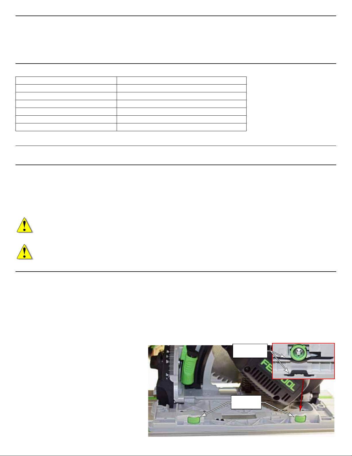
Adjusting the Guide Rail Cams
The guide rail cams tighten against the rib of the guide rail
to remove any side-play from the saw during a cut. Knobs
on the top of the cams permit easy adjustment.
1. Place the saw on the guide rail.
2. Loosen both cams by rotating the knobs
counterclockwise.
3. Working with one cam at a time, jiggle the saw side-to-
side while turning the cam clockwise until the saw ts
snugly to the rail.
4. Repeat for the second cam.
5. Make sure the cams are not over tightened by
sliding the saw down the guide rail. If the saw
does not slide easily, loosen the cams.
Supplemental Owner’s Manual 7
Notes:
► The cams do not need to be very tight for normal opera-
tions. A tiny amount of side-play will not impact the
quality of a cut.
► Over tightening the cams or operating the saw in abrasive
environments can cause premature wear of the wear
bars. Periodically inspect the wear bars for at spots, and
replace if necessary.
Replaceable
Wear Bars
Guide Rail
Cams
Page 8
Trimming the Guide Rail Splinter Guard
The leading edge of the guide rail has a replaceable, rub-
ber, zero-clearance strip. The rst time the saw is used with
the guide rail, this strip is trimmed to match the sawblade.
When trimmed to size, this strip reduces chipping and
tearout during normal cutting.
Important: If you have more than one saw that
uses the same guide rail system, you want all of the
saws to have the same cutting path. Before cutting
the splinter guard, use the “Matching Multiple Saws
to Shared Guide Rails” on page 22 to match one
saw to another before completing this procedure.
1. Set the blade depth very shallow (6 to 7 mm) so that the
blade teeth penetrate the strip by about half a tooth, as
shown.
2. Set the motor speed to 6.
3. Place the guide rail on a stable surface with the strip
hanging over the edge so you don’t cut the table.
4. If necessary, adjust the guide rail cams as described on
page 7.
5. Cut the strip in a single, smooth, low-speed rip from one
end of the guide rail to the other.
Set the blade depth so
about 1/2 a tooth is
Splinter
Guard
below the splinter guard.
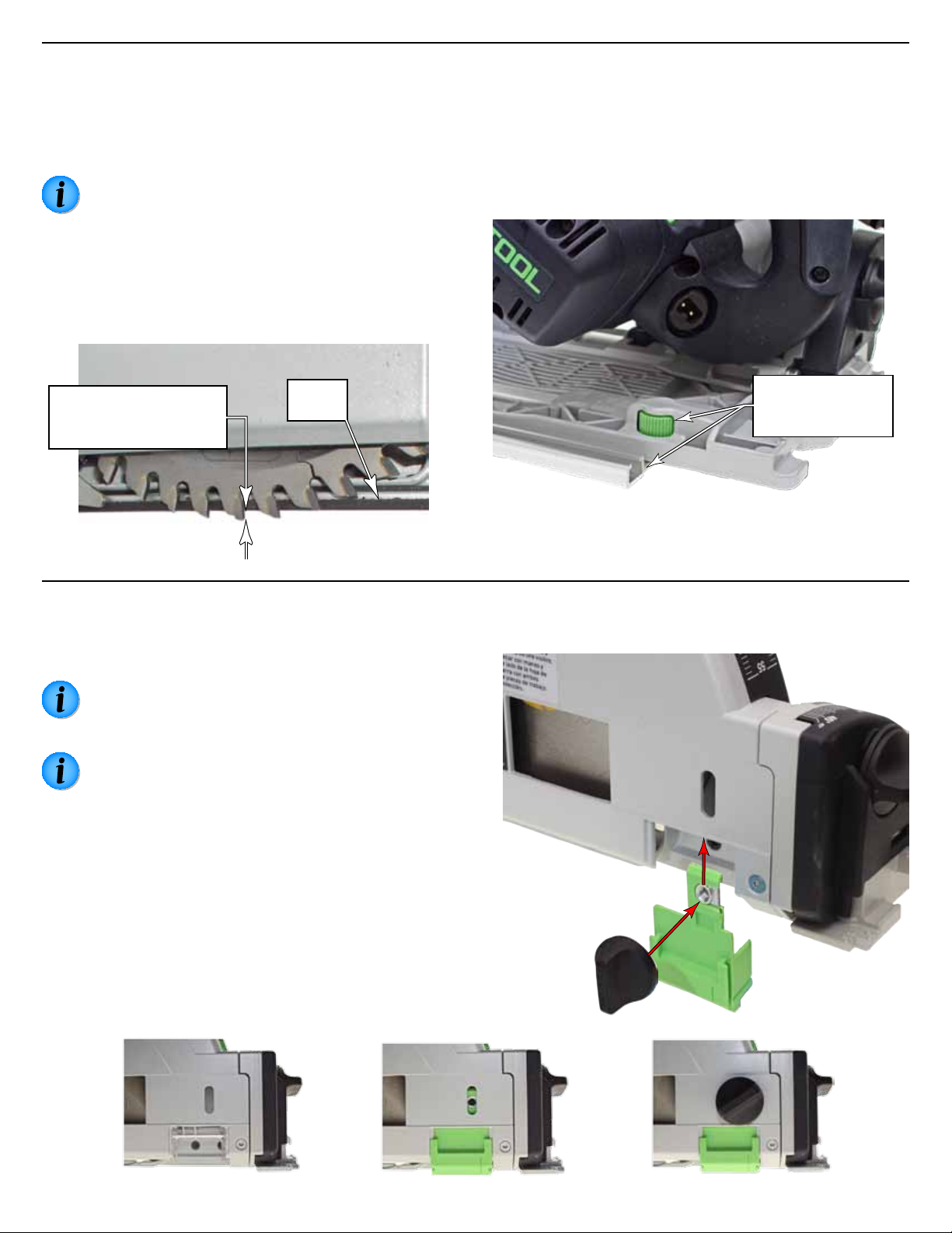
Installing the Outrigger Splinter Guard
The outrigger splinter guard is used to prevent chipping
on the offcut side of the sawblade. The outrigger can be
retracted away from the workpiece when not needed.
Note: The outrigger splinter guard is a consumable
item and will need to be replaced periodically when it
is no longer close to the blade.
Note: The rst time you use the outrigger splinter
guard, it will be trimmed to match the blade.
1. Remove the clear viewing window by pushing straight
down and sliding it out of the saw.
2. Remove the thumbscrew from the outrigger and slide
the outrigger on to the front edge of the blade guard as
shown.
3. Insert the thumbscrew through the outrigger, through the
height adjustment slot, and into the captive nut on the
back side of the outrigger.
4. Place the guiderail on the workpiece and the saw on the
guiderail.
5. Press down on the outrigger splinter guard so it is lightly
touching the workpiece, and tighten the thumbscrew.
Begin and end with
cams lined up with
guide rail ends
6. For longer life, remove the splinter guard and reinstall
the clear viewing window, when not in use.
8 TS 55 REQ
Page 9

Changing the Sawblade
The TS55 saw features the FastFix system for easier blade
changing. The FastFix system is engaged by raising the
FastFix lever and plunging the saw down. The system
includes the following features:
► For safety, the power switch is locked out.
► The plunge depth is locked in the position shown to the
right with the arbor bolt accessible through an opening in
the blade cover.
► The arbor is locked from turning.
Sawblade Checks and Warnings
► Use only sawblades that are approved for use with the
saw and appropriate for the type of material being cut.
► Use only sawblades with a diameter of 160 mm, and an
arbor bore of 20 mm.
► Do not use a sawblade that is bent or warped.
► Do not use a sawblade with missing or damaged teeth.
Removing the Sawblade
1. Unplug the saw for safety.
2. Although not required, you may wish to remove the
outrigger splinter guard for better clearance.
3. Set the blade depth guage to at least 25 mm, or below.
4. Raise the FastFix latch lever.
5. Press upward on the plunge lock release button and
plunge the saw down until it locks into position.
6. Using the arbor wrench (stored in the auxiliary handle)
loosen the arbor bolt by turning it counterclockwise.
7. Remove the arbor bolt and ange.
Hint: If you drop the arbor ange inside the blade
guard, remove the blade and the arbor ange should
come out afterward.
Plunge
Release
Arbor Bolt
and Flange
Inboard
Arbor Flange
Insert the
blade over the
riving knife.
FastFix
Lever
Depth
Gauge
Blade
Wrench
Arbor Bolt
and Flange
Alignment Keys
8. Lift the blade off the inboard arbor ange, and slide the
blade out of the blade guard over the top of the riving
knife.
Replacing the Sawblade
Festool offers a variety of sawblades for the many types of
cuts the saw can be used for. These range from ne crosscutting, ripping, and even a plastic and metal cutting blade.
Refer to “Sawblade Selection” on page 10 for information
on which blade may be best suited for the desired task.
1. Make sure the blade’s label is facing outward, and the
teeth are facing forward in the direction shown above.
2. Insert the blade into the housing, over the top of the
riving knife, and onto the arbor.
3. Make sure the blade is properly seated on the inboard
arbor ange.
Supplemental Owner’s Manual 9
4. Install the arbor ange with the alignment keys aligned
with the notches in the inboard arbor ange.
5. Firmly tighten the arbor bolt.
CAUTION! The arbor bolt is not a self-tightening
type if left too loose. Periodically check to ensure it
is rmly tightened.
Page 10

Sawblade Selection
Festool sawblades are designed for optimal performance in
a variety of applications. Choosing the correct sawblade is
important for obtaining the best cuts and optimal blade life.
There are several factors that determine which blades are
best suited for the operation.
Tooth Shape
Festool sawblades come in two primary tooth
shapes. The Alternate Top Bevel (ATB) shape is
ideal for clean cutting of wood bers. The Triple
Chip (TC) shape is very robust in holding sharpness in hard or abrasive materials.
The alternating points of the ATB blade slice
through the wood bers at the edges of the cut
to produce clean and efcient cuts. The lower
15° bevel angle of Festool blades allow them
to maintain sharpness of the points longer
between sharpenings.
The trapezoidal shape of the TC blade tooth
maintains its sharpness by not having points
that could quickly dull. Each trapezoidal tooth
initially cuts a little of the center of the cut,
and then is followed by a at-top raker tooth
to nish the cut and clean up the corners. The
TC grind is ideally suited for materials that would
otherwise quickly dull an ATB blade.
AT B
Bevel
TCG
Number of Teeth and Spacing
The more teeth a blade has, the less work each tooth has
to do by itself. This results in cleaner cuts in brous materials such as wood. It also makes the blade less aggressive
in its cutting, which is benecial in both hard materials and
brous materials.
Another aspect about tooth spacing is harmonics. If each
successive tooth strikes the workpiece in rhythm with other
teeth, it can set up vibrations in the blade and workpiece.
Festool sawblades use variable tooth spacing to prevent
harmonics from happening. The spacing between successive
teeth is constantly changing so that the frequency of successive cuts is never in a harmful rhythm.
Hook Angle
The hook angle of a sawblade is the angle
between the face of a blade tooth with
respect to a radial line to the center of
the blade. This is most obvious on ripping blades, where the high hook angle
is easily seen. The higher the hook angle,
the more aggressive the blade will cut the
workpiece. This is desired for ripping, but
it is not desired for ner cuts, and especially not for vary hard materials.
Cutting harder materials is best performed with blades with
lower hook angles. Metal cutting blades (and miter saw
blades) actually have negative hook angles to minimize their
aggressiveness in the cut. This means that the teeth are
sloped slightly backward from the radial line to the center of
the blade.
Hook
TS 55 REQ Sawblades
Fine Crosscut: 48T, ATB, 12° hook
This is the standard blade that comes
with the TS55 saw. The high tooth
count, low hook angle, and ATB design
make it optimally suited for cutting veneered plywood with minimal
tearout.
Combination: 28T, ATB, 15° hook
This blade combines the geometries of
both ripping and crosscut blades. The
higher hook angle makes it cut more
aggressive like a ripping blade, and
the moderate tooth count provides a
cleaner cut like a crosscut blade.
General Purpose: 12T, ATB, 20° hook
With a low tooth count and a high hook
angle, this blade easily cuts through
general construction materials.
Ripping: 14T, ATB, 37° hook
The high hook angle of the Panther
blade makes for effortless ripping
without burning the cut.
Fine Laminate: 48T, TC, 4° hook
The ultra-hard TCG teeth on this blade
provide chip-free cutting of laminates
and solid surface materials without
dulling.
Aluminum/Plastic: 56T, TC, -5° hook
The negative hook angle and high
TCG tooth count of this blade provides
grab-free control for cutting aluminum
and hard plastic.
10 TS 55 REQ
Page 11

Guide Rails
Guide rails come in a variety of lengths, ranging from 32
inches to 197 inches (800mm to 5000mm). It is always best
to use the correct length rail for the cut, but sometimes it
is necessary to join two smaller rails together to make a longer rail. Guide rail connecting bars are available for joining
two or more guide rails together.
Tips for Choosing Guide Rail Lengths
The length of the guide rail must be at least 10 inches
(250mm) longer than the cut to be performed. This is so
that the saw can be supported (and guided) at both the
beginning and end of the cut. The minimum position is when
the guide rail cam (page 7) is at the edge of the rail, but
still on the rail.
► The guide rail must extend at least 6 to 7 inches (depend-
ing on blade depth) ahead of the cut to allow the sawblade to be plunged without entering the workpiece.
► The guide rail must extend at least 3 inches past the cut
to allow the center of the blade to exit the workpiece.
To simplify storage or transportation, some woodworkers
prefer having two shorter rails instead of a longer rail. Other
woodworkers prefer to have single lengths for the specic
cuts they make, to minimize the frequency of needing to
join rails. Here are some tips about choosing guide rail
lengths to suit your needs:
► For frequent cutting of plywood sheets that involve both
ripping and crosscutting, dedicated guide rails of the
appropriate length may be best. This allows for switching
back and forth quickly without having to join rails.
► It’s more efcient to have guide rails of different lengths
than it is to have two guide rails of the same length. This
gives you more variety in lengths. For example, if you
had two 55 inch rails, you would have only two possible
combinations: 55 and 110 inches. However, if you had
lengths of 42 and 75 inches, for example, you would have
three combinations of lengths: 42, 75, and 117 inches.
► Shorter guide rails are easier to work with for shorter
cuts. A cabinetmaker, for example, may want dedicated
shorter guide rails for crosscutting cabinet carcase
components.
Minimum
Position at the
Start of the Cut
Minimum
Position at the
End of the Cut
Center
of Blade
Joining Rails
Note: Do not assume that butting the two rail ends
together will result in a straight line for their entire
length. A very tiny error in the butted joint can
result in a signicant error across the length of the
joined rails. A long straightedge is the recommended
method for aligning the rails.
1. Insert the two connecting bars into the T-slots on one
rail (typically the longer of the two rails). Make sure the
clamping screws are facing outward.
2. Slide the second rail over the connecting bars and push
the two rails together.
3. Place a straightedge across the joint between the two
rails, as shown to the right.
4. Center the top connecting bar across the joint, and
gently tighten the 4 clamping screws. Do not over tighten
the screws, or you may dimple the guide rail.
5. Carefully ip the guide rails over, and with the straight-
edge across the joint, tighten the bottom clamping
screws.
Supplemental Owner’s Manual 11
Upper
Connecting
Bar
Straightedge
Lower
Connecting
Bar
Clamping
Screws
Page 12

Operation
Setting the Blade Depth
The TS55 is equipped with a depth stop for setting the
depth of the blade during a plunge cut. Using the correct
blade depth improves cutting safety, cut quality, and motor
efciency.
Multi-Function Tables
When the saw is used in conjunction with a Multi-Function
Table (MFT), the blade depth is typically limited to be 2mm
deeper than the thickness of the workpiece. This limits the
amount that the blade cuts into the table.
Off-table Cutting
When the saw is used for off-table cutting, the blade can be
set deeper without cutting into the worktable. The following guidelines can be used to determine the optimal blade
depth.
Effects of Too Shallow of a Setting
► Higher drag on the sawblade, requiring more power and
effort to complete the cut.
► Increased chance for kickback.
► Increased chipping and splintering on the underside of the
cut, especially with melamine and veneers.
► Increased burning of the cut, especially in certain hard-
woods like cherry and maple.
► With the exception of underside chipping, all of these
effects are greatest with ner-toothed blades.
Effects of Too Deep of a Setting
► Increased danger with more of the blade exposed below
the workpiece.
► Increased sawtooth marks in the cut.
► Increased top-side chipping and splintering, especially
without using the guide rail and splinter guards.
with a shallower cut.
► Cutting dense and/or hard materials may require a deeper
setting to decrease heat and load on the tool.
► Cutting fragile or shatter-prone materials such as plastics
or countertop laminates is best with a shallow setting (and
low speed).
► Cutting aluminum may be improved with a semi-shallow
setting, but not too shallow.
► When Used with the Multi-Function Table (MFT) you may
wish to keep the blade depth shallower.
► Cutting non-fragile, non-shattering plastics such as poly-
propylene or solid-surface countertops may be improved
with a deeper cut.
► More aggressive blades, such as the Panther ripping
blade, can be used at a shallower setting.
Using the Depth Stop
The depth stop has two index pointers 5mm apart. One is
used to indicate the blade depth when used without a guide
rail, and the other is used to indicate the blade depth when
used with a guide rail.
The TS 55 REQ also includes an optional imperial (inch)
depth gauge sticker. Refer to “Installing the Imperial Depth
Gauge” on page 23 for instructions on installing the
sticker.
► To change the depth setting, press in on the index pointer
and slide it up or down to the desired setting.
► When precise depth control is needed, rotate the ne
adjustment screw using the blade wrench. This is typically
needed only when making trenching cuts.
Depth Without
Guide Rail
Blade Depth Recommendations
There are no set rules for setting the depth of the blade with
Depth With
Guide Rail
respect to the underside of the cut. However, a common
industry guideline is to have the gullets of the blade even
with the underside of the workpiece. This will therefore be
Fine
Adjustment
used as a baseline to describe optional depth settings.
Press In
Gullet
► If a material is prone to burning in the cut, increase the
depth slightly. This includes ripping hardwoods such as
cherry and maple.
► Using a combination blade in solid wood may perform
better with a slightly deeper setting.
► Using a coarse blade in sheet materials may be improved
12 TS 55 REQ
to Slide
Page 13

Setting the Bevel Angle
The standard bevel range of the TS 55 REQ is between 0˚
and 45˚. However, an extended range is also available from
-1˚ to 47˚. The extended range is available by pulling out
on the limit release knob.
Bevel
Guage
Index
Pointer
1. Loosen the front and rear bevel thumbscrews.
2. Tilt the saw until the index pointer is aligned with the
desired angle. To go above or below the normal limit
stops, pull out slightly on the limit release knob.
3. Retighten both bevel thumbscrews.
Rear
Thumbscrew
Front
Thumbscrew
Setting the Motor Speed
The TS55 has electronic speed control with soft-start
circuitry. The electronic controller will maintain the motor
speed even as the load changes. The speed control is
innitely variable from 2000 to 5200 RPM. The optimal
speed of the saw is predominately determined by the type
of material being cut.
Turn the speed control dial to the number shown in the table
below.
Material Speed
Soft wood products and veneer plywoods 6
Hardwood products 3-6
Plastic laminate countertops 6
Hard plastics 3-5
Soft plastics 1-4
Plaster and cementitious hardboard 1-3
Aluminum 4-6
Limit
Release
Speed
Control
Supplemental Owner’s Manual 13
Page 14

Using the Limit Stop
The limit stop serves two purposes: it controls the saw’s
starting position and prevents a kickback during a plunge
cut. The leading edge of the limit stop prevents the saw
from lifting up at the beginning of a plunge cut. This is what
prevents kickback during a plunging operation. Refer to
“Plunge Cutting” on page 18 for more information.
1. Slide the limit stop onto the T-slot of the guide rail
behind the saw, and with the embossed arrow pointing
toward the saw.
2. Position the stop behind the starting position of the saw.
► When the blade is at full-depth, the limit stop is 3¾
inches behind the start of the cut.
► When the blade is less than full depth, the distance
between the blade (cut) and the limit stop will be
greater.
► For best results, you should always verify the blade’s
cutting position before staring the cut.
3. Tighten the thumbscrew on the limit stop.
Using Dust Extraction
The TS55 can be used with or without a dust extraction
system. The chip diverter swivels to direct the sawdust away
from the work area when a dust extraction system is not
used.
For best results, however, a dust extraction system (such
as the Festool CT 22 shown below) should be used. Festool
dust extractors have the added features of variable speed,
and sensing when the saw is turned on. The vacuum will
automatically start when the saw is turned on, and will
remain running for a couple of seconds after the saw turns
off to clear the remaining dust.
Saw’s
Power Cord
Power Switch
Set to Auto
Clamping
Thumbscrew
Limit
Stop
Back of
Saw
Guide Rail
T-Slot
1. Insert the extractor hose on to the chip diverter.
► The 27mm Festool hose ts inside the diverter, and the
36mm Festool hose ts over the diverter.
► The diverter ID is 35mm (1⅜”), and the OD is 39mm
9
(1
⁄16”).
2. Plug the TS 55 power cord into the auxiliary outlet on the
extractor (if so equipped).
3. Set the power switch on the extractor to “Auto.” (The
auxiliary power outlet is active only when the switch is
set to Auto.)
27mm
Vac Hose
14 TS 55 REQ
Page 15

Connecting the Plug-it Cord
The TS55 saw comes equipped with a removable Plug-It
power cord. To install the power cord, insert the cord into
the inlet on the tool with the key and keyway aligned, and
twist the locking ring. Reverse the procedure to remove the
cord.
NOTICE: Make sure to fully tighten the plug-it cord
a full quarter-turn until it clicks. If the plug is not
fully locked, the socket and cord can overheat and be
damaged.
Plug-It
Port
Locking
Ring
Key &
Keyway
Lock
Unlock
Turning on the Saw
To prevent unexpected start-ups, the power switch has an
integral safety interlock. Before the saw can be started or
plunged, the plunge release must be engaged.
To start the saw, push up on the plunge release, and pull
back on the trigger. Once the trigger has been engaged, you
no longer need to hold the plunge release raised.
Plunge &
Trigger Release
Power
Trigger
A Note About Motor Sound
Most circular saws do not have variable speed electronic
controls like the TS55 has. For this reason, many new saw
owners aren’t accustomed to the slight “growling” sound
of the motor’s gears when they rst operate the saw. This
sound is normal and not an indication that something is
wrong with the tool.
The sound is the result of the gears interacting with the
electronic speed control. The electronic controller in the
motor controls the motor speed by turning it On and Off
very rapidly. This form of speed control is called “Pulse
Width Modulation” (PWM), and is common in most power
tools with a variable speed control. When there is little or
no load on the sawblade, the pulsations of the motor cause
the gears to rapidly engage and disengage (called lash), and
this is the sound you are hearing.
Supplemental Owner’s Manual 15
Page 16

Applications
The TS55 is capable of performing a wide variety of tasks.
The following sections provide information on some of these
tasks. This is intended to be an introduction to the capabili-
Straight-Lining Rough Lumber
Purchasing lumber directly from a saw mill is signicantly
less expensive than buying from a home center. However,
part of the reason why the lumber is less expensive is
because it frequently has not been straight-line ripped.
Sawmills have special straight-line ripping tablesaws, but
they charge an extra fee for the service, and straight-lining
on a regular tablesaw is complicated.
The TS55 can quickly and easily straight-line rough lumber
using the guide rail. Additionally, if the grain of the wood is
diagonal with the cut edge, the TS55 can be used to re-cut
the lumber on a diagonal to match the natural wood grain
direction or to avoid defects.
Tips for Successful Straight-Lining
► Use the correct blade for the cut. The Panther ripping
blade will provide the easiest cutting in any hardwood.
A coarse combination blade may be used for softwoods,
or for a ner edge, but it will take more effort to rip the
wood.
ties of the saw, but should not be considered as a comprehensive list of its capabilities.
► Choosing a blade depth: When ripping hardwood lumber,
there is a trade off between cutting power and cutting
quality. A deeper blade setting takes less energy, but a
shallower blade setting typically leaves a ner cut.
► A dedicated ripping blade, such as the Panther, is
aggressive enough in cutting power that it may be used
with a shallow cutting depth.
► For a less aggressive combination blade, you may need
to set the depth a little lower to reduce the power
demand on the blade.
► Choose the orientation of the guide rail to optimize the
board usage. This may have several different options:
► Align the cut with the natural wood grain orientation.
► Align the cut to avoid defects in the wood.
► Align the cut to maximize board width, while eliminating
curved edges.
► Place the board on sawhorses or elevate it from a work
table so you do not cut into your work table.
Long Guide Rail or
Joined Shorter Rails
Guide Rail
Positioned to
Maximize Yield
Tree
Bark
Panther
Rip Blade
Elevate
Workpiece
16 TS 55 REQ
Page 17

Crosscutting and Trimming
No other saw on the market can outperform a Festool
for splinter-free, ne crosscutting. With other saws, the
problem is two-fold; getting a straight cut, and achieving a splinter-free cut. The TS55 handles these problems
effortlessly.
Tips for Successful Crosscutting
► Use the correct blade for the cut.
► Crosscutting ne veneered wood should use the ne
crosscut blade. The Alternate-Top-Bevel teeth will slice
the wood bers best, with virtually no chipping.
► Crosscutting soft lumber, or lumber-core veneers should
use the ne crosscut blade or the combination blade.
With fewer teeth than the ne crosscut blade, the
combination blade will be more aggressive for cutting,
yet still provide good chip-free cutting.
► Crosscutting thick hardwood lumber, and difcult to cut
lumber should use the coarse crosscut blade. The coarse
tooth-count of this blade provides very aggressive cut-
ting of difcult material, but won’t provide as smooth of
a nish as the ner blades.
► Cutting plastic-veneer countertops or solid surface
materials should use the ne laminate blade. The Triple-
Chip-Grind of this blade lasts longer in hard materials
and reduces chipping in man-made materials. The
triple-chip-grind will provide good cuts in wood veneers,
but not as good as the alternate-top-bevel ne crosscut
blade.
► For small offcuts, overhang the workpiece from a work
table or saw horses (as shown below). For larger offcuts,
support both the primary piece and the offcut.
► If the offcut is reusable, use the outrigger splinter guard
to prevent chipping.
► Make sure the workpiece is secure. The lightweight door
shown in the example below would slide on the table if not
clamped down.
► Make sure the guide rail is secure if it can move during the
cut. In the example below, starting the cut with the saw
behind the workpiece can cause the guide rail to tip up
and move. (The guide rail clamps are below the guide rail,
and not visible.)
► Don’t start the cut by plunging the saw into the wood, as
this can lead to tearout at the bottom-back of the sawblade. Start the cut with the blade down and behind the
workpiece (as described on page 11), and advance the
saw forward into the cut.
► Setting the blade depth too shallow (just barely penetrat-
ing the underside of the workpiece) can cause tearout on
the underside of the cut.
Festool Dust
Extractor
Veneer
Door
Workpiece
Clamp
Fine Cross-
cut Blade
Workpiece
Overhangs Table
Supplemental Owner’s Manual 17
Page 18

Plunge Cutting
CAUTION! Never make a plunge cut without a limit
stop. The back of the sawblade will lift the saw off
the guide rail, and will result in a kickback situation.
Plunge cutting is used when the cut does not start at the
edge of the workpiece. Instead, it starts in the middle of the
workpiece, and may continue to the end, or may stop short
of the end. There is a wide variety of applications for plunge
cuts. Some examples include cutting a countertop for a sink
or appliance, cutting a hardwood oor for inset tile, slotting a
cabinet frame for a pull-out bread board; just to name a few.
Notes
► Always use the limit stop when making a plunge cut to
prevent an unexpected kickback (see page 14).
► Whenever possible, put the guide rail on the side of the
cut that will be saved. If the guide rail is placed on the
offcut side, you must remember to account for the blade
thickness when positioning the guide rail (typically 2.2
mm).
► Whenever possible, set the saw depth to its maximum
setting to minimize the amount of material that is not cut
by the blade. Make sure there is nothing below the cut
that you don’t want to cut into.
Full Blade
Depth
Shallow
Blade Depth
Manually cut
the corners.
► Mark the beginning and end of the cut (blue tape in
picture below). If the blade is at full depth, there are
index marks on the saw that indicate where the blade is
positioned.
► For 4-sided cuts where the center section is removed,
support the offcut piece before cutting all four sides to
prevent it from breaking the corners. Trim the corners
with a handsaw.
► To control the position of the saw at both the beginning
and end, you may use a second limit stop (part number
491582) at the front of the saw, as shown below.
Rear blade
position at
full depth.
Front blade
position at
full depth.
General Procedure
1. Using pencil lines, tape, or some other means, mark the
beginning and end of the cut.
2. Place the guide rail on the cutline.
3. Place the saw on the guide rail, and position it at the
start of the cut.
4. Install the limit stop on the guide rail, slide it up to the
back of the saw, and lock it in place.
5. If an optional second limit stop is used, set its position in
a similar manner.
6. With the saw rmly seated against the beginning limit
stop, start the saw and slowly plunge it down.
7. Advance the saw through the cut until the end is
reached.
► Hold the saw fully plunged until the blade comes to a
complete stop.
► Never back the saw up, as this can result in a kickback.
Optional 2nd
Limit Stop
Limit
Stop
Splinter Guard
Mark the beginning
and end of cut.
18 TS 55 REQ
Page 19

Cutting Non-Wood Materials
Soft Plastics
Soft plastics such as polypropylene won’t chip, but they will
melt. Therefore, a more aggressive cut with the blade set
deeper and the motor speed set low will reduce the melting.
► Too shallow of a blade depth and the plastic will be more
prone to melting.
► Too deep of a blade depth and the teeth marks from the
blade will be more prevalent.
► Any of the ne-tooth blades with a slow motor speed will
cut this material with good results.
► Clean up the cut edges with a cabinet scraper.
Brittle Plastics
Brittle plastics will both melt and chip, so cutting them is
problematic with most other saws. The TS55 works great for
cutting this type of material.
► Set the blade depth very shallow to reduce chipping.
► Set the motor speed very low to reduce melting.
► Use any one of the ner tooth blades for good results, but
the negative hook aluminum and plastic blade provides
the best results.
► In clear plastics such as acrylic, if the cut is milky white,
it is a sign of melting. Note how the cut to the right is
transparent.
Thin Aluminum
The problem with cutting thin aluminum sheet is that the
blade teeth can catch the edge of the sheet, and cut more
aggressively than expected. To reduce this, you want the
teeth moving nearly parallel with the aluminum surface (a
shallow blade depth).
► The ultra-thin aluminum shown in the example was cut
best with the ne crosscut blade. The positive hook angle
of the blade kept the exible aluminum tight to the guide
rail in a sheering cut.
► For slightly thicker, less exible pieces of aluminum, the
negative hook angle, aluminum cutting blade works best
because it cuts less aggressively.
Extruded Aluminum
Care needs to be taken when cutting extruded aluminum
because the blade may cut more aggressively than expected
on the various surfaces of the stock. This is most noticeable
with thin-walled extrusions.
► With thin-walled extrusions, try to keep the blade teeth
traveling parallel to the walls (see image above) to reduce
aggressiveness.
► With thick-walled extrusions, try to keep the blade teeth
traveling slightly more perpendicular to the walls (see
image to the right) to decrease loading.
► Use the negative hook angle, aluminum-cutting blade, and
a moderate to high speed setting.
► Be prepared for the blade to catch unexpectedly as the
cutting angle changes with each facet of the extruded
shape.
Supplemental Owner’s Manual 19
Page 20

Maintenance
WARNING! Any maintenance or repair work
that requires opening of the motor or gear housing should be carried out only by an authorized
Customer Service Center (see your dealer for
information on locating a service center).
WARNING! To reduce the risk of electrocution or
other personal injury, always unplug the tool from
the power supply outlet before performing any
maintenance or repair work on the tool.
Routine Maintenance
Keep the Saw Clean
Dust and debris from some materials can be extremely
abrasive and cause components within the saw to wear
prematurely. It is important to keep moving parts cleared of
abrasive dusts.
► As a general rule, keep the saw clean of all dust and
debris. Even soft-wood dust can be abrasive over time.
► Examine all moving parts for dust and debris.
► Keep the bevel hinges clean of dust using compressed
air or cotton swabs. If the hinges wear due to abrasive
particles, the saw will not perform optimally.
► Keep the blade area and dust extraction port clean of
debris. Debris can cause wear and reduce the effectiveness of the dust extraction system.
► Periodically remove the blade cover (5 screws), the blade,
and the inboard arbor ange; and clean any built up
debris from the inside of the saw.
NOTICE: Do not use compressed air to clean the
motor housing of the tool, as you could inject foreign objects into the motor through the ventilation
openings.
NOTICE: Certain cleaning agents and solvents are
harmful to plastic parts. Some of these include, but
are not limited to: Gasoline, Acetone, Methyl Ethyl
Ketone (MEK), Carbonyl Chloride, cleaning solutions
containing Chlorine, Ammonia, and household cleaners containing Ammonia.
Keep the Sawblades Sharp
Using a dull sawblade can be extremely dangerous and
provide poor cut quality.
► Never attempt to sharpen a sawblade manually. Special
equipment is necessary to properly sharpen a circular
sawblade. An improperly sharpened sawblade can injure
the operator, destroy the saw, and damage the workpiece.
► The sawblades should be sharpened regularly, and only by
a qualied sharpening service.
► Improper grinding of the carbide teeth of a sawblade can
result in serious injury to the saw operator.
Adjust and Inspect the Saw
To ensure the saw is in proper working order, periodically
inspect the operation of the saw and ensure it is properly
adjusted.
► Observe the function of the saw during normal operation.
► Unusual sounds are indicative of pending problems.
► A reduction in the cut quality indicates the saw is either
improperly adjusted or not functioning properly.
► A reduction in cutting power or speed may indicate a dull
blade or a motor problem.
► If any of the safety devices on the saw are inoperable
or disabled, immediately stop using the saw and have it
serviced.
► Periodically inspect the wear bars for the guide rail cams
for wear.
20 TS 55 REQ
Page 21

Replacing the Guide Rail Splinter Guard
The splinter guard prevents splintering and chipping of the
workpiece by holding the top edge of the workpiece down
as the teeth of the sawblade move upward against it. The
splinter guard needs to be replaced if it becomes damaged
or worn.
1. Peel the original splinter guard away from the guide rail.
2. As needed, clean residual adhesive and debris from the
guide rail.
3. Peel off the plastic backing from the new splinter guard
to expose the adhesive.
4. Without stretching the rubber, carefully place the new
splinter guard on the underside of the guide rail tight to
the alignment rib.
5. Make sure the splinter guard is rmly pressed down to
Changing the Motor Brushes
Festool does not condone brush replacement by the end
user. Completion of this procedure by an unauthorized
service center will void the tool’s warranty.
The motor brushes are graphite bars that provide an electrical connection between the motor controller and the rotat-
ing armature. When the brushes have worn past their useful
length, spring loaded wear pins are exposed that separate
the brush from the armature contacts. This disables the
motor to prevent damage. For a shorter break-in period
without excessive arcing, new brushes have ribs that quickly
form to the curve of the armature.
CAUTION! Make sure the power cord is unplugged
before beginning this procedure.
the guide rail.
6. Trim the splinter guard as described on page 8.
Splinter
Guard
Friction
Strips
Alignment Rib
Wear Pin
Used Brush
Terminal
Spade
Mounting
New Brush
Tab
Procedure
1. Unplug the saw.
2. Remove the four screws that secure the access cover to
the motor, and remove the cover.
Mounting
Screws
3. Lift the 2 wire connectors off the terminals on the
brushes.
4. Remove the screw that secures each brush to the motor
housing. Be careful not to drop the screws into the motor.
5. Carefully lift the brushes up to remove them.
6. Insert the new brushes into the motor, and reassemble
the saw by reversing the previous steps.
Mounting
Screw
Wire
Terminal
Wire
Terminal
Mounting
Screw
Thermal
Sensor
NOTICE: Take care to not pull on the red wires for
the thermal sensor, or you may pull the sensor out
of its pocket. The sensor is embedded in a thermally
conductive paste.
Supplemental Owner’s Manual 21
Page 22

Adjustments
Matching Multiple Saws to Shared Guide Rails
If you own multiple saws that share common guide rails,
you will want all of your saws calibrated to the same blade
position. This will prevent one saw from cutting more guide
rail splinter guard than another saw.
Note: Depending on the cutting position of your
existing saw(s), it may be necessary to match your
existing saws to the cutting position of the TS 55
REQ. To prevent excessive misadjustment of the saw,
the TS 55 REQ limits the blade position adjustment to
be within 0.030” of the factory calibration. Older generation saws were not limited, and could potentially
be misadjusted beyond specication. If your existing
saws are adjusted beyond specication, they should
be adjusted to match the TS 55 REQ.
1. Place a workpiece on a stable surface, and overhanging
the edge so the saw blade can be set to maximum depth.
► For best results, the workpiece should be a near-homog-
enous material, such as a tight grained wood or Medium
Density Fiberboard (MDF).
► The workpiece can be any length, as long as it is at least
slightly longer than the saw.
► The thickness of the workpiece is not critical, but you
may have best results if it is between ¾” and 1¼”
2. Securely clamp a guide rail to the workpiece, so that the
guide rail will remain stationary as you switch between 2
or more saws.
► Clamping the guide rail is important. If the guide rail
moves during this procedure, you will have to start over.
3. Set the blade depth for all saws to their maximum depth.
4. Using the primary saw that you want your other saw(s)
to match, cut the workpiece using a full-depth plunge.
Note: Before adjusting a saw, you should rst verify
whether it needs adjustment. Check the saw’s position using the procedure below, except do not loosen
the adjustment screws.
5. Unplug all saws for safety.
6. Slightly loosen the 4 bevel block mounting screws from
the underside of the saw. (These are located on the top
side of TS 55 EQ and TS 75 EQ saws.)
7. Note: The TS 55 REQ FastFix has a second stop position
which is near full depth. To activate it, plunge the blade
to full depth, then open the FastFix lever, and release the
plunge until it clicks in place.
8. Without moving the guide rail, place the saw to be
adjusted on the guide rail, and press against a forward
tooth until it is touching the workpiece edge.
9. Insert a 0.15mm (0.006”) feeler gauge between a rear
tooth and the workpiece, and press the tooth against the
gauge/workpiece. If a feeler gauge is not available, a
piece of paper folded in half will equal 0.004” to 0.006”.
Touching
Feeler
Workpiece
Gauge
10. For the TS 55 EQ or TS 75 EQ saws, carefully tighten all
4 bevel block mounting screws; taking care to not move
the blade position in the process.
11. For the TS 55 REQ:
a. Carefully tighten the 2 forward bevel block mounting
screws. These are double-ended screws that are also
accessible from above the saw using a 2mm hex key.
Note that they turn counterclockwise to tighten from
above.
b. To tighten the rear bevel block mounting screws, care-
fully slide the saw to the rear of the guide rail until the
screws are accessible from below.
Top Side of
Mounting Screws
Mounting
Screws
Thumbscrew
removed for clarity
22 TS 55 REQ
Page 23

Installing the Imperial Depth Gauge
The TS 55 REQ comes with an optional imperial depth gauge
sticker to replace the standard metric depth gauge.
1. Set the depth gauge pointer to its maximum setting.
2. Using a sharp pencil, carefully mark the zero-depth position of the depth gauge on the blade housing.
Mark the zerodepth position.
5. Taking care not to kink the sticker, tuck the bottom under
the depth gauge pointer.
6. Make sure the sticker is properly aligned along the edge
of the blade cover, peel back more of the paper backing,
and press the sticker down.
7. Raise the depth pointer back toward zero, peel back the
rest of the paper backing, and nish adhering the rest of
the sticker.
Peel back
more of the
paper backing.
3. Peel back no more than 1/3 of the paper backing from
the top of the sticker. Peeling the paper back at a slight
angle (as shown) will reduce the likelihood of kinking the
sticker later.
Important: Notice that the top of the sticker has the
zero-depth indicator, and the numbers increase as
they go down.
4. Carefully position the sticker over the existing gauge with
the zero-depth aligned with the pencil mark you made
above, and straight along the edge of the blade cover.
Align with
pencil mark.
Paper
Backing
Tuck the
sticker under
the pointer.
Supplemental Owner’s Manual 23
Page 24

Troubleshooting
Symptom Possible Causes
Motor does not start
e saw makes a
“Growling” sound when
it is rst turned on or
idling.
e saw makes wavy
cuts
Saw cuts are burning
► Check that the cord is properly plugged into an outlet.
► Make sure the Plug-it connector is properly inserted and fully tightened.
► Make sure the outlet has power. Check the circuit breaker or try another outlet.
► If used with a Festool dust extractor, make sure the selector switch is pointing to “Auto”.
The auxiliary outlet on the dust extractor has power only when the selector is at Auto.
► Inspect the power cord (including extension cords) for damage or missing prongs.
► The motor brushes may have worn and need replacement.
► This is normal operation. Refer to page 15 for more information.
► Make sure the guide rail gib cams are properly adjusted.
► Inspect the blade for damage.
► Make sure the sole plate is not rocking on the guide rail.
► Keep the blade depth consistent during the cut; don’t raise and lower the blade.
► Forcing an ATB-type blade into the cut too fast can cause the blade to deect.
► Make sure to use the correct blade for the material.
► Make sure the blade is sharp.
► Make sure the blade is installed correctly (not turning backward).
► Reduce the motor speed.
► If possible, increase the blade depth.
► Increase your feed speed.
Excessive chipping on
the lower edge of the cut
Excessive chipping on
the top edge of the cut
e sawblade fails to
retract aer a cutting
operation
► Make sure to use the correct blade for the type of material and type of cut.
► A very shallow blade depth can cause chipping on the underside if the teeth are barely
protruding below the surface. Increase the blade depth.
► The blade toe-in may be incorrect. Refer to page 22 for more information.
► Make sure to use the correct blade for the type of material and type of cut.
► Inspect the splinter guard. Make sure it is ush with the cut line for its entire length.
► Materials prone to splintering may splinter more if the blade is set too deep.
► The saw requires immediate service, and should be removed from operation. Contact
Festool or your authorized Festool service provider.
24 TS 55 REQ
Page 25

Supplemental Owner’s Manual 25
Page 26

Festool USA
400 N. Enterprise Blvd
Lebanon, IN 46052
www.festoolusa.com
Service Questions:
800-554-8741
Application Questions:
888-337-8600
 Loading...