

Page 1
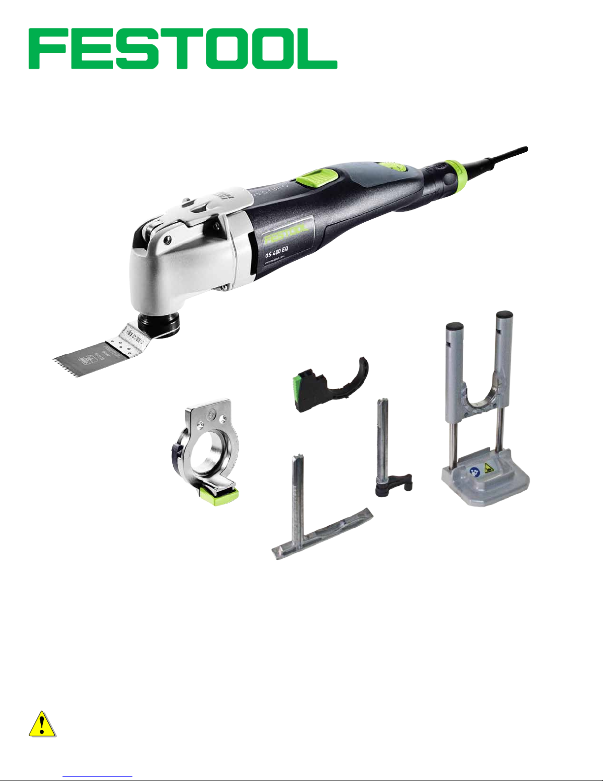
Vecturo
Multi‑Purpose
Oscillating Tool
OS 400 EQ
Supplemental User’s Manual
WARNING To reduce the risk of serious injury, read and understand all safety
precautions and instructions in this manual before using this tool.
Page 2

Limited Warranty
1
30 Day Money Back Guarantee
Buy with condence. If you are not completely satised, return
your tool
receive a refund of either your purchase price or the lowest
retail price at which the same item has been offered since your
date of purchase. Freight charges are not refundable.
2
to the selling dealer within 30 days and you will
Service All-Inclusive® Warranty
Festool USA warrants that all new Festool power tools� purchased from authorized dealers in the U.S. and Canada will be
free from defects in materials and workmanship for a term of
three years from the date of original retail purchase.
Conditions of Service All-Inclusive Warranty
This warranty applies for three years from the date of original
retail purchase. Proof of purchase is required. This warranty is
void if the tool is not used, operated, repaired and maintained
in accordance with the tool’s instruction manual.
Excluded from this warranty’s coverage are:
► Accessories and/or attachments, including, but not limited to,
saw blades, drill bits, router bits, sanding discs and apparel
► Tools purchased from outside of the U.S. or Canada
► Repairs or replacements not performed by an authorized
Festool Service Center, outside of routine maintenance as set
forth in the instruction manual
► Parts or components not supplied by Festool or that have
been modied
► Damage caused by misuse, abuse, accident, impact, abnor-
mal wear and tear, improper storage and/or exposure to the
elements, or neglect
► Damage caused by anything other than defects in materials
and workmanship
► Normal adjustments and recommended maintenance as set
forth in the tool’s instruction manual
► Damage from the operation of the tool at a voltage or fre-
quency different from the tool’s rating, including the use of
transformers
1 The following is an exemplar Festool limited warranty. The actual warranty that comes
with your power tool is controlling.
2 Tool must be returned in complete and whole condition as supplied to include Systainer,
cutter, blade, power cord, etc.
3 For purposes of this warranty, power tools are dened as any Festool branded product
that bears a serial number (S.Nr. or M.Nr.).
4 To determine if your application is excluded from the warranty under this condition,
please contact the Festool Service Center at 800.554.8741
Repairs
If your Festool power tool requires repair, whether it be
warranty or non-warranty, you must contact our Service
► Damage resulting from the use of any non-Festool accessories
or attachments
► Tools used in high volume industrial applications⁴
Should any failure covered by this Limited Warranty occur, the
purchaser must contact Festool through our website, www.
festoolusa.com/SAI, or call 888.337.8600 for authorization and
shipping information. For purchases made in Canada, contact
our website, www.festoolcanada.com/SAI or call 613.363.0169.
Festool, in its sole discretion, may elect to repair, replace or
refund the purchase price of any tool covered by this Limited
Warranty that is found to be defective, at no cost to the purchaser. Warranty returns will be processed by Festool according
to normal work ow and availability of replacement parts and
components. Festool will issue a prepaid shipping label for
return of the tool to the Festool Service Center and will also
return the repaired tool freight prepaid, if the repair or replacement is covered under this Limited Warranty.
FESTOOL SHALL NOT BE LIABLE FOR ANY CONSEQUENTIAL,
INCIDENTAL OR SPECIAL DAMAGES REGARDLESS OF THE
THEORY OF LAW ON WHICH THE CLAIM IS BASED. ALL
WARRANTIES IMPLIED BY STATE LAW, INCLUDING THE
IMPLIED WARRANTIES OF MERCHANTABILITY AND FITNESS
FOR A PARTICULAR PURPOSE ARE HEREBY LIMITED TO THE
DURATION OF THREE YEARS.
SOME STATES IN THE U.S. AND SOME CANADIAN PROVINCES
DO NOT ALLOW EXCLUSIONS/LIMITATIONS OF INCIDENTAL
OR CONSEQUENTIAL DAMAGES AND/OR LIMITATIONS ON
HOW LONG AN IMPLIED WARRANTY LASTS, SO THE ABOVE
LIMITATION MAY NOT APPLY TO YOU. THIS WARRANTY GIVES
YOU SPECIFIC LEGAL RIGHTS, AND YOU MAY ALSO HAVE
OTHER RIGHTS THAT VARY FROM STATE TO STATE IN THE U.S.
AND FROM PROVINCE TO PROVINCE IN CANADA.
With the exception of any warranties implied by state or
province law as limited above, the foregoing limited warranty is
exclusive and in lieu of all other warranties, guarantees, agreements, and similar obligations of Festool. No agent, representative, distributor, dealer, or employee of Festool has the authority
to increase or otherwise modify the obligations or limitations of
this warranty.
Warrantor:
Festool USA Phone: USA—888.337.8600
Festool Canada Canada—613.363.0169
400 N Enterprise Dr. festoolusa.com/SAI
Lebanon, IN 46052 festoolcanada.com/SAI
Department at 888-337-8600 (613-363-0169 Canada) for
authorization and address details.
Liability Statement
This product has been built to the high standards of Festool.
Please do not attempt to operate or repair this equipment without adequate training. Any use, operation, or repair in contravention of this document is at your own risk. By acceptance of
this system you hereby assume all liability consequent to your
use or misuse of this equipment. Festool assumes no liability
for incidental, special, or consequential damage of any kind.
Equipment specications, applications, and options are subject
to change at the sole discretion of Festool without notice.
Proprietary Notice
All drawings and information herein are the property of Festool,
TTS Tooltechnic Systems AG & Co. KG. All unauthorized use and
reproduction is prohibited.
Written and Illustrated by Rick Christopherson.
© 2014 TTS Tooltechnic Systems AG & Co. KG
Festool USA is a division of Tooltechnic Systems, LLC.
2 Vecturo OS 400 EQ Multi-Tool
Festool is a trademark and service mark of TTS Tooltechnic
Systems AG & Co. KG
Plug-It and Systainer are registered trademarks of TTS
Tooltechnic Systems AG & Co. KG
www.festoolusa.com
Page 3

Contents
About This Manual ........................................... 3
Tool Symbols ................................................... 3
General Power Tool Safety Warnings .............. 4
Work Area Safety ..........................................4
Electrical Safety ............................................ 4
Personal Safety ............................................. 4
Power Tool Use and Care ................................ 4
Service ........................................................ 5
Specic Safety Rules for Multi-Tools .................... 5
Respiratory Exposure Safety Warnings ................ 5
Multi-Tool Overview ........................................ 5
Intended Use ................................................... 5
Technical Specications ..................................... 5
Functional Description ...................................... 6
Setup ............................................................... 7
Changing Blades .............................................. 7
Installing the Accessory Adapter ........................ 8
Installing the Depth Stops ................................. 8
Installing the Plunge Base ................................. 9
Connecting the Plug-It Power Cord ................... 10
Setting the Speed Control ............................... 10
Power Switch ................................................. 10
Operation ...................................................... 11
Cutting Blade Principles .................................. 11
Cutting Blade Selection ................................... 12
Wood-Cutting, Japanese-Style Blades ............. 12
Universal Wood/Composite Blades ................. 12
Metal Cutting Blades .................................... 12
Linear Cutting Circular Blades ....................... 12
Scraper Blades ............................................ 12
Cutting Speed Selection .................................. 12
Maintenance and Adjustment ........................ 13
Routine Maintenance ...................................... 13
Troubleshooting ............................................. 13
Motor Brush Replacement ............................... 14
About This Manual
Save These Instructions
It is important for you to read and understand this manual. The information it contains relates to protecting YOUR SAFETY
and PREVENTING PROBLEMS. The symbols below are used to help you recognize this information.
WARNING! Indicates a potentially hazardous situation which, if
not avoided, could result in death or serious injury.
CAUTION! Indicates a potentially hazardous situation which, if
not avoided, could result in minor or moderate injury.
NOTICE: Indicates a potential situation which, if not avoided,
can result in property damage or damage to the tool.
Note: Indicates information, notes, or tips for improving your
success using the tool.
Tool Symbols
V Volts
W Watt s
Hz Hertz
~ Alternating Current (AC)
n
No-load Speed
o
Class II Double Insulated
Supplemental Owner’s Manual 3
Page 4

General Power Tool Safety Warnings
WARNING! Read all safety warnings and
instructions. Failure to follow the warnings and
instructions may result in electric shock, re, and/or
serious injury.
Work Area Safety
► Keep your work area clean and well lit. Cluttered or dark work
areas invite accidents.
► Do not operate power tools in explosive atmospheres, such
as in the presence of ammable liquids, gases, or dust. Power
Electrical Safety
► Power tool plugs must match the outlet. Never modify the
plug in any way. Do not use any adapter plugs with earthed
(grounded) power tools. Unmodied plugs and matching
outlets will reduce risk of electric shock.
► Avoid body contact with earthed or grounded surfaces such
as pipes, radiators, ranges and refrigerators. There is an
increased risk of electric shock if your body is earthed or
grounded.
► Do not expose power tools to rain or wet conditions. Water
entering a power tool will increase the risk of electric shock.
► Do not abuse the cord. Never use the cord for carrying, pull-
ing, or unplugging the power tool. Keep cord away from heat,
oil, sharp edges or moving parts. Damaged or entangled
cords increase the risk of electric shock.
► When operating a power tool outdoors, use an extension
cord suitable for outdoor use. Use of a cord for outdoor use
reduces the risk of electric shock.
Save all warnings and instructions
for future reference.
tools create sparks which may ignite the dust or fumes.
► Keep children and bystanders away while operating a power
tool. Distractions can cause you to lose control.
► If operating a power tool in a damp location is unavoidable,
use a ground fault circuit interrupter (GFCI) protected supply.
Use of a GFCI reduces the risk of electric shock.
► Never use an extension cord that is damaged, including cuts,
exposed wires, or bent/missing prongs. Damaged extension
cords increase the risk of re or electric shock.
► Use only extension cords rated for the purpose.
► Use only extension cords rated for the amperage of this tool
and the length of the cord. Using too small of an extension
cord can cause the cord to overheat.
Extension Cord Ratings
Cord Length Size (AWG)
<50 Ft. 14
50-100 Ft. 12
>100 Ft. Not recommended
Personal Safety
► Stay alert, watch what you are doing, and use common sense
when operating a power tool. Do not use a power tool while
tired or under the inuence of drugs, alcohol, or medication.
A moment of inattention while operating power tools may
result in serious personal injury.
► Use personal protective equipment. Always wear eye pro-
tection. Protective equipment such as dust mask, non-skid
safety shoes, hard hat, or hearing protection used for appropriate conditions will reduce personal injuries.
► Prevent unintentional starting. Ensure the switch is in the
off-position before connecting to power source, picking up,
or carrying the tool. Carrying power tools with your nger on
the switch or energizing power tools that have the switch on
invites accidents.
► Remove adjusting key or wrench before turning the power
tool on. A wrench or a key that is left attached to a rotating
part of the tool may result in personal injury.
► Do not overreach. Keep proper footing and balance at all
times. This enables better control of the tool in unexpected
situations.
► Dress properly. Do not wear loose clothing or jewelry. Keep
your hair, clothing, and gloves away from moving parts. Loose
clothes, jewelry, or long hair can be caught in moving parts.
► If devices are provided for the connection of dust extrac-
tion and collection facilities, ensure these are connected and
properly used. Use of dust collection can reduce dust-related
hazards.
► Always wear safety glasses complying with ANSI Z87.1.
Ordinary glasses are not proper protection.
Power Tool Use and Care
► Do not force the power tool. Use the correct power tool for
your application. The correct power tool will do the job better
and safer at the rate for which it is designed.
► Do not use the power tool if the switch does not turn it on
and off. Any power tool that cannot be controlled with the
switch is dangerous and must be repaired.
► Disconnect the plug from the power source before making
any adjustments, changing accessories, or storing the tool.
Such preventive safety measures reduce the risk of starting
the tool accidentally.
► Store idle tools out of reach of children and do not allow
persons unfamiliar with the power tool or these instructions
4 Vecturo OS 400 EQ Multi-Tool
to operate the power tool. Power tools are dangerous in the
hands of untrained users.
► Maintain power tools. Check for misalignment or binding of
moving parts, breakage of parts and any other condition that
may affect the power tool’s operation. If damaged, have the
power tool repaired before use. Many accidents are caused by
poorly maintained power tools.
► Keep cutting tools sharp and clean. Properly maintained tools
with sharp cutting edges are less likely to bind and are easier
to control.
► Use the power tool, accessories, and tool bits etc. in accor-
dance with these instructions, taking into account the working
Page 5

conditions and the work to be performed. Use of the power
tool for operations different from those intended could result
in a hazardous situation.
Service
► Have your power tool serviced by a qualied repair person
using only identical replacement parts. This will ensure that
Specic Safety Rules for Multi-Tools
► Know the material you are cutting or abrading and take
precautions accordingly. Some materials contain chemicals,
elements, or bers which may be toxic or harmful when cut,
abraded, or heated. Take caution to prevent dust or vapor
inhalation and skin contact.
► Do not use in wet environments. Ingestion of water into the
motor may result in electrocution hazard.
► Hold the tool by insulated gripping surfaces when perform-
ing an operation where the cutting tool may contact hidden
wiring or its own cord. Contact with an energized wire will
make exposed metal parts of the tool energized and shock
the operator.
► To reduce the risk of re, explosion, or electric shock, always
Respiratory Exposure Safety Warnings
Substantial or repeated inhalation of dust and other airborne
contaminants, in particular those with a smaller particle size,
may cause respiratory or other illnesses. Various dusts created
by power sanding, sawing, grinding, drilling and other construction activities contain chemicals or substances known (to the
State of California and others) to cause cancer, birth defects or
other reproductive harm. Some examples of these chemicals/
substances are: lead from lead-based paints; crystalline silica
from bricks, cement, and other masonry products; arsenic and
chromium from chemically-treated lumber; and some wood
► To reduce the risk of serious injury, never alter or misuse the
power tool.
the safety of the power tool is maintained.
check the work area for hidden gas pipes, electrical wires or
water pipes when making blind or plunge cuts.
► Keep hands away from cutting area. Do not reach under the
material being cut. The proximity of the blade to your hand is
hidden from your sight.
► Vibratory cutting blades get extremely hot during use. Take
care to prevent burns when handling or changing blades.
► Do not use dull or damaged blades. A bent blade can break
easily or cause kickback.
► Use thick cushioned gloves and limit the exposure time by
taking frequent rest periods. Vibration caused by the tool may
be harmful to the hands and arms.
dusts, especially from hardwoods, but also from some softwoods such as Western Red Cedar.
The risk from these exposures varies, depending on how often
you do this type of work. To reduce your exposure to these
chemicals: work in a well ventilated area and use a properly
functioning dust extraction system. When the inhalation of
dust cannot be substantially controlled, i.e., kept at or near the
ambient (background) level, the operator and any bystanders
should wear a respirator approved by NIOSH for the type of
dust encountered.
Multi-Tool Overview
Intended Use
The Vecturo multi-tool is designed for cutting wood, plastic,
glass ber reinforced plastic, plasterboard, and light metals.
With the appropriate blade, it may also be used for scraping
or slicing paint, grout, sealant, adhesives, and other surface
materials.
The Vecturo is not suitable for removing windows from passenger cars, trucks and buses, renovating concrete joints, or
for sanding.
Technical Specications
Power Consumption 400 W
Oscillation Rate 10000-18500 spm
Oscillation Angle ±2.0° (4.0°)
Weight 1.6 kg / 3.5 lbs
These specications are subject to change without notice.
The tool should not be altered or used for any other pur-
pose, other than as specied in these operating instructions.
Using the tool in contravention to this manual will void your
warranty and may lead to injury. The user shall be responsible and liable for damages and accidents resulting from
misuse or abuse of this tool.
Supplemental Owner’s Manual 5
Page 6

Functional Description
C
B
A
E
D
L
I
F
G
H
K
J
Item Name or Description Ref. Page(s)
A Fast-Fix Lever 7
B Power Switch 10
C Speed Control Dial 10
D Plug-It Power Port 10
E Plug-It Power Cord 10
F Blade Mandrel 7
6 Vecturo OS 400 EQ Multi-Tool
Item Name or Description Ref. Page(s)
G Blade (Cutting Tool) 7, 12
H Accessory Adapter 8
I Depth Stop Guide 8
J Depth Stop Shoe 8
K Depth Stop Pivot 8
L Plunge Base 9
Page 7

Setup
Changing Blades
There is a large variety of cutting and scraper blades available for the Vecturo (see “Cutting Blade Selection” on page
12 for blade choices). Blades should be changed for different tasks or when they become dull. The Fast Fix system
allows blades to be changed without tools.
CAUTION! Take care when changing blades and
consider wearing gloves when handling the blades.
► Unplug the tool to prevent accidental startup.
► The cutting blade can become very hot during use,
and can cause burns.
► The cutting edges are sharp and pose a signicant
risk for injury.
1. Unplug the Vecturo from power.
2. Raise the Fast Fix lever and rotate it a full 180° to release
the blade mandrel. (The lever is compressing very strong
springs and requires a fair amount of force to fully rotate
it.)
Fast Fix
Lever
3. Lift the blade and mandrel out of the arbor.
Mandrel
Blade
Arbor
Fast Fix
Lever
180°
4. Inert the mandrel through the new blade.
5. The blade may be positioned at any angle in 30 degree
increments. Rotate the blade to the desired position and
insert the blade and mandrel into the arbor.
6. While making sure the mandrel is fully seated in the
arbor, close the Fast Fix lever.
7. Check to make sure the blade is rmly held and cannot
be wiggled.
360/30°
Supplemental Owner’s Manual 7
Page 8

Installing the Accessory Adapter
The accessory adapter is necessary for mounting the various
optional stops and base(s) to the Vecturo machine. Once
installed, the adapter shouldn’t need to be removed unless
future accessories require it. (The adapter comes preinstalled with the Vecturo kit.)
1. Remove the blade as described on page 7.
2. Place the adapter over the arbor and install the two
mounting screws using a 4mm hex key.
Installing the Depth Stops
The Vecturo may be equipped with an optional depth stop
attachment that includes two stops: a pivot stop and a sliding shoe.
The sliding shoe is typically used for linear sawing operations with a round blade. The pivot stop is typically used for
plunging operations, and can be rotated to various distances
from the blade. The stops are used to control the depth of
cut of the blade into the workpiece.
Adapter
Mounting
Screws
2. Press in on the rotation adjust button and rotate the
depth stop to the desired position. The depth stop can
match any of the blade angles.
Rotation
Adjust Button
1. Slide the depth stop holder over the accessory adapter
by lining up the arrows and sliding it toward the center.
Accessory
Adapter
Depth Stop
Holder
Alignment
Arrows
Depth Adjust
Button
3. To switch between the pivot stop and sliding shoe stop,
press in on the depth adjust button and slide the previ-
ous stop out and the new stop in. The stops t in only
one direction.
4. To set the depth of the stop, press in on the depth adjust
button and slide the stop in or out as needed.
Sliding
Shoe Stop
Depth Adjust
Button
8 Vecturo OS 400 EQ Multi-Tool
Page 9

Installing the Plunge Base
The plunge base provides a guided cut perpendicular to the
workpiece surface for a more accurate and ner cut than is
obtainable freehand. The shoe of the plunge base contains a
strong magnet to help guide the blade by holding it near the
edge of the base.
NOTE: It is not recommended to make conned
plunges with blades having Japan-style teeth, as the
teeth may be prone to breaking, and the narrow kerf
can tend to bind. They can be used, but the blade life
may be shorter than desired.
Japanese-Style Teeth
1. Slide the plunge base over the accessory adapter by lining up the arrows and sliding it toward the center.
2. Press in on the rotation adjust button and rotate the
plunge base to the desired position. The plunge base can
match any of the blade angles.
Rotation
Adjust Button
Plunge
Base
For best results, steady the base with one hand during
plunging, but make sure to keep your ngers away from the
blade area.
Alignment
Arrows
Magnetic
Guide
Shoe
Hold the base
by the finger
guides, away
from the blade.
Supplemental Owner’s Manual 9
Page 10
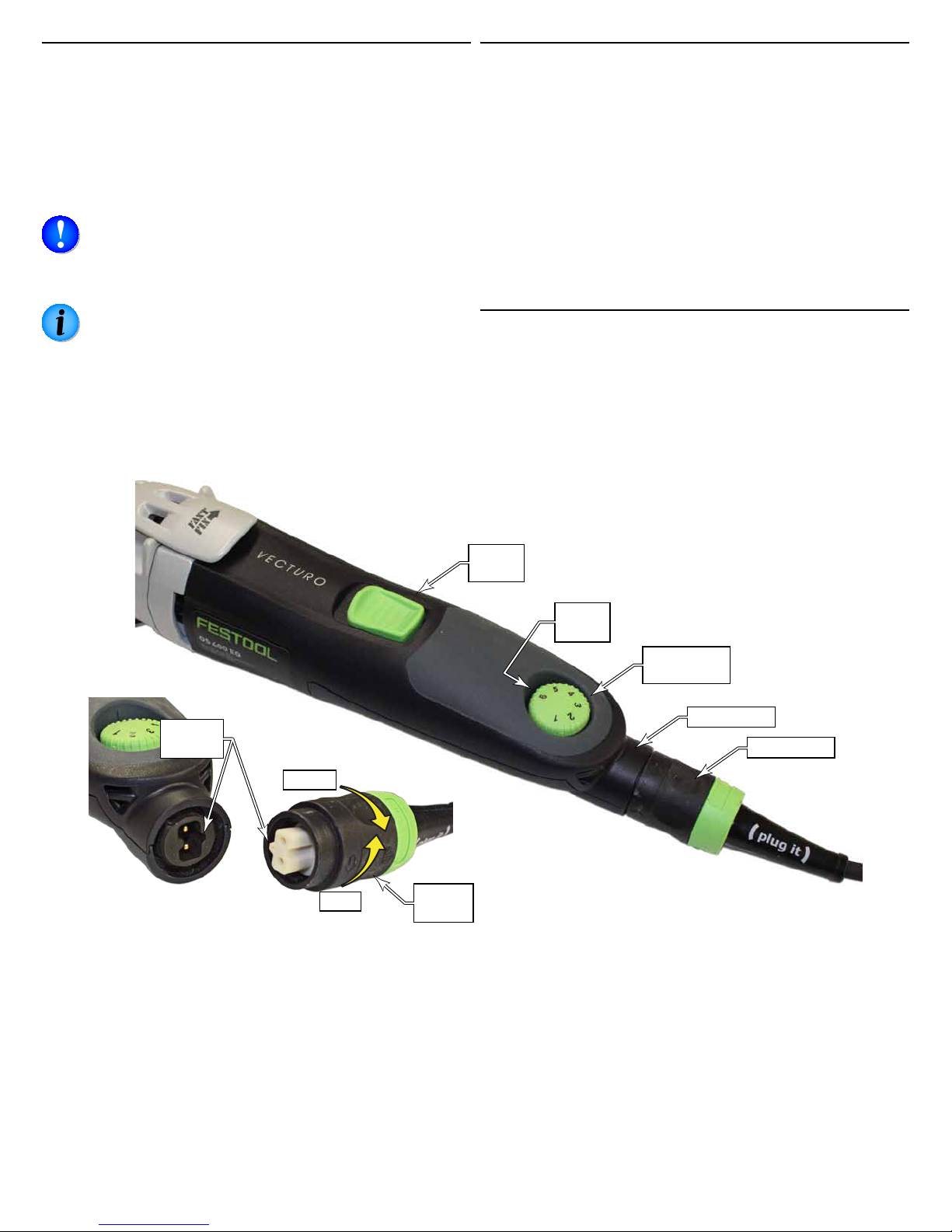
Connecting the Plug-It Power Cord
The Vecturo comes equipped with a removable Plug-It
power cord. The cord can be removed for easier storage of
the tool.
To install the power cord, insert the cord into the inlet (port)
on the tool with the key and keyway aligned, and twist the
locking ring ¼-turn until it clicks. Reverse the procedure to
remove the cord.
NOTICE: Make sure to fully tighten the plug-it cord
a full quarter-turn until it clicks. If the plug is not
fully locked, the socket and cord can overheat and be
damaged.
NOTE: The 18 gauge plug-it cord is interchangeable
with other tools that use the same size cord, but it
cannot be used with larger tools, such as routers and
saws. The plug has an extra key to prevent it from
being used on a larger tool that would otherwise
damage the cord. Larger cords may be used with
smaller tools, but not the reverse.
Setting the Speed Control
The Vecturo is variable speed controlled from 10,000 to
18,500 oscillations per minute. Different speeds are used for
different tasks, but the optimal speed is somewhat subject
and not rigidly dened. A lower speed results in less heat,
and is therefore preferred, but a higher speed results in
greater control and cleaner cuts. Generally speaking softer
materials may be cut with lower speeds. A good rule of
thumb is to use the lowest speed that performs the desired
task with good control.
The speed may be set with the motor running or not running. The higher the number on the speed control dial, the
higher the speed.
Power Switch
The power switch is self-latching, and will stay on until you
switch it off. Slide the switch forward to turn the tool on,
and slide the switch back to turn the tool off. Note that the
tool has a soft-start motor, so there is a slight delay from
turning it on to when the motor begins to run.
Key &
Keyway
Unlock
Lock
Power
Switch
Speed
Setting
Speed
Control Dial
Plug-It Port
Plug-It Cord
Locking
Ring
10 Vecturo OS 400 EQ Multi-Tool
Page 11

Operation
Cutting Blade Principles
Even though a multi-tool is fairly unique in its cutting operation from other saw types, at the blade teeth it still resembles a short-stroke reciprocating saw. The blade oscillates
through a 4° sweep at high speed. The cut is radial, but the
short 4° stroke has the effectiveness of a linear stroke.
As with a typical reciprocating saw, the cutting direction is
forward of the teeth, which represents a plunging cut in the
direction of the blade. Because the blade cannot cut laterally
on the non-thoothed edges, making a wider cut requires
successive partial plunge cuts or tilting the blade in the
lateral direction.
One of the primary operations of a multi-tool is ush trimming one workpiece relative to the surface of another. This
is why most blades have an offset in the main body, and the
blade itself is spot-welded to the offset plate. This provides
a at, smooth reference surface on the blade for controlling
the cut.
Flat Blade
Spot Welds
Mandrel
4° Sweep
Cutting
Direction
For linear cutting operations, the best method is to use a
semicircular blade. The blade can cut anywhere around the
circumference, including the forward edge for making a
linear cut.
Offset
Plate
For making a ush-trim cut, rest the tool/blade on the reference surface for guidance. In the example below, a scrap of
ooring is used to control the height of the cut for trimming
casing and moulding so that the nished ooring can be
installed under the mouldings.
Supplemental Owner’s Manual 11
Page 12
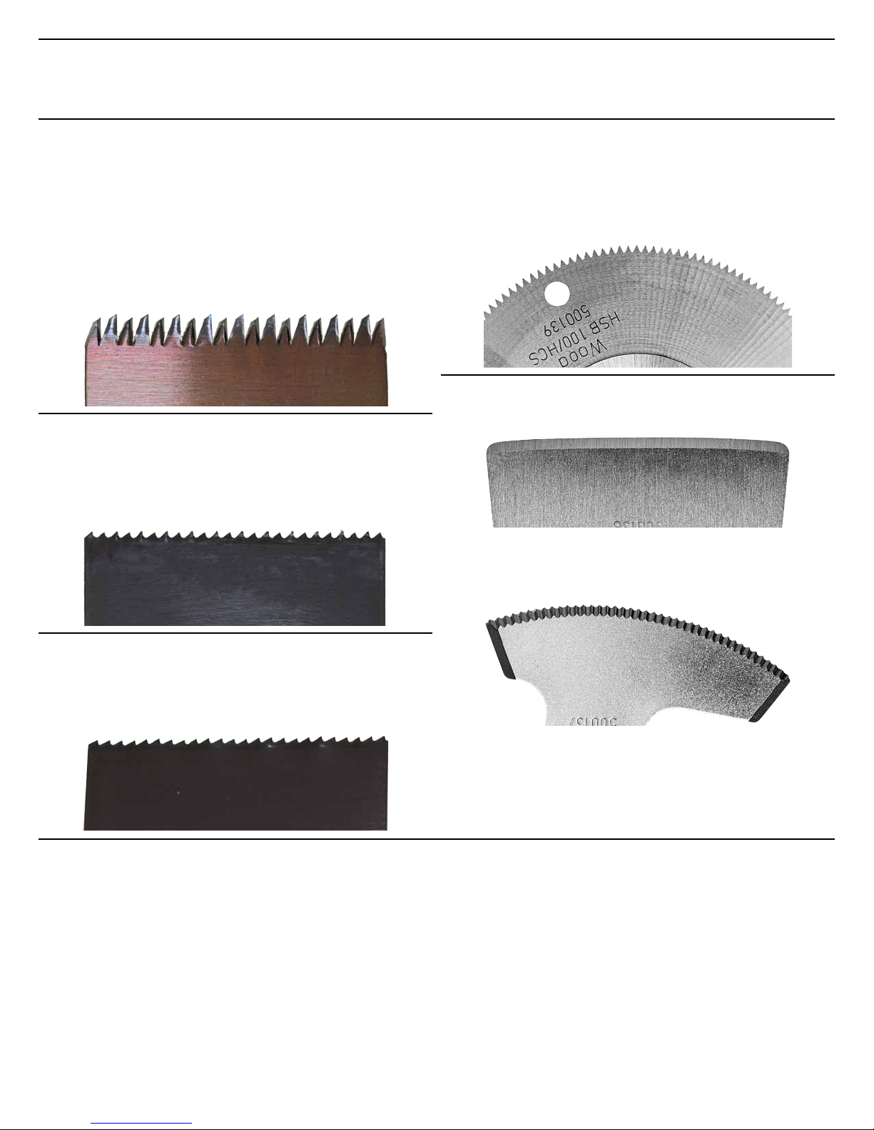
Cutting Blade Selection
A wide variety of cutting blades are available for the
Vecturo. Each blade has optimal performance for a variety
of applications.
One note about multi-tool blades is that by their nature and
the heat generated, they can become dull very quickly. So it
is always a good idea to have spare blades on hand.
Wood-Cutting, Japanese-Style Blades
The wood cutting blades have a Jananese-style tooth grind.
This is an internal grind without a set to the teeth. This
results in crisp cuts and minimum kerf thickness. However,
the features that give the Japanese-style teeth its high
performance aren’t without cost. Because there isn’t a set to
the teeth, the blade can be more prone to binding on deeper
cuts. The rapid cutting afforded by the longer teeth, can
also result in more frequent tooth loss. For these reasons,
the Jananese-style blades should not be used for making
conned plunge cuts using the plunge base.
Universal Wood/Composite Blades
These blades have a moderate hook angle to the grind and
an alternating tooth set. This provides for good cutting
speed and clean kerf for cutting woods and composites
without binding. (The bimetal teeth are hard enough to cut
through periodic nails, but not intended for cutting metal.)
Linear Cutting Circular Blades
The circular blades are ideal for making linear cuts because
they always present forward cutting teeth in all directions.
The triangular ground teeth permit cutting equally in either
feed direction. The teeth have no side-set for a clean cut,
but this doesn’t pose a signicant binding problem unless
the cut is signicantly deep.
Scraper Blades
The smooth scraper blade has a knife edge for cutting or
scraping softer materials such as soft adhesives or lms.
The serrated scraper blade can cut more aggressively
with either hard or soft adhesives and lms. Additionally,
the radially curved blade permits linear cutting as well as
plunging.
Metal Cutting Blades
The metal cutting blades have a higher tooth count, sharper
hook angle, and a wave tooth set. They are used for cutting
harder materials from hard plastics to light ferrous metals,
such as nails.
Cutting Speed Selection
There are various factors that determine which cutting
speed is ideal for the application. However, due to the
nature of the cutting tool, the optimal speed is more subjective than other tools. Here are some pointers:
► The short sweep (4°) and high vibratory speed results in
signicant heat buildup at the blade. To keep the heat to a
minimum, a good rule of thumb is to use the lowest speed
that still provides the desired cutting results.
► Conversely, in many cases, greater control of the cutting
blade is achieved with higher speeds. If the tool jumps or
is jittery, especially at the beginning of a cut, try increasing the speed. As the cut gets deeper, you may want to
reduce the speed to reduce the heat.
12 Vecturo OS 400 EQ Multi-Tool
► Softer materials can generally be cut with lower speeds,
but if the material tends to grab the blade, consider a
higher speed or even a ner-toothed blade.
► Typically, harder materials are best cut with a higher
speed, but the trade off is higher heat build up.
► Friable materials, such as drywall, can be cut with any
speed. So the deciding factor on speed is achieving the
best control.
► All other things being equal, lower speeds may be used
with the plunge base versus a freehand cut.
Page 13

Maintenance and Adjustment
WARNING! Any maintenance or repair work
that requires opening of the motor or gear housing should be carried out only by an authorized
Customer Service Center (see your dealer for
information on locating a service center).
WARNING! To reduce the risk of electrocution or
other personal injury, always unplug the tool from
the power supply outlet before performing any
maintenance or repair work on the tool.
Routine Maintenance
Aside from keeping the tool clean and in operating condi-
tion, the Vecturo does not require any specic routine
maintenance.
► Periodically inspect the arbor bore to ensure there is no
dust or debris buildup.
► Inspect the mandrel’s serrated shaft for damage or blunt-
ing of the serrations. These are what hold the mandrel
rmly in the tool.
NOTICE: Do not use compressed air to clean the
motor housing of the tool, as you could inject foreign objects into the motor through the ventilation
openings.
NOTICE: Certain cleaning agents and solvents are
harmful to plastic parts. Some of these include, but
are not limited to: Gasoline, Acetone, Methyl Ethyl
Ketone (MEK), Carbonyl Chloride, cleaning solutions
containing Chlorine, Ammonia, and household cleaners containing Ammonia.
Dust and debris from some materials can be extremely
abrasive and cause components within the tool to wear
prematurely. It is important to keep moving parts cleared of
abrasive dusts.
► As a general rule, keep the tool clean of all dust and
debris. Even soft-wood dust can be abrasive over time.
► Examine all moving parts for dust and debris.
Troubleshooting
Symptom Possible Causes
Motor does not start ► Check that the cord is properly plugged into an outlet.
► Make sure the Plug-it connector is properly inserted and fully tightened.
► Make sure the outlet has power. Check the circuit breaker or try another outlet.
► If used with a Festool dust extractor, make sure the selector switch is pointing to “Auto”. The
auxiliary outlet on the dust extractor has power only when the selector is at Auto.
► Inspect the power cord (including extension cords) for damage or missing prongs.
► The motor brushes may have worn and need replacement.
Tool runs sporadically
or looses power
Blades are loose
Blades dull or missing
teeth
► Make sure the Plug-it cord is properly tightened. Inspect the plug and tool power inlet for
signs of overheating. If signs of overheating are present, discontinue use and have the tool
serviced. If the Plug-it cord shows signs of overheating, do not use the cord for other tools,
as it can damage the inlet of the other tool.
► Verify that the blade was properly installed. Open the Fast-Fix lever, press in on the man-
drel, and then re-close the Fast-Fix lever.
► Make sure the arbor bore is clean and does not contain impacted dust and debris.
► Inspect the blade and mandrel to make sure the 12-point splines are not deformed.
► The arbor clutch disks may be worn and need service. Contact the Festool service center for
repair.
► It is normal for oscillating blades to wear quickly due to their nature and the amount of heat
generated. Deep or binding cuts generate more heat. When using wide blades, take care not
to tilt the tool and cause binding in the cut.
► If a tooth catches the workpiece just as the oscillation is reversing, the tooth can easily
break off. If it occurs frequently, try using a ner-toothed blade.
► Japanese-style blades are especially prone to breaking teeth, because the teeth are long,
thin, have no side-set, and very aggressive in their cutting. To reduce the frequency of
breaking teeth, take less aggressive cuts and avoid conned plunging, such as with the
plunge base.
Supplemental Owner’s Manual 13
Page 14

Motor Brush Replacement
Motor brushes provide electricity to the spinning motor
armature, and will wear over time. The copper strips on the
armature that the brushes connect to is called the com-
mutator, and these connect to the windings in the armature.
Because these electrical connections are constantly connected and disconnected as the motor turns, it is perfectly
normal for there to be sparks at the brushes during normal
use. The brushes are designed to disconnect power to the
motor when they have warn beyond their usable life. If your
Vecturo stops working, it is likely that the brushes have
warn and need replacement. Contact Festool for replacement brushes.
WARNING! To avoid the risk of electrical shock,
make sure the tool is unplugged from power.
1. Unplug the tool from power.
2. Using a T15 Torx driver, remove the 3 screws that secure
the brush cover to the main body. Two screws are selftapping and 1 is a machine screw.
3. Lift the brush cover off the main body, rst at the front
and then the rear (plug-it port). During reinstallation,
reverse this to engage the rear alignment tabs rst.
6. Lift the coil spring off the brush and rest it behind the
brass brush holder body to keep it in place. Take care to
not let the spring loose or uncoil.
NOTE: If the coil spring does come loose, it is ½ a
revolution to put it back in place.
7. Slide the brush out of the brush holder and insert the
new brush with the wire and terminal furthest from the
coil spring.
8. Move the coil spring back to pressing against the brush.
However, if you have difculty reinstalling the brush holders with the spring engaged, you may consider leaving
them loose until after the holders are in place.
Wire and
Terminal
Brush
Mounting
Screws
4. Using a tweezer or needle nose pliers, carefully remove
the motor and brush terminals from the brush holders.
5. Using a T15 Torx driver, loosen the brush holder mounting screw, and remove the brush holder with the screw
together. Note: As you lift the left brush holder out of the
motor, make note of how the blue wire is routed to the
side of the mounting screw, but below the brass holder.
Brush Terminals
Motor Terminals
Coil Spring Set
to the Side.
Alignment
Pin
Terminal
Spades
Brush
Holder Body
9. While compressing the brush into the holder, place the
holder into the motor housing, with the alignment pin in
the alignment hole. (See images above and below).
10. Tighten the mounting screws and reconnect the wire
terminals.
NOTE: The new brushes may spark more than
normal until they get seated and form to the shape of
the commutator. This should be expected.
Mounting Hole
Mounting Screws
Alignment Hole
Wire:
See Note
14 Vecturo OS 400 EQ Multi-Tool
Page 15

Notes
Supplemental Owner’s Manual 15
Page 16

Festool USA
400 N. Enterprise Blvd
Lebanon, IN 46052
www.festoolusa.com
Service Questions:
800-554-8741
Application Questions:
888-337-8600
 Loading...