

Page 1
Instruction manual
Page 6 - 16
IMPORTANT: Read and understand all instructions before
using.
Guide d’utilisation
Page 17 - 29
IMPORTANT: Lire et comprendre toutes les instructions
avant de démarrer les travaux.
Manual de instrucciones
Pagina 30 - 42
IMPORTANTE: Lea y comprende todas las instrucciones
antes de usar.
472601_003
Instruction manual
Guide d’utilisation
Manual de instrucciones
OF 2200 EB
Page 2

Page 3

Page 4
1.1
1.2
1.3
1.4
1.5
1.6
1.7
1.8
1.9
1.11
1.11
1.10
Page 5
2.5
2.1
2.2
2.3
2.4
Page 6

6
Table of contents
Safety rules 6
Technical data 8
Symbols 8
Functional description 8
Use for intended purpose 8
Electrical connection 8
Switching the machine on and off 8
Tool settings 9
Electronic control 9
Chips extraction 9
Milling cutters 10
Changing the clamping collet 11
Adjusting the milling depth 11
Preliminary/Fine routing 12
Fine adjuster for edge trimming 12
Working with the router 12
Machine guidance methods 13
Changing the base runner 14
Aluminium processing 15
Accessories, tools 15
Servicing and maintenance 15
Warranty 15
Safety rules
Read and understand all in-
structions. Failure to follow all instructions
listed below may result in electric shock, fi re
and/or serious personal injury.
2) Electrical safety
a) Power tool plugs must match the outlet. Never modify the plug in any way. Do
not use any adapter plugs with earthed
(grounded) power tools. Unmodifi ed plugs
and matching outlets will reduce risk of electric shock.
b) Avoid body contact with earthed or
grounded surfaces such as pipes, radiators, ranges and refrigerators. There is an
increased risk of electric shock if your body is
earthed or grounded.
c) Do not expose power tools to rain or
wet conditions. Water entering a power tool
will increase the risk of electric shock.
d) Do not abuse the cord. Never use the
cord for carrying, pulling or unplugging
the power tool. Keep cord away from
heat, oil, sharp edges or moving parts.
Damaged or entangled cords increase the risk
of electric shock.
e) When operating a power tool outdoors,
use an extension cord suitable for outdoor use. Use of a cord suitable for outdoor
use reduces the risk of electric shock.
f) Hold power tool by insulated gripping
surfaces only, when performing an operation where the cutting accessory may
contact hidden wiring or its own cord.
Contact with a „live“ wire will make exposed
metal parts of the power tool „live“ and shock
the operator.
SAVE THESE INSTRUCTIONS
General safety rules
1) Work area safety
a) Keep work area clean and well lit. Clut-
tered and dark areas invite accidents.
b) Do not operate power tools in explosive atmospheres, such as in the presence of fl ammable liquids, gases or dust.
Power tools create sparks which may ignite
the dust or fumes.
c) Keep children and bystanders away
while operating a power tool. Distractions
can cause you to lose control.
3) Personal safety
a) Stay alert, watch what you are doing
and use common sense when operating a
power tool. Do not use a power tool while
you are tired or under the infl uence of
drugs, alcohol or medication. A moment of
inattention while operating power tools may
result in serious personal injury.
b) Use safety equipment. Always wear
eye protection. Safety equipment such as
dust mask, non-skid safety shoes, hard hat,
or hearing protection used for appropriate
conditions will reduce personal injuries.
c) Avoid accidental starting. Ensure the
switch is in the off position before plugging in. Carrying power tools with your fi nger
on the switch or plugging in power tools that
have the switch on invites accidents.
Page 7

7
d) Remove any adjusting key or wrench
before turning the power tool on. A wrench
or a key left attached to a rotating part of the
power tool may result in personal injury.
e) Do not overreach. Keep proper footing and balance at all times. This enables
better control of the power tool in unexpected
situations.
f) Dress properly. Do not wear loose
clothing or jewellery. Keep your hair,
clothing and gloves away from moving
parts. Loose clothes, jewellery or long hair
can be caught in moving parts.
g) If devices are provided for the connection of dust extraction and collection
facilities, ensure these are connected
and properly used. Use of these devices
can reduce dust related hazards.
4) Tool use and care
a) Do not force the power tool. Use the
correct power tool for your application.
The correct power tool will do the job better
and safer at the rate for which it was designed.
b) Do not use the power tool if the switch
does not turn it on and off. Any power tool
that cannot be controlled with the switch is
dangerous and must be repaired.
g) Use the power tool, accessories and
tool bits etc., in accordance with these
instructions and in the manner intended
for the particular type of power tool, taking into account the working conditions
and the work to be performed. Use of
the power tool for operations different from
those intended could result in a hazardous
situation.
5) Service
a) Have your power tool serviced by a
qualifi ed repair person using only identi-
cal replacement parts. This will ensure that
the safety of the power tool is maintained.
Specifi c Safety Rules
a) Hold power tools by insulated gripping
surfaces when performing an operation
where the cutting tool may contact hidden wiring or its own cord. Contact with a
”live” wire will make exposed metal parts of
the tool ”live” and shock the operator.
b) Use clamps or another suitable means
to support and secure the workpiece to
a stable platform. Holding the workpiece
by hand or against your body is unstable and
may lead to loss of control.
c) Disconnect the plug from the power
source before making any adjustments,
changing accessories, or storing power
tools. Such preventive safety measures re-
duce the risk of starting the power tool accidentally.
d) Store idle power tools out of the reach
of children and do not allow persons
unfamiliar with the power tool or these
instructions to operate the power tool.
Power tools are dangerous in the hands of
untrained users.
e) Maintain power tools. Check for misalignment or binding of moving parts,
breakage of parts and any other condition that may affect the power tools operation. If damaged, have the power tool
repaired before use. Many accidents are
caused by poorly maintained power tools.
f) Keep cutting tools sharp and clean.
Properly maintained cutting tools with sharp
cutting edges are less likely to bind and are
easier to control.
Health hazard by dust
Various dust created by power
sanding, sawing, grinding, drilling and other
construction activities contains chemicals
known (to the State of California) to cause
cancer, birth defects or other reproductive
harm. Some examples of these chemicals
are:
•
Lead from lead-based paints,
Crystalline silica from bricks and cement
•
and other masonry products,
Arsenic and chromium from chemically-
•
treated lumber.
The risk from these exposures varies, depending on how often you do this type of work.
To reduce your exposure to these chem-
icals work in a well ventilated area and
use approved safety equipment, such as
dust masks that are specially designed
to fi lter out microscopic particles.
Page 8
8
TO REDUCE THE RISK OF
INJURY, USER MUST READ AND UNDERSTAND INSTRUCTION MANUAL.
Technical data
Power 15 A
Voltage ~ 120 V, 60 Hz
No load speed 10000 - 22000 rpm
Quick height adjustment 80 mm (3.1“)
Fine height adjustment 20 mm (0.8“)
Router diameter, max. 89 mm (3.5")
Drive shaft connection
of the spindle M 22x1
Weight 7.8 kg (17.2 lbs)
Protection class
/ II
Symbols
V Volts
A Amperes
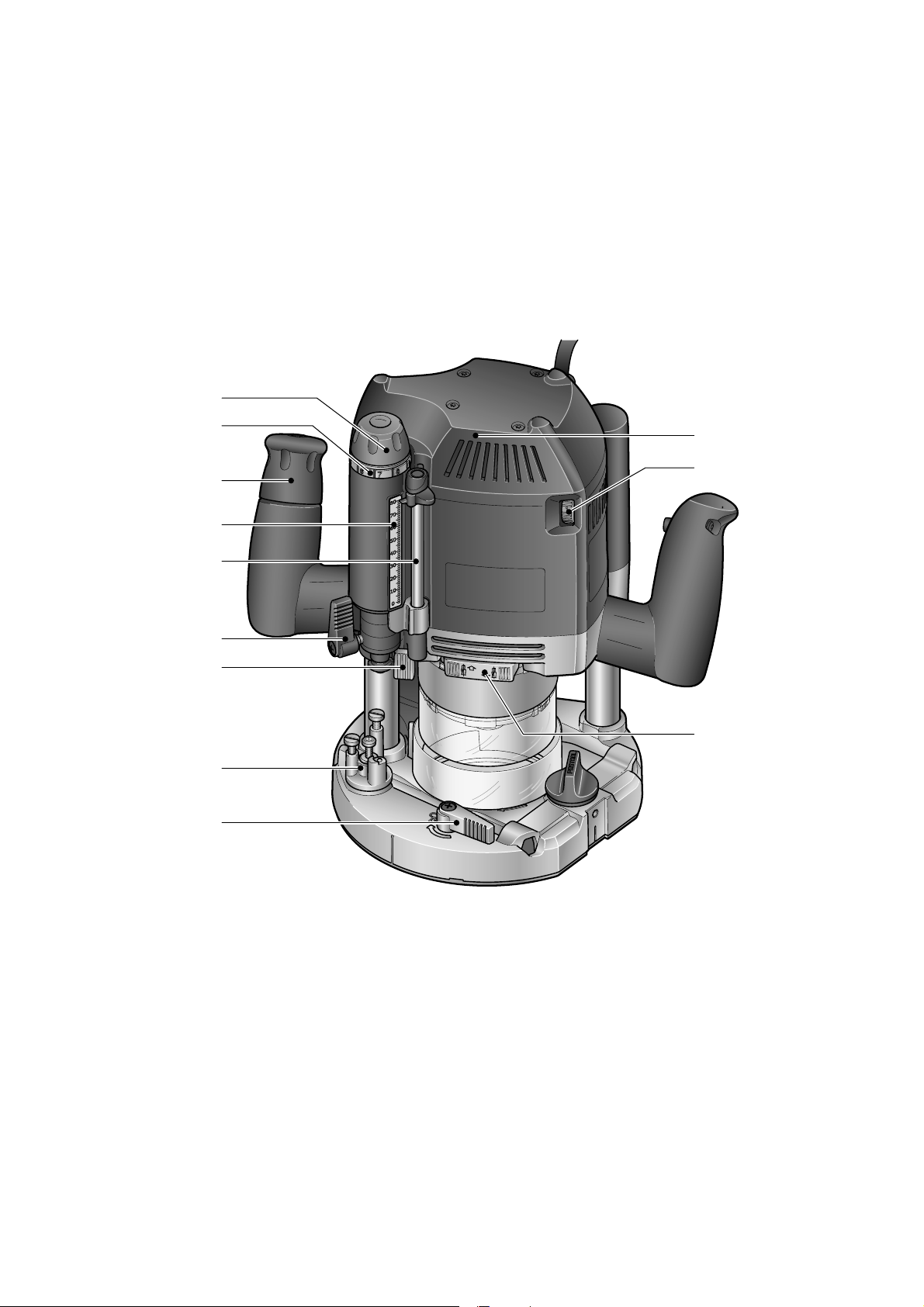
1.7 Eccenter for connecting depth stop
and stepped stop
1.8 Stepped stop
1.9 Lever for changing base runner
1.10 Rocker switch for spindle lock
1.11 Adjusting wheel for speed control
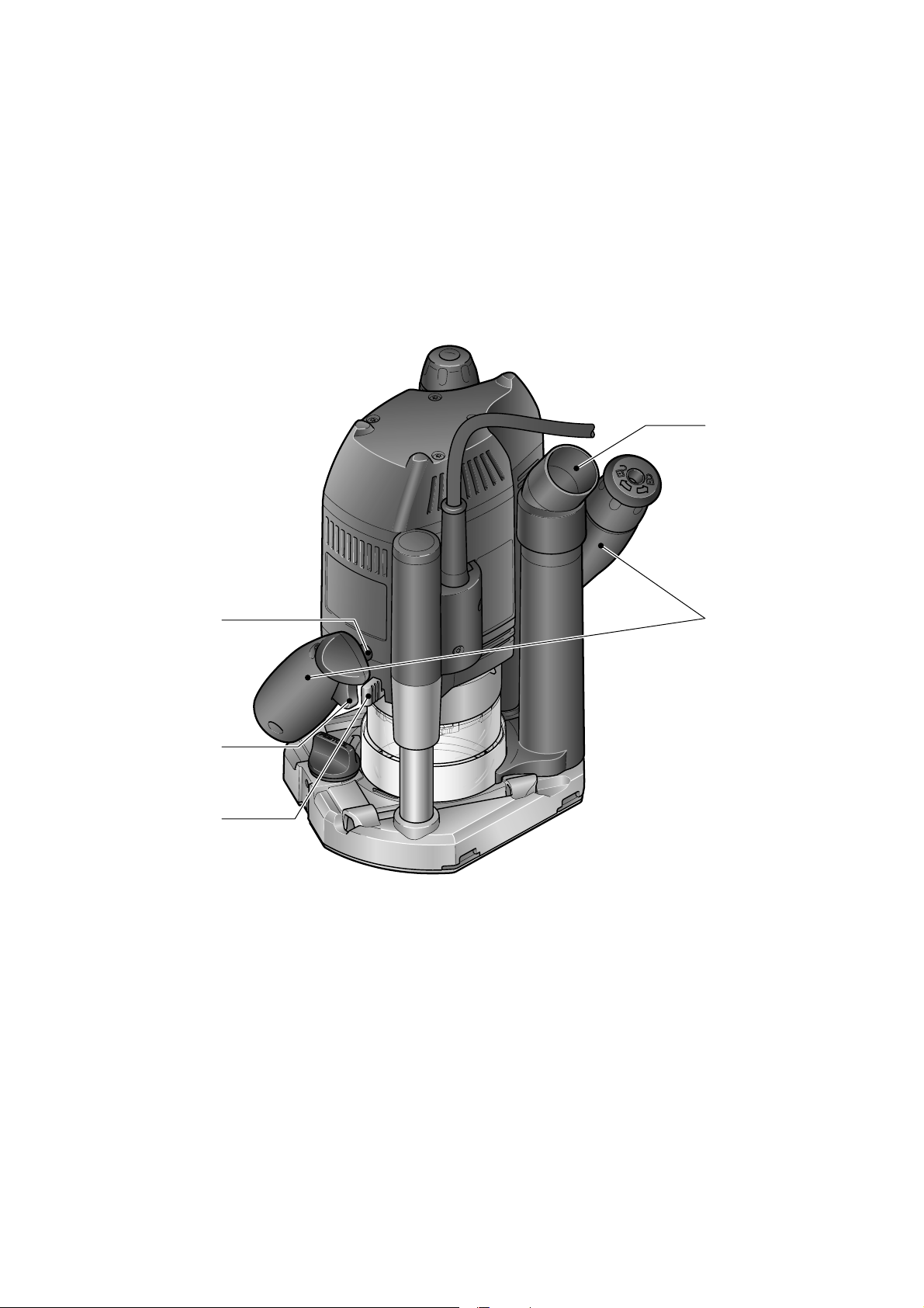
2.1 Locking knob for on/off switch
2.2 On/off switch
2.3 Lever for locking protective guard
2.4 Handles
2.5 Extractor connector
Use for intended purpose
The routers are designed for routing wood,
plastics and similar materials. Aluminium and
plasterboard can also be processed with corresponding cutters such as are listed in the
Festool catalogues.
The user is liable for damag-
es and injuries due to incorrect usage.
Hz Hertz
~ Alternating current
No load speed
n
0
Class II Construction
rpm Revolutions or reciprocation per
minute
Ø Diameter
Warning of general danger
Read the Operating Instructions/
Notes!
f Advice or tip
Functional description
The pictures for the functional description
are on a fold-out page at the beginning of
the instruction manual. When reading of the
manual you can fold out this page for having
always an overview of the machine.
1.1 Adjusting wheel for fi ne routing
depth adjustment
1.2 Dial ring for fi ne routing depth ad-
justment
1.3 Rotary knob for fi xing routing depth
1.4 Scale for routing depth
1.5 Depth stop with indicator
1.6 Clamp lever for depth stop
Electrical connection
The network voltage must conform to the
voltage indicated on the rating plate. A 16 A
safety fuse (for 120 V) or a corresponding
protective circuit-breaker is required.
Extension cable
If an extension cable is required, it must have
a suffi cient cross-section so as to prevent an
excessive drop in voltage or overheating. An
excessive drop in voltage reduces the output
and can lead to failure of the motor. The table
below shows you the correct cable diameter as
a function of the cable length for the router OF
2200 EB. Use only U.L. and CSA listed extension cables. Never use two extension cables
together. Instead, use one long one.
Total Extension Cord
Lenght (feed)
Cord size (AWG) 16 14 12 10
Note:
The lower the AWG number, the stronger the
cable.
25 50 100 150
Page 9
9
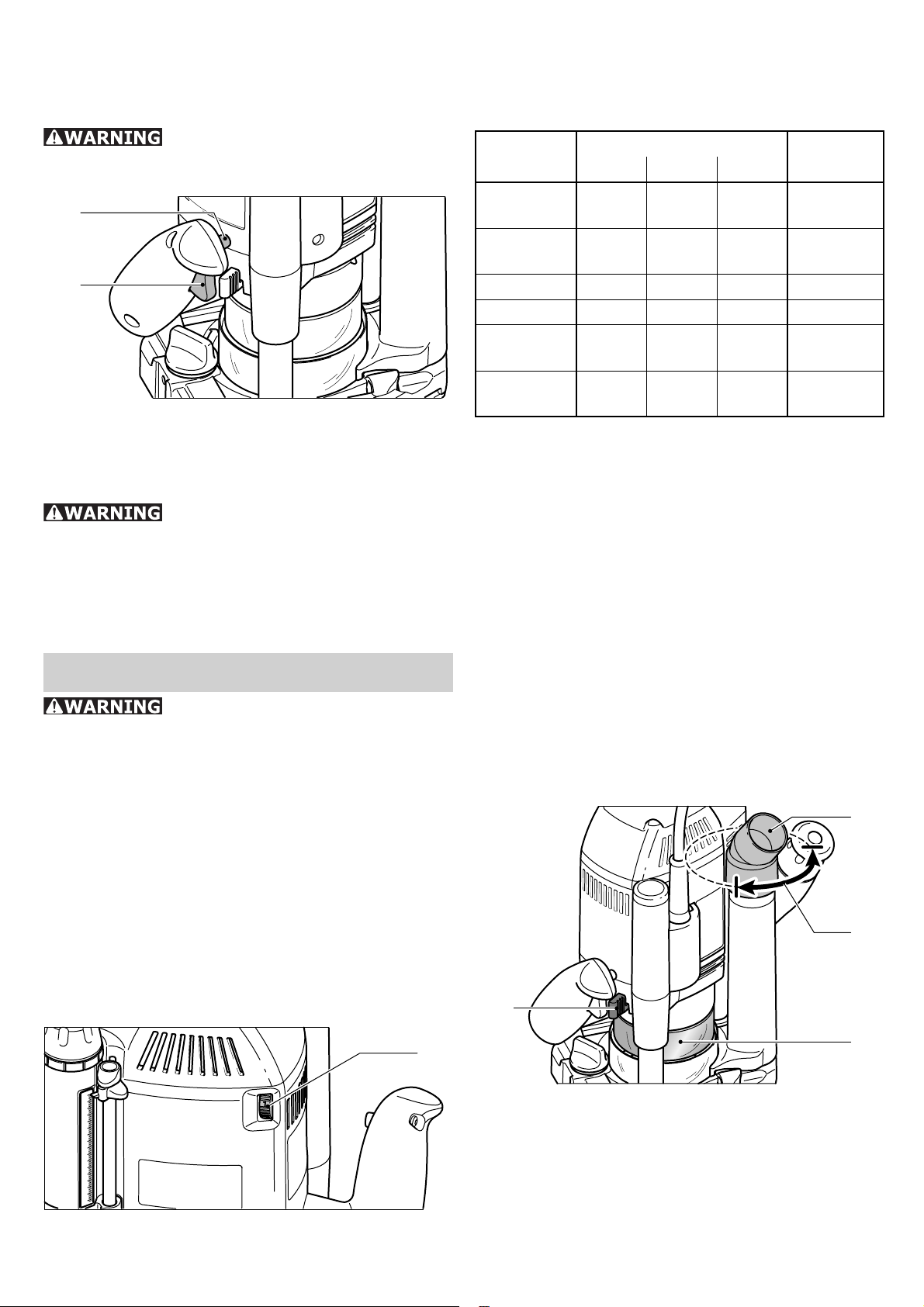
Switching the ma-
chine on and off
Keep the machine steady
during switching and during use by holding the handles with both hands.
3.1
3.2
The switch [3.2] is an on/off switch. Press the
side locking knob [3.1] to lock the switch for
continuous operation. Press the switch again
to release the knob.
After the machine has been
switched off, the milling cutter will still
rotate for a time. Take care that parts of
your body do not come into contact with the
milling cutter while it is still rotating!
the adjusting wheel [4.1]. This enables you to
optimise the cutting speed to suit the respective material and routing tool:
Material
Hard
wood
Soft wood 6-5 6-4 5-3 HSS
Panels 6-5 6-4 4-2 HW
Plastic 6-4 6-3 3-1 HW
Alumini-
um
Plaster-
board
Cutter diameter [mm] Cutter
10-30 30-50 50-89
material
6-4 5-3 3-1 HW
(HSS)
(HW)
3-1 3-1 2-1 HSS
(HW)
2-1 1 1 HW
Constant speed:
The selected motor speed is electronically
maintained to a constant level. By this means
a uniform cutting speed is achieved.
Brake
The OF 2200 EB has an electronic brake,
which stops the spindle within a few seconds
of the machine switching off.
Tool settings
Always disconnect the plug
from the power supply before making
any adjustments to the router or installing or removing any accessory!
Electronic control
The router OF 2200 EB has full-wave electronics with the following functions:
Smooth start-up:
The electronically controlled smooth start-up
function ensures that the machine starts up
smoothly.
Speed regulation:
6
9
8
7
80
70
60
50
40
30
20
10
0
4.1
Chips extraction
A Festool dust extractor with an extractor
hose diameter of 36 mm or 27 mm (36 mm
recommended due to the reduced risk of
clogging) can be connected to the extractor
connector [5.4].
5.4
5.3
5.1
5.2
The extractor connector [5.4] can be rotated
within the range indicated [5.3]. The extractor
connector on the extraction pipe will no longer
be secure if rotated outside of this range.
Chip guard
You can regulate the rotational speed steplessly between 10000 and 22000 rpm using
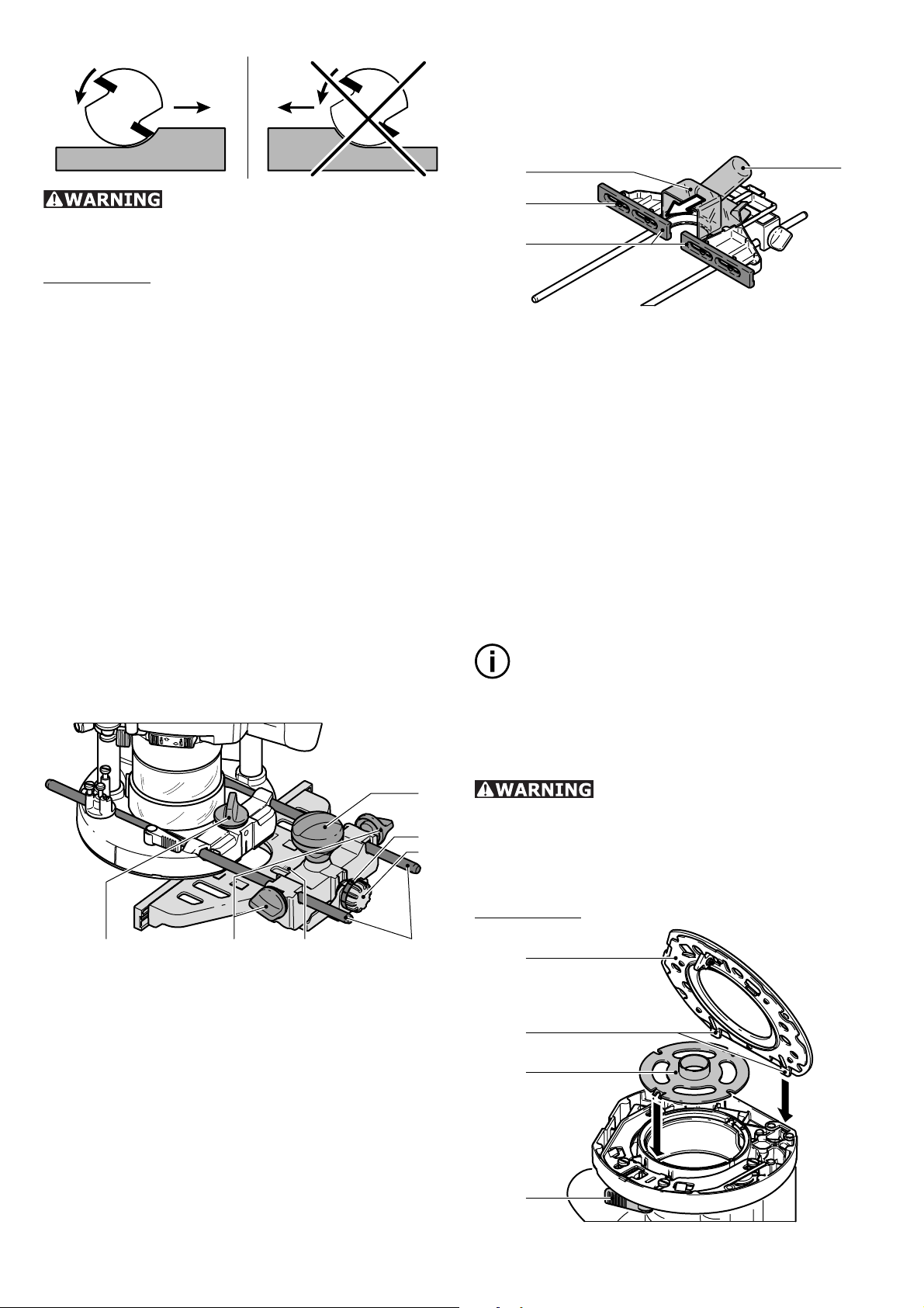
The chip guard [5.2] can be moved to the
top position to change the router bit, for ex-
Page 10
10
ample. Slide the chip guard upwards until it
engages or push the machine down as far as
possible.
We recommend lowering the chip guard before starting work to improve the effi ciency
of the extraction system. Push the lever [5.1]
towards the handle to do this.
KSF-OF chip defl ector
6.1
6.2
The chip defl ector KSF-OF [6.1] indirectly in-
creases the effi ciency of the extraction system
during edge routing. The maximum possible
routing diameter is 78 mm.
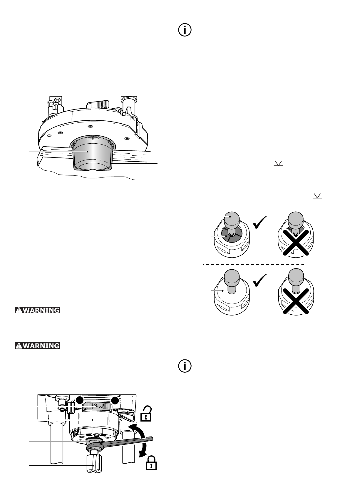
Note:
Switch off the machine before pressing the
f
rocker for the spindle lock [7.1]
a) Removing the tool
–
Slide the chip guard [7.2] upwards until it
engages, if necessary.
Press the rocker [7.1] for the spindle lock
–
to side A.
Unscrew the locking nut [7.3] using an
–
open-end wrench (size 24) until you are
able to remove the tool.
b) Inserting the tool
Insert the routing tool [7.4/7a.1] into the
–
open clamping collet as far as possible, but
at least up to the mark
on the shank
[7a.2]. If the collet is not visible because
it is blocked by the union nut [7a.3], the
milling tool must be insertes into the collet
at least far enough that the marker no
longer overlaps with the union nut.
7a.1
The defl ector is fi tted in a similar way to the
copying ring (see "Copy routing").
The hood can be cut off along the grooves
[6.2] using a hacksaw and can thus be reduced in size. The chip defl ector can then be
used for interior radiuses up to a minimum
radius of 52 mm.
Milling cutters
Do not exceed the maximum
speed specifi ed on the tool and/or keep
to the speed range. Cracked or distorted
cutters must not be used.
The routing tool may be hot
after use and has sharp edges. Allow the
tool to cool before changing. Wear protective
gloves when changing tools.
We recommend turning the machine on its
f
side to change the tool.
7.1
B
7.2
A
7a.2
7a.3
Press the rocker [7.1] for the spindle lock
–
to side B.
Tighten the locking nut [7.3] using an open-
–
end wrench (size 24).
Note:
The rocker only blocks the motor spindle in
f
one direction of rotation at any one time.
Therefore when the locking nut is undone
or tightened, the wrench does not need to
be offset but can be moved back and forth
like a ratchet.
7.3
7.4
Page 11
Changing the clamping collet
A
8.1
8.2
8.4
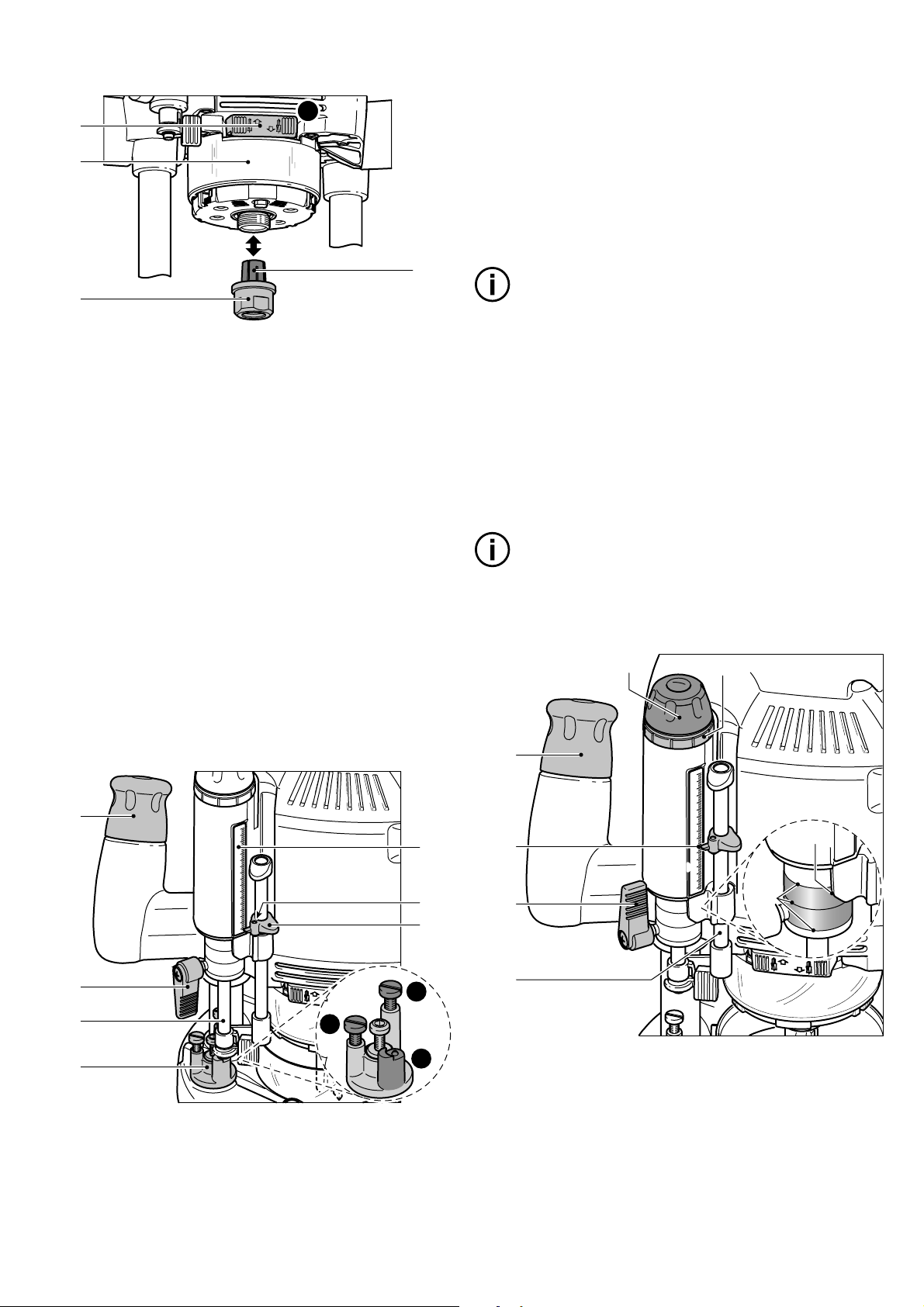
–
Push the machine downwards until the
router bit rests on the surface (reference
surface). Clamp the machine in this position
by tightening the rotary knob [9.1].
–
Press the depth stop [9.3] against one of
the three fi xed stops on the rotary stepped
stop [9.4].
–
Slide the indicator [9.5] down to the 0 mm
mark on the scale [9.7].
11
8.3
If necessary, slide the chip guard [8.2]
–
upwards until it engages.
Press the rocker [8.1] for the spindle lock
–
to side A.
Unscrew the locking nut [8.3] completely.
–
Remove the locking nut from the spindle
–
together with the clamping collet [8.4]. Do
not separate the locking nut and clamping
collet as these form a single component.
Attach a new clamping collet with locking
–
nut to the spindle.
Screw on the locking nut loosely. Do not
–
tighten the locking nut until a router bit is
inserted.Adjusting the milling depth
Adjusting the milling depth
The milling depth is adjusted in two steps:
a) Setting the zero point
6
9.1
9
8
7
80
70
60
50
40
30
20
10
0
9.7
9.6
9.5
Note:
f
If the base position of the indicator is incorrect, this can be adjusted by turning the
screw [9.6] on the indicator.
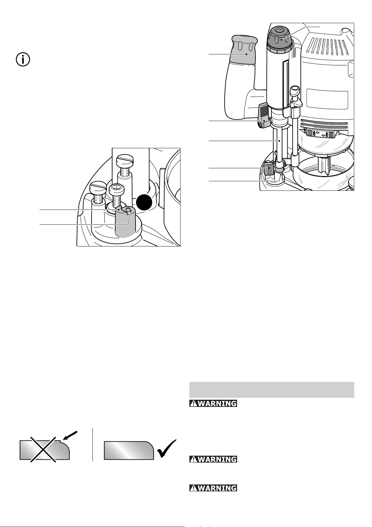
The stepped stop [9.4] has three stops, two
of which can be adjusted in height using a
screwdriver:
•
Stop A: 18 mm - 51 mm
•
Stop B: 6 mm - 18 mm
•
Stop C: 0 mm
Note:
f
Stop C has an offset for preliminary routing
- see "Preliminary/Fine routing".
b) Presetting the routing depth
10.6
6
10.1
10.2
10.3
10.5
9
8
7
80
70
60
50
40
30
20
10
0
10.7
10.8
9.2
9.3
9.4
Place the router on an even surface (refer-
–
B
ence surface).
Open the clamping lever [9.2].
–
Unscrew the rotary knob [9.1].
–
A
C
10.4
–
Pull the depth stop [10.4] upwards until
the indicator [10.2] reaches the required
routing depth.
–
Clamp the depth stop in this position using
the clamp lever [10.3].
–
Unscrew the rotary knob [10.1]. The machine is now in starting position.
–
If necessary, you can readjust the routing depth by turning the adjusting wheel
Page 12
12
[10.4]. Each mark represents a routing
depth of 0.1 mm. One complete turn of the
wheel is 1 mm.
Notes:
The dial ring [10.5] can be turned sepa-
f
rately to the "zero" setting.
The three marks [10.7] indicate the maxi-
f
mum adjustment range of the adjusting
wheel (20 mm) and the central position
when aligned with the edge [10.8].
Preliminary/Fine routing
11.1
11.2
Stop C has two stop limits with a height difference of 2 mm. Routing to the depth preset
with stop C can be performed in two steps:
–
Lower the router to the fi rst stop level
[11.1] for the preliminary routing step;
–
Lower the router to the second stop level
[11.2] to complete the routing procedure.
This procedure enables rapid routing to a
considerable depth while still achieving a good
surface quality. The fi nal routing depth is de-
fi ned by adjusting the stop level [11.2].
C
Fine adjuster for
13.6
13.1
13.2
13.3
13.4
13.5
Open the clamping lever [13.2].
–
Push the depth stop [13.3] against the fi xed
–
6
9
8
7
80
70
60
50
40
30
20
10
0
stop C [13.5].
Clamp the depth stop using the eccenter
–
[13.4] on the stepped stop (turn clockwise).
Close the clamping lever [13.2].
–
Unscrew the rotary knob [13.1].
–
–
Turn the adjusting wheel [13.6] to set the
routing depth more precisely.
f
The routing depth can be adjusted in both
directions because the depth stop is connected to the stepped stop.
Tighten the rotary knob [13.1].
–
Open the eccenter [13.4] (turn anticlock-
–
wise).
Perform more test runs and make the ap-
–
propriate adjustments if necessary.
edge trimming
The machine has a special fi ne adjuster for
routing tools with a bearing guide, which allows quick and easy precision adjustment prior
to rounding edges and prevents offsets.
First of all, roughly preset the routing depth
and perform a test run. Then adjust the routing depth more precisely:
Working with the router
Always ensure that your
workpieces are securely fi xed and can-
not move during routing. Otherwise, there
is an increased risk of accident. Use screw
clamps or some other suitable devices to fi x
your workpiece.
The machine must always be
held with both hands by the designated
handles.
Always switch the router on
fi rst before bringing the tool into contact
with the workpiece!
Page 13
millimetre scale [15.3] on the main casing
is useful for making larger adjustments.
Tighten the rotary knob [15.7] again after
–
completing any fi ne adjustments.
13
Always advance the router in
the same direction as the cutting direction of the cutter (counter-routing)!
Procedure:
–
Preset the required routing depth.
Switch on the machine.
–
Unscrew the rotary knob [13.1].
–
Push the machine down as far as pos-
–
sible.
Clamp the machine in this position by tight-
–
ening the rotary knob [13.1].
Perform the routing task.
–
Unscrew the rotary knob [13.1].
–
Move the machine slowly upwards to the
–
stop.
Switch off the machine.
–
Machine guidance methods
16.1
16.2
16.3
Adjust both guidance jaws [16.3] so that
–
16.4
they are approx. 5 mm from the router bit.
To do this, undo screws [16.2] and tighten
again after completing the adjustments.
Only when routing along an edge: slide
–
the extractor hood [16.1] until it latches
into position on the side stop and connect
an extraction hose 27 mm or 36 mm in
diameter to the extractor connector [16.4].
Alternatively, leave the machine to extract
the dust via the extractor connector.
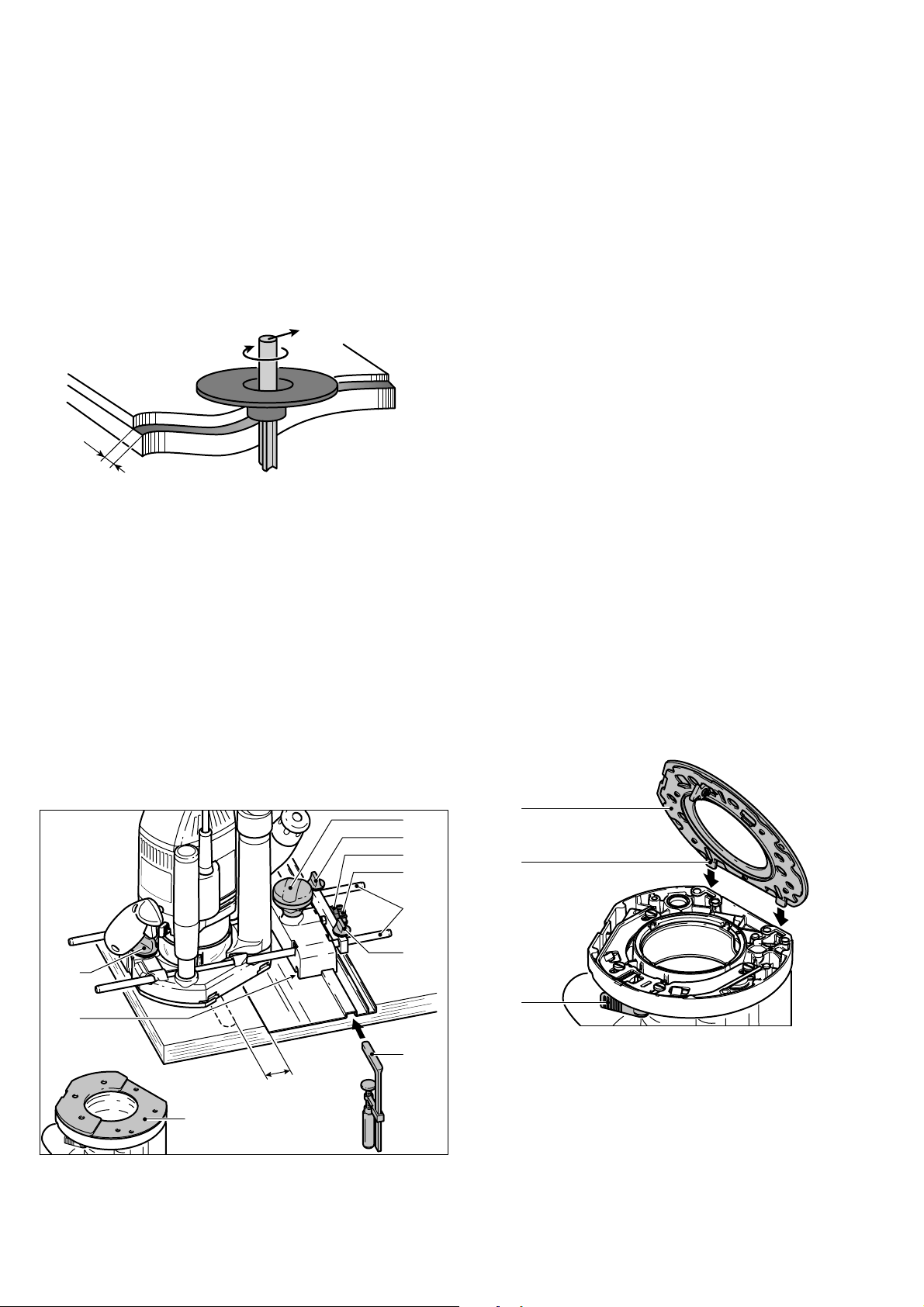
b) Copy routing
When routing with templates, fi t an integrated
copying ring to the router (accessory).
a) Routing with side stop
The side stop (partly as an accessory) is positioned parallel to the workpiece edge.
15.7
15.6
15.5
15.415.1 15.2 15.3
Secure both guide rods [15.4] with the two
–
rotary knobs [15.2] on the side stop.
Insert the guide rods into the grooves on
–
the router base to the required distance
and secure them by turning the rotary knob
[15.1].
Note:
Copying rings can be used in combination
f
with the standard base runner. A special
base runner is available as an accessory to
improve the contact surface.
An excessively large routing
tool may damage the copying ring and
cause accidents. Make sure that the routing
tool used fi ts through the opening on the
copying ring.
Procedure:
17.1
17.2
17.3
Fine adjustment
Unscrew the rotary knob [15.7] to make
–
fi ne adjustments with the adjusting wheel
[15.5]. The dial ring [15.6] has a 0.1 mm
scale for this purpose. If the adjusting
wheel is held secure, the dial ring can be
turned separately and set to "Zero". The
17.4
Lay the machine on its side on a stable
–
base.
Page 14
14
–
Open the lever [17.4].
–
Remove the base runner [17.1].
–
Release the lever [17.4] again.
–
Insert a copying ring [17.3] in the correct
position on the router base.
–
Insert the tabs [17.2] on a base runner into
the router base.
–
Push down the base runner until it engages
in the router base.
The overhang Y of the workpiece in relation
the template is calculated as follows:
Y
Y = ½ (diameter of copying ring minus
diameter of routing bit)
c) Edge trimming
Routing tools with a bearing guide are required
when the machine is used for edge trimming.
The machine is then guided in such a way that
the bearing guide rolls off the workpiece.
When trimming edges, always use the chip
defl ector KSF-OF to improve dust extrac-
tion.
d) Routing with a guide system FS
This base runner is offset to compensate
f
for the height of the guide rail.
Secure both guide rods [19.6] with the
–
rotary knobs [19.5] and [19.9] on the
guide stop.
Unscrew the rotary knob [19.1].
–
Insert the guide rods [19.6] into the
–
grooves on the router base.
Place the router with the guide stop on the
–
guide rail.
If required, you can adjust the play of the
–
guide stop on the guide rail by adjusting
the two guidance jaws [19.2] with a
screwdriver.
Slide the router along the guide rods until
–
the routing tool reaches the required
distance X from the guide rail.
Screw up the rotary knob [19.1].
–
Unscrew the rotary knob [19.10].
–
Turn the adjusting wheel [19.7] to adjust
–
distance X more precisely.
Hold the adjusting wheel [19.7] to turn the
f
scale [19.8] independently to "zero".
Screw up the rotary knob [19.10].
–
Changing the base runner
Festool offers special base runners (as an
accessory) for different applications.
Change the base runner as follows:
The guide system (partly as an accessory)
makes it easier to route straight grooves.
19.10
19.9
19.8
19.7
19.6
19.5
19.1
19.2
X
19.3
–
Secure the guide rail to the workpiece using
19.4
clamps [19.4].
–
Insert the base runner [19.3] for the guide
stop into the router base (see "Changing
the base runner").
20.1
20.2
20.3
Lay the machine on its side on a stable
–
base.
Open the lever [20.3].
–
Remove the base runner [20.1].
–
Release the lever [20.3] again.
–
Insert the tabs [20.2] on a base runner into
–
the router base.
Push down the base runner until it engages
–
in the router base.
Page 15

Aluminium processing
The following precautions
are to be taken when processing aluminium for safety reasons:
Pre-connect a residual current circuit-
•
breaker.
Connect the machine to a suitable dust
•
extractor.
Clean tool regularly of dust accumulations
•
in the motor housing.
Wear protective goggles.
•
Accessories, tools
For safety reasons, only use
original Festool accessories and tools!
Festool offers you a comprehensive range of
accessories for your router:
•
Routing tools for different applications.
•
Guide rails for straight routing.
•
Runner bases for different applications.
The accessory and tool order number can be
found in the Festool catalogue or on the Internet under www.festool-usa.com.
15
Snap all four latches back to their fl at po-
–
sition (21.3) so they engage the stacking
tabs of the upper systainer.
Servicing and
maintenance
Any maintenance or repair
work that requires opening of the motor
or gear housing should only be carried
out by an authorised Customer Service
Centre (name supplied by your dealer)!
Maintenance or repair work carried out by an
unauthorised person can lead to the wrong
connection of the power leads or other components, which in turn can lead to accidents
with serious consequences.
To prevent accidents, always
remove the plug from the power supply
socket before carrying out any maintenance or repair work on the machine! Do
not use compressed air to clean the electrical tool! Do not try to clean parts inside the
machine in this way, as you could let foreign
objects in through the openings of the machine housing.
Systainer
Many Festool products are shipped in a unique
system container, called "Systainer". This provides protection and storage for the tool and
accessories. The Systainers are stackable and
can be interlocked together. They also can be
interlocked atop Festool CT dust extractors.
21.3
21.2
21.1
–
Place one systainer on top of the other.
–
Release all four latches on the lower systainer by pulling back at their top edges
(21.1).
–
Slide all four latches upward (21.2).
Certain cleaning agents and
solvents are harmful to plastic parts.
Some of these are: gasoline, carbonyl chloride, cleaning solutions containing chlorine,
ammonia and household cleaners containing
ammonia.
•
To assure the circulation of air, the cool air
vents in the motor housing must always be
kept clear and clean.
•
This unit is fi tted with special, automati-
cally disconnecting carbon brushes. If these
become worn, the current is automatically
switched off and the unit shuts down. In
this case, take the unit to an authorised
Customer Service Centre and have the
carbon brushes changed.
Warranty
Conditions of 1+2 Warranty
You are entitled to a free extended warranty
(1 year + 2 years = 3 years) for your Festool
power tool. Festool shall be responsible for
all shipping costs during the fi rst year of the
warranty. During the second and third year of
Page 16

16
the warranty the customer is responsible for
shipping the tool to Festool. Festool will pay
for return shipping to the customer using UPS
Ground Service. All warranty service is valid
3 years from the date of purchase on your
receipt or invoice.
Festool Limited Warranty
This warranty is valid on the pre-condition that
the tool is used and operated in compliance
with the Festool operating instructions. Festool warrants, only to the original consumer
purchaser, that the specifi ed tool will be free
from defects in materials and workmanship
for a term of one year from the date of procurement. Festool makes no other warranty,
express or implied, for Festool portable power
tools. No agent, representative, distributor,
dealer or employee of Festool has the authority to increase or otherwise change the
obligations or limitations of this warranty. The
obligations of Festool in its sole discretion under this warranty shall be limited to the repair
or replacement of any Festool portable power
tool that is found to be defective as packaged
with the User Manual.
Excluded from coverage under this warranty
are: normal wear and tear; damages caused
by misuse, abuse or neglect; damage caused
by anything other than defects in material and
workmanship. This warranty does not apply to
accessory items such as circular saw blades,
drill bits, router bits, jigsaw blades, sanding
belts, and grinding wheels. Also excluded
are “wearing parts”, such as carbon brushes,
lamellas of air tools, rubber collars and seals,
sanding discs and pads, and batteries.
Festool portable power tools requiring replacement or repair are to be returned with the
receipt of purchase to Festool (call 800-5548741 for address details).
IN NO EVENT SHALL FESTOOL BE LIABLE
FOR ANY CONSEQUENTIAL OR INCIDENTAL DAMAGES FOR BREACH OF THIS OR
ANY OTHER WARRANTY, EXPRESSED OR
IMPLIED WHATSOEVER. ALL WARRANTIES IMPLIED BY STATE LAW, INCLUDING THE IMPLIED WARRANTIES OF
MERCHANTABILITY AND FITNESS FOR
A PARTICULAR PURPOSE, ARE HEREBY
LIMITED TO THE DURATION OF THREE
YEARS.
Some states in the U.S. and some Canadian
provinces do not allow the limitations on
how long an implied warranty lasts, so the
above limitation may not apply to you. With
the exception of any warranties implied by
state or province law as hereby limited, the
foregoing express limited warranty is exclusive
and in lieu of all other warranties, guarantees,
agreements and similar obligations of
Festool.
This warranty gives you specifi c legal rights
and you may also have other rights which vary
from state to state in the U.S. and province
to province in Canada.
Page 17

17
Sommaire
Régles de sécurité 17
Caractéristiques techniques 19
Symboles 19
Composants de l'outil 19
Utilisation conforme à l'emploi
prévu 20
Connexion électrique 20
Mise en marche et arrêt de la machine 20
Réglages de l'outil 20
Commande électronique 21
Aspiration des copeaux 21
Fraises 22
Changement du mandrin de serrage 22
Réglage de la profondeur de fraisage 23
Fraisage préliminaire / fi n 24
Dispositif de réglage fi n pour fraisage de
chants 24
Travail avec la fraiseuse 24
Méthodes de guidage de la machine 25
Changement du galet palpeur 27
Usinage de l'aluminium 27
Accessoires, outils 27
Entretien courant et maintenance 28
Garantie 28
Régles de sécurité
Assurez-vous de lire
et de bien com prendre toutes les instructions. Le non-respect, même partiel,
des instructions ci-dessous peut entraîner un
risque de choc électrique, d’incendie et/ou de
blessures graves.
CONSERVEZ CES INSTRUCTIONS
Régles de sécu-
rité générales
risquant d’enfl ammer les poussières ou les
vapeurs.
c) Tenez les enfants et autres personnes
éloignés durant l’utilisation de l’outil
électroportatif. En cas d’inattention vous
risquez de perdre le contrôle sur l’appareil.
2) Sécurité électrique
a) La fi che de secteur de l’outil électro-
portatif doit être appropriée à la prise
de courant. Ne modifi ez en aucun cas la
fi che. N’utilisez pas de fi ches d’adapta-
teur avec des appareils avec mise à la
terre. Les fi ches non modifi ées et les prises
de courant appropriées réduisent le risque de
choc électrique.
b) Evitez le contact physique avec des
surfaces mises à la terre tels que tuyaux,
radiateurs, fours et réfrigérateurs. Il y a
un risque élevé de choc électrique au cas où
votre corps serait relié à la terre.
c) N’exposez pas l’outil électroportatif
à la pluie ou à l’humidité. La pénétration
d’eau dans un outil électroportatif augmente
le risque d’un choc électrique.
d) N’utilisez pas le câble à d’autres fi ns
que celles prévues, n’utilisez pas le câble
pour porter l’appareil ou pour l’accrocher ou encore pour le débrancher de
la prise de courant. Maintenez le câble
éloigné des sources de chaleur, des parties grasses, des bords tranchants ou des
parties de l’appareil en rotation. Un câble
endommagé ou torsadé augmente le risque
d’un choc électrique.
e) Au cas où vous utiliseriez l’outil électroportatif à l’extérieur, utilisez une
rallonge autorisée homologuée pour les
applications extérieures. L’utilisation d’une
rallonge électrique homologuée pour les applications extérieures réduit le risque d’un
choc électrique.
1) Sécurité de aire de travail
a) Maintenez l’endroit de travail propre et
bien éclairé. Un lieu de travail en désordre ou
mal éclairé augmente le risque d’accidents.
b) N’utilisez pas l’appareil dans un environnement présentant des risques d’explosion et où se trouvent des liquides,
des gaz ou poussières infl ammables. Les
outils électroportatifs génèrent des étincelles
f) Ne tenez l‘outil qu‘à l‘aide des poignées
isolées, lorsque vous êtes susceptibles
de toucher des lignes électriques cachées ou votre propre câble électrique,
lorsque vous travaillez avec des outils de
tronçonnage. Si des outils de tronçonnage
touchent des lignes électriques, des pièces
métalliques de l‘outil peuvent être mises sous
tension et asséner une décharge électrique à
l‘utilisateur.
Page 18

18
3) Sécurité des personnes
a) Restez vigilant, surveillez ce que vous
faites. Faites preuve de bon en utilisant
l’outil électroportatif. N’utilisez pas l’appareil lorsque vous êtes fatigué ou après
avoir consommé de l’alcool, des drogues ou avoir pris des médicaments. Un
moment d’inattention lors de l’utilisation de
l’appareil peut entraîner de graves blessures
sur les personnes.
b) Portez des équipements de protection.
Portez toujours des lunettes de protection. Le fait de porter des équipements de
protection personnels tels que masque antipoussières, chaussures de sécurité antidérapantes, casque de protection ou protection
acoustique suivant le travail à effectuer, réduit
le risque de blessures.
c) Evitez une mise en service par mégarde. Assurez-vous que l’interrupteur est
effectivement en position d’arrêt avant
de retirer la fi che de la prise de courant.
Le fait de porter l’appareil avec le doigt sur
l’interrupteur ou de brancher l’appareil sur la
source de courant lorsque l’interrupteur est
en position de fonctionnement, peut entraîner
des accidents.
d) Enlevez tout outil de réglage ou toute
clé avant de mettre l’appareil en fonctionnement. Une clé ou un outil se trouvant
sur une partie en rotation peut causer des
blessures.
e) Ne surestimez pas vos capacités.
Veillez à garder toujours une position
stable et équilibrée. Ceci vous permet de
mieux contrôler l’appareil dans des situations
inattendues.
f) Portez des vêtements appropriés. Ne
portez pas de vêtements amples ni de
bijoux. Maintenez cheveux, vêtements et
gants éloignés des parties de l’appareil
en rotation. Des vêtements amples, des
bijoux ou des cheveux longs peuvent être
happés par des pièces en mouvement.
g) Si des dispositifs servant à aspirer
ou à recueillir les poussières doivent
être utilisés, vérifi ez que ceux-ci soient
effectivement raccordés et qu’ils sont
correctement utilisés. L’utilisation de tels
dispositifs réduit les dangers dus aux poussières.
4) Utilisation et entretien des outils
a) Ne surchargez pas l’appareil. Utilisez
l’outil électroportatif approprié au travail à effectuer. Avec l’outil électroportatif
approprié, vous travaillerez mieux et avec
plus de sécurité à la vitesse pour laquelle il
est prévu.
b) N’utilisez pas un outil électroportatif
dont l’interrupteur est défectueux. Un
outil électroportatif qui ne peut plus être mis
en ou hors fonctionnement est dangereux et
doit être réparé.
c) Retirer la fi che de la prise de courant
avant d’effectuer des réglages sur l’appareil, de changer les accessoires, ou de
ranger l’appareil. Cette mesure de précau-
tion empêche une mise en fonctionnement
par mégarde.
d) Gardez les outils électroportatifs non
utilisés hors de portée des enfants. Ne
permettez pas l’utilisation de l’appareil
à des personnes qui ne se sont pas familiarisées avec celui-ci ou qui n’ont pas lu
ces instructions. Les outils électroportatifs
sont dangereux lorsqu’ils sont utilisés par des
personnes non initiées.
e) Prenez soin des outils électroportatifs.
Vérifi ez que les parties en mouvement
fonctionnent correctement et qu’elles ne
soient pas coincées, et contrôlez si des
parties sont cassées ou endommagées
de telle sorte que le bon fonctionnement
de l’appareil s’en trouve entravé. Faites
réparer les parties endommagées avant
d’utiliser l’appareil. De nombreux accidents
sont dus à des outils électroportatifs mal entretenus.
f) Maintenez les outils de coupe aiguisés
et propres. Des outils soigneusement entre-
tenus avec des bords tranchants bien aiguisés
se coincent moins souvent et peuvent être
guidés plus facilement.
g) Utilisez les outils électroportatifs,
les accessoires, les outils à monter etc.
conformément à ces instructions et aux
prescriptions en vigueur pour ce type
d’appareil. Tenez compte également des
conditions de travail et du travail à effectuer. L’utilisation des outils électroportatifs à
d’autres fi ns que celles prévues peut entraîner
des situations dangereuses.
Page 19

19
5) Entretien et réparation
a) Ne faites réparer votre outil électroportatif que par un personnel qualifi é et
seulement avec des pièces de rechange
d’origine. Ceci permet d’assurer la sécurité
de l’appareil.
Règle de sécurité parti-
culière supplémentaire
a) Tenez l’outil par ses surfaces de prise
isolées pendant toute opération où l’outil
de coupe pourrait venir en contact avec
un câblage dissimulé ou avec son propre
cordon. En cas de contact avec un conduc-
teur sous tension, les pièces métalliques à
découvert de l’outil transmettraient un choc
électrique à l’utilisateur.
b) Immobilisez l’outil sur une surface
stable au moyen de brides ou de toute
autre façon adéquate. Le fait de tenir la
pièce avec la main ou contre votre corps offre
une stabilité insuffi sante et peut amener un
dérapage de l’outil.
sières spécialement conçus pour fi ltrer
les particules microscopiques.
POUR RÉDUIRE LE
RISQUE DE DOMMAGES, L'UTILISATEUR
DOIT LIRE ET COMPRENDRE LE MANUEL
D'INSTRUCTION.
Caractéristiques
techniques
Intensité nominale 15 A
Tension ~ 120 V, 60 Hz
Vitesse à vide 10 000 - 22 000 tr/mn
Réglage rapide de la hauteur 80 mm (3,1")
Réglage fi n de la hauteur 20 mm (0,8")
Diamètre de fraise, max. 89 mm (3,5")
Connexion de l'arbre d'entraînement
de la broche M 22x1
Poids 7,8 kg (17,2 lbs)
Classe de protection
/ II
Symboles
La poussière, un ris-
que pour la santé
Certaines poussières
créées par le ponçage mécanique, le sciage,
le meulage, le perçage et autres activités reliées à la construction contiennent des substances chimiques connues (dans l’État de la
Californie) comme pouvant causer le cancer,
des anomalies congénitales ou représenter
d’autres dangers pour la reproduction. Voici
quelques exemples de telles substances:
•
plomb provenant de peintures à base de
plomb,
•
silice cristallisée utilisée dans les briques,
le ciment et autres matériaux de maçonnerie, et
•
arsenic et chrome du bois d’œuvre traité
avec un produit chimique.
Le risque d’exposition à de tels produits varie
selon la fréquence à laquelle vous faites ce
genre de travail.
Pour réduire les risques d’exposition à
ces substances chimiques : travaillez
dans un endroit adéquatement ventilé
et utilisez un équipement de sécurité
approuvé, tel que masques antipous-
V Volts
A Ampères
Hz Hertz
~ Courant alternatif
n
Vitesse à vide
0
Construction de classe II
tr/mn Nombre de tours par minute
Ø diamètre
Avertissement de danger général
Lire les instructions / les remarques !
f Information, astuce
Composants de l'outil
Des schémas de l'outil sont disponibles sur le
volet qui se trouve au début de cette notice
d'utilisation. Vous pouvez ainsi déplier cette
page et visualiser en permanence les différentes
parties de l'outil lorsque vous lisez la notice.
1.1 Molette de réglage fi n de la profon-
deur de fraisage
1.2 Bague cadran de réglage fi n de la
profondeur de fraisage
Page 20

20
1.3 Bouton tournant pour la fi xation de la
profondeur de fraisage
1.4 Echelle pour la profondeur de fraisage
1.5 Butée de profondeur avec indicateur
1.6 Levier de blocage pour butée de profondeur
1.7 Excentrique pour couplage butée de
profondeur et butée conique
1.8 Butée conique
1.9 Levier pour changement du galet palpeur
1.10 Interrupteur à bascule pour verrouillage de la broche
1.11 Molette de réglage de la vitesse
2.1 Bouton de verrouillage pour l'interrupteur de marche/arrêt
2.2 Interrupteur de marche/arrêt
2.3 Levier de verrouillage du couvercle
de protection
2.4 Poignées
2.5 Raccord d'aspiration
la destruction du moteur. Le tableau ci-dessous vous présente la section correcte de la
rallonge en fonction de sa longueur pour la
fraiseuse OF 2200 EB. Utilisez exclusivement
des rallonges recommandées par U.L. et CSA.
N'utilisez jamais deux rallonges raccordées
l'une à l'autre, mais remplacez-les par une
rallonge plus longue.
Longueur totale de
la rallonge (pieds)
Section de la rallonge
(AWG)
Remarque :
Plus le calibre AWG est bas, plus le câble est
résistant.
25 50 100 150
16 14 12 10
Mise en marche et ar-
rêt de la machine
Tenez la machine fermement durant la commutation et pendant l'utilisation en tenant les poignées
des deux mains.
Utilisation confor-
me à l'emploi prévu
Les fraiseuses sont conçues pour le fraisage de
bois, de plastiques ou de matières similaires.
L'aluminium et le carton-plâtre peuvent également être travaillés avec les outils adéquats
tels que ceux fi gurant dans les catalogues
Festool.
L'utilisateur est res-
ponsable des dommages et blessures
occasionnés par un usage incorrect.
Connexion électrique
La tension du secteur doit être conforme à la
tension indiquée sur la plaque signalétique.
Un fusible de sécurité de 16 A (pour 120 V)
ou un coupe circuit de protection adéquat est
nécessaire.
Rallonge électrique
3.1
3.2
L'interrupteur [3.2] est un interrupteur de
marche/arrêt. Pressez le bouton de verrouillage latéral [3.1] afi n de verrouiller l'in-
terrupteur pour un fonctionnement continu.
Pressez une nouvelle fois l'interrupteur pour
relâcher le bouton.
Après que la machine
ait été arrêtée, la fraise continue de
tourner pendant un certain temps. Faites
attention que des parties de votre corps n'entrent pas en contact avec la fraise pendant
qu'elle continue de tourner !
Si une rallonge électrique est nécessaire,
elle doit présenter une section suffi sante afi n
d'éviter une chute de tension excessive ou
une surchauffe. Une chute de tension excessive réduit la puissance et peut entraîner
Réglages de l'outil
Débranchez toujours
la fi che mâle de l'alimentation électrique
avant d'effectuer des réglages sur la frai-
Page 21

21
seuse, ou avant d'installer ou de retirer
tout accessoire!
Commande électronique
La fraiseuse OF 2200 EB est dotée d'un système électronique à onde pleine avec les
fonctions suivantes :
Démarrage progressif :
La fonction de démarrage progressif à commande électronique garantit que la machine
démarre facilement.
Régulation de vitesse :
6
9
8
7
80
70
60
50
40
30
20
10
0
La vitesse de rotation se règle en continu
entre 10 000 et 22 000 tr/mn au moyen de
la molette de réglage [4.1].
Ceci vous permet d'optimiser la vitesse d'usinage afi n de l'adapter à chaque matière et à
chaque outil de fraisage :
Diamètre de fraise
Matière
[mm]
10-30 30-50 50-89
Bois dur 6-4 5-3 3-1 HW
Bois
6-5 6-4 5-3 HSS
tendre
Panneaux 6-5 6-4 4-2 HW
Plastique 6-4 6-3 3-1 HW
Aluminium 3-1 3-1 2-1 HSS
Carton-
2-1 1 1 HW
plâtre
Matériau
fraise
(HSS)
(HW)
(HW)
4.1
Aspiration des copeaux
Le raccord d'aspiration [5.4] permet de brancher un aspirateur Festool possédant un tuyau
de diamètre 36 mm ou 27 mm (le diamètre
36 mm est recommandé en raison du risque
de colmatage réduit).
5.4
5.3
5.1
5.2
Le raccord d'aspiration [5.4] peut être tourné
selon la plage indiquée [5.3]. Le raccord d'aspiration se trouvant sur le conduit d'aspiration
n'est plus sûr s'il est tourné au-delà de cette
plage.
Pare-copeaux
Le pare-copeaux [5.2] peut être déplacé en
position supérieure afi n de changer la fraise,
par exemple. Faites coulisser le pare-copeaux
vers le haut, jusqu'à ce qu'il s'engage, ou
poussez la machine aussi loin que possible
vers le bas.
Nous recommandons d'abaisser le parecopeaux avant de démarrer le travail afi n
d'améliorer l'effi cacité du système d'aspira-
tion. A cette fi n, poussez le levier [5.1] vers
la poignée.
Défl ecteur de copeaux KSF-OF
Vitesse constante :
La vitesse de moteur sélectionnée est maintenue de façon électronique à un niveau
constant. Ceci permet d'obtenir une vitesse
d'usinage constante.
Frein
L'OF 2200 EB est dotée d'un frein électronique, qui arrête la broche en l'espace de quelques secondes en cas d'arrêt de la machine.
6.1
6.2
Le défl ecteur de copeaux KSF-OF [6.1] amé-
liore indirectement l'effi cacité du système
d'aspiration pendant le fraisage de chants.
Page 22

22
Le diamètre de fraisage maximal possible est
de 78 mm.
Le défl ecteur est monté de la même manière que
la bague de copie (voir "Fraisage par copie").
Le chapeau peut être coupé le long des rainures [6.2] à l'aide d'une scie à métaux ; sa
taille peut ainsi être réduite. Le défl ecteur de
copeaux peut alors être utilisé pour les rayons
intérieurs de jusqu'à un rayon minimum de
52 mm.
Fraises
Ne dépassez pas la
vitesse maximale spécifi ée sur l'outil
et/ou respectez la plage de vitesses. Les
fraises cassées ou déformées ne doivent pas
être utilisées.
L'outil de fraisage peut
être chaud après utilisation et présente
des arêtes vives. Laissez l'outil se refroidir
avant de le changer. Portez des gants de protection lors du changement d'outils.
Nous recommandons de basculer la machine
f
sur le côté pour changer l'outil.
Remarque :
Pressez la bascule pour le blocage de la
f
broche [7.1] uniquement lorsque la machine est arrêtèe.
7.1
B
7.2
A
jusqu'à la marque
sur la tige. Si la pince
de serrage n'est pas visible en raison de
l'écrou-raccord (7a.3), la fraise doit être
insérée dans la pince de serrage au moins
jusqu'à ce que le repère
ne se trouve
plus au-dessus de l'écrou-raccord.
7a.1
7a.2
7a.3
–
Pressez la bascule [7.1] pour le verrouillage
de la broche vers le côté B.
–
Serrez l'écrou de verrouillage [7.3] à l'aide
d'une clé à fourche de 24.
Remarque :
f
La bascule bloque la broche du moteur
uniquement dans un sens de rotation en
un instant donné. Par conséquent, lorsque
l'écrou de verrouillage est enlevé ou serré,
la clé n'a pas besoin d'être décalée, mais
peut être déplacée d'avant en arrière à la
manière d'un cliquet.
Changement du man-
drin de serrage
7.3
7.4
a) Retrait de l'outil
Si nécessaire, faites coulisser le pare-co-
–
peaux [7.2] vers le haut, jusqu'à ce qu'il
s'engage.
Pressez la bascule [7.1] pour le verrouillage
–
de la broche vers le côté A.
Dévissez l'écrou de verrouillage [7.3] à
–
l'aide de la clé à fourche de 24, jusqu'à ce
que vous puissiez retirer l'outil.
b) Insertion de l'outil
Insérez l'outil de fraisage [7.4/7a.1] aussi
–
loin que possible dans le mandrin de serrage ouvert [7a.2], cependant au minimum
8.1
8.2
8.3
Si nécessaire, faites coulisser le pare-co-
–
A
peaux [8.2] vers le haut, jusqu'à ce qu'il
s'engage.
Pressez la bascule [8.1] pour le verrouillage
–
de la broche vers le côté A.
Dévissez complètement l'écrou de ver-
–
rouillage [8.3].
8.4
Page 23

Retirez l'écrou de verrouillage de la broche,
–
conjointement avec le mandrin de serrage
[8.4]. Ne séparez pas l'écrou de verrouillage
et le mandrin de serrage, ceux-ci formant
un unique composant.
Montez un nouveau mandrin de serrage
–
avec écrou de verrouillage sur la broche.
Vissez l'écrou de verrouillage, sans le ser-
–
rer. Ne serrez pas l'écrou de verrouillage
avant qu'une fraise ne soit insérée.
Réglage de la profon-
deur de fraisage
La profondeur de fraisage se règle en deux
étapes :
a) Réglage du zéro
23
Butée A : 18 mm - 51 mm
•
Butée B : 6 mm - 18 mm
•
Butée C : 0 mm
•
Remarque :
f
La butée C présente un décalage pour le
fraisage préliminaire - voir "Fraisage préliminaire / fi n".
b) Préréglage de la profondeur de fraisage
Poussez la butée de profondeur [10.4]
–
vers le haut, jusqu'à ce que l'indicateur
[10.2] atteigne la profondeur de fraisage
requise.
10.6
10.5
6
9.1
9.2
9.3
9.4
Placez la fraiseuse sur une surface plane
–
9
8
7
80
70
60
50
40
30
20
10
0
B
9.7
9.6
9.5
A
C
(surface de référence).
Ouvrez le levier de serrage [9.2].
–
Dévissez le bouton tournant [9.1].
–
Poussez la machine vers le bas, jusqu'à ce
–
que la fraise repose sur la surface (surface de
référence). Serrez la machine dans cette position en serrant le bouton tournant [9.1].
–
Pressez la butée de profondeur [9.3] contre
l'une des trois butées fi xes sur la butée
conique tournante [9.4].
–
Faites glisser l'indicateur [9.5] vers le bas,
sur la marque 0 mm de l'échelle [9.7].
Remarque :
Si la position de base de l'indicateur est in-
f
correcte, ceci peut être ajusté en tournant
la vis [9.6] sur l'indicateur.
La butée conique [9.4] comporte trois butées,
deux d'entre elles pouvant être ajustées en
hauteur à l'aide d'un tournevis :
10.1
10.2
10.3
10.4
Serrez la butée de profondeur dans sa po-
–
6
9
8
7
80
70
60
50
40
30
20
10
0
10.7
10.8
sition à l'aide du levier de serrage [10.3].
Dévissez le bouton tournant [10.1]. La
–
machine est maintenant en position de
démarrage.
Si nécessaire, vous pouvez réajuster la
–
profondeur de fraisage en tournant la molette de réglage [10.4]. Chaque marque
représente une profondeur de fraisage de
0,1 mm. Un tour complet de molette correspond à 1 mm.
Remarques
La bague cadran [10.5] peut être tournée
f
séparément sur le réglage "zéro".
Les trois marques [10.7] indiquent la plage
f
de réglage maximum de la molette de réglage (20 mm) et la position centrale en cas
d'alignement avec le bord [10.8].
Page 24

24
Fraisage préliminaire / fi n
La butée C comporte deux butées avec une
différence de hauteur de 2 mm. Le fraisage
jusqu'à la présélection de profondeur avec la
butée C peut être réalisé en deux étapes :
Fermez le levier de serrage [13.2].
–
Dévissez le bouton tournant [13.1].
–
Tournez la molette de réglage [13.6] afi n
–
de régler la profondeur de fraisage de façon
plus précise.
13.6
11.1
11.2
–
Abaissez la fraiseuse jusqu'au premier ni-
C
veau de butée [11.1] pour l'étape de fraisage préliminaire ;
–
Abaissez la fraiseuse jusqu'au deuxième
niveau de butée [11.2] afi n de compléter
la procédure de fraisage.
Cette procédure permet un fraisage rapide à
une profondeur importante tout en obtenant
une bonne qualité de surface. La profondeur
de fraisage fi nale est défi nie par le réglage du
niveau de butée [11.2].
Dispositif de réglage fi n
pour fraisage de chants
La machine est dotée d'un dispositif de réglage fi n pour les outils de fraisage pourvus
d'un guide de coupe, qui permet un réglage
de précision rapide et aisé avant de fraiser les
chants et empêche les décalages.
9
8
7
80
70
60
50
40
30
20
10
0
13.1
13.2
13.3
13.4
13.5
6
–
f
La profondeur de fraisage peut être réglée
dans les deux directions, étant donné que
la butée de profondeur est couplée à la
butée conique.
–
Serrez le bouton tournant [13.1].
–
Ouvrez l'excentrique [13.4] (tournez dans le
sens inverse des aiguilles d'une montre).
Exécutez de nouvelles marches d'essai et
–
effectuez les réglages appropriés, si nécessaire.
Dans un premier temps, préréglez approximativement la profondeur de fraisage, puis
effectuez une marche d'essai. Ensuite, ajustez la profondeur de fraisage de façon plus
précise :
–
Ouvrez le levier de serrage [13.2].
–
Poussez la butée de profondeur [13.3]
contre la butée fi xe C [13.5].
–
Serrez la butée de profondeur à l'aide de
l'excentrique [13.4] sur la butée conique
(tournez dans le sens des aiguilles d'une
montre).
Travail avec la fraiseuse
Assurez-vous toujours
que vos pièces à usiner sont fi xées sûre-
ment et ne peuvent pas bouger pendant
le fraisage. Dans le cas contraire, il y a un
risque accru d'accident. Utilisez des serrejoints ou d'autres dispositifs adaptés pour
fi xer votre pièce à usiner.
La machine doit tou-
jours être tenue par les deux mains, au
moyen des poignées prévues à cette fi n.
Mettez toujours la fraiseuse en marche avant d'amener l'outil
en contact avec la pièce à usiner !
Page 25

25
Avancez toujours la
fraiseuse dans la même direction que le
sens d'usinage de la fraise (contre-fraisage) !
Procédure :
Préréglez la profondeur de fraisage re-
–
quise.
Mettez l'outil en marche.
–
Dévissez le bouton tournant [13.1].
–
Poussez la machine aussi loin que possible
–
vers le bas.
Serrez la machine dans cette position en
–
serrant le bouton tournant [13.1].
Effectuez la tâche de fraisage.
–
Dévissez le bouton tournant [13.1].
–
Déplacez la machine lentement vers le
–
haut, jusqu'en butée.
Mettez l'outil hors tension.
–
Méthodes de guida-
ge de la machine
a) Fraisage avec butée latérale
La butée latérale (fait partie des accessoires)
est positionnée parallèlement au bord de la
pièce à usiner.
Réglage fi n
Dévissez le bouton tournant [15.7] afi n
–
d'effectuer les réglages fi ns à l'aide de la
molette de réglage [15.5]. La bague cadran
[15.6] comporte une échelle de 0,1 mm
à cette fi n. Si la molette de réglage est
maintenue bloquée, la bague cadran peut
être tournée séparément et réglée à "zéro".
L'échelle de millimètre [15.3] située sur le
carter principal est utile pour effectuer les
réglages grossiers.
Serrez le bouton tournant [15.7] une nouvelle
–
fois après avoir effectué les réglages fi ns.
16.1
16.2
16.3
Réglez les deux mâchoires de guidage
–
[16.3] de telle manière qu'elles se trouvent
à env. 5 mm de la fraise. Pour effectuer ceci,
dévissez les vis [16.2], puis resserrez-les
après avoir effectué les réglages fi ns.
–
Uniquement en cas de fraisage le long d'un
bord : faites glisser la hotte d'aspiration
[16.1] jusqu'à ce qu'elle s'engage en position sur la butée latérale, puis branchez le
fl exible d'aspiration de diamètre 27 mm ou
36 mm sur le raccord d'aspiration [16.4].
En guise d'alternative, laissez la machine
aspirer la poussière par l'intermédiaire du
raccord d'aspiration.
16.4
15.415.1 15.2 15.3
–
Bloquez les deux tiges-guide [15.4] à l'aide
des deux boutons tournants [15.2] situés
sur la butée latérale.
–
Insérez les tiges-guide dans les rainures
sur la base de la fraiseuse à la distance requise, puis serrez-les en tournant le bouton
tournant [15.1].
15.7
15.6
15.5
b) Fraisage de copie
Lors du fraisage avec des gabarits, montez
une bague de copie intégrée sur la fraiseuse
(accessoire).
Remarque :
Les bagues de copie peuvent être utilisées
f
en combinaison avec le galet palpeur standard. Un galet palpeur spécial est disponible
en tant qu'accessoire afi n d'améliorer la
surface de contact.
Un outil de fraisage
de taille excessive peut endommager la
bague de copie et provoquer des accidents. Assurez-vous que l'outil de fraisage
utilisé s'adapte dans l'ouverture de la bague
de copie.
Page 26

26
Procédure :
Posez la machine sur son côté, sur une
–
base stable.
Ouvrez le levier [17.4].
–
Retirez le galet palpeur [17.1].
–
Débloquez une nouvelle fois le levier
–
[17.4].
17.1
17.2
17.3
17.4
d) Fraisage à l'aide d'un système de guidage FS
Le système de guidage (fait partie des accessoires) facilite le fraisage de rainures
droites.
Bloquez le rail de guidage sur la pièce à
–
usiner à l'aide de serre-joints [19.4].
Insérez le galet palpeur [19.3] pour la bu-
–
tée de guidage dans la base de la fraiseuse
(voir "Changement du galet palpeur").
19.10
19.9
19.8
19.7
19.6
19.5
19.1
19.2
Insérez une bague de copie [17.3] dans
–
la bonne position sur la base de la fraiseuse.
Insérez les languettes [17.2] sur un galet
–
palpeur dans la base de la fraiseuse.
Poussez le galet palpeur vers le bas, jus-
–
qu'à ce qu'il s'engage dans la base de la
fraiseuse.
Le porte-à-faux Y de la pièce à usiner par
rapport au gabarit est calculé comme suit :
Y
Y = ½ (diamètre de la bague de copie moins
le diamètre de la fraise)
c) Fraisage de chants
Les outils de fraisage pourvus d'un guide de
coupe sont requis lorsque la machine est utilisée pour le fraisage de chants. La machine
est dans ce cas guidée de telle manière que le
guide de coupe roule sur la pièce à usiner.
Lors du fraisage de chants, utilisez toujours le
défl ecteur de copeaux KSF-OF afi n d'améliorer
l'aspiration des poussières.
X
19.3
–
Ce galet palpeur est décalé afi n de compen-
f
ser la hauteur du rail de guidage.
Bloquez les deux tiges-guide [19.6] à l'aide
–
des boutons tournants [19.5] et [19.9] sur
la butée de guidage.
Dévissez le bouton tournant [19.1].
–
Insérez les tiges de guidage [19.6] dans les
–
rainures sur la base de la fraiseuse.
Placez la fraiseuse avec la butée de guidage
–
sur le rail de guidage.
Si nécessaire, vous pouvez ajuster le jeu de
–
la butée de guidage sur le rail de guidage
en ajustant les deux mâchoires de guidage
[19.2] à l'aide d'un tournevis.
Faites glisser la fraiseuse le long des ti-
–
ges de guidage, jusqu'à ce que l'outil de
fraisage atteigne la distance requise X par
rapport au rail de guidage.
Vissez le bouton tournant [19.1].
–
Dévissez le bouton tournant [19.10].
–
Tournez la molette de réglage [19.7] afi n
–
d'ajuster la distance X de façon plus précise.
Maintenez la molette de réglage [19.7] afi n
f
de tourner l'échelle [19.8] indépendamment à "zéro".
Vissez le bouton tournant [19.10].
–
19.4
Page 27

27
Changement du galet palpeur
Festool propose des galets palpeurs spéciaux
(en tant qu'accessoire) pour différentes applications.
Changez le galet palpeur comme suit :
Posez la machine sur son côté, sur une
–
base stable.
Ouvrez le levier [20.3].
–
20.1
20.2
20.3
–
Retirez le galet palpeur [20.1].
–
Débloquez une nouvelle fois le levier
[20.3].
–
Insérez les languettes [20.2] sur un galet
palpeur dans la base de la fraiseuse.
–
Poussez le galet palpeur vers le bas, jusqu'à ce qu'il s'engage dans la base de la
fraiseuse.
Accessoires, outils
Pour des raisons de
sécurité, utilisez uniquement les accessoires et outils d'origine Festool !
Festool vous propose une gamme complète
d'accessoires pour votre fraiseuse :
Outils de fraisage pour différentes appli-
•
cations.
Rails de guidage pour fraisage rectiligne.
•
Galets palpeurs pour différentes applica-
•
tions.
Les références des accessoires et outils sont
disponibles dans le catalogue Festool ou sur Internet à l'adresse www.festool-usa.com.
Systainer
De nombreux produits Festool sont fournis
dans une caisse exclusive, appelée "Systainer". Celle-ci permet de protéger et de ranger
des outils et des appareils complémentaires.
Les Systainer sont empilables et peuvent
être solidarisés. En outre, il se fi xent sur les
aspirateurs CT Festool.
21.3
Usinage de l'aluminium
Les précautions suivantes doivent être prises en cas d'usinage d'aluminium, pour des raisons de
sécurité :
•
Branchez un disjoncteur à courant résiduel
en amont.
Connectez la machine à un aspirateur ap-
•
proprié.
Nettoyez régulièrement les accumulations
•
de poussière dans le carter moteur de
l'outil.
Portez des lunettes de protection.
•
21.1
–
Poser deux Systainer l'un sur l'autre,
–
défaire les quatre éléments de verrouillage
du Systainer inférieur en les tirant en arrière par leur bord supérieur (21.1).
pousser les quatre éléments de verrouillage
–
vers le haut (21.2)
manoeuvrer les quatre éléments de ver-
–
rouillage (21.3) de sorte qu'ils s'enclenchent au niveau des éléments récepteurs
du Systainer supérieur.
21.2
Page 28

28
Entretien courant
et maintenance
Tout travail de maintenance ou de réparation, qui nécessite
l'ouverture du moteur ou du carter d'engrenages doit uniquement être effectué
par un centre service-client autorisé
(nom fourni par votre revendeur) ! Les
travaux de maintenance ou de réparation effectués par un personnel non autorisé peuvent
conduire à la mauvaise connexion de câbles
d'alimentation ou d'autres composants, ce qui
peut entraîner à son tour des accidents avec
des conséquences graves.
Pour éviter les acci-
dents, retirez toujours la fi che mâle de
la prise d'alimentation électrique avant
d'effectuer tout travail de maintenance
ou de réparation sur la machine ! N'utili-
sez pas d'air comprimé pour nettoyer l'outil
électrique ! N'essayez pas de nettoyer des
parties à l'intérieur de la machine de cette
façon, étant donné que des corps étrangers
pourraient pénétrer dans les ouvertures du
carter de la machine.
Certains produits net-
toyants et solvants sont nocifs pour les
pièces en plastique. En voici des exemples
: essence, chlorure de carbonyle, solutions de
nettoyage contenant du chlore, ammoniac et
produits de nettoyage domestiques contenant
de l'ammoniac.
•
Pour assurer la circulation de l'air, les évents
d'aération situés dans le carter moteur doivent toujours rester propres et dégagés.
Cette unité est équipée de balais de char-
•
bon spéciaux à déconnexion automatique.
Lorsqu'ils sont usés, le courant est coupé
automatiquement et l'unité est mise hors
tension. Dans ce cas, envoyez l'unité à
un centre service-client autorisé et faites
changer les balais de charbon.
Garantie
Conditions de la ga-
rantie (1+2 ans)
Vous avez droit à une prolongation de garantie
gratuite (1 an + 2 ans = 3 ans) sur votre outil
électrique Festool. Festool assumera tous les
coûts d’expédition pendant la première année
de la garantie alors que les deuxième et troisième années, les coûts devront être assumés
par le client. Festool paiera les frais de retour
de l’outil au client par service de livraison terrestre UPS. La garantie est valable pour une
période de 3 ans à compter de la date d’achat
indiquée sur votre reçu ou votre facture.
Garantie limitée de Festool
Cette garantie est valable à condition que
l’outil soit utilisé conformément aux instructions de Festool. Festool garantit, à l’acheteur
initial seulement, que l’outil indiqué sera
exempt de tout défaut de matériau et de fabrication pendant un an à compter de la date
d’achat. Festool ne donne aucune garantie
supplémentaire, implicite ou explicite, sur
les instruments portables électriques Festool. Aucun agent, représentant commercial,
distributeur, vendeur ou employé de Festool
n’est autorisé à prolonger ou à modifi er les
obligations ou restrictions de la présente garantie. Les obligations de Festool sont, à son
entière discrétion, limitées à la réparation ou
à l’échange des outils portables électriques
Festool trouvés défectueux dans le présent
emballage, tels que fournis avec le présent
Guide d’utilisation.
Cette garantie exclut l’usure normale, les
dommages causés par un usage impropre,
les abus ou la négligence, ou tout dommage
autre que ceux attribuables à des défauts de
matériau et de fabrication. Cette garantie ne
s’applique pas aux accessoires tels que lames
de scie circulaire, mèches de perceuse et vilebrequin, lames de scie sauteuse, bandes abrasives et meules. Sont également exclues les
pièces d’usure, telles que balais de charbon,
lamelles pour outils à air comprimé, joints et
manchons de caoutchouc, disques et patins
ponceurs, ainsi que les piles.
Les outils électriques portables Festool à
remplacer ou à réparer doivent être retour-
Page 29

29
nés avec le reçu d’achat à Festool (appelez
au 800-554-8741 pour connaître l’adresse
d’expédition).
FESTOOL N’EST EN AUCUN CAS RESPONSABLE DES DOMMAGES DIRECTS
OU INDIRECTS, IMPLICITES OU EXPLICITES, DÉCOULANT DE LA RUPTURE DE
CETTE GARANTIE OU DE TOUTE AUTRE
GARANTIE. TOUTES LES GARANTIES IMPLICITES, Y COMPRIS LES GARANTIES
IMPLICITES DE QUALITÉ MARCHANDE
ET D’ADÉQUATION À UN USAGE PARTICULIER, SONT LIMITÉES À UNE PÉRIODE
DE TROIS ANS.
Certains états américains et certaines provinces canadiennes ne permettent pas la limitation des garanties implicites; il se pourrait
donc que les limites indiquées ci-dessus ne
s’appliquent pas dans votre cas. À l’exception
de certaines garanties implicites des provinces ou des états indiquées ici, la présente
garantie est exclusive et remplace toute autre
garantie, convention et obligation similaire de
Festool.
Cette garantie vous confère des droits légaux
spécifi ques, et vous pouvez aussi avoir d’autres
droits pouvant varier d’un état à l’autre, ou
d’une province à l’autre au Canada.
Page 30

30
Índice de contenidos
Normas de seguridad 30
Datos técnicos 32
Símbolos 32
Descripción de las funciones 32
Uso para fi nes determinados 33
Conexión eléctrica 33
Conexión y desconexión de la máquina 33
Ajuste de las herramientas 34
Control electrónico 34
Aspiración de las virutas 34
Cuchillas de fresado 35
Cambio de la pinza 35
Ajuste de la profundidad de fresado 36
Fresado preliminar/preciso 37
Ajuste preciso para el tratamiento de
cantos 37
Manejo de la fresadora 38
Métodos de guíado de la máquina 38
Cambio de la banda de rodadura 40
Procesamiento de aluminio 40
Accesorios, herramientas 40
Servicio y mantenimiento 41
Garantía 41
Normas de seguridad
Lea y entienda todas las
instrucciones. El incumplimiento con las
instrucciones aquí referidas puede resultar
en una descarga eléctrica, fuego y/o lesiones
personales serias.
CONSERVE ESTAS INSTRUCCIONES
líquidos, gases o material en polvo. Las
herramientas eléctricas producen chispas que
pueden llegar a infl amar los materiales en
polvo o vapores.
c) Mantenga alejados a los niños y otras
personas de su puesto de trabajo al
emplear la herramienta eléctrica. Una
distracción le puede hacer perder el control
sobre el aparato.
2) Seguridad eléctrica
a) El enchufe del aparato debe corresponder a la toma de corriente utilizada.
No es admisible modifi car el enchufe en
forma alguna. No emplear adaptadores
en aparatos dotados con una toma de
tierra. Los enchufes sin modifi car adecuados
a las respectivas tomas de corriente reducen
el riesgo de una descarga eléctrica.
b) Evite que su cuerpo toque partes conectadas a tierra como tuberías, radiadores, cocinas y refrigeradores. El riesgo
a quedar expuesto a una sacudida eléctrica
es mayor si su cuerpo tiene contacto con
tierra.
c) No exponga las herramientas eléctricas a la lluvia y evite que penetren
líquidos en su interior. Existe el peligro
de recibir una descarga eléctrica si penetran
ciertos líquidos en la herramienta eléctrica.
d) No utilice el cable de red para transportar o colgar el aparato, ni tire de él
para sacar el enchufe de la toma de corriente. Mantenga el cable de red alejado
del calor, aceite, esquinas cortantes o
piezas móviles. Los cables de red dañados
o enredados pueden provocar una descarga
eléctrica.
Normas genera-
les de seguridad
1) Seguridad del espacio de trabajo
a) Mantenga limpio y bien iluminado su
puesto de trabajo. El desorden y una ilu-
minación defi ciente en las áreas de trabajo
pueden provocar accidentes.
b) No utilice la herramienta eléctrica
en un entorno con peligro de explosión,
en el que se encuentren combustibles
e) Al trabajar con la herramienta eléctrica en la intemperie utilice solamente
cables de prolongación homologados
para su uso en exteriores. La utilización
de un cable de prolongación adecuado para
su uso en exteriores reduce el riesgo de una
descarga eléctrica.
f) Sujete la máquina únicamente por
las empuñaduras aisladas si durante los
trabajos las herramientas para separar
pueden entrar en contacto con conducciones eléctricas ocultas o incluso con
el cable de la corriente. Cuando las herra-
mientas para separar entran en contacto con
Page 31

31
conducciones eléctricas bajo tensión, las partes metálicas de la máquina pueden adquirir
esta tensión y transmitir, de ese modo, una
descarga eléctrica al usuario.
3) Seguridad personal
a) Esté atento a lo que hace y emplee
la herramienta eléctrica con prudencia.
No utilice la herramienta eléctrica si
estuviese cansado, ni tampoco después
de haber consumido alcohol, drogas o
medicamentos. El no estar atento durante
el uso de una herramienta eléctrica puede
provocarle serias lesiones.
b) Utilice un equipo de protección y en
todo caso unas gafas de protección. El
riesgo a lesionarse se reduce considerablemente si, dependiendo del tipo y la aplicación de la herramienta eléctrica empleada,
se utiliza un equipo de protección adecuado
como una mascarilla antipolvo, zapatos de
seguridad con suela antideslizante, casco, o
protectores auditivos.
c) Evite una puesta en marcha fortuita
del aparato. Cerciorarse de que el aparato esté desconectado antes conectarlo a
la toma de corriente. Si transporta el apara-
to sujetándolo por el interruptor de conexión/
desconexión, o si introduce el enchufe en la
toma de corriente con el aparato conectado,
ello puede dar lugar a un accidente.
d) Retire las herramientas de ajuste o
llaves fi jas antes de conectar la herra-
mienta eléctrica. Una herramienta o llave
colocada en una pieza rotante puede producir
lesiones al ponerse a funcionar.
e) Sea precavido. Trabaje sobre una base
fi rme y mantenga el equilibrio en todo
momento. Ello le permitirá controlar mejor la
herramienta eléctrica en caso de presentarse
una situación inesperada.
f) Lleve puesta una vestimenta de trabajo
adecuada. No utilice vestimenta amplia
ni joyas. Mantenga su pelo, vestimenta
y guantes alejados de las piezas móviles. La vestimenta suelta, las joyas y el pelo
largo se pueden enganchar con las piezas en
movimiento.
g) Siempre que sea posible utilizar unos
equipos de aspiración o captación de polvo, asegúrese que éstos estén montados
y que sean utilizados correctamente. El
empleo de estos equipos reduce los riesgos
derivados del polvo.
4) Uso y cuidado de
la herramienta
a) No sobrecargue el aparato. Use la
herramienta prevista para el trabajo a
realizar. Con la herramienta adecuada po-
drá trabajar mejor y más seguro dentro del
margen de potencia indicado.
b) No utilice herramientas con un interruptor defectuoso. Las herramientas que
no se puedan conectar o desconectar son
peligrosas y deben hacerse reparar.
c) Saque el enchufe de la red antes de
realizar un ajuste en el aparato, cambiar
de accesorio o al guardar el aparato. Esta
medida preventiva reduce el riesgo a conectar
accidentalmente el aparato.
d) Guarde las herramientas fuera del
alcance de los niños y de las personas
que no estén familiarizadas con su uso.
Las herramientas utilizadas por personas
inexpertas son peligrosas.
e) Cuide sus aparatos con esmero. Controle si funcionan correctamente, sin
atascarse, las partes móviles del aparato,
y si existen partes rotas o deterioradas
que pudieran afectar al funcionamiento
de la herramienta. Si la herramienta eléctrica estuviese defectuosa haga repararla
antes de volver a utilizarla. Muchos de los
accidentes se deben a aparatos con un mantenimiento defi ciente.
f) Mantenga los útiles limpios y afi lados.
Los útiles mantenidos correctamente se dejan
guiar y controlar mejor.
g) Utilice herramientas eléctricas, accesorios, útiles, etc. de acuerdo a estas
instrucciones y en la manera indicada
específi camente para este aparato. Con-
sidere en ello las condiciones de trabajo
y la tarea a realizar. El uso de herramientas
eléctricas para trabajos diferentes de aquellos para los que han sido concebidas puede
resultar peligroso.
5) Mantenimiento
a) Únicamente haga reparar su herramienta eléctrica por un profesional,
empleando exclusivamente piezas de re-
Page 32

32
puesto originales. Solamente así se mantiene la seguridad de la herramienta eléctrica.
Normas de seguri-
dad específi cas
a) Sujete la herramienta por la superfi -
cie de agarre aislada cuando realice una
operación donde la herramienta de corte
pueda contactar alambres ocultos o su
propio cable. El contacto con un alambre
con corriente hará traspasar la corriente a las
partes de metal de la herramienta resultando
en una descarga eléctrica al usuario.
b) Use abrazaderas u otras formas prácticas de sujetar y asegurar la pieza de
trabajo en una plataforma estable. El
sujetar la pieza de trabajo con la mano o
contra el cuerpo es inestable y puede causar
la pérdida de control.
Datos técnicos
Potencia 15 A
Voltaje ~ 120 V, 60 Hz
Sin velocidad de carga 10000 - 22000 rpm
Ajuste rápido de altura 80 mm (3.1")
Ajuste de altura preciso 20 mm (0.8")
Diámetro de la fresadora,
máx. 89 mm (3.5")
Conexión del árbol de
accionamiento del husillo M 22x1
Peso 7.8 kg (17.2 lbs)
Protección clase
/ II
Símbolos
V Voltios
A Amperios
Hz Hercios
~ Corriente alterna
Riesgos para la salud pro-
ducidos por el polvo
Algunos polvos creados por
lijadoras motorizadas, aserraderos, trituradores, perforadoras y otras actividades de construcción contienen sustancias químicas que
se sabe (en el Estado de California) causan
cáncer, defectos de nacimiento u otros daños
al sistema reproductivo. Algunos ejemplos de
estas sustancias químicas son:
•
Plomo de las pinturas con base de plomo
Sílice cristalino de los ladrillos y cemento y
•
otros productos de mampostería, y
Arsénico y cromo de madera tratada con
•
sustancias químicas
El riesgo de exposición a estas sustancias
varía, dependiendo de cuantas veces se hace
este tipo de trabajo.
Para reducir el contacto con estas sus-
tancias químicas: trabaje en un área
con buena ventilación y trabaje con
equipo de seguridad aprobado, como
mascarillas para el polvo diseñadas
específi camente para fi ltrar partículas
microscópicas.
PARA REDUCIR EL RIES-
GO DE LESIÓN, EL USUARIO DEBE LEER
Y ENTENDER EL MANUAL DE INSTRUCCIÓN.
n
Sin velocidad de carga
0
Construcción Clase II
rpm Revoluciones o reciprocidad por minu-
to
Ø Diámetro
Aviso ante un peligro general
¡Leer las instrucciones e indicaciones!
f Indicación, consejo
Descripción de
las funciones
Las imágenes con la descripción de las funciones de la máquina se encuentran en una
hoja desplegable al comienzo de este manual
de instrucciones. Cuando lea este manual, le
recomendamos que despliegue esta página
para disponer fácilmente de una vista general
de la máquina.
1.1 Rueda de ajuste para ajustar con
precisión la profundidad de fresado
1.2 Anillo de ajuste para ajustar con
precisión la profundidad de fresado
1.3 Botón giratorio para fi jar la profundi-
dad de fresado
1.4 Escala de profundidad de fresado
1.5 Tope de profundidad con indicador
Page 33

33
1.6 Palanca de apriete para el tope de
profundidad
1.7 Excéntrica para conectar el tope de
profundidad y tope escalonado
1.8 Tope escalonado
1.9 Palanca para cambiar la banda de
rodadura
1.10 Interruptor basculante para el
bloqueo del husillo
1.11 Rueda de ajuste para el control de
velocidad
2.1 Botón de bloqueo para el interruptor
de conexión y desconexión
2.2 Interruptor de conexión y desconexión
2.3 Palanca para bloquear el dispositivo
de protección
2.4 Empuñaduras
2.5 Racor de aspiración
Uso para fi nes
determinados
cable en función de la longitud del cable de
la fresadora OF 2200 EB. Use sólo los alargadores U.L. y CSA que fi guran en la relación.
No utilice nunca dos alargadores juntos. Se
recomienda usar un solo cable largo.
Longitud total del
cable alargador
(alimentación)
Dimensiones del
cable (AWG)
Observación:
Cuanto menor sea el número AWG, más fuerte
será el cable.
25 50 100 150
16 14 12 10
Conexión y desconexión
de la máquina
Mantenga la máquina
estable durante la conexión y el uso
sujetando las empuñaduras con ambas
manos.
3.1
Las fresadoras están diseñadas para fresar
madera, plásticos y materiales similares. El
aluminio y las placas de fi bra de yeso también
pueden procesarse con las cuchillas correspondientes que aparecen enumeradas en los
catálogos Festool.
El usuario es responsable
de los daños y perjuicios derivados de un
uso incorrecto.
Conexión eléctrica
La tensión de la red deberá equivaler a la
tensión indicada en la placa indicadora de
potencia. Se requiere un fusible de seguridad
16 A (para 120 V) o un interruptor de protección equivalente.
Alargador
3.2
El interruptor [3.2] es un interruptor de
conexión y desconexión. Presione el botón
lateral de bloqueo [3.1] para bloquear el interruptor en el modo de operación continua.
Presione el interruptor de nuevo para desactivar el botón.
Después de desconectar
la máquina, la cuchilla de fresado seguirá
rotando durante algún tiempo. Vigile que
ninguna parte de su cuerpo entra en contacto
con la cuchilla de fresado mientras ésta continúa rotando.
Si fuera necesario utilizar un alargador, éste
deberá estar provisto de una sección transversal sufi ciente como para evitar una pérdi-
da excesiva de voltaje o que se produzca un
sobrecalentamiento. Una pérdida excesiva de
voltaje reduce el rendimiento y puede causar el fallo del motor. La tabla que aparece a
continuación indica el diámetro correcto del
Page 34

34
Ajuste de las
herramientas
Desconecte siempre el
enchufe de la fuente de alimentación antes de efectuar cualquier tipo de ajuste a
la fresadora, o instalar o retirar cualquier
accesorio.
Control electrónico
La fresadora OF 2200 EB dispone de un sistema electrónico de onda plena con las siguientes funciones:
Arranque suave:
La función de arranque suave controlado
electrónicamente garantiza que la máquina
arranca suavemente.
Regulación de la velocidad:
6
9
8
7
4.1
De este modo se obtiene una velocidad de
corte uniforme.
Frenado
La OF 2200 EB dispone de un freno electrónico que detiene el husillo en pocos segundos
tras la desconexión de la máquina.
Aspiración de las virutas
Se puede conectar un aspirador Festool al racor de aspiración [5.4]. El diámetro del tubo
fl exible de aspiración deberá ser de 36 mm o
de 27 mm (se recomienda de 36 mm, ya que
reduce el riesgo de obturación).
5.4
5.3
80
70
60
50
40
30
20
10
0
Utilice la rueda de ajuste [4.1] para regular
gradualmente la velocidad de rotación entre
10000 y 22000 rpm.
Esto le permite optimizar la velocidad de corte para adaptar la herramienta de fresado al
material correspondiente:
Diámetro de la cuchilla
Material
[mm]
10-30 30-50 50-89
Madera
6-4 5-3 3-1 HW
dura
Madera
6-5 6-4 5-3 HSS
blanda
Paneles 6-5 6-4 4-2 HW
Plástico 6-4 6-3 3-1 HW
Aluminio 3-1 3-1 2-1 HSS
Placas de
2-1 1 1 HW
fi bra de
yeso
Material
de la
cuchilla
(HSS)
(HW)
(HW)
Velocidad constante:
La velocidad seleccionada del motor se mantiene electrónicamente a un nivel constante.
5.1
5.2
Se puede rotar el racor de aspiración [5.4]
dentro de los límites indicados [5.3]. El racor
de aspiración del tubo de aspiración no estará
seguro si se rota fuera de dichos límites.
Caperuza de recogida de virutas
La caperuza de recogida de virutas [5.2]
puede desplazarse a la posición superior
para, por ejemplo, cambiar la punta de la
fresadora. Deslice hacia arriba la caperuza
de recogida de virutas hasta que se encaje,
o empuje la máquina hacia abajo tanto como
le sea posible.
Le recomendamos que baje la caperuza de
recogida de virutas antes de comenzar a trabajar para mejorar la efi ciencia del sistema de
aspiración. Para ello, empuje la palanca [5.1]
hacia la empuñadura.
Derivador de virutas KSF-OF
El derivador de virutas KSF-OF [6.1] aumenta
indirectamente la efi ciencia del sistema de
aspiración durante el fresado de cantos. El
diámetro máximo posible de fresado es de
78 mm.
Page 35

6.1
6.2
El derivador está instalado de modo similar
al del anillo copiador (consulte "Fresado de
copias").
La capucha puede cortarse por las ranuras
[6.2] utilizando una sierra de arco, reduciendo
así su tamaño. Entonces podemos utilizar el
derivador de virutas para los radios interiores,
hasta un límite mínimo de 52 mm.
Presione el interruptor basculante [7.1] del
–
bloqueo del husillo para que se quede en
la cara A.
Desatornille la tuerca de racor [7.3] utili-
–
zando una llave plana (tamaño 24) hasta
que sea capaz de extraer la herramienta.
b) Inserción de la herramienta
Inserte la herramienta de fresado [7.4/7a.1]
–
en la pinza abierta [7a.2] tanto como le sea
posible, y como mínimo hasta la marca
que hay en la varilla. Si no se ve la pinza
debido a la tuerca de racor (7a.3), deberá
introducirse la fresadora en la pinza como
mínimo hasta que la marca no sobresalga de la tuerca de racor.
7a.1
7a.2
35
Cuchillas de fresado
No sobrepase la velocidad máxima especifi cada en la herra-
mienta y/o respete el límite de velocidad.
No se deben utilizar cuchillas agrietadas
o deformadas.
La herramienta de fresado puede estar caliente después de
su uso y sus cantos son afi lados. Deje
enfriar la herramienta antes de cambiarla.
Utilice guantes de protección para cambiar
las herramientas.
Para cambiar la herramienta, le recomenda-
f
mos que gire la máquina sobre el lateral.
Advertencia:
f
Presione el balancín para el bloqueo del
husillo [7.1] sólo cuando la máquina esté
apagada.
7.1
B
7.2
7.3
A
7a.3
–
Presione el interruptor basculante [7.1] del
bloqueo del husillo para que se quede en
la cara B.
–
Apriete la tuerca de racor [7.3] utilizando
una llave plana (tamaño 24).
Observación:
f
El interruptor basculante únicamente bloquea el husillo del motor en una dirección
de rotación cada vez. Por ello, si la tuerca de
racor está afl ojada o apretada, no necesita
separar la llave, puede moverla hacia atrás
y hacia delante como un trinquete.
Cambio de la pinza
8.1
8.2
A
7.4
a) Extracción de la herramienta
Deslice hacia arriba la caperuza de recogi-
–
da de virutas [7.2] hasta que se encaje, si
fuera necesario.
8.4
8.3
Page 36

36
Si fuera necesario, deslice hacia arriba la
–
caperuza de recogida de virutas [8.2] hasta
que se encaje.
Presione el interruptor basculante [8.1] del
–
bloqueo del husillo para que se quede en
la cara A.
Desatornille la tuerca de racor [8.3] total-
–
mente.
Extraiga la tuerca de racor del husillo junto
–
con la pinza [8.4]. No separe la tuerca de
racor y la pinza, ya que ambas forman un
único componente.
Coloque una nueva pinza con tuerca de
–
racor en el husillo.
Atorníllela ligeramente en la tuerca de racor.
–
No apriete la tuerca de racor hasta que se
inserte una punta de la fresadora. Ajuste
de la profundidad de fresado
–
Deslice hacia abajo el indicador [9.5] hasta
la marca de 0 mm en la escala [9.7].
Observación:
Si la posición de la base del indicador es
f
incorrecta, puede ajustarla girando el tornillo [9.6] en el indicador.
El tope escalonado [9.4] tiene tres topes, dos
de los cuales pueden ajustarse en altura utilizando un destornillador convencional:
Tope A: 18 mm - 51 mm
•
Tope B: 6 mm - 18 mm
•
Tope C: 0 mm
•
Observación:
El tope C tiene un offset para fresado pre-
f
liminar - consulte "Fresado preliminar/preciso".
Ajuste de la profundidad
de fresado
La profundidad de fresado se ajusta en dos
pasos:
a) Ajuste del punto cero
6
9.1
9.2
9.3
9.4
Coloque la fresadora en una superfi cie pla-
–
na (superfi cie de referencia).
Abra la palanca de apriete [9.2].
–
Desatornille el botón giratorio [9.1].
–
Empuje la máquina hacia abajo hasta que
–
la punta de la fresadora quede en la superfi cie (superfi cie de referencia). Sujete
la máquina en esta posición apretando el
botón giratorio [9.1].
Presione el tope de profundidad [9.3]
–
contra uno de los tres topes fi jos del tope
escalonado giratorio [9.4].
9
8
7
80
70
60
50
40
30
20
10
0
B
9.7
9.6
9.5
A
C
b) Preajuste de la profundidad de fresado
10.6
10.1
10.2
10.3
10.4
Deslice hacia arriba el tope de profundidad
–
6
10.5
9
8
7
80
70
60
50
40
30
20
10
0
10.7
10.8
[10.4] hasta que el indicador [10.2] alcance
la profundidad de fresado deseada.
Sujete el tope de profundidad en esta po-
–
sición utilizando una palanca de apriete
[10.3].
Desatornille el botón giratorio [10.1]. Aho-
–
ra, la máquina se encuentra en la posición
de inicio.
–
Si fuera necesario, puede reajustar la profundidad de fresado girando la rueda de
ajuste [10.4]. Cada marca equivale a una
profundidad de fresado de 0,1 mm. Un giro
completo de la rueda equivale a 1 mm.
Page 37

Observación:
El anillo de ajuste [10.5] puede girarse
f
independientemente hasta la posición de
ajuste "cero".
f
Las tres marcas [10.7] indican el límite
máximo de ajuste de la rueda de ajuste
(20 mm) y la posición central cuando está
alineada con el borde [10.8].
Fresado preliminar/preciso
El tope C dispone de dos límites de tope con
una diferencia de altura de 2 mm. El fresado
a la profundidad preestablecida con el tope C
puede realizarse en dos pasos:
37
En primer lugar, preajuste aproximadamente
la profundidad de fresado y realice una prueba. A continuación, ajuste la profundidad de
fresado con más precisión:
Abra la palanca de apriete [13.2].
–
Empuje el tope de profundidad [13.3] con-
–
tra el tope fi jo C [13.5].
Sujete el tope de profundidad utilizando la
–
excéntrica [13.4] en el tope escalonado (girar en el sentido de las agujas del reloj).
Cierre la palanca de apriete [13.2].
–
Desatornille el botón giratorio [13.1].
–
Gire la rueda de ajuste [13.6] para fi jar
–
la profundidad de fresado con más precisión.
13.6
11.1
11.2
–
Baje la fresadora al nivel del primer tope
C
[11.1] para el paso de fresado preliminar;
–
Baje la fresadora al nivel del segundo tope
[11.2] para completar el procedimiento de
fresado.
Este procedimiento posibilita el fresado rápido
a una profundidad considerable, pero con una
buena calidad de superfi cie. La profundidad
de fresado fi nal se defi ne ajustando el nivel
del tope [11.2].
Ajuste preciso para el
tratamiento de cantos
La máquina dispone de un ajuste preciso
especial para las herramientas de fresado
con un anillo de ataque, que le permite un
ajuste rápido y fácil de la precisión antes de
que se redondeen las puntas y que evita los
offsets.
13.1
13.2
13.3
13.4
13.5
La profundidad de fresado puede ajustarse
f
6
9
8
7
80
70
60
50
40
30
20
10
0
en ambas direcciones porque el tope de
profundidad está conectado con el tope
escalonado.
Apriete el botón giratorio [13.1].
–
Abra la excéntrica [13.4] (girar en el sen-
–
tido contrario a las agujas del reloj).
Realice más pruebas y efectúe los ajustes
–
convenientes si fuera necesario.
Page 38

38
Manejo de la fresadora
Asegúrese siempre de
que las piezas de trabajo están fi jadas
de forma segura y no pueden moverse
durante el fresado. Si no fuera así, habrá un
gran riesgo de accidente. Utilice abrazaderas
u otros dispositivos adecuados para fi jar las
piezas de trabajo.
La máquina se debe suje-
tar en todo momento con ambas manos
en las empuñaduras correspondientes.
Encienda siempre la
fresadora antes de poner en contacto la
herramienta con la pieza de trabajo.
Deslice siempre la fresadora en la dirección de corte de la cuchilla
(fresado en contra).
Procedimiento:
–
Preajuste la profundidad de fresado deseada.
–
Encienda la máquina.
–
Desatornille el botón giratorio [13.1].
–
Empuje la máquina hacia abajo tanto como
le sea posible.
–
Sujete la máquina en esta posición apretando el botón giratorio [13.1].
–
Realice el trabajo de fresado.
–
Afl oje el botón giratorio [13.1].
–
Mueva la máquina lentamente hacia arriba
hasta alcanzar el tope.
–
Apague la máquina.
Métodos de guíado
de la máquina
a) Fresado con tope lateral
El tope lateral (en parte como accesorio) está
colocado en paralelo con el borde de la pieza
de trabajo.
Asegure ambas bielas guía [15.4] con los
–
dos botones giratorios [15.2] en el tope
lateral.
Inserte las bielas guía en las ranuras de
–
la mesa de fresar a la distancia requerida,
y asegúrelas girando el botón giratorio
[15.1].
15.7
15.6
15.5
15.415.1 15.2 15.3
Ajuste fi no
Desatornille el botón giratorio [15.7] para
–
efectuar ajustes fi nos con la rueda de ajus-
te [15.5]. El anillo de ajuste [15.6] tiene
una escala de 0,1 mm para este fi n. Si la
rueda de ajuste está segura, se puede girar
independientemente el anillo de ajuste y
fi jarlo a "Cero". La escala milimétrica [15.3]
situada en el revestimiento principal sirve
para realizar ajustes mayores.
Apriete el botón giratorio [15.7] de nuevo
–
tras completar cualquier ajuste fi no.
16.1
16.2
16.3
Ajuste ambas mordazas de guía [16.3]
–
16.4
para que se queden a aprox. 5 mm de la
punta de la fresadora. Para ello, afl oje los
tornillos [16.2] y apriételos de nuevo tras
completar los ajustes.
Únicamente para el fresado sobre un canto:
–
deslice la caperuza de aspiración [16.1]
hasta que se pegue a la posición del tope
lateral y conecte el manguito de aspiración
de 27 mm ó 36 mm de diámetro al racor
de aspiración[16.4]. Alternativamente, deje
que la máquina aspire el polvo por medio
del racor de aspiración.
b) Fresado de copias
Cuando realice el fresado con plantillas, coloque un anillo copiador integrado en la fresadora (accesorio).
Observación:
Los anillos copiadores pueden utilizarse
f
combinados con la banda de rodadura de
Page 39

39
serie. Hay una banda de rodadura especial
disponible como accesorio para mejorar la
superfi cie de contacto.
Una herramienta de fre-
sado demasiado grande podría dañar el
anillo copiador y provocar accidentes.
Asegúrese de que la herramienta de fresado
encaja en la abertura del anillo copiador.
Procedimiento:
Coloque la máquina sobre un lateral en una
–
superfi cie de apoyo estable.
Abra la palanca [17.4].
–
Extraiga la bandaa de rodadura [17.1].
–
Afl oje la palanca [17.4] de nuevo.
–
Inserte un anillo copiador [17.3] en la po-
–
sición correcta sobre la mesa de fresar.
Inserte las lengüetas [17.2] de la banda de
–
rodadura en la mesa de fresar.
Empuje la banda de rodadura hacia abajo
–
hasta que se ajuste en la mesa de fresar.
17.1
Al tronzar los cantos, utilice siempre el derivador de virutas KSF-OF para mejorar la
aspiración del polvo.
d) Fresado con un sistema de guía FS
El sistema de guía (en parte como accesorio)
hace más fácil el fresado directo de ranuras.
Asegure el riel de guía en la pieza de trabajo
–
utilizando pinzas [19.4].
Inserte la banda de rodadura [19.3] para el
–
tope de guía en la mesa de fresar (consulte
"Cambio de la banda de rodadura").
Esta banda de rodadura está en offset para
f
compensar la altura del riel de guía.
Asegure ambas bielas guía [19.6] con los
–
botones giratorios [19.5] y [19.9] en el
tope de guía.
Desatornille el botón giratorio [19.1].
–
Inserte ambas bielas guías [19.6] en las
–
ranuras de la mesa de fresar.
19.10
19.9
19.8
19.7
17.2
17.3
17.4
El saliente Y de la pieza de trabajo relacionado
con la plantilla se calcula como sigue:
Y
Y = ½ (diámetro del anillo copiador menos el
diámetro de la punta de la fresadora)
c) Tratamiento de cantos
Las herramientas de fresado con un anillo de
ataque son necesarias cuando la máquina se
utiliza para el tratamiento de cantos. En estos
casos se guía a la máquina de tal modo que
el anillo de ataque gira por fuera de la pieza
de trabajo.
19.1
19.2
X
19.3
Coloque la fresadora con el tope de guía en
–
el riel de guía.
Si fuera necesario, puede ajustar el margen
–
del tope de guía en el riel de guía ajustando
las dos mordazas de guía [19.2] con un
destornillador convencional.
Deslice la fresadora sobre las bielas guía
–
hasta que la herramienta de fresado alcance la distancia X deseada desde el riel
de guía.
Atornille el botón giratorio [19.1].
–
Desatornille el botón giratorio [19.10].
–
Gire la rueda de ajuste [19.7] para ajustar
–
la distancia X con más precisión.
f
Sujete la rueda de ajuste [19.7] para colocar la escala [19.8] en la posición "cero"
de forma independiente.
19.6
19.5
19.4
Page 40

40
Atornille el botón giratorio [19.10].
–
Accesorios, herramientas
Cambio de la banda
de rodadura
Festool ofrece bandas de rodadura especiales
(como accesorio) para diferentes aplicaciones.
Cambie la banda de rodadura como sigue:
20.1
20.2
20.3
Coloque la máquina sobre un lateral en una
–
superfi cie de apoyo estable.
Abra la palanca [20.3].
–
Extraiga la banda de rodadura [20.1].
–
Afl oje la palanca [20.3] de nuevo.
–
Inserte las lengüetas [20.2] de la banda de
–
rodadura en la mesa de fresar.
Empuje la banda de rodadura hacia abajo
–
hasta que se ajuste en la mesa de fresar.
Por razones de segu-
ridad, utilice únicamente accesorios y
herramientas Festool originales.
Festool le ofrece un completo surtido de accesorios para su fresadora:
•
Herramientas de fresado para diferentes
aplicaciones.
•
Rieles de guía para el fresado en recto.
•
Superfi cies de rodadura para diferentes
aplicaciones.
El número de pedido de los accesorios y las
herramientas fi gura en el catálogo Festool o
en Internet en www.festool-usa.com.
Systainer
Muchos de los productos Festool se entregan
en un embalaje exclusivo denominado "Systainer" que sirve de protección a la herramienta y sus complementos, además de facilitar
su almacenamiento. Los Systainer pueden
apilarse y encajan unos con otros. Además
se adaptan sin problema a cualquier aparato
de aspiración CT de Festool.
21.3
Procesamiento de aluminio
Por razones de seguridad, cuando trabaje con aluminio deberá
tener en cuenta las siguientes precauciones:
Preconecte el interruptor de corriente re-
•
sidual.
Conecte la máquina a un aspirador.
•
Limpie regularmente la herramienta de las
•
acumulaciones de polvo en la carcasa del
motor.
Utilice gafas de protección.
•
21.1
Coloque un Systainer sobre otro.
–
Abra los cuatro enganches del Systainers de
–
abajo tirando de sus extremos superiores
(21.1).
Deslice los cuatro enganches hacia arriba
–
(21.2).
Presione los cuatro enganches hasta que
–
queden planos (21.3) y puedan así acoplarse en los soportes del Systainer colocado
encima.
21.2
Page 41

41
Servicio y
mantenimiento
Cualquier trabajo de
mantenimiento o reparación que requiera abrir el motor o la carcasa del engranaje deberá ser realizado únicamente por
un Centro de Atención al Cliente (nombre
proporcionado por su concesionario). Los
trabajos de mantenimiento o reparación realizados por una persona no autorizada podrían
provocar la conexión incorrecta de los conductores de alimentación u otros componentes, lo
que a su vez podría provocar accidentes con
consecuencias graves.
Para prevenir los acci-
dentes, antes de realizar cualquier trabajo de mantenimiento o reparación en la
máquina retire siempre el enchufe de la
toma de corriente. No utilice aire a presión
para limpiar las herramientas eléctricas No
intente limpiar las partes internas de la máquina de este modo, ya que podría permitir
la entrada de objetos extraños a través de las
aperturas de la carcasa de la máquina.
Algunos productos de lim-
pieza y disolventes resultan perjudiciales
para las piezas de plástico. Entre otros,
se incluyen: gasolina, cloruro de carbonilo,
soluciones de limpieza que contengan cloro,
amoniaco y productos de limpieza domésticos
con amoniaco.
•
Para garantizar la circulación de aire, los
ventiladores de aire frío de la carcasa del
motor deberán conservarse siempre limpios
y despejados.
Esta unidad está equipada con unos cepillos
•
de carbón especiales que se desconectan
automáticamente. Cuando se desgastan, la
corriente se apaga automáticamente, y con
ella la unidad. En este caso, lleve la unidad
a un Centro de Atención al Cliente para que
cambien los cepillos de carbón.
Garantía
Condiciones de la Ga-
rantía 1 + 2
Usted tiene derecho a una garantía extendida
gratuita (1 año + 2 años = 3 años) para su
herramienta mecánica Festool. Festool se hará
responsable por los gastos de envío durante
el primer año de garantía. Durante el segundo
y tercer año de garantía el cliente es responsable por el costo del envío de la herramienta
a Festool. Festool pagará el embarque de regreso al cliente usando UPS Ground Service.
Todo el servicio de garantía es válido por 3
años desde la fecha de la compra de acuerdo
a la fecha de su recibo o factura de compra.
Garantía limitada de Festool
Esta garantía es válida con la condición previa de que la herra mienta se usa y opera
de conformidad con las instrucciones de
operación de Festool. Festool garantiza, sólo
al comprador original, que la herramienta
especifi cada estará libre de defectos de fa-
bricación y materiales durante un periodo de
un año a partir de la fecha de compra. Festool no otorga otras garantías, ni explícitas ni
implícitas para ninguna de las herramientas
mecánicas portátiles Festool. Ningún agente, representante, distribuidor, comerciante
o empleado de Festool está autorizado para
extender o modifi car de cualquier manera las
obligaciones o limitaciones de esta garantía.
Las obligaciones de Festool, a su propia entera
discreción, están limitadas a la reparación o
sustitución de cualquier herramienta portátil
Festool que se encuentre estar defectuosa
en el momento de ser embalada junto con el
manual de usuario.
Quedan excluidos de la cobertura en esta garantía: el desgaste normal; los daños causados por uso indebido, el abuso o negligencia;
los daños causados por cualquier otra causa
que no sean defectos del material o de la fabricación. Esta garantía no aplica a accesorios
como cuchillas de sierras circulares, brocas de
taladro, barrenas de buriladora, cuchillas de
sierra, cuchillas para sierras de calado, correas
de lijadoras y ruedas de esmeril. También se
excluyen las “partes que se desgastan” como
cepillos de carbón, laminillas de herramientas
Page 42

42
de aire, collarines de hule y sellos, discos y
cojines de lijado, y baterías.
Las herramientas mecánicas portátiles Fes-
tool que requieran de reemplazo o reparación
deben devolverse con el recibo de compra a
Festool (llame al 800-554-8741 para los detalles de la dirección).
EN NINGÚN CASO FESTOOL SE HARÁ
RESPONSABLE POR LOS DAÑOS SECUNDARIOS O CONSECUENTES OCASIONADOS POR LA VIOLACIÓN DE ESTA
O CUALUQUIER OTRA GARANTÍA, SEA
EXPLÍCITA O IMPLÍCITA. TODAS LAS
GARANTÍAS IMPLICADAS POR LEYES
ESTATALES, INCLUYENDO LAS GARANTÍAS IMPLICADAS DE COMERCIALIZACIÓN Y ADECUACIÓN A UN PROPÓSITO
PARTICULAR, QUEDAN LIMITADAS A
TRES AÑOS DE DURACIÓN.
Algunos estados de EE.UU. y algunas provincias de Canadá no permiten las limitaciones en
cuanto a la duración de las garantías implícitas, de modo que la limitación arriba indicada
puede que no le afecte. A excepción de algunas garantías implicadas por leyes estatales
o provinciales, limitadas por la presente, la
anteriormente citada garantía, expresamente
limitada, es exclusiva y sustituye a cualquier
otra garantía, acuerdo u obligación similar de
Festool.
Esta garantía le concede derechos legales
específi cos y usted podría tener otros dere-
chos legales que varían de estado a estado
en EE.UU. y de provincia a provincia en Canadá.
Page 43

NOTES/ NOTACION/ NOTAS
43
Page 44

44
NOTES/ NOTACION/ NOTAS
Page 45

NOTES/ NOTACION/ NOTAS
45
Page 46

46
NOTES/ NOTACION/ NOTAS
 Loading...