

Page 1
OF 1400 EQ
Instruction manual
Page 4 - 13
IMPORTANT: Read and understand all instructions
before using.
Guide d’utilisation
Page 14 - 24
IMPORTANT: Lire et comprendre toutes les instructions
avant de démarrer les travaux.
Manual de instrucciones
Página 25 - 35
IMPORTANTE: Lea y comprende todas las instrucciones
465 324_006
antes de usar.
1
Page 2

2
Page 3
1.1
1.2
1.3
1.4
1.5
1.7
1.6
3
Page 4

Table of contents
Safety rules 4
Technical data 6
Symbols 6
Functional description 6
Use for intended purpose 6
Electrical connection 6
Switching the machine on and off 6
Tool settings 7
Electronic control 7
Chips extraction 7
Milling cutters 8
Clamping collet changing 8
Adjusting the milling depth 8
Working with the router 9
Support of the workpieces 9
Aluminium processing 9
Freehand routing 9
Routing with the parallel guide 9
Routing with the FS guide system 10
Copy cutting 10
Accessories, tools 11
Servicing and maintenance 11
Warranty 12
Safety rules
Read and understand all instructions. Failure to follow all instructions listed below may result in electric
shock, fi re and/or serious personal in-
jury.
SAVE THESE INSTRUCTIONS
General safety rules
1) Work area safety
a) Keep work area clean and well lit. Clut-
tered and dark areas invite accidents.
b) Do not operate power tools in explosive atmospheres, such as in the presence of fl ammable liquids, gases or dust.
Power tools create sparks which may ignite
the dust or fumes.
c) Keep children and bystanders away
while operating a power tool. Distractions
can cause you to lose control.
2) Electrical safety
a) Power tool plugs must match the outlet. Never modify the plug in any way. Do
not use any adapter plugs with earthed
(grounded) power tools. Unmodifi ed plugs
and matching outlets will reduce risk of electric shock.
b) Avoid body contact with earthed or
grounded surfaces such as pipes, radiators, ranges and refrigerators. There is an
increased risk of electric shock if your body is
earthed or grounded.
c) Do not expose power tools to rain or
wet conditions. Water entering a power tool
will increase the risk of electric shock.
d) Do not abuse the cord. Never use the
cord for carrying, pulling or unplugging
the power tool. Keep cord away from
heat, oil, sharp edges or moving parts.
Damaged or entangled cords increase the risk
of electric shock.
e) When operating a power tool outdoors,
use an extension cord suitable for outdoor use. Use of a cord suitable for outdoor
use reduces the risk of electric shock.
f) Hold power tool by insulated gripping
surfaces only, when performing an operation where the cutting accessory may
contact hidden wiring or its own cord.
Contact with a „live“ wire will make exposed
metal parts of the power tool „live“ and shock
the operator.
3) Personal safety
a) Stay alert, watch what you are doing
and use common sense when operating a
power tool. Do not use a power tool while
you are tired or under the infl uence of
drugs, alcohol or medication. A moment of
inattention while operating power tools may
result in serious personal injury.
b) Use safety equipment. Always wear
eye protection. Safety equipment such as
dust mask, non-skid safety shoes, hard hat,
or hearing protection used for appropriate
conditions will reduce personal injuries.
c) Avoid accidental starting. Ensure the
switch is in the off position before plugging in. Carrying power tools with your fi nger
on the switch or plugging in power tools that
have the switch on invites accidents.
4
Page 5

d) Remove any adjusting key or wrench
before turning the power tool on. A wrench
or a key left attached to a rotating part of the
power tool may result in personal injury.
e) Do not overreach. Keep proper footing and balance at all times. This enables
better control of the power tool in unexpected
situations.
f) Dress properly. Do not wear loose
clothing or jewellery. Keep your hair,
clothing and gloves away from moving
parts. Loose clothes, jewellery or long hair
can be caught in moving parts.
g) If devices are provided for the connection of dust extraction and collection
facilities, ensure these are connected
and properly used. Use of these devices
can reduce dust related hazards.
g) Use the power tool, accessories and
tool bits etc., in accordance with these
instructions and in the manner intended
for the particular type of power tool, taking into account the working conditions
and the work to be performed. Use of
the power tool for operations different from
those intended could result in a hazardous
situation.
5) Service
a) Have your power tool serviced by a
qualifi ed repair person using only identi-
cal replacement parts. This will ensure that
the safety of the power tool is maintained.
Specifi c Safety Rules
4) Tool use and care
a) Do not force the power tool. Use the
correct power tool for your application.
The correct power tool will do the job better
and safer at the rate for which it was designed.
b) Do not use the power tool if the switch
does not turn it on and off. Any power tool
that cannot be controlled with the switch is
dangerous and must be repaired.
c) Disconnect the plug from the power
source before making any adjustments,
changing accessories, or storing power
tools. Such preventive safety measures re-
duce the risk of starting the power tool accidentally.
d) Store idle power tools out of the reach
of children and do not allow persons
unfamiliar with the power tool or these
instructions to operate the power tool.
Power tools are dangerous in the hands of
untrained users.
e) Maintain power tools. Check for misalignment or binding of moving parts,
breakage of parts and any other condition that may affect the power tools operation. If damaged, have the power tool
repaired before use. Many accidents are
caused by poorly maintained power tools.
f) Keep cutting tools sharp and clean.
Properly maintained cutting tools with sharp
cutting edges are less likely to bind and are
easier to control.
a) Hold power tools by insulated gripping
surfaces when performing an operation
where the cutting tool may contact hidden wiring or its own cord. Contact with a
”live” wire will make exposed metal parts of
the tool ”live” and shock the operator.
b) Use clamps or another suitable means
to support and secure the workpiece to
a stable platform. Holding the workpiece
by hand or against your body is unstable and
may lead to loss of control.
Health hazard by dust
Various dust created by power
sanding, sawing, grinding, drilling and other
construction activities contains chemicals
known (to the State of California) to cause
cancer, birth defects or other reproductive
harm. Some examples of these chemicals
are:
Lead from lead-based paints,
•
Crystalline silica from bricks and cement
•
and other masonry products,
Arsenic and chromium from chemically-
•
treated lumber.
The risk from these exposures varies, depending on how often you do this type of work.
To reduce your exposure to these
chemicals work in a well ventilated
area and use approved safety equipment, such as dust masks that are
specially designed to fi lter out micro-
scopic particles.
5
Page 6
TO REDUCE THE RISK OF
INJURY, USER MUST READ AND UNDERSTAND INSTRUCTION MANUAL.
Technical data
responding cutters such as are listed in the
Festool catalogues.
The user is liable for damages
and injuries due to incorrect usage.
Power 12 A
Voltage ~ 120 V, 60 Hz
No load speed 10000 - 22500 rpm
Quick height adjustment 70 mm (2.76“)
Fine height adjustment 8 mm (0.31“)
Router diameter, max. 63 mm
Drive shaft connection of
the spindle M 22x1
Weight 4.5 kg (9.9 lbs)
Protection class
/ II
Symbols
V Volts
A Amperes
Hz Hertz
~ Alternating current
n
No load speed
0
Class II Construction
rpm Revolutions or reciprocation per minute
Ø Diameter
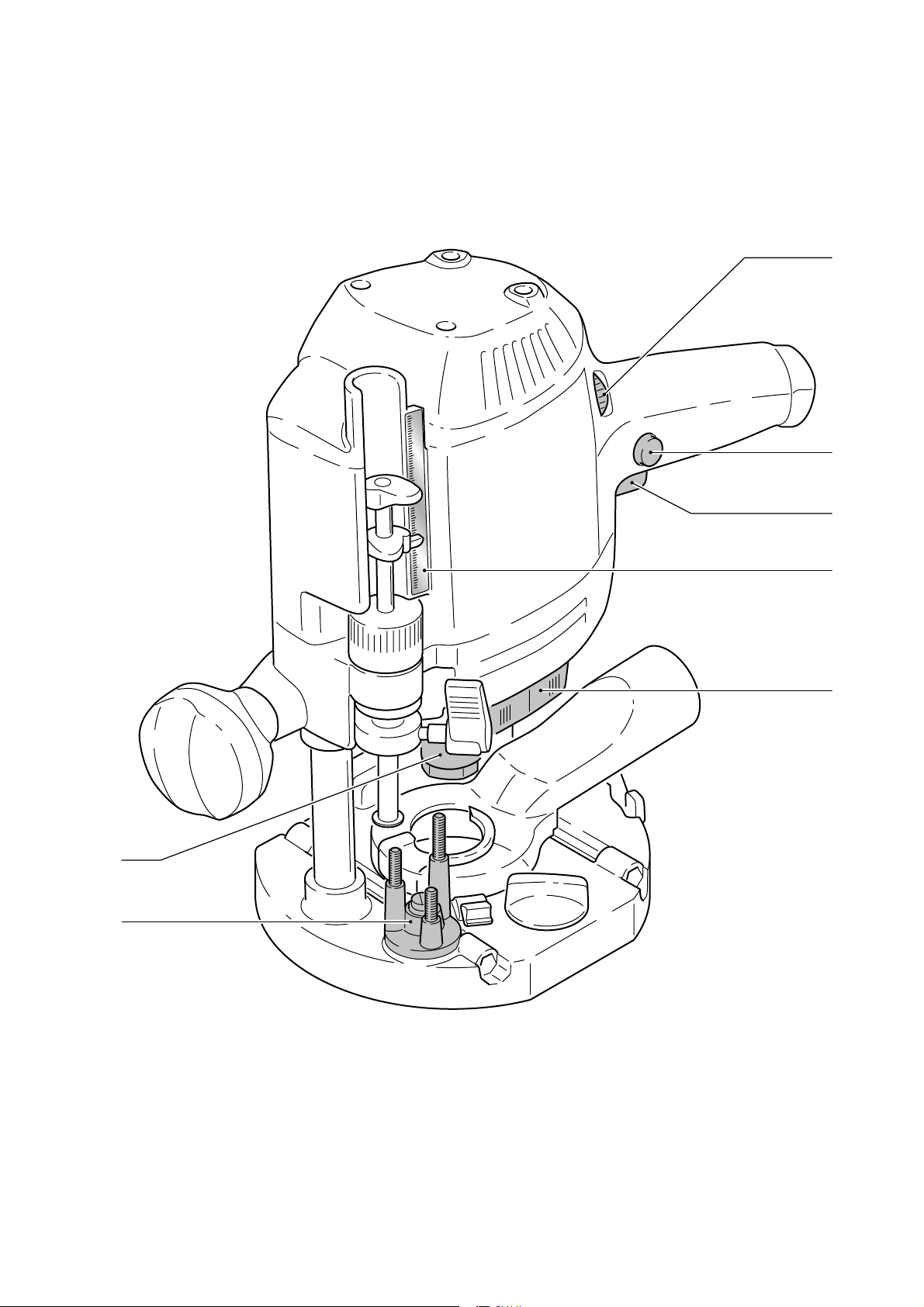
Functional description
The pictures for the functional description
are on a fold-out page at the beginning of
the instruction manual. When reading of the
manual you can fold out this page for having
always an overview of the machine.
1.1 Speed controller
1.2 Locking button
1.3 On/Off switch
1.4 Scale
1.5 Spindle stop
1.6 Pivoted turret stop
1.7 Collet nut
Electrical connection
The network voltage must conform to the
voltage indicated on the rating plate. A 16
A safety fuse (for 120 V) or a corresponding
protective circuit-breaker is required.
See the following fi gure for connection and
disconnection of the power cable.
Always switch the machine off
before connecting or disconnecting the power
cable!
2
Extension cable
If an extension cable is required, it must have
a suffi cient cross-section so as to prevent an
excessive drop in voltage or overheating. An
excessive drop in voltage reduces the output
and can lead to failure of the motor. The table
below shows you the correct cable diameter as
a function of the cable length for the router OF
1400 EQ. Use only U.L. and CSA listed extension cables. Never use two extension cables
together. Instead, use one long one.
Total Extension Cord
Lenght (feed)
Cord size (AWG) 16 14 12 10
Note: The lower the AWG number, the stronger the cable.
Switching the ma-
chine on and off
25 50 100 150
Use for intended purpose
The routers are designed for routing wood,
plastics and similar materials. Aluminium and
plasterboard can also be processed with cor-
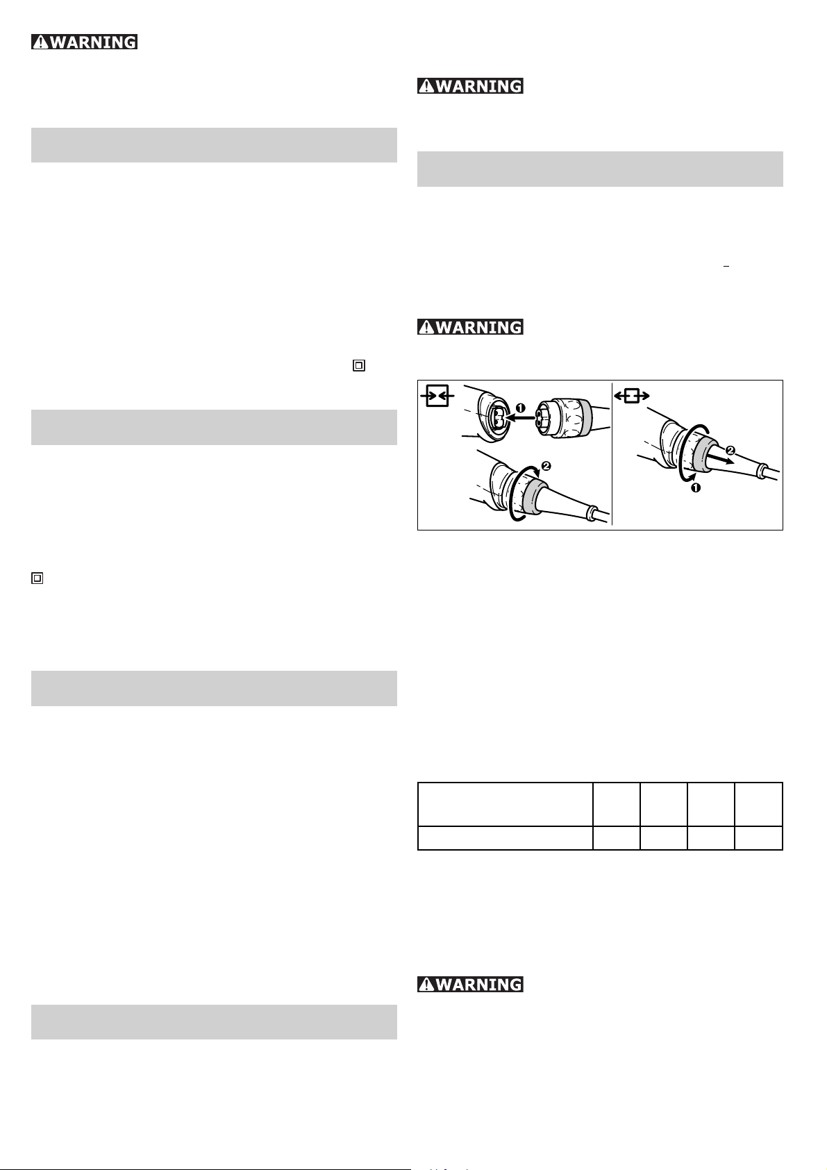
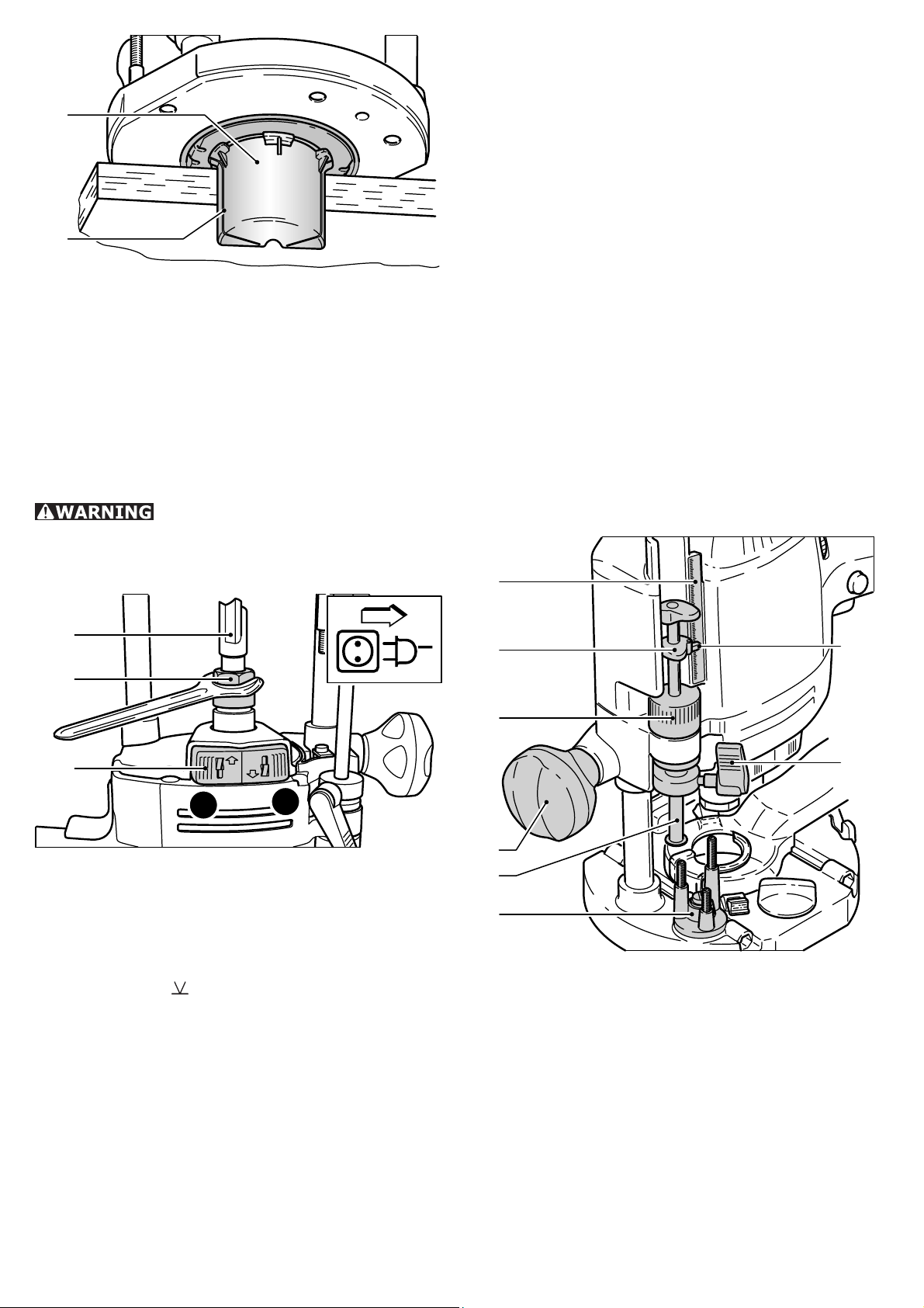
Keep the machine steady during switching and during use by holding the
handles (3.1, 3.4) with both hands.
Switch (3.3) serves as an On/Off switch. It
may be latched with the locking knob on the
side (3.2) for continuous operation. Pressing
the switch again releases the lock.
6
Page 7
3.1
3.2
3.3
3.4
After the machine has been
switched off, the milling cutter will still rotate
for a time. Take care that parts of your body
do not come into contact with the milling cutter while it is still rotating!
Constant speed:
The selected motor speed is electronically
maintained to a constant level. By this means
a uniform cutting speed is achieved.
Do not work with the OF 1400
EQ if the electronic control is defective since
this may lead to excessive speeds. A defect
in the electronic control is indicated by the
absence of a smooth run-up, a higher noise
level at idle or the fact that no speed control
is possible.
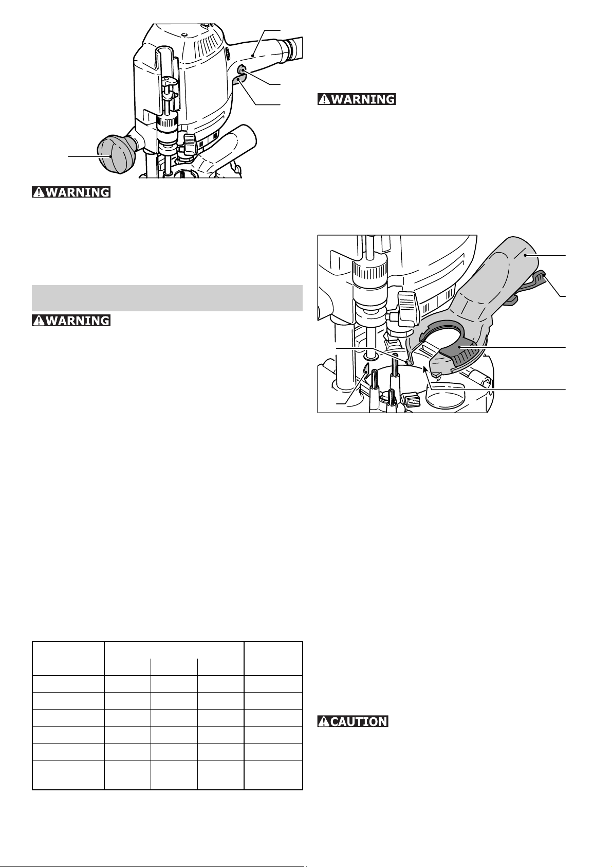
Chips extraction
4.6
Tool settings
Always disconnect the plug from
the power supply before making any adjustments to the router or installing or removing
any accessory!
Electronic control
The router OF 1400 EQ has solid shaft electronics with the following functions:
Smooth start-up:
The electronically controlled smooth startup facility enables start-up of the machine
without jerks and requires a lower start-up
current.
Speed regulation:
Using the electronic speed control (1.1) the
motor speed can be continuously adjusted
from 10000 and 22500 rpm. The table below
offers a guide to the correct electronic setting for various materials. The settings are
naturally infi nitely variable.
Material
Hard wood 6-4 5-3 3-1 HW/HSS
Soft wood 6-5 6-4 5-3 HSS/HW
Panels 6-5 6-4 4-2 HW
Plastic 6-4 6-3 3-1 HW
Aluminium 3-1 3-1 2-1 HSS/HW
Plaster-
board
Cutter diameter [mm] Cutter
10-25 25-40 40-63
2-1 1 1 HW
material
4.5
4.1
4.2
4.4
4.3
Chips and dust from routing can be removed
by means of a extractor hood. See-through
plastic material gives good view of rotating
tool. You can connect a Festool extractor
with an extractor hose diameter of 36 mm or
27 mm to the extractor connector (4.6). We
recommend a diameter of 36 mm because it
minimises the risk of blockages.
Fit the extractor hood to the router base by
–
fi rst inserting the two tenons (4.1) on the
extractor hood into the recesses (4.2) on
the router base, then place the extractor
hood on the router base and close the lever
(4.5). To enable fi tting and removing the
extractor hood with the router attached,
the recess (4.3) in the extractor hood can
be opened by turning the segment (4.4).
For optimised dust extraction, the recess
with the rotating segment must be closed
during work.
This suction hood can be used
only for cutters up to 28 mm diameter.
Chip catcher KSF-OF
Using the KSF-OF chip catcher (5.1) (sometimes included in the scope of delivery), the
effi ciency of the extraction can be increased
when routing edges.
7
Page 8
5.1
Note: the spindle lock only blocks the motor spindle in one direction of rotation at any
one time. Therefore when the nut is undone
or tightened, the wrench does not need to be
offset but can be moved back and forth like
a ratchet.
Clamping collet changing
5.2
Installation is similar to that of the copying
ring (see fi g. 12).
The hood can be cut off along the grooves
(5.2) using a hacksaw and can thus be reduced in size. The chip catcher can then be
used for interior radiuses up to a minimum
radius of 40 mm.
Milling cutters
Do not exceed the maximum
speed specifi ed on the tool and/or keep to
the speed range. Cracked or distorted cutters
must not be used.
6.3
6.2
Press the switch (6.1) for locking the spin-
–
dle on the left-hand side. Fully unscrew the
nut (6.2) and remove from spindle together
with the clamping collet.
Press the switch (6.1) for locking the spin-
–
dle on the right-hand side. Insert a new
clamping collet with nut into the spindle and
slightly tighten the nut. Do not tighten the
nut until a milling cutter has been fi tted.
Adjusting the milling depth
The milling depth is adjusted in three stages:
7.1
7.2
7.8
6.1
B
A
You can turn the machine upside down when
changing the tool.
Inserting the tool
Insert the router (6.3) into the open clamp-
–
ing collet as far as possible, but at least up
to the mark
Press the switch (6.1) for locking the spin-
–
on the router shank.
dle on the right-hand side (A).
Tighten the locking nut (6.2) with a 19 mm
–
open-end spanner.
Removing the tool
Press the switch (6.1) for locking the spin-
–
dle on the left-hand side (B).
Undo the nut (6.2) using an open-end
–
wrench (SW 19) until you are able to remove the tool.
7.3
7.4
7.5
7.6
a) Setting the zero point
Open the clamping lever (7.7) so that the
–
stop cylinder (7.5) can move freely.
Place the router with router table onto
–
a smooth surface. Open the rotary knob
(7.4) and press the machine down until
the milling cutter rests on the base. Clamp
the machine tight in this position with the
rotary knob (7.4).
Press the stop cylinder against one of the
–
three sensing stops of the pivoted turret
stop (7.6).
7.7
8
Page 9
–
The individual height of each sensing stop
can be adjusted with a screwdriver.
Sensing stop min. height max. height
A 47 mm 60 mm
A
B
C
–
Push the pointer (7.2) down so that it shows
B 53 mm 74 mm
C 60 mm 86 mm
0 mm on the scale (7.1).
If the base position is incorrect, this can be
adjusted with the screw (7.8) on the indicator.
b) Setting the milling depth
8
Support of the workpieces
Ensure that your workpieces are
securely fi xed and cannot move during rout-
ing. Otherwise, there is an increased risk of
accident. Use screw clamps or some other
suitable devices to fi x your workpiece.
The desired milling depth can be set either
with the quick depth adjustment or with the
fi ne depth adjustment.
Quick depth adjustment:
–
Pull the stop cylinder (7.5) up until the
pointer shows the desired milling depth.
Clamp the stop cylinder in this position with
the clamping lever (7.7).
Fine depth adjustment:
Clamp the stop cylinder with the clamping
–
lever (7.7). Set the desired milling depth
by turning the adjusting wheel (7.3) in.
Turn the adjusting wheel to the next mark
on the scale to adjust the milling depth by
0.1 mm. One full turn adjusts the milling
depth by 1 mm. The maximum adjustment
range with the adjusting wheel is 8 mm.
c) Increasing the milling depth
Open the rotary knob (7.4) and press the
–
tool down until the stop cylinder touches
the sensing stops.
Clamp the machine in this position by tight-
–
ening the rotary knob (7.4).
Aluminium processing
The following precautions are
to be taken when processing aluminium for
safety reasons:
Pre-connect a residual current circuit-
•
breaker.
Connect the machine to a suitable dust
•
extractor.
Clean tool regularly of dust accumulations
•
in the motor housing.
Wear protective goggles.
•
Freehand routing
Freehand routing is the method normally used
for lettering or shapes, and for routing edges
using cutters with a guide pin or ring.
Routing with the par-
allel guide
9.4
Working with the router
Always secure the workpiece
in such a manner that it cannot move while
being sawed.
The machine must always be
held with both hands by the designated
handles.
Always switch the router on fi rst
before bringing the tool into contact with the
workpiece!
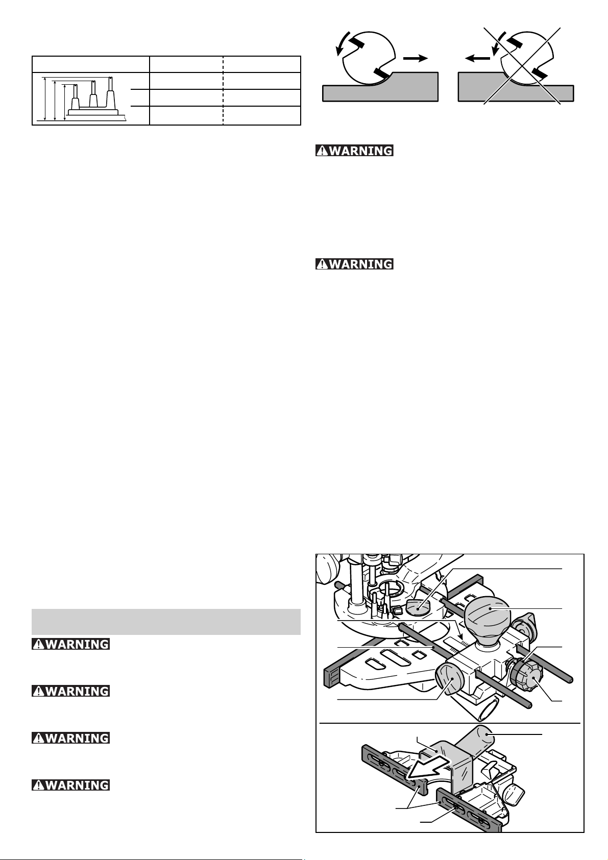
Always advance the router in
the same direction as the cutting direction of
the cutter (counter-routing)!
9.5
9.1
9.2
9.3
9.10
9.8
9.9
9
9.6
9.7
9.11
Page 10
The parallel guide (accessory) can be used
for routing parallel to the edge of the workpiece.
Secure both guide rods (9.2) with the two
–
rotary knobs (9.3) on the side stop.
Insert the guide rods into the grooves on
–
the router base to the required distance
and secure them by turning the rotary
knob (9.4).
Fine adjustment:
Unscrew the rotary knob (9.5) to make fi ne
–
adjustments with the adjusting wheel (9.7).
The scale ring (9.6) has a 0.1 mm scale
for this purpose. If the adjusting wheel is
held secure, the scale ring can be turned
separately and set to „Zero“. The millimetre scale (9.1) on the main casing is useful
when making larger adjustments. Tighten
the rotary knob (9.5) again on completion
of any fi ne adjustments.
Adjust both guidance jaws (9.8) so that
–
they are approx. 5 mm from the router. To
do this, undo screws (9.9) and tighten again
after completing the adjustments.
Slide the extractor hood (9.10) from behind
–
until it latches into place on the side stop.
You can connect an extractor hose with a
diameter of 27 mm or 36 mm to the extractor connector (9.11).
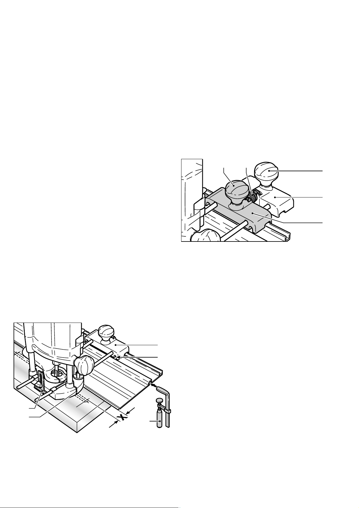
Routing with the FS
guide system
The guide system (accessory) facilitates routing straight grooves.
10.1
10.2
front edge of the guide rail and cutter or
groove is observed.
–
Place the guide stop onto the guide rail as
shown in Fig. 10. To ensure a backlashfree guidance of the router stop you can
adjust two guide cheeks with a screwdriver
through the side openings (10.2).
–
Screw the height-adjustable support (10.5)
of the router table’s threaded bore in such
a way that the underside of the router table
is parallel to the surface of the workpiece.
When working with marking-up lines, the
marks on the platen (10.4) and the scale on
the support (10.5) show the centre axis of
the cutter.
Fine adjustment
11.211.1
11.3
11.4
11.5
The distance X (fi g. 10) of the router to the
guide rail can be set fi nely using the fi ne ad-
justment (Accessories).
Fit the fi ne adjustment (11.5) between the
–
router and guide stop (11.4) on the guide
bars.
Insert the adjusting wheel (11.2) for the
–
fi ne adjustment in the recesses of the fi ne
adjustment and guide stop, and screw the
thread of the adjusting wheel approximately half way into the nut of the fi ne
adjustment.
To set, close the rotary knob (11.3) of the
–
fi ne adjustment and open the rotary knob
(11.1) of the guide stop.
After making the setting, close the rotary
–
knob (11.1) of the guide stop.
10.5
10.4
Fasten the guide stop (10.1) to the platen
–
10.3
with the guide rails of the parallel guide.
Fasten the guide rail with FSZ screw clamps
–
(10.3) to the workpiece. Make sure that
the safety distance X of 5 mm between the
Copy cutting
A copying ring or the copying device is used to
exactly reproduce existing workpieces (both
available as accessories).
10
Page 11
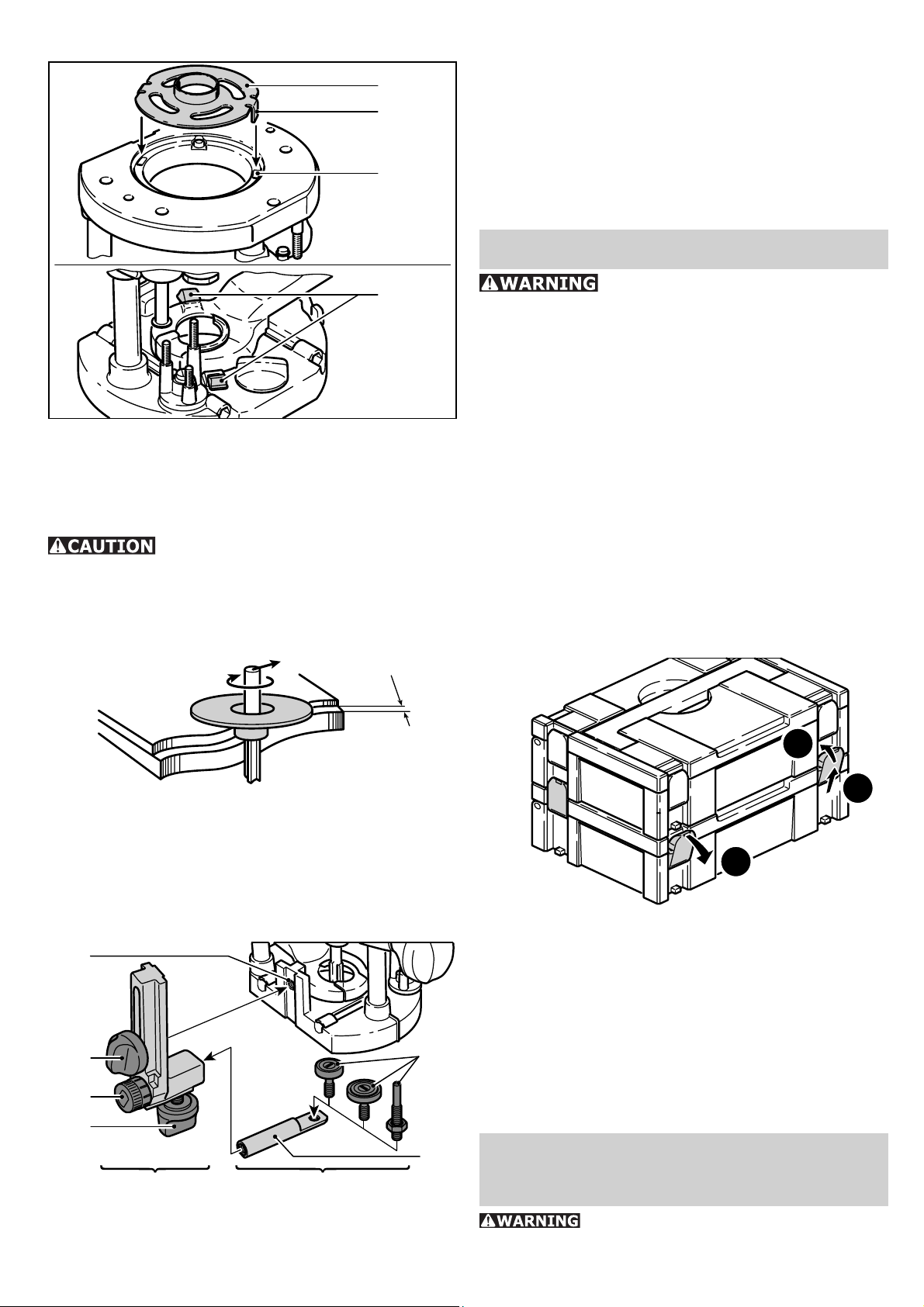
a) Copying ring
12.1
12.2
12.3
–
Fit a copying roller in the roller holder and
bolt this to the angle arm with the rotating
knob (13.4). Make sure that the copying
roller and cutter have the same diameter!
–
Turn the adjusting wheel (13.3) to adjust
the distance between the copying roller and
cutter axis.
Accessories, tools
12.4
–
Secure the copying ring (12.1) to the router
base by inserting both tenons (12.2) into
the recesses (12.3).
–
To loosen the copying ring, press both buttons (12.4) inwards simultaneously.
When choosing the size of the
copying ring make sure that the cutter used
fi ts through the ring’s opening.
The distance Y between the workpiece and
template is calculated by
Y
For safety reasons, only use
original Festool accessories and tools!
Festool offers a wide range of accessories for
the routers, e.g. to make wooden joints or
drill rows of holes.
The accessory and tool order number can be
found in the Festool catalogue or on the Internet under www.festool-usa.com.
Systainer
Many Festool products are shipped in a unique
system container, called "Systainer". This provides protection and storage for the tool and
accessories. The Systainers are stackable and
can be interlocked together. They also can be
interlocked atop Festool CT dust extractors.
Y = 1/2 (Ø copying ring - Ø cutter)
b) Copying device
The angle arm WA-OF and copier scanning set
KT-OF, consisting of roller holder (13.5) and
three copying rollers (13.6), are required for
the copying device.
13.1
13.2
13.3
13.4
WA-OF KT-OF
–
Screw the angle arm at the desired height
13.6
13.5
in the platen’s threaded bore (13.1) with
the rotating knob (13.2).
14.3
14.2
14.1
–
Place one systainer on top of the other.
–
Release all four latches on the lower systainer by pulling back at their top edges
(14.1).
–
Slide all four latches upward (14.2).
–
Snap all four latches back to their fl at po-
sition (14.3) so they engage the stacking
tabs of the upper systainer.
Servicing and
maintenance
Any maintenance or repair work
that requires opening of the motor or gear
11
Page 12

housing should only be carried out by an
authorised Customer Service Centre (name
supplied by your dealer)! Maintenance or
repair work carried out by an unauthorised
person can lead to the wrong connection of
the power leads or other components, which
in turn can lead to accidents with serious
consequences.
To prevent accidents, always remove the plug from the power supply socket
before carrying out any maintenance or repair
work on the machine! Do not use compressed
air to clean the electrical tool! Do not try to
clean parts inside the machine in this way, as
you could let foreign objects in through the
openings of the machine housing.
Certain cleaning agents and solvents are harmful to plastic parts. Some of
these are: gasoline, carbonyl chloride, cleaning solutions containing chlorine, ammonia
and household cleaners containing ammonia.
To assure the circulation of air, the cool air
vents in the motor housing must always be
kept clear and clean.
This unit is fi tted with special, automati-
cally disconnecting carbon brushes. If these
become worn, the current is automatically
switched off and the unit shuts down. In this
case, take the unit to an authorised Customer
Service Centre and have the carbon brushes
changed.
Warranty
Conditions of 1+2 Warranty
You are entitled to a free extended warranty
(1 year + 2 years = 3 years) for your Festool
power tool. Festool shall be responsible for
all shipping costs during the fi rst year of the
warranty. During the second and third year of
the warranty the customer is responsible for
shipping the tool to Festool. Festool will pay
for return shipping to the customer using UPS
Ground Service. All warranty service is valid
3 years from the date of purchase on your
receipt or invoice.
Festool Limited Warranty
This warranty is valid on the pre-condition that
the tool is used and operated in compliance
with the Festool operating instructions. Fes-
tool warrants, only to the original consumer
purchaser, that the specifi ed tool will be free
from defects in materials and workmanship
for a term of one year from the date of procurement. Festool makes no other warranty,
express or implied, for Festool portable power
tools. No agent, representative, distributor,
dealer or employee of Festool has the authority to increase or otherwise change the
obligations or limitations of this warranty. The
obligations of Festool in its sole discretion under this warranty shall be limited to the repair
or replacement of any Festool portable power
tool that is found to be defective as packaged
with the User Manual.
Excluded from coverage under this warranty
are: normal wear and tear; damages caused
by misuse, abuse or neglect; damage caused
by anything other than defects in material and
workmanship. This warranty does not apply to
accessory items such as circular saw blades,
drill bits, router bits, jigsaw blades, sanding
belts, and grinding wheels. Also excluded
are “wearing parts”, such as carbon brushes,
lamellas of air tools, rubber collars and seals,
sanding discs and pads, and batteries.
Festool portable power tools requiring replacement or repair are to be returned with the
receipt of purchase to Festool (call 800-5548741 for address details).
IN NO EVENT SHALL FESTOOL BE LIABLE
FOR ANY CONSEQUENTIAL OR INCIDENTAL DAMAGES FOR BREACH OF THIS OR
ANY OTHER WARRANTY, EXPRESSED OR
IMPLIED WHATSOEVER. ALL WARRANTIES IMPLIED BY STATE LAW, INCLUDING THE IMPLIED WARRANTIES OF
MERCHANTABILITY AND FITNESS FOR
A PARTICULAR PURPOSE, ARE HEREBY
LIMITED TO THE DURATION OF THREE
YEARS.
Some states in the U.S. and some Canadian
provinces do not allow the limitations on how
long an implied warranty lasts, so the above
limitation may not apply to you. With the exception of any warranties implied by state or
province law as hereby limited, the foregoing
express limited warranty is exclusive and in
lieu of all other warranties, guarantees, agreements and similar obligations of Festool.
This warranty gives you specifi c legal rights
and you may also have other rights which vary
from state to state in the U.S. and province
to province in Canada.
12
Page 13

Table des matières
Régles de sécurité 13
Caractéristiques techniques 15
Symbole 15
Description fonctionnelle 15
Utilisation conforme 16
Les outils électroportatifs génèrent des étincelles risquant d’enfl ammer les poussières ou
les vapeurs.
c) Tenez les enfants et autres personnes
éloignés durant l’utilisation de l’outil
électroportatif. En cas d’inattention vous
risquez de perdre le contrôle sur l’appareil.
Raccordement électrique 16
Mise en marche et arrêt de la machine 16
Réglages de l’outil 16
Electronique 16
Aspiration 17
Outils de fraisage 17
Changement de pince de serrage 18
Réglage de la profondeur de fraisage 18
Travailler avec la défonceuse 19
Appui des pièces 19
Traitement de l‘aluminium 19
Usinage à la volée 19
Fraiser avec la butée latérale 19
Fraiser avec le système de guidage FS 20
Copier un fraisage 20
Maintenance et entretien 21
Accessoires, outils 21
Garantie 22
Régles de sécurité
Assurez-vous de lire
et de bien com prendre toutes les instructions. Le non-respect, même partiel,
des instructions ci-dessous peut entraîner un
risque de choc électrique, d’incendie et/ou de
blessures graves.
CONSERVEZ CES INSTRUCTIONS
Régles de sécu-
rité générales
2) Sécurité électrique
a) La fi che de secteur de l’outil électro-
portatif doit être appropriée à la prise
de courant. Ne modifi ez en aucun cas la
fi che. N’utilisez pas de fi ches d’adapta-
teur avec des appareils avec mise à la
terre. Les fi ches non modifi ées et les prises
de courant appropriées réduisent le risque de
choc électrique.
b) Evitez le contact physique avec des
surfaces mises à la terre tels que tuyaux,
radiateurs, fours et réfrigérateurs. Il y a
un risque élevé de choc électrique au cas où
votre corps serait relié à la terre.
c) N’exposez pas l’outil électroportatif
à la pluie ou à l’humidité. La pénétration
d’eau dans un outil électroportatif augmente
le risque d’un choc électrique.
d) N’utilisez pas le câble à d’autres fi ns
que celles prévues, n’utilisez pas le câble
pour porter l’appareil ou pour l’accrocher ou encore pour le débrancher de
la prise de courant. Maintenez le câble
éloigné des sources de chaleur, des parties grasses, des bords tranchants ou des
parties de l’appareil en rotation. Un câble
endommagé ou torsadé augmente le risque
d’un choc électrique.
e) Au cas où vous utiliseriez l’outil électroportatif à l’extérieur, utilisez une
rallonge autorisée homologuée pour les
applications extérieures. L’utilisation d’une
rallonge électrique homologuée pour les applications extérieures réduit le risque d’un
choc électrique.
1) Sécurité de aire de travail
a) Maintenez l’endroit de travail propre et bien éclairé. Un lieu de travail en
désordre ou mal éclairé augmente le risque
d’accidents.
b) N’utilisez pas l’appareil dans un
environnement présentant des risques
d’explosion et où se trouvent des liquides, des gaz ou poussières infl ammables.
f) Ne tenez l‘outil qu‘à l‘aide des poignées
isolées, lorsque vous êtes susceptibles
de toucher des lignes électriques cachées ou votre propre câble électrique,
lorsque vous travaillez avec des outils de
tronçonnage. Si des outils de tronçonnage
touchent des lignes électriques, des pièces
métalliques de l‘outil peuvent être mises sous
tension et asséner une décharge électrique à
l‘utilisateur.
13
Page 14

3) Sécurité des personnes
4) Utilisation et en-
a) Restez vigilant, surveillez ce que vous
faites. Faites preuve de bon en utilisant
l’outil électroportatif. N’utilisez pas l’appareil lorsque vous êtes fatigué ou après
avoir consommé de l’alcool, des drogues ou avoir pris des médicaments. Un
moment d’inattention lors de l’utilisation de
l’appareil peut entraîner de graves blessures
sur les personnes.
b) Portez des équipements de protection.
Portez toujours des lunettes de protection. Le fait de porter des équipements de
protection personnels tels que masque antipoussières, chaussures de sécurité antidérapantes, casque de protection ou protection
acoustique suivant le travail à effectuer, réduit
le risque de blessures.
c) Evitez une mise en service par mégarde. Assurez-vous que l’interrupteur est
effectivement en position d’arrêt avant
de retirer la fi che de la prise de courant.
Le fait de porter l’appareil avec le doigt sur
l’interrupteur ou de brancher l’appareil sur la
source de courant lorsque l’interrupteur est
en position de fonctionnement, peut entraîner
des accidents.
d) Enlevez tout outil de réglage ou toute
clé avant de mettre l’appareil en fonctionnement. Une clé ou un outil se trouvant
sur une partie en rotation peut causer des
blessures.
e) Ne surestimez pas vos capacités.
Veillez à garder toujours une position
stable et équilibrée. Ceci vous permet de
mieux contrôler l’appareil dans des situations
inattendues.
f) Portez des vêtements appropriés. Ne
portez pas de vêtements amples ni de
bijoux. Maintenez cheveux, vêtements et
gants éloignés des parties de l’appareil
en rotation. Des vêtements amples, des
bijoux ou des cheveux longs peuvent être
happés par des pièces en mouvement.
g) Si des dispositifs servant à aspirer
ou à recueillir les poussières doivent
être utilisés, vérifi ez que ceux-ci soient
effectivement raccordés et qu’ils sont
correctement utilisés. L’utilisation de tels
dispositifs réduit les dangers dus aux poussières.
tretien des outils
a) Ne surchargez pas l’appareil. Utilisez
l’outil électroportatif approprié au travail à effectuer. Avec l’outil électroportatif
approprié, vous travaillerez mieux et avec
plus de sécurité à la vitesse pour laquelle il
est prévu.
b) N’utilisez pas un outil électroportatif
dont l’interrupteur est défectueux. Un
outil électroportatif qui ne peut plus être mis
en ou hors fonctionnement est dangereux et
doit être réparé.
c) Retirer la fi che de la prise de courant
avant d’effectuer des réglages sur l’appareil, de changer les accessoires, ou de
ranger l’appareil. Cette mesure de précau-
tion empêche une mise en fonctionnement
par mégarde.
d) Gardez les outils électroportatifs non
utilisés hors de portée des enfants. Ne
permettez pas l’utilisation de l’appareil
à des personnes qui ne se sont pas familiarisées avec celui-ci ou qui n’ont pas lu
ces instructions. Les outils électroportatifs
sont dangereux lorsqu’ils sont utilisés par des
personnes non initiées.
e) Prenez soin des outils électroportatifs.
Vérifi ez que les parties en mouvement
fonctionnent correctement et qu’elles ne
soient pas coincées, et contrôlez si des
parties sont cassées ou endommagées
de telle sorte que le bon fonctionnement
de l’appareil s’en trouve entravé. Faites
réparer les parties endommagées avant
d’utiliser l’appareil. De nombreux accidents
sont dus à des outils électroportatifs mal entretenus.
f) Maintenez les outils de coupe aiguisés
et propres. Des outils soigneusement entre-
tenus avec des bords tranchants bien aiguisés
se coincent moins souvent et peuvent être
guidés plus facilement.
g) Utilisez les outils électroportatifs,
les accessoires, les outils à monter etc.
conformément à ces instructions et aux
prescriptions en vigueur pour ce type
d’appareil. Tenez compte également des
conditions de travail et du travail à effectuer. L’utilisation des outils électroportatifs à
d’autres fi ns que celles prévues peut entraîner
des situations dangereuses.
14
Page 15

5) Entretien et réparation
a) Ne faites réparer votre outil électroportatif que par un personnel qualifi é et
seulement avec des pièces de rechange
d’origine. Ceci permet d’assurer la sécurité
de l’appareil.
sières spécialement conçus pour fi ltrer
les particules microscopiques.
POUR RÉDUIRE LE
RISQUE DE DOMMAGES, L'UTILISATEUR
DOIT LIRE ET COMPRENDRE LE MANUEL
D'INSTRUCTION.
Règle de sécurité parti-
culière supplémentaire
a) Tenez l’outil par ses surfaces de prise
isolées pendant toute opération où l’outil
de coupe pourrait venir en contact avec
un câblage dissimulé ou avec son propre
cordon. En cas de contact avec un conduc-
teur sous tension, les pièces métalliques à
découvert de l’outil transmettraient un choc
électrique à l’utilisateur.
b) Immobilisez l’outil sur une surface
stable au moyen de brides ou de toute
autre façon adéquate. Le fait de tenir la
pièce avec la main ou contre votre corps offre
une stabilité insuffi sante et peut amener un
dérapage de l’outil.
La poussière, un ris-
que pour la santé
Certaines poussières
créées par le ponçage mécanique, le sciage,
le meulage, le perçage et autres activités reliées à la construction contiennent des substances chimiques connues (dans l’État de la
Californie) comme pouvant causer le cancer,
des anomalies congénitales ou représenter
d’autres dangers pour la reproduction. Voici
quelques exemples de telles substances:
plomb provenant de peintures à base de
•
plomb,
silice cristallisée utilisée dans les briques,
•
le ciment et autres matériaux de maçonnerie, et
arsenic et chrome du bois d’œuvre traité
•
avec un produit chimique.
Le risque d’exposition à de tels produits varie
selon la fréquence à laquelle vous faites ce
genre de travail.
Pour réduire les risques d’exposition à
ces substances chimiques : travaillez
dans un endroit adéquatement ventilé
et utilisez un équipement de sécurité
approuvé, tel que masques antipous-
Caractéristiques
techniques
Puissance 12 A
Tension ~ 120 V, 60 Hz
Vitesse à vide 10000 - 22500 tr/min
Réglage en profondeur
rapide 70 mm (2.76“)
Réglage en profondeur fi n 8 mm (0.31“)
Filetage de broche M 22 x 1
Diamètre de fraise, maxi. 63 mm
Poids 4.5 kg (9.9 lbs)
Classe de protection
/ II
Symbole
V Volt
A Ampère
Hz Hertz
~ Tension alternative
n
Vitesse de rotation à vide
0
Classe II conception
tr/min Tours par minute
Ø Diamètre
Description fonctionnelle
Des schémas de l'outil sont disponibles sur le
volet qui se trouve au début de cette notice
d'utilisation. Vous pouvez ainsi déplier cette
page et visualiser en permanence les différentes
parties de l'outil lorsque vous lisez la notice.
1.1 Régulateur de vitesse de rotation
1.2 Bouton de blocage
1.3 Interrupteur marche/arrêt
1.4 Graduation
1.5 Dispositif d’arrêt de l’axe
1.6 Butée tournante
1.7 L’écrou de la pince de serrage
15
Page 16

Utilisation conforme
Les défonceuses sont destinées à fraiser le
bois, les matières plastiques et les matériaux
ressemblant au bois. En cas d’utilisation des
outils de fraisage prévus à cet effet dans les
documentations de vente Festool, de l’aluminium et du placoplâtre peuvent également
être traités.
Remarque: plus le numéro AWG est petit,
plus la section du câble est grande.
Mise en marche et ar-
rêt de la machine
3.1
L’utilisateur est seul
tenu responsable des dommages et des accidents qui résulteraient d’une utilisation non
conforme.
Raccordement électrique
La tension du secteur doit correspondre à
l’indication de la tension sur la plaquette signalétique. Un fusible de 16 A (à 120 V) ou
un disjoncteur de puissance approprié est
nécessaire.
Voir en fi gure suivante la connexion et la
déconnexion du câble de raccordement au
secteur.
Mettez la machine hors
marche, avant de connexion ou de déconnexion le câble de raccordement secteur.
3.2
3.3
3.4
Lors de la mise en marche
et en cours d’utilisation, tenez toujours la scie
à deux mains à les poignées (3.1, 3.4).
L’interrupteur (3.3) sert d’interrupteur marche, arrêt. L’utilisation en continue est facilitée
par le bouton de blocage (3.2) latéral. Une
nouvelle pression sur l’interrupteur libère le
blocage.
Après l’arrêt de la machine, la fraise tourne encore quelque temps.
Attention de ne pas toucher la fraise avec une
partie du corps pendant qu’elle décélère !
2
Câble de rallonge
Si une rallonge électrique est nécessaire, elle
doit présenter une section suffi sante afi n d’évi-
ter une chute de tension excessive ou une surchauffe. Une chute de tension excessive réduit
la puissance et peut entraîner la destruction
du moteur. Le tableau suivant vous présente
la section correcte du câble en fonction de sa
longueur pour la défonceuse OF 1400 EQ. Utilisez exclusivement des rallonges recommandées par U.L. et CSA. N’utilisez jamais deux
rallonges branchées l’une après l’autre, mais
remplacez-les par une rallonge plus longue.
Longueur totale
rallonge (pieds)
Section du câble
(AWG)
25 50 100 150
16 14 12 10
Réglages de l’outil
Débranchez toujours la
fi che de la source de courant avant d’entreprendre quelque réglage que ce soit sur la
scie circulaire ou avant de monter/démonter
un accessoire!
Electronique
La défonceuse OF 1400 EQ dispose d’une
électronique à ondes pleines permettant les
fonctions suivantes:
Démarrage en douceur :
Le démarrage en douceur réglé électroniquement assure un démarrage sans à-coups de
la machine et nécessite un courant de démarrage plus faible.
Réglage de la vitesse de rotation :
La vitesse de rotation peut être réglée progressivement entre 10000 et 22500 tr/min,
par l’intermédiaire d’un variateur (1.1).
16
Page 17

Le tableau suivante vous indiquera les différentes positions de l’électronique adaptées
aux matériaux fraisés. Les vitesses sont variables.
Matériau
Bois tendre 6-4 5-3 3-1 HW/HSS
Bois dur 6-5 6-4 5-3 HSS/HW
Panneaux 6-5 6-4 4-2 HW
Plastique 6-4 6-3 3-1 HW
Aluminium 3-1 3-1 2-1 HSS/HW
Placoplâtre 2-1 1 1 HW
Fraise diamètre [mm] Matériau
10-25 25-40 40-63
de l‘outil
et la dés-installation du capot d’aspiration
avec une fraise montée, le segment (4.4)
pivote, jouant ainsi sur l’ouverture (4.3)
du capot. Pour une aspiration optimale,
l’ouverture doit être fermée à l’aide du
segment pivotant (4.4) pendant le travail.
Ce capot d’aspiration peut
seulement être utilisé pour de fraises jusqu’à
un diamètre de 28 mm.
Récupérateur de copeaux KSF-OF
Vitesse constante :
La vitesse présélectionnée du moteur est
maintenue constante par un système électronique. On obtient également ainsi une vitesse
de coupe constante en cas de charge.
Cela peut entraîner une
vitesse de rotation trop élevée. Une électronique défectueuse peut être remarquée si
le démarrage progressif est inexistant, s’il
existe un bruit sourd lors de la rotation à vide
ou encore si aucun réglage de la vitesse de
rotation n’est possible.
Aspiration
4.6
4.5
5.1
5.2
Le récupérateur de copeaux KSF-OF (5.1) (en
partie dans l'équipement standard) accroît
l'effi cacité du système d'aspiration lors des
opérations d'affl eurement.
Le montage s'effectue de la même manière
que pour la bague de copiage (fi gure 12).
Le capot peut être découpé le long des gorges
(5.2) avec une scie alternative afi n de le ré-
duire. Le récupérateur de copeaux peut alors
être utilisé jusqu'à un rayon minimum de 40
mm pour les rayons intérieurs.
Outils de fraisage
4.1
4.2
4.4
4.3
Les copeaux peuvent être évacués par le
capot d’aspiration. Le plastique transparent
permet une bonne visibilité sur l’outil. Le manchon d’aspiration (4.6) permet de raccorder
un aspirateur Festool doté d’un fl exible de
36 mm ou 27 mm. Pour limiter les risques de
bourrage, nous recommandons un diamètre
de 36 mm.
Montez le capot d’aspiration sur la table de
–
fraisage en introduisant ce dernier avec les
deux tenons (4.1) dans les orifi ces (4.2) de
la table de fraisage, posez-le puis serrez le
levier (4.5). Pour permettre l’installation
La vitesse maximale indiquée sur l’outil ne doit pas être dépassée
par le haut ou resp. les limites de la vitesse
de rotation doivent être respectées. Ne pas
utiliser de fraises déformées ou usées.
Pour faciliter le changement d’outil, il est possible de retourner la machine.
6.3
6.2
6.1
B
17
A
Page 18

Insertion de l’outil
Introduire la fraise (6.3) aussi loin que
–
possible dans la pince de serrage ouverte,
au moins jusqu’au repère
de la tige de
la fraise.
Appuyer sur le bouton de blocage de broche
–
(6.1) situé sur le côté droit (A).
Serrez l’écrou (6.2) à l’aide de la clé à four-
–
che d’ouverture de 19.
7.1
7.2
7.3
7.8
Retrait de l’outil
Appuyer sur le bouton de blocage de broche
–
(6.1) situé sur le côté gauche (B).
Desserrer l’écrou (6.2) avec une clé à four-
–
che de 19 mm jusqu’à ce qu’il soit possible
de retirer l’outil.
Nota : le dispositif de blocage de broche bloque la broche motorisée dans un seul sens
de rotation. Il n’est donc pas nécessaire de
retirer la clé de serrage lors du desserrage ou
du serrage, car elle peut être déplacée comme
un cliquet.
Changement de pin-
ce de serrage
Appuyer sur le bouton de blocage de broche
–
(6.1) situé sur le côté gauche. Démontez
complètement l’écrou (6.2) et reprenez-le
de l’arbre avec la pince.
Appuyer sur le bouton de blocage de broche
–
(6.1) situé sur le côté droit. Introduisez une
nouvelle pince avec écrou dans l’arbre et
serrez l’écrou légèrement. Ne pas serrer à
fond l’écrou s’il n’y a pas de fraise!
7.7
7.4
7.5
7.6
–
Un tournevis vous permet de régler individuellement la hauteur de chacune des
butées fi xes.
Butée fi xe hauteur min. hauteur max.
A 47 mm 60 mm
A
B
C
–
Poussez l’indicateur (7.2) vers le bas, de
B 53 mm 74 mm
C 60 mm 86 mm
sorte qu’il soit dirigé sur 0 mm sur la graduation (7.1).
Si la position zéro n’est pas correcte, il est
possible de la rectifi er avec la molette (7.8)
de l’indicateur.
b) Détermination de la profondeur de
fraisage
Réglage de la profon-
deur de fraisage
Le réglage de la profondeur de fraisage s’opère
en trois étapes:
a) Réglage du zéro
Débloquez le levier de serrage de sorte
–
que la butée de profondeur (7.5) devienne
entièrement mobile.
Placez la défonceuse avec la table de fraisa-
–
ge (7.7) sur un support plan. Débloquez le
bouton rotatif (7.4) et poussez la machine
vers le bas jusqu’à ce que la défonceuse
soit en contact avec le support. Fixez la
machine au moyen du bouton rotatif (7.4)
dans cette position.
Poussez la butée de profondeur contre l’une
–
des trois butées fi xes de la butée tournante
(7.6).
La profondeur de fraisage souhaitée peut être
réglée soit par le réglage rapide en profondeur
soit par le réglage fi n en profondeur.
Réglage rapide en profondeur:
tirez la butée de profon deur (7.5) vers le
–
haut jusqu’à ce que l’indicateur indique la
pro fondeur de fraisage souhaitée. Bloquez
la butée de profon deur au moyen du levier
de serrage (7.7) dans cette position.
Réglage fi n en profondeur:
bloquez la butée de profondeur au moyen
–
du levier de serrage (7.7). Réglez la profondeur de fraisage souhaitée en tournant
le bouton moleté (7.3). En tournant le bouton d’un trait, la profondeur de fraisage se
modifi e de 0,1 mm. Un tour complet donne
lieu à une variation de 1 mm. La plage de
réglage maximale du bouton moleté est
de 8 mm.
18
Page 19

c) Réduire la profondeur de fraisage
–
Desserrez le bouton rotatif (7.4) et poussez la machine vers le bas jusqu’à ce que
la butée de profondeur soit au contact de
la butée fi xe.
–
Pour verrrouiller la position, serrer le bouton rotatif (7.4).
Travailler avec la
défonceuse
Usinage à la volée
Ce type d’usinage s’effectue essentiellement
pour les écritures et fraisage de tableaux et
pour l’usinage de chants en utilisant des fraises avec galet-butée ou avec guide-butée.
Fraiser avec la butée latérale
Pour effectuer un fraisage parallèle sur chants,
on peut utiliser la butée latérale fournie (accessoires).
Fixer la pièce à usiner
de manière à ce qu’elle ne puisse pas bouger
pendant le traitement.
Tenir la machine en toute
sécurité avec les deux mains et la dé-placer
seulement lentement vers le bas.
Avant tout contact de
l’outil avec la pièce à usiner, mettez toujours
la défonceuse en route.
Travaillez de sorte que le
sens d’avance de la défonceuse corresponde
au sens de coupe de la fraise (fraisage opposé).
8
Appui des pièces
Veillez à ce que vos pièces reposent en toute sécurité et qu’elles ne
puissent pas bouger pendant le fraisage. Vous
exposez sinon à de graves risques d’accident.
Utilisez serre-joints ou d’autres équipements
approriés pour fi xer votre pièce.
Traitement de l‘aluminium
Pour des raisons de sécurité, respecter les mesures suivantes dans
le cas du traitement de l'aluminium:
Installer un commutateur de sécurité à
•
courant de défaut (FI).
Raccorder l'outil à un aspirateur appro-
•
prié.
La machine doit régulièrement être net-
•
toyée pour éliminer les dépôts de poussières accumulées dans le corps du moteur.
Porter des lunettes de protection.
•
9.1
9.2
9.3
9.10
9.8
9.9
–
Pour serrer la butée latérale en position le
long des deux tiges de guidage (9.2), utiliser les deux molettes (9.3).
–
Introduire les tiges de guidage dans les
rainures de la table à fraiser jusqu’au point
souhaité puis les serrer avec la molette
(9.4).
Réglage fi n :
desserrer la poignée rotative (9.5) pour
–
procéder à un réglage fi n au moyen de la
molette (9.7). La bague graduée (9.6) porte
des graduations de 0,1 mm. Pour régler
la position „zéro“, maintenir la molette et
tourner la bague graduée. La graduation
en millimètres (9.1) de la partie centrale
est utile pour des réglages plus grossiers.
Une fois effectué le réglage fi n, serrer la
poignée rotative (9.5).
Régler les deux patins de guidage (9.8) de
–
manière à ce que l’écart les séparant de la
fraise soit égal à environ 5 mm. Pour cela,
desserrer les vis (9.9), puis les serrer à
nouveau une fois le réglage effectué.
9.11
9.4
9.5
9.6
9.7
19
Page 20

Monter le raccord d’aspiration (9.10) sur
–
la butée latérale par encliquetage, comme
sur l’illustration 8. Le manchon d’aspiration
(9.11) permet de raccorder un fl exible d’as-
piration de 27 mm ou 36 mm.
11.211.1
11.3
11.4
Fraiser avec le sys-
tème de guidage FS
Le système de guidage FS (accessoires) facilite le fraisage de rainures droites.
10.1
10.2
10.5
10.4
Fixez la butée de guidage (10.1) au moyen
–
des tiges de guidage de la butée latérale
sur la table de fraisage.
Fixez le rail de guidage au moyen de serre-
–
joint (10.3) sur la pièce. Veillez à ce qu’un
écart de sécurité X de 5 mm soit respecté
entre le bord avant du rail de guidage et
l’outil ou resp. la rainure.
Posez la butée de guidage sur le rail de
–
guidage comme représenté fi gure 10. Afi n
d’assurer un guidage sans jeu de la butée
de fraisage, il est possible de régler, avec
un tournevis, les deux mâchoires de guidage, au travers des deux orifi ces latéraux
(10.2).
Vissez l’appui réglable en hauteur (10.5)
–
sur le trou fi leté de la table de fraisage, de
sorte que la face inférieure de la table de
fraisage et la surface de la pièce à usiner
soient parallèles.
10.3
11.5
Installez le dispositif de réglage fi n (11.5)
–
entre la défonceuse et la butée de guidage
(11.4) sur les glissières.
Positionnez la molette (11.2) de réglage fi n
–
dans les orifi ces du dispositif de réglage fi n
ainsi que la butée de guidage, et vissez la
tige de la molette environ jusqu’à la moitié
de l’écrou du dispositif de réglage fi n.
Pour le réglage, serrez la molette (11.3) de
–
réglage fi n et desserrez la molette (11.1)
de la butée de guidage.
Une fois satisfait du réglage, serrez la mo-
–
lette (11.1) de la butée de guidage.
Copier un fraisage
Afi n de reproduire une pièce existante exac-
tement, on utilise une bague ou le système
de copiage (les deux disponibles en tant
qu’accessoire).
12.1
12.2
12.3
12.4
Afi n de pouvoir travailler suivant tracé, les
marquages sur la table de fraisage (10.4) et
la graduation sur l’appui (10.5) vous indiquent
l’axe central de la fraise.
Réglage fi n
Le dispositif de réglage fi n (accessoires) per-
met de déter miner avec précision la distance
X (fi gure 10) entre la fraise et le rail de gui-
dage.
a) Bague de copiage
Pour fi xer la bague de copiage (12.1) contre
–
la table de fraisage, insérer les deux griffes
(12.2) dans les encoches (12.3).
Pour défaire la bague de copiage, appuyez
–
simultanément vers l’intérieur sur les deux
touches (12.4).
Lors du choix de la taille
de la bague de copiage, veillez à ce que le
20
Page 21

diamètre de la fraise utilisée corresponde au
diamètre de la bague.
La saillie Y de la pièce à usiner par rapport au
gabarit se calcule comme suit :
Y
Y = 1/2 (Ø de la bague de copiage - Ø de la
fraise)
b) Système de copiage
13.1
13.2
13.3
13.6
câbles électriques ou d’autres composants,
ce qui peut provoquer des accidents avec de
graves blessures.
Afi n d’empêcher les acci-
dents, il faut toujours débrancher la fi che de
la source de courant avant toute intervention
de maintenance ou de réparation! N’utilisez
pas d’air comprimé pour nettoyer l’outil électrique ! N’essayez pas de nettoyer des pièces
à l’intérieur de la machine en introduisant des
objets par les ouvertures de l’appareil.
Certains détergents et solvants détériorent les pièces en matière plastique. Citons notamment l’essence, le chlorure
de carbonyle, les solutions de détergents
contenant du chlore, l’ammoniac et les détergents ménagers contenant de l’ammoniac. Les
ouvertures d’air de refroidissement du carter
du moteur doivent être toujours maintenues
dégagées et propres pour assurer la circulation de l’air.
13.4
13.5
WA-OF KT-OF
Le système de copiage exige le bras angulaire
WA-OF et le set de copiage KT-OF, comprenant
un support de galets (13.5) et trois galets de
copiage (13.6).
Vissez le bras angulaire, au moyen du
–
bouton rotatif (13.2), à la hauteur souhaitée sur le trou fi leté (13.1) de la table de
fraisage.
Montez un galet de copiage sur le support
–
de galets puis vissez ce dernier au moyen
du bouton rotatif (13.4) à fond sur le bras
angulaire. Veillez à ce que le rouleau de
copiage et que la fraise présentent le même
diamètre !
–
En tournant le bouton moleté (13.3), la
distance entre galet et l’axe de la fraise
peut être réglée.
La machine est équipée de charbons spéciaux
à coupure automatique. Lorsqu’ils sont usés,
le courant est auto matiquement interrompu
et la machine s’arrête. Apportez dans ce cas
votre scie dans un atelier de service aprèsvente agréé qui se chargera de remplacer les
charbons.
Accessoires, outils
Pour des raisons de sécurité,
il faut utiliser exclusivement des accessoires
et outils d’origine Festool!
Festool vous offre une large gamme d’accessoires pour les défonceuses, pour assurer
par exemple la réalisation d’assem-blages
de bois ou afi n de pouvoir percer une série
de trous.
Les références des accessoires et outils fi gu-
rent dans le catalogue Festool ou sur Internet
sous www.festool-usa.com.
Maintenance et entretien
Toutes les interventions
de maintenance et de réparation qui exigent
l’ouverture du carter du moteur ou de l’engrenage doivent uniquement être réalisées
par un atelier de service après-vente agréé
(demandez ses coordonnées à votre revendeur)! La maintenance ou la réparation de la
machine par des personnes non autorisées
peut entraîner un branchement incorrect de
Systainer
De nombreux produits Festool sont fournis
dans une caisse exclusive, appelée "Systainer". Celle-ci permet de protéger et de ranger
des outils et des appareils complémentaires.
Les Systainer sont empilables et peuvent
être solidarisés. En outre, il se fi xent sur les
aspirateurs CT Festool.
21
Page 22

14.3
14.1
Poser deux Systainer l'un sur l'autre,
–
défaire les quatre éléments de verrouillage
–
du Systainer inférieur en les tirant en arrière par leur bord supérieur (14.1).
pousser les quatre éléments de verrouillage
–
vers le haut (14.2)
manoeuvrer les quatre éléments de ver-
–
rouillage (14.3) de sorte qu'ils s'enclenchent au niveau des éléments récepteurs
du Systainer supérieur.
14.2
distributeur, vendeur ou employé de Festool
n’est autorisé à prolonger ou à modifi er les
obligations ou restrictions de la présente garantie. Les obligations de Festool sont, à son
entière discrétion, limitées à la réparation ou
à l’échange des outils portables électriques
Festool trouvés défectueux dans le présent
emballage, tels que fournis avec le présent
Guide d’utilisation.
Cette garantie exclut l’usure normale, les
dommages causés par un usage impropre,
les abus ou la négligence, ou tout dommage
autre que ceux attribuables à des défauts de
matériau et de fabrication. Cette garantie ne
s’applique pas aux accessoires tels que lames
de scie circulaire, mèches de perceuse et vilebrequin, lames de scie sauteuse, bandes abrasives et meules. Sont également exclues les
pièces d’usure, telles que balais de charbon,
lamelles pour outils à air comprimé, joints et
manchons de caoutchouc, disques et patins
ponceurs, ainsi que les piles.
Garantie
Conditions de la ga-
rantie (1+2 ans)
Vous avez droit à une prolongation de garantie
gratuite (1 an + 2 ans = 3 ans) sur votre outil
électrique Festool. Festool assumera tous les
coûts d’expédition pendant la première année
de la garantie alors que les deuxième et troisième années, les coûts devront être assumés
par le client. Festool paiera les frais de retour
de l’outil au client par service de livraison terrestre UPS. La garantie est valable pour une
période de 3 ans à compter de la date d’achat
indiquée sur votre reçu ou votre facture.
Garantie limitée de Festool
Cette garantie est valable à condition que
l’outil soit utilisé conformément aux instructions de Festool. Festool garantit, à l’acheteur
initial seulement, que l’outil indiqué sera
exempt de tout défaut de matériau et de fabrication pendant un an à compter de la date
d’achat. Festool ne donne aucune garantie
supplémentaire, implicite ou explicite, sur
les instruments portables électriques Festool. Aucun agent, représentant commercial,
Les outils électriques portables Festool à
remplacer ou à réparer doivent être retournés avec le reçu d’achat à Festool (appelez
au 800-554-8741 pour connaître l’adresse
d’expédition).
FESTOOL N’EST EN AUCUN CAS RESPONSABLE DES DOMMAGES DIRECTS
OU INDIRECTS, IMPLICITES OU EXPLICITES, DÉCOULANT DE LA RUPTURE DE
CETTE GARANTIE OU DE TOUTE AUTRE
GARANTIE. TOUTES LES GARANTIES IMPLICITES, Y COMPRIS LES GARANTIES
IMPLICITES DE QUALITÉ MARCHANDE
ET D’ADÉQUATION À UN USAGE PARTICULIER, SONT LIMITÉES À UNE PÉRIODE
DE TROIS ANS.
Certains états américains et certaines provinces canadiennes ne permettent pas la limitation des garanties implicites; il se pourrait
donc que les limites indiquées ci-dessus ne
s’appliquent pas dans votre cas. À l’exception
de certaines garanties implicites des provinces ou des états indiquées ici, la présente
garantie est exclusive et remplace toute autre
garantie, convention et obligation similaire de
Festool.
Cette garantie vous confère des droits légaux
spécifi ques, et vous pouvez aussi avoir d’autres
droits pouvant varier d’un état à l’autre, ou
d’une province à l’autre au Canada.
22
Page 23

Contenido
Normas de seguridad 23
Datos téchnicos 25
Símbolos 25
Descripción del funcionamiento 25
Use para los propósitos
intencionados 26
Conexión eléctrica 26
Conexión y desconexión de la máquina 26
Ajustes en la máquina 26
Electrónica 26
Aspiración 27
Fresas 27
Cambiar el mandril 28
Ajustar la profundidad de fresado 28
Trabajando con la fresadora 29
Apoyo de las piezas 29
Fresando metal (Aluminio) 29
Fresado a pulso 29
Fresado con tope lateral 29
Fresado con sistema de guía FS 30
Fresar copiando 30
Mantenimiento y limpieza 31
Accesorios, herramientas 32
Garantía 32
Normas de seguridad
Lea y entienda todas las
instrucciones. El incumplimiento con las
instrucciones aquí referidas puede resultar
en una descarga eléctrica, fuego y/o lesiones
personales serias.
CONSERVE ESTAS INSTRUCCIONES
líquidos, gases o material en polvo. Las
herramientas eléctricas producen chispas que
pueden llegar a infl amar los materiales en
polvo o vapores.
c) Mantenga alejados a los niños y otras
personas de su puesto de trabajo al
emplear la herramienta eléctrica. Una
distracción le puede hacer perder el control
sobre el aparato.
2) Seguridad eléctrica
a) El enchufe del aparato debe corresponder a la toma de corriente utilizada.
No es admisible modifi car el enchufe en
forma alguna. No emplear adaptadores
en aparatos dotados con una toma de
tierra. Los enchufes sin modifi car adecuados
a las respectivas tomas de corriente reducen
el riesgo de una descarga eléctrica.
b) Evite que su cuerpo toque partes conectadas a tierra como tuberías, radiadores, cocinas y refrigeradores. El riesgo
a quedar expuesto a una sacudida eléctrica
es mayor si su cuerpo tiene contacto con
tierra.
c) No exponga las herramientas eléctricas a la lluvia y evite que penetren
líquidos en su interior. Existe el peligro
de recibir una descarga eléctrica si penetran
ciertos líquidos en la herramienta eléctrica.
d) No utilice el cable de red para transportar o colgar el aparato, ni tire de él
para sacar el enchufe de la toma de corriente. Mantenga el cable de red alejado
del calor, aceite, esquinas cortantes o
piezas móviles. Los cables de red dañados
o enredados pueden provocar una descarga
eléctrica.
Normas genera-
les de seguridad
1) Seguridad del espacio de trabajo
a) Mantenga limpio y bien iluminado su
puesto de trabajo. El desorden y una ilu-
minación defi ciente en las áreas de trabajo
pueden provocar accidentes.
b) No utilice la herramienta eléctrica
en un entorno con peligro de explosión,
en el que se encuentren combustibles
e) Al trabajar con la herramienta eléctrica en la intemperie utilice solamente
cables de prolongación homologados
para su uso en exteriores. La utilización
de un cable de prolongación adecuado para
su uso en exteriores reduce el riesgo de una
descarga eléctrica.
f) Sujete la máquina únicamente por
las empuñaduras aisladas si durante los
trabajos las herramientas para separar
pueden entrar en contacto con conducciones eléctricas ocultas o incluso con
el cable de la corriente. Cuando las herra-
mientas para separar entran en contacto con
conducciones eléctricas bajo tensión, las par-
23
Page 24

tes metálicas de la máquina pueden adquirir
esta tensión y transmitir, de ese modo, una
descarga eléctrica al usuario.
3) Seguridad personal
a) Esté atento a lo que hace y emplee
la herramienta eléctrica con prudencia.
No utilice la herramienta eléctrica si
estuviese cansado, ni tampoco después
de haber consumido alcohol, drogas o
medicamentos. El no estar atento durante
el uso de una herramienta eléctrica puede
provocarle serias lesiones.
b) Utilice un equipo de protección y en
todo caso unas gafas de protección. El
riesgo a lesionarse se reduce considerablemente si, dependiendo del tipo y la aplicación de la herramienta eléctrica empleada,
se utiliza un equipo de protección adecuado
como una mascarilla antipolvo, zapatos de
seguridad con suela antideslizante, casco, o
protectores auditivos.
c) Evite una puesta en marcha fortuita
del aparato. Cerciorarse de que el aparato esté desconectado antes conectarlo a
la toma de corriente. Si transporta el apara-
to sujetándolo por el interruptor de conexión/
desconexión, o si introduce el enchufe en la
toma de corriente con el aparato conectado,
ello puede dar lugar a un accidente.
d) Retire las herramientas de ajuste o
llaves fi jas antes de conectar la herra-
mienta eléctrica. Una herramienta o llave
colocada en una pieza rotante puede producir
lesiones al ponerse a funcionar.
e) Sea precavido. Trabaje sobre una base
fi rme y mantenga el equilibrio en todo
momento. Ello le permitirá controlar mejor la
herramienta eléctrica en caso de presentarse
una situación inesperada.
f) Lleve puesta una vestimenta de trabajo
adecuada. No utilice vestimenta amplia
ni joyas. Mantenga su pelo, vestimenta
y guantes alejados de las piezas móviles. La vestimenta suelta, las joyas y el pelo
largo se pueden enganchar con las piezas en
movimiento.
g) Siempre que sea posible utilizar unos
equipos de aspiración o captación de polvo, asegúrese que éstos estén montados
y que sean utilizados correctamente. El
empleo de estos equipos reduce los riesgos
derivados del polvo.
4) Uso y cuidado de
la herramienta
a) No sobrecargue el aparato. Use la
herramienta prevista para el trabajo a
realizar. Con la herramienta adecuada po-
drá trabajar mejor y más seguro dentro del
margen de potencia indicado.
b) No utilice herramientas con un interruptor defectuoso. Las herramientas que
no se puedan conectar o desconectar son
peligrosas y deben hacerse reparar.
c) Saque el enchufe de la red antes de
realizar un ajuste en el aparato, cambiar
de accesorio o al guardar el aparato. Esta
medida preventiva reduce el riesgo a conectar
accidentalmente el aparato.
d) Guarde las herramientas fuera del
alcance de los niños y de las personas
que no estén familiarizadas con su uso.
Las herramientas utilizadas por personas
inexpertas son peligrosas.
e) Cuide sus aparatos con esmero. Controle si funcionan correctamente, sin
atascarse, las partes móviles del aparato,
y si existen partes rotas o deterioradas
que pudieran afectar al funcionamiento
de la herramienta. Si la herramienta eléctrica estuviese defectuosa haga repararla
antes de volver a utilizarla. Muchos de los
accidentes se deben a aparatos con un mantenimiento defi ciente.
f) Mantenga los útiles limpios y afi lados.
Los útiles mantenidos correctamente se dejan
guiar y controlar mejor.
g) Utilice herramientas eléctricas, accesorios, útiles, etc. de acuerdo a estas
instrucciones y en la manera indicada
específi camente para este aparato. Con-
sidere en ello las condiciones de trabajo
y la tarea a realizar. El uso de herramientas
eléctricas para trabajos diferentes de aquellos para los que han sido concebidas puede
resultar peligroso.
5) Mantenimiento
a) Únicamente haga reparar su herramienta eléctrica por un profesional,
empleando exclusivamente piezas de repuesto originales. Solamente así se mantie-
ne la seguridad de la herramienta eléctrica.
24
Page 25

Normas de seguri-
dad específi cas
a) Sujete la herramienta por la superfi -
cie de agarre aislada cuando realice una
operación donde la herramienta de corte
pueda contactar alambres ocultos o su
propio cable. El contacto con un alambre
con corriente hará traspasar la corriente a las
partes de metal de la herramienta resultando
en una descarga eléctrica al usuario.
b) Use abrazaderas u otras formas prácticas de sujetar y asegurar la pieza de
trabajo en una plataforma estable. El
sujetar la pieza de trabajo con la mano o
contra el cuerpo es inestable y puede causar
la pérdida de control.
Tensión ~ 120 V, 60 Hz
Velocidad sin carga 10000 – 22500 rpm
Ajuste rápido de
profundidad 70 mm (2.76“)
Ajuste de precisión de
profundidad 8 mm (0.31“)
Diámetro de fresa, máx. 63 mm
Alojamiento del eje de
accionamiento M 22x1
Peso 4.5 kg (9.9 lbs)
Clase de protección
/ II
Símbolos
V Voltios
A Amperios
Hz Hertzios
Riesgos para la salud pro-
ducidos por el polvo
Algunos polvos creados por
lijadoras motorizadas, aserraderos, trituradores, perforadoras y otras actividades de construcción contienen sustancias químicas que
se sabe (en el Estado de California) causan
cáncer, defectos de nacimiento u otros daños
al sistema reproductivo. Algunos ejemplos de
estas sustancias químicas son:
Plomo de las pinturas con base de plomo
•
Sílice cristalino de los ladrillos y cemento y
•
otros productos de mampostería, y
Arsénico y cromo de madera tratada con
•
sustancias químicas
El riesgo de exposición a estas sustancias
varía, dependiendo de cuantas veces se hace
este tipo de trabajo.
Para reducir el contacto con estas sus-
tancias químicas: trabaje en un área
con buena ventilación y trabaje con
equipo de seguridad aprobado, como
mascarillas para el polvo diseñadas
específi camente para fi ltrar partículas
microscópicas.
~ Rensión alterna
n
Revoluciones por minuto en vacío
0
Clase II Construcción
rpm Revoluciones por minuto
Ø Diámetro
Descripción del fun-
cionamiento
Las imágenes con la descripción de las funciones de la máquina se encuentran en una
hoja desplegable al comienzo de este manual
de instrucciones. Cuando lea este manual, le
recomendamos que despliegue esta página
para disponer fácilmente de una vista general
de la máquina.
1.1 Regulador del número de revolucio-
nes
1.2 Botón de bloqueo
1.3 Interruptor de conexión/desconexión
1.4 Escala
1.5 Dispositivo de bloqueo del husillo
1.6 Tope de revólver
1.7 Tuerca de la pinza
PARA REDUCIR EL RIES-
GO DE LESIÓN, EL USUARIO DEBE LEER
Y ENTENDER EL MANUAL DE INSTRUCCIÓN.
Datos téchnicos
Potencia 12 A
Use para los propósi-
tos intencionados
Las fresadoras son adecuadas para fresar
madera, plásticos y materiales similares a la
madera. Se pueden usar para fresar aluminio
y paneles de yeso recubiertos unilateralmente
25
Page 26

con cartón si se emplean las fresas adecuadas
según se indica en la documentación de venta
de Festool.
El usuario se responsabiliza
de los daños y accidentes debidos a un uso
inadecuado.
Conexión y desco-
nexión de la máquina
3.1
3.2
Conexión eléctrica
La tensión de la red tiene que coincidir con
lo indicado en la placa de características. Se
requiere un fusible de 16 A (con 120 V), o un
correspondiente disyuntor de protección.
Vea la fi gura siguiente para enchufar y des-
enchufar el cable de conexión.
Apague siempre la máquina
antes de conectar o sacar el cable de conexión
a la red.
2
Cable de prolongación
Cuando se necesite un cable de prolongación,
éste tiene que disponer de una sección sufi -
ciente a fi n de evitar una excesiva caída de
tensión o un sobrecalentamiento. Una excesiva caída de la tensión reduce la potencia y
puede conducir a una destrucción del motor.
En la tabla de abajo indica el diámetro de
cable correcto para la fresadora OF 1400 EQ,
a saber, en función de la longitud de cable.
Emplear únicamente los cables de prolongación listados por U.L. y CSA. No emplear
nunca dos cables de prolongación conectados
el uno con el otro. En lugar de ello, emplear
uno correspondientemente largo.
Longitud total del
cable (pies)
Diámetro de cable
(AWG)
Observación: Cuanto más bajo es el número
AWG, tanto mayor es el diámetro del cable.
25 50 100 150
16 14 12 10
3.3
3.4
La máquina tiene que ser
sujetada siempre con ambas manos por las
empuñaduras (3.1, 3.4) durante la conexión
y el uso.
El interruptor (3.3) sirve de interruptor de
conexión/desconexión. Para el servicio continuado puede engatillarse con un botón de
bloqueo lateral (3.2). Si se vuelve a pulsar el
interruptor se suelta el bloqueo.
Tras la desconexión de la
máquina, la fresa continúa girando en inercia
durante un momento. ¡Proceda con cuidado,
para evitar que la fresa entre en contacto con
al guna parte de su cuerpo mientras continúa
girando en inercia!
Ajustes en la máquina
¡Desenchufar siempre el
enchufe de la fuente de alimentación, antes
de proceder a cualquier tipo de ajustes en la
sierra circular de mano, o antes de montar o
desmontar cualquier tipo de accesorios!
Electrónica
La fresadora OF 1400 EQ dispone de un sistema electrónico de onda completa con las
siguientes funciones:
Arranque suave:
La regulación electrónica permite un arranque suave y sin sacudidas y necesita menos
corriente para el arranque.
Regulación del número de revoluciones:
La velocidad del motor se puede regular de
modo continuo entre 10000 y 22500 rpm
con el regulador de velocidad (1.1). La tabla
26
Page 27

de abajo le facilita valores aproximados para
poder trabajar con un nivel de potencia adecuado al material.
Diámetro de la fresa
Material
10-25 25-40 40-63
Madera dura 6-4 5-3 3-1 HW/HSS
Madera blan-ca6-5 6-4 5-3 HSS/HW
Tableros 6-5 6-4 4-2 HW
Plástico 6-4 6-3 3-1 HW
Aluminio 3-1 3-1 2-1 HSS/HW
Cartón de
yeso
2-1 1 1 HW
[mm]
Material
de la
fresa
Velocidad constante:
La velocidad preseleccionada para el motor
es mantenida constante electrónicamente.
De este modo se consigue una velocidad de
corte uniforme aún bajo carga.
No trabaje con la fresadora
OF 1400 EQ si el sistema electrónico no funciona correctamente, pues se podría alcanzar
una velocidad excesiva. Se reconoce que el
sistema electrónico está averiado si falta el
arranque suave, si la máquina es más ruidosa
en marcha en vacío o si no es posible regular
la velocidad.
Aspiración
–
- Monte la caperuza de aspiración en
la mesa de fresar insertando primero la
caperuza con los dos tacos (4.1) en las
entalladuras (4.2) de la mesa, luego coloque la caperuza de aspiración y mueva la
palanca (4.5). Para que sea posible montar
y desmontar la caperuza de aspiración con
la fresa montada, se puede abrir la entalladura (4.3) de la caperuza de aspiración
enroscando el segmento (4.4). Para lograr
una aspiración óptima, la entalladura debe
estar cerrada con un segmento rotatorio
durante el proceso de trabajo.
Esta caperuza de aspiración
se puede utilizar solamente para fresas hasta
el diámetro de 28 mm.
Colector de virutas KSF-OF
5.1
5.2
Mediante el colector de virutas KSF-OF (5.1)
(parcialmente en el suministro) se puede
aumentar la efectividad de la aspiración al
fresar cantos.
4.6
4.5
4.1
4.2
4.4
4.3
Las virutas producidas al fresar se pueden
aspirar mediante la caperuza de aspiración.
El plástico transparente posibilita una vista
libre a la herramienta para fresar. Se puede
conectar un aparato de aspiración Festool en
los racores de aspiración (4.6) con un diámetro de tubo de 36 mm o 27 mm. Debido
al reducido peligro de obstrucción recomendamos 36 mm.
El montaje se realiza de forma similar al anillo
copiador (fi g. 12).
La caperuza se puede recortar con una sierra
de arco a lo largo de las ranuras (5.2) reduciendo de este modo el tamaño. El colector de
virutas se puede utilizar entonces en radios
interiores hasta un mínimo de 40 mm.
Fresas
No se puede superar la velocidad máxima indicada en la herramienta,
o, lo que es lo mismo, la velocidad tiene que
mantenerse en el margen tolerado. No se
deben usar las fresas agrietadas o deformadas.
Para el cambio de herramienta puede colocar
la máquina en la cabeza.
27
Page 28

6.3
6.2
7.1
7.2
7.8
6.1
B
A
Insertar la herramienta
–
Inserte la fresa (6.3) hasta donde le sea
posible, al menos hasta la marca
en el
vástago de la fresa en la pinza abierta.
Pulse el interruptor (6.1) para el bloqueo
–
del husillo en lado derecho (A).
Apriete la tuerca (6.2) con una llave de hor-
–
quilla de ancho 19.
Retirar la herramienta
Pulse el interruptor (6.1) para el bloqueo
–
del husillo en el lado izquierdo (B).
Abra con una llave de horquilla (SW 19)
–
la tuerca (6.2) hasta que pueda extraer la
herramienta.
Nota: el bloqueo del husillo bloquea el husillo
de motor respectivo sólo en una dirección de
giro. Por este motivo, no es necesario depositar la llave de tornillos al abrir y cerrar la
tuerca, de lo contrario podría moverse de un
lado a otro como una chicharra.
Cambiar el mandril
Pulse el interruptor (6.1) para el bloqueo
–
del husillo en el lado izquierdo. Desatornille
la tuerca (6.2) completamente y sáquela,
junto con el mandril, del husillo.
Pulse el interruptor (6.1) para el bloqueo
–
del husillo en lado derecho. Ponga un nuevo
mandril con tuerca en el husillo y apriete
la tuerca ligeramente. No apriete bien la
tuerca mientras no haya metido ninguna
fresa.
7.3
7.7
7.4
7.5
7.6
a) Ponerla en cero
–
Abra la palanca de sujeción de modo que el
tope de profundidad (7.5) se pueda mover
libremente.
–
Ponga la fresadora con la base de fresado
(7.7) sobre una superfi cie plana. Abra la
ruedecilla (7.4) y empuje la máquina hacia
abajo hasta que la fresa descanse sobre
la superfi cie. Fije bien la máquina en esta
posición cerrando la ruedecilla (7.4).
–
Apriete el tope de profundidad contra uno
de los tres topes fi jos del tope de revólver
(7.6).
–
Con un destornillador puede ajustar individual-mente cada tope fi jo.
Top e fi jo altura min. altura máx.
A 47 mm 60 mm
A
B
C
Desplace el indicador (7.2) hacia abajo,
–
B 53 mm 74 mm
C 60 mm 86 mm
de modo que indique 0 mm en la escala
(7.1).
Si la posición cero no es correcta, puede corregirse con el tornillo (7.8) en el indicador.
b) Preajustar la profundidad de fresado
Ajustar la profundi-
dad de fresado
La profundidad de fresado se ajusta en tres
pasos:
Se puede preajustar la profundidad de fresado con el ajuste rápido o con el ajuste de
precisión.
Ajuste rápido de la profundidad de fresado:
Tire del tope de profundidad (7.5) hacia
–
arriba hasta que el indicador señale la
profundidad de fresado deseada. Fije el
28
Page 29

tope de profundidad en esta posición con
la palanca de sujeción (7.7).
Ajuste de precisión de la profundidad de
fresado:
Fije el tope de profundidad con la palanca
–
de sujeción (7.7). Ajuste la profundidad de
fresado deseada girando la rueda de ajuste
(7.3). Al girar la rueda una marca, la profundidad varía 0,1 mm. Un giro completo
supone 1 mm. El margen máximo de ajuste
de la rueda es 8 mm.
c) Terminar el ajuste de la profundidad
de fresado
Abra la ruedecilla (7.4) y apriete la máquina
–
hacia abajo hasta que el tope de profundidad toque al tope fi jo.
Fije la máquina en esta posición cerrando
–
el botón giratorio (7.4).
Fresando metal (Aluminio)
Al trabajar con aluminio
deberá tener presente las siguientes medidas
por motivos de seguridad:
Agregar un interruptor de corriente de de-
•
fecto (FI).
Conectar la máquina a un aparato de aspi-
•
ración apropiado.
Limpieza periódica en la máquina para
•
eliminar las aglomeraciones de polvo en el
cárter del motor.
Usar gafas de protección.
•
Fresado a pulso
Principalmente al fresar letras o fi guras o al
fresar cantos empleando fresas con anillo copiador o espiga de guía se guía la fresadora
a pulso.
Trabajando con
la fresadora
Fije la pieza de trabajo siempre de forma que no se pueda mover cuando
se trabaje con ella.
La máquina deberá sujetarse siempre con ambas manos en las empuñaduras previstas para ello.
Conecte primero la fresadora antes de tocar la pieza con la fresa.
Trabaje siempre de modo
que la dirección de avance de la fresa sea igual
a la dirección de corte de la fresa (fresado en
sentido contrario).
8
Fresado con tope lateral
Para los trabajos paralelos al canto de la pieza
se puede emplear el tope lateral (accesorio)
adjunto.
9.4
9.5
9.1
9.2
9.3
9.10
9.6
9.7
9.11
Apoyo de las piezas
Facilite en todo momento
un apoyo seguro de sus piezas, y que no se
puedan mover durante el aserrado. En caso
contrario existe un gran peligro de accidentes.
Emplee prensas de tornillo u otros dispositivos apropiados para la fi jación de su pieza.
9.8
9.9
Fije las dos barras guía (9.2) con los dos
–
botones giratorios (9.3) en el tope lateral.
Introduzca las barras guía hasta la medida
–
deseada en las ranuras de la mesa de fresar
y fíjelas con el botón giratorio (9.4).
Ajuste fi no:
Abra el botón giratorio (9.5) para efectuar
–
un ajuste fi no con la rueda de ajuste (9.7).
El anillo graduado (9.6) tiene una escala de
29
Page 30

0,1 mm. Si se sujeta la rueda de ajuste, el
anillo graduado puede girarse para situarlo en la posición „Cero“. En caso de unos
ajustes mayores, la escala milimétrica (9.1)
junto al cuerpo base puede ser de ayuda.
Cierre nuevamente el botón giratorio (9.5)
una vez efectuado satisfactoriamente el
ajuste fi no.
Ajuste las dos mordazas de guía (9.8) de
–
tal modo que su distancia respecto a la
fresa sea de aprox. 5 mm. Para ello, deberán abrirse los tornillos (9.9) y volverse a
apretar tras efectuar con éxito el ajuste.
Desplace la caperuza de aspiración (9.10)
–
desde atrás hasta enclavarla en el tope
lateral. En los racores de aspiración (9.11)
puede conectarse un tubo fl exible de as-
piración con un diámetro de 27 mm o 36
mm.
Fresado con siste-
ma de guía FS
Este sistema de guía suministrable (accesorio)
especial facilita el fresado de ranuras rectas.
10.1
10.2
Para poder trabajar con un patrón, la marca
en la base de la fresadora (10.4) y la escala
del apoyo (10.5) le indican el eje medio de
la fresa.
Ajuste fi no
Con el ajuste fi no (accesorios) la distancia X
(fi g. 12) de la fresa respecto al riel de la guía
se puede ajustar suavemente.
11.211.1
11.3
11.4
11.5
–
Coloque el ajuste fi no (11.5) entre la fresa-
dora y el tope de guía (11.4) en las barras
de guía.
–
Coloque la rueda de ajuste (11.2) para el
ajuste fi no en las entalladuras del ajuste
fi no y del tope de guía y apriete la rosca de
la rueda de ajuste aproximada-mente hasta
la mitad de la tuerca del ajuste fi no.
–
Para hacer el ajuste, cierre el botón giratorio (11.3) del ajuste fi no y abra el botón
giratorio (11.1) del tope de guía.
–
Tras haber efectuado satisfactoriamente el
ajuste, cierre el botón giratorio (11.1) del
tope de guía.
10.5
10.4
Fije el tope de guía (10.1) con garras me-
–
10.3
tálicas en la base de fresado.
Fije la guía con sargentos (10.3) en la pieza
–
de trabajo. Asegúrese de que hay una distancia de seguridad X de 5 mm entre el lado
delantero de la guía y la fresa o ranura.
Ponga el tope de guía, así como se muestra
–
en la fi gura 10, en la guía. Para garantizar
una guía sin holgura del tope de fresado,
empleando un destornillador puede ajustar
dos zapatas de guía a través de los dos
orifi cios (10.2).
Meta el apoyo (10.5) regulable en altura
–
en el agujero roscado (de la base de la
fresadora, de modo que la parte inferior
de la base sea paralela a la superfi cie de
la pieza.
Fresar copiando
12.1
12.2
12.3
12.4
Para reproducir con exactitud las piezas
existentes se emplea un anillo copiador o un
30
Page 31

sistema copiador (como accesorios especiales
en ambos casos).
a) Anillo copiador
Sujete el anillo copiador (12.1) en la mesa
–
de fresar insertando ambos tacos (12.2) en
las entalladuras (12.3).
Para afl ojar el anillo copiador, mantener
–
pulsadas ambas teclas (12.4) simultáneamente.
A la hora de elegir el tamaño
del anillo copiador asegúrese de que la fresa
puesta pasa por su abertura.
El sobrante Y de la pieza respecto al patrón
se calcula del siguiente modo:
Y
Y = 1/2 (Ø de anillo copiador - Ø de fresa)
b) Sistema copiador
Para el sistema copiador se precisa el brazo
angular WA-OF y el set de copiar KT-OF, consistente en una sujeción de rodillo (13.5) y
tres rodillos copiadores (13.6).
13.1
13.2
13.3
13.4
WA-OF KT-OF
Atornille bien el brazo angular con la ruede-
–
cilla (13.2) a la altura deseada en el agujero
roscado (13.1) de la base de la fresadora.
Monte un rodillo copiador en la sujeción
–
de rodillo y sujételo bien al brazo angular
girando la ruedecilla (13.4). Asegúrese de
que el rodillo copiador y la fresa tienen el
mismo diámetro.
Girando la rueda de ajuste (13.3) se puede
–
regular la distancia del rodillo copiador al
eje de la fresa.
13.6
13.5
Mantenimien-
to y limpieza
Todos los trabajos de mantenimiento y de repara ción que requieran una
abertura de la carcasa del motor o del mecanismo de transmisión, solamente deben ser
llevados a cabo por un taller de servicio de
asistencia técnica autorizado (su concesionario le facilitará la información adecuada)! Un
man-tenimiento o reparación de la máquina
por personas no autori-zadas puede ser la
causa de una conexión errónea de los cables
conductores de corriente eléctrica o de otros
componentes, lo cual puede ser la causa de
accidentes con lesiones graves.
¡A fi n de evitar accidentes,
antes de proceder a todo tipo de trabajos de
mantenimiento o de reparación en la máquina se tiene que desenchufar el enchufe de
la fuente de alimentación de corriente! ¡No
emplear aire comprimido para limpiar la herramienta eléctrica! No intente nunca limpiar
piezas en el interior de la máquina introduciendo algún objeto a través de las aberturas
de la carcasa de la máquina.
Algunos detergentes y disolventes pueden dañar los componentes de
material sintético. Entre éstos se encuentran:
Bencina, carbonilcloruro, soluciones detergentes de contenido de cloro, amoniaco, así como
detergentes de uso doméstico amónicos. A
fi n de garantizar la circulación del aire, las
aberturas para el aire de refrigeración en la
carcasa del motor tienen que ser mantenidas
continuamente libres y limpias.
El aparato está equipado con escobillas especiales de autodesconexión. Al desgastarse,
se efectúa una interrupción automática de la
corriente y la máquina se para. En este caso,
el aparato deberá ser llevado a un taller de
servicio de asistencia técnica autorizado, donde se cambiaran las escobillas.
Accesorios, herramientas
¡Por razones de seguridad,
solamente deben emplearse accesorios y herramientas originales de Festool!
Festool ofrece gran número de accesorios
para sus fresadoras, por ej. para fresar conglomerado de madera, para perforar orifi cios
31
Page 32

en línea o para un uso estacionario de la fresadora.
Los números de pedido para los respectivos
accesorios y herramientas se encuentran en
su catálogo Festool o en la dirección de Internet www.festool-usa.com.
Systainer
Muchos de los productos Festool se entregan
en un embalaje exclusivo denominado "Systainer" que sirve de protección a la herramienta y sus complementos, además de facilitar
su almacenamiento. Los Systainer pueden
apilarse y encajan unos con otros. Además
se adaptan sin problema a cualquier aparato
de aspiración CT de Festool.
14.3
14.2
14.1
Todo el servicio de garantía es válido por 3
años desde la fecha de la compra de acuerdo
a la fecha de su recibo o factura de compra.
Garantía limitada de Festool
Esta garantía es válida con la condición previa de que la herra mienta se usa y opera
de conformidad con las instrucciones de
operación de Festool. Festool garantiza, sólo
al comprador original, que la herramienta
especifi cada estará libre de defectos de fa-
bricación y materiales durante un periodo de
un año a partir de la fecha de compra. Festool no otorga otras garantías, ni explícitas ni
implícitas para ninguna de las herramientas
mecánicas portátiles Festool. Ningún agente, representante, distribuidor, comerciante
o empleado de Festool está autorizado para
extender o modifi car de cualquier manera las
obligaciones o limitaciones de esta garantía.
Las obligaciones de Festool, a su propia entera
discreción, están limitadas a la reparación o
sustitución de cualquier herramienta portátil
Festool que se encuentre estar defectuosa
en el momento de ser embalada junto con el
manual de usuario.
Coloque un Systainer sobre otro.
–
Abra los cuatro enganches del Systainers de
–
abajo tirando de sus extremos superiores
(14.1).
Deslice los cuatro enganches hacia arriba
–
(14.2).
Presione los cuatro enganches hasta que
–
queden planos (14.3) y puedan así acoplarse en los soportes del Systainer colocado
encima.
Garantía
Condiciones de la Ga-
rantía 1 + 2
Usted tiene derecho a una garantía extendida
gratuita (1 año + 2 años = 3 años) para su
herramienta mecánica Festool. Festool se hará
responsable por los gastos de envío durante
el primer año de garantía. Durante el segundo
y tercer año de garantía el cliente es responsable por el costo del envío de la herramienta
a Festool. Festool pagará el embarque de regreso al cliente usando UPS Ground Service.
Quedan excluidos de la cobertura en esta garantía: el desgaste normal; los daños causados por uso indebido, el abuso o negligencia;
los daños causados por cualquier otra causa
que no sean defectos del material o de la fabricación. Esta garantía no aplica a accesorios
como cuchillas de sierras circulares, brocas de
taladro, barrenas de buriladora, cuchillas de
sierra, cuchillas para sierras de calado, correas
de lijadoras y ruedas de esmeril. También se
excluyen las “partes que se desgastan” como
cepillos de carbón, laminillas de herramientas
de aire, collarines de hule y sellos, discos y
cojines de lijado, y baterías.
Las herramientas mecánicas portátiles Festool que requieran de reemplazo o reparación
deben devolverse con el recibo de compra a
Festool (llame al 800-554-8741 para los detalles de la dirección).
EN NINGÚN CASO FESTOOL SE HARÁ
RESPONSABLE POR LOS DAÑOS SECUNDARIOS O CONSECUENTES OCASIONADOS POR LA VIOLACIÓN DE ESTA
O CUALUQUIER OTRA GARANTÍA, SEA
EXPLÍCITA O IMPLÍCITA. TODAS LAS
GARANTÍAS IMPLICADAS POR LEYES
ESTATALES, INCLUYENDO LAS GARAN-
32
Page 33

TÍAS IMPLICADAS DE COMERCIALIZACIÓN Y ADECUACIÓN A UN PROPÓSITO
PARTICULAR, QUEDAN LIMITADAS A
TRES AÑOS DE DURACIÓN.
Algunos estados de EE.UU. y algunas provincias de Canadá no permiten las limitaciones en
cuanto a la duración de las garantías implícitas, de modo que la limitación arriba indicada
puede que no le afecte. A excepción de algunas garantías implicadas por leyes estatales
o provinciales, limitadas por la presente, la
anteriormente citada garantía, expresamente
limitada, es exclusiva y sustituye a cualquier
otra garantía, acuerdo u obligación similar de
Festool.
Esta garantía le concede derechos legales
específi cos y usted podría tener otros dere-
chos legales que varían de estado a estado
en EE.UU. y de provincia a provincia en Canadá.
33
Page 34

34
 Loading...