

Festool UG-KAPEX KS120, KA-UG-KS120-L, KA-UG-KS120-R, KA-KS120 Assembly Instructions Manual
Page 1
Festool GmbH
Wertstraße 20
D-73240 Wendlingen
Tel.: +49 (0)7024/804-0
Telefax: +49 (0)7024/804-20608
www.festool.com
Montageanleitung - Untergestell 6
Assembly instructions - Base frame 9
Notice d’emploi - Châssis 11
Instrucciones de montaje - Bastidor inferior 14
Istruzioni di montaggio - Sottotelaio 17
Montagevoorschrift - Onderstel 19
Monteringsanvisning - Stativ 22
Asennusohje - Konealusta 24
Montagevejledning - Understel 26
Monteringsveiledning - Stativ 28
Instruções de montagem - Leito 30
Руководство по эксплуатации - Подставка 33
Návod k montáži - Podstavec 36
Instrukcja montażu - Podstawa 38
UG-KAPEX KS120
KA-KS120
709631_002
Page 2
1-2
1-1
1-1
1-3
4x
4x
1x
1x
1-4
1-5
UG-KAPEX-KS120
KA-UG-KS120-L
KA-UG-KS120-R
4x
1A
1
2
2
1
4x
Page 3
60°
KS 120 EB
KS 88 E
2
3
4
5
x
x
x
x
x
x
Page 4
1
2
6
7
8
910
Page 5
+
-
+
12
11
13
Page 6
UG-KAPEX KS 120
D
1Symbole
Symbol Bedeutung
Warnung vor allgemeiner Gefahr
Betriebsanleitung, Sicherheitshinweise
lesen!
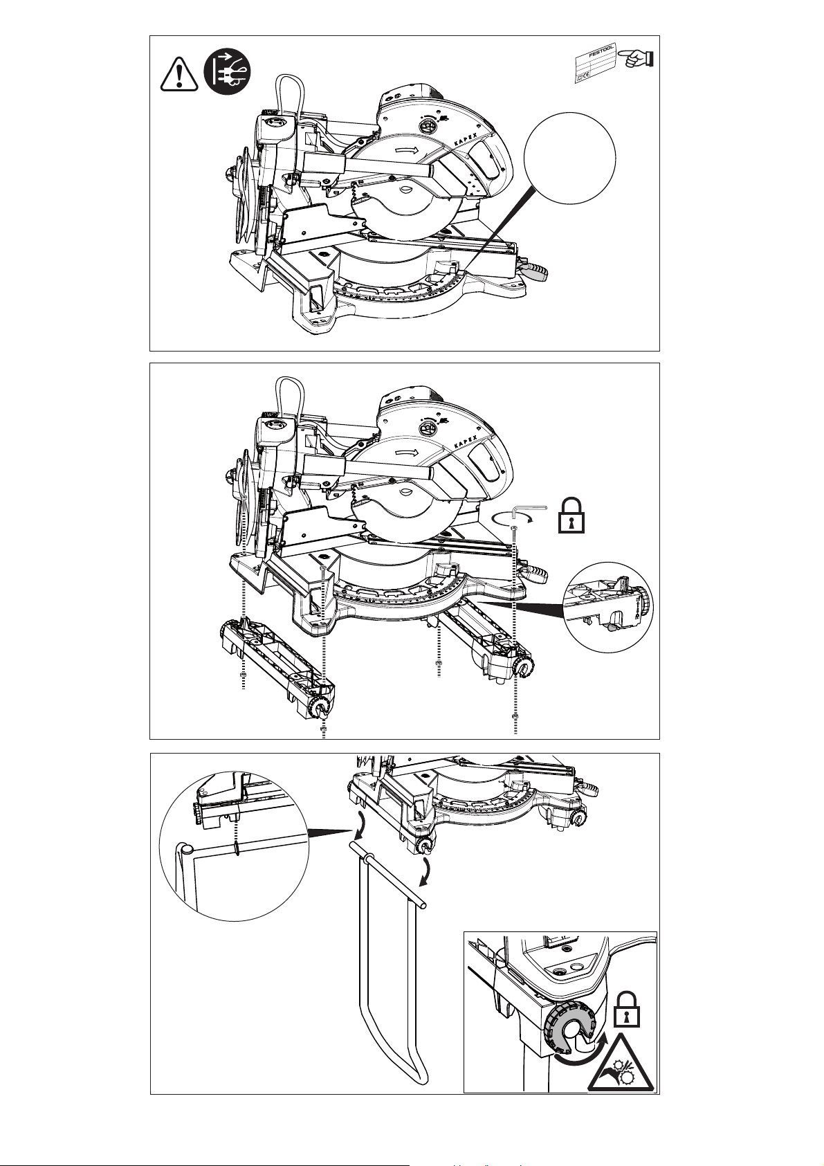
Netzstecker ziehen!
VORSICHT! Quetschen der Finger!
Die angegebenen Abbildungen befinden sich am
Anfang und am Ende der Betriebsanleitung.
3 Technische Daten
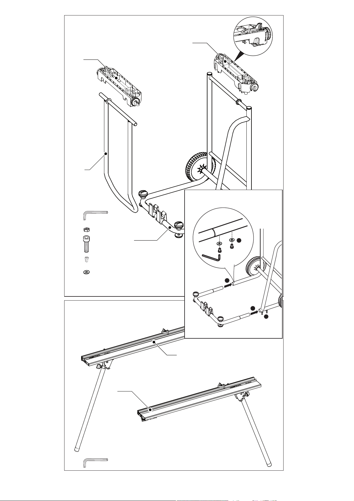
2Lieferumfang
Untergestell UG-KAPEX KS 120
[1-1]
[1-2]
[1-3]
Kappanschlag KA-UG-KS120
[1-4]
[1-5]
2 x Aufnahmeschienen
1 x Untergestell mit Rollen (zweigeteilt)
1 x Klapp-/Standbügel, Schubbügel
4 x Schrauben M6x60
4 x Muttern M6
4 x Schrauben M6x16
4 x Unterlegscheiben D6,4
1 x Sechskantschlüssel
linker Kappanschlag KA-UG-KS120-L
rechter Kappanschlag KA-UG-KS120-R
1 x Sechskantschlüssel
Untergestell UG-KAPEX KS 120
Länge Untergestell ohne Kappanschlag 560 mm
Länge Untergestell mit einseitigem Kappanschlag 1760 - 2680 mm
Länge Untergestell mit beidseitigem Kappanschlag 2960 - 4810 mm
Arbeitshöhe 900 mm
max. Traglast UG-KAPEX KS 120 / KA-UG-KS120 100/20 kg
Gewicht UG-KAPEX KS 120 ohne Kappsäge 10,1 kg
Gewicht KA-UG-KS120 4,6 kg
4 Bestimmungsgemäße Verwen-
dung
Das Untergestell UG-KAPEX KS 120 ist bestimmungsgemäß für den Gebrauch mit Festool Kappsägen - KS 120 EB und KS 88 E - vorgesehen.
Der Kappanschlag KA-UG-KS120 ist bestimmungsgemäß vorgesehen zur Montage am Untergestell UG-KAPEX KS 120.
Zusammen mit dem Elektrowerkzeug ist das Untergestell bestimmt zum Sägen von Brettern und
Profilen.
WARNUNG
Für Schäden und Unfälle bei nicht bestimmungsgemäßem Gebrauch haftet der Benutzer.
5 Sicherheitshinweise
WARNUNG!
hinweise und Anweisungen.
Einhaltung der Sicherheitshinweise und Anweisungen können elektrischen Schlag, Brand und/oder
schwere Verletzungen verursachen.
Bewahren Sie alle Sicherheitshinweise und Anweisungen für die Zukunft auf.
–
Ziehen Sie den Stecker aus der Steckdose bevor
Sie Geräteeinstellungen vornehmen oder Zubehörteile wechseln.
Elektrowerkzeugen ist die Ursache einiger Unfälle.
–
Bauen Sie das Untergestell korrekt auf, bevor
Sie das Elektrowerkzeug montieren.
freier Aufbau ist wichtig, um das Risiko eines Zusammenbrechens zu verhindern.
Befestigen Sie das Elektrowerkzeug sicher am
–
Untergestell, bevor Sie es benutzen.
Lesen Sie alle Sicherheits-
Versäumnisse bei der
Unbeabsichtigter Start von
Einwand-
Ein Verrut-
6
Page 7

schen des Elektrowerkzeugs auf dem Untergestell kann zum Verlust der Kontrolle führen.
–
Stellen Sie das Untergestell auf eine feste, ebene und waagerechte Fläche.
Wenn das Untergestell verrutschen oder wackeln kann, können das
Elektrowerkzeug oder das Werkstück nicht
gleichmäßig und sicher geführt werden.
Überlasten Sie das Untergestell nicht und ver-
–
wenden Sie dieses nicht als Leiter oder Gerüst.
Überlastung oder Stehen auf dem Untergestell
kann dazu führen, dass sich der Schwerpunkt
des Untergestells nach oben verlagert und dieser umkippt.
Achten Sie darauf, dass beim Transport und
–
beim Arbeiten sämtliche Schrauben und Verbindungselemente fest angezogen sind.
Die
Aufnahmeschienen für das Elektrowerkzeug
müssen immer fest arretiert sein. Lockere Verbindungen können zu Instabilitäten und ungenauen Sägevorgängen führen.
–
Montieren und demontieren Sie das Elektrowerkzeug nur, wenn es in Transportstellung ist
(Beschreibung siehe Betriebsanleitung Ihrer
Kappsäge).
Das Elektrowerkzeug kann sonst einen so ungünstigen Schwerpunkt haben, dass
Sie es nicht sicher halten können.
Stellen Sie sicher, dass lange und schwere
–
Werkstücke das Untergestell nicht aus dem
Gleichgewicht bringen.
Lange und schwere
Werkstücke müssen am freien Ende unterlegt
oder abgestützt werden.
– Nicht mittels Kranhaken oder Hebezeug hochhe-
ben und transportieren!
6Montage
6.1 Untergestell UG-KAPEX KS 120
Zweigeteiltes Untergestell zusammenbauen
[1A]
.
Kappsäge in Transportstellung bringen
schreibung siehe Bedienungsanleitung Ihrer
Kappsäge).
Aufnahmeschienen montieren
Klapp-/Standbügel an Kappsäge mit Aufnah-
[3]
meschienen einsetzen und verriegeln
Kappsäge mit Aufnahmeschienen auf Untergestell setzen und verriegeln
Klapp-/Standbügel am Untergestell einrasten
[8]
.
[6 + 7]
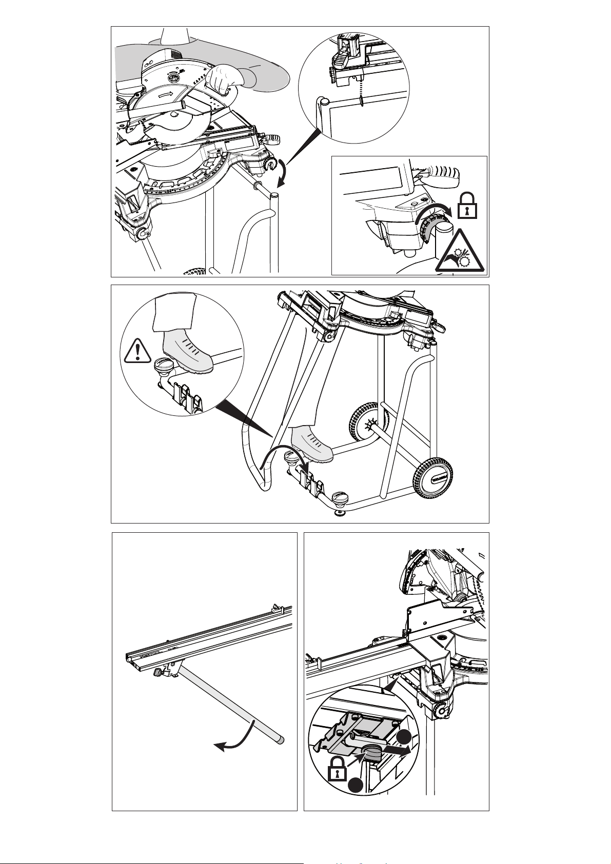
6.2 Kappanschlag KA-UG-KS120
Abbildungen für linken Kappanschlag - Die
Montage des rechten Kappanschlags erfolgt
analog.
.
.
[2]
(Be-
[4 + 5]
.
UG-KAPEX KS 120
Stützfuß ausklappen
Kappanschlag auf Nut aufsetzen, Pratze klem-
[10]
men
.
[9]
.
D
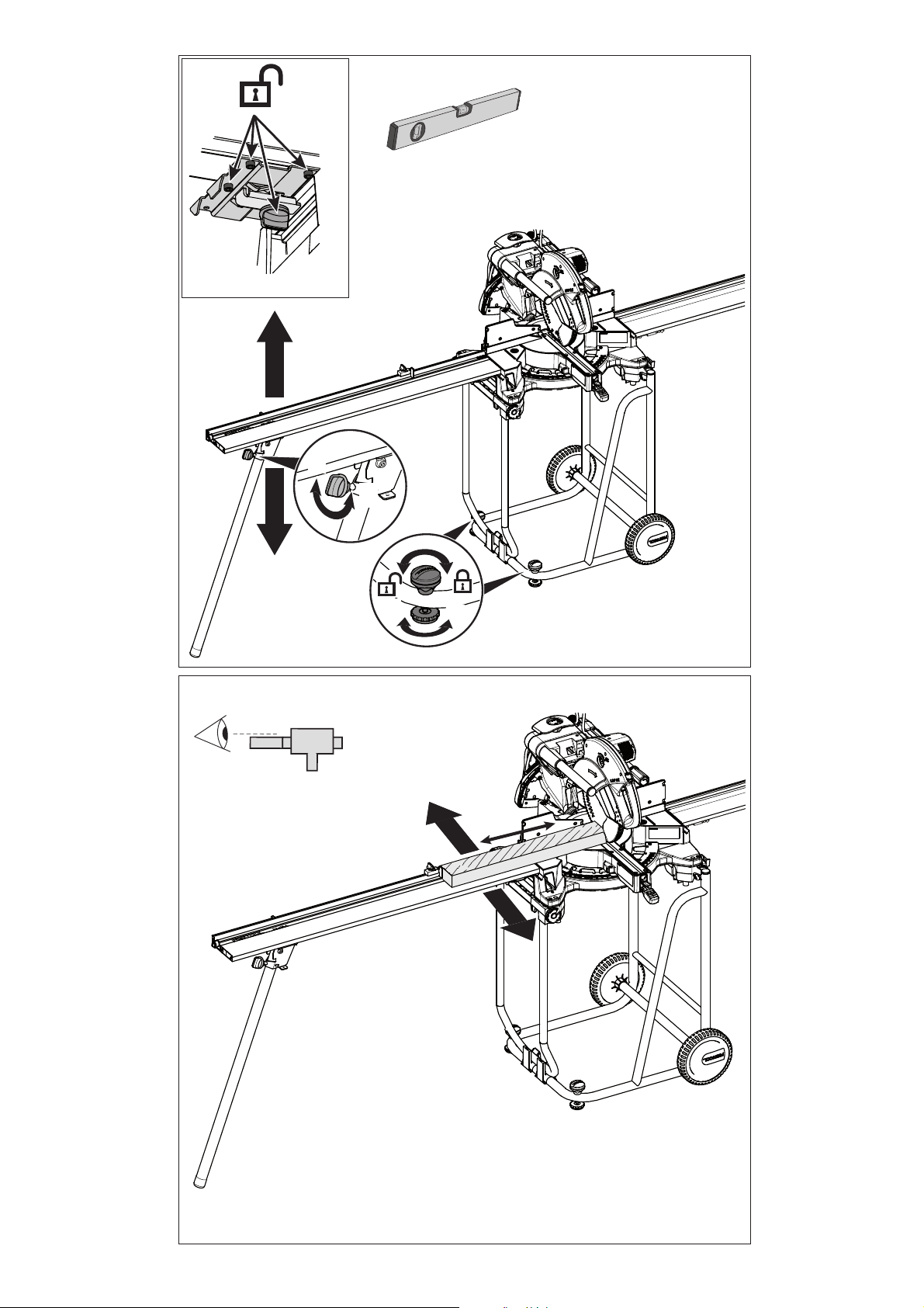
7 Einstellungen
Nehmen Sie vor der ersten Verwendung folgende
Einstellungen vor:
Pratze und Sechskant-Schrauben am Kappan-
[11]
schlag öffnen
Waagrechte einstellen
Flucht einstellen
Skala einstellen
Pratze und Sechskant-Schrauben klemmen
[15]
.
.
[13]
[14]
.
[12]
.
.
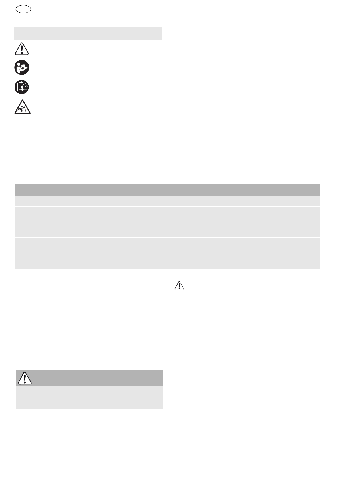
8 Arbeiten mit der Maschine
Folgende Hinweise beachten:
– Überlasten Sie das Untergestell nicht. Beachten
Sie die maximale Traglast.
– Stellen Sie sicher, dass beim Arbeiten immer alle
Drehverschlüsse geschlossen sind.
– Klemmen Sie das Werkstück immer fest, beson-
ders den längeren, schweren Abschnitt. Nach
dem Durchtrennen des Werkstücks kann sich
der Schwerpunkt ungünstig verlagern und das
Untergestell kippen.
Teleskopauszug betätigen
Bei Lagerung über einen längeren Zeitraum:
UG-KAPEX KS 120 mit KS 120 wie in Bild
[16]
.
[21]
dargestellt abstellen.
9Transport
Kappsäge in Transportstellung bringen
[2]
(Beschreibung siehe Bedienungsanleitung Ihrer
Kappsäge).
Klapp-/Standbügel lösen und Säge einklappen
[17]
.
Position verriegeln
Wenn sie beide Kappanschläge im Set gekauft
[18]
.
haben, können Sie diese mit den Transport-
[19]
Kappen mit Gurt
xieren
Das Untergestell kann stehend
gend
[20]
.
[21]
transportiert werden.
auf dem Untergestell fi-
[20]
oder lie-
10 Umwelt
Werfen Sie das Gerät nicht in den Hausmüll!
ren Sie die Geräte, Zubehör und Verpackungen einer umweltgerechten Wiederverwertung zu. Beachten Sie die geltenden nationalen Vorschriften.
Informationen zur REACh:
www.festool.com/reach
Füh-
7
Page 8
UG-KAPEX KS 120
EKAT
1
2
3
5
4
D
Kundendienst und Reparatur
nur
durch Hersteller oder durch Servicewerkstätten: Nächstgelegene Adresse
unter: www.festool.com/service
Nur original Festool Ersatzteile verwenden! Bestell-Nr. unter:
www.festool.com/service
Die Bestellnummern für Zubehör und
Werkzeuge finden Sie in Ihrem Festool
Katalog oder im Internet unter „www.festool.com“.
8
Page 9
UG-KAPEX KS 120
GB
1Symbols
Symbol Significance
Warning of general danger
Read operating instructions and safety
notices!
Disconnect from the power supply!
CAUTION! Risk of injury to fingers.
The illustrations specified are located at the beginning and end of the operating manual.
2Scope of delivery
Base frameUG-KAPEX KS 120
[1-1]
[1-2]
[1-3]
Trimming attachment KA-UG-KS120
[1-4]
[1-5]
2 x retaining rails
1 x base frame with rollers (two-part)
1 x folding/fixed stirrup, handle
4 x M6x60 screws
4 x M6 nuts
4 x screws M6x16
4 x D6.4 plain washers
1 x Allen key
Left trimming attachment KA-UG-KS120L
Right trimming attachment KA-UGKS120-R
1 x Allen key
3Technical data
Base frame UG-KAPEX KS 120
Length of base frame without trimming attachment 560 mm (15-3/4")
Length of base frame with trimming attachment on one side 1760 - 2680 mm (5’ 25/32" - 8’ 51/64")
Length of base frame with trimming attachment on both sides 2960 - 4810 mm (9’ 23/32" - 15’ 25/32")
Working height 900 mm (35-7/16")
Max. load UG-KAPEX/KA-UG 100/20 kg (220/44 lbs.)
Weight of UG-KAPEX without compound mitre saw 10,1 kg (22.27 lbs.)
Weight of KA-UG 4,6 kg (10.14 lbs.)
4 Intended use
The base frame UG-KAPEX KS 120 was designed
specifically for use with Festool compound mitre
saws KS 120 EB and KS 88 E.
The trimming attachment KA-UG-KS120 was designed specifically for fitting to the base frame UGKAPEX KS 120.
The base frame was designed for sawing boards
and profiles in combination with a power tool.
WARNING
The user will be liable for damage due to improper use.
5 Safety instructions
WARNING!
structions, illustrations and specifications provided with this tool.
Read all safety warnings, in-
Failure to follow all instructions
listed below may result in electric shock, fire and/
or serious injury.
Save all warnings and instructions for future reference.
–
Remove the plug from the socket before adjusting the machine settings or changing accessory
parts.
starting accidentally.
–
Set up the base frame correctly before attaching the power tool.
rectly to prevent the frame from collapsing.
–
Secure the power tool safely on the base frame
before using it.
frame, you may lose control of the machine.
–
Place the base frame on a solid, even and horizontal surface.
ble, guiding the power tool or workpiece evenly
and accurately will not be possible.
Do not overload the base frame and never use it
–
as a ladder or trestle.
Some accidents are caused by power tools
Set up the base frame cor-
If the power tool slips on the base
If the base frame can slip or wob-
Overloading or standing on
9
Page 10
UG-KAPEX KS 120
GB
the base frame may shift the centre of gravity of
the frame upwards and cause it to tip over.
–
Before transporting and starting work, make
sure that all screws and connecting elements
are tightened securely.
The retaining rails on the
power tool must always be locked firmly in position. Loose connections can cause instability and
result in inaccurate cutting.
–
Only install and remove the power tool in transport position (see description in the operating
instructions accompanying your compound mitre saw).
Otherwise the centre of gravity of the
power tool may prevent you from holding the machine safely.
–
Make sure that long and heavy workpieces do
not disrupt the equilibrium of the base frame.
Always support the free end of all long, heavy
workpieces.
– Do not lift or transport using a crane hook or lift-
ing gear!
6Assembly
6.1 Base frame UG-KAPEX KS 120
Assemble the two-part base frame
Move the compound mitre saw to transport position
[2]
(see description in the operating instructions accompanying your compound mitre
saw).
Attach the retaining rails
Attach the folding/fixed stirrup to the compound
[3]
.
mitre saw with retaining rails and secure
Place the compound mitre saw with retaining
rails on the base frame and secure
Insert the folding/fixed stirrup in the base frame
[8]
.
6.2 Trimming attachment KA-UG-KS120
Illustrations for the left trimming attachment the right trimming attachment is fitted in the
same way.
Fold down the support foot
Place the trimming attachment in the groove,
secure the lugs
[10]
.
[9]
[1A]
.
[4 +5]
[6 +7]
.
.
Secure the lugs and hexagon screws
8 Working with the machine
Observe the following instructions:
– Do not overload the base frame. Observe the
maximum load capacity.
– Make sure that the all bayonet fittings are closed
before starting work.
– Always clamp the workpiece securely, especially
long, heavy sections. After the machine has cut
all the way through the workpiece, the centre of
gravity may shift suddenly and cause the base
frame to tip over.
Open the telescopic extension
If the base frame is to be stored for a relatively
[16]
.
long period: Put away UG-KAPEX KS 120 with
KS 120 as shown in figure
[21]
.
9Transport
Move the compound mitre saw to transport position
[2]
(see description in the operating instructions accompanying your compound mitre
saw).
Detach the folding/fixed stirrup and fold in the
saw
[17]
.
Lock in position
If you purchase both trimming attachments in a
[18]
.
set, you can stow these in the transport pouch
[19]
on the base frame
The base frame can be transported in a vertical
.
[20]
or horizontal
[21]
[20]
.
position.
10 Environment
Do not dispose of the device as domestic waste!
Dispose of machines, accessories and packaging at
an environmentally responsible recycling centre.
Observe the respective national regulations.
Information on REACh:
Customer service and repair
through manufacturer or service
workshops: Please find the nearest
address at: www.festool.com/service
www.festool.com/reach
[15]
.
only
7 Settings
Adjust the following settings before using for the
first time:
Loosen the lugs and hexagon screws on the
trimming attachment
Adjust the attachment horizontally
Align to the correct position
Adjust the scale
10
[14]
[11]
.
.
[1-13]
[12]
.
.
EKAT
4
Only use original Festool spare parts!
Order No. at: www.festool.com/service
5
3
2
1
The order numbers of the accessories
and tools can be found in the Festool
catalogue or on the Internet under "www.festool.com".
Page 11
UG-KAPEX KS 120
F
1Symboles
Symbole Signification
Avertissement de danger
Notice d'utilisation, lire les consignes
de sécurité !
Débrancher la fiche secteur !
ATTENTION ! Risque de pincement des
doigts !
Les illustrations indiquées se trouvent au début et
à la fin de la notice d'emploi.
3 Caractéristiques techniques
2 Eléments fournis
Châssis UG-KAPEX KS 120
[1-1]
[1-2]
[1-3]
Guide-butée KA-UG-KS120
[1-4]
[1-5]
2 x rails supports
1 châssis avec roulettes (en deux parties)
1 x étrier rabattable, poignée étrier
4 x vis M6x60
4 x écrous M6
4 x tornillos M6x16
4 x arandelas D6,4
1 x clé hexagonale
guide-butée gauche KA-UG-KS120-L
guide-butée droit KA-UG-KS120-R
1 x clé hexagonale
Châssis UG-KAPEX KS 120
Longueur du châssis sans guide-butée 560 mm (15-3/4")
Longueur du châssis avec guide-butée d'un côté 1760 - 2680 mm (5’ 25/32" - 8’ 51/64")
Longueur du châssis avec guide-butée des deux côtés 2960 - 4810 mm (9’ 23/32" - 15’ 25/32")
Hauteur de travail 900 mm (35-7/16")
Capacité de charge max. UG-KAPEX/KA-UG 100/20 kg (220/44 lbs.)
Poids UG-KAPEX sans scie guidée 10,1 kg (22.27 lbs.)
Poids KA-UG 4,6 kg (10.14 lbs.)
4 Utilisation en conformité avec les
instructions
Le châssis UG-KAPEX KS 120 est conçu de façon
conforme aux prescriptions pour une utilisation
avec les scies guidées Festool KS 120 EB et KS 88 E.
Le guide-butée KA-UG-KS120 est prévu de façon
conforme aux prescriptions pour le montage sur le
châssis UG-KAPEX KS 120.
Conjointement avec l'outil électrique, le châssis est
conçu pour le sciage de planches et de profilés.
AVERTISSEMENT
Seul l’utilisateur est tenu responsable des dommages qui résulteraient d’une utilisation non
conforme aux prescriptions.
5 Consignes de sécurité
AVERTISSEMENT !
les consignes de sécurité et instructions.
respect des consignes d'avertissement et des instructions peut occasionner un choc électrique, un
incendie et/ou des blessures graves.
Conserver toutes les consignes de sécurité et notices d'instructions pour une référence future.
–
Débranchez le connecteur de la prise de courant avant d'effectuer des réglages sur l'appareil ou avant de remplacer des accessoires.
démarrage involontaire d'outils électriques est
la cause de nombreux accidents.
–
Montez correctement le châssis avant de mettre
en place l'outil électrique.
chable est important pour éviter tout risque
d'écroulement.
Fixez l'outil électrique de façon sûre sur le
–
châssis avant de l'utiliser.
Veuillez lire toutes
Le non-
Le
Un montage irrépro-
Un glissement de
11
Page 12

UG-KAPEX KS 120
F
l'outil électrique sur le châssis peut conduire à
une perte de contrôle de l'outil.
–
Posez le châssis sur une surface stable, plane et
horizontale.
Si le châssis peut glisser ou vaciller,
l'outil électrique ou la pièce ne peuvent pas être
guidés de façon régulière et sûre.
–
Ne surchargez pas le châssis et ne l'utilisez pas
comme échelle ou comme échafaudage.
Une
surcharge ou le fait de monter sur le châssis peut
conduire à un déplacement du centre de gravité
du châssis vers le haut et à un basculement du
châssis.
–
Assurez-vous du serrage correct de toutes les
vis et de tous les éléments de liaison lors du
transport et du travail.
Les rails supports pour
l'outil électrique doivent toujours être correctement bloqués. Des liaisons desserrées peuvent
conduire à des instabilités et des processus de
sciage imprécis.
–
Montez et démontez uniquement l'outil électrique lorsqu'il se trouve en position de transport (description, voir manuel d'utilisation de
votre scie guidée).
Sinon, l'outil électrique peut
présenter un centre de gravité défavorable, de
manière à ne plus pouvoir le maintenir de façon
sûre.
–
Assurez-vous que des pièces de grande taille et
lourdes ne déséquilibrent pas le châssis.
Les
pièces lourdes et de grande taille doivent être calées ou soutenues à l'extrémité libre.
– Ne pas soulever et transporter à l'aide d'un cro-
chet de palan ou d'un engin de levage !
6 Montage
6.1 Châssis UG-KAPEX KS 120
Assembler le châssis en deux parties
Amener la scie guidée en position de transport
[2]
(description, voir manuel d'utilisation de
votre scie guidée).
Monter les rails supports
Monter l'étrier rabattable sur la scie guidée
[3]
.
avec les rails supports, et le verrouiller
Monter la scie guidée avec les rails supports sur
le châssis, et la verrouiller
Enclencher l'étrier rabattable sur le châssis
[6 +7]
6.2 Guide-butée KA-UG-KS120
Illustrations pour guide-butée gauche - Le
montage du guide-butée droit s'effectue de façon analogue.
Déplier le pied support
Monter le guide-butée sur la rainure, bloquer la
griffe
[10]
.
[9]
.
[1A]
.
[4 +5]
.
.
[8]
7 Réglages
Effectuez les réglages suivants avant la première
utilisation :
Ouvrir la griffe et les vis à tête hexagonale sur le
[11]
guide-butée
Régler le niveau (horizontal)
Régler l'orientation
Régler l'échelle graduée
Bloquer la griffe et les vis à tête hexagonale
[15]
.
.
[1-13]
[14]
.
[12]
.
.
8 Travail avec la machine
Observez les consignes suivantes :
– Ne surchargez pas le châssis. Tenez compte de la
capacité de charge maximale.
– Assurez-vous que toutes les fermetures à baïon-
nette sont fermées pendant le travail.
– Bloquez toujours la pièce, particulièrement la
partie longue et lourde. Après le sciage de la
pièce, le centre de gravité peut se déplacer défavorablement et le châssis peut basculer.
Actionner l'élément télescopique
Pour le stockage pendant une durée prolongée :
[16]
ranger UG-KAPEX KS 120 et KS 120 comme re-
[21]
présenté sur la figure
.
9Transport
Amener la scie guidée en position de transport
[2]
(description, voir manuel d'utilisation de
votre scie guidée).
Débloquer l'étrier rabattable et rabattre la scie
[17]
.
La verrouiller en position
Si vous avez acquis les deux guide-butées en
[18]
.
kit, vous pouvez les fixer sur le châssis
[19]
la sacoche de transport
Le châssis peut être transporté en position de-
[20]
bout
ou en position couchée
.
[21]
10 Environnement
Ne jetez pas l'appareil avec les ordures ménagères !
emballages de façon compatible avec l'environnement. Respectez les prescriptions nationales en vi-
.
gueur.
Informations à propos de REACh :
www.festool.com/reach
Eliminez l'appareil, les accessoires et les
Seuls le fabricant et un atelier homologué sont habilités à effectuer
réparation ou service
conditions : www.festool.fr/services
.
[20]
dans
.
toute
. Voir
12
Page 13

Utilisez uniquement des pièces Fes-
EKAT
1
2
3
5
4
tool d'origine. Référence sur :
www.festool.fr/services
UG-KAPEX KS 120
F
Les références des accessoires et des outils figurent dans le catalogue Festool ou sur Internet
"www.festool.fr".
13
Page 14
UG-KAPEX KS 120
E
1Símbolos
Símbolo Significado
Aviso de peligro general
¡Leer el manual de instrucciones y las
indicaciones de seguridad!
Extraer el enchufe.
¡ATENCIÓN! Peligro de aplastamiento
de los dedos
Las figuras indicadas se encuentran al inicio y al final del manual de instrucciones.
2 Suministro
Bastidor inferiorUG-KAPEX KS 120
[1-1]
[1-2]
[1-3]
Tope para tronzar KA-UG-KS120
[1-4]
[1-5]
2 carriles de apoyo
1 bastidor inferior con rodillos (en dos pie-
zas)
1 asa abatible/fija, asa de empuje
4 tornillos M6x60
4 tuercas M6
4 x tornillos M6x16
4 x arandelas D6,4
1 llave hexagonal
Tope para tronzar izquierdo KA-UGKS120-L
Tope para tronzar derecho KA-UG-KS120R
1 llave hexagonal
3 Datos técnicos
Bastidor inferior UG-KAPEX KS 120
Longitud del bastidor inferior sin tope para tronzar 560 mm (15-3/4")
Longitud del bastidor inferior con tope para tronzar unilateral 1760 - 2680 mm (5’ 25/32" - 8’ 51/64")
Longitud del bastidor inferior con tope para tronzar bilateral 2960 - 4810 mm (9’ 23/32" - 15’ 25/32"))
Altura de trabajo 900 mm (35-7/16")
Carga máx. UG-KAPEX/KA-UG 100/20 kg (220/44 lbs.)
Peso de UG-KAPEX sin sierra tronzadora 10,1 kg (22.27 lbs.)
Peso de KA-UG 4,6 kg (10.14 lbs.)
4Uso conforme a lo previsto
El bastidor inferior UG-KAPEX KS 120 está previsto
para ser usado con las sierras tronzadoras Festool
KS 120 EB y KS 88 E.
El tope para tronzar KA-UG-KS120 está previsto
para ser montado en el bastidor inferior UG-KAPEX
KS 120.
El bastidor inferior, en combinación con la herramienta eléctrica, es adecuado para serrar tablas y
perfiles.
ADVERTENCIA
El usuario responde de los daños y accidentes
que puedan derivarse de un uso no conforme a lo
previsto.
5 Indicaciones de seguridad
ADVERTENCIA:
nes de seguridad e instrucciones.
plen debidamente las indicaciones de advertencia y
las instrucciones, puede producirse una descarga
eléctrica, quemaduras o lesiones graves.
Guarde todas las indicaciones de seguridad e instrucciones para que sirvan de futura referencia.
–
Extraiga el enchufe de la caja de contacto antes
de efectuar los ajustes de la herramienta o
cambiar los accesorios.
de las herramientas eléctricas es la causa de algunos accidentes.
–
Monte correctamente el bastidor inferior antes
de fijar la herramienta eléctrica.
adecuado del conjunto evitará el riesgo de que se
venga abajo.
Fije de forma segura la herramienta eléctrica
–
en el bastidor inferior antes de utilizarla.
Lea todas las indicacio-
Si no se cum-
El arranque involuntario
Un montaje
El
14
Page 15

desplazamiento indeseado de la herramienta sobre el bastidor inferior puede dar lugar a una
pérdida de control.
–
Instale el bastidor inferior sobre una superficie
estable, lisa y horizontal.
El desplazamiento o
tambaleo del bastidor inferior puede poner en
riesgo el manejo seguro y uniforme de la herramienta eléctrica o de la pieza de trabajo.
–
No sobrecargue el bastidor inferior ni lo utilice
como escalera o andamio.
Sobrecargar el bastidor inferior o subirse a él puede aumentar el
centro de gravedad del bastidor y, en consecuencia, el riesgo de vuelco.
–
Al transportar la herramienta y al trabajar con
ella, asegúrese de que todos los tornillos y elementos de sujeción estén firmemente apretados.
Los carriles de apoyo para la herramienta
eléctrica deben encontrarse siempre perfectamente enclavados. Las uniones flojas pueden
provocar inestabilidad e imprecisión al serrar.
–
Monte y desmonte la herramienta eléctrica únicamente cuando esté en la posición de transporte (para ver la descripción, consulte el
manual de instrucciones de su sierra tronzado-
De lo contrario, el centro de gravedad de la
ra).
herramienta eléctrica podría desplazarse y provocar una pérdida de estabilidad.
Asegúrese de que las piezas de trabajo largas y
–
pesadas no desequilibren el bastidor inferior.
Las piezas de trabajo largas y pesadas deben
apoyarse en el extremo libre.
– No está permitido elevarla ni transportarla con el
gancho de una grúa o con un sistema de elevación.
6Montaje
6.1 Bastidor inferiorUG-KAPEX KS 120
Ensamblar el bastidor inferior suministrado en
[1A]
dos piezas
Coloque la sierra tronzadora en la posición de
transporte
el manual de instrucciones de su sierra tronzadora).
Monte los carriles de apoyo
Introduzca el asa abatible/fija en los carriles de
apoyo de la sierra tronzadora y bloquéela
Coloque la sierra tronzadora sobre el bastidor
inferior mediante los carriles de apoyo y bloquéela
Encaje el asa abatible/fija en el bastidor inferior
[8]
[6 +7]
.
.
[2]
(para ver la descripción, consulte
[3]
.
.
[4 +5]
UG-KAPEX KS 120
6.2 Tope para tronzar KA-UG-KS120
Imágenes correspondientes al tope izquierdo.
El montaje del tope derecho se realiza de forma
análoga.
Despliegue el pie de apoyo
Coloque el tope para tronzar en la ranura y
[10]
apriete la garra
.
[9]
.
7Ajustes
Realice los siguientes ajustes antes de comenzar a
usar la herramienta:
Abra la garra y los tornillos de cabeza hexagonal del tope para tronzar
Ajuste horizontal
Alineación
Ajuste de la escala
Apriete nuevamente la garra y los tornillos de
[1-13]
cabeza hexagonal
[12]
.
[14]
[15]
[11]
.
.
.
.
8 Trabajo con la máquina
Tenga en cuenta las siguientes advertencias:
– No sobrecargue el bastidor inferior. Observe la
carga máxima.
– Compruebe que todas las bayonetas estén siem-
pre cerradas mientras trabaja.
– Asegure firmemente la pieza de trabajo, espe-
cialmente la sección más larga y pesada. Al cortar la pieza de trabajo, puede producirse un
desplazamiento inapropiado del centro de gravedad, y el bastidor inferior podría volcarse.
Accione la corredera telescópica
Para almacenar la máquina durante periodos
[16]
prolongados de tiempo: colocar el UG-KAPEX
KS 120 con la KS 120 tal y como se muestra en
la imagen
[21]
.
9 Transporte
Coloque la sierra tronzadora en la posición de
[2]
transporte
el manual de instrucciones de su sierra tronzadora).
Suelte el asa abatible/fija y pliegue la sierra
[17]
.
Bloquéela en esta posición
.
Si ha comprado el set con los dos topes para
tronzar, puede fijarlos al bastidor inferior
dentro de la bolsa de transporte
El bastidor inferior puede transportarse de pie
[20]
o tumbado
(para ver la descripción, consulte
[18]
.
[19]
.
[21]
.
E
.
[20]
15
Page 16
UG-KAPEX KS 120
E
10 Medio ambiente
No deseche la herramienta junto con los residuos
domésticos.
embalajes de forma respetuosa con el medio ambiente. Respete la normativa vigente del país.
Información sobre REACh:
www.festool.com/reach
Recicle las herramientas, accesorios y
El
Servicio de atención al cliente y re-
paraciones
solo está disponible por
parte del fabricante o de los talleres de
reparación: encuentre la dirección
más próxima a usted en:
www.festool.es/Servicios
EKAT
4
Utilice únicamente piezas de recambio
Festool originales. Despiece en:
5
3
2
1
www.festool.es/Servicios
Los números de pedido de los acceso-
rios y las herramientas figuran en el
catálogo de Festool o en la dirección de Internet
www.festool.es.
16
Page 17

UG-KAPEX KS 120
I
1Simboli
Simbolo Significato
Avvertenza di pericolo generico
Leggere le istruzioni d'uso e le avvertenze di sicurezza.
Estrarre la spina di rete!
ATTENZIONE! Rischio di schiacciamento delle dita!
Le illustrazioni indicate si trovano all'inizio ed alla
fine delle istruzioni per l'uso.
3 Dati tecnici
2Dotazione
SottotelaioUG-KAPEX KS 120
[1-1]
[1-2]
[1-3]
Battuta KA-UG-KS120
[1-4]
[1-5]
2 x binari di attacco
1 x sottotelaio con ruote (in due parti)
1 x staffa a cerniera/staffa di sostegno,
staffa scorrevole
4 x viti M6x60
4 x dadi M6
4 x viti M6x16
4 x rondelle di spessoramento D6,4
1 x chiavi esagonali
battuta di sinistra KA-UG-KS120-L
battuta di destra KA-UG-KS120-R
1 x chiavi esagonali
Sottotelaio UG-KAPEX KS 120
Sottotelaio lungo senza battuta 560 mm
Sottotelaio lungo con battuta su un lato 1760 - 2680 mm
Sottotelaio lungo con battuta su due lati 2960 - 4810 mm
Altezza di lavoro 900 mm
Carico max UG-KAPEX/KA-UG 100/20 kg
Peso UG-KAPEX senza troncatrice 10,1 kg
Peso KA-UG 4,6 kg
4 Utilizzo conforme
Il sottotelaio UG-KAPEX KS 120 è destinato all'uso
con le troncatrici Festool - KS 120 EB e KS 88 E.
La battuta KA-UG-KS120 è destinata al montaggio
sul sottotelaio UG-KAPEX KS 120.
Insieme all'utensile elettrico, il sottotelaio è destinato al taglio di assi e profili.
AVVERTENZA
L'utilizzatore risponde per i danni e gli infortuni
derivanti da un uso non appropriato.
5 Avvertenze per la sicurezza
ATTENZIONE!
ze per la sicurezza e le indicazioni.
nell'osservanza delle avvertenze e delle indicazioni
possono provocare scosse elettriche, incendi e/o
gravi lesioni.
Leggere tutte le avverten-
Eventuali errori
Conservate tutte le avvertenze di sicurezza e i manuali per riferimenti futuri.
–
Estrarre la spina dalla presa prima di impostare
l'utensile o sostituire accessori.
tale degli utensili elettrici è causa di alcuni incidenti.
–
Assemblare correttamente il telaio prima di
montare l'utensile elettrico.
schio di crollo è importante effettuare un montaggio corretto.
–-
Prima di utilizzare l'utensile elettrico fissatelo
in modo sicuro al sottotelaio.
dell'utensile sul sottotelaio può provocare una
perdita di controllo.
Installare l'utensile su una superficie piana e
–
orizzontale.
non è possibile guidare l'utensile o il pezzo in
modo sicuro ed omogeneo.
Evitare di sovraccaricare il sottotelaio e non
–
usarlo come scala o impalcatura.
cando o salendo sul sottotelaio sussiste il rischio
Se il sottotelaio scivola o traballa,
L'avvio acciden-
Per evitare il ri-
Lo scivolamento
Sovraccari-
17
Page 18

UG-KAPEX KS 120
I
di spostare il baricentro del sottotelaio verso l'al-
to, provocandone il ribaltamento.
–
Durante il trasporto e il lavoro accertarsi che le
viti e gli elementi di collegamento siano strettamente avvitati.
I binari per l'utensile devono
sempre essere saldamente arrestati. I collegamenti troppo allentati comportano instabilità e
operazioni di taglio imprecise.
–
Montare e smontare l'utensile elettrico soltanto
se si trova in posizione di trasporto (per la descrizione vedere le istruzioni per l'uso della
troncatrice).
L'utensile elettrico può altrimenti
avere un baricentro talmente sfavorevole da non
riuscirlo a tenere con sicurezza.
–
Accertarsi che i pezzi lunghi e pesanti non sbilancino il sottotelaio.
I pezzi lunghi e pesanti de-
vono essere sostenuti sull'estremità libera.
– Non sollevare o trasportare l'apparecchio con
ganci da gru o altri dispositivi di sollevamento!
6 Montaggio
6.1 SottotelaioUG-KAPEX KS 120
Assemblare il sottotelaio in due parti
Portare la troncatrice in posizione di trasporto
[2]
(per la descrizione vedere le istruzioni per
[1A]
.
l'uso della troncatrice).
Montaggio dei binari
Inserire e bloccare la staffa a cerniera/di sostegno alla sega con i binari
Inserire e bloccare la troncatrice con i binari al
sottotelaio
La staffa a cerniera/di sostegno sul sottotelaio
[6 +7]
si incastrano in posizione
[3]
.
[4 +5]
.
.
[8]
.
6.2 Battuta KA-UG-KS120
Figure per battuta di sinistra - Il montaggio della battuta destra si esegue in modo analogo.
Aprire il piedino di supporto
Applicare la battuta sulla scanalatura, bloccare
la staffa
[10]
.
[9]
.
7Impostazioni
Prima dell'uso, eseguire le seguenti impostazioni:
Aprire la staffa e le viti esagonali sulla battuta
[11]
.
Impostazione della linea orizzontale
Impostazione della fuga
Impostazione della scala
Bloccare la staffa e le viti esagonali
[1-13]
[14]
.
[12]
.
.
[15]
.
8 Lavorazione con la macchina
Osservare le seguenti indicazioni:
– Non sovraccaricare il sottotelaio. Osservare il ca-
rico massimo.
– Accertarsi che durante il lavoro siano chiuse
sempre tutte le baionette.
– Bloccare il pezzo sempre saldamente, soprattut-
to la sezione più lunga e pesante. Dopo il taglio
del pezzo può il baricentro potrebbe spostarsi
provocando il ribaltamento del sottotelaio.
Attivazione della parte telescopica
In caso di stoccaggio per un periodo più lungo:
[16]
.
posare UG-KAPEX KS 120 con KS 120 come raffigurato nell'immagine
[21]
.
9Trasporto
Portare la troncatrice in posizione di trasporto
[2]
(per la descrizione vedere le istruzioni per
l'uso della troncatrice).
Allentare la staffa a cerniera/di sostegno e chiu-
[17]
dere la sega
Blocco della posizione
Se avete acquistato entrambe le battute nel set,
potete fissarle nella valigetta di trasporto
sul sottotelaio
Il sottotelaio può essere trasportato in posizione
verticale
[21]
[20]
.
.
[18]
.
[19]
[20]
.
oppure in posizione orizzontale
10 Ambiente
Non gettate gli utensili elettrici nei rifiuti dome-
Provvedere ad uno smaltimento ecologico de-
stici!
gli utensili elettrici, degli accessori e degli imballaggi. Osservare le disposizioni nazionali in vigore.
Informazioni su REACh:
www.festool.com/reach
Servizio e riparazione
del costruttore o delle officine di servizio autorizzate. Le officine più vicine
sono riportate di seguito:
www.festool.com/service
EKAT
4
Utilizzare solo ricambi originali Festool! Cod. prodotto reperibile al sito:
5
3
2
1
www.festool.com/service
I numeri d'ordine per accessori e uten-
sili si trovano nel catalogo Festool o su
Internet alla pagina "www.festool.com“.
solo da parte
18
Page 19

UG-KAPEX KS 120
NL
1Symbolen
Symbool Betekenis
Waarschuwing voor algemeen gevaar
Lees de gebruiksaanwijzing en veiligheidsvoorschriften!
Stekker uit het stopcontact trekken!
ATTENTIE! Uw vingers kunnen beklemd
raken!
De aangegeven afbeeldingen staan aan het begin
en het einde van de handleiding.
3 Technische gegevens
2Leveringsomvang
Onderstel UG-KAPEX KS 120
[1-1]
[1-2]
[1-3]
Afkortaanslag KA-UG-KS120
[1-4]
[1-5]
2 x opnamerails
1 x onderstel met wielen (in tweeën
gedeeld)
1 x opklap-/standbeugel, duwbeugel
4 x bouten M6x60
4 x moeren M6
4 x bouten M6x16
4 x onderlegschijven D6,4
1 x inbussleutel
afkortaanslag links KA-UG-KS120-L
afkortaanslag rechts KA-UG-KS120-R
1 x inbussleutel
Onderstel UG-KAPEX KS 120
Lengte onderstel zonder afkortaanslag 560 mm
Lengte onderstel met afkortaanslag aan één kant 1760 - 2680 mm
Lengte onderstel met afkortaanslag aan weerskanten 2960 - 4810 mm
Werkhoogte 900 mm
Max. draagvermogen UG-KAPEX/ KA-UG 100/20 kg
Gewicht UG-KAPEX zonder afkortzaag 10,1 kg
Gewicht KA-UG 4,6 kg
4 Gebruik volgens de voorschriften
Het onderstel UG-KAPEX KS 120 is volgens de
voorschriften voor gebruik met de Festool afkortzagen - KS 120 EB en KS 88 E - bestemd.
De afkortaanslag KA-UG-KS120 is volgens de voorschriften bestemd voor montage op het onderstel
UG-KAPEX KS 120.
Samen met het elektrisch gereedschap is het onderstel bestemd voor het zagen van planken en
profielen.
WAARSCHUWING
De gebruiker is aansprakelijk voor schade en letsel bij gebruik dat niet volgens de voorschriften
plaatsvindt.
5 Veiligheidsvoorschriften
WAARSCHUWING!
heidsvoorschriften en aanwijzingen.
zich niet aan de waarschuwingen en aanwijzingen
houdt, kan dit leiden tot elektrische schokken,
brand en/of ernstig letsel.
Bewaar alle veiligheidsinstructies en handleidingen om ze later te kunnen raadplegen.
–
Haal de stekker uit het stopcontact voordat u instellingen aan het apparaat wijzigt of accessoires verwisselt.
onbedoeld gestart wordt, kunnen ongelukken
ontstaan.
–
Zet het onderstel naar behoren op voordat u het
elektrisch gereedschap monteert.
opbouw is belangrijk om te voorkomen dat het
onderstel in elkaar kan klappen.
Bevestig het elektrisch gereedschap stevig op
–
het onderstel voordat u het gaat gebrui-
Wanneer het elektrisch gereedschap op het
ken.
Wanneer elektrisch gereedschap
Lees alle veilig-
Wanneer men
Een correcte
19
Page 20

UG-KAPEX KS 120
NL
onderstel verschuift, kunt u de controle erover
verliezen.
–
Plaats het onderstel op een stevig, egaal en horizontaal vlak.
Wanneer het onderstel wegglijdt
of wiebelt, kan het elektrisch gereedschap of het
werkstuk niet gelijkmatig en betrouwbaar geleid
worden.
Overbelast het onderstel niet en gebruik het
–
niet als ladder of stellage.
Wanneer u het onderstel overbelast of erop gaat staan, kan het zwaartepunt hoger komen te liggen en het onderstel
omkantelen.
Let er bij het transport en het werk op dat alle
–
schroeven en verbindingselementen goed aangetrokken zijn.
De opnamerails voor het elektrisch gereedschap moeten altijd stevig
vergrendeld zijn. Losse verbindingen kunnen leiden tot instabiliteit en het zagen kan er onnauwkeurig door worden.
–
Monteer en demonteer het elektrisch gereedschap alleen, wanneer het zich in de transportstand bevindt. (Zie voor de beschrijving hiervan
de handleiding van uw afkortzaag.)
Het elektrisch gereedschap kan anders zo'n ongunstig
zwaartepunt hebben, dat u het niet goed kunt
vasthouden.
–
Zorg ervoor dat het onderstel niet door lange en
zware werkstukken uit zijn evenwicht gebracht
kan worden.
Lange en zware werkstukken die-
nen aan het uiteinde ondersteund te worden.
– Niet met een takel of hijswerktuig omhoogheffen
en transporteren!
6 Montage
6.1 Onderstel UG-KAPEX KS 120
In tweeën gedeeld onderstel monteren
De afkortzaag in de transportstand brengen
(Zie voor de beschrijving hiervan de handleiding
van uw afkortzaag).
De opnamerails monteren
De opklap-/standbeugel aan de afkortzaag met
[3]
.
opnamerails bevestigen en vergrendelen
De afkortzaag met opnamerails op het onderstel plaatsen en vergrendelen
De opklap-/standbeugel op het onderstel
[8]
inklikken
.
[6 +7]
6.2 Afkortaanslag KA-UG-KS120
Afbeeldingen voor de afkortaanslag links - De
montage van de afkortaanslag rechts vindt
overeenkomstig plaats.
[1A]
.
[2]
[4 +5]
.
De steunvoet uitklappen
De afkortaanslag op de groef plaatsen en vast-
[10]
klemmen
.
[9]
.
7 Instellingen
Voer voor het eerste gebruik de volgende instellingen uit:
Klem en zeskantschroeven op de afkortaanslag
[11]
loszetten
Horizontaal instellen
Verticaal instellen
Schaal instellen
Klem en zeskantschroeven vastzetten
.
[1-13]
[14]
[12]
.
.
.
8 Het werken met de machine
Neem de volgende aanwijzingen in acht:
– Overbelast het onderstel niet. Neem het maxi-
male draagvermogen in acht.
– Zorg ervoor dat alle bajonetsluitingen tijdens het
werk altijd gesloten zijn.
– Klem het werkstuk, en met name de langere en
zware stukken, altijd vast. Na het doorzagen van
het werkstuk kan het zwaartepunt anders komen
te liggen en het onderstel omkantelen.
Het uitschuifbare telescoopdeel gebruiken
Bij opslag over een langere periode: UG-KAPEX
KS 120 met KS 120 zoals in afbeelding
weergegeven wegzetten.
9Transport
De afkortzaag in de transportstand brengen
(Zie voor de beschrijving hiervan de handleiding
van uw afkortzaag).
De opklap-/standbeugel loszetten en de zaag
[17]
inklappen
De stand vergrendelen
Wanneer u beide afkortaanslagen als set ge-
.
[18]
.
kocht heeft, kunt u deze in de transporttas
op het onderstel vastzetten
Het onderstel kan staand
.
getransporteerd worden.
[20]
.
[20]
of liggend
10 Speciale gevaaromschrijving voor
het milieu
Geef het apparaat niet met het huisvuil mee!
de apparaten, accessoires en verpakkingen op milieuvriendelijke wijze af! Neem de geldende nationale voorschriften in acht.
Informatie voor REACh:
www.festool.com/reach
[15]
.
[16]
[21]
[2]
[19]
[21]
Voer
.
20
Page 21

UG-KAPEX KS 120
EKAT
1
2
3
5
4
NL
Klantenservice en reparatie
alleen
door producent of servicewerkplaatsen: Dichtstbijzijnde adressen op:
www.festool.com/service
Alleen originele Festool-reserveonderdelen gebruiken! Bestelnr. op:
www.festool.com/service
De bestelnummers voor accessoires
en gereedschap vindt u in uw Festool-
catalogus of op het internet op www.festool.com.
21
Page 22

UG-KAPEX KS 120
S
1Symboler
Symbol Betydelse
Varning för allmän risk!
Läs bruksanvisningen och säkerhetsanvisningarna!
Dra ut nätkontakten!
OBS! Risk att klämma fingrarna!
Bilderna finns i början och slutet av bruksanvisningen.
3Tekniska data
2 Medföljande delar
Stativ UG-KAPEX KS 120
[1-1]
[1-2]
[1-3]
Kapanslag KA-UG-KS120
[1-4]
[1-5]
2 st hållarskenor
1 st underrede med hjul (2 delar)
1 st fäll-/ställbygel, skjutbygel
4 st skruvar M6x60
4 st muttrar M6
4 x ruuvia M6x16
4 x aluslevyä D6,4
1 st sexkantsnyckel
vänster kapanslag KA-UG-KS120-L
höger kapanslag KA-UG-KS120-R
1 st sexkantsnyckel
Stativ UG-KAPEX KS 120
Längd stativ utan kapanslag 560 mm
Längd stativ med ensidigt kapanslag 1760 - 2680 mm
Längd stativ med tvåsidigt kapanslag 2960 - 4810 mm
Arbetshöjd 900 mm
Max bärkraft UG-KAPEX/KA-UG 100/20 kg
Vikt UG-KAPEX utan kapsåg 10,1 kg
Vikt KA-UG 4,6 kg
–
4 Avsedd användning
Stativet UG-KAPEX KS 120 är enligt föreskrifterna
avsedd för användning med Festool kapsågar - KS
120 EB och KS 88 E.
Kapanslaget KA-UG-KS120 är enligt föreskrifterna
avsedd för montering på stativet UG-KAPEX KS 120.
Stativet används tillsammans med ett elverktyg för
sågning av brädor och profiler.
VARNING
Användaren tar själv ansvar för skador och olyckor som uppstår vid felaktig användning.
5 Säkerhetsanvisningar
VARNING!
visningar och instruktioner.
varningsmeddelanden och anvisningar kan det
leda till elstötar, brand och/eller svåra personskador.
Spara alla säkerhetsanvisningar och bruksanvisningar för framtida bruk.
Läs och följ alla säkerhetsan-
Om man inte följer
Dra ut kontakten ur eluttaget innan du gör inställningar på verktyget eller byter tillbehörsdelar.
startar oavsiktligt.
–
Bygg ihop stativet korrekt innan du monterar
elverktyget.
förhindra att utrustningen rasar.
–
Sätt fast elverktyget ordentligt på stativet innan
du börjar använda det.
läge på stativet kan man förlora kontrollen över
det.
–
Placera stativet på en fast, plan och vågrät yta.
Om stativet kan halka eller svaja, så kan elverktyget eller arbetsobjektet inte styras jämnt och
säkert.
Överbelasta inte stativet och använd det inte
–
som stege eller ställning.
eller står på stativet, så kan dess tyngdpunkt förskjutas uppåt så att det välter.
Kontrollera att alla skruvar och förbindelseele-
–
ment är ordentligt åtdragna under arbeten och
transport.
Olyckor kan uppstå om ett elverktyg
En felfri uppbyggnad är viktig för att
Om elverktyget glider ur
Om man överbelastar
Elverktygets hållarskenor måste all-
22
Page 23

tid vara ordentligt spärrade. Lösa förbindningar
kan göra att utrustningen blir instabil och sågningen inexakt.
–
Elverktyget får bara monteras och demonteras
när det befinner sig i transportläget (beskrivning, se bruksanvisningen för kapsågen).
I annat fall kan elverktygets tyngdpunkt bli så fel att
det är omöjligt att hantera den på ett säkert sätt.
Se till att långa och tunga arbetsobjekt inte får
–
stativet att komma ur balans.
Om man hanterar
långa och tunga arbetsobjekt, måste man lägga
något under objektets fria ände eller stötta objektet.
– Får ej lyftas eller transporteras med lyftkrok el-
ler telfer.
6Montering
6.1 Stativ UG-KAPEX KS 120
Montera ihop underredet i 2 delar
Placera kapsågen i transportläge
ning, se bruksanvisningen för kapsågen).
Montera hållarskenor
Sätt i och lås fäll-/ställbygeln på kapsågen med
hållarskenorna
Placera kapsågen med hållarskenorna på stativet och lås den
Haka fast fäll-/ställbygeln på stativet
[4 +5]
[6 +7]
.
.
[3]
.
[1A]
.
[2]
(Beskriv-
[8]
.
UG-KAPEX KS 120
Kläm ihop klon och sexkantskruvarna
[15]
S
.
8 Arbeta med maskinen
Observera följande anvisningar:
– Överbelasta inte stativet. Observera den maxi-
mala bärkraften.
– Kontrollera att alla bajonettkopplingar är låsta
under arbetet.
– Kläm alltid fast arbetsobjektet, särskilt den
längsta och tyngsta delen av det. När arbetsobjektet har kapats, kan tyngdpunkten förskjutas
och stativet välta.
Manövrera teleskoputdraget
Om stativet ska förvaras en längre tid: ställ un-
[16]
.
dan UG-KAPEX KS 120 med KS 120 enligt bilden
[21]
.
9Transport
Placera kapsågen i transportläge
ning, se bruksanvisningen för kapsågen).
Lossa fäll-/ställbygeln och fäll in sågen
Lås i position
Om du har köpt båda kapanslagen i ett set kan
[18]
.
du fixera dem på i transportväskan
[20]
tivet
Stativet kan transporteras stående
gande
.
[21]
.
[2]
(Beskriv-
[17]
[19]
på sta-
[20]
eller lig-
.
6.2 Kapanslag KA-UG-KS120
Bilderna visar vänster kapanslag - samma anvisningar gäller för monteringen av höger kapanslag.
Fäll ut stödbenet
Sätt i kapanslaget i spåret och kläm fast
[10]
klon
.
[9]
.
7 Inställningar
Gör följande inställningar före första användningen:
Öppna klon och sexkantskruvarna på kapansla-
[11]
get
Ställ in vågrätt
Ställ in i plan
Ställ in skalan
.
[12]
.
[1-13]
[14]
.
.
10 Miljö
Kasta inte apparaten i hushållssoporna!
maskiner, tillbehör och förpackningar till återvinning. Följ gällande nationella föreskrifter.
Information om REACh:
Service och reparation
www.festool.com/reach
ska endast utföras av tillverkaren eller serviceverkstäder. Se följande adress:
www.festool.se/service
EKAT
4
Använd bara Festools originalreservdelar! Art.nr nedan:
5
3
2
1
www.festool.se/service
Artikelnummer för tillbehör och verk-
tyg finns i Festools katalog eller på In-
ternet, "www.festool.se".
Lämna
23
Page 24
UG-KAPEX KS 120
FIN
1 Tunnukset
Tunnus Merkitys
Varoitus yleisestä vaarasta
Lue käyttöopas, turvallisuusohjeet!
Vedä verkkopistoke irti!
VARO! Sormien murskautumisvaara!
Mainitut kuvat löytyvät käyttöohjeiden alusta ja lopusta.
3 Tekniset tiedot
2 Toimituslaajuus
Konealusta UG-KAPEX KS 120
[1-1]
[1-2]
[1-3]
Katkaisutuki KA-UG-KS120
[1-4]
[1-5]
2 kiinnityskiskoa
1 pyörillä varustettu teline (kaksiosainen)
1 taitto-/tukijalusta, työntöaisa
4 ruuvia M6x60
4 mutteria M6
4 x ruuvia M6x16
4 x aluslevyä D6,4
1 kuusioavain
Vasen katkaisutuki KA-UG-KS120-L
Oikea katkaisutuki KA-UG-KS120-R
1 kuusioavain
Konealusta UG-KAPEX KS 120
Konealustan pituus ilman katkaisutukea 560 mm
Konealustan pituus yhden puolen katkaisutuella 1760 - 2680 mm
Konealustan pituus molempien puolien katkaisutuilla 2960 - 4810 mm
Työkorkeus 900 mm
Maks. kuormitus UG-KAPEX/KA-UG 100/20 kg
UG-KAPEXin paino ilman katkaisusahaa 10,1 kg
KA-UG:n paino 4,6 kg
4 Määräystenmukainen käyttö
Konealusta UG-KAPEX KS 120 on määräyksiä vastaavasti tarkoitettu käytettäväksi Festool-katkaisusahojen KS 120 EB ja KS 88 E kanssa.
Katkaisutuki KA-UG-KS120 on määräyksiä vastaavasti tarkoitettu asennettavaksi konealustaan UGKAPEX KS 120.
Yhdessä sähkötyökalun kanssa konealusta on tarkoitettu lautojen ja profiilien sahaamiseen.
VAROITUS
Ohjeiden vastaisesta käytöstä aiheutuneista vahingoista ja onnettomuuksista vastaa koneen
käyttäjä.
5Turvaohjeet
VAROITUS!
Varoitusten ja ohjeiden noudattamisen laimin-
jeet.
lyönti voi aiheuttaa sähköiskun, tulipalon ja/tai vakavia vammoja.
Lue kaikki turva- ja käyttöoh-
Säilytä kaikki turvaohjeet ja käyttöohjeet myöhempää tarvetta varten.
–
Vedä pistoke irti pistorasiasta ennen laitteeseen liittyvien säätöjen suorittamista tai tarvikeosien vaihtamista.
aiheutuneet sähkötyökalujen tahattomasta käynnistymisestä.
–
Pystytä konealusta asianmukaisesti ennen sähkötyökalun asentamista.
no on tärkeää romahtamisvaaran välttämiseksi.
–
Kiinnitä sähkötyökalu kunnolla paikalleen konealustaan, ennen kuin alat käyttämään sitä.
Sähkötyökalun siirtyminen konealustalla voi
aiheuttaa hallinnan menetyksen.
Aseta konealusta kestävälle, sileälle ja vaaka-
–
suoralla pinnalle.
mään tai heilumaan, sähkötyökalua tai
työkappaletta ei ole mahdollista ohjata tasaisesti
ja turvallisesti.
Älä ylikuormita konealustaa äläkä käytä sitä
–
tikkaina tai seisontatelineenä.
konealustan päällä seisominen voi siirtää konea-
Monet onnettomuudet ovat
Moitteeton kokoonpa-
Jos konealusta pääsee siirty-
Ylikuormitus tai
24
Page 25

lustan painopistettä ylöspäin, jolloin konealusta
EKAT
1
2
3
5
4
kaatuu.
–
Huolehdi siitä, että kaikki ruuvit ja kiinnitysosat
ovat kunnolla kiinni kuljetuksen ja työskentelyn
yhteydessä.
Sähkötyökalun tukikiskojen täytyy
aina olla pitävästi paikoilleen lukittuina. Löysät
kiinnitykset voivat aiheuttaa epävakavuutta ja
epätarkkoja sahauksia.
–
Asenna ja irrota sähkötyökalu vain silloin, kun
se on kuljetusasennossa (kuvaus katso katkaisusahan käyttöohjeet).
Muuten sähkötyökalun
painopiste voi olla niin epäedullinen, ettet pysty
pitämään koneesta kunnolla kiinni.
–
Varmista, että pitkät ja painavat työkappaleet
eivät saa konealustan tasapainoa horjumaan.
Pitkät ja painavat työkappaleet täytyy tukea vapaasta päästään.
– Älä nosta äläkä kuljeta nosturikoukulla tai nostu-
rilla!
6 Asennus
6.1 Konealusta UG-KAPEX KS 120
Kokoa kaksiosainen teline
Laita katkaisusaha kuljetusasentoon
[1A]
.
[2]
(ku-
vaus katso katkaisusahan käyttöohjeet).
Asenna kiinnityskiskot
Asenna ja lukitse taitto-/tukijalusta katkaisusahan kiinnityskiskoihin
Asenna ja lukitse katkaisuhanan kiinnityskiskot
konealustaan
Lukitse taitto-/tukijalusta konealustaan
[6 +7]
[4 +5]
.
[3]
.
.
[8]
.
6.2 Katkaisutuki KA-UG-KS120
Kuvat vasemmasta katkaisutuesta - oikean katkaisutuen asennus tehdään samalla tavalla.
Taita tukijalka auki
Aseta katkaisutuki uralle, lukitse kiinnitin
[9]
.
[10]
7 Säädöt
Suorita ennen ensimmäistä käyttökertaa seuraavat
säädöt:
Avaa katkaisutuessa oleva kiinnitin ja kuusioruuvit
Säädä vaakasuoraan asento
Saada kohdakkain
Säädä asteikko
[11]
.
[12]
.
[1-13]
[14]
.
.
UG-KAPEX KS 120
Lukitse kiinnitin ja kuusioruuvit
[15]
.
8 Työskentely koneella
Noudata seuraavia ohjeita:
– Älä ylikuormita konealustaa. Huomioi suurin sal-
littu kuormitus.
– Varmista, että työskenneltäessä kaikki bajonetti-
liitokset ovat aina kiinni.
– Lukitse työkappale aina pitävästi paikalleen, eri-
tyisesti sen pitempi ja raskaampi osuus. Työkappaleen katketessa painopiste voi siirtyä
epäedulliseen suuntaan, jolloin konealusta voi
kaatua.
Käytä teleskooppijatketta
Pitkäaikaista säilytystä varten: taita UG-KAPEX
KS 120 ja KS 120 kokoon kuvan
[16]
.
[21]
mukaisesti.
9 Kuljetus
Laita katkaisusaha kuljetusasentoon
vaus katso katkaisusahan käyttöohjeet).
Irrota taitto-/tukijalusta paikaltaan ja taita saha
kokoon
Lukitse asentoonsa
Jos olet ostanut molemmat katkaisutuet sarja-
[17]
.
[18]
.
na, voit kiinnittää ne kuljetuslaukussa
[20]
nealustan päälle
Konealusta voidaan kuljettaa seisovassa
makaavassa
[21]
.
asennossa.
10 Ympäristö
Älä hävitä laitetta talousjätteiden mukana!
ta käytöstä poistetut laitteet, lisätarvikkeet ja pakkaukset ympäristöä säästävään kierrätykseen.
Noudata maakohtaisia määräyksiä.
REACh:iin liittyvät tiedot:
.
Huolto ja korjaus
taalla tai huoltokorjaamoissa: katso
sinua lähinnä oleva osoite kohdasta:
www.festool.com/service
Käytä vain alkuperäisiä Festool-varaosia! Tilausnumero kohdassa:
www.festool.com/service
Tarvikkeiden ja työkalujen tilausnu-
merot voit katsoa Festoolin käyttö-/
tuoteoppaasta tai Internet-osoitteesta www.festool.com.
www.festool.com/reach
vain valmistajan teh-
FIN
[2]
(ku-
[19]
ko-
[20]
Toimi-
tai
25
Page 26

UG-KAPEX KS 120
DK
1Symboler
Symbol Betydning
Advarsel om generel fare
Brugsanvisning, læs sikkerhedsanvisningerne!
Træk stikket ud!
BEMÆRK! Klemning af fingrene!
De angivne figurer findes i starten og slutningen af
betjeningsvejledningen.
3Tekniske data
2 Leveringsomfang
Understel UG-KAPEX KS 120
[1-1]
[1-2]
[1-3]
Afkorteranslag KA-UG-KS120
[1-4]
[1-5]
2 x bæreskinner
1 x arbejdsstation med hjul (todelt)
1 x klapbøjle, transportgreb
4 x skruer M6x60
4 x møtrikker M6
4 x skruer M6x16
4 x underlagsskiver D6,4
1 x unbrakonøgle
Venstre afkorteranslag KA-UG-KS120-L
Højre afkorteranslag KA-UG-KS120-R
1 x unbrakonøgle
Understel UG-KAPEX KS 120
Understellets længde uden afkorteranslag 560 mm
Understellets længde med afkorteranslag i den ene side 1760 - 2680 mm
Understellets længde med afkorteranslag i begge sider 2960 - 4810 mm
Arbejdshøjde 900 mm
Maks. belastning UG-KAPEX/KA-UG 100/20 kg
Vægt UG-KAPEX uden afkortersav 10,1 kg
Vægt KA-UG 4,6 kg
–
4 Bestemmelsesmæssig brug
Understellet UG-KAPEX KS 120 er beregnet til brug
sammen med Festool afkortersave - KS 120 EB og
KS 88 E.
Afkorteranslaget KA-UG-KS120 er beregnet til
montering på understellet UG-KAPEX KS 120.
Sammen med el-værktøjet er understellet beregnet til savning af brædder og profiler.
ADVARSEL
Brugeren hæfter for skader og uheld som følge af
ukorrekt brug.
5 Sikkerhedsanvisninger
ADVARSEL!
ninger og øvrige anvisninger.
gerne ikke, er der risiko for elektrisk stød, brand
og/eller alvorlige kvæstelser.
Opbevar alle sikkerhedsanvisninger og vejledninger til senere brug.
Læs alle sikkerhedsanvis-
Overholdes anvisnin-
Træk stikket ud af stikkontakten, inden maskinen indstilles eller tilbehørsdele udskiftes.
Utilsigtet start af el-værktøj kan medføre ulykker.
–
Saml understellet korrekt, inden el-værktøjet
monteres.
undgå sammenstyrtning.
–
Fastgør el-værktøjet sikkert til understellet,
inden det benyttes.
på understellet, kan man miste kontrollen over
maskinen.
–
Stil understellet på en fast, jævn og vandret flade.
Hvis understellet rutscher eller vakler, kan
el-værktøjet eller arbejdsemnet ikke føres jævnt
og sikkert.
Undgå at overbelaste understellet, og anvend
–
det ikke som stige eller stillads.
let overbelastes eller stås på, kommer den i ubalance og kan vælte.
Sørg for, at alle skruer og forbindelseselemen-
–
ter er forsvarligt spændt under transport og
under arbejdet.
En korrekt opbygning er vigtig for at
Hvis el-værktøjet rutscher
Hvis understel-
Bæreskinnerne til el-værktøjet
26
Page 27

skal altid være fastlåst. Løse forbindelser kan
medføre ustabilitet og unøjagtig savning.
–
Monter og afmonter kun el-værktøjet, når det
er i transportstilling (se beskrivelse i afkortersavens brugsanvisning).
El-værktøjet kan ellers
have et så ufordelagtigt tyngdepunkt, at du ikke
kan holde det sikkert.
Sørg for, at lange og tunge arbejdsemner ikke
–
bringer understellet i ubalance.
Lange og tunge
arbejdsemner skal understøttes eller afstøttes i
den frie ende.
– Må ikke løftes og transporteres med krankrog el-
ler løfteudstyr!
6Montering
6.1 Understel UG-KAPEX KS 120
Saml den todelte arbejdsstation
Sæt afkortersaven i transportstilling
[1A]
.
[2]
(se be-
skrivelse i afkortersavens brugsanvisning).
Monter bæreskinnerne
Sæt klapbøjlen i afkortersaven med bæreskinner, og fastlås den
Sæt afkortersaven med bæreskinner på understellet, og fastlås den
Fastgør klapbøjlen til understellet
[4 +5]
[6 +7]
[3]
.
.
.
[8]
.
6.2 Afkorteranslag KA-UG-KS120
Illustrationerne viser venstre afkorteranslag.
Højre afkorteranslag monteres på samme måde.
Klap støttefoden ud
Sæt afkorteranslaget i noten, spænd klemme-
[10]
grebet
.
[9]
.
7 Indstillinger
Foretag følgende indstilling før første anvendelse:
Løsn klemmegrebet og sekskantskruerne på
afkorteranslaget
Sæt systemet i vater
Juster afkorteranslaget, så det flugter med afkortersaven
Indstil skalaen
Spænd klemmegrebet og sekskantskruerne
[15]
.
[11]
[1-13]
[14]
.
.
.
[12]
.
UG-KAPEX KS 120
DK
8 Arbejde med maskinen
Overhold følgende anvisninger:
– Undgå at overbelaste understellet. Vær opmærk-
som på den maksimale belastning.
– Kontroller, at alle bajonetlåse er lukkede under
arbejdet.
– Fastspænd altid arbejdsemnet forsvarligt, især
den længste og tungeste del. Når arbejdsemnet
saves over, kan understellet komme i ubalance
og vælte.
Træk teleskopstangen ud
Ved opbevaring i længere tid: Anbring UG-KA-
[16]
.
PEX KS 120 med KS 120 som vist på tegningen
[21]
.
9Transport
Sæt afkortersaven i transportstilling
[2]
(se be-
skrivelse i afkortersavens brugsanvisning).
Løsn klapbøjlen, og klap saven ned
Fastlås positionen
Hvis du har købt de to afkorteranslag som sæt,
[18]
.
kan de fastgøres til understellet
porttasken
Understellet kan transporteres stående
ler liggende
[19]
[21]
.
.
[17]
[20]
.
i trans-
[20]
el-
10 Miljø
Maskinen må ikke bortskaffes med almindeligt
husholdningsaffald!
lage skal afleveres på en genbrugsstation! Overhold de gældende nationale regler.
Informationer om REACh:
Kundeservice og reparationer
udføres af producenten eller serviceværksteder: Nærmeste adresse finder
De på: www.festool.dk/service
EKAT
4
Brug kun originale Festool-reservedele! Best.-nr. finder De på:
5
3
2
1
www.festool.dk/service
Bestillingsnumrene for tilbehør og
værktøj kan du finde i dit Festool-kata-
log eller på internettet under „www.festool.dk“.
Maskiner, tilbehør og embal-
www.festool.com/reach
må kun
27
Page 28

UG-KAPEX KS 120
N
1Symboler
Symbol Betydning
Advarsel om generell fare
Brukerhåndbok, les sikkerhetsinformasjonen!
Trekk ut støpselet.
FORSIKTIG! Fare for å klemme fingrene!
Du finner de angitte illustrasjonene foran og bak i
bruksanvisningen.
3Tekniske data
2 Innholdet i esken
Stativ UG-KAPEX KS 120
[1-1]
[1-2]
[1-3]
Kappanlegg KA-UG-KS120
[1-4]
[1-5]
2 x festeskinner
1 stativ med hjul (todelt)
1 x klapp-/støttebøyle, skyvebøyle
4 x skruer M6 x 60
4 x muttere M6
4 x skruer M6x16
4 x underlagsskiver D6,4
1 x sekskantnøkkel
Venstre kappanlegg KA-UG-KS120-L
Høyre kappanlegg KA-UG-KS120-R
1 x sekskantnøkkel
Stativ UG-KAPEX KS 120
Lengde på stativ uten kappanlegg 560 mm
Lengde på stativ med kappanlegg på en side 1760 - 2680 mm
Lengde på stativ med kappanlegg på begge sider 2960 - 4810 mm
Arbeidshøyde 900 mm
Maks. belastning UG-KAPEX/KA-UG 100/20 kg
Vekt UG-KAPEX uten kappsag 10,1 kg
Vekt KA-UG 4,6 kg
4 Riktig bruk
Stativet UG-KAPEX KS 120 er beregnet på bruk
med Festool-kappsagene KS 120 EB og KS 88 E.
Kappanlegget KA-UG-KS120 er beregnet på montering på stativ UG-KAPEX KS 120.
Stativet er sammen med elektroverktøyet beregnet
på saging av planker og profiler.
ADVARSEL
Brukeren er selv ansvarlig for skader og ulykker
som skyldes ikke-forskriftsmessig bruk.
5 Sikkerhetsregler
ADVARSEL!
der og anvisninger.
ne ikke overholdes, kan det føre til elektrisk støt,
brann og/eller alvorlige personskader.
Oppbevar alle sikkerhetsmerknader og anvisninger for fremtidig bruk.
–
Trekk støpselet ut av stikkontakten før du foretar innstillinger på maskinen eller bytter tilbe-
Les alle sikkerhetsmerkna-
Hvis advarslene og anvisninge-
hørsdeler.
kan føre til ulykker.
Sett sammen stativet riktig før du monterer
–
elektroverktøyet.
riktig sammen slik at man unngår risikoen for at
det kollapser.
–
Fest elektroverktøyet godt til stativet før du
bruker det.
vet, kan det føre til at du mister kontrollen.
–
Sett stativet på en solid, jevn og vannrett overflate.
elektroverktøyet og emnet føres jevnt og sikkert
fremover.
–
Ikke overbelast stativet, og ikke bruk det som
stige eller stillas.
ler hvis noen står på det, kan det føre til at tyngdepunktet på stativet flyttes oppover og at
stativet velter.
Pass på at alle skruer og forbindelseselemen-
–
ter er godt festet ved transport og under arbeid.
Festeskinnene til elektroverktøyet må alltid være
En utilsiktet start av elektroverktøyet
Det er viktig at stativet settes
Hvis elektroverktøyet sklir på stati-
Hvis stativet kan skli eller vakle, kan ikke
Hvis stativet overbelastes, el-
28
Page 29

godt festet. Løse forbindelser kan gjøre stativet
ustabilt og føre til unøyaktig saging.
–
Elektroverktøyet må bare monteres og demonteres når det er i transportstilling (du finner en
beskrivelse av dette i bruksanvisningen for
kappsagen).
Ellers kan elektroverktøyet få et så
ugunstig tyngdepunkt at du ikke kan holde det på
en sikker måte.
–
Kontroller at lange og tunge emner ikke får stativet ut av balanse.
Lange og tunge emner må
støttes opp fra undersiden.
– Må ikke løftes og transporteres med krankrok el-
ler løfteinnretning!
6Montasje
6.1 Stativ UG-KAPEX KS 120
Sette sammen det todelte stativet
Sett kappsagen i transportstilling
[1A]
.
[2]
(du finner
en beskrivelse av dette i bruksanvisningen for
kappsagen).
Monter festeskinnene
Sett inn klapp- og støttebøylene på kappsagen
med festeskinner, og lås dem fast
Sett kappsagen med festeskinner på stativet og
lås den fast
La klapp- og støttebøylene gå i inngrep på stativet
[8]
[6 +7]
.
[3]
.
[4 +5]
.
.
6.2 Kappanlegg KA-UG-KS120
Figurer for venstre kappanlegg – monteringen
av høyre kappanlegg utføres på samme måte.
Klapp ut støttefoten
Sett kappanlegget på noten, klem fast braketten
[10]
.
[9]
.
7 Innstillinger
Foreta følgende innstillinger før første gangs bruk:
Åpne braketten og sekskantskruene på kap-
[11]
panlegget
Still inn så det er vannrett
Still inn så det er i flukt
Still inn skalaen
Klem fast braketten og sekskantskruene
.
[14]
.
[12]
[1-13]
.
.
[15]
.
UG-KAPEX KS 120
N
8 Arbeid med maskinen
Ta hensyn til følgende merknader:
– Stativet må ikke overbelastes. Ta hensyn til mak-
simal belastning.
– Kontroller at alle bajonettene er lukket under ar-
beid.
– Klem alltid emnet fast, spesielt ved lange, vans-
kelige kutt. Når emnet er kappet, kan tyngdepunktet endre seg, noe som kan føre til at stativet
velter.
Trykk på teleskoputtrekket
Ved lagring over lengre tid: Sett UG-KAPEX KS
120 med KS 120, som vist på bilde
[16]
.
[21]
.
9Transport
Sett kappsagen i transportstilling
[2]
(du finner
en beskrivelse av dette i bruksanvisningen for
kappsagen).
Løsne klapp- og støttebøylen og klapp sammen
sagen
Lås denne stillingen
Hvis du har kjøpt begge kappanleggene som et
sett, kan du feste disse i transportvesken
på stativet
Stativet kan transporteres stående
liggende
[17]
[21]
.
[20]
.
[18]
.
[19]
.
[20]
eller
10 Miljø
Kast aldri apparatet i husholdningsavfallet!
turner apparat, tilbehør og emballasje til et miljøvennlig gjenvinningsanlegg. Følg bestemmelsene
som gjelder i ditt land.
Informasjon om REACh:
www.festool.com/reach
Kundeservice og reparasjoner
kun utføres av produsenten eller serviceverksteder: Du finner nærmeste
adresse under:
www.festool.com/service
EKAT
4
Bruk kun originale Festool-reservedeler! Best.nr. finner du under:
5
3
2
1
www.festool.com/service
Bestillingsnumrene til tilbehør og
verktøy finner du i Festool-katalogen
eller på Internett under "www.festool.com".
Re-
skal
29
Page 30

UG-KAPEX KS 120
P
1Símbolos
Símbolo Significado
Advertência de perigo geral
Ler Manual de instruções, indicações de
segurança!
Retirar a ficha da tomada!
CUIDADO! Esmagamento dos dedos!
As imagens indicadas encontram-se no início e no
fim do manual de instruções.
2 Âmbito de fornecimento
Leito UG-KAPEX KS 120
[1-1]
[1-2]
[1-3]
Batente angular KA-UG-KS120
[1-4]
[1-5]
2 x Guias de fixação
1 x leito com rolos (dividido em duas par-
tes)
1 x Aro articulável/fixo, aro de empurrar
4 x Parafusos M6x60
4 x Porcas M6
4 x parafusos M6x16
4 x anilhas de encosto D6,4
1 x Chave de sextavado
Batente angular esquerdo KA-UG-KS120L
Batente angular direito KA-UG-KS120-R
1 x Chave de sextavado
3 Dados técnicos
Leito UG-KAPEX KS 120
Comprimento do leito sem batente angular 560 mm
Comprimento do leito com batente angular unilateral 1760 - 2680 mm
Comprimento do leito com batente angular bilateral 2960 - 4810 mm
Altura de trabalho 900 mm
Capacidade de carga máx. UG-KAPEX/KA-UG 100/20 kg
Peso UG-KAPEX sem serra de chanfros 10,1 kg
Peso KA-UG 4,6 kg
4 Utilização conforme as disposi-
ções
De acordo com as disposições, o leito UG-KAPEX
KS 120 está previsto para a utilização com as serras
de chanfros Festool - KS 120 EB e KS 88 E.
De acordo com as disposições, o batente angular
KA-UG-KS120 está previsto para a montagem no
leito UG-KAPEX KS 120.
Juntamente com a ferramenta eléctrica, o leito
destina-se a serrar tábuas e perfis.
ATENÇÃO
Em caso de utilização incorrecta, o utilizador é
responsável por danos e acidentes.
5 Indicações de segurança
ADVERTÊNCIA!
de segurança e instruções.
indicações de segurança e instruções pode dar origem a um choque elétrico, incêndio e/ou ferimentos graves.
Guarde todas as indicações de segurança e instruções para que possam ser utilizadas no futuro.
–
Retire a ficha da tomada antes de efectuar ajustes na ferramenta ou substituir acessórios.
arranque involuntário de ferramentas eléctricas
é a causa de alguns acidentes.
–
Monte o leito correctamente, antes de montar a
ferramenta eléctrica.
feitas condições é importante para impedir o risco de colapso.
Fixe a ferramenta eléctrica de modo seguro no
–
leito, antes de a utilizar.
Leia todas as indicações
A não observação das
Uma montagem em per-
Se a ferramenta eléctri-
O
30
Page 31

ca escorregar no leito, poderá perder-se o controlo sobre a mesma.
–
Coloque o leito sobre uma superfície sólida,
plana e horizontal.
Caso o leito possa escorregar
ou abanar, não é possível conduzir a ferramenta
eléctrica ou a peça a trabalhar de modo uniforme
e seguro.
Não sobrecarregue o leito nem o utilize como
–
escada ou andaime.
Se sobrecarregar o leito ou
se colocar sobre este, isso pode levar a que o
centro de gravidade do leito seja deslocado para
cima, fazendo com que tombe.
Certifique-se de que durante o transporte e ao
–
efectuar trabalhos, todos os parafusos e elementos de união estão firmemente apertados.
As guias de fixação da ferramenta eléctrica devem estar sempre firmemente presas. Uniões
soltas podem dar origem a instabilidades e processos de serração imprecisos.
–
Monte e desmonte a ferramenta eléctrica apenas quando esta se encontra na posição de
transporte (descrição, consultar Manual de instruções da sua serra de chanfros).
Caso contrário, a ferramenta eléctrica poderá ter um centro
de gravidade de tal forma desfavorável, que deixa
de ser possível segurá-la em segurança.
–
Certifique-se de que peças a trabalhar compridas e pesadas não desequilibram o leito.
Peças
a trabalhar compridas e pesadas devem ser
apoiadas na extremidade livre.
– Não elevar e transportar por meio de guindaste
ou dispositivo de elevação!
6 Montagem
6.1 Leito UG-KAPEX KS 120
Montar o leito dividido em dois
Colocar a serra de chanfros na posição de
[2]
transporte
(Descrição, consultar manual de
instruções da sua serra de chanfros).
Montar as guias de fixação
Aplicar e prender o aro articulável/fixo na serra
de chanfros com guias de fixação
Colocar a serra de chanfros com guias de fixação sobre o leito e prender
Engatar o aro articulável/fixo no leito
6.2 Batente angular KA-UG-KS120
Figuras para o batente angular esquerdo - A
montagem do batente angular direito é efectuada de modo análogo.
Articular o pé de apoio para fora
Colocar o batente angular sobre a ranhura, fixar
a garra
[10]
.
[1A]
[3]
.
[6 +7]
.
[4 +5]
.
[9]
.
[8]
.
.
UG-KAPEX KS 120
P
7Ajustes
Antes da primeira utilização, efectue os seguintes
ajustes:
Abrir a garra e os parafusos sextavados no ba-
[11]
tente angular
Ajustar na horizontal
Ajustar o alinhamento
Ajustar a escala
Fixar a garra e os parafusos sextavados
.
[14]
[12]
[1-13]
.
.
.
[15]
.
8Trabalhos com a ferramenta
Observe as seguintes indicações:
– Não sobrecarregue o leito. Observe a capacidade
de carga máxima.
– Durante os trabalhos, certifique-se de que todas
baionetas estão sempre fechadas.
– Fixe sempre a peça a trabalhar, principalmente,
a secção mais comprida e pesada. Depois de cortar a peça a trabalhar, o centro de gravidade pode
deslocar-se de forma desfavorável, fazendo cair
o leito.
Accionar o curso telescópico
Em caso de armazenamento durante um longo
[16]
.
período de tempo: posicionar UG-KAPEX KS 120
com KS 120, conforme ilustrado na imagem
[21]
.
9 Transporte
Colocar a serra de chanfros na posição de
transporte
[2]
(Descrição, consultar manual de
instruções da sua serra de chanfros).
Soltar o aro articulável/fixo e recolher a serra
[17]
.
Trancar a posição
Se tiver comprado ambos os batentes angula-
[18]
.
res em conjunto, poderá fixá-los na bolsa de
transporte
O leito pode ser transportado na vertical
na horizontal
[19]
[21]
no leito
.
[20]
.
[20]
ou
10 Meio ambiente
Não deite a ferramenta no lixo doméstico!
minhe as ferramentas, acessórios e embalagens
para um reaproveitamento ecológico. Observe as
regulamentações nacionais em vigor.
Informações sobre REACh:
www.festool.com/reach
Serviço Após-venda e Reparação
nas através do fabricante ou das oficinas de serviço: endereço mais próximo
em: www.festool.com/service
Enca-
ape-
31
Page 32

UG-KAPEX KS 120
EKAT
1
2
3
5
4
P
Utilizar apenas peças sobresselentes
originais da Festool! Referência em:
www.festool.com/service
Consulte os números de encomenda dos acessórios e ferramentas no seu catálogo Festool ou na
Internet em "www.festool.com".
32
Page 33

UG-KAPEX KS 120
TR066
RUS
1 Символы
Символ Значение
Предупреждение об общей опасности
Прочтите руководство по
эксплуатации и указания по технике
безопасности!
Выньте вилку сетевого кабеля!
ОСТОРОЖНО! Опасность защемления
пальцев!
Иллюстрации находятся в начале и в конце
руководства по эксплуатации.
2 Комплект поставки
Подставка UG-KAPEX KS 120
[1-1]
[1-2]
[1-3]
Торцовочный упор KA-UG-KS120
[1-4]
[1-5]
2 крепёжные шины
1 подставка на колёсах (из двух частей)
1 откидная стойка-рукоятка, рукоятка
для транспортировки
4 винта M6x60
4 гайки M6
4 x винта M6x16
4 x шайбы D6,4
1 шестигранный ключ
левый торцовочный упор KA-UG-KS120L
правый торцовочный упор KA-UGKS120-R
1 шестигранный ключ
3 Технические данные
Подставка UG-KAPEX KS 120
Длина подставки без торцовочного упора 560 мм
Длина подставки с односторонним торцовочным упором 1760 - 2680 мм
Длина подставки с двухсторонним торцовочным упором 2960 - 4810 мм
Рабочая высота 900 мм
Макс. грузоподъёмность UG-KAPEX, KA-UG 100/20 кг
Масса UG-KAPEX без торцовочной пилы 10,1 кг
Масса KA-UG 4,6 кг
4 Применение по назначению
Подставка UG-KAPEX KS 120предназначена для
использования с торцовочными пилами Festool
KS 120 EB и KS 88 E.
Торцовочный упор KA-UG-KS120предназначен
для монтажа на подставкеUG-KAPEX KS 120.
В комбинации с электроинструментом подставка
используется для пиления досок и профилей.
Инструмент сконструирован для
профессионального применения.
Предупреждение
Ответственность за повреждения или
травмирование при использовании не по
назначению несёт пользователь.
5Указания по технике
безопасности
ВНИМАНИЕ!
технике безопасности и инструкции.
соблюдение инструкций и предупреждений
может стать причиной удара электрическим
током, пожара и/или тяжелых травм.
Сохраняйте все указания по технике
безопасности и руководства для будущих
владельцев.
–
Прежде чем приступить к регулировке или
замене оснастки, выньте вилку из
розетки.
может стать причиной травмирования или
несчастного случая.
Правильно установите подставку перед
–
монтажом электроинструмента на ней.
Случайный пуск электроинструмента
Прочтите все указания по
Неточное
Это
33
Page 34

RUS
UG-KAPEX KS 120
важное условие для предотвращения
возможной поломки.
–
Перед использованием надёжно закрепите
электроинструмент на подставке.
Соскальзывание электроинструмента на
подставке может привести к потере контроля
над ним.
Установите подставку на прочное и ровное
–
горизонтальное основание.
При возможности
соскальзывания или шатания подставки
нарушается равномерность ведения
электроинструмента и, как следствие,
надёжность обработки самой заготовки.
Не перегружайте подставку и не используйте
–
её в качестве лестницы или опоры.
Перегрузка или использование подставки в
качестве опоры может привести к смещению
её центра тяжести по направлению вверх и,
как следствие, к опрокидыванию.
–
Убедитесь в том, что при транспортировке и
во время работ все винты и соединения
надёжно затянуты.
Крепёжные шины для
электроинструмента должны быть надёжно
зафиксированы. Ослабленные соединения
могут привести к нарушению устойчивости и
неточным результатам пиления.
–
Выполняйте монтаж и демонтаж
электроинструмента только в том случае,
если он находится в транспортном положении
(описание см. в руководстве по эксплуатации
торцовочной пилы).
В противном случае будет
нарушено расположение центра тяжести
электроинструмента и вы не сможете его
надёжно удерживать.
–
Убедитесь в том, что длинные и тяжёлые
заготовки не нарушают равновесие
подставки.
Свободный конец длинных и
тяжёлых заготовок следует подпирать.
– Запрещается поднимать и транспортировать
аппарат с помощью подъёмника или крана.
6Монтаж
6.1 Подставка UG-KAPEX KS 120
Соберите подставку из двух частей
Установите торцовочную пилу в транспортное
[2]
положение
(описание см. в руководстве по
эксплуатации торцовочной пилы).
Монтируйте крепёжные шины
Установите и застопорите откидную стойкурукоятку на торцовочной пиле с помощью
[4 +5]
крепёжных шин
Установите и застопорите торцовочную пилу с
.
помощью крепёжных шин на подставке
[3]
.
[1A]
.
[6 +7]
Зафиксируйте откидную стойку-рукоятку на
подставке
[8]
.
6.2 Торцовочный упор KA-UG-KS120
Иллюстрации приводятся для левого
торцовочного упора - Монтаж правого упора
выполняется аналогично.
Разложите опорную ножку
Установите торцовочный упор в паз,
зафиксируйте захват
[10]
.
[9]
.
7Настройки
Перед первым использованием выполните
следующие регулировки:
разблокируйте захват и выверните винты с
шестигранной головкой на торцовочном
упоре
Отрегулируйте горизонталь
Отрегулируйте соосность
Отрегулируйте шкалу
Затяните захват и винты с шестигранной
головкой
[11]
.
[15]
[12]
.
[14]
[1-13]
.
.
.
8 Выполнение работ с помощью
машинки
Соблюдайте следующие указания:
– Не перегружайте подставку. Соблюдайте
максимальную грузоподъёмность.
– Убедитесь в том, что при выполнении работ все
байонетные соединения всегда закрыты.
– Всегда надёжно фиксируйте заготовку,
особенно при обработке длинных и тяжёлых
деталей. После распила заготовки возможно
смещение центра тяжести и опрокидывание
подставки.
Выдвиньте телескопическую вставку
Храните UG-KAPEX KS 120 с KS 120 в
положении, показанном на рисунке
[16]
[21]
9 Транспортировка
Установите торцовочную пилу в транспортное
положение
эксплуатации торцовочной пилы).
Разблокируйте откидную стойку-рукоятку и
сложите пилу
Зафиксируйте подставку в сложенном
положении
При покупке двух торцовочных упоров в
комплекте вы можете зафиксировать их в
специальном чехле
Подставку можно транспортировать в
вертикальном
.
положении.
[2]
(описание см. в руководстве по
[17]
.
[18]
.
[19]
на подставке
[20]
или горизонтальном
.
[20]
.
.
[21]
34
Page 35

UG-KAPEX KS 120
EKAT
1
2
3
5
4
RUS
10 Опасность для окружающей
среды
Не выбрасывайте изделие вместе с бытовыми
отходами!
окружающей среды утилизацию изделий,
оснастки и упаковки. Соблюдайте действующие
национальные предписания.
Информация по директиве REACh:
www.festool.com/reach
Обеспечьте безопасную для
Сервисное обслуживание и ремонт
только через фирму-изготовителя
или в наших сервисных мастерских:
адрес ближайшей мастерской см. на
www.festool.com/service
Используйте только оригинальные
запасные части Festool! № для
заказа на: www.festool.com/service
Коды для заказа оснастки и
инструментов можно найти в
каталоге Festool и в Интернете на
www.festool.com
35
Page 36

UG-KAPEX KS 120
CZ
1Symboly
Symbol Význam
Varování před všeobecným nebezpečím
Přečtěte si návod k použití, bezpečnostní pokyny!
Vytáhněte síťovou zástrčku ze zásuvky!
POZOR! Pohmoždění prstů!
Uvedené obrázky naleznete na začátku a na konci
návodu k obsluze.
3Technické údaje
2 Obsah dodávky
Podstavec UG-KAPEX KS 120
[1-1]
[1-2]
[1-3]
Kapovací doraz KA-UG-KS120
[1-4]
[1-5]
2 x upínací lišta
1x podstavec s kolečky (dvoudílný)
1 x sklopný/opěrný třmen, posuvný třmen
4 x šroub M6x60
4 x matice M6
4 x šroub M6x16
4 x podložka D6,4
1 x šestihranný klíč
levý kapovací doraz KA-UG-KS120-L
pravý kapovací doraz KA-UG-KS120-R
1 x šestihranný klíč
Podstavec UG-KAPEX KS 120
Délka podstavce bez kapovacího dorazu 560 mm
Délka podstavce s jednostranným kapovacím dorazem 1760 - 2680 mm
Délka podstavce s oboustranným kapovacím dorazem 2960 - 4810 mm
Pracovní výška 900 mm
Max. nosnost UG-KAPEX/KA-UG 100/20 kg
Hmotnost UG-KAPEX bez kapovací pily 10,1 kg
Hmotnost KA-UG 4,6 kg
–
4 Účel použití
Podstavec UG-KAPEX KS 120 je určený pro použití
s kapovacími pilami Festool KS 120 EB a KS 88 E.
Kapovací doraz KA-UG-KS120 je určený pro montáž
na podstavec UG-KAPEX KS 120.
Společně s elektrickým nářadím je podstavec určený pro řezání prken a profilů.
VAROVÁNÍ
Za škody a úrazy vzniklé nesprávným použitím
odpovídá uživatel.
5 Bezpečnostní pokyny
VÝSTRAHA!
nostní pokyny a instrukce.
rovných upozornění a instrukcí může způsobit zásah elektrickým proudem, požár a/nebo vážné zranění.
Všechny bezpečnostní pokyny a návody uschovejte, abyste je mohli použít i v budoucnosti.
Přečtěte si všechny bezpeč-
Chyba při dodržování va-
Před nastavováním nářadí nebo výměnou příslušenství vytáhněte síťovou zástrčku ze zásuvky.
Neúmyslné spuštění elektrického nářadí
může způsobit úrazy.
–
Před montáží elektrického nářadí podstavec
řádně smontujte.
aby se odstranilo riziko zborcení.
–
Než budete elektrické nářadí používat, bezpečně ho upevněte na podstavec.
trického nářadí z podstavce může způsobit ztrátu
kontroly.
–
Podstavec postavte na pevnou, rovnou
a vodorovnou plochu.
uklouznout nebo se viklá, nelze elektrické nářadí
nebo obrobek vést rovnoměrně a bezpečně.
Podstavec nepřetěžujte a nepoužívejte ho jako
–
žebřík nebo podstavec ke stoupání.
podstavec přetížený nebo na něm stojíte, může
se těžiště podstavce přesunout nahoru
apodstavec se převrhne.
Dbejte na to, aby při přepravě a práci byly veš-
–
keré šrouby a spojovací prvky pevně utažené.
Bezvadná montáž je důležitá,
Sklouznutí elek-
Pokud může podstavec
Pokud je
36
Page 37

Upínací lišty pro elektrické nářadí musí být vždy
pevně zaaretované. Volná spojení mohou způsobit nestabilitu a nepřesné řezání.
–
Elektrické nářadí montujte a demontujte pouze
v přepravní poloze (popis viz návod k obsluze
kapovací pily).
Těžiště elektrického nářadí se jinak může dostat do tak nevhodné polohy, že nebude možné elektrické nářadí bezpečně držet.
Zajistěte, aby dlouhé a těžké obrobky nezpůso-
–
bily ztrátu rovnováhy podstavce.
Dlouhé a těžké
obrobky se musí na volném konci podložit nebo
podepřít.
– Nezdvihejte a nepřepravujte pomocí háku jeřábu
nebo zvedacího zařízení!
6Montáž
6.1 Podstavec UG-KAPEX KS 120
Smontujte dvoudílný podstavec
Uveďte kapovací pilu do přepravní polohy
[1A]
.
[2]
(popis viz návod k obsluze kapovací pily).
Namontujte upínací lišty
Na kapovací pilu s upínacími lištami nasaďte
sklopný/opěrný třmen a zajistěte ho
Na podstavec nasaďte kapovací pilu s upínacími
lištami a zjistěte ji
Sklopný/opěrný třmen nechte na podstavci zaskočit
[8]
.
[6 +7]
[3]
.
.
[4 +5]
.
6.2 Kapovací doraz KA-UG-KS120
Vyobrazení pro levý kapovací doraz - montáž
pravého kapovacího dorazu se provádí analogicky.
Vyklopte opěrnou nohu
Kapovací doraz nasaďte do drážky, zajistěte
[10]
spojku
.
[9]
.
7Nastavení
Před prvním použitím proveďte následující nastavení:
Povolte spojku a šestihranné šrouby na kapova-
[11]
cím dorazu
Nastavte vodorovnou polohu
Vyrovnejte do jedné osy
Nastavte stupnici
.
[14]
[1-13]
.
[12]
.
.
UG-KAPEX KS 120
Zajistěte spojku a šestihranné šrouby
[15]
CZ
.
8 Práce s nářadím
Dodržujte následující pokyny:
– Podstavec nepřetěžujte. Dodržujte maximální
nosnost.
– Zajistěte, aby při práci byly vždy všechny bajone-
tové uzávěry zavřené.
– Obrobek vždy pevně upněte, zejména delší, těžší
část. Po uříznutí obrobku se může těžiště přesunout do nevhodné polohy a podstavec se může
překlopit.
Nastavte teleskopický výsuv
Při uskladnění na delší dobu: UG-KAPEX KS 120
[16]
.
s KS 120 uložte podle znázornění na obrázku
[21]
.
9Přeprava
Uveďte kapovací pilu do přepravní polohy
[2]
(popis viz návod k obsluze kapovací pily).
Uvolněte sklopný/opěrný třmen a pilu sklopte
[17]
.
Tuto polohu zaaretujte
Pokud jste si koupili oba kapovací dorazy v sadě,
můžete je v přepravním pouzdru
[20]
kpodstavci
Podstavec lze transportovat nastojato
naležato
[21]
.
.
[18]
.
[19]
připevnit
[20]
nebo
10 Životní prostředí
Nevyhazujte zařízení do domovního odpadu!
chte ekologicky zlikvidovat zařízení, příslušenství
a obaly! Dodržujte platné národní předpisy.
Informace k REACh:
Servis a opravy
www.festool.com/reach
smí provádět pouze
výrobce nebo servisní dílny: nejbližší
adresu najdete na:
www.festool.com/service
EKAT
4
Používejte jen originální náhradní díly
Festool! Obj. č. na:
5
3
2
1
www.festool.com/service
Objednací čísla příslušenství a nářadí
vyhledejte, prosím, ve svém katalogu
Festool nebo na internetu na „www.festool.com“.
Ne-
37
Page 38

UG-KAPEX KS 120
PL
1Symbole
Symbol Znaczenie
Ostrzeżenie przed ogólnym zagrożeniem
Przeczytać instrukcję obsługi i wskazówki dot. bezpieczeństwa!
Wyciągnąć wtyczkę sieciową!
OSTROŻNIE! Należy zachować ostrożność by nie zmiażdżyć palców!
Wymienione ilustracje znajdują się na początku i na
końcu niniejszej instrukcji obsługi.
2 Zakres dostawy
Podstawa UG-KAPEX KS 120
[1-1]
[1-2]
[1-3]
Prowadnica do przycinania długich elementów
KA-UG-KS120
[1-4]
[1-5]
2 x szyny mocujące
1 x podstawa z rolkami (dwie części)
1 x pałąk składany/pionowy, uchwyt do
przesuwania
4 x śruby M6x60
4 x nakrętki M6
4 x śruby M6x16
4 x podkładki D6,4
1 x klucz inbusowy
Lewa prowadnica do przycinania długich
elementów KA-UG-KS120-L
Prawa prowadnica do przycinania długich
elementów KA-UG-KS120-R
1 x klucz inbusowy
3 Dane techniczne
Podstawa UG-KAPEX KS 120
Długość podstawy bez prowadnicy do przycinania długich elementów 560 mm
Długość podstawy z jednostronną prowadnicą do przycinania długich ele-
mentów
Długość podstawy z dwustronną prowadnicą do przycinania długich elemen-
tów
Wysokość robocza 900 mm
Maks. obciążenie nośne UG-KAPEX/KA-UG 100/20 kg
Ciężar UG-KAPEX bez pilarki do cięcia poprzecznego 10,1 kg
Ciężar KA-UG 4,6 kg
1760 - 2680 mm
2960 - 4810 mm
4 Użycie zgodne z przeznaczeniem
Zgodnie z przeznaczeniem podstawa UG-KAPEX KS
120 przewidziana jest do stosowania z pilarkami do
cięcia poprzecznego - KS 120 EB i KS 88 E - firmy
Festool.
Zgodnie z przeznaczeniem prowadnica do przycinania długich elementów KA-UG-KS120 przeznaczona jest do montażu przy podstawie UG-KAPEX KS
120.
Wraz z elektronarzędziem podstawa przeznaczona
jest do cięcia desek i profili.
Za szkody i wypadki spowodowane użyciem niezgodnym z przeznaczeniem odpowiedzialność
ponosi użytkownik.
5 Wskazówki dotyczące bezpieczeń-
stwa
OSTRZEŻENIE!
wszystkie zalecenia bezpieczeństwa pracy i instrukcje.
może spowodować porażenie elektryczne, pożar
oraz/lub ciężkie obrażenia.
Wszystkie zalecenia odnośnie bezpieczeństwa
pracy i instrukcje należy zachować do wykorzystania w przyszłości.
Nieprzestrzeganie ostrzeżeń i instrukcji
OSTRZEŻENIE
Należy przeczytać
38
Page 39

–
Przed wprowadzeniem ustawień urządzenia lub
wymianą elementów wyposażenia należy wyciągnąć wtyczkę z gniazda wtykowego.
Niezamierzone uruchomienie elektronarzędzi jest
przyczyną niektórych wypadków.
–
Przed zamontowaniem elektro-narzędzia należy zmontować prawidłowo podstawę.
Prawidłowe montaż podstawy ma duże znaczenie, aby
uniknąć jej złożenia się podczas pracy.
–
Przed przystąpieniem do użycia elektronarzędzia należy przymocować je bezpiecznie do podstawy.
Przesunięcie się elektronarzędzia na
podstawie może prowadzić do utraty kontroli.
Ustawić podstawę na stałym, równym i pozio-
–
mym podłożu.
Jeśli podstawa chwieje się lub
może się przesunąć, nie można prowadzić równomiernie i bezpiecznie elektronarzędzia, ani obrabianego elementu.
–
Nie wolno przeciążać podstawy ani używać jej
jako drabiny lub rusztowania.
Przeciążanie lub
stawanie na podstawie może prowadzić do tego,
że środek ciężkości podstawy przesunie się do
góry i podstawa przewróci się.
–
Należy zwracać uwagę na to, aby podczas transportu i pracy wszystkie śruby i elementy łączące
były dokręcone.
Szyny mocujące elektronarzędzie muszą być zawsze zablokowane na stałe.
Poluzowane połączenia mogą prowadzić do niestabilności i niedokładnego cięcia.
–
Elektronarzędzie należy montować i demontować tylko wtedy, gdy znajduje się w pozycji
transportowej (opis znajduje się w instrukcji
eksploatacji pilarki do cięcia poprzecznego).
W
przeciwnym wypadku elektronarzędzie może
mieć tak niekorzystny środek ciężkości, że nie
będzie go można bezpiecznie trzymać.
–
Należy sprawdzić, czy długie i ciężkie elementy
obrabiane nie spowodują utraty równowagi
przez podstawę.
Długie i ciężkie elementy obra-
biane muszą być podparte na swobodnym końcu.
– Nie podnosić i nie transportować przy użyciu
haka dźwigu lub dźwignicy!
6Montaż
6.1 Podstawa UG-KAPEX KS 120
Połączyć ze sobą obie części podstawy
Ustawić pilarkę do cięcia poprzecznego w pozy-
[2]
cji transportowej
(opis znajduje się w in-
strukcji obsługi pilarki do cięcia poprzecznego).
Zamontować szyny mocujące
Zamontować pałąk składany/pionowy do pilarki
[3]
.
do cięcia poprzecznego z szynami mocującymi i
zablokować
[4 +5]
.
[1A]
.
UG-KAPEX KS 120
Umieścić pilarkę do cięcia poprzecznego z szynami mocującymi na podstawie i zablokować
.
+7]
Zatrzasnąć pałąk składany/pionowy przy podstawie
[8]
.
PL
[6
6.2 Prowadnica do przycinania długich elementów KA-UG-KS120
Ilustracje dla lewej prowadnicy do przycinania
długich elementów - Montaż prawej prowadnicy
do przycinania długich elementów odbywa się
analogicznie.
Rozłożyć stopę wsporczą
Nałożyć prowadnicę do przycinania długich elementów na wpust, zacisnąć uchwyt
[9]
.
[10]
.
7 Ustawienia
Przed pierwszym użyciem należy wprowadzić następujące ustawienia:
Odkręcić uchwyt i śruby z łbem sześciokątnym
przy prowadnicy do przycinania długich elementów
[11]
.
Wypoziomować
Ustawić współosiowość
Ustawić skalę
Zacisnąć uchwyt i śruby z łbem sześciokątnym
[15]
.
[12]
[14]
.
[1-13]
.
.
8 Praca za pomocą urządzenia
Należy przestrzegać następujących zaleceń:
– Nie przeciążać podstawy. Należy przestrzegać
maksymalnego obciążenia nośnego.
– Sprawdzić, czy podczas pracy zawsze wszystkie
połączenia bagnetowe są zamknięte.
– Element obrabiany należy zawsze mocno zaci-
skać, zwłaszcza dłuższy, cięższy odcinek. Po
przecięciu elementu obrabianego środek ciężkości może się niekorzystnie przemieścić i podstawa może się przewrócić.
Uruchomić wyciąg teleskopowy
W przypadku nieużywania przez dłuższy czas:
[16]
.
UG-KAPEX KS 120 iKS 120 odstawić jak przed-
[21]
stawiono na rysunku
.
9Transport
Ustawić pilarkę do cięcia poprzecznego w pozy-
[2]
cji transportowej
strukcji obsługi pilarki do cięcia poprzecznego).
Zwolnić pałąk składany/pionowy i złożyć piłę
[17]
.
Zablokować w odpowiedniej pozycji
(opis znajduje się w in-
[18]
.
39
Page 40

UG-KAPEX KS 120
EKAT
1
2
3
5
4
PL
Jeśli obie prowadnice do przycinania długich
elementów zostały kupione w zestawie, można
w torbie transportowej
[20]
podstawy
Podstawę można transportować w pozycji stoją-
[20]
cej
lub leżącej
.
[21]
[19]
przymocować je do
.
10 Środowisko
Nie wolno wyrzucać urządzenia wraz z odpadami
domowymi!
należy przekazać zgodnie z przepisami o ochronie
środowiska do odzysku surowców wtórnych. Należy
przestrzegać obowiązujących przepisów państwowych.
Informacje dotyczące rozporządzenia REACH:
Urządzenia, wyposażenie i opakowania
www.festool.com/reach
Obsługa serwisowa i naprawy
wyłącznie u producenta lub w warsztatach
autoryzowanych: prosimy wybrać najbliższe miejsce spośród adresów zamieszczonych na stronie:
www.festool.com/service
Należy stosować wyłącznie oryginalne
części zamienne firmy Festool.Nr zamówienia pod:
www.festool.com/service
Numery katalogowe akcesoriów i na-
rzędzi można znaleźć w katalogu Festool lub w Internecie na stronie „www.festool.com“.
40
Page 41

Page 42

Page 43

Page 44

Page 45

Page 46

Page 47

Page 48

60
14
16
1
2
15
Page 49

60°
17
18
2
3
4
1
±47°
Page 50

KA-UG-R
KA-UG-L
2
2
3
4
1
19
20
21
Page 51

Page 52

 Loading...