

Page 1
Instruction manual
Page 2 - 5
IMPORTANT: Read and understand all instructions before
using.
Guide d’utilisation
Page 6 - 9
IMPORTANT: Lire et comprendre toutes les instructions
avant de démarrer les travaux.
Manual de instrucciones
Pagina 10- 13
IMPORTANTE: Lea y comprende todas las instrucciones
antes de usar.
475825_001
KA-KS 120
Page 2
Trimming attachment KA-KS 120
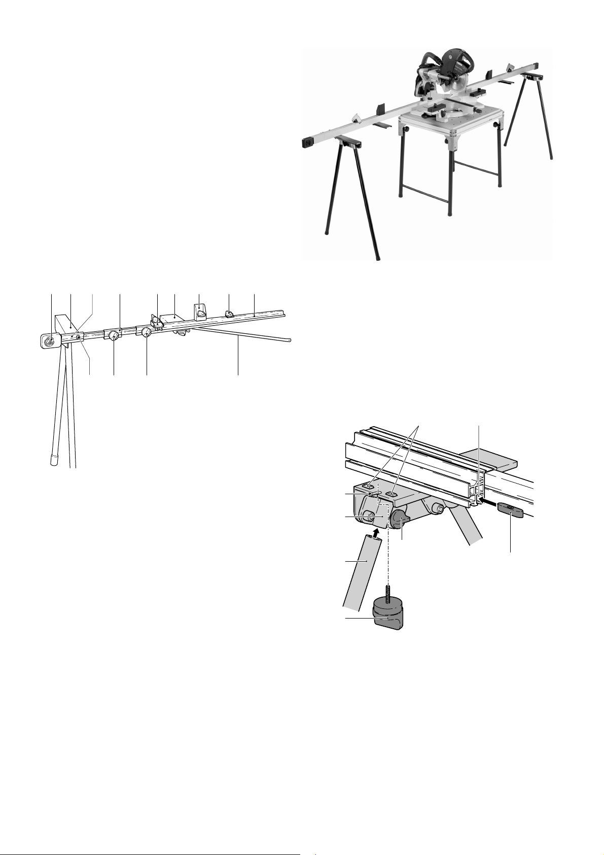
1 Scope of delivery
The trimming attachment consists of the
following main components:
(1.1) Stop profi le
(1.2) Tape measure clamp
(1.3) Support
(1.4) Support plate
(1.5) Stop fl ag
(1.6) Adjustable spacer
(1.7) Extendable end piece
(1.8) Leg support plate
(1.9) Tape measure
(1.13) Cross brace
1.9 1.7
1.6 1.4 1.31.8
1.5 1.2 1.1
2 x KA-KS 120
left
right
2.1 Preparations
– Secure the KS 120 to a Festool multifunc-
tion table (MFT) or a work bench with a
height of 31.1 in./790 mm (see operating
manual KS 120).
1.10
1.12
1.131.11
1
2 Set-up
When setting up the attachment, proceed in
the sequence specifi ed.
Important: you will require a crown moulding stop (AB-KS 120) to make the connection to the KS 120.
Refer to Figure 1 for the arrangement and
positioning of the individual parts.
Fig. 1 shows a rear view of the trimming
attachment.
The following section describes how to attach
the right trimming attachment. Use the
same procedure to attach the left trimming
attachment! Fig. 2 shows the stop mounted
on both sides!
2.2 Leg support plate
The leg support plate (1.8) is designed to
support the trimming attachment and is
fi xed to the extendable end piece (1.7).
3.6 3.7
3.5
3.4
3.1
3.3
3.2
3.8
3
– Unscrew both rotary knobs (3.1) until the
two support legs (3.3) can be inserted into
the clamping sleeves (3.4).
– Insert the support legs until the leg sup-
port plate reaches the same height as your
KS 120.
– Tighten the rotary knobs (3.1) to clamp
the support legs in place.
– Screw the rotary knob (3.2) through the
recess (3.5) and into the slot nut (3.8) in
the bottom slot (3.7) on the extendable
2
Page 3
end piece to secure the mounting plate.
Note: The two cams (3.6) must slot into
the groove (3.7).
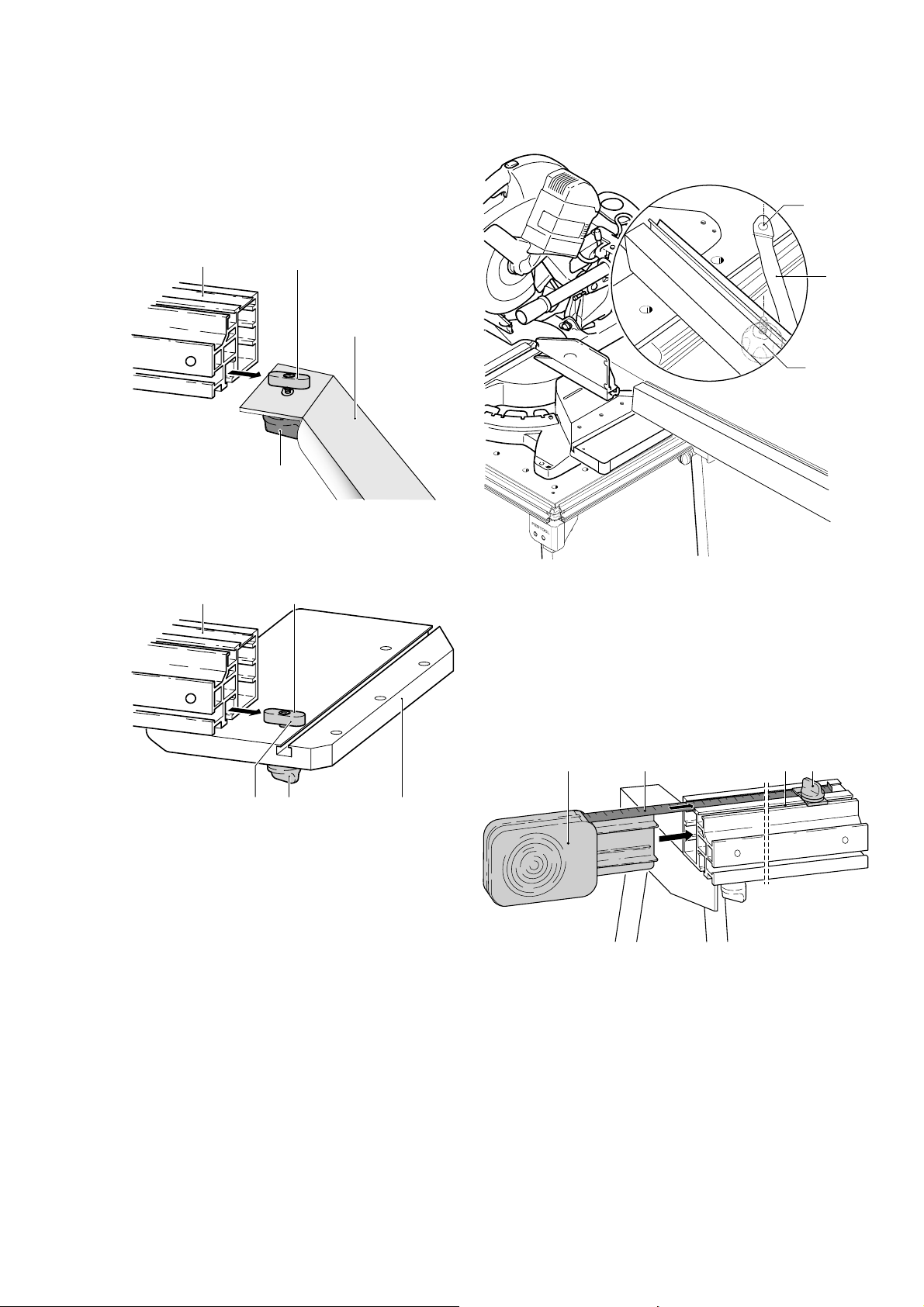
3.2 Cross brace
Secure the cross member (1.13) to the stop
profi le.
– Slide the slot nut (4.2) into the stop profi le
(4.1).
4.1
4.2
4.3
sembly instructions).
– Insert a clamp (6.3) in the hole (6.1) to
secure the cross brace (6.2) to the MFT.
Do not tighten yet!
6.1
6.2
6.3
4
4.4
2.4 Stop profi le
Secure the stop profi le to the bench for the
bracket support (AB-KS 120):
5.1 5.2
5.4 5.35.5
5
– Insert the rotary knob (5.4) through the
hole (5.5) in the bracket support bench and
secure the slot nut (5.2). Do not tighten
the knob yet – you must be able to lift the
slot nut approx. 0.2 in. above the bracket
support.
– Slide the stop profi le (5.1) onto the slot nut
(5.2) until the stop profi le is fl ush with the
edge of the bench (5.3).
– Fit the bracket support bench to the KS 120
(see bracket support assembly instructions).
– Align the bracket support bench so that
the stop profi le is fl ush with the stop ruler
on the KS 120. Clamp the bracket support
bench in place (see bracket support as-
6
–Use a long workpiece to align the trimming
attachment in relation to the compound
mitre saw.
– Tighten the rotary knob (5.4).
– Now tighten the connections on the cross
braces (4.4) and (6.3).
2.5 Tape measure, tape measure
clamp
7.2 7.3 7.47.1
7
– Insert the tape measure (7.1) into the
extendable end piece.
– Guide the tape measure (7.2) through the
top grooves on the extendable end piece,
the adjustable spacer and the stop profi le
in succession.
– Unscrew the rotary knob (7.4) for the tape
measure clamp.
– Insert the slot nut for the tape measure
clamp into the slot (7.3) on the stop pro-
fi le.
3
Page 4

– Secure the tape measure clamp towards
the end of the tape measure by tightening
the rotary knob (7.4).
2.6 Support plate
The support plate (1.4) is used to support
longer workpieces.
8.38.1 8.2
8.4
8.5
8
(9.2) on the stop profi le or the adjustable
spacer.
–If necessary, extend the telescopic section
of the trimming attachment 4 in. to insert
the support plate into the groove.
– Slide the support to the required positi-
on.
– Tighten the rotary knob (9.1) to secure the
support.
2.8 Stop fl ag
The stop fl ag (1.5) is used to adjust the
distance between the saw blade and the
workpiece so that the workpiece is cut to
the required length.
– Unscrew the rotary knob (1.11) on the
adjustable spacer.
– Move the stop profi le (1.1) and the spacer
(1.6) approx. 3.1 in. apart.
10.1 10.2
– Screw the rotary knob (8.5) through the
recess (8.4) and into the slot nut (8.1) in
the slot (8.2) on the stop profi le to secure
the support plate. Note: The two cams
(8.3) must slot into the groove (8.2).
–If necessary, extend the telescopic section
of the trimming attachment 4 in. to insert
the support plate into the groove.
2.7 Support
The support (1.3) is used to support taller
workpieces.
9.1 9.2
9
9.3
10
10.4
10.3
– Unscrew the rotary knob (10.1) that clamps
the stop fl ag.
– Insert the slot nut (10.3) into the top slot
(10.2) on the stop profi le or the adjustable
spacer.
– Slide the stop fl ag to the required positi-
on.
– Tighten the rotary knob (10.1) to secure
the stop fl ag.
Adjusting play on the stop fl ag
– Turn (tighten or unscrew) the two screws
(10.4) until the stop fl ag moves smoothly
along the slot, but without play.
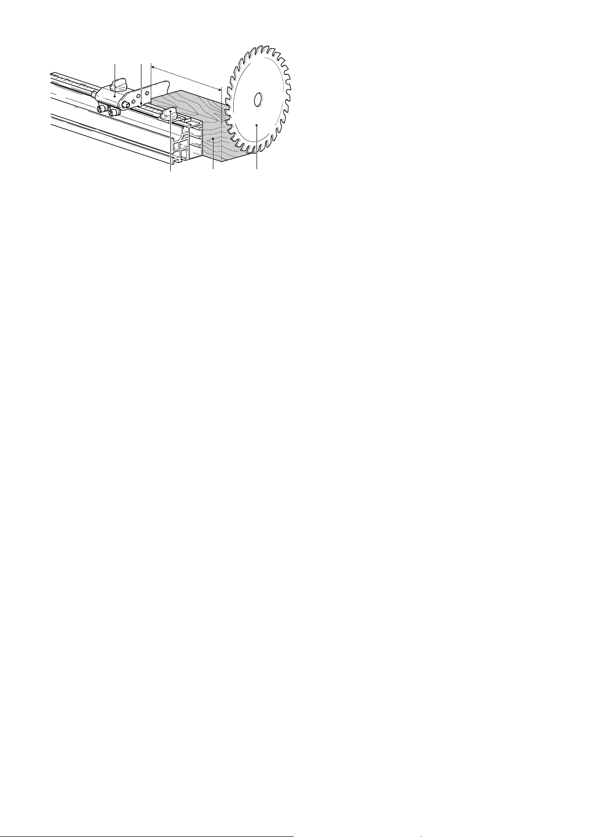
3 Adjustments
3.1 Tape measure
The tape measure starts at 11.81 in./
30 cm so that it does not come into contact with the saw blade. Therefore, make
sure that the distance between the tape
measure and the saw blade is correct:
– Unscrew the rotary knob (9.1) that clamps
the support.
– Insert the slot nut (9.3) into the top slot
4
Page 5
11.1 11.2
11
17.72 in.
11.5
11.4
11.3
– Set both the horizontal and vertical mitre
angles on the KS 120 to 0°.
– Place a workpiece (11.4) with a length
of 18.72 in./450 mm on the KS 120
lengthways against the saw blade (11.3).
– Slide the stop fl ag (11.1) up to the workpi-
ece. Clamp the stop fl ag in this position.
– Unscrew the rotary knob for the measuring
tape clamp (11.5).
– Move the tape measure until the measure-
ment at the edge (11.2) of the stop fl ag
indicates 18.72 in./450 mm.
– Use the tape measure clamp (11.5) to se-
cure the tape measure in this position. The
tape measure now indicates the exact dis-
tance to the saw blade. The measurement
at the edge (11.2) is the distance between
the stop fl ag and the saw blade.
3.2 Length adjustment
Unscrew the rotary knob (1.12) to extend and
retract the end piece (1.7). The maximum
extension length is 90.55 in./2300 mm.
Unscrew the rotary knob (1.11) to move
the spacer.
4 Working
To trim a workpiece to a certain length, proceed as follows:
– Adjust the stop fl ag to the required dimen-
sion.
– Place the workpiece against the stop
fl ag.
– Cut through the workpiece with the
KS 120.
5
Page 6

Guide butée KA-KS 120
1 Eléments fournis
Le guide butée comprend les éléments principaux suivants :
(1.1) Profi lé de butée
(1.2) Bloque-mètre
(1.3) Support
(1.4) Plaque d'appui
(1.5) Curseur de butée
(1.6) Pièce intermédiaire réglable
(1.7) Embout coulissant
(1.8) Support de pieds
(1.9) Mètre
(1.13) Renfort transversal
1.9 1.7
1.6 1.4 1.31.8
1.5 1.2 1.1
2 x KA-KS 120
gauche
droite
2.1 Opération préparatoire
– Fixez la KS 120 à une table multifonction
Festool (MFT) ou à une table de travail
d'une hauteur de 31.1 in./790 mm (voir
la notice d'utilisation de la KS 120).
1.10
1.12
1.131.11
1
2 Montage
Lors du montage, procédez dans l'ordre
indiqué.
Important : la butée inclinée (AB-KS 120)
est additionnellement nécessaire pour le
raccordement à l'unité KS 120.
Pour l'orientation et le positionnement des
pièces, reportez-vous à l'illustration 1.
La vue de la fi gure 1 correspond à la vue
de derrière.
Le paragraphe suivant décrit le montage du
guide-butée droit. Procédez de la même
manière pour le guide-butée gauche ! A des
fi ns de meilleure orientation, la butée est
représentée montée des deux côtés sur la
fi gure 2 !
2.2 Support de pieds
Le support de pieds (1.8) est fi xé à l'embout
coulissant (1.7) et sert d'appui pour le guide
butée.
3.6 3.7
3.5
3.4
3.1
3.3
3.2
3.8
3
– Dévissez les deux molettes (3.1) jusqu'à
ce que les deux pieds (3.3) puissent être
insérés dans les fi xations (3.4).
– Enfoncez les pieds jusqu'à ce le support
de pieds soit à la même hauteur que la
KS 120.
– Bloquez les pieds à l'aide des molettes
(3.1).
– Solidarisez la plaque de fi xation et l'embout
coulissant à l'aide de la molette (3.2) à
visser au niveau de l'encoche (3.5) et du
6
Page 7

coulisseau (3.8) à insérer dans la gorge
inférieure (3.7) de l'embout coulissant.
Attention : les deux ergots (3.6) doivent
s'enclencher dans la gorge (3.7).
2.3 Renfort transversal
Fixez le renfort transversal (1.13) sur le
profi lé de butée.
– Engagez le coulisseau (4.2) dans le profi lé
de butée (4.1).
4.1
4.2
4.3
la KS 120. Bloquez la tablette du support
d'angle (voir la notice de montage du sup-
port d'angle).
–Fixez le perçage (6.1) du renfort transversal
(6.2) à l'aide du dispositif de serrage (6.3)
de l'unité MFT. Ne pas encore serrer !
6.1
6.2
6.3
4
4.4
2.4 Profi lé de butée
Fixez le profi lé de butée à la tablette du
support d'angle (AB-KS 120) :
5.1 5.2
5.4 5.35.5
5
– Fixez le coulisseau (5.2) à l'aide de la
molette (5.4) au niveau du trou (5.5) de
la tablette du support d'angle. Ne serrez
pas encore ! Le coulisseau doit pouvoir
s'abaisser d'environ 0.2 in. par rapport au
support d'angle.
– Poussez le profi lé de butée (5.1) sur le
coulisseau (5.2) jusqu'à ce que le profi lé
de butée soit au même niveau que le chant
de la tablette (5.3).
– Montez la tablette du support d'angle sur
la KS 120 (voir la notice de montage de la
tablette du support d'angle).
– Orientez la tablette du support d'angle de
telle sorte que le profi lé de butée soit au
même niveau que la réglette de butée de
6
– Alignez à l'aide d'une pièce à travailler
longue le guide-butée par rapport à la scie
guidée.
– Serrez la molette (5.4).
–Serrez à présent les liaisons du renfort
transversal (4.4) et (6.3).
2.5 Mètre, bloque-mètre
7.2 7.3 7.47.1
7
– Positionnez le mètre (7.1) sur l'embout
coulissant.
– Déroulez le mètre (7.2) dans la gorge
supérieure de l'embout coulissant, de la
pièce intermédiaire réglable et du profi lé
de butée.
– Desserrez la molette (7.4) du bloque-mè-
tre.
– Insérez le coulisseau du bloque-mètre dans
7
Page 8

la gorge (7.3) du profi lé de butée.
– Bloquez le bloque-mètre à proximité de
l'enrouleur du mètre en serrant la molette
(7.4).
2.6 Plaque d'appui
La plaque d'appui (1.4) sert à soutenir les
pièces longues.
8.38.1 8.2
8.4
8.5
8
– Desserrez la molette (9.1) de fi xation du
support.
– Insérez le coulisseau (9.3) dans la gorge
supérieure (9.2) du profi lé de butée ou de
la pièce intermédiaire réglable.
–Ecartez le cas échéant l'élément télescopi-
que du guide-butée de 4 in., afi n de guider
la tôle-support dans la rainure.
– Amenez le support jusqu'à la position sou-
haitée.
– Fixez le support en vissant la molette
(9.1).
2.8 Curseur de butée
Le curseur de butée (1.5) permet de régler
la distance par rapport à la lame de scie et
donc la longueur de la pièce à scier.
– Desserrez la molette (1.11) de la pièce
intermédiaire réglable.
– Ecartez le profi lé de butée (1.1) et la pièce
intermédiaire (1.6) d'environ 3.1 in.
10.1 10.2
– Solidarisez la plaque d'appui et le profi lé de
butée à l'aide de la molette (8.5) à visser
au niveau de l'encoche (8.4) et du coulisseau (8.1) à insérer dans le gorge (8.2)
du profi lé de butée. Attention : les deux
ergots (8.3) doivent s'enclencher dans la
gorge (8.2).
–Ecartez le cas échéant l'élément télescopi-
que du guide-butée de 4 in., afi n de guider
la tôle-support dans la rainure.
2.7 Support
Le support (1.3) sert à soutenir les pièces
hautes.
9.1 9.2
10
10.4
10.3
– Desserrez la molette (10.1) de blocage du
curseur de butée.
– Insérez le coulisseau (10.3) dans la gorge
supérieure (10.2) du profi lé de butée ou
de la pièce intermédiaire réglable.
– Amenez le curseur de butée dans la posi-
tion souhaitée.
– Bloquez le curseur de butée en vissant la
molette (10.1).
Réglage du jeu du curseur de butée
– Vissez ou dévissez les deux vis (10.4) jus-
qu'à ce que le curseur de butée se déplace
sans jeu (mais librement) dans la gorge.
9
3 Réglages
3.1 Mètre
Afi n que le mètre ne puisse pas entrer en
contact avec la lame de scie, il commence
à 11.81 in./30 cm. Il est donc important de
régler correctement la distance par rapport
à la lame de scie :
9.3
8
Page 9

11.1 11.2
11
17.72 in.
11.5
11.4
11.3
– Réglez l'inclinaison de la KS 120 à 0° (ho-
rizontale et verticale).
– Positionnez une pièce (11.4) de 18.72
in./450 mm de long contre la lame de scie
(11.3) de la KS 120.
– Poussez le curseur de butée (11.1) contre
la pièce. Bloquez le curseur de butée dans
cette position.
– Desserrez la molette du bloque-mètre
(11.5).
– Décalez le mètre jusqu'à ce que le bord
(11.2) du curseur de butée indique la graduation 18.72 in./450 mm.
– Bloquez le mètre dans cette position à
l'aide du bloque-mètre (11.5). Le mètre
indique désormais le distance exacte par
rapport à la lame de scie. Le distance du
curseur de butée par rapport à la lame de
scie se lit au niveau du bord (11.2).
3.2 Réglage de la longueur
Une fois la molette (1.12) desserrée, il est
possible de sortir ou de rentrer l'embout
(1.7). La longueur maximale est de 90.55
in./2300 mm.
Une fois la molette (1.11) desserrée, il
est possible de déplacer la pièce intermédiaire.
4 Travail
Pour scier une pièce à la longueur voulue,
procédez comme suit :
– Réglez la longueur voulue à l'aide du cur-
seur de butée.
– Positionnez la pièce contre le curseur de
butée.
– Sciez la pièce avec la KS 120.
9
Page 10

Tope para tronzar KA-KS 120
1 Dotación de suministro
El tope para tronzar se compone principalmente de los siguientes elementos:
(1.1) Perfi l de tope
(1.2) Dispositivo de fi jación de la cinta
métrica
(1.3) Apoyo
(1.4) Chapa de apoyo
(1.5) Tope de apoyo
(1.6) Pieza intermedia ajustable
(1.7) Pieza fi nal extensible
(1.8) Soporte
(1.9) Cinta métrica
(1.13) Traviesa
1.9 1.7
1.6 1.4 1.31.8
1.5 1.2 1.1
2 x KA-KS 120
izquierda
derecha
2.1 Trabajos preliminares
– Fije la KS 120 a una mesa multifuncional de
Festool (MFT) o a una mesa de trabajo con
una altura de 31.1 in./790 mm (véase el
manual de instrucciones de la KS 120).
1.10
1.12
1.131.11
1
2 Estructura
Para el montaje de la estructura proceda en
la secuencia descrita a continuación.
Importante: para unir a la sierra de tronzar
KS 120 necesita adicionalmente el soporte
angular (AB-KS 120).
Preste atención a la imagen 1 con objeto
de llevar a cabo la alineación y el posicionamiento de las piezas sueltas.
La vista en la fi gura 1 se corresponde con la
vista desde la parte posterior.
A continuación de describe la estructura
del tope derecho para tronzar. Proceda de
forma análoga para montar el tope izquierdo
para tronzar. Para facilitar la orientación se
representa en la fi gura 2 el tope montado
en ambos lados.
2.2 Soporte
El soporte (1.8) sirve de apoyo para el tope
para tronzar y se sujeta con la pieza fi nal
extensible (1.7).
3.6 3.7
3.5
3.4
3.1
3.3
3.2
3.8
3
– Abra ambos botones giratorios (3.1) hasta
que las patas de apoyo (3.3) puedan introducirse en las abrazaderas de tubo (3.4).
– Introduzca las patas hasta que el soporte
quede a la misma altura que su KS 120.
– Inmovilice las patas de apoyo cerrando los
botones giratorios (3.1).
– Atornille fi rmemente la chapa de sujeción
en la entalladura (3.5) con el botón giratorio (3.2), así como la lengüeta insertada (3.8) en la ranura inferior (3.7) de la
10
Page 11

pieza fi nal extensible. Atención: los dos
salientes (3.6) han de quedar enclavados
en la ranura (3.7).
2.3 Traviesa
Fije la traviesa (1.13) al perfi l de tope.
–Deslice la lengüeta insertada (4.2) sobre
el perfi l de tope (4.1).
4.1
4.2
4.3
–Fije el taladro (6.1) de la traviesa (6.2)
con la sujeción (6.3) a la MFT. ¡No apriete
aún!
6.1
6.2
6.3
4
4.4
2.4 Perfi l de tope
Afi ance el perfi l de tope a la mesa de apoyo
angular (AB-KS 120) :
5.1 5.2
5.4 5.35.5
5
– Sujete la lengüeta insertada (5.2) con el
botón giratorio (5.4) en el taladro (5.5)
de la mesa de apoyo angular. No apriete
el botón hasta su tope: la lengüeta debe
poder separarse 0.2 in. aprox. del apoyo
angular.
– Deslice el perfi l de tope (5.1) por la len-
güeta insertada (5.2) hasta que quede
enrasado con el borde de la mesa (5.3).
– Monte la mesa de apoyo angular en la
KS 120 (véanse las instrucciones de montaje del apoyo angular).
– Regule la mesa de apoyo angular de tal
modo que el perfi l de tope quede enrasado
con la guía de tope de la KS 120. Inmovilice la mesa de apoyo angular (véanse
las instrucciones de montaje del apoyo
angular).
6
–Efectúe la alineación del tope para tronzar
y la sierra tronzadora con la ayuda de una
pieza de trabajo larga.
– Cierre el botón giratorio (5.4).
–Fije ahora las uniones de la traviesa (4.4)
y (6.3).
2.5 Cinta métrica, dispositivo de fi -
jación de la cinta métrica
7.2 7.3 7.47.1
7
– Coloque la cinta métrica (7.1) sobre la
pieza fi nal extensible.
– Desenrolle la cinta métrica (7.2) por las
ranuras superiores de la pieza fi nal exten-
sible, de la pieza intermedia ajustable y del
perfi l de tope.
– Abra el botón giratorio (7.4) del dispositivo
de fi jación de la cinta.
– Inserte la lengüeta del dispositivo de fi ja-
ción de la cinta en la ranura (7.3) del perfi l
de tope.
– Fije el dispositivo en la zona anterior a la
11
Page 12

cinta métrica cerrando el botón giratorio
(7.4).
2.6 Chapa de apoyo
La chapa de apoyo (1.4) actúa como apoyo
para piezas de trabajo de mayor longitud.
8.38.1 8.2
8.4
8.5
8
– Atornille fi rmemente la chapa de apoyo a
la entalladura (8.4) con el botón giratorio
(8.5) y el muelle de ajuste (8.1) a la ranura
(8.2) del perfi l de tope. Atención: los dos
salientes (8.3) han de quedar enclavados
en la ranura (8.2).
–En caso necesario, saque el telescopio del
tope para tronzar 4 in. para introducir la
chapa de apoyo en la ranura.
2.7 Apoyo
El apoyo (1.3) sirve, como su propio nombre indica, de apoyo para piezas de trabajo
más altas.
9.1 9.2
– Introduzca la lengüeta (9.3) en la ranura
superior (9.2) del perfi l de tope o de la
pieza intermedia ajustable.
–En caso necesario, saque el telescopio del
tope para tronzar 4 in. para introducir la
chapa de apoyo en la ranura.
– Desplace el apoyo hasta la posición desea-
da.
– Fije el apoyo cerrando el botón giratorio
(9.1).
2.8 Tope de apoyo
El tope de apoyo (1.5) permite ajustar la
distancia de separación con respecto a la
hoja de sierra y, por consiguiente, la longitud
de la pieza que vaya a serrarse.
– Abra el botón giratorio (1.11) de la pieza
intermedia ajustable.
– Desplace el perfi l de tope (1.1) y la pieza
intermedia (1.6) hasta dejar entre ellos
una separación de 3.1 in. aprox.
10.1 10.2
10
10.4
10.3
– Abra el botón giratorio (10.1) para la su-
jeción del tope de apoyo.
– Introduzca la lengüeta (10.3) en la ranura
superior (10.2) del perfi l de tope o de la
pieza intermedia ajustable.
– Desplace el tope de apoyo hasta la posición
deseada.
– Fije el tope de apoyo cerrando el botón
giratorio (10.1).
9
9.3
– Abra el botón giratorio (9.1) para la suje-
ción del apoyo.
Ajuste del juego del tope de apoyo
– Gire (abriendo o cerrando) ambos tornillos
(10.4) hasta que el tope de apoyo esté
exento de juego pero se pueda seguir moviendo con facilidad.
12
Page 13

3 Ajustes
3.1 Cinta métrica
11.1 11.2
11
17.72 in.
11.5
11.4
11.3
La cinta métrica parte de una medida de
11.81 in./30 cm para impedir que entre en
contacto con la hoja de sierra. Debe, por
tanto, ajustarse la distancia correcta entre
la cinta métrica y la hoja de sierra:
– Utilice para la KS 120 una escuadra de
inglete que forme un ángulo de 0° con los
planos horizontal y vertical.
– Coloque la pieza de trabajo (11.4) de una
longitud de 18.72 in./450 mm transversal
con respecto a la hoja de sierra (11.3) de
la KS 120.
– Aproxime el tope de apoyo (11.1) hasta
la pieza de trabajo. Inmovilice el tope de
apoyo en esta posición.
– Abra el botón giratorio (11.5) del disposi-
tivo de fi jación de la cinta métrica.
– Desplace la cinta métrica hasta que el
borde (11.2) del tope de apoyo coincida
con la marca de medida de 18.72 in./
450 mm.
– Sujete la cinta métrica en esta posición
con el dispositivo de fi jación (11.5). La
cinta métrica marca ahora la distancia ex-
acta con respecto a la hoja de sierra. En
el borde (11.2) podrá ver la distancia de
separación entre el tope de apoyo y la hoja
de sierra.
3.2 Ajuste de longitud
Con el botón giratorio (1.12) abierto es posible extender y retraer la pieza fi nal (1.7).
La máxima extensión que alcanza es de
90.55 in./2300 mm.
Con el botón giratorio (1.11) abierto es posible desplazar la pieza intermedia.
4 Trabajos
Para tronzar una pieza de trabajo a una
longitud determinada, proceda como se
describe a continuación:
– Ajuste la medida deseada en el tope de
apoyo.
– Coloque la pieza de trabajo pegada al tope
de apoyo.
– Sierre la pieza con la KS 120.
13
Page 14

Page 15

Page 16

 Loading...