

Page 1

Festool Group GmbH & Co. KG
Wertstraße 20
D-73240 Wendlingen
Tel.: +49 (0)7024/804-0
Telefax: +49 (0)7024/804-20608
www.festool.com
705074_005
Instruction manual
Page 6
IMPORTANT: Read all instructions before using.
Guide d’utilisation
Page 21
IMPORTANT: Lire toutes les instructions avant de démarrer les travaux.
Manual de instrucciones
Página 36
IMPORTANTE: Lea todas las instrucciones antes de usar.
Instruction manual
Guide d’utilisation
Manual de instrucciones
KA 65
Page 2

Page 3

Page 4
1
1-1
1-2
1-4
1-5
1-6
1-7
1-8
1-9
1-10
1-11
1-13
1-14
1-15
1-17
1-18
33,0 m
130 190 °C
MODE
OK
2
1-21
1-19
1-20
1-12
1-3
1-16
Page 5

Page 6
6
Contents
Symbols
Symbols................................................ 6
Safety instructions............................... 7
Technical data...................................... 9
Functional description......................... 9
Intended use ........................................ 10
Operation.............................................. 10
Settings................................................. 11
Working with the machine.................... 13
Service and maintenance..................... 16
Accessories .......................................... 17
Environment ......................................... 18
Warranty............................................... 18
Troubleshooting.................................... 19
Vvolts
A amperes
Hz hertz
~
a.c.
alternating current
d.c.
direct current
n
0
no load speed
Class II construction
rpm
min
-1
revolutions per minute
’’ inch
lb. pound
diameter
hint, tipp
Burning risks from hot surfaces!
Warning of general danger
Risk of electric shock
Read the Operating Instructions/Notes!
Wear a dust mask.
Wear protective gloves.
Wear protective goggles.
CAUTION. Danger of crushing fingers!
Do not throw in the household waste.
Tip or advice
Handling instruction
°C degree centigrade
°F degree Fahrenheit
Nm Newton metre
mm millimetre
Ah amps hour
Wh watt hour
delay fuse with 4 amps
Page 7

7
Safety instructions
General safety instructions
WARNING! Read all safety warnings and all
instructions.
Failure to follow the warnings
and instructions may result in electric shock, fire
and/or serious injury.
Save all warnings and instructions for future reference.
The term “power tool” in the warnings refers to
your mains-operated (corded) power tool or battery-operated (cordless) power tool.
1 WORK AREA SAFETY
a.
Keep work area clean and well lit.
Cluttered and
dark areas invite accidents.
b.
Do not operate power tools in explosive atmospheres, such as in the presence of flammable
liquids, gases or dust.
Power tools create sparks
which may ignite the dust or fumes.
c.
Keep children and bystanders away while operating a power tool.
Distractions can cause you to
lose control.
2 ELECTRICAL SAFETY
a.
Power tool plugs must match the outlet. Never
modify the plug in any way. Do not use any
adapter plugs with earthed (grounded) power
tools.
Unmodified plugs and matching outlets
will reduce risk of electric shock.
b.
Avoid body contact with earthed or grounded
surfaces, such as pipes, radiators, ranges and
refrigerators.
There is an increased risk of elec-
tric shock if your body is earthed or grounded.
c.
Do not expose power tools to rain or wet conditions.
Water entering a power tool will increase
the risk of electric shock.
d.
Do not abuse the cord. Never use the cord for
carrying, pulling or unplugging the power tool.
Keep cord away from heat, oil, sharp edges or
moving parts.
Damaged or entangled cords in-
crease the risk of electric shock.
e.
When operating a power tool outdoors, use an
extension cord suitable for outdoor use.
Use of
a cord suitable for outdoor use reduces the risk of
electric shock.
f.
If operating a power tool in a damp location is
unavoidable, use a residual current device
(RCD) protected supply.
Use of an RCD reduces
the risk of electric shock.
3 PERSONAL SAFETY
a.
Stay alert, watch what you are doing and use
common sense when operating a power tool. Do
not use a power tool while you are tired or under
the influence of drugs, alcohol or medication.
A
moment of inattention while operating power
tools may result in serious personal injury.
b.
Use personal protective equipment. Always
wear eye protection.
Protective equipment such
as dust mask, non skid safety shoes, hard hat, or
hearing protection used for appropriate conditions will reduce personal injuries.
c.
Prevent unintentional starting. Ensure the
switch is in the off-position before connecting to
power source and/or battery pack, picking up or
carrying the tool.
Carrying power tools with your
finger on the switch or energising power tools
that have the switch on invites accidents.
d.
Remove any adjusting key or wrench before
turning the power tool on.
A wrench or a key left
attached to a rotating part of the power tool may
result in personal injury.
e.
Do not overreach. Keep proper footing and balance at all times.
This enables better control of
the power tool in unexpected situations.
f.
Dress properly. Do not wear loose clothing or
jewellery. Keep your hair, clothing and gloves
away from moving parts.
Loose clothes, jewel-
lery or long hair can be caught in moving parts.
g.
If devices are provided for the connection of
dust extraction and collection facilities, ensure
these are connected and properly used.
Use of
dust collection can reduce dust-related hazards.
h.
Do not let familiarity gained from freuquent use
of tools allow you to become complacent and ignore, tool safety principles.
A careless action
can cause severe injury within a fraction of a second.
4 POWER TOOL USE AND CARE
a.
Do not force the power tool. Use the correct
power tool for your application.
The correct
power tool will do the job better and safer at the
rate for which it was designed.
b.
Do not use the power tool if the switch does not
turn it on and off.
Any power tool that cannot be
controlled with the switch is dangerous and must
be repaired.
c.
Disconnect the plug from the power source and/
or battery pack from the power tool before
Page 8

8
making any adjustments, changing accessories,
or storing power tools.
Such preventive safety
measures reduce the risk of starting the power
tool accidentally.
d.
Store idle power tools out of the reach of children and do not allow persons unfamiliar with
the power tool or these instructions to operate
the power tool.
Power tools are dangerous in the
hands of untrained users.
e.
Maintain power tools. Check for misalignment
or binding of moving parts, breakage of parts
and any other condition that may affect the power tool‘s operation. If damaged, have the power
tool repaired before use.
Many accidents are
caused by poorly maintained power tools.
f.
Keep cutting tools sharp and clean.
Properly
maintained cutting tools with sharp cutting edges
are less likely to bind and are easier to control.
g.
Use the power tool, accessories and tool bits
etc. in accordance with these instructions taking into account the working conditions and the
work to be performed.
Use of the power tool for
operations different from those intended could
result in a hazardous situation.
h.
Keep handles dry, clean and free from oil and
grease.
Slippery handles do not allow for safe
handling and control of the tool in unexpected
situations.
5 SERVICE
a.
Have your power tool serviced by a qualified repair person using only identical replacement
parts.
This will ensure that the safety of the pow-
er tool is maintained.
Machine-related safety instructions
–
Always hold the machine by the insulated handles because the heating unit and adhesive nozzle can become very hot. Risk of burns!
–
Always use the machine in well-ventilated
rooms.
Otherwise there is a risk that excessive
quantities of vapour will develop during work.
–
Do not use the machine for overhead work.
When performing overhead work, there is a danger of hot liquid adhesive dripping on the machine operator.
–
Protect the machine from moisture.
Moisture
can cause electric shocks.
–
Protect the cable from heat sources, oil and
sharp edges and keep away from hot machine
components.
Damage to the cable can cause
electric shocks.
–
Check the plug and the cable regularly to avoid
hazards and have them replaced by an authorised after-sales service workshop if they become damaged.
A defective plug or cable can
cause electric shocks.
–
Do not pull the plug from the socket by the cable.
The plug or cable may become damaged and
cause electric shocks.
–
Always use an extension cable with protective
earth conductor.
If an extension cable is used
without a protective earth conductor, the machine's electrical system is no longer protected,
which can cause electric shocks.
–
CAUTION: To provide continued protection
against risk of electric shock, connect to properly grounded outlets only.
–
Always remove melted adhesive cartridges by
purging.
Adhesive cartridges that are not melted
can be removed by hand.
–
Wear suitable personal protective equipment:
dust mask for reducing the risk of inhaling hazardous vapours, protective gloves for handling
hot machine components, safety goggles.
–
The Festool edge bander should always be
mounted on work benches using the stationary
fixture supplied by Festool.
The electric power
tool may become unsafe and cause serious accidents if installed in benches from other manufacturers or self-manufactured work benches.
–
Always use original Festool accessories and adhesive cartridges.
Only products tested and approved by Festool are harmless to health and
perfectly adapted to the machine and application.
Please refer to the safety data sheet for additional specifications. See Festool catalogue or
www.festool.com.
–
Observe national safety regulations!
Health hazard by dust
WARNING!
Various dust created by power
sanding, sawing, grinding, drilling and other
construction activities contains chemicals
known (to the State of California) to cause cancer,
birth defects or other reproductive harm. Some examples of these chemicals are:
• lead from lead-based paints,
• crystalline silica from bricks and cement and
other masonry products, and
• arsenic and chromium from chemicallytreated
lumber.
Page 9

9
The risk from these exposures
varies, depending on how often
you do this type of work. To reduce your exposure to these
chemicals: work in a well ventilated area, and work with ap-
proved safety equipment, such as dust masks that
are specially designed to filter out microscopic particles. Wash hands after handling.
Technical data
*
Depending on material
Functional description
The pictures for the functional description are on a
fold-out page at the beginning of the instruction
manual. When reading of the manual you can fold
out this page for having always an overview of the
machine.
WARNING
TO REDUCE THE RISK OF INJURY, USER MUST
READ INSTRUCTION MANUAL.
Edge bander KA 65
Power 1050 W
Power supply 120 V~
Mains frequency 60 Hz
Edge height 18 - 65 mm (0.7 - 2.6’’)
*
Edge thickness 0.5 - 3.0 mm (0.02 - 0.1’’)
*
Inner radius > 50 mm (2.0’’)
*
Heating time approx. 8 min
Default melting temperature setting Setting 1 190 °C
Setting 2 200 °C
Melting temperature setting range Setting 1/2 100 - 210 °C
Feed speed 1st gear 2 m/min
2nd gear 4 m/min
Safety class I
Weight (without adhesive cartridges and mains cable) 7.9 kg (17.4 lbs)
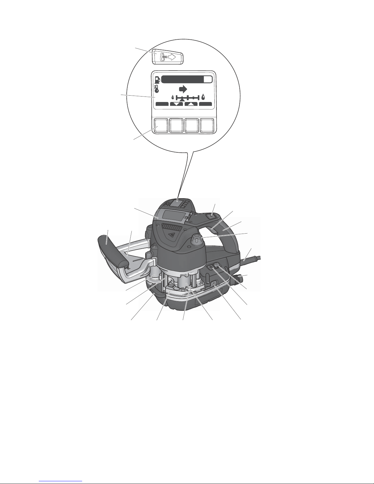
[1-1]
Start button
[1-2]
Feed speed button
[1-3]
Handle
[1-4]
Rotary knob for adjusting the edge
height
[1-5]
Mains power cable
[1-6]
Extractor connector
[1-7]
Switch for temperature selection
[1-8]
On/Off switch
[1-9]
Safety lever for purging
[1-10]
Inlet roller
[1-11]
Edge inlet
[1-12]
Central plate
[1-13]
Drip catcher
[1-14]
Adhesive nozzle
[1-15]
Contact roller
[1-16]
Handle
[1-17]
Support base with start marking
[1-18]
Flap
[1-19]
Menu buttons
[1-20]
Display
[1-21]
Refill button
Page 10
10
Accessories shown or described are sometimes not
included in the scope of delivery.
Intended use
The edge bander is suitable for:
– Attaching edge bands made of wood, materials
similar to wood and plastic using
Festool adhe-
sives
.
Operation
Initial operation
Remove protective foil from underneath the
support base
[1-17]
and display
[1-20]
.
The machine may generate large quantities
of smoke and a pungent odour when operated for the first time.
Do not use the machine and working materials below 15 °C. Recommendation: room
temperature.
Preparing for operation
Install the support base
[2]
.
Insert the plug into an earthed socket.
Insert a minimum of two adhesive cartridges in
the magazine
(chapter Refilling an adhesive
cartridge [6])
.
Set the heating temperature for the relevant adhesive cartridges.
Temperature selection
[1-7]
according to the de-
fault setting:
Setting 1 = 190 °C
Setting 2 = 200 °C
The temperature can be adjusted by pressing
the menu buttons
[1-19] (chapter Menu but-
tons [1-19])
. After independent changes are
WARNING
The user bears the responsibility for damage and
accidents caused by improper use; this also includes damage and wear caused by continuous
use in industry.
WARNING
Unauthorised voltage or frequency!
Risk of accident
The mains voltage and the frequency of the power source must correspond with the specifications on the machine's name plate.
In North America, only Festool machines with
the voltage specifications 120 V/60 Hz may be
used.
2
– – – –
2
1
2
1
2-1
Page 11
11
made, the last temperature used is automatically
saved to the selected setting and replaces the default setting.
Switching on
Press the on/off switch
[1-8]
once and hold until
the Festool logo appears on the display
[1-20]
.
The machine increases the temperature in heating
mode until the setpoint temperature is reached
(display
[1-20]
lights up red).
Machine switches to warming phase (display
[1-20]
flashes red/green).
Machine is ready for operation (display
[1-20]
lights
up green).
Switching off
Press the on/off switch
[1-8]
< 1 s
The machine reduces the temperature in cooling
mode and then switches off.
Display
[1-20]
lights up red, fan symbol is dis-
played.
Press the on/off switch
[1-8]
and hold > 1 s
The machine switches off immediately.
Settings
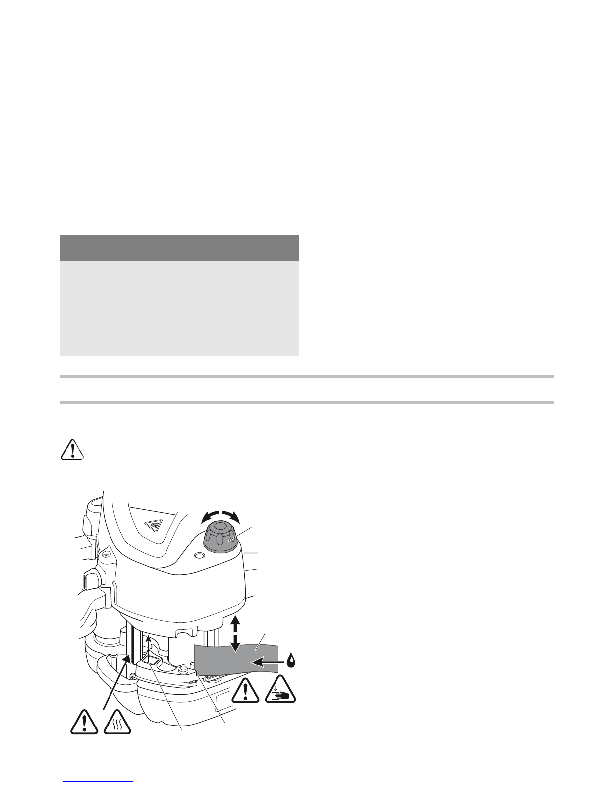
Adjusting the edge height [3]
The edge height can only be adjusted
at op-
erating temperature
! Ignoring this instruc-
tion may result in machine damage.
Guide the edge band
[3-2]
into the edge inlet
[3-
3]
.
Use the rotary knob
[3-1]
to adjust the height of
the edge inlet
[3-3]
until the edge band
[3-2]
rests against the top and bottom of the inlet.
Turn back the rotary knob by one locking position so that the edge band
[3-2]
can slide
through smoothly without becoming caught.
Adapting the adhesive quantity
The necessary adhesive quantity is automatically
adjusted to the current edge height.
Press the menu buttons
[1-19]
to adapt the adhesive quantity (layer thickness) to different workpiece materials
(chapter Menu buttons [1-19])
.
NOTE
Do not leave the machine unattended!
When taking a break of less than 15 minutes,
switch the machine to cooling mode (chapter
Switching off).
When taking a longer break, switch off the machine completely.
3
3-3
3-1
3-4
-
+
+
-
3-2
Page 12
12
Selecting the feed speed
The feed speed can be adjusted and adapted to the
contour of the workpiece at any time by pressing
the button
[1-2]
.
1st gear = 2 m/min
2nd gear = 4 m/min
Menu buttons [1-19]
The following settings can be modified using the
menu buttons
[1-19]
:
– Adhesive quantity
– Setpoint temperature
– Units of measurement
If no menu buttons are pressed within 10
seconds, the menu is closed automatically
and the changes are discarded.
Display [1-20]
The current settings and information graphics are
shown on the display
[1-20]
.
Mode button
Press the button to select the
value you wish to change
(flashes).
Arrow buttons
The selected value can be
adjusted.
OK
Press <OK> to save any
changes.
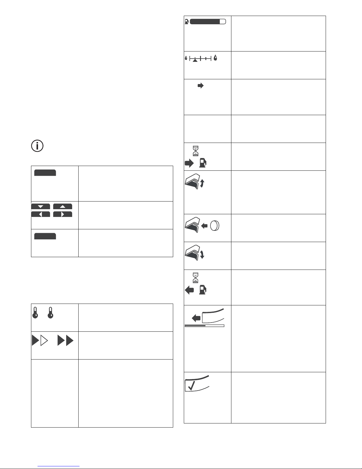
Temperature selection [1-7]
Setting 1 (190 °C) / Setting 2
(200 °C)
Feed speed[1-2]
1st gear (2 m/min) / 2nd gear (4
m/min)
Units of measurement
Select from °C/m, °C/ft, °F/ft or
°F/m.
°C = degrees Celsius
m = metres
°F = degrees Fahrenheit
ft = feet
MODE
OK
2
1
°C/m, °C/ft, °F/ft, °F/m
Remaining edge length
**
Edge band length in relation to
the remaining quantity of adhesive.
Adhesive quantity
Setting for the required adhesive quantity.
Actual and setpoint temperature
Display
[1-20]
lights up red
during heating mode.
Setpoint temperature
Ready for operation, display
[1-
20]
lights up green.
Refill button [1-21]pressed
Adhesive feed is reversed for
refill process.
Open flap [1-18]
Adhesive feed was reversed for
refill process. Flap
[1-18]
can
be opened.
Insert adhesive cartridges
The magazine can be refilled
with adhesive cartridges.
Close the flap [1-18]
Work can continue after the flap
[1-18]
is closed.
Refill process complete
Adhesive feed moves forward
and pressure builds in the
adhesive cartridges.
Edge inlet ready
Guide the edge band into the
edge inlet
[1-11]
within 20 seconds. The remaining time is displayed. If the edge band is not
inserted within the specified
time, the start button
[1-1]
must be pressed again.
Edge band to start position
Now press the start button
[1-1]
to glue the edge band. The
inlet starts up and transports
the edge band through the
machine.
33,0 m
130 190 °C
190 °C
Page 13
13
**
Automatic calculation of currently detected edge
height
Dust extraction
An extractor hose with a diameter of 27 mm can be
attached to the extractor connector
[1-6]
.
Working with the machine
Remove the edge band
An edge band was detected
when the machine was switched
on. Request for removal of the
edge band. Press the start button
[1-1]
and hold until the edge
band has passed through.
Purging position reached
Central plate
[1-12]
has been
lowered completely and moved
to purging position.
Purging process starts
Start button
[1-1]
was pressed.
The purging process starts after
one second.
Purging process is carried out
Adhesive nozzles are open,
pressure has built in the adhesive cartridges. Display of the
current status.
Cooling mode
The machine reduces the temperature in cooling mode and
then switches off. Cooling mode
is activated when:
–on/off switch
[1-8]
is pressed <
1 s
–no controls are actuated for
more than 15 minutes
The machine is switched on
again by pressing the start button
[1-1]
or the on/off switch
[1-8]
.
190 °C
2
MODE
190 °C
2
180 °C
Fault symbol
Troubleshooting
(chapter Trou-
bleshooting)
.
CAUTION
Vapours emitted during the glueing process!
Ensure there is good ventilation.
Use an extractor.
Always observe national regulations.
0
WARNING
High temperatures on the heating unit and adhesive nozzle!
Risk of burns when touched
Wear suitable protective gloves.
Always hold the machine by the insulated handles
[1-3], [1-16]
!
WARNING
Moving workpiece!
Risk of injury from sliding workpiece
Always secure the workpiece in such a manner
that it cannot move.
Page 14
14
Glueing the edge band
Cut the edge band down to size, leaving an allowance of approximately 10 cm.
Switch on the machine
[1-8]
.
Select the temperature setting
[1-7]
.
Display
[1-20]
lights up red = actual and setpoint temperature are displayed. Machine is not
yet ready for operation.
Display
[1-20]
lights up green = operating temperature reached. Setpoint temperature is displayed.
Machine is now ready for operation.
Adjust the relevant settings
(chapter Settings)
.
Press the start button
[1-1]
once.
Edge inlet mechanism starts up.
Guide the edge band into the edge inlet within 20
seconds
[1-11]
.
The time remaining is shown on the display
[1-
20]
.
The edge band is drawn in automatically up to
the light barrier
[3-4]
.
Inlet stops.
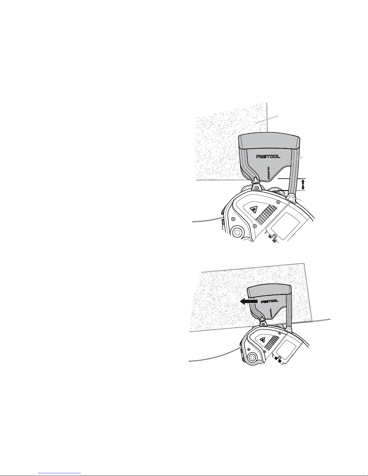
Position the machine on the workpiece
[4-1]
approx. 2 cm away from the contact roller
[4-3]
with reference to the start marking
[4-2] [4]
.
The start marking
[4-2]
and edge of the work-
piece must be flush with one another.
Press the start button
[1-1]
again.
Inlet starts.
Wait until the edge band with adhesive is visible.
Push the machine down onto the workpiece and
guide lengthways from right to left
[5]
. Exert
pressure on the support base and against the
workpiece. Applying pressure in the feed direction is not necessary.
The edge feed mechanism moves the machine
forwards automatically.
Once the edge band has passed through the
feed completely, the mechanism stops automatically after a short delay.
4
4
4-2
4-3
4-1
0,79 inch
5
Page 15
15
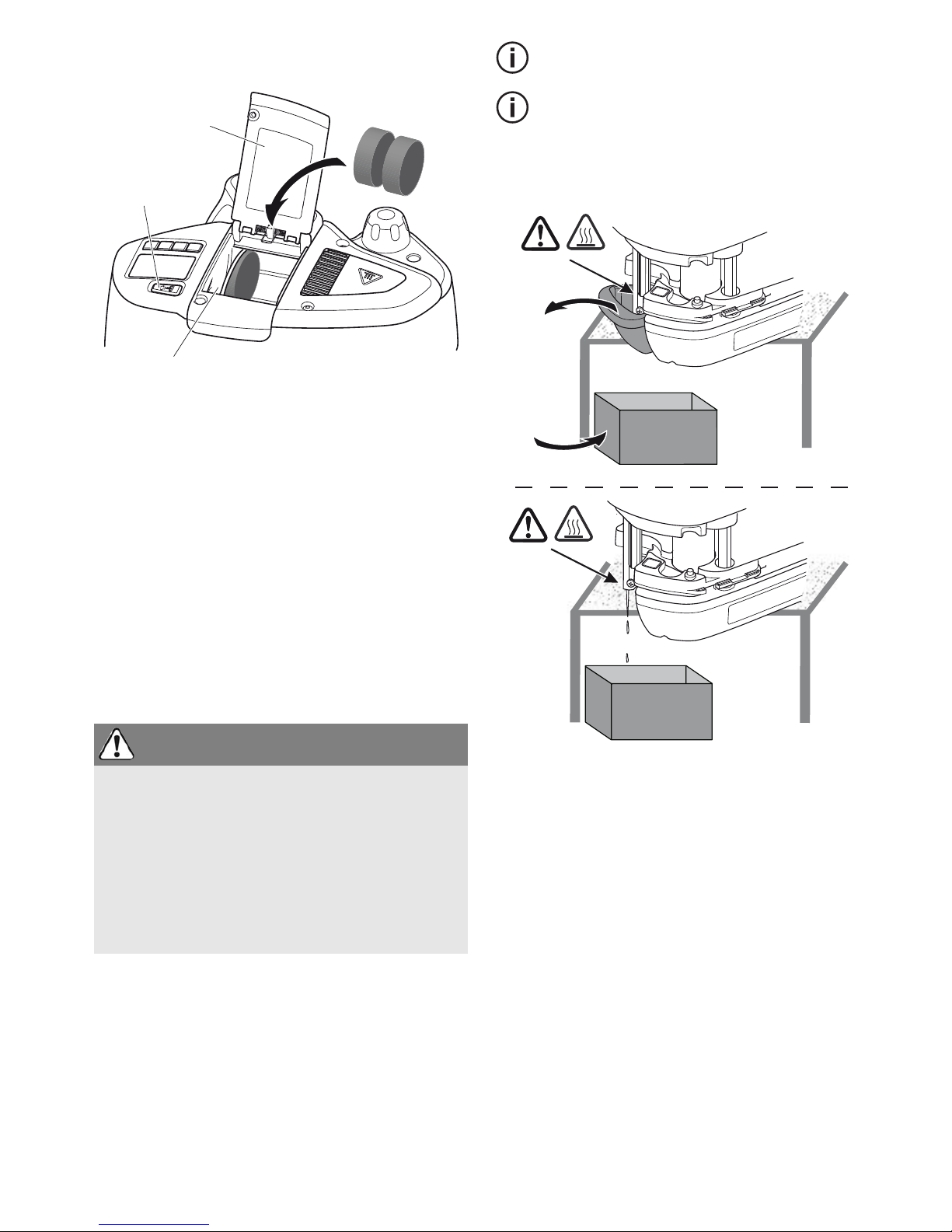
Refilling an adhesive cartridge [6]
Press the refill button
[6-1]
.
Adhesive feed
[6-2]
moves back.
Open the flap
[6-3]
.
Insert adhesive cartridges in the magazine.
Close the flap
[6-3]
.
Wait until the adhesive feed
[6-2]
mechanism
has moved forward and pressure has built up in
the adhesive cartridges.
The refill process is complete, machine operation
can resume.
Purging of adhesive cartridges
Adhesive is pressed through the system without an
edge band present when:
– The colour of adhesive cartridges is changed
Approximately three adhesive cartridge are
required to purge the machine completely.
If necessary, press the refill button
[1-21]
for
other adhesive cartridges and repeat the
procedure.
Position the machine at the edge of the bench
[7]
.
Remove the drop catcher
[1-13]
.
Place the container for catching hot adhesive
into position.
Press the refill button
[1-21]
.
Adhesive feed moves back.
Open the flap
[1-18]
.
Remove all the adhesive cartridges.
Insert new adhesive cartridges.
Close the flap
[1-18]
.
Set the edge height to maximum using the rotary knob for adjusting the edge height
[1-4]
.
Actuate the safety lever for purging the machine
[1-9]
while simultaneously turning the rotary
knob for adjusting the edge height
[1-4]
clock-
WARNING
Adhesive may escape immediately after actuating the safety lever [1-8] and simultaneously lowering the central plate [1-12] (purging position)!
Risk of burns, damage to property from hot adhesive
Remove the drop catcher and place a larger container such as a cardboard box under the machine.
6
6-1
6-2
6-3
7
Page 16

16
wise until the central plate
[1-12]
rests against
the bottom of the machine.
Purge position is reached.
Press the start button
[1-1]
and hold > 1 s.
The purging preparation symbol appears on the
display
[1-20]
. The process starts after 1 s.
Continue purging until new adhesive appears in
the adhesive nozzle
[1-14]
.
Adhesive nozzles are open, pressure has built in
the adhesive cartridges.
The purging symbol appears on the display
[1-
20]
together with a status indicator.
Interrupt purging: press the start button
[1-1]
again.
Adhesive nozzles are open, pressure stops
building in the adhesive cartridges.
Stop purging and leave purging position: turn
the rotary knob for adjusting the edge height
[1-
4]
clockwise.
Central plate moves upwards, adhesive nozzles
are closed, pressure stops building in adhesive
cartridges. Display
[1-20]
indicates normal
standby status.
Insert the drop catcher
[1-13]
again.
After finishing work
Switch off the machine and allow to cool.
If necessary, clean the adhesive nozzle
[1-14]
carefully using a strip of wood. Do not use metallic or highly flammable materials!
Remove the drip catcher
[1-13]
and turn upside
down to clean.
Observe the following instructions:
–Allow the
machine to cool completely
before
placing in a Systainer.
– Do not transport the machine in purging mode
otherwise adhesive may escape.
Service and maintenance
Always keep the machine clean. Read
chapter
Purging of adhesive cartridges
and
After fin-
ishing work
!
If the plastic sliding plate
[2-1]
(wear part) is
damaged, the plate can be replaced by loosening the 4 screws underneath the support base
[1-17]
.
Keep the ventilation slits on the electric power
tool clean and unobstructed to guarantee adequate cooling.
Store in a cool location that is free of dust.
WARNING
Any maintenance or repair work that requires
opening of the motor or gear housing should only
be carried out by an authorised Customer Service
Centre (name supplied by your dealer)!
Maintenance or repair work carried out by an
unauthorised person can lead to the wrong connection of the power cord or other components,
which in turn can lead to accidents with serious
consequences.
WARNING
To prevent accidents, always remove the plug
from the power supply socket before carrying out
any maintenance or repair work on the tool!
Do not use compressed air to clean the electrical
tool! Do not try to clean parts inside the tool in
this way, as you could let foreign objects in
through the openings of the tool housing.
CAUTION
Certain cleaning agents and solvents are harmful
to plastic parts.
Some of these include, but are not limited to:
Gasoline, Acetone, Methyl Ethyl Ketone (MEK),
Carbonyl Chloride, cleaning solutions containing
Chlorine, Ammonia, and household cleaners
containing Ammonia.
Page 17

17
Customer service and repair
only
through manufacturer or service
workshops: Please find the nearest
address at:
www.festoolusa.com/service
Use only original Festool spare parts!
Order No. at:
www.festoolusa.com/service
Accessories
Use only original Festool accessories and Festool
consumable material intended for this machine because these components are designed specifically
for the machine. Using accessories and consumable material from other suppliers will most likely
affect the quality of your working results and limit
any warranty claims. Machine wear or your own
personal workload may increase depending on the
application. Protect yourself and your machine, and
preserve your warranty claims by always using
original Festool accessories and Festool consumable material!
The order numbers of the accessories and tools can
be found in the Festool catalogue or on the Internet
under "www.festoolusa.com".
Systainer
Many Festool products are shipped in a unique system container, called "Systainer". This provides
protection and storage for the tool and accessories.
The Systainers are stackable and can be interlocked together. They also can be interlocked atop
Festool CT dust extractors.
To open the Systainer
To lock the Systainer
To connect two Systainers
Place one Systainer on the top of the other (Fig.
[8A]
).
The Systainers are connected and locked.
A new generation Systainer is connectable on
top of a previous generation Systainer by the
four latches of the previous Systainer.
EKAT
1
2
3
5
4
Turn the T-loc
[8-1]
to this position.
Turn the T-loc
[8-1]
to this position.
Turn the T-loc
[8-1]
to one of this posi-
tions (Fig.
[8B]
).
open
lock
connect
connect
T-loc
8-1
A
8
B
Page 18

18
Environment
Do not dispose of the device together with domestic waste!
Dispose of machines, accessories and
packaging at an environmentally responsible recycling centre. Observe the valid national regulations.
Warranty
Garantie 1 + 2
Festool offers a 3 year limited warranty, one of the
strongest in the industry. This warranty is valid on
the pre-condition that the tool is used and operated
in compliance with the Festool operating instructions. Festool warrants that the specified tool will
be free from defects in materials and workmanship
for a term of 3 years from the date of purchase.
Conditions of 1 + 2 warranty
All customers receive a free extended limited warranty (1 year + 2 years = 3 Years) on new Festool
power tools purchased from an authorized retailer.
Festool is responsible for all shipping costs during
the first year of the warranty. During the second
and third year of the warranty the customer is responsible for shipping the tool to Festool. Festool
will pay for return shipping to the customer using
UPS Ground Service. All warranty service is valid 3
years from the date of purchase on your receipt or
invoice. Proof of purchase may be required.
Excluded from the coverage under this warranty
are:
normal wear and tear, damages caused by
misuse, abuse, or neglect; damage caused by anything other than defects in material and workmanship. This warranty does not apply to accessory
items such as circular saw blades, drill bits, router
bits, jigsaw blades, sanding belts, and grinding
wheels. Operating a tool at a voltage or frequency
different from the tool's rating will void the warranty. This includes the usage of the tool in combination with a transformer. Festool does not condone
nor support the use of any non-Festool engineered,
designed, and manufactured accessories or consumables with Festool products. Use of any nonFestool products may affect performance or void
the warranty. Festool is not responsible for any
damages or losses incurred and user assumes all
risk and responsibility with non-Festool derived
products. Also excluded are "wearing parts," such
as carbon brushes, lamellas of air tools, rubber
collars and seals, sanding discs and pads, and Festool gear (hats and shirts).
The obligations of Festool in its sole discretion under this warranty shall be limited to repair or replacement or a refund of the purchase price for any
Festool portable power tool that is found to have a
defect in materials or workmanship during the warranty period. FESTOOL SHALL NOT BE LIABLE FOR
ANY CONSEQUENTIAL, INCIDENTAL OR SPECIAL
DAMAGES REGARDLESS OF THE THEORY OF LAW
ON WHICH THE CLAIM IS BASED. ALL WARRANTIES IMPLIED BY STATE LAW, INCLUDING THE IMPLIED WARRANTIES OR MERCHANTABILITY AND
FITNESS FOR A PARTICULAR PURPOSE ARE HEREBY LIMITED TO THE DURATION OF THREE YEARS.
Some states in the U.S. and some Canadian provinces do not allow the limitations on how long an
implied warranty lasts, so the above limitation may
not apply to you. This warranty gives you specific legal rights, and you may also have other rights that
vary from state to state in the U.S. and from province to province in Canada.
With the exception of any warranties implied by state
or province law as limited above, the foregoing express limited warranty is exclusive and in lieu of all
other warranties, guarantees, agreements, and similar obligations of Festool. Festool makes no other
warranty, express or implied, for Festool portable
power tools. This warranty policy is only valid for
tools that are purchased in the US and Canada. Warranty policies of other countries may vary when obtaining warranty service outside the US and Canada.
Some countries do exclude warranty for products
bought outside their territory. Festool reserves the
right to reject the repair of any tool that is not part of
the US/Canada product line. No agent, representative, distributor, dealer, or employee of Festool has
the authority to increase or otherwise change the
obligations or limitations of this warranty.
Page 19

19
Troubleshooting
Problem Possible causes Remedy
Machine stops operating. Flap
[1-18]
is open.
The supply of adhesive stops if
the flap is opened during operation. However, the feed mechanism continues to operate.
Close the flap
[1-18]
.
Error message (appears on the
display
[1-20]
): edge band not
yet inserted.
Remove the edge band.
The machine switches off. The machine is in cooling mode
< 50 °C
Press the start button
[1-1]
to
switch on the machine again.
Display lights up red. The machine switches to cool-
ing mode after an idling time of
15 minutes.
Press the start button
[1-1]
to
switch on the machine again.
Inlet switches off before the
edge band is inserted.
The time window of 20 seconds
has been exceeded.
Press the start button
[1-1]
to
start the drive again.
Inlet does not switch off even
though the edge band has
passed through the machine.
Light barrier
[3-4]
is dirty. Clean the light barrier
[3-4]
carefully.
The display shows the prompt to
remove the edging although no
edging is inserted.
Edge band does not adhere. Surface dirt/nozzle holes are
blocked.
Initiate the purging process to
remove any dirt
(chapter Purg-
ing of adhesive cartridges)
.
If the contamination is more
severe, raise the central plate
completely and pierce the lower
nozzle holes during operation.
Adhesive too liquid/viscous. Incorrect temperature setting. Adjust the temperature for the
relevant adhesive cartridges
using the menu buttons
[1-19]
.
Insufficient adhesive applied to
thin edge bands (approx. 0.5 -
0.8 mm depending on material)
at the start of glueing
Lack of edge band pressure on
the adhesive nozzle.
At the start of gluing, place an
additional piece of edge band
(approx. 20 cm) with the same
edge height behind the main
edge band. This additional piece
is guided into the edge inlet
after the edge band.
Page 20

20
Error symbol appears on the
display
[1-20]
.
The machine electronics have
detected a serious error.
Switch off the machine by
pressing the on/off switch
[1-8]
and allow to cool for a few minutes.
Switch on the machine again by
pressing the on/off switch
[1-8]
.
If the error symbol appears
again, contact after-sales service.
Problem Possible causes Remedy
Page 21

21
Sommaire
Symboles
Symboles.............................................. 21
Consignes de sécurité.......................... 22
Caractéristiques techniques................ 24
Description fonctionnelle..................... 25
Utilisation en conformité avec les ins-
tructions ............................................... 25
Mise en service .................................... 26
Réglages .............................................. 27
Travail avec la machine ....................... 29
Entretien et maintenance.................... 32
Accessoires.......................................... 32
Environnement .................................... 33
Garantie ............................................... 33
Dépannage........................................... 34
Vvolts
A amperes
Hz hertz
~
a.c.
alternating current
d.c.
direct current
n
0
no load speed
Class II construction
rpm
min
-1
revolutions per minute
’’ inch
lb. pound
diameter
hint, tipp
Avertissement contre les surfaces chaudes
!
Avertissement de danger général
Risque d'électrocution
Lire les instructions / les remarques !
Porter une protection respiratoire !
Porter des gants de protection !
Porter des lunettes de protection !
Attention ! Risque de pincement des
doigts !
Ne pas mettre aux déchets communaux!
Astuce, information
Consignes opératoires
°C centigrade
°F degrés Fahrenheit
Nm Newton mètre
mm millimètre
Ah heure d’ampère
Wh wattheure
fusible à action retardée avec 4 Ampère
Page 22

22
Consignes de sécurité
Consignes de sécurité d'ordre général
ATTENTION ! Lire toutes les consignes de
sécurité et indications.
Le non-respect des
avertissements et instructions indiqués ci-après
peut entraîner un choc électrique, un incendie et/
ou de graves blessures.
Conserver tous les avertissements et toutes les
instructions pour pouvoir s'y reporter ultérieurement.
Le terme " outil " dans les avertissements fait reference à votre outil électrique alimenté par le secteur (avec cordon d'alimentation) ou votre outil
fonctionnant sur batterie (sans cordon d'alimentation).
1 PLACE DE TRAVAIL
a.
Maintenez l'endroit de travail propre et bien
éclairé.
Un lieu de travail en désordre ou mal
éclairé augmente le risque d'accidents.
b.
N'utilisez pas l'appareil dans un environnement
présentant des risques d'explosion et où se
trouvent des liquides, des gaz ou poussières inflammables.
Les outils électroportatifs génèrent
des étincelles risquant d'enflammer les poussières ou les vapeurs.
c.
Tenez les enfants et autres personnes éloignés
durant l'utilisation de l'outil électroportatif.
En
cas d'inattention vous risquez de perdre le
contrôle sur l'appareil.
2 SECURITE RELATIVE AU SYSTEME ELECTRIQUE
a.
La fiche de secteur de l'outil électroportatif doit
être appropriée à la prise de courant. Ne modifiez en aucun cas la fiche. N'utilisez pas de
fiches d'adaptateur avec des appareils avec
mise à la terre.
Les fiches non modifiées et les
prises de courant appropriées réduisent le risque
de choc électrique.
b.
Evitez le contact physique avec des surfaces
mises à la terre tels que tuyaux, radiateurs,
fours et réfrigérateurs.
Il y a un risque élevé de
choc électrique au cas où votre corps serait relié
à la terre.
c.
N'exposez pas l'outil électroportatif à la pluie
ou à l'humidité.
La pénétration d'eau dans un outil électroportatif augmente le risque d'un choc
électrique.
d.
N'utilisez pas le câble à d'autres fins que celles
prévues, n'utilisez pas le câble pour porter l'ap-
pareil ou pour l'accrocher ou encore pour le débrancher de la prise de courant. Maintenez le
câble éloigné des sources de chaleur, des parties grasses, des bords tranchants ou des parties de l'appareil en rotation.
Un câble
endommagé ou torsadé augmente le risque d'un
choc électrique.
e.
Au cas où vous utiliseriez l'outil électroportatif
à l'extérieur, utilisez une rallonge autorisée homologuée pour les applications extérieures.
L'utilisation d'une rallonge électrique homologuée pour les applications extérieures réduit le
risque d'un choc électrique.
f.
Si l'usage d'un outil dans un emplacement humide est inévitable, utiliser une alimentation
protégée par un dispositif à courant différentiel
résiduel (RCD).
L'usage d'un RCD réduit le
risque de choc électrique.
3 SECURITE DES PERSONNES
a.
Restez vigilant, surveillez ce que vous faites.
Faites preuve de bon en utilisant l'outil électroportatif. N'utilisez pas l'appareil lorsque vous
êtes fatigué ou après avoir consommé de l'alcool, des drogues ou avoir pris des médicaments.
Un moment d'inattention lors de
l'utilisation de l'appareil peut entraîner de graves
blessures sur les personnes.
b.
Portez des équipements de protection. Portez
toujours des lunettes de protection.
Le fait de
porter des équipements de protection personnels
tels que masque anti-poussières, chaussures de
sécurité antidérapantes, casque de protection ou
protection acoustique suivant le travail à effectuer, réduit le risque de blessures.
c.
Evitez une mise en service par mégarde. Assurez-vous que l'interrupteur est effectivement
en position d'arrêt avant de retirer la fiche de la
prise de courant.
Le fait de porter l'appareil avec
le doigt sur l'interrupteur ou de brancher l'appareil sur la source de courant lorsque l'interrupteur est en position de fonctionnement, peut
entraîner des accidents.
d.
Enlevez tout outil de réglage ou toute clé avant
de mettre l'appareil en fonctionnement.
Une clé
ou un outil se trouvant sur une partie en rotation
peut causer des blessures.
e.
Ne surestimez pas vos capacités. Veillez à garder toujours une position stable et équilibrée.
Page 23

23
Ceci vous permet de mieux contrôler l'appareil
dans des situations inattendues.
f.
Portez des vêtements appropriés. Ne portez
pas de vêtements amples, ni de bijoux. Gardez
les cheveux et les vêtements à distance des
pièces mobiles.
Des vêtements amples, des bijoux ou des cheveux longs peuvent être happés
par les pièces en mouvement.
g.
Si des dispositifs servant à aspirer ou à recueillir les poussières doivent être utilisés, vérifiez
que ceux-ci soient effectivement raccordés et
qu'ils sont correctement utilisés.
L'utilisation de
tels dispositifs réduit les dangers dus aux poussières.
h.
Ne devenez pas trop sûr de vous, par habitude
suite à une utilisation fréquente de l’appareil,
de manière à ne pas respecter les principes de
sécurité de base de l’appareil.
Une action imprudente peut occasionner de graves blessures
en l’espace d’une fraction de seconde.
4 UTILISATION ET EMPLOI SOIGNEUX DE L'OUTIL
ELECTROPORTATIF
a.
Ne surchargez pas l'appareil. Utilisez l'outil
électroportatif approprié au travail à effectuer.
Avec l'outil électroportatif approprié, vous travaillerez mieux et avec plus de sécurité à la vitesse
pour laquelle il est prévu.
b.
N'utilisez pas un outil électroportatif dont l'interrupteur est défectueux.
Un outil électroportatif qui ne peut plus être mis en ou hors
fonctionnement est dangereux et doit être réparé.
c.
Retirer la fiche de la prise de courant avant d'effectuer des réglages sur l'appareil, de changer
les accessoires, ou de ranger l'appareil.
Cette
mesure de précaution empêche une mise en
fonctionnement par mégarde.
d.
Gardez les outils électroportatifs non utilisés
hors de portée des enfants. Ne permettez pas
l'utilisation de l'appareil à des personnes qui ne
se sont pas familiarisées avec celui-ci ou qui
n'ont pas lu ces instructions.
Les outils électroportatifs sont dangereux lorsqu'ils sont utilisés
par des personnes non initiées.
e.
Prenez soin des outils électroportatifs. Vérifiez
que les parties en mouvement fonctionnent correctement et qu'elles ne soient pas coincées, et
contrôlez si des parties sont cassées ou endommagées de telle sorte que le bon fonctionnement de l'appareil s'en trouve entravé. Faites
réparer les parties endommagées avant d'utili-
ser l'appareil.
De nombreux accidents sont dus à
des outils électroportatifs mal entretenus.
f.
Maintenez les outils de coupe aiguisés et
propres.
Des outils soigneusement entretenus
avec des bords tranchants bien aiguisés se
coincent moins souvent et peuvent être guidés
plus facilement.
g.
Utilisez les outils électroportatifs, les accessoires, les outils à monter etc. conformément à
ces instructions et aux prescriptions en vigueur
pour ce type d'appareil. Tenez compte également des conditions de travail et du travail à effectuer.
L'utilisation des outils électroportatifs à
d'autres fins que celles prévues peut entraîner
des situations dangereuses.
h.
Gardez les poignées dans un état sec, propre et
exempt d’huile et de graisse.
Des poignées glissantes ne permettent pas une prise en main sûre
et le contrôle de l’outil électrique dans des situations inattendues.
5 SERVICE
a.
Ne faites réparer votre outil électroportatif que
par un personnel qualifié et seulement avec des
pièces de rechange d'origine.
Ceci permet d'as-
surer la sécurité de l'appareil.
Consignes de sécurité spécifiques à la ma-
chine
–
Ne saisir l'appareil que par les poignées isolées, l'unité de chauffe et la buse de collage atteignant des températures élevées. Risque de
brûlures !
–
N'utiliser l'appareil que dans un espace bien
ventilé.
Sinon il y a risque d'une concentration
trop élevée de vapeurs générées pendant le travail.
–
Ne pas utiliser l'appareil pour des travaux audessus de la tête.
Pour des travaux au-dessus de
la tête, il y a risque d'écoulement de colle liquide
et chaude sur l'utilisateur.
–
Protéger l'appareil contre l'humidité.
L'humidi-
té peut provoquer une électrocution.
–
Protéger le câble de la chaleur, de l'huile et des
arêtes vives et l'éloigner des éléments chauds
de l'appareil.
Un endommagement du câble peut
provoquer une électrocution.
–
Contrôler régulièrement le connecteur et le
câble pour éviter tout danger ; en cas d'endommagement, les faire remplacer par un des ateliers de service après-vente agréés.
Un défaut
sur le connecteur ou le câble peut provoquer une
électrocution.
Page 24

24
–
Ne pas tirer le connecteur de la prise de courant
par le câble.
Le connecteur ou le câble peuvent
être endommagés et provoquer une électrocution.
–
Utiliser uniquement un câble prolongateur avec
conducteur de protection.
En utilisant un câble
prolongateur sans conducteur de protection,
l'appareil n'est pas protégé électriquement. Cela
peut provoquer une électrocution.
–
ATTENTION: Afin d’assurer une protection permanente contre la risqué d’un choc électrique,
ne connectez qu’a des circuits de sortie reliés à
la terre.
–
Ne retirer les cartouches de colle fondues que
par rinçage.
Les cartouches de colle non fondues
peuvent être retirées manuellement.
–
Porter des équipements de protection personnels et adaptés :
masque pour réduire le risque
de respiration de vapeurs nocives, gants pour la
manipulation des parties chaudes de l'appareil
et lunettes de protection.
–
La plaqueuse de chants Festool ne peut être
montée sur des tables de travail qu'en combinaison avec les dispositifs stationnaires Festool
prévus à et effet.
Le montage sur d'autres tables
de travail ou des tables réalisées par soi-même
peut rendre l'outil électrique instable et conduire
à de graves accidents.
–
Utiliser uniquement des accessoires et cartouches de colle d'origine Festool.
Seuls les
produits testés et validés par Festool sont sans
danger pour la santé et parfaitement adaptés à la
fois à l'appareil et à l'application. Veuillez consulter la fiche de données de sécurité pour obtenir
d'autres renseignements. Voir le catalogue Festool ou www.festool.com.
–
Tenir compte des prescriptions nationales de
sécurité !
La poussière, un risque
pour la santé
AVERTISSEMENT!
Certaines poussières
créées par le ponçage mécanique, le sciage,
le meulage, le perçage et autres activités re-
liées à la construction contiennent des substances
chimiques connues (dans l’État de la Californie)
comme pouvant causer le cancer, des anomalies
congénitales ou représenter d’autres dangers pour
la reproduction. Voici quelques exemples de telles
substances:
• plomb provenant de peintures à base de plomb,
• silice cristallisée utilisée dans les briques, le ciment et autres matériaux de maçonnerie, et
• arsenic et chrome du bois d’oeuvre traité avec un
produit chimique.
Le risque d’exposition à de tels
produits varie selon la fréquence à laquelle vous faites
ce genre de travail. Pour réduire les risques d’exposition à
ces substances chimiques :
travaillez dans un endroit adéquatement ventilé et
utilisez un équipement de sécurité approuvé, tel
que masques antipoussières spécialement conçus
pour filtrer les particules microscopiques.
Caractéristiques techniques
AVERTISSEMENT
POUR RÉDUIRE LE RISQUE DE DOMMAGES,
L'UTILISATEUR DOIT LIRE LE MANUEL D'INSTRUCTION.
Plaqueuse de chant KA 65
Puissance 1050 W
Power supply 120 V~
Mains frequency 60 Hz
Hauteur de chant 18 - 65 mm (0.7 - 2.6’’)
*
Épaisseur de chant 0.5 - 3.0 mm (0.02 - 0.1’’)
*
Rayon intérieur > 50 mm (2.0’’)
*
Temps de chauffe env. 8 min
Température de fusion réglage usine Niveau 1 190 °C
Niveau 2 200 °C
Page 25

25
*
selon le matériau
Description fonctionnelle
Des eléments fournis sont disponibles sur le volet
qui se trouve au début de cette notice d'utilisation.
Vous pouvez ainsi déplier cette page et visualiser
en permanence les différentes parties de l'outil
lorsque vous lisez la notice.
Les accessoires illustrés ou décrits ne sont partiellement pas contenus dans le volume de livraison.
Utilisation en conformité avec les instructions
La plaqueuse de chant est conçue pour les applications suivantes :
– Pose de bandes de chants en bois, matériaux si-
milaires au bois et plastique avec utilisation de
colles Festool
.
Température de fusion plage de réglage Niveau 1/2 100 - 210 °C
Vitesse d'avance 1ère vitesse 2 m/min
2ème vitesse 4 m/min
Classe de protection I
Poids (sans cartouche de colle ni cordon d'alimenta-
tion)
7.9 kg (17.4 lbs)
Plaqueuse de chant KA 65
[1-1]
Touche de démarrage
[1-2]
Touche de vitesse d'avance
[1-3]
Poignée
[1-4]
Bouton rotatif pour réglage de la hauteur de chant
[1-5]
Câble de raccordement secteur
[1-6]
Raccord d'aspiration
[1-7]
Interrupteur pour choix de la température
[1-8]
Interrupteur de marche/arrêt
[1-9]
Levier de sécurité pour rinçage
[1-10]
Cylindre d'entrée
[1-11]
Logement pour chant
[1-12]
Plaque intermédiaire
[1-13]
Récupérateur de gouttes
[1-14]
Buse de collage
[1-15]
Rouleau presseur
[1-16]
Poignée
[1-17]
Porte-pièce avec marque de démarrage
[1-18]
Couvercle
[1-19]
Touches de menu
[1-20]
Affichage
[1-21]
Touche de remplissage
AVERTISSEMENT
L'utilisateur est responsable des dommages et
accidents provoqués par une utilisation non
conforme; cela concerne également les endommagements et usures du fait d’un fonctionnement
industriel continu.
Page 26

26
Mise en service
Première mise en service
Retirer le film de protection sous le porte-pièce
[1-17]
et de l'écran
[1-20]
.
Lors de la première utilisation, une formation importante de fumées et d'odeurs est
possible.
Ne pas utiliser l'appareil et les outils à une
température de moins de 15 °C. Conseil :
température ambiante.
Préparer la mise en service
Monter le porte-pièce
[2]
.
Brancher la fiche secteur dans une prise de
courant dotée d'une terre.
Placer au moins deux cartouches de colle dans
le chargeur
(chapitre Insertion de cartouches
de colle [6])
.
Régler la température de chauffage des cartouches de colle utilisées.
Réglage de la température
[1-7]
selon le réglage
usine :
Niveau 1 = 190 °C
Niveau 2 = 200 °C
Les touches de menu
[1-19]
permettent de
modifier la température
(chapitre Touches
de menu [1-19])
. Après modification, les réglages usine sont supprimés et le dernier réglage
de température utilisé est enregistré automatiquement au niveau sélectionné.
Mise en marche
Presser une fois l'interrupteur marche/arrêt
[1-
8]
1 jusqu'à ce que le logo Festool apparaisse à
l'écran
[1-20]
.
L'appareil passe en mode de chauffe jusqu'à ce que
la température de consigne soit atteinte (l'affichage
[1-20]
s'allume en rouge).
L'appareil passe en phase de maintien à température (l'affichage
[1-20]
clignote en rouge/vert).
L'appareil est prêt à l'utilisation (l'affichage
[1-20]
s'allume en vert).
Désactivation
Presser l'interrupteur marche/arrêt
[1-8]
< 1 s.
L'appareil passe en mode refroidissement et s'arrête une fois refroidi.
L'affichage
[1-20]
s'allume en rouge, le symbole du
ventilateur s'affiche.
Presser l'interrupteur marche/arrêt
[1-8]
> 1 s.
L'appareil s'arrête immédiatement.
AVERTISSEMENT
Tension ou fréquence non admissible !
Risque d'accident
La tension et la fréquence d'alimentation électrique doivent être conformes aux indications de
la plaque signalétique.
En Amérique du nord, utilisez uniquement les
outils Festool fonctionnant sous une tension de
120 V/60 Hz.
– – – –
2
1
2
1
2-1
AVIS
Ne pas laisser l'appareil sans surveillance !
Pour une interruption du travail inférieure à 15
min, mettre l'appareil en mode de refroidissement (chapitre Désactivation).
Pour une interruption plus longue, arrêter entièrement l'appareil.
Page 27

27
Réglages
Réglage de la hauteur de chant [3]
Le réglage de la hauteur de chant n'est possible
qu'à température de service
! Sinon,
risque d'endommagement de l'appareil.
Introduire la bande de chant
[3-2]
dans le loge-
ment pour chant
[3-3]
.
À l'aide du bouton rotatif
[3-1]
, régler la hauteur
du logement pour chant
[3-3]
de façon à ce que
la bande de chant
[3-2]
soit bien alignée en haut
et en bas.
Tourner le bouton rotatif d'un cran dans l'autre
sens afin que la bande de chant
[3-2]
puisse
glisser sans se bloquer.
Adaptation de la quantité de colle
La quantité de colle nécessaire est réglée automatiquement sur la hauteur de chant actuelle.
Les touches de menu
[1-19]
permettent d'adapter la
quantité de colle (épaisseur de couche) au matériau
de la pièce
(chapitre
Touches de menu [1-19]).
Sélection de la vitesse d'avance
La touche
[1-2]
permet de modifier et adapter à
tout moment la vitesse d'avance aux contours de la
pièce.
Vitesse 1 = 2 m/min
Vitesse 2 = 4 m/min
Touches de menu [1-19]
Les réglages suivants peuvent être modifiés à
l'aide des touches de menu
[1-19]
:
– Quantité de colle
–Température de consigne
– Unités de mesure
Si, pendant un délai de 10 s, aucune touche
de menu n'est activée, le menu est automatiquement fermé et les modifications sont
supprimées.
3
3-3
3-1
3-4
-
+
+
-
3-2
Touche de mode
Permet de sélectionner la
valeur à modifier (qui clignote).
Flèches
La valeur sélectionnée peut être
ajustée.
OK
Permet d'enregistrer chaque
modification.
MODE
OK
Page 28

28
Affichage [1-20]
Les réglages actuels ainsi que les graphiques sont
affichés à l'écran
[1-20]
.
Sélection de la température [17]
Niveau 1 (190 °C) / Niveau 2
(200 °C)
Vitesse d'avance[1-2]
Vitesse 1 (2 m/min) / vitesse 2
(4 m/min)
Unités de mesure
Sélection entre °C/m, °C/ft, °F/
ft ou °F/m
°C = degré Celsius
m= mètre
°F = degré Fahrenheit
ft = Feet
Longueur de chant restante
**
Longueur de bande de chant
pouvant encore être posée avec
la quantité de colle restante.
Quantité de colle
Réglage de la quantité de colle
souhaitée.
Température réelle et de
consigne
Pendant mode de chauffe, l'affichage
[1-20]
s'allume en rouge.
Température de consigne
Prêt à l'utilisation, l'affichage
[1-20]
s'allume en vert.
Touche de remplissage [121]pressée
Le système d'avance de la colle
recule pour le processus de
remplissage.
Ouvrir le couvercle [1-18]
Le système d'avance de la colle
a reculé pour le processus de
remplissage. Le couvercle
[1-
18]
peut être
ouvert.
Placer les cartouches de colle
Les cartouches de colle peuvent
être placées dans le chargeur.
2
1
°C/m, °C/ft, °F/ft, °F/m
33,0 m
130 190 °C
190 °C
Fermer le couvercle [1-18]
Une fois le couvercle fermé,
[1-18]
le travail peut se pour-
suivre.
Processus de remplissage terminé
Le système d'avance de la colle
avance et exerce une pression
sur les cartouches de colle.
Prêt pour insertion du chant
Placer la bande de chant
dans le logement pour chant
[1-
11]
dans un délai de 20 s. La
durée restante est affichée. Une
fois le délai écoulé sans que la
bande de chant ait été placée, la
touche de démarrage
[1-1]
doit
à nouveau être pressée.
Bande de chant en position de
démarrage
La bande de chant peut maintenant être
placée sur pression de la touche
de démarrage
[1-1]
. Le système d'insertion transporte la
bande de chant dans l'appareil.
Retirer la bande de chant
Une bande de chant déjà présente a été détectée lors de la
mise en marche. Il est demandé
de retirer la bande de chant. . À
cet effet, presser la touche de
démarrage
[1-1]
jusqu'au passage complet de la bande de
chant.
Position de rinçage atteinte
La plaque intermédiaire
[1-12]
a été complètement baissée et
mise en position de rinçage.
Le rinçage démarre
La touche de démarrage
[1-1]
a
été pressée. Le rinçage
démarre après 1 s.
Le rinçage est en cours
Les buses de collage sont
ouvertes, une pression est exercée sur les cartouches de colle.
Affichage du statut actuel.
190 °C
2
MODE
190 °C
2
Page 29

29
**
Calcul automatique sur la hauteur de chant ac-
tuellement déterminée
Aspiration
Un tuyau d’aspiration d'un diamètre de 27 mm peut
être raccordé aux raccords d’aspiration
[1-6]
.
Travail avec la machine
Collage de la bande de chant
Découper la bande de chant en ajoutant env.
10 cm.
Mettre l'appareil en marche
[1-8]
.
Sélectionner le niveau de température
[1-7]
.
L'affichage
[1-20]
s'allume en rouge = affichage de la température réelle et de consigne.
L'appareil n'est pas encore prêt à l'utilisation.
L'affichage
[1-20]
s'allume en vert = tempéra-
ture de fonctionnement atteinte. La tempéra-
ture de consigne est affichée.
L'appareil est maintenant prêt à l'utilisation.
Procéder aux réglages souhaités
(Chapitre Ré-
glages)
.
Presser 1 fois la touche de démarrage
[1-1]
.
Démarrage de l'insertion du chant.
Placer la bande de chant dans le logement pour
chant
[1-11]
dans un délai de 20 s.
Le temps restant est affiché sur l'écran
[1-20]
.
La bande de chant est tirée automatiquement
jusqu'au capteur photoélectrique
[3-4]
.
Le système d'insertion s'arrête.
À l'aide de la ligne de démarrage
[4-2], posi-
tionner
l'appareil sur la pièce
[4-1]
avec un
écart d'env. 2 cm avec le rouleau presseur
[4-
3]
.La ligne de démarrage
[4-2]
et le chant de la
pièce sont alignés.
Presser à nouveau la touche de démarrage
[1-
1]
.
L'insertion commence.
Attendre jusqu'à ce que la bande de chant avec
colle soit visible.
Presser l'appareil sur la pièce et le guider de
droite à gauche
[5]
. Exercer une pression sur le
Mode de refroidissement
Pendant le mode de refroidissement, l'appareil refroidit puis
s'arrête. Le mode de refroidissement est atteint lorsque :
–L'interrupteur marche/arrêt
[1-8]
est pressé < 1 s ;
–l'appareil n'est pas utilisé pendant plus de 15 min.
L'appareil redémarre en pressant la touche de démarrage
[1-
1]
ou l'interrupteur marche/
arrêt
[1-8]
.
Symbole d'erreur
Dépannage
(Chapitre Dépan-
nage)
.
180 °C
0
ATTENTION
Dégagement de vapeurs pendant le collage !
Assurer une bonne ventilation.
Utiliser l'aspiration.
Toujours respecter les prescriptions nationales
en vigueur.
AVERTISSEMENT
Températures élevées de l'unité de chauffe et de
la buse de collage !
Risque de brûlure
Porter des gants de protection appropriés !
Ne saisir l'appareil que par les poignées isolées
[1-3], [1-16]
!
AVERTISSEMENT
Pièce en mouvement !
Risque de blessure par glissement de la pièce
Fixer la pièce à usiner de manière à ce qu'elle ne
puisse pas bouger pendant l'usinage.
Page 30

30
porte-pièce et sur la pièce. Aucune pression
dans le sens de l'avance n'est nécessaire.
L'appareil est automatiquement déplacé vers
l'avant par le système d'avance du chant.
Une fois que toute la bande de chant est passée,
le système d'avance s'éteint automatiquement
après quelques instants.
Insertion de cartouches de colle [6]
Presser la touche de remplissage
[6-1]
.
Le système d'avance
[6-3]
de la colle recule.
Ouvrir le couvercle
[6-2]
.
Placer les cartouches de colle dans le chargeur.
Fermer le couvercle
[6-2]
.
Attendre que le système d'avance
[6-3]
de la
colle soit sorti et exerce une pression sur les
cartouches de colle.
Le processus de remplissage est terminé, le travail
avec l'appareil peut se poursuivre.
Rinçage de cartouches de colle
La pression de colle sans bande de chant est effectuée pour :
– le changement de couleur des cartouches de
colle
4
4-2
4-3
4-1
0,79 inch
5
AVERTISSEMENT
Tout de suite après l'actionnement du levier de
sécurité [1-8] et la baisse simultanée de la
plaque intermédiaire [1-12] (position de rinçage), de la colle peut s'échapper !
Risque de brûlure ou de dommage matériel par
la colle chaude
Retirer le récupérateur de gouttes et placer un
grand contenant, par ex. un carton, sous l'appareil.
6
6-1
6-2
6-3
Page 31

31
Env. trois cartouches de colle sont nécessaires pour un rinçage complet.
En cas de besoin d'autres cartouches de
colle, presser la touche de remplissage
[1-
21]
et répéter le processus.
Placer l'appareil sur le rebord de la table
[7]
.
Retirer le récupérateur de gouttes
[1-13]
.
Placer un contenant pour récupérer la colle
chaude.
Presser la touche de remplissage
[1-21]
.
Le système d'avance de la colle recule.
Ouvrir le couvercle
[1-18]
.
Retirer toutes les cartouches de colle.
Placer de nouvelles cartouches de colle.
Fermer le couvercle
[1-18]
.
Régler la hauteur de chant maximale à l'aide du
bouton rotatif pour réglage de la hauteur de
chant
[1-4]
.
Presser le levier de sécurité pour le rinçage
[1-
9]
et tourner en même temps le bouton rotatif
de réglage de la hauteur de chant
[1-4]
dans le
sens inverse des aiguilles d'une montre jusqu'à
ce que la plaque intermédiaire
[1-12]
sous l'ap-
pareil arrive en butée.
La position de rinçage est atteinte.
Presser la touche de démarrage
[1-1]
>1s.
Le symbole de la préparation du rinçage s'affiche à l'écran
[1-20]
. Celui-ci commence au
bout d'une seconde.
Exécuter le rinçage jusqu'à l'apparition de la
nouvelle colle dans la buse de collage
[1-14]
.
Les buses de collage sont ouvertes, une pression est exercée sur les cartouches de colle.
Le symbole du rinçage est affiché
[1-20]
avec le
statut.
Interrompre le rinçage : presser à nouveau la
touche de démarrage
[1-1]
.
Les buses de collage sont ouvertes, la pression
sur les cartouches de colle s'interrompt.
Terminer le rinçage et quitter la position de
rinçage : Tourner le bouton rotatif de réglage de
la hauteur de chant
[1-4]
dans le sens des ai-
guilles d'une montre.
La plaque intermédiaire remonte, les buses de
collage sont fermées, la pression sur les cartouches de colle est terminée. L'affichage
[1-
20]
indique une disponibilité normale.
Raccrocher le récupérateur de gouttes
[1-13]
.
Après le travail
Éteindre l'appareil et le laisser refroidir à part.
Si nécessaire, nettoyer la buse de collage
[1-14]
avec précaution à l'aide d'une baguette en bois.
Ne pas utiliser d'agent métallique ou facilement
inflammable !
Retirer le récupérateur de gouttes
[1-13]
et le
retourner pour le nettoyer.
Observez les consignes suivantes:
– Ne placer l'appareil dans le Systainer que lors-
qu'il est
complètement refroidi
.
– Ne pas transporter l'appareil en mode rinçage,
de la colle pourrait s'échapper.
7
Page 32

32
Entretien et maintenance
Tenir l'appareil toujours propre. Tenir compte
pour cela des
chapitres Rinçage de cartouches
de colle
et
Après le travail
!
En cas d'endommagement, la plaque de guidage en plastique
[2-1]
(pièce d’usure) peut être
remplacée en desserrant les quatre vis sous le
porte-pièce
[1-17]
.
Toujours maintenir les ouvertures d'aération de
l'outil électrique vides et propres afin qu'un bon
refroidissement soit garanti.
Conserver au sec et à l'abri de la poussière.
Seuls le fabricant et un atelier homologué sont habilités à effectuer
toute
réparation ou service
.Les adresses à
proximité sont disponibles sur:
www.festoolusa.com/service
Utilisez uniquement des pièces de rechange Festool d‘origine. Référence
sur: www.festoolusa.com/service
Accessoires
Utilisez uniquement les accessoires Festool et
consommables Festool d'origine prévus pour cette
machine, car ces composants systèmes sont parfaitement adaptés les uns par rapport aux autres.
Si vous utilisez des accessoires et consommables
d'autres marques, la qualité du résultat peut être
dégradée et les recours en garantie peuvent être
soumis à des restrictions. L'usure de la machine ou
votre charge personnelle peuvent augmenter selon
chaque application. Pour cette raison, protégezvous, votre machine et vos droits à la garantie en
utilisant exclusivement des accessoires Festool et
des consommables Festool d'origine !
Les références des accessoires et des outils figurent dans le catalogue Festool ou sur Internet
sous "www.festoolusa.com".
Systainer
De nombreux produits Festool sont fournis dans
une caisse exclusive, appelée "Systainer". Celle-ci
permet de protéger et de ranger des outils et des
appareils complémentaires. Les Systainer sont
AVERTISSEMENT
Tout travail de maintenance ou de réparation, qui
nécessite l'ouverture du moteur ou du carter
d'engrenages doit uniquement être effectué par
un centre service-client autorisé (nom fourni par
votre revendeur) !
Les travaux de maintenance ou de réparation effectués par un personnel non autorisé peuvent
conduire à la mauvaise connexion de câbles
d'alimentation ou d'autres composants, ce qui
peut entraîner à son tour des accidents avec des
conséquences graves.
AVERTISSEMENT
Pour éviter les accidents, retirez toujours la fiche
mâle de la prise d'alimentation électrique avant
d'effectuer tout travail de maintenance ou de réparation sur la machine !
N'utilisez pas d'air comprimé pour nettoyer l'outil électrique ! N'essayez pas de nettoyer des
parties à l'intérieur de la machine de cette façon,
étant donné que des corps étrangers pourraient
pénétrer dans les ouvertures du carter de la machine.
ATTENTION
Certains produits nettoyants et solvants sont nocifs pour les pièces en plastique
Quelques exemples de produit nocif: essence,
acétone, méthyléthylcétone (MEK), chlorure de
carbonyle, solutions nettoyantes contenant du
chlore, de l'ammoniac et les produits ménagers
contenant de l'ammoniac.
EKAT
1
2
3
5
4
Page 33

33
empilables et peuvent être solidarisés. En outre, il
se fixent sur les aspirateurs CT Festool.
Pour ouvrir le Systainer
Pour fermer le Systainer
Pour connecter deux Systainers
Placez un Systainer au dessus de l'autre (Fig.
[8A]
).
Les Systainers sont combinés.
Un Systainer de la nouvelle génération peux
être attaché au dessus d' un Systainer de l'ancienne génération par les quatre loquets de
l'ancien Systainer.
Environnement
Ne jetez pas l'appareil avec les ordures ménagères !
Eliminez l'appareil, les accessoires et les
emballages de façon compatible avec l'environne-
ment. Respectez les prescriptions nationales en vigueur.
Garantie
Garantie 1 + 2
Festool offre une garantie restreinte de trois ans,
une des plus longues de l'industrie. La présente
garantie est valide à la condition préalable que l'outil soit utilisé et exploité en conformité avec les
consignes d'utilisation de Festool. Festool garantit
que l'outil spécifié sera exempt de vices de matériel
ou de malfaçon durant une période de 3 ans à
compter de la date d'achat.
Conditions de la garantie 1 + 2
Tous les clients reçoivent une extension de garantie
restreinte gratuite (1 an + 2 ans = 3 ans) pour tous
les outils électriques achetés auprès d'un détaillant agréé. Festool est responsable de tous les frais
d'expédition durant la première année de la garantie. Durant la deuxième et la troisième année de la
garantie, le client a la responsabilité d'expédier
Tournez le T-loc
[8-1]
à cette position.
Tournez le T-loc
[8-1]
à cette position.
Tournez le T-loc
[8-1]
à une de cette posi-
tions (Fig.
[8B]
).
ouvrir
fermer
connecter
connecter
T-loc
8-1
A
8
B
Page 34

34
l'outil à Festool. Festool paiera les frais d'expédition de retour au client en utilisant le service terrestre d'UPS. Tout service de garantie est valide 3
ans à compter de la date d'achat indiquée sur votre
reçu ou votre facture. La preuve d'achat peut être
exigée.
Sont exclus de la couverture au titre de la présente garantie :
usure normale, dommage causé
par un usage impropre, un usage abusif ou de la
négligence ; dommage causé par toute autre chose
qu'un vice de matériel ou de malfaçon. La présente
garantie ne s'applique pas aux articles accessoires
tels que lames de scie plongeante, forets de perceuse, forets de défonceuse, lames de scie sauteuse, bandes abrasives et meules. L'utilisation
d'un outil à une tension ou fréquence différente de
la puissance nominale de l'outil annule la garantie.
L'annulation de garantie inclut l'utilisation de l'outil avec un transformateur. Festool ne tolère ni
n'approuve aucune utilisation d'accessoires ou de
consommables d'ingénierie, de conception et de fabrication autres que Festool sur des produits Festool. Toute utilisation de produits autres que Festool peut affecter le rendement de l'outil et annuler
la garantie. Festool ne peut être tenu responsable
de tous dommages ou pertes subis, l'utilisateur assumant tous les risques et l'entière responsabilité
liés à l'utilisation de produits qui ne sont pas d'origine Festool. Sont également exclues toutes les "
pièces d'usure " telles que les balais de carbone,
les lamelles de l'outillage pneumatique, les manchons et joints de caoutchouc, les disques abrasifs
et les patins de ponçage, ainsi que les vêtements
Festool (chapeaux et t-shirts).
Les obligations de Festool aux termes de la présente garantie se limitent, à sa seule discrétion, à
la réparation ou au remplacement ou au remboursement du prix d'achat de tout outil électrique Festool portable jugé comme faisant montre d'un vice
de matériel ou de malfaçon durant la période de la
garantie. FESTOOL NE PEUT ÊTRE TENU RESPONSABLE DE QUELQUE DOMMAGE CONSÉCUTIF, ACCESSOIRE OU PARTICULIER INDÉPENDAMMENT
DU PRINCIPE DE DROIT SUR LEQUEL SE FONDE
LA DEMANDE. TOUTES LES GARANTIES IMPLICITES AUX TERMES DE LA LOI ÉTATIQUE, Y COMPRIS LES GARANTIES IMPLICITES DE QUALITÉ
MARCHANDE ET D'ADAPTATION À UN USAGE
PARTICULIER, SONT PAR LES PRÉSENTES RESTREINTES À UNE DURÉE DE TROIS ANS.
Certains états américains et certaines provinces
canadiennes ne permettent pas de restrictions
quant à la durée d'une garantie implicite, de sorte
que la restriction qui précède peut ne pas s'appliquer à vous. La présente garantie vous confère des
droits légaux spécifiques, et il se peut que vous
ayez d'autres droits variant d'un état à l'autre aux
É.-U. et d'une province à l'autre au Canada.
En dehors de toute garantie imposée par une loi
d'état ou une loi provinciale telle que restreinte cidessus, la garantie restreinte qui précède est exclusive et aux lieu et place de toute autre garantie,
engagement formel, entente et autre obligation similaire de Festool. Festool ne fait aucune autre garantie, expresse ou implicite, à propos des outils
électriques. La présente garantie est valide uniquement pour les outils achetés aux É.-U. et au Canada. Les régimes de garantie d'autres pays
peuvent varier pour les cas de service obtenus en
dehors des É.-U. et du Canada. Certains pays
peuvent exclure de la garantie les produits achetés
en dehors de leur territoire. Festool se réserve le
droit de refuser la réparation de tout outil ne faisant
pas partie de la gamme de produits des É.-U. et du
Canada. Aucun agent, représentant, distributeur,
concessionnaire ou employé de Festool n'a l'autorité d'augmenter ou d'autrement modifier les obligations ou les restrictions de la présente garantie.
Dépannage
Problème Causes possibles Remèdes
Le fonctionnement est interrompu.
Le couvercle
[1-18]
est ouvert.
Lors de l'ouverture du couvercle
en cours de fonctionnement,
l'alimentation en colle est interrompue. Le système d'avance
est toujours actif.
Fermer le couvercle
[1-18]
.
Message d'erreur (affiché sur
l'écran
[1-20]
) : la bande de
chant est encore présente.
Retirer la bande de chant.
Page 35

35
L'appareil s'éteint. L'appareil se trouve en mode de
refroidissement < 50 °C
Redémarrer l'appareil en pressant la touche de démarrage
[1-1]
.
L'affichage s'allume en rouge. S'il n'est pas utilisé pendant 15
minutes, l'appareil passe en
mode de refroidissement.
Redémarrer l'appareil en pressant la touche de démarrage
[1-1]
.
Le système d'insertion s'arrête
avant introduction de la bande
de chant.
Le délai de 20 secondes a été
dépassé.
Redémarrer l'entraînement en
pressant la touche de démarrage
[1-1]
.
Le système d'insertion ne
s'arrête pas lorsque la bande de
chant est terminée.
Le capteur photoélectrique
[3-4]
est sale.
Nettoyer le capteur photoélectrique
[3-4]
avec précaution.
Sur l'écran apparaît la demande
d'enlever la bande de chant bien
qu'aucune bande de chant ne
soit insérée.
La bande de chant ne colle pas. Encrassement ou bouchons
dans les alésages de la buse.
Nettoyer pour retirer les encrassements
(chapitre Rinçage de
cartouches de colle)
.
En cas de fort encrassement,
tourner la plaque intermédiaire
entièrement vers le haut et en
cours de fonctionnement, pousser les alésages inférieurs de la
buse.
Colle trop liquide/trop solide. Mauvaise température réglée. Régler la température via les
touches de menu
[1-19]
en
fonction de la colle utilisée.
Application de colle insuffisante sur bandes de chant
minces (suivant matériau, env.
0,5 - 0,8 mm) au début de
l'encollage.
Pression inexistante de la
bande de chant sur la buse de
collage.
Renforcement de la bande de
chant au début de l'encollage
par un supplément de bande de
chant (env. 20 cm) de même
hauteur. Cette pièce supplémentaire est placée derrière la
bande de chant et introduite
avec elle dans l'insertion de
chant.
Le symbole d'erreur apparaît à
l'écran
[1-20]
.
L'électronique de la machine a
détecté une erreur fatale.
Éteindre l'appareil en pressant
l'interrupteur marche/arrêt
[1-
8]
et le laisser refroidir
quelques minutes.
Rallumer l'appareil en pressant
l'interrupteur marche/arrêt
[1-
8]
.
Si le symbole d'erreur s'affiche
à nouveau, contacter le service
Après-vente.
Problème Causes possibles Remèdes
Page 36

36
Índice
Símbolos
Símbolos .............................................. 36
Indicaciones de seguridad................... 37
Riesgos para la salud producidos por
el polvo................................................. 39
Datos técnicos...................................... 39
Descripción de las funciónes............... 40
Uso conforme a lo previsto.................. 40
Puesta en servicio................................ 41
Ajustes.................................................. 42
Trabajo con la máquina........................ 44
Mantenimiento y cuidado ..................... 47
Accesorios ............................................ 48
Medio ambiente.................................... 49
Garantía ................................................ 49
Subsanación de errores ....................... 51
Vvolts
A amperes
Hz hertz
~
a.c.
alternating current
d.c.
direct current
n
0
no load speed
Class II construction
rpm
min
-1
revolutions per minute
’’ inch
lb. pound
diameter
hint, tipp
Aviso de superficie caliente
Aviso ante un peligro general
Peligro de electrocución
¡Leer las instrucciones e indicaciones!
¡Utilizar protección respiratoria!
¡Utilizar guantes de protección!
¡Utilizar gafas de protección!
¡Atención: peligro de aplastamiento de los
dedos!
No pertenece a los residuos comunales.
Consejo, indicación
Guía de procedimiento
°C centigrados
°F grados Fahrenheit
Nm Newton metro
mm milímetro
Ah amperio-hora
Wh vatio-hora
fusible de acción lenta con 4 amperios
Page 37

37
Indicaciones de seguridad
Indicaciones de seguridad generales
¡ATENCIÓN! Lea íntegramente las instrucciones e indicaciones de seguridad.
El incumplimiento de dichas instrucciones e indicaciones puede dar lugar a descargas eléctricas, incendios o lesiones graves.
Guardar todas las advertencias de peligro e instrucciones para futuras consultas.
El término herramienta eléctrica empleado en las
siguientes advertencias de peligro se refiere a herramientas eléctricas de conexión a la red (con cable de red) y a herramientas eléctricas accionadas
por acumulador (o sea, sin cable de red).
1 PUESTO DE TRABAJO
a.
Mantenga limpio y bien iluminado su puesto de
trabajo.
El desorden y una iluminación deficiente
en las áreas de trabajo pueden provocar accidentes.
b.
No utilice la herramienta eléctrica en un entorno con peligro de explosión, en el que se encuentren combustibles líquidos, gases o
material en polvo.
Las herramientas eléctricas
producen chispas que pueden llegar a inflamar
los materiales en polvo o vapores.
c.
Mantenga alejados a los niños y otras personas
de su puesto de trabajo al emplear la herramienta eléctrica.
Una distracción le puede hacer
perder el control sobre el aparato.
2 SEGURIDAD ELÉCTRICA
a.
El enchufe del aparato debe corresponder a la
toma de corriente utilizada. No es admisible
modificar el enchufe en forma alguna. No emplear adaptadores en aparatos dotados con una
toma de tierra.
Los enchufes sin modificar adecuados a las respectivas tomas de corriente reducen el riesgo de una descarga eléctrica.
b.
Evite que su cuerpo toque partes conectadas a
tierra como tuberías, radiadores, cocinas y refrigeradores.
El riesgo a quedar expuesto a una
sacudida eléctrica es mayor si su cuerpo tiene
contacto con tierra.
c.
No exponga las herramientas eléctricas a la lluvia y evite que penetren líquidos en su interior.
Existe el peligro de recibir una descarga eléctrica
si penetran ciertos líquidos en la herramienta
eléctrica.
d.
No utilice el cable de red para transportar o colgar el aparato, ni tire de él para sacar el enchu-
fe de la toma de corriente. Mantenga el cable de
red alejado del calor, aceite, esquinas cortantes
o piezas móviles.
Los cables de red dañados o
enredados pueden provocar una descarga eléctrica.
e.
Al trabajar con la herramienta eléctrica en la intemperie utilice solamente cables de prolongación homologados para su uso en exteriores.
La
utilización de un cable de prolongación adecuado
para su uso en exteriores reduce el riesgo de una
descarga eléctrica.
f.
Si fuese imprescindible utilizar la herramienta
eléctrica en un entorno húmedo, es necesario
conectarla a través de un fusible diferencial.
La
aplicación de un fusible diferencial reduce el riesgo a exponerse a una descarga eléctrica.
3 SEGURIDAD DE PERSONAS
a.
Esté atento a lo que hace y emplee la herramienta eléctrica con prudencia. No utilice la herramienta eléctrica si estuviese cansado, ni
tampoco después de haber consumido alcohol,
drogas o medicamentos.
El no estar atento durante el uso de una herramienta eléctrica puede
provocarle serias lesiones.
b.
Utilice un equipo de protección y en todo caso
unas gafas de protección.
El riesgo a lesionarse
se reduce considerablemente si, dependiendo del
tipo y la aplicación de la herramienta eléctrica
empleada, se utiliza un equipo de protección adecuado como una mascarilla antipolvo, zapatos de
seguridad con suela antideslizante, casco, o protectores auditivos.
c.
Evite una puesta en marcha fortuita del aparato.
Cerciorarse de que el aparato esté desconectado antes conectarlo a la toma de corriente.
Si
transporta el aparato sujetándolo por el interruptor de conexión/desconexión, o si introduce el enchufe en la toma de corriente con el aparato
conectado, ello puede dar lugar a un accidente.
d.
Retire las herramientas de ajuste o llaves fijas
antes de conectar la herramienta eléctrica.
Una
herramienta o llave colocada en una pieza rotante
puede producir lesiones al ponerse a funcionar.
e.
Sea precavido. Trabaje sobre una base firme y
mantenga el equilibrio en todo momento.
Ello le
permitirá controlar mejor la herramienta eléctrica en caso de presentarse una situación inesperada.
f.
Utilice ropa adecuada. No utilice ropa ancha ni
objetos de joyería o bisutería. Mantenga el pelo
Page 38

38
y la ropa alejada de las piezas en movimiento.
La ropa suelta o el pelo largo pueden quedar
atrapados por piezas en movimiento.
g.
Siempre que sea posible utilizar unos equipos
de aspiración o captación de polvo, asegúrese
que éstos estén montados y que sean utilizados
correctamente.
El empleo de estos equipos re-
duce los riesgos derivados del polvo.
h.
No debe jamás confiarse por el uso frecuente de
las máquinas e ignorar los principios de seguridad de la herramienta.
Un manejo imprudente
puede ocasionar lesiones graves en fracciones
de segundo.
4 TRATO Y USO CUIDADOSO DE HERRAMIENTAS
ELÉCTRICAS
a.
No sobrecargue el aparato. Use la herramienta
prevista para el trabajo a realizar.
Con la herramienta adecuada podrá trabajar mejor y más seguro dentro del margen de potencia indicado.
b.
No utilice herramientas con un interruptor defectuoso.
Las herramientas que no se puedan
conectar o desconectar son peligrosas y deben
hacerse reparar.
c.
Saque el enchufe de la red antes de realizar un
ajuste en el aparato, cambiar de accesorio o al
guardar el aparato.
Esta medida preventiva reduce el riesgo a conectar accidentalmente el
aparato.
d.
Guarde las herramientas fuera del alcance de
los niños y de las personas que no estén familiarizadas con su uso.
Las herramientas utiliza-
das por personas inexpertas son peligrosas.
e.
Cuide sus aparatos con esmero. Controle si funcionan correctamente, sin atascarse, las partes
móviles del aparato, y si existen partes rotas o
deterioradas que pudieran afectar al funcionamiento de la herramienta. Si la herramienta
eléctrica estuviese defectuosa haga repararla
antes de volver a utilizarla.
Muchos de los accidentes se deben a aparatos con un mantenimiento deficiente.
f.
Mantenga los útiles limpios y afilados.
Los útiles
mantenidos correctamente se dejan guiar y controlar mejor.
g.
Utilice herramientas eléctricas, accesorios, útiles, etc. de acuerdo a estas instrucciones y en la
manera indicada específicamente para este
aparato. Considere en ello las condiciones de
trabajo y la tarea a realizar.
El uso de herra-
mientas eléctricas para trabajos diferentes de
aquellos para los que han sido concebidas puede
resultar peligroso.
h.
Mantenga las empuñaduras secas, limpias y libres de aceite y grasa.
Las empuñaduras resbaladizas no permiten una manipulación y un
control seguros de la herramienta eléctrica en
situaciones inesperadas.
5 SERVICIO
a.
Únicamente haga reparar su herramienta eléctrica por un profesional, empleando exclusivamente piezas de repuesto originales.
Solamente
así se mantiene la seguridad de la herramienta
eléctrica.
Indicaciones de seguridad específicas
–
Sujetar el aparato únicamente por las empuñaduras aisladas, puesto que la unidad calefactora y la boquilla del pegamento alcanzan
temperaturas elevadas. ¡Existe peligro de quemaduras!
–
Utilizar el aparato únicamente en espacios bien
ventilados.
De lo contrario, existe peligro de acumulación de grandes cantidades de los vapores
que se producen durante el trabajo.
–
No hacer uso del aparato para trabajos por encima de la cabeza.
En trabajos por encima de la
cabeza existe peligro de que el pegamento líquido caliente gotee sobre el usuario.
–
Proteger el aparato de la humedad.
La humedad
puede provocar descargas eléctricas.
–
Proteger el cable del calor, de aceite y de cantos
afilados y mantenerlo alejado de los elementos
calientes del aparato.
Los cables dañados pue-
den producir descargas eléctricas.
–
Comprobar periódicamente el enchufe y el cable para evitar riesgos y, en caso de que presenten daños, acudir a un taller autorizado para
que los sustituya.
Un enchufe o cable defectuoso
puede provocar descargas eléctricas.
–
No extraer el enchufe de la toma de corriente tirando del cable.
De hacerlo, el enchufe o el cable
pueden dañarse y producir descargas eléctricas.
–
Utilice solo cables de prolongación con conductor protector.
Los cables de prolongación sin
conductor protector no garantizan la protección
eléctrica de la máquina, lo que podría dar lugar a
descargas eléctricas.
–
ATENCIÓN: Para asegurar una protección continua contra el riesgo de descarga eléctrica, sólo
conectarse a una caja de contacto adecuada que
disponga de conexión de tierra.
–
Retirar los cartuchos de pegamento fundidos
únicamente por medio del proceso de enjuague.
Page 39

39
Los cartuchos de pegamento no fundidos se pueden quitar con la mano.
–
Lleve equipamientos de protección personal
apropiados:
protección respiratoria para disminuir el riesgo de inhalar vapores perjudiciales
para la salud, guantes de protección en caso de
manipular partes calientes del aparato, gafas de
protección.
–
El cubrecantos Festool únicamente debe montarse en combinación con el equipo estacionario
previsto para ello por Festool en las mesas de
trabajo.
El montaje en mesas de trabajo de otras
marcas o de fabricación propia puede mermar la
seguridad de la herramienta eléctrica y provocar
accidentes graves.
–
Utilizar únicamente cartuchos de pegamento y
accesorios Festool originales.
Únicamente los
productos probados y autorizados por Festool
son inocuos para la salud y están perfectamente
adaptados a la herramienta y a la aplicación. Encontrará más información en la hoja de datos de
seguridad. Consulte el catálogo de Festool o
www.festool.com.
–
Deben observarse las normativas de seguridad
nacionales.
Riesgos para la salud producidos por el
polvo
ADVERTENCIA!
Algunos polvos creados por
lijadoras motorizadas, aserraderos, trituradores, perforadoras y otras actividades de
construcción contienen sustancias químicas que se
sabe (en el Estado de California) causan cáncer, defectos de nacimiento u otros daños al sistema reproductivo. Algunos ejemplos de estas sustancias
químicas son:
• Plomo de las pinturas con base de plomo
• Sílice cristalino de los ladrillos y cemento y otros
productos de mampostería, y
• Arsénico y cromo de madera tratada con sustancias químicas
El riesgo de exposición a estas
sustancias varía, dependiendo
de cuantas veces se hace este
tipo de trabajo. Para reducir el
contacto con estas sustancias
químicas: trabaje en un área
con buena ventilación y trabaje con equipo de seguridad aprobado, como mascarillas para el polvo diseñadas específicamente para filtrar partículas
microscópicas.
Datos técnicos
ADVERTENCIA
PARA REDUCIR EL RIESGO DE LESIÓN, EL USUARIO DEBE LEER EL MANUAL DE INSTRUCCIÓN.
Cubrecantos KA 65
Potencia 1050 W
Power supply 120 V~
Mains frequency 60 Hz
Altura del canto 18 - 65 mm (0.7 - 2.6’’)
*
Grosor del canto 0.5 - 3.0 mm (0.02 - 0.1’’)
*
Radio interior > 50 mm (2.0’’)
*
Tiempo de calentamiento aprox. 8 min
Temperatura de fusión del ajuste de fábrica Nivel 1 190 °C
Nivel 2 200 °C
Área de ajuste de la temperatura de fusión Nivel 1/2 100 - 210 °C
Velocidad de avance 1.ª velocidad 2 m/min
2.ª velocidad 4 m/min
Clase de protección I
Page 40

40
*
En función del material
Descripción de las funciónes
Las imágenes con la dotación de suministro se encuentran en una hoja desplegable al comienzo de
este manual de instrucciones. Cuando lea este manual, le recomendamos que despliegue esta página
para disponer fácilmente de una vista general de la
máquina.
Los accesorios representados o descritos no forman parte íntegra de la dotación de suministro.
Uso conforme a lo previsto
El cubrecantos es apropiado para:
– Colocar las cintas de cantos de madera, materia-
les similares a la madera y plástico utilizando
pegamentos de Festool
.
Peso (sin cartuchos de pegamento ni cable de red) 7.9 kg (17.4 lbs)
Cubrecantos KA 65
[1-1]
Tecla de arranque
[1-2]
Tecla de velocidad de avance
[1-3]
Empuñadura
[1-4]
Botón giratorio para el ajuste de la
altura del canto
[1-5]
Cable de conexión a la red
[1-6]
Racor de aspiración
[1-7]
Interruptor para la preselección de
temperatura
[1-8]
Interruptor de conexión y desconexión
[1-9]
Palanca de seguridad para enjuague
[1-10]
Rodillo de alimentación
[1-11]
Alojamiento para cantos
[1-12]
Placa media
[1-13]
Colector de gotas
[1-14]
Boquilla del pegamento
[1-15]
Rodillo de presión
[1-16]
Empuñadura
[1-17]
Mesa de apoyo con marca de inicio
[1-18]
Tapa
[1-19]
Teclas de menú
[1-20]
Pantalla
[1-21]
Tecla de relleno
ADVERTENCIA
El usuario es responsable de los daños y accidentes producidos por un uso contrario a lo previsto,
incluyendo también daños y perjuicios derivados
de un uso continuo industrial.
Page 41

41
Puesta en servicio
Primera puesta en servicio
Retirar la hoja protectora de la parte inferior de
la mesa de apoyo
[1-17]
y de la pantalla
[1-20]
.
Durante la primera puesta en servicio puede
producirse una formación considerable de
humos y olores.
No utilizar el aparato ni los materiales de
trabajo por debajo de 15 °C. Recomendación:
temperatura ambiente.
Preparar la puesta en servicio
Montar la mesa de apoyo
[2]
.
Conectar el enchufe a una caja de contacto con
protección de puesta a tierra.
Insertar al menos dos cartuchos de pegamento
en el cargador
(capítulo Relleno del cartucho
de pegamento [6])
.
Ajustar la temperatura de calentamiento para
los cartuchos de pegamento utilizados.
Preselección de temperatura
[1-7]
conforme al
ajuste de fábrica:
Nivel 1 = 190 °C
Nivel 2 = 200 °C
Por medio de las teclas de menú
[1-19]
se
puede modificar la temperatura
(capítulo
Teclas de menú [1-19])
. Después de una
modificación propia se desecha el ajuste de fábrica
y se guarda el último ajuste de temperatura utilizado automáticamente en el nivel elegido.
Conexión
Pulsar una vez el interruptor de conexión y desconexión
[1-8]
hasta que aparezca el logotipo
de Festool en la pantalla
[1-20]
.
El aparato aumenta la temperatura en el modo de
calentamiento hasta que se alcanza la temperatura
nominal (pantalla
[1-20]
iluminada en rojo).
El aparato cambia a la fase de calentamiento completo (pantalla
[1-20]
parpadea en rojo/verde).
El aparato está listo para funcionar (pantalla
[1-20]
iluminada en verde).
ADVERTENCIA
Tensión o frecuencia no permitida
Peligro de caída
La tensión de red y la frecuencia de la red eléctrica deben coincidir con los datos que figuran
en la placa de tipo.
En Norteamérica sólo las máquinas Festool
pueden utilizarse con una tensión de 120 V/60
Hz.
– – – –
2
1
2
1
2-1
NOTA
¡No dejar el aparato desatendido!
Si se hacen pausas en el trabajo de menos de 15
min, cambiar el aparato al modo de enfriamiento (capítulo Desconexión).
En caso de interrupciones más largas, desconectar el aparato por completo.
Page 42

42
Desconexión
Pulsar el interruptor de conexión y desconexión
[1-8]
< 1 s.
El aparato disminuye la temperatura en el modo de
enfriamiento y se desconecta a continuación.
La pantalla
[1-20]
se ilumina en rojo y se muestra
el icono del ventilador.
Pulsar el interruptor de conexión y desconexión
[1-8]
> 1 s.
El aparato se desconecta inmediatamente.
Ajustes
Ajustar la altura del canto [3]
El ajuste de la altura del canto
únicamente
es posible a temperatura de servicio
. En
caso de inobservancia puede producirse un
deterioro del aparato.
Introducir la cinta para cantos
[3-2]
en el aloja-
miento para cantos
[3-3]
.
Con el botón giratorio
[3-1]
ajustar la altura del
alojamiento para cantos
[3-3]
de tal modo que
la cinta para cantos
[3-2]
se ajuste por arriba y
por abajo.
Girar el botón giratorio hacia atrás un punto de
encaje, de forma que la cinta para cantos
[3-2]
pueda deslizarse sin quedar atascada.
Ajustar la cantidad de pegamento
La cantidad de pegamento necesaria se ajusta automáticamente a la altura actual del canto.
Por medio de las teclas de menú
[1-19]
se puede
adaptar la cantidad de pegamento (espesor de la
capa) a los diferentes materiales de la pieza de trabajo
(capítulo Teclas de menú [1-19])
.
Seleccionar la velocidad de avance
La velocidad de avance puede modificarse pulsando la tecla
[1-2]
y adaptarse en todo momento al
contorno de la pieza de trabajo.
1.ª velocidad = 2 m/min
2.ª velocidad = 4 m/min
Teclas de menú [1-19]
Se pueden modificar los siguientes ajustes mediante las teclas del menú
[1-19]
:
– Cantidad de pegamento
– Temperatura nominal
– Unidades de medida
Si no se pulsa ninguna tecla durante 10 s, se
abandona automáticamente el menú y se rechazan las modificaciones.
3
3-3
3-1
3-4
-
+
+
-
3-2
Tecla Mode
Pulsando esta tecla se puede
seleccionar el valor que se
desea modificar (parpadea).
MODE
Page 43

43
Pantalla [1-20]
En la pantalla
[1-20]
se muestran los ajustes ac-
tuales, así como los gráficos de indicación.
Teclas de flecha
Se puede ajustar el valor seleccionado.
OK
Se debe pulsar esta tecla para
confirmar cualquier modificación realizada.
Preselección de temperatura
[1-7]
Nivel 1 (190 °C) / Nivel 2
(200 °C)
Velocidad de avance[1-2]
1.ª velocidad (2 m/min) / 2.ª
velocidad (4 m/min)
Unidades de medida
Selección entre °C/m, °C/ft, °F/
ft o °F/m
°C = grados Celsius
m = metros
°F = grados Fahrenheit
ft = pies
Longitud de los cantos residuales
**
Longitud de la cinta para cantos
con respecto a las reservas de
pegamento aún disponibles.
Cantidad de pegamento
Ajuste de la cantidad de pegamento deseada.
Temperatura nominal y temperatura real
Durante el modo de calentamiento, la pantalla
[1-20]
se
ilumina en rojo.
Temperatura nominal
Listo para el funcionamiento, la
pantalla
[1-20]
se ilumina en
verde.
Tecla de relleno [1-21]presionada
El avance del pegamento retrocede para el proceso de relleno.
OK
2
1
°C/m, °C/ft, °F/ft, °F/m
33,0 m
130 190 °C
190 °C
Abrir la chapaleta [1-18]
El avance del pegamento ha
retrocedido para el proceso de
relleno. Es posible abrir la chapaleta
[1-18]
.
Insertar cartuchos de pegamento
Se pueden añadir cartuchos de
pegamento al cargador.
Cerrar la chapaleta [1-18]
Tras el cierre de la chapaleta
[1-18]
se puede continuar el
trabajo.
Proceso de relleno finalizado
El pegamento avanza y se
genera presión en los cartuchos.
Alimentación de cantos lista
Introducir la cinta para cantos
en el intervalo de 20 s
en el alojamiento para cantos
[1-11]
. Se muestra el tiempo
restante. Si transcurre el
tiempo sin haber introducido
una cinta para cantos, se debe
pulsar de nuevo la tecla de
arranque
[1-1]
.
Cinta para cantos en posición
de arranque
Ahora se puede encolar la cinta
para cantos
pulsando la tecla de arranque
[1-1]
. La alimentación se pone
en marcha y transporta la cinta
para cantos por el aparato.
Retirar la cinta para cantos
Al conectar se ha detectado la
cinta para cantos que ya estaba
introducida. Requerimiento
para retirar la cinta para cantos.
Para ello, pulsar la tecla de
arranque
[1-1]
hasta que la
cinta haya pasado por completo.
Posición de enjuague alcanzada
La placa media
[1-12]
se ha
bajado por completo y colocado
en la posición de enjuague.
190 °C
2
MODE
Page 44

44
**
Cálculo automático para la altura del canto regis-
trada actualmente
Aspiración
En los racores de aspiración
[1-6]
puede conectarse un tubo flexible de aspiración con un diámetro de
27 mm.
Trabajo con la máquina
Encolar la cinta para cantos
Cortar a medida la cinta para cantos con aprox.
10 cm de adición de material.
Conectar el aparato
[1-8]
.
Seleccionar el nivel de temperatura
[1-7]
.
La pantalla
[1-20]
se ilumina en rojo = se muestran la temperatura real y la nominal. El aparato
todavía no está listo para funcionar.
La pantalla
[1-20]
se ilumina en verde = se ha
alcanzado la temperatura de servicio. Se mues-
Enjuague iniciado
Se ha pulsado la tecla de arranque
[1-1]
. Al cabo de 1 s se ini-
cia el proceso de enjuague.
Enjuague en proceso
Las boquillas para pegamento
están abiertas y se ha generado
presión en los cartuchos. Indicación del estado actual.
Modo de enfriamiento
El aparato reduce la temperatura durante el modo de enfriamiento y posteriormente se
desconecta. El modo de enfriamiento se alcanza si:
–se pulsa el interruptor de conexión y desconexión
[1-8]
< 1 s
;
–no se efectúa ningún manejo
durante más de 15 min.
El nuevo encendido del aparato
se lleva a cabo pulsando la tecla
de arranque
[1-1]
o pulsando
brevemente el interruptor de
conexión y desconexión
[1-8]
.
Símbolo de error
Subsanación de errores
(capí-
tulo Subsanación de errores)
.
190 °C
2
180 °C
0
ATENCIÓN
¡Generación de vapores durante el proceso de encolado!
Procurar una buena ventilación.
Utilizar aspiración.
Seguir siempre las disposiciones nacionales.
ADVERTENCIA
Temperaturas elevadas en la unidad calefactora y
en la boquilla del pegamento
Peligro de quemaduras en caso de contacto
Utilizar guantes de protección adecuados.
Sujetar el aparato solamente por las empuñaduras aisladas
[1-3], [1-16]
.
ADVERTENCIA
¡Pieza de trabajo móvil!
Peligro de lesiones a causa de la pieza de trabajo
que puede deslizarse
Fije la pieza de trabajo siempre de forma que no
se pueda mover cuando se trabaje con ella.
Page 45

45
tra la temperatura nominal.
El aparato está ahora listo para funcionar.
Efectuar los ajustes deseados
(capítulo
Ajustes).
Pulsar una vez la tecla de arranque
[1-1]
.
Se inicia la alimentación de cantos.
En un intervalo de 20 s introducir la cinta para
cantos en el alojamiento para cantos
[1-11]
.
En la pantalla
[1-20]
se muestra el tiempo res-
tante.
La cinta para cantos se retrae automáticamente
hasta la barrera óptica
[3-4]
.
La alimentación se detiene.
Con ayuda de la marca de inicio
[4-2]
, posicio-
nar el aparato en la pieza de trabajo
[4-1]
con
aprox. 2 cm de distancia respecto al rodillo de
presión
[4-3] [4]
. La marca de inicio
[4-2]
y el
canto de la pieza de trabajo quedan alineados.
Pulsar de nuevo la tecla de arranque
[1-1]
.
Se inicia la alimentación.
Esperar hasta que aparezca visible la cinta para
cantos con pegamento.
Presionar el aparato contra la pieza de trabajo y
guiarlo a lo largo de derecha a izquierda
[5]
.
Ejercer presión sobre la mesa de apoyo y contra
la pieza de trabajo. No es necesaria ninguna presión en la dirección de avance.
El aparato se mueve automáticamente hacia delante por el avance del canto.
Una vez finalizado el paso de la cinta para cantos,
el avance se desconecta automáticamente al
cabo de un breve tiempo de marcha por inercia.
4
4-2
4-3
4-1
0,79 inch
5
Page 46

46
Relleno del cartucho de pegamento [6]
Pulsar la tecla de relleno
[6-1]
.
El avance de pegamento retrocede
[6-3]
.
Abrir la chapaleta
[6-2]
.
Insertar los cartuchos de pegamento en el cargador.
Cerrar la chapaleta
[6-2]
.
Esperar hasta que el avance del pegamento
[6-
3]
se haya desplazado hacia delante y haya ge-
nerado presión en los cartuchos de pegamento.
El proceso de relleno ha finalizado; puede continuar el trabajo con el aparato.
Enjuague de los cartuchos de pegamento
Con esto se lleva a cabo el apretado del pegamento
sin cinta para cantos para la realización de:
– Cambio de color en los cartuchos de pegamento
Para un enjuague completo se necesitan
aprox. tres cartuchos de pegamento.
Si se precisan más cartuchos de pegamento,
pulsar la tecla de relleno
[1-21]
y repetir el
proceso.
Colocar el aparato en el borde de la mesa
[7]
.
Retirar el colector de gotas
[1-13]
.
Colocar debajo el recipiente para recoger el pegamento caliente.
Pulsar la tecla de relleno
[1-21]
.
El avance de pegamento retrocede.
Abrir la chapaleta
[1-18]
.
Sacar los cartuchos de pegamento completos.
Insertar cartuchos de pegamento nuevos.
Cerrar la chapaleta
[1-18]
.
Regular la altura máxima del canto con el botón
giratorio para el ajuste de la altura del canto
[1-
4]
.
Presionar la palanca de seguridad para el enjuague
[1-9]
y girar simultáneamente el botón
giratorio para el ajuste de la altura del canto
[1-
ADVERTENCIA
Inmediatamente tras el accionamiento de la palanca de seguridad [1-8] y el descenso simultáneo de la placa media [1-12](posición de
enjuague) puede salir pegamento.
Peligro de quemaduras y daños materiales por
pegamento caliente
Retirar el colector de gotas y colocar un recipiente más grande, p. ej., una caja, bajo el aparato.
6
6-1
6-2
6-3
7
Page 47

47
4]
en sentido contrario a las agujas del reloj
hasta que la placa media
[1-12]
toque la parte
inferior del aparato.
Se ha alcanzado la posición de enjuague.
Pulsar la tecla de arranque
[1-1]
> 1 s.
En la pantalla
[1-20]
se muestra el símbolo de
la preparación del proceso de enjuague que comienza tras 1 s.
Realizar el proceso de enjuague hasta que salga
pegamento nuevo de la boquilla de pegamento
[1-14]
.
Las boquillas para pegamento están abiertas y
se ha generado presión en los cartuchos.
En la pantalla
[1-20]
se muestra el símbolo del
proceso de enjuague con indicación de estado.
Interrumpir el proceso de enjuague: volver a
pulsar la tecla de arranque
[1-1]
.
Las boquillas para pegamento están abiertas y
se ha interrumpido la presión en los cartuchos
de pegamento.
Finalizar el proceso de enjuague y abandonar la
posición de enjuague: girar el botón giratorio
para el ajuste de la altura del canto
[1-4]
en el
sentido de las agujas del reloj.
La placa media se desplaza hacia arriba, las boquillas de pegamento están cerradas y la presión en los cartuchos de pegamento ha finalizado. La pantalla
[1-20]
muestra disponibilidad
normal.
Volver a enganchar el colector de gotas
[1-13]
.
Al finalizar el trabajo
Desconectar el aparato y dejarlo enfriar.
Si es preciso, limpiar con cuidado la boquilla del
pegamento
[1-14]
con un listón de madera. No
utilizar medios metálicos ni fácilmente inflamables.
Sacar el colector de gotas
[1-13]
y volcarlo para
la limpieza.
Tenga en cuenta las siguientes advertencias:
– No colocar el aparato en el Systainer
hasta que
se haya enfriado totalmente
.
– No transportar el aparato con el modo de enjua-
gue ajustado, puesto que en tal caso puede salir
pegamento.
Mantenimiento y cuidado
ADVERTENCIA
Cualquier trabajo de mantenimiento o reparación
que requiera abrir el motor o la carcasa del engranaje deberá ser realizado únicamente por un
Centro de Atención al Cliente (nombre proporcionado por su concesionario).
Los trabajos de mantenimiento o reparación
realizados por una persona no autorizada podrían provocar la conexión incorrecta de los conductores de alimentación u otros componentes,
lo que a su vez podría provocar accidentes con
consecuencias graves.
ADVERTENCIA
Para prevenir los accidentes, antes de realizar
cualquier trabajo de mantenimiento o reparación
en la máquina retire siempre el enchufe de la
toma de corriente.
No utilice aire a presión para limpiar las herramientas eléctricas No intente limpiar las partes
internas de la máquina de este modo, ya que podría permitir la entrada de objetos extraños a
través de las aperturas de la carcasa de la máquina.
ATENCIÓN
Algunos productos de limpieza y disolventes resultan perjudiciales para las piezas de plástico.
Algunos de ellos incluyen, entre otros, gasolina,
acetona, metiletilacetona (MEK) y oxicloruro de
carbono. Los productos de limpieza normalmente contienen cloro y amoníaco y los productos de limpieza del hogar contienen amoníaco.
Page 48

48
Mantener el aparato siempre limpio. Para ello
prestar atención a los
capítulos Enjuague de los
cartuchos de pegamento
y
Al finalizar el tra-
bajo
.
Puede sustituirse la placa deslizantes de plástico
[2-1]
(pieza de desgaste) en caso de deterioro soltando los cuatro tornillos situados en la
parte inferior de la mesa de apoyo
[1-17]
.
Mantener libres y limpios los orificios de ventilación en la herramienta eléctrica para garantizar la refrigeración.
Guardar en un lugar seco y sin polvo.
El
Servicio de atención al cliente y re-
paraciones
solo está disponible por
parte del fabricante o de los talleres de
reparación:encuentre la dirección más próxima a
usted en:
www.festoolusa.com/service
Utilice únicamente piezas de recambio
Festool originales. Referencia en:
www.festoolusa.com/service
Accesorios
Utilice únicamente los accesorios Festool originales y el material de consumo Festool diseñados
para esta máquina, puesto que los componentes de
este sistema están óptimamente adaptados entre
sí. La utilización de accesorios y material de consumo de otros fabricantes puede afectar a la calidad
de los resultados de trabajo y conllevar una limitación de los derechos de la garantía. El desgaste de
la máquina o de su carga personal puede variar en
función de la aplicación. Utilice únicamente accesorios originales y material de consumo de Festool
para su propia protección y la de la máquina, así
como de los derechos de la garantía.
Los números de pedido para los respectivos accesorios y herramientas se encuentran en su catálogo Festool o en la dirección de Internet
"www.festoolusa.com".
Systainer
Muchos de los productos Festool se entregan en un
embalaje exclusivo denominado "Systainer" que
sirve de protección a la herramienta y sus complementos, además de facilitar su almacenamiento.
Los Systainer pueden apilarse y encajan unos con
otros. Además se adaptan sin problema a cualquier
aparato de aspiración CT de Festool.
Para abrir el Systainer
Para cerrar el Systainer
Para encajar dos Systainer
Ponga el Systainer sobre un otro (Fig.
[8A]
).
Los Systainers estan encajados y cerrados.
Un Systainer de la nueva generación es encajable encima de un Systainer de la generación anterior con los cuatro enganches del Systainer
anterior.
EKAT
1
2
3
5
4
Gire el T-loc
[8-1]
a esta posición.
Gire el T-loc
[8-1]
a esta posición.
Gire el T-loc
[8-1]
a una de estas posició-
nes (Fig.
[8B]
).
Page 49

49
Medio ambiente
No deseche la herramienta junto con los residuos
domésticos.
Recicle las herramientas, accesorios y
embalajes de forma respetuosa con el medio ambiente. Respete la normativa vigente del país.
Garantía
Garantía 1+2
Festool ofrece una garantía limitada de 3 años, una
de las más sólidas de la industria. Esta garantía
será válida con la condición previa de que la herramienta se utilice conforme a las instrucciones de
funcionamiento de Festool. Festool garantiza que
la herramienta especificada no presentará defec-
tos de material o de acabado durante un periodo de
3 años a partir de la fecha de compra.
Condiciones de la garantía 1+2
Al adquirir una herramienta eléctrica nueva de
Festool en un distribuidor autorizado, todos los
clientes recibirán de forma gratuita una garantía limitada ampliada (1 año + 2 años = 3 años). Festool
será responsable de todos los gastos de envío durante el primer año de vigencia de la garantía. Durante el segundo y tercer año, el cliente será responsable del envío de la herramienta a Festool.
abrir
cerrar
encajar
encajar
T-loc
8-1
A
8
B
Page 50

50
Festool pagará la devolución al cliente utilizando el
servicio UPS Ground. Todos los servicios de garantía serán válidos durante 3 años a partir de la fecha
de compra que figura en el recibo o factura. Puede
que se precise una prueba de compra.
Quedan excluidos de la cobertura de la presente
garantía
el desgaste normal, los daños ocasionados por un uso indebido, abuso o negligencia; los
daños provocados por otra causa que no sea un defecto de material o de acabado. La presente garantía no es aplicable a elementos accesorios tales
como hojas de sierra circulares, brocas, puntas de
fresadora, hojas de calar, bandas lijadoras y ruedas
de amolar. El hecho de utilizar la herramienta a una
tensión o una frecuencia diferentes de los valores
nominales anulará la garantía. Esto incluye el uso
de la herramienta combinada con un transformador. Festool no aprueba ni apoya el uso, con productos Festool, de accesorios o consumibles que
no hayan sido construidos, diseñados y fabricados
por Festool. La utilización de cualquier producto
que no sea de Festool puede afectar al rendimiento
o anular la garantía. Festool no se responsabilizará
de ningún daño o pérdida y el usuario asumirá los
riesgos y la responsabilidad por el uso de productos no derivados de Festool. Se excluyen asimismo
las "piezas de desgaste" como, por ejemplo, cepillos de carbón, láminas de herramientas neumáticas, abrazaderas y juntas de caucho, platos lijadores y artículos de ropa de Festool (gorras y camisetas).
Las obligaciones de Festool, según su propio criterio y de acuerdo con la presente garantía, se limitarán a la reparación, sustitución o reembolso del
precio de compra de cualquier herramienta eléctrica portátil de Festool en la que se haya detectado
un defecto de material o de acabado durante el periodo de garantía. FESTOOL NO SERÁ RESPONSABLE DE NINGÚN DAÑO CONSECUENCIAL, INCI-
DENTAL O ESPECIAL, INDEPENDIENTEMENTE
DEL FUNDAMENTO LEGAL EN EL QUE SE BASE LA
RECLAMACIÓN. TODAS LAS GARANTÍAS IMPLÍCITAS DE ACUERDO CON LA LEGISLACIÓN ESTATAL,
INCLUIDAS LAS DE COMERCIALIZACIÓN Y ADECUACIÓN PARA UN FIN PARTICULAR, SE LIMITARÁN POR LA PRESENTE A UNA DURACIÓN DE
TRES AÑOS.
En determinados estados de EE. UU. y provincias
de Canadá, las limitaciones de duración de una garantía implícita no están permitidas, de modo que
es posible que la limitación anterior no sea aplicable en su caso. La presente garantía le otorga derechos legales específicos; además, es posible que
goce de otros derechos que varíen en los diferentes
estados de EE. UU. y provincias de Canadá.
A excepción de cualquier garantía implícita de
acuerdo con la legislación estatal o provincial y limitada según lo expuesto anteriormente, la garantía limitada expresa precedente será exclusiva y
sustituirá a todas las demás garantías, acuerdos y
obligaciones similares de Festool. Festool no concede ninguna otra garantía, ya sea expresa o implícita, para sus herramientas eléctricas portátiles.
Esta póliza de garantía únicamente será válida para
aquellas herramientas que se hayan adquirido en
EE. UU. y Canadá. Las pólizas de garantía de otros
países podrán diferir al acudir al servicio de garantía fuera de EE. UU. y Canadá. Determinados países
excluyen de la garantía los productos adquiridos
fuera de su territorio. Festool se reserva el derecho
de rechazar la reparación de cualquier herramienta que no forme parte de la línea de productos de
EE. UU./Canadá. Ningún agente, representante,
distribuidor, proveedor o empleado de Festool estará autorizado a incrementar o modificar las obligaciones o limitaciones estipuladas en la presente
garantía.
Page 51

51
Subsanación de errores
Problema Posibles causas Solución
Se detiene el funcionamiento en
marcha.
La chapaleta
[1-18]
está
abierta.
Al abrir la chapaleta durante el
funcionamiento se detiene el
suministro de pegamento. Sin
embargo, el avance continúa en
marcha.
Cerrar la chapaleta
[1-18]
.
Mensaje de error (se muestra
en la pantalla
[1-20]
): la cinta
para cantos aún está insertada.
Retirar la cinta para cantos.
La máquina se desconecta. El aparato se encuentra en el
modo de enfriamiento < 50 °C
Conectar de nuevo el aparato
pulsando la tecla de arranque
[1-1]
.
La iluminación de la pantalla se
vuelve de color rojo.
El aparato conmuta al modo de
enfriamiento al cabo de 15 min
sin manejo.
Conectar de nuevo el aparato
pulsando la tecla de arranque
[1-1]
.
La alimentación se desconecta
antes de introducir la cinta para
cantos.
Se ha rebasado la ventana temporal de 20 s.
Arrancar de nuevo el accionamiento pulsando la tecla de
arranque
[1-1]
.
La alimentación no se desconecta a pesar de que ya ha
pasado toda la cinta para cantos.
La barrera óptica
[3-4]
está
sucia.
Limpiar con cuidado la barrera
óptica
[3-4]
.
La pantalla muestra el requerimiento de retirar la cinta de cantear aunque no haya ninguna
insertada.
La cinta para cantos no se pega. Impurezas/Los agujeros de la
boquilla están obstruidos.
Eliminar las impurezas
mediante el proceso de enjuague
(capítulo Enjuague de los cartuchos de pegamento)
.
Si está demasiado sucia, girar
la placa media por completo
hacia arriba y, en estado de funcionamiento, limpiar los agujeros inferiores de boquilla.
Pegamento demasiado líquido/
demasiado sólido.
Temperatura errónea ajustada. Ajustar la temperatura por
medio de las teclas de menú
[1-
19]
para los cartuchos de pega-
mento utilizados.
Aplicación de pegamento deficiente si las cintas para cantos
son delgadas (según el material, entre aprox. 0,5 - 0,8 mm)
al inicio del encolado.
Presión insuficiente de la cinta
para cantos en la boquilla de
pegamento.
Reforzar la cinta para cantos al
inicio del encolado mediante un
suplemento de cinta (aprox.
20 cm) que tenga la misma
altura de canto. Este suplemento se introduce también
detrás de la cinta para cantos
en la alimentación de cantos.
Page 52

52
Se muestra un símbolo de error
en la pantalla
[1-20]
.
El sistema electrónico de la
máquina ha detectado un error
grave.
Desconectar el aparato pulsando el interruptor de conexión y desconexión
[1-8]
y dejar
enfriar unos minutos.
Volver a conectar el aparato
pulsando el interruptor de
conexión y desconexión
[1-8]
.
Si vuelve a mostrarse el símbolo de error, ponerse en contacto con el servicio de atención
al cliente.
Problema Posibles causas Solución
 Loading...