

Page 1
Festool GmbH
Wertstraße 20
D-73240 Wendlingen
Tel.: +49 (0)7024/804-0
Telefax: +49 (0)7024/804-20608
www.festool.com
Originalbetriebsanleitung - Akku-Trockenbauschrauber 7
Original operating manual - Cordless drywall screwdriver 12
Notice d’utilisation d’origine - Visseuse sans fil pour placoplâtre 17
Manual de instrucciones original - Taladro atornillador para pladur 22
Istruzioni per l'uso originali - Trapano avvitatore a batteria per cartongesso 27
Originele gebruiksaanwijzing - Accu schroefmachine voor gipsplaat 32
Originalbruksanvisning - Borr/skruvdragare med batteripaket för gipsväggart 37
Alkuperäiset käyttöohjeet - Akkukäyttöinen ruuvinväännin kipsikartongin asennukseen 42
Original brugsanvisning - Akku skruemaskine til gipsplader 47
Originalbruksanvisning - Batteridrevet skrumaskin for gipskartong 52
Manual de instruções original - Aparafusadora de acumulador para gesso cartonado
Оригинальное руководство по эксплуатации - Аккумуляторный шуруповерт для гипсокартона
Originální návod k použití - Akušroubovák pro sádrokarton 69
Oryginalna instrukcja eksploatacji - Wkrętarka akumulatorowa do płyt gipsowo-kartonowych
57
63
74
DWC 18-2500
DWC 18-4500
708362_001
Page 2
klick
1
2
1-7
2A 2B
1
1-2
1-1
1-3
1-4
1-5
1-6
klick
1
2
1-7
2A 2B
1
1-2
1-1
1-3
1-4
1-5
1-6
BP/C 18
Page 3
3-2
3-1
4-3
4-2
4-1
4-4
4-5
120 mm
5mm
4 mm
3
4 a
5
6
4 b
3 a
6-1
6-2
3-3
3-2
3-1
3-4
3-5
3 a
4
5
3 b
5-1
5-2
Page 4
7
8
9
10 11
7-1
8-1
9-2
9-1
9-3
10-1
10-3
10-2
7-2
6
7
8
910
6-1
7-1
8-2
8-1
8-3
9-1
9-3
9-2
6-2
Page 5
12 a
12-1
13-1
13-2
13-3
12-2
12 b
12 c
13 a
13 b
13 c
11 a
11-1
12-1
12-2
12-3
11-2
11 b
11 c
12 a
12 b
12 c
Page 6
Akku-Trockenbauschrauber
Cordless drywall screwdriver
Visseuse sans fil pour placoplâtre
Serien-Nr.
Serial no.
N° de série
DWC 18-2500 767850
DWC 18-4500 767898
EG-Konformitätserklärung.
Wir erklären
in alleiniger Verantwortung, dass dieses Produkt allen einschlägigen Bestimmungen der
folgenden Richtlinien einschließlich ihrer Änderungen entspricht und mit den folgenden
Normen übereinstimmt:
EC-Declaration of Conformity.
We declare
under our sole responsibility that this product is
in conformity with all relevant provisions of the
following directives including their amendments and complies with the following standards:
CE-Déclaration de conformité communau-
taire.
Nous déclarons sous notre propre responsabilité que ce produit est conforme aux
normes ou documents de normalisation suivants:
CE-Declaración de conformidad.
Declaramos bajo nuestra exclusiva responsabilidad que este producto corresponde a las siguientes normas o documentos normalizados:
CE-Dichiarazione di conformità.
Dichiariamo sotto la nostra esclusiva responsabilità che il presente prodotto e conforme
alle norme e ai documenti normativi seguenti:
EF-konformitetserklæring
Vi erklærer at have alene ansvaret for, at dette
produkt er i overensstemmelse med de følgende normer eller normative dokumenter:
CE-Konformitetserklæring
Vi erklærer på eget ansvar at dette produktet er
i overensstemmelse med følgende normer eller normative dokumenter:
CE-Declaração de conformidade:
Declaramos, sob a nossa exclusiva responsabilidade, que este produto corresponde às normas ou aos documentos normativos citados a
seguir:
Д
екларация соответствия ЕС:
Мы
заявляем с исключительной
ответственностью, что данный продукт
соответствует следующим нормам или
нормативным документам:
ES prohlašeni o shodě:
Prohlašujeme s
veškerou odpovědnosti, že tento vyrobek je ve
shodě s nasledujicimi normami nebo
normativnimi dokumenty:
.
Oświadczenie o zgodności z normami UE:
Niniejszym oświadczamy na własną
odpowiedzialność, że produkt ten spełnia
następujące normy lub dokumenty
normatywne:
______________________________________
2006/42/EG, 2014/30/EU, 2011/65/EU
EN 60745-1, EN 60745-2-2, EN 50581
______________________________________
EG-conformiteitsverklaring.
Wij verklaren op eigen verantwoordelijkheid dat
dit produkt voldoet aan de volgende normen of
normatieve documenten:
EG-konformitetsförklaring.
Vi förklarar i eget ansvar, att denna produkt
stämmer överens med följande normer och
normativa dokument:
EY-standardinmukaisuusvakuutus.
Vakuutamme yksinvastuullisina, etta tuote on
seuraavien standardien ja normatiivisten ohjeiden mukainen:
Festool GmbH
Wertstr. 20
D-73240 Wendlingen
GERMANY
Wolfgang Zondler
Head of Research, Development and Technical Documentation
Wendlingen, 2016-06-20
Page 7
Originalbetriebsanleitung
1Symbole
Symbol Bedeutung
Warnung vor allgemeiner Gefahr
Warnung vor Stromschlag
DWC
D
oder ziehen Sie die örtliche Versorgungsgesellschaft hinzu.
Der Kontakt des Einsatzwerkzeuges mit einer spannungsführenden Leitung kann
zu Feuer und einem elektrischen Schlag führen.
Beschädigung einer Gasleitung kann zur Explosion führen. Eindringen in eine Wasserleitung
verursacht Sachbeschädigung.
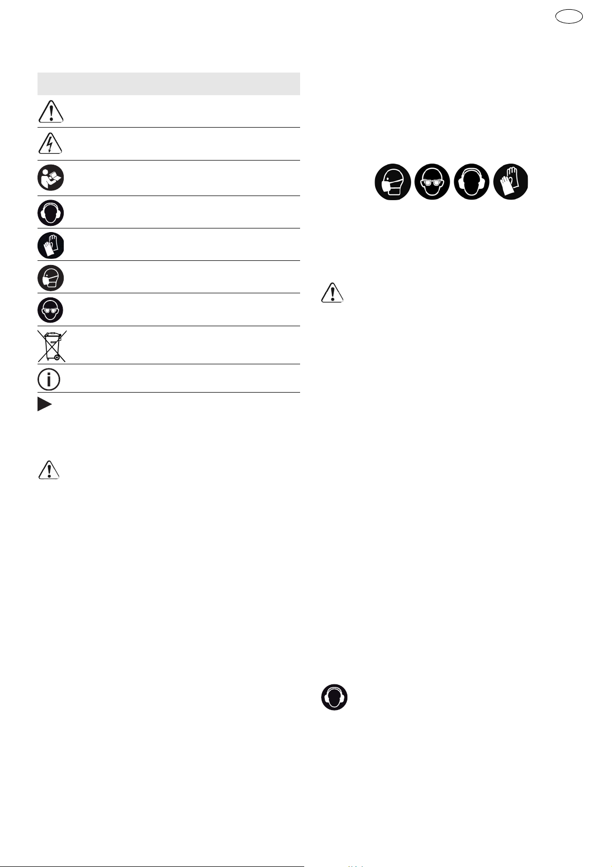
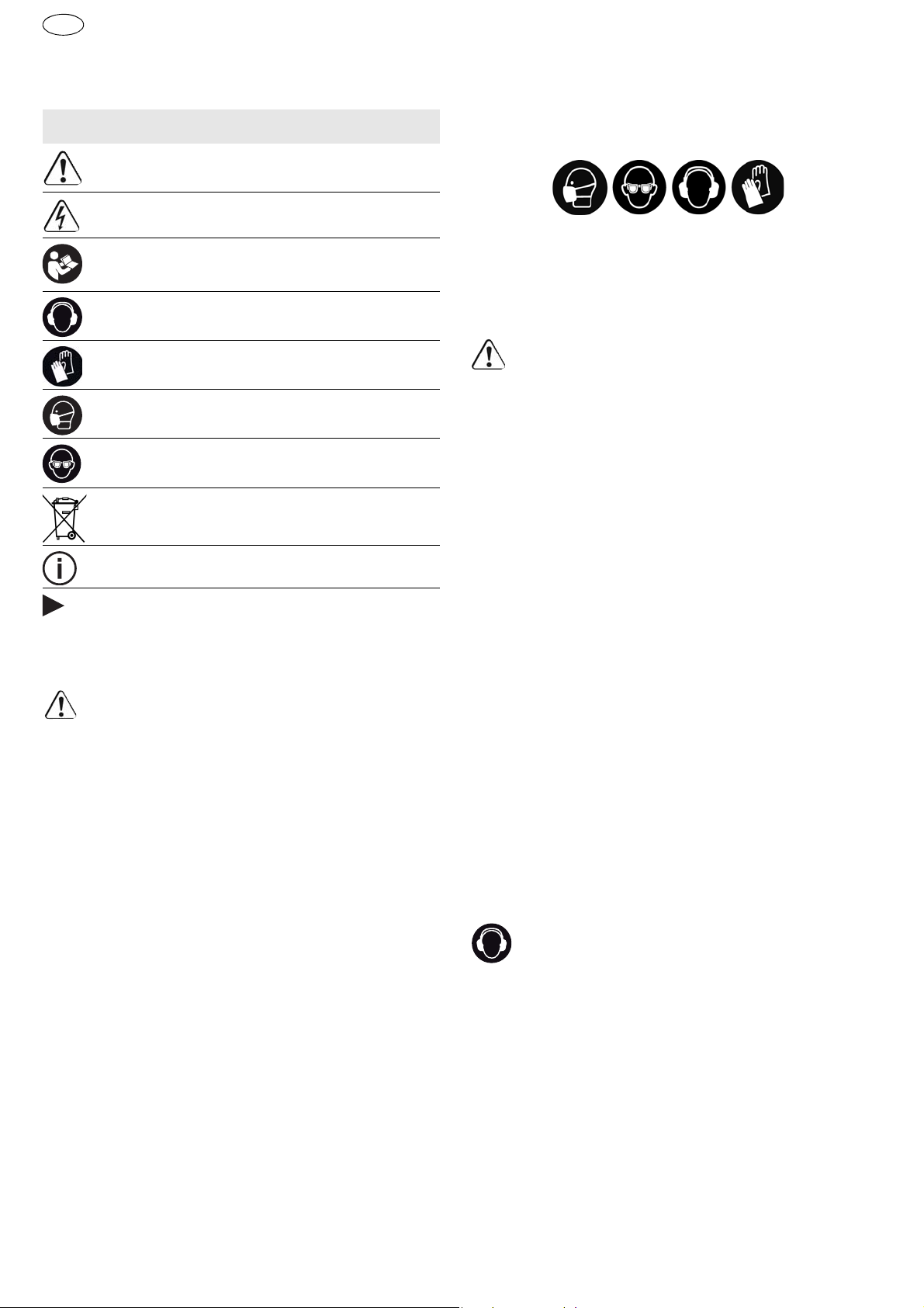
Betriebsanleitung, Sicherheitshinweise
lesen!
Gehörschutz tragen!
Schutzhandschuhe tragen!
Atemschutz tragen!
Schutzbrille tragen!
Nicht in den Hausmüll geben.
Tipp, Hinweis
Handlungsanweisung
2 Sicherheitshinweise
2.1 Allgemeine Sicherheitshinweise
Warnung!
se und Anweisungen.
Einhaltung der Sicherheitshinweise und Anweisungen können elektrischen Schlag, Brand und/oder
schwere Verletzungen verursachen.
Bewahren Sie alle Sicherheitshinweise und Anweisungen für die Zukunft auf.
Der in den Sicherheitshinweisen verwendete Begriff „Elektrowerkzeug“ bezieht sich auf netzbetriebene Elektrowerkzeuge (mit Netzleitung) und
auf akkubetriebene Elektrowerkzeuge (ohne Netzleitung).
Lesen Sie alle Sicherheitshinwei-
Versäumnisse bei der
–
Tragen Sie geeignete persönliche Schutzausrüstungen:
Gehörschutz, Schutzbrille, Staubmaske
bei stauberzeugenden Arbeiten, Schutzhandschuhe beim Bearbeiten rauer Materialien und beim
Werkzeugwechsel.
VORSICHT! Elektrowerkzeug kann blockieren und plötzlichen Rückschlag verursachen!
Sofort ausschalten!
–
Halten Sie das Elektrowerkzeug fest in der Hand.
Stellen Sie das Drehmoment beim Schrauben
korrekt ein. Seien Sie auf ein hohes Reaktionsmoment gefasst,
die eine Drehung des Elektrowerkzeugs verursachen und zu Verletzungen
führen können.
–
Verwenden Sie das Elektrowerkzeug nicht im Regen oder in feuchter Umgebung.
Feuchtigkeit im
Elektrowerkzeug kann zu Kurzschluss und Brand
führen.
– Ein-/Ausschalter nicht dauerhaft arretieren!
– Durch Verbindung von Magazinvorsatz und Tro-
ckenbauschrauber entsteht ein Gerät, für welches die Sicherheitsvorschriften und -hinweise
des Trockenbauschraubers gelten.
2.3 Emissionswerte
Die nach EN 60745 ermittelten Werte betragen typischerweise:
Schalldruckpegel LPA = 78 dB(A)
Schallleistungspegel LWA = 89 dB(A)
Unsicherheit K = 3 dB
Gehörschutz tragen!
2.2 Maschinenspezifische Sicherheitshinweise
–
Halten Sie das Gerät nur an den isolierten
Griffflächen, wenn Sie Arbeiten ausführen, bei
denen die Schraube verborgene Stromleitungen treffen kann.
Der Kontakt der Schraube mit
einer spannungsführenden Leitung kann auch
metallene Geräteteile unter Spannung setzen
und zu einem elektrischen Schlag führen.
–
Verwenden Sie geeignete Suchgeräte, um verborgene Versorgungsleitungen aufzuspüren,
Schwingungsemissionswert ah (Vektorsumme
dreier Richtungen) und Unsicherheit K ermittelt
entsprechend EN 60745:
DWC 18-2500
ah = 2,8 m/s
K = 1,5 m/s
DWC 18-4500
ah = 3,5 m/s
K = 1,5 m/s
Die angegebenen Emissionswerte (Vibration, Geräusch)
2
2
2
2
7
Page 8
DWC
D
– dienen dem Maschinenvergleich,
– eignen sich auch für eine vorläufige Einschät-
zung der Vibrations- und Geräuschbelastung
beim Einsatz,
– repräsentieren die hauptsächlichen Anwendun-
gen des Elektrowerkzeugs.
Erhöhung möglich bei anderen Anwendungen, mit
anderen Einsatzwerkzeugen oder wenn ungenügend gewartet. Leerlauf- und Stillstandszeiten der
Maschine beachten!
3 Bestimmungsgemäße Verwendung
Trockenbauschrauber geeignet für folgende
Schraubarbeiten:
DWC 18-2500
– Gipsfaserplatten auf Metall- und Holzkonstrukti-
onen mit Schnellbauschrauben mit Fräsrippen
– Spanplatten/OSB auf Holzkonstruktion mit Holz-
bau- und Spanplattenschrauben bis D 5 mm
DWC 18-4500
– Gipskartonplatten auf Metallprofilschienen
(≤ 0,88 mm) mit Schnellbauschrauben mit Feingewinde
– Gipskartonplatten auf Metallprofilschienen
(≤ 2,25 mm) mit Schnellbauschrauben mit Bohrspitze
– Gipskartonplatten auf Holzkonstruktionen mit
Schnellbauschrauben mit Grobgewinde
Bei nicht bestimmungsgemäßem Gebrauch
haftet der Benutzer; dazu zählt auch industrieller Dauerbetrieb.
4 Technische Daten
Akku-Trockenbauschrauber DWC 18-2500 DWC 18-4500
Motorspannung 18 V 18 V
Leerlaufdrehzahl* 0 - 2500 min
Drehmoment (weich/hart) 7 / 18 Nm 5 / 14 Nm
Werkzeugaufnahme 1/4 ’’ DIN 3126 / ISO 1173 1/4 ’’ DIN 3126 / ISO 1173
Max. verarbeitbare Schraubenlänge 55 mm 55 mm
Gewicht ohne Akkupack 1,2 kg
Gewicht mit Tiefenanschlag ohne Akkupack 1,3 kg
Gewicht mit Magazinvorsatz ohne Akkupack 1,6 kg
* Drehzahl-Angaben mit voll geladenem Akkupack.
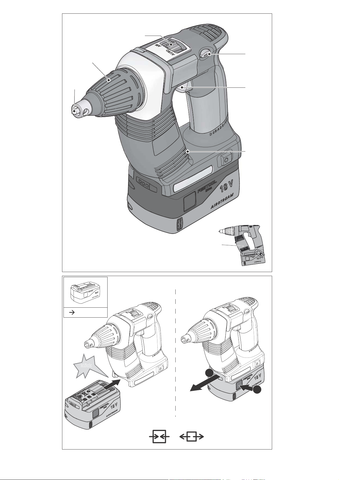
5 Geräteelemente
[1-1]
[1-2]
[1-3]
[1-4]
[1-5]
[1-6]
Bit-Depot
Ein-/Ausschalter
Schalter für Rechts-/Links-Lauf
Umschalter AUTO/MAN
Tiefenanschlag
Bit
6 Inbetriebnahme
6.1 Akkupack wechseln
Akkupack einsetzen
Akkupack abnehmen
Akkupack ist bei Lieferung sofort einsatzbereit
und kann jederzeit aufgeladen werden.
7 Einstellungen
-1
0 - 4500 min
[2 A]
[2 B]
-1
[1-7]
Abgebildetes oder beschriebenes Zubehör gehört
teilweise nicht in den Lieferumfang.
Die angegebenen Abbildungen befinden sich am
Anfang der Betriebsanleitung.
8
Isolierte Griffflächen (grau schattierter
Bereich)
VORSICHT
Verletzungsgefahr
Einstellungen nur bei ausgeschaltetem Elektrowerkzeug!
7.1 Drehrichtung ändern [1-3]
• Schalter nach links = Rechtslauf
• Schalter nach rechts = Linkslauf
Page 9

8 Werkzeugaufnahme, Vorsatzgeräte
WARNUNG
Verletzungsgefahr
Vor allen Arbeiten am Elektrowerkzeug den Akkupack vom Elektrowerkzeug abnehmen!
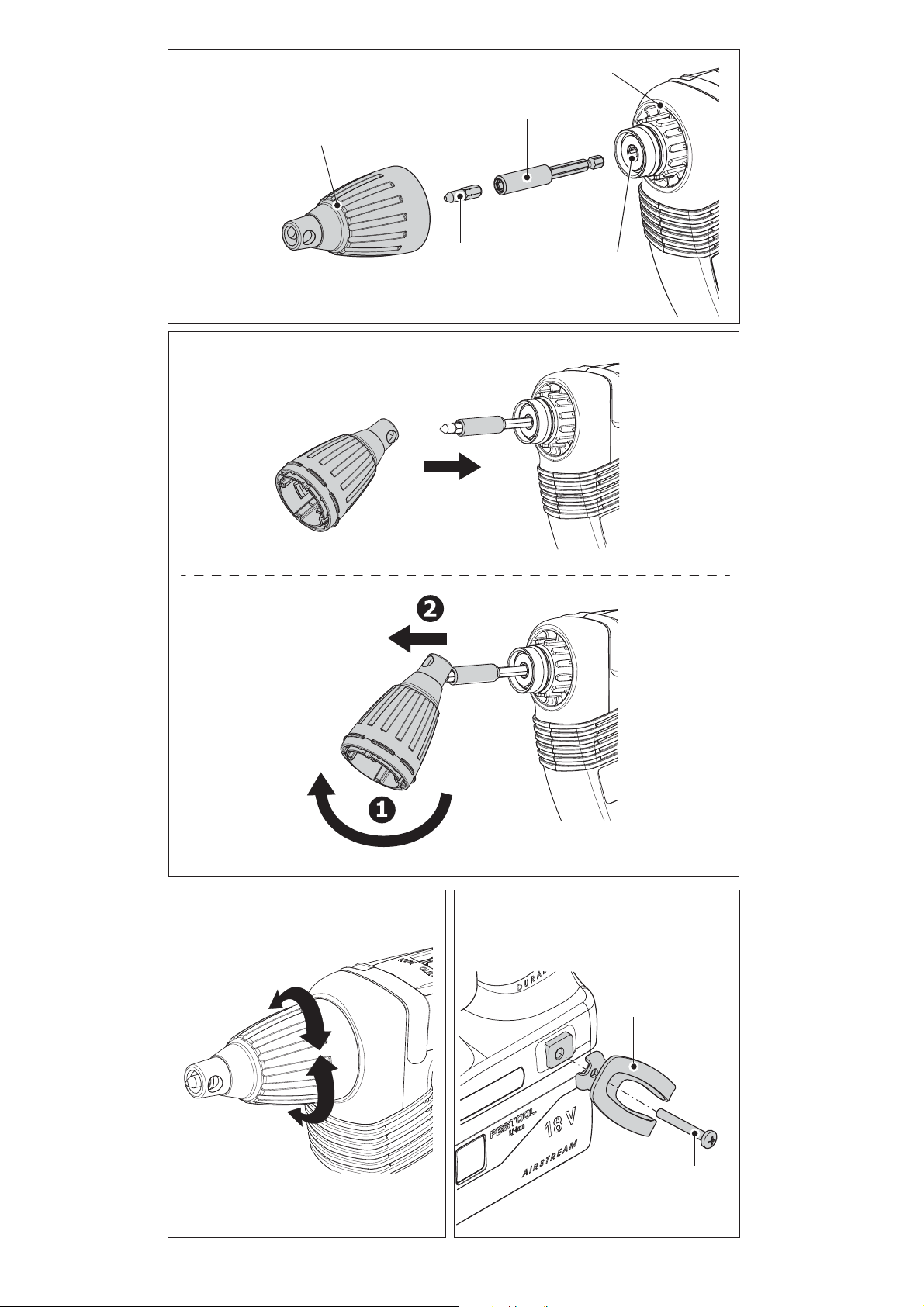
8.1 Bithalter
Der Bithalter ermöglicht das rasche Auswechseln
der Bits.
VORSICHT
Heißes und scharfes Werkzeug
Verletzungsgefahr
Keine stumpfen und defekten Einsatzwerkzeuge
verwenden!
Schutzhandschuhe tragen.
Bithalter montieren
Schalter
Den Bithalter
[4-4]
Bit
Danach den Tiefenanschlag am Getriebegehäuse anbringen wie in Kapitel 9.2 beschrieben.
Bithalter demontieren
Den Tiefenanschlag wie in Kapitel 9.2 beschrieben abnehmen.
Den Bithalter durch kräftiges Ziehen aus der
Werkzeugaufnahme entnehmen.
8.2 Bit wechseln
Zum Wechseln des Bits
fenanschlag
Hierfür den Tiefenanschlag wie in Bild
zeigt auf den Bit aufsetzen.
Durch Verkanten des Tiefenanschlags mit dem
Bit und gleichzeitigem Ziehen kann der Bit abgezogen werden.
Danach neuen Bit in den Bithalter einsetzen.
[1-4]
auf Position MAN stellen.
[4-2]
in die Werkzeugaufnahme
einstecken bis er einrastet.
[4-3]
im Halter einsetzen.
[1-6]
können Sie den Tie-
[1-5]
benutzen.
[4b]
ge-
DWC
D
a)
Mittels Rechts-/Links-Schalter
[1-3]
den
Rechtslauf des Geräts einstellen.
Umschalter
Um das Gerät einzuschalten, Schalter
[1-4]
auf Position MAN stellen.
[1-2]
betätigen und gleichzeitig mit dem Bit auf die
Schraube drücken.
Durch Druck auf den Schalter
[1-2]
kann die Dreh-
zahl stufenlos verändert werden.
b)
Mittels Rechts-/Links-Schalter
[1-3]
den
Rechtslauf des Geräts einstellen.
Umschalter
Um das Gerät einzuschalten, mit dem Bit auf die
[1-4]
auf Position AUTO stellen.
Schraube drücken.
Es ist kein Drücken des Schalters
[1-2]
notwendig!
Die Höchstdrehzahl ist automatisch eingestellt.
c)
Mittels Rechts-/Links-Schalter
[1-3]
den
Linkslauf des Geräts einstellen.
Gerät mittels Schalter
Der Umschalter MAN/AUTO
[1-2]
einschalten.
[1-4]
ist in beliebi-
ger Position.
Durch Druck auf den Schalter
[1-2]
kann die Dreh-
zahl stufenlos verändert werden.
Der Trockenbauschrauber läuft im Linkslauf allein durch Drücken des Schalters
[1-2]
ohne
zusätzlichen Druck auf den Bit.
Zum Ausschrauben von Schrauben muss der
Tiefenanschlag deshalb nicht abgenommen
werden.
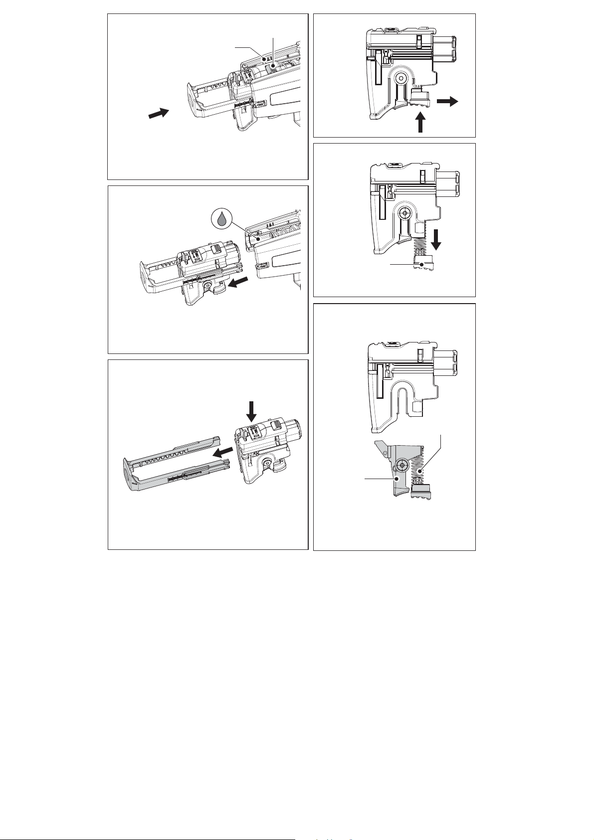
9.2 Tiefenanschlag
Durch Drehen am Tiefenanschlag
Schraubtiefe eingestellt werden, wie in Bild
[1-5]
kann die
[5]
ge-
zeigt. Die Einstellgenauigkeit beträgt ca ± 0,1 mm.
Linksdrehung Schraube wird tiefer versenkt.
Rechtsdrehung Schraube wird weniger tief ver-
senkt
Nach der Tiefeneinstellung Probeverschraubung
durchführen, danach die Tiefe ggf. korrigieren.
9 Arbeiten mit der Maschine
9.1 Ein-/Ausschalten [1-2]
Das Gerät wird nicht allein durch Drücken des
Schalters
Nach dem Einschrauben auf die gewünschte
Tiefe schaltet das Gerät automatisch ab!
Das Gerät lässt sich auf verschiedene Weise einschalten:
[1-2]
gestartet –
kein Gerätedefekt
!
Tiefenanschlag montieren
Den Tiefenanschlag
häuse
Danach mit Druck aufstecken bis der Tiefenan-
[4-5]
aufsetzen.
[4-1]
auf das Getriebege-
schlag hörbar einrastet.
Tiefenanschlag demontieren
Durch kräftiges Ziehen den Tiefenanschlag vom
Getriebegehäuse abnehmen.
9
Page 10

DWC
D
9.3 Gerüsthaken und Gürtelclip
Mit dem Gürtelclip
[6-1]
kann das Gerät vorübergehend an der Arbeitskleidung befestigt werden – er
kann links- oder rechts am Gerät mittels Schraube
[6-2]
montiert werden und ist somit für Rechts-
und Linkshänder geeignet – siehe Bild
Das Gerät ist mit einem Haken
[7-1]
[6]
.
versehen, der
zum gelegentlichen Aufhängen des Gerätes dient.
Er kann links- oder rechts am Gehäuse mit der
Schraube
[7-2]
montiert werden – siehe Bild
[7]
.
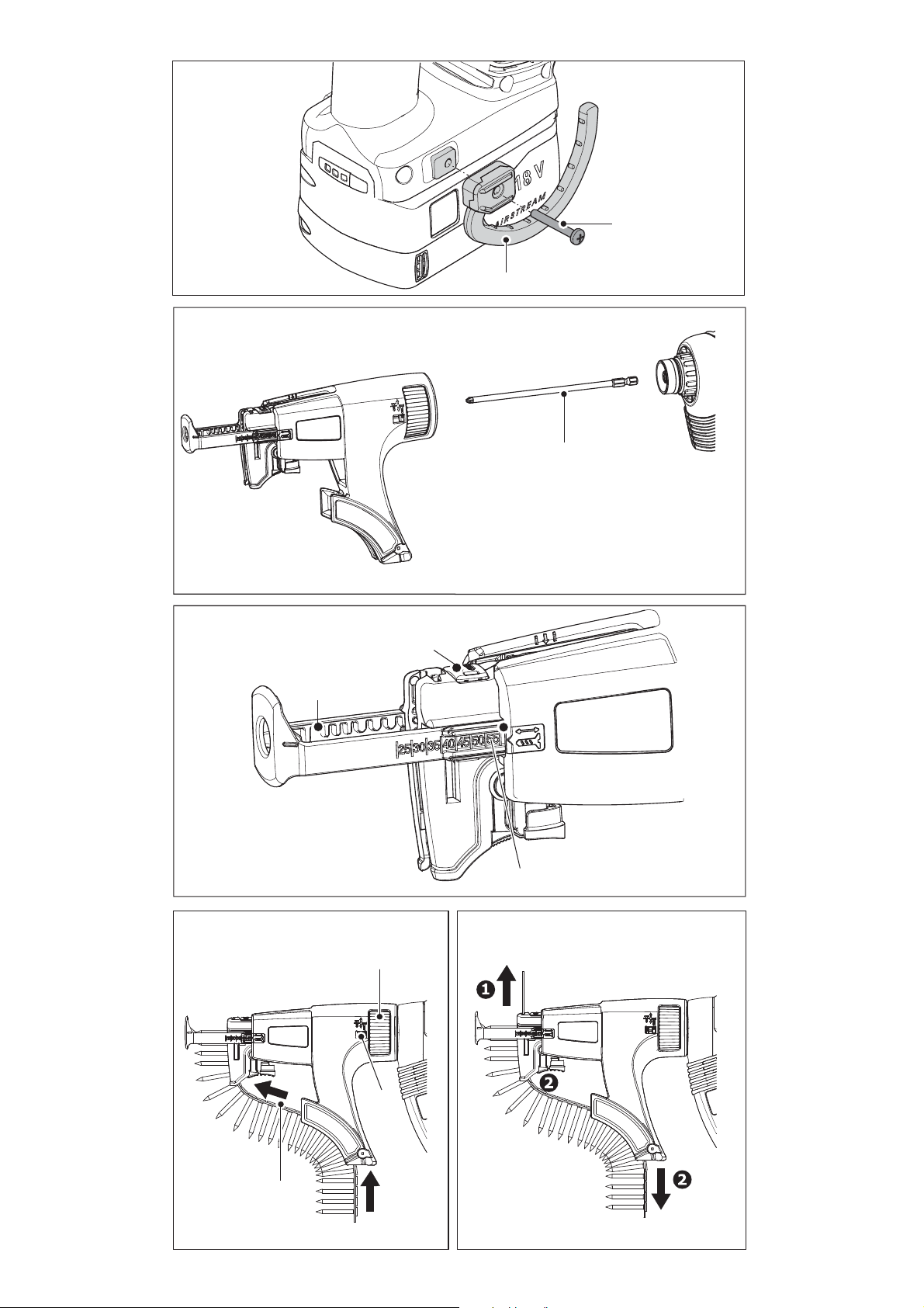
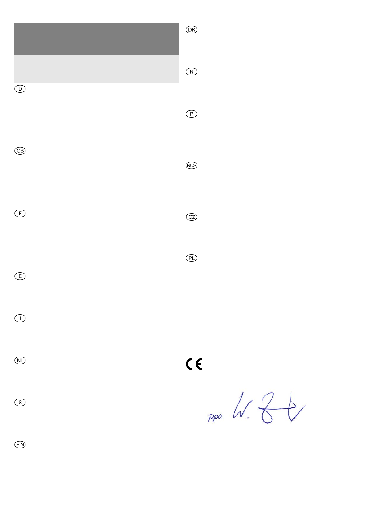
9.4 Magazinvorsatz
Mithilfe des Magazinvorsatzes kann fortlaufend,
ohne unnötige Pausen, gearbeitet werden.
Nach erfolgter Einstellung Probeverschraubung
durchführen, danach ggf. mittels Stellrad
[10-1]
die Tiefeneinstellung korrigieren. Jede Veränderung der Einstellung entspricht einer Verschiebung
des Anschlags um ± 0,1 mm.
Wir empfehlen im automatischen Modus zu
schrauben – siehe Kapitel 9.1 b).
Entnahme des Schraubengurts
Die Entnahme des Schraubengurtes erfolgt
durch einfachen Zug nach oben (Bild
[11]
)
oder durch Betätigen des Transporthebels und
gleichzeitiges Ziehen am Schraubengurt nach
unten (Bild
[11]
).
Magazinvorsatz montieren
Wie in Kapitel 8 beschrieben, Tiefenanschlag
[4-1]
auf Bithalter
Umschalter
Den langen Bit
[4-4]
einstecken, bis er einrastet.
Danach den Magazinvorsatz am Getriebege-
[1-4]
[4-2]
mit Bit abnehmen.
in Position MAN stellen.
[8-1]
in die Werkzeugaufnahme
häuse anbringen. Der Magazinvorsatz muss
hörbar einrasten.
Der Magazinvorsatz kann in 30°-Abständen positioniert werden.
Magazinvorsatz demontieren
Durch kräftiges Ziehen den Magazinvorsatz vom
Getriebegehäuse abnehmen.
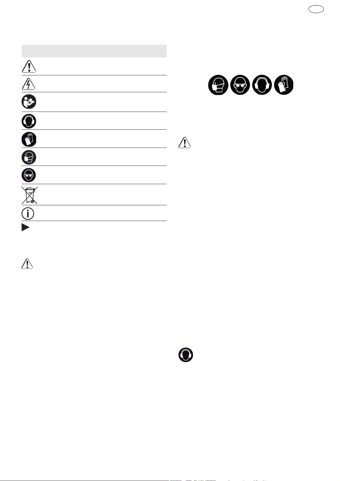
Einstellung der Schraubenlänge
Durch Druck auf die Taste
fenanschlag
[9-2]
ein- oder ausgerückt wer-
[9-1]
kann der Tie-
den, wodurch er auf die gewünschte Schraubenlänge eingestellt werden kann.
Die eingestellte Schraubenlänge ist an den Seiten
des Tiefenanschlags
[9-3]
ablesbar.
Einlegen der Schraubengurte
Den Schraubengurt
[10-3]
zuerst durch die untere Magazinführung ziehen und danach in die
Schlittenführung einfädeln bis die Schraube in
ihrer Arbeitsposition einrastet.
Überzeugen Sie sich durch sanften Zug am
Schraubengurt, dass er korrekt und sicher sitzt.
Kontrollieren Sie, ob die erste Schraube in der
Schraubachse liegt – siehe Bild
Mittels Stellrad
[10-1]
die erforderliche Ein-
[10]
.
schraubtiefe einstellen.
Durch Rechtsdrehen werden die Schrauben tiefer versenkt, durch Linksdrehen werden die
Schrauben weniger tief versenkt. An der Vorwahlanzeige
[10-2]
kann die aktuelle Einstel-
lung abgelesen werden
10 Arbeitshinweise
– Der Magazinvorsatz darf nicht im Bereich des
Tiefenanschlags gehalten werden!
– Jeder Schraubvorgang muss bis zu Ende ausge-
führt werden. Die Unterbrechung des Schraubvorgangs oder der Druckausübung beim
Schrauben kann Funktionsstörungen am Gerät
verursachen.
– Die Schraubengurte dürfen nur bei Stillstand des
Geräts ausgewechselt werden.
– Den Magazinvorsatz keinesfalls auf andere, als
in dieser Bedienungsanleitung beschriebenen
Weise verwenden.
– Ausschließlich Original-Schraubbits verwenden.
– Ausschließlich Original gegurtete Schrauben
verwenden.
– Die Schraubengurte jeweils immer in der Origi-
nalpackung aufbewahren.
– Immer im rechten Winkel zu der zu befestigen-
den Platte arbeiten.
10.1 Wartung des Magazinvorsatzes
Der Magazinvorsatz ist im Prinzip wartungsfrei.
Nach längerer Verwendung empfiehlt es sich, ihn
mit Druckluft zu reinigen.
Der Magazinvorsatz darf im Bereich der Schlittenführung – siehe Bild
Zur Reinigung kann der Magazinvorsatz, wie in den
folgenden Punkten beschrieben, zerlegt werden.
Vor der Reinigung den Schraubengurt auf die im
Kapitel 9.4 Absatz <Entnahme des Schraubengurts> beschriebene Weise aus dem Magazin entnehmen.
Den Magazinvorsatz vom Trockenbauschrauber
abnehmen.
[12b]
– geschmiert werden.
10
Page 11
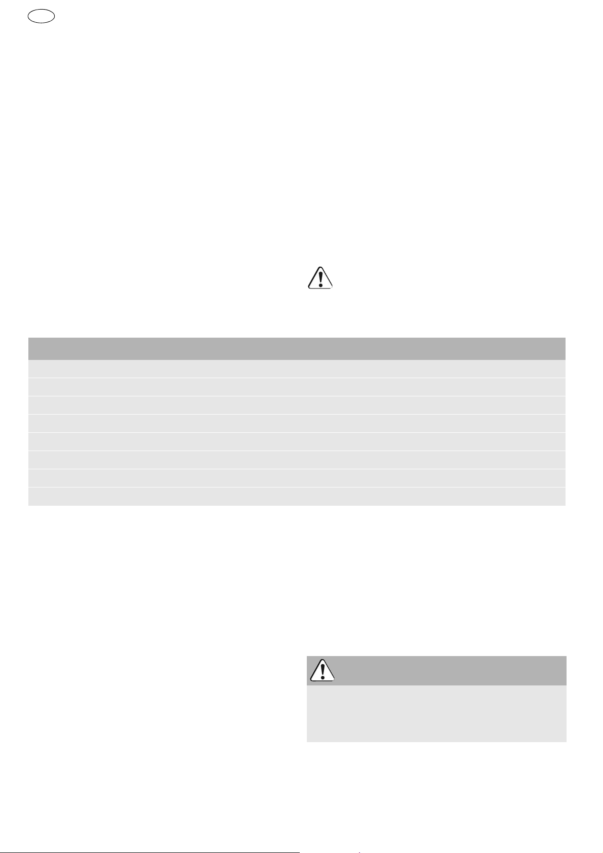
Schlittendemontage
Den Tiefenanschlag
[9-2]
so weit in das Gehäu-
se eindrücken, bis sich die Arretierungstaste
[12-1]
demontage
Arretierungstaste
auf Höhe der Markierung zur Schlitten-
[12-2]
befindet – siehe Bild
[12-1]
drücken und gleich-
[12a]
.
zeitig den Schlitten aus dem Magazin ziehen –
siehe Bild
Taste
anschlag lösen – siehe Bild
[12b]
.
[9-1]
drücken und gleichzeitig den Tiefen-
[12c]
.
Demontage des Transporthebels
Taste
richtung schieben – siehe Bild
Die frei gewordene Taste
sammen mit dem Transporthebel
mit der Feder
men (Bild
Die einzelnen Teile reinigen, defekte oder abge-
[13-1]
[13c]
drücken und gleichzeitig in Pfeil-
[13a]
.
[13-3]
[13-1]
aus dem Schlitten entneh-
(Bild
[13b]
[13-2]
) zu-
und
).
nutzte Teile auswechseln und danach in umgekehrter Reihenfolge montieren.
Beim Wiedereinbau des Transporthebels in
den Schlitten auf den korrekten Sitz der Feder
[13-3]
im Transporthebel achten. Eine
fehlerhafte Montage kann den Schraubengurttransport stören.
10.2 Akustische Warnsignale
Akustische Warnsignale ertönen bei folgenden Betriebszuständen und die Maschine schaltet ab:
Akku leer oder Maschine überlastet.
– Wechseln Sie den Akku.
– Belasten Sie die Maschine weni-
ger.
Maschine ist überhitzt.
– Nach Abkühlung können Sie die
Maschine wieder in Betrieb nehmen.
LiIon-Akkupack ist überhitzt oder
defekt.
– Prüfen Sie die Funktionsfähigkeit
bei abgekühltem Akkupack mit
dem Ladegerät.
DWC
D
11 Wartung und Pflege
WARNUNG
Verletzungsgefahr, Stromschlag
Vor allen Wartungs- und Pflegearbeiten stets
den Akkupack von dem Elektrowerkzeug abnehmen!
Alle Wartungs- und Reparaturarbeiten, die ein
Öffnen des Motorgehäuses erfordern, dürfen
nur von einer autorisierten Kundendienstwerkstatt durchgeführt werden.
Kundendienst und Reparatur
nur
durch Hersteller oder durch Servicewerkstätten: Nächstgelegene Adresse
unter: www.festool.com/service
EKAT
4
Nur original Festool Ersatzteile verwenden! Bestell-Nr. unter:
5
3
2
1
www.festool.com/service
Folgende Hinweise beachten:
– Die Lüftungsöffnungen am Elektrowerkzeug frei
und sauber halten, damit die Kühlung gewährleistet ist.
– Die Anschlusskontakte am Elektrowerkzeug, La-
degerät und Akkupack sauber halten.
Für Wartung, Pflege, Entsorgung und Transport des Akkupacks, dem Akkupack beilie-
gende Hinweise beachten!
12 Umwelt
Gerät nicht in den Hausmüll werfen!
Geräte, Zubehör und Verpackungen einer umweltgerechten Wiederverwertung zuführen. Geltende nationale Vorschriften beachten.
Nur EU:
tro- und Elektronik-Altgeräte und Umsetzung in
nationales Recht müssen verbrauchte Elektrowerkzeuge getrennt gesammelt und einer umweltgerechten Wiederverwertung zugeführt werden.
Informationen zur REACh:
Gemäß Europäischer Richtlinie über Elek-
www.festool.com/reach
11
Page 12

DWC
GB
Original operating manual
1Symbols
Symbol Significance
Warning of general danger
Risk of electric shock
Read operating instructions and safety
notices!
Wear ear protection.
Wear protective gloves.
Wear a dust mask.
Wear protective goggles.
Do not dispose of as domestic waste.
Tip or advice
Handling instruction
–
Wear suitable protection:
such as ear protection, safety goggles, a dust mask for work which
generates dust, and protective gloves when
working with raw materials and when changing
tools.
CAUTION! Power tool can block and cause
sudden kickback!
–
Hold the power tool firmly in your hand. Adjust
Switch off immediately!
the torque correctly for screwing. Be prepared
for a high reaction torque,
which may cause the
power tool to turn and possibly lead to injury.
–
Do not use the power tool in the rain or in damp
surroundings.
Moisture in the power tool may
cause a short circuit and burning.
– Do not lock the on/off switch permanently!
– Connecting the magazine attachment and dry-
wall screwdriver results in a device, which is subject to the safety regulations and instruction for
the drywall screwdriver.
2.3 Emission levels
Levels determined in accordance with EN 60745 are
typically:
2 Safety instructions
2.1 General safety instructions
WARNING!
structions, illustrations and specifications
provided with this power tool.
instructions listed below may result in electric
shock, fire and/or serious injury.
Save all warnings and instructions for future reference.
The term "power tool" in the warnings refers to
your mains-operated (corded) power tool or battery-operated (cordless) power tool.
2.2 Machine-related safety instructions
–
Hold power tool by insulated gripping surface,
when performing an operation where the fastener may contact hidden wiring.
tacting a "live" wire may make exposed metal
parts of the power tool "live" and could give the
operator an electric shock.
–
Use suitable detectors to determine if utility
lines are hidden in the work area or call the local utility company for assistance.
electric lines can lead to fire and electric shock.
Damaging a gas line can lead to explosion. Penetrating a water line causes property damage or
may cause an electric shock.
Read all safety warnings, in-
Failure to follow all
Fasteners con-
Contact with
Sound pressure level LPA = 78 dB(A)
Sound power level LWA = 89 dB(A)
Uncertainty K = 3 dB
Wear ear protection.
Vibration emission value ah (vector sum for three
directions) and uncertainty K measured in accordance with EN 60745:
DWC 18-2500
DWC 18-4500
ah = 2,8 m/s
K = 1,5 m/s
ah = 3,5 m/s
K = 1,5 m/s
2
2
2
2
The specified emission values (vibration, noise)
– are used to compare machines.
– They are also used for making preliminary esti-
mates regarding vibration and noise loads during
operation.
– They represent the primary applications of the
power tool.
Increase possible for other applications, with other
insertion tools or if not maintained adequately. Take
note of idling and downtimes of machine!
12
Page 13
3 Intended use
The drywall screwdriver is designed for the following works:
DWC 18-2500
– Gypsum fibreboards on metal and wooden con-
structions - Drywall screws with milling ribs
– Chip boards/OSB on wooden constructions bis D
5 mm - Wood construction and chip board screws
up to dia. 5 mm
DWC
DWC 18-4500
– Gypsum plaster boards on metal profile rails
(≤ 0.88 mm) - Drywall screws with fine thread
– Gypsum plaster boards on metal profile rails
(≤ 2.25 mm) - Drywall screws, self-drilling
– Gypsum plaster boards on wooden constructions
- Drywall screws with coarse thread
The user is liable for improper or non-intended use; this also includes continuous industrial operation.
GB
4Technical data
Cordless drywall screwdriver DWC18-2500 DWC18-4500
Motor voltage 18 V 18 V
Idle speed* 0 - 2500 min
Torque (hard / soft) 7 / 18 Nm 5 / 14 Nm
Chuck 1/4 ’’ DIN 3126 / ISO 1173 1/4 ’’ DIN 3126 / ISO 1173
-1
0 - 4500 min
-1
Maximum workable screw length 55 mm 55 mm
Weight (without battery pack) 1,2 kg
Weight with depth stop (without battery pack) 1,3 kg
Weight with magazine attachment (without
battery pack)
* Speed specifications with fully charged battery pack.
5 Machine features
[1-1]
[1-2]
[1-3]
[1-4]
[1-5]
[1-6]
[1-7]
Accessories shown or described are sometimes not
included in the scope of delivery.
The specified illustrations appear at the beginning
of the Operating Instructions.
Bit store
On/Off switch
Right/left switch
AUTO/MAN switch
Depth stop
Bit
Insulated gripping surfaces (grey shaded
area)
6 Commissioning
6.1 Changing the battery pack
Inserting the battery pack [2 A]
Removing the battery pack[2 B]
Battery pack is ready for use immediately upon
delivery and can be charged at any time.
7 Settings
Risk of injury
Always switch off the power tool before adjusting
settings!
7.1 Changing direction of rotation [1-3]
• Switch to the left = clockwise rotation
• Switch to the right = counterclockwise rotation
8 Tool holder, attachments
Risk of injury
Always disconnect the battery pack before performing any type of work on the machine!
8.1 Bit holder
The bit holder is used for fast replacement of bits.
1,6 kg
CAUTION
WARNING
13
Page 14

DWC
GB
CAUTION
Hot and sharp tools
Risk of injury
Do not use insert tools that are blunt or defective.
Wear protective gloves.
b)
Set the forward / reverse switch
[1-3]
into ma-
chine clockwise operation.
Set the switch
Press the bit on the screw and the power tool
[1-4]
into AUTO position.
will switch on.
Switch
[1-2]
does not need to be pressed. Maxi-
mum speed is set automatically.
Bit holder assembly
Set the switch
Set the bit holder
onal spindle opening
Attach bit into the holder
Then attach the depth stopper on the gear box
[1-4]
into MAN position.
[4-2]
completely to the hexag-
[4-4]
.
[4-3]
.
as specified in chapter 9.2.
Bit holder disassembly
Remove the depth stopper as specified in chapter 9.2.
Use power to pull out the holder from the spindle opening.
8.2 Bit replacement
You can use the depth stopper
placement
Attach the depth stopper on the bit (see figure
[4b]
By means of jamming the depth stopper with
.
[1-5]
.
[1-6]
for the bit re-
the bit and concurrent pulling, it is possible to
pull out the bit.
Then attach a new bit in the holder.
9 Working with the machine
9.1 On/Off switch [1-2]
Pressing only the switch
machine –
Upon screwing to the required depth, the power
it is not a machine fault
tool switches off!
The machine can be switched on by means of several methods:
a)
Set the forward / reverse switch
chine clockwise operation.
Set the switch
In order to switch on the power tool, apply the
switch
[1-2]
[1-4]
and concurrently press the bit on
the screw.
Use the switch
[1-2]
speed.
[1-2]
does not start the
!
[1-3]
into ma-
into MAN position.
to gradually regulate the
b)
Set the forward / reverse switch
[1-3]
into ma-
chine anti-clockwise operation.
In order to start the power tool, press the switch
[1-2]
.
The switch MAN/AUTO
Use the switch
[1-2]
[1-4]
is in any position.
to gradually regulate the
speed.
If the forward / reverse switch is set to anticlockwise operation, the screwdriver can be
started only by pressing the switch
[1-2]
without
additional pressure on the bit.
It is not necessary to remove the depth stopper
in order to unscrew screws.
9.2 Depth stop
Turning the depth stopper
depth – see figure
[5]
[1-5]
sets the screwing
. The setting accuracy is ap-
prox ± 0,1 mm.
Anti-clockwise
screws are inserted deeper
rotation
Clockwise rotation screws are inserted to lower
depth
Upon setting the depth, set some screws to test and
adjust the depth.
Depth stop assembly
Fit the depth stop
Press until it engages in the groove.
[4-1]
on the gear box
[4-5]
.
Depth stop disassembly
Remove the depth stop from the gear box by
pulling it.
9.3 Scaffolding holder and belt clip
Use the belt clip
[6-1]
to temporarily attach the
screwdriver on the working clothing – it can be attached by means of a screw
[6-2]
to the left or right
of the power tool, and it is suitable for right and left
handed people – see figure
[6]
.
The screwdriver is equipped with a scaffolding
holder
[7-1]
which is used for occasional machine
suspension. It can be attached to the left or right of
the power tool, by means of a screw
ure
[7]
.
[7-2]
– see fig-
14
Page 15

9.4 Magazine attachment
The magazine attachment enables to work continuously, without unnecessary delays.
Fitting the magazine attachment
At first remove the depth stopper
bit holder
Set the switch
Push the long bit
onal spindle opening
Then fit the magazine attachment on the gear
[4-2]
as specified in chapter 8.
[1-4]
into MAN position.
[8-1]
completely to the hexag-
[4-4]
.
[4-1]
and bit,
box. Push the attachment until it engages in the
groove of the gear box.
The attachment can be mounted at 30° steps.
Removing the magazine attachment
Use power to carefully pull the magazine attachment from the gear box.
Setting the screw length
Press button
depth stop
[9-1]
to remove and insert the
[9-2]
and set the required screw
length.
Read the set screw length on the depth stop sides
[9-3]
.
Inserting collated screw strips
Pull the collated screws
[10-3]
through the bottom guiding of the attachment, then push the
strip through the second guiding until it engages in the working position.
Pull the belt slightly to make sure that it is safely fitted.
Make sure that the first screw is in the screwing
axes – see figure
Use the wheel
[10]
[10-1]
.
to set the required screw-
ing depth.
Turn to the right for inserting the screws deeper,
and to the left to screw to lower depth. The actual setting position is visible on the presetting
indicator
[10-2]
.
Upon setting, set some screws for testing and use
the wheel
[10-1]
to adjust the depth, if required.
Each setting change complies with the stop shift o
± 0.1 mm.
We recommend to screw in automatic mode –
see point 9.1 b).
Removing the collated screws
Pull upwards to remove the belt (figure
[11]
)
or press the transport lever and concurrently
pull the belt downwards (figure
[11]
).
DWC
GB
10 Working instructions
– The magazine attachment must not be held in the
depth stop area as there are moving parts!
– Each screw adjustment must be completed. In-
terrupted fastening or releasing of the pressure
during adjustment can result in unsatisfactory
machine function.
– The collated screws and the magazine attach-
ment can only be replaced when the power tool is
turned off.
– Never use the magazine attachment in any other
way than specified in this instruction manual.
– Use only original screwing bits.
– Use only original collated screws.
– Always store the collated screws in original
packaging.
– Always work in right angle against the attached
board.
10.1 Maintenance of the magazine attach-
ment
The attachment generally does not require any
maintenance. After long period use, we recommend to clean with pressurized air.
The magazine attachment may be lubricated in the
area of the carriage guide (see picture
Prior to cleaning, dismantle the attachment, as
specified above.
Prior to cleaning, remove the collated screws from
the attachment, as specified in the chapter 9.4 point
<Removing the collated screws>.
Pull the magazine attachment from the drywall
screwdriver.
Disassembly of the slides
Push the depth stopper
until the arresting button
[9-2]
[12-1]
the sign for dismantling the slides
figure
Press the arresting button
[12a]
.
[12-1]
rently remove the slides from the holder – see
figure
Press the button
[12b]
.
[9-1]
and concurrently release
the depth stopper – see figure
Transport lever disassembly
Press the button
out – see figure
Remove the released button
[13b]
) with the transport lever
spring
Clean individual parts, replace defective or worn
[13-3]
[13-1]
[13a]
and concurrently pull it
.
from the slides (figure
parts, and assemble in the opposite sequence.
[12b]
).
into the housing
is at the level of
[12-2]
– see
and concur-
[12c]
.
[13-1]
[13-2]
(figure
and the
[13c]
).
15
Page 16
DWC
GB
During reassembly of the transport lever into
the slides, pay due care to correct fitting of
the spring
[13-3]
in the transport lever. Incorrect assembly may result in dysfunction
of the belt transport.
Customer service and repair
only
through manufacturer or service
workshops: Please find the nearest
address at: www.festool.com/service
10.2 Acoustic warning signals
Acoustic warning signal sounds and the machine
switches off to indicate the following operating
states:
Battery low or machine overloaded.
– Change the battery.
– Reduce machine workload.
Machine is overheating.
– You must allow the machine to
cool down before further usage.
Battery pack faulty or overheated.
– Once the battery pack has cooled
down, perform a function check
using the charger.
11 Service and maintenance
WARNING
Risk of injury, electric shock
Always disconnect the battery pack from the
machine before any cleaning or maintenance!
All maintenance and repair work which requires
the motor housing to be opened, must only be
carried out by an authorised service workshop.
EKAT
4
Only use original Festool spare parts!
Order No. at: www.festool.com/service
5
3
2
1
Note the following information:
– Keep the ventilation slits on the machine free and
clean to ensure adequate cooling.
– Keep the contacts on the machine, charger and
battery pack clean.
For service, maintenance, disposal and
transport of the battery pack, note enclosed
instructions of the battery pack!
12 Environment
Do not dispose of the device in household waste!
ries and packaging. Observe applicable national regulations.
EU only:
In accordance with European Directive on
waste electrical and electronic equipment and implementation in national law, used electric power
tools must be collected separately and handed in
for environmentally friendly recycling.
Information on REACh:
Recycle devices, accesso-
www.festool.com/reach
16
Page 17
Notice d'utilisation d'origine
1Symboles
Symbole Signification
Avertissement de danger
Avertissement contre le risque d'électrocution
Notice d'utilisation, lire les consignes de
sécurité !
DWC
–
Utilisez des appareils de détection appropriés
pour repérer des câbles d'alimentation dissimulés ou consultez l'entreprise de distribution
locale.
Le contact de l'outil monté avec un câble
sous tension peut provoquer un feu ou un choc
électrique. Une conduite de gaz endommagée
peut conduire à une explosion.La pénétration
dans une conduite d'eau provoque des dégâts
matériels.
F
Porter une protection auditive !
Porter des gants de protection !
Porter une protection respiratoire !
Porter des lunettes de protection !
Ne pas jeter l'appareil avec les ordures
ménagères.
Astuce, information
Consignes opératoires
2 Consignes de sécurité
2.1 Consignes générales de sécurité
Avertissement !
consignes de sécurité et instructions.
erreurs résultant du non-respect des consignes
d'avertissement et des instructions peuvent occasionner un choc électrique, des brûlures et/ou des
blessures graves.
Conservez toutes les consignes de sécurité et instructions pour une référence future.
Le terme "outil électrique" utilisé dans les
consigne de sécurité se rapporte aux outils électriques fonctionnant sur secteur (avec cordon d'alimentation) et aux outils électriques fonctionnant
sur batteries (sans cordon d'alimentation).
2.2 Consignes de sécurité spécifiques à la
machine
–
Tenez l'appareil uniquement au niveau des surfaces isolées de la poignée lorsque vous effectuez des travaux au cours desquels la vis
peuvent toucher des conduites électriques cachées.
Le contact de la vis avec un câble sous
tension peut également mettre les composants
métalliques de l'outil sous tension et provoquer
un choc électrique.
Veuillez lire toutes les
Des
–
Portez des protections adéquates:
protection
auditive, lunettes de sécurité, masque pour les
travaux générant de la poussière, gants de protection pour les travaux avec des matériaux rugueux et pour le changement d'outils.
ATTENTION ! L'outil électroportatif peut se
bloquer et provoquer un rebond brusque !
Arrêter immédiatement !
–
Tenir l'outil électroportatif bien en main. Régler
correctement le couple pour le vissage. S'attendre à un couple élevé de réaction
qui pourrait
causer une rotation de l'outil électroportatif et
entraîner des blessures.
–
Ne pas utiliser l'outil électroportatif sous la
pluie ou dans une atmosphère humide.
L'humidité dans l'outil électroportatif peut causer un
court-circuit et provoquer un incendie.
– Ne pas bloquer l'interrupteur marche/arrêt de
façon durable !
– L’assemblage du réservoir avec la visseuse sans
fil crée un appareil auquel s’appliquent les
consignes de sécurité pour la visseuse sans fil.
2.3 Valeurs d'émission
Les valeurs mesurées selon la norme NE 60745
sont habituellement :
Niveau de pression acous-
LPA = 78 dB(A)
tique
Niveau de puissance acous-
= 89 dB(A)
L
WA
tique
Incertitude K = 3 dB
Portez une protection auditive !
Valeur d'émission vibratoire ah (somme vectorielle
tridirectionnelle) et incertitude K déterminées
conformément à la norme EN 60745 :
DWC 18-2500
ah = 2,8 m/s
K = 1,5 m/s
DWC 18-4500
ah = 3,5 m/s
2
2
2
17
Page 18
DWC
F
K = 1,5 m/s
Les valeurs d'émission indiquées (vibration, bruit)
– sont destinées à des fins de comparaisons entre
les outils.
– Elles permettent également une estimation pro-
visoire de la charge de vibrations et de la nuisance sonore lors de l'utilisation
– et représentent les principales applications de
l'outil électrique.
Cependant, si la ponceuse est utilisée pour
d'autres applications, avec d'autres outils de travail
ou est insuffisamment entretenue, la charge de
vibrations et la nuisance sonore peuvent être nettement supérieures. Tenir compte des temps de ralenti et d'immobilisation de l'outil !
3 Utilisation en conformité avec les
instructions
La visseuse pour placoplâtre est appropriée pour
les travaux suivants :
2
DWC 18-2500
– Plaques de placoplâtre sur ossatures métal-
liques et bois - Vis de fixation rapide avec nervures de fraisage
– Panneaux agglomérés/ OSB sur ossatures bois -
Vis à bois et vis pour panneaux agglomérés
jusqu’à Ø 5 mm
DWC 18-4500
– Plaques de placoplâtre sur ossatures métal-
liques (rails) (≤ 0,88 mm) - Vis de fixation rapide
à filetage à pas fin
– Plaques de placoplâtre sur ossatures métal-
liques (rails) (≤ 2,25 mm) - Vis de fixation rapide
à pointe de perçage
– Plaques de placoplâtre sur ossatures bois - Vis
de fixation rapide à pas grossier
L'utilisateur est responsable des dommages
provoqués par une utilisation non conforme,
utilisation en milieu industriel comprise.
4 Caractéristiques techniques
Visseuse sans fil pour placoplâtre DWC18-2500 DWC18-4500
Tension du moteur 18 V 18 V
Vitesse à vide* 0 - 2500 min
Couple du vissage (mou / dur) 7 / 18 Nm 5 / 14 Nm
Serrage de l’instrument dans la broche 1/4 ’’ DIN 3126 / ISO 1173 1/4 ’’ DIN 3126 / ISO 1173
Profondeur de vissage maximale 55 mm 55 mm
Poids (sans bloc batterie) 1,2 kg
Poids avec butée de profondeur (sans batterie) 1,3 kg
Poids avec réservoir (sans batterie) 1,6 kg
* Indications de vitesse de rotation avec batterie entièrement chargée.
5 Composants de l’appareil
[1-1]
[1-2]
[1-3]
[1-4]
[1-5]
[1-6]
Support d’embouts
Interrupteur de marche/arrêt
Commutateur pour rotation à droite /
rotation à gauche
Commutateur AUTO/MAN
Butée de profondeur
Embout
6 Mise en service
6.1 Remplacement de la batterie
Insérer la batterie [2 A]
Retirer la batterie [2 B]
La batterie peut être utilisée immédiatement
après livraison et peut être chargée à tout moment.
7 Réglages
-1
0 - 4500 min
-1
[1-7]
Les accessoires illustrés ou décrits ne sont partiellement pas contenus dans le volume de livraison.
Les illustrations indiquées se trouvent en début de
notice d'utilisation.
18
Poignée isolée (zone grisée)
ATTENTION
Risque de blessures
Réglages à effectuer uniquement quand l'outil
électroportatif est à l'arrêt !
Page 19
7.1 Modification du sens de rotation [1-3]
• Commutateur vers la gauche = rotation à droite
• Commutateur vers la droite = rotation à gauche
8 Porte-outil, embouts
AVERTISSEMENT
Risque de blessures
Retirer systématiquement la batterie de l'outil
avant tous les travaux sur l'outil !
8.1 Mandrin
Le mandrin permet un remplacement rapide des
embouts.
DWC
Après le vissage à la profondeur exigée la ma-
F
chine s’arrête toute seule!
Il y a plusieurs façons de mettre la machine en
marche:
a)
A l’aide du commutateur
[1-3]
ajustez la rota-
tion de la machine à droite.
Ajustez le commutateur
[1-4]
dans la position
MAN.
Pour mettre la machine en marche pressez l’interrupteur
[1-2]
et en même temps appuyez sur
la vis avec l’embout.
Utilisez le commutateur
[1-2]
pour régler la vi-
tessede rotation.
ATTENTION
Outil chaud et tranchant
Risque de blessures
Ne pas utiliser d'outil émoussé ou défectueux !
Porter des gants de protection.
Montage du mandrin
Ajustez le commutateur
[1-4]
dans la position
MAN.
Introduisez le mandrin
[4-2]
jusqu’en butée
dans le logement à six pans de la broche
Fixez l’embout dans le mandrin
Ensuite montez la butée de profondeur sur le
[4-3]
.
coffret de transmission tel que décrit à l’article
9.2 .
Démontage du mandrin
Enlevez la butée de profondeur selon la déscription dans 9.2
Retirez le mandrin de la broche avec force.
8.2 Remplacement de l’embout
Pour remplacer l’embout
serla butée de profondeur
Montez celle-ci sur l’embout (voir fig.
En mettant la butée de profondeur et l’embout
[1-6]
vous pouvez utili-
[1-5]
.
[4b]
de travers et en tirant en même temps, vous
pouvez retirer l’embout.
Ensuite montez un nouvel embout dans le mandrin.
9 Travail avec la machine
9.1 Marche/arrêt [1-2]
La machine ne se met pas en marche suite à
l’appui sur le commutateur seulement
ceci n’est pas un défaut de la machine
!
[4-4]
.
[1-2]
–
b)
A l’aide du commutateur
[1-3]
ajustez la rota-
tion de la machine à droite.
Ajustez le commutateur
[1-4]
dans la position
AUTO.
Pour mettre la machine en marche, poussez
l’embout sur la vis.
Il n’est pas nécessaire d’allumer le commutateur
[1-2]
! La vitesse maximale de rotation est réglée
automatiquement.
c)
.
A l’aide du commutateur
[1-3]
ajustez la rota-
tion de la machine à gauche.
Pour mettre la machine en marche appuyez sur
l’interrupteur
Le commutateur MAN/AUTO
[1-2]
.
[1-4]
dans une des positions.
La vitesse de rotation est réglable à l’aide de l’interrupteur
[1-2]
.
Si la rotation à gauche est réglée à l’aide de l’interrupteur
[1-2],
la visseuse peut être mise en
marche par un simple appui sur l’interrupteur –
sans pression supplémentaire sur l’embout.
La butée de profondeur ne doit donc pas être
démontée pour dévisser les vis.
9.2 Butée de profondeur
La profondeur de vissage est réglée par rotation de
[1-5]
la butée de profondeur
– voir fig.
tude de réglage est environ ± 0,1 mm.
Rotation à gauche la vis est enfoncée plus pro-
fond.
Rotation à droite la vis est enfoncée moins pro-
fond.
Après avoir réglé la profondeur, introduisez une vis
pour essayer et ajustez la profondeur finale.
se trouve
[5]
. Exacti-
19
Page 20

DWC
F
Montage de la butée de profondeur
Montez la butée de profondeur
fret de transmission
vous allez entendre un bruit (un clic).
[4-5]
[4-1]
sur le cof-
,
Démontage de la butée de profondeur
Retirez la butée de profondeur du coffret de
transmission avec force.
9.3 Crochet et attache pour fixation
Attache pour fixation sur la ceinture
[6-1]
permet
d’attacher l’appareil au vêtement de travail pour
une courte durée – ceci peut être attaché à la machine à l’aide d’une vis
[6-2]
de gauche ou de droite
et peut être utilisé par les droitiers ainsi que par les
gauchers, voir fig.
La visseuse est munie d’un crochet
[6]
.
[7-1]
qui sert à
attacher l’appareil si nécessaire. Ceci peut être fixé
à la machine à gauche ou à droite par une vis
– voir fig.
[7]
.
[7-2]
9.4 Chargeur des vis
Le réservoir permet un travail continu sans interruptions inutiles.
Montage du chargeur
Enlevez la butée de profondeur
drin
[4-2]
et l’embout, tel que décrit à l’article 8.
Ajustez le commutateur
[1-4]
[4-1]
, le man-
dans la position
MAN.
Introduisez l’embout
[8-1]
jusqu’en butée dans
le logement à six pans de la broche.
Ensuite montez le réservoir sur le coffret de
transmission. Vous devez entendre un bruit
lorsque l’assise du réservoir tombe dans les
saillies du coffret de transmission.
Le réservoir peut être positionné par pas de 30°.
Démontage du chargeur
Retirez le réservoir du coffret de transmission
prdemment mais avec force.
Réglage de la longueur de la vis
Pour enfoncer et faire sortir la butée de profondeur
[9-2]
, appuyez sur la touche
[9-1]
et réglez
la longueur des vis désirée.
La longueur des vis réglée se trouve sur les côtés
de la butée
[9-3]
.
Introduction de la bande avec les vis
Faites passer la bande avec les vis
[10-3]
d’abord par le guidage inférieur du réservoir,
ensuite par le guidage de la glissière, où la vis
trouvera sa position.
Tirez légerement sur la bande pour vérifier si la
bande est bien dans sa position.
Vérifiez si la première vis se trouve bien dans
son axe de vissage – voir fig. [
Pour régler la profondeur du vissage utilisez la
molette de réglage
[10-1]
[10]
.
, si vous tournez à
droite, les vis s’enfoncent, si vous tournez à
gauche, elles sortent.
Sur l’indicateur de présélection
[10-2]
vous pou-
vez lire la position actuelle de réglage.
Après avoir réglé la profondeur, introduisez une vis
pour essayer et à l’aide de la molette de réglage
[10-1]
ajustez la profondeur finale. Chaque modification de réglage correspond au déplacement de la
butée de ± 0.1 mm.
Nous vous conseillons de visser en mode automatique – voir article 9.1 b).
Sortie de la bande
Pour faire sortir la bande, tirez vers le haut (fig.
[11]
en tirant sur la bande vers le bas (fig.
) ou appuyez sur la manche de transport
[11]
).
10 Consignes de travail
– Ne gardez pas le réservoir à proximité de la butée
de profondeur.
– Chaque vissage doit être achevé. Si le vissage est
interrompu ou la pression relâchée au cours du
vissage, la machine peut ne pas fonctionner correctement.
– Les bandes avec les vis de réserve peuvent être
remplacées uniquement quand la machine est
débranchée.
– Le réservoir ne doit jamais être utilisé d’une
autre manière que celle décrite dans ce manuel
d’utilisation.
– Utilisez uniquement les embouts de vissage
d’origine.
– Utilisez uniquement les vis d’origine.
– Gardez les bandes avec les vis dans leurs embal-
lage d’origine.
– Travaillez toujours à angle droit avec la planche
fixée.
10.1 Entretien du réservoir
Le réservoir ne demande pas d’entretien particulier. Suite à une utilisation de longue durée il est
conseillé de le nettoyer par air comprimé.
Le chargeur doit être lubrifié au niveau du guidage
de culasse (figure
Démontez le réservoir avant le nettoyage, suivez les
instructions des articles précédents.
Avant le nettoyage, retirez la bande avec les vis du
réservoir, tel que décrit à l’article 9.4 <Sortie de la
bande>.
[12b]
).
20
Page 21
Démontez le réservoir de la visseuse.
peep
― ―
peep peep
―
peep peep peep
11 Entretien et maintenance
DWC
F
Démontage de la glissière
Poussez la butee de profondeur
coffret de transmission, la touche d’arrêt
[9-2]
dans le
[12-1]
doit être au même niveau avec la marque pour
démontage de la glissière
[12a]
.
Appuyez sur la touche d’arrêt
[12-2]
[12-1]
– voir fig.
et en
même temps retirez la glissière du réservoir –
voir fig.
Appuyez sur la touche
libérez la butée de profondeur – voir fig.
[12b]
.
[9-1]
et en même temps
[12c]
.
Démontage de la manche de transport
Appuyez sur la touche
même temps – voir fig.
Retirez la touche libérée
la manche de transport
3]
de la glissière (fig.
Nettoyez toutes les pièces, remplacez les pièces
[13-1]
[13a]
[13-1]
[13-2]
[13c]
et retirez-la en
.
(fig.
[13b]
et le ressort
).
) avec
[13-
défectueuses ou usées et montez-les dans le
sens opposé.
En montant la manche de transport dans la
glissière, faites attention à bien placer le ressort de la touche
[13-3]
dans la manche de
transport. Un montage mal réalisé peut causer un malfonctionnement du transport des
bandes.
10.2 Signaux d'avertissement sonores
Des signaux d'avertissement sonores retentissent
lors des états de fonctionnement suivants et la machine s'arrête :
Batterie déchargée ou machine
surchargée.
– Remplacez la batterie.
– Réduisez la charge sur la ma-
chine.
La machine est surchauffée.
– Après refroidissement, vous pou-
vez remettre la machine en
marche.
La batterie Li-ion est surchauffée
ou défectueuse.
– Contrôlez sa capacité de fonction-
nement avec le chargeur, avec la
batterie refroidie.
AVERTISSEMENT
Risques de blessures, choc électrique
Retirez systématiquement la batterie de la machine avant tous les travaux de maintenance et
d'entretien !
Tous les travaux de maintenance et de réparation nécessitant une ouverture du carter moteur
doivent uniquement être effectués par un atelier
de service après-vente agréé.
Seuls le fabricant et un atelier homologué sont habilités à effectuer
réparation ou service
toute
. Voir
conditions : www.festool.fr/services
EKAT
4
Utilisez uniquement des pièces Festool d'origine. Référence sur :
5
3
2
1
www.festool.fr/services
Respecter les consignes suivantes :
– Maintenir les ouvertures d'aération sur l'outil
électrique dégagées et dans un état propre afin
de garantir le refroidissement.
– Maintenir les contacts de raccordement sur l'ou-
til électrique, le chargeur et la batterie dans un
état propre.
Pour l'entretien, la maintenance, la mise au
rebut et le transport du bloc batteries, respecter les messages d'avertissement joints au bloc
batteries !
12 Environnement
Ne pas jeter l'appareil avec les ordures ménagères !
reil, les accessoires et les emballages
de façon compatible avec l'environnement. Respecter les prescriptions nationales en vigueur.
Uniquement UE :
d'après la directive européenne
relative aux appareils électriques et électroniques
usagés et sa transposition en droit national, les outils électriques usagés doivent être collectés à part
et recyclés de manière écologique, par les filières
de recyclage type DEEE.
Informations à propos de REACh :
www.festool.com/reach
Éliminer l'appa-
21
Page 22
DWC
E
Manual de instrucciones original
1Símbolos
Símbolo Significado
Aviso de peligro general
Peligro de electrocución
¡Leer el manual de instrucciones y las
indicaciones de seguridad!
¡Usar protección para los oídos!
¡Utilizar guantes de protección!
¡Utilizar protección respiratoria!
¡Utilizar gafas de protección!
No depositar en la basura doméstica.
Consejo, indicación
Guía de procedimiento
2 Indicaciones de seguridad
2.1 Indicaciones de seguridad generales
¡Advertencia!
ciones de seguridad.
damente las indicaciones de advertencia y las instrucciones puede producirse una descarga eléctrica, fuego y/o lesiones graves.
Guarde todas las indicaciones de seguridad e instrucciones para que sirvan de futura referencia.
El término "herramienta eléctrica" empleado en
las indicaciones de seguridad hace referencia a herramientas eléctricas conectadas a la red eléctrica
(con un cable de red) y a herramientas eléctricas
alimentadas a batería (sin cable de red).
Lea y observe todas las indica-
Si no se cumplen debi-
con cables eléctricos puede provocar fuego y
descargas eléctricas. Si se daña una tubería de
gas, puede provocar una explosión. La penetración en una tubería de agua ocasiona daños materiales.
–
Lleve puesto el equipo de protección personal
apropiado:
orejeras, gafas de protección y mascarilla en trabajos que levantan polvo, y guantes
de protección al trabajar con materiales rugosos
y al cambiar de herramienta.
¡ATENCIÓN! La herramienta eléctrica puede bloquearse y provocar contragolpes repentinos
–
Sujete la herramienta con la mano. Ajuste el par
¡Desconectar de inmediato!
de giro correctamente al atornillar. Esté preparado ante un posible momento de reacción repentino
que haga girar la herramienta eléctrica y
pueda provocar lesiones.
–
No utilice la herramienta bajo la lluvia o en entornos húmedos.
La humedad puede provocar
un cortocircuito en la herramienta y hacer que se
incendie.
– No bloquear el interruptor de conexión y desco-
nexión de forma permanente.
– Uniendo el alojamiento para herramientas y el
taladro atornillador se produce un equipo para el
que valen instrucciones y reglamentos de seguridad para el taladro atornillador.
2.3 Emisiones
Los valores típicos obtenidos de acuerdo con la
norma EN 60745 son:
Nivel de intensidad sonora LPA = 78 dB(A)
Nivel de potencia sonora LWA = 89 dB(A)
Incertidumbre K = 3 dB
¡Usar protección para los oídos!
2.2 Indicaciones de seguridad específicas
–
Agarre la herramienta por las superficies aisladas cuando realice tareas en las que el tornillo
pueda entrar en contacto con cables eléctricos
ocultos.
Este contacto puede conducir tensión a
las partes metálicas de la herramienta y causar
una descarga eléctrica.
–
Utilice herramientas de exploración adecuadas
para detectar tuberías de abastecimiento ocultas o consulte a la compañía local de abastecimiento de energía.
22
El contacto de la herramienta
Valor de emisión de vibraciones en a
(suma vecto-
h
rial de tres direcciones) e incertidumbre K determinada según EN 60745:
DWC 18-2500
ah = 2,8 m/s
K = 1,5 m/s
DWC 18-4500
ah = 3,5 m/s
K = 1,5 m/s
Las emisiones especificadas (vibración, ruido)
2
2
2
2
Page 23

– sirven para comparar máquinas,
– son adecuadas para una evaluación provisional
de los valores de vibración y ruido en funcionamiento
– y representan las aplicaciones principales de la
herramienta eléctrica.
Ampliación posible con otras aplicaciones, mediante otras herramientas o con un mantenimiento inadecuado. Tenga en cuenta la marcha en vacío y los
tiempos de parada de la máquina.
DWC
E
DWC 18-4500
– Placas de pladur en rieles de perfil de metal
(≤ 0,88 mm) - Tornillos para montajes rápidos
con rosca fina
– Placas de pladur en rieles de perfil de metal
(≤ 2,25 mm) - Tornillos para montajes rápidos
con punta de broca
– Placas de pladur en construcciones de madera -
Tornillos para montajes rápidos con rosca gruesa
3Uso conforme a lo previsto
El taladro atornillador es apropiado para los siguientes trabajos:
El usuario será responsable de cualquier utilización indebida; como tal se considera el
funcionamiento industrial continuado.
DWC 18-2500
– Placas de fibra de yeso en construcciones de me-
tal y madera - Tornillos para montajes rápidos
con nervios de fresado
– Tableros de aglomerado/ OSB en construcciones
de madera - Tornillos para carpintería y tableros
de aglomerado de hasta Ø 5 mm
4 Datos técnicos
Taladro atornillador para pladur DWC18-2500 DWC18-4500
Tensión del motor 18 V 18 V
Número de revoluciones en vacío* 0 - 2500 min
Par de giro – caso de atornilladura blanda / dura 7 / 18 Nm 5 / 14 Nm
Alojamiento para herramienta en el husillo de
1/4 ’’ DIN 3126 / ISO 1173 1/4 ’’ DIN 3126 / ISO 1173
taladrar
-1
0 - 4500 min
-1
Longitud del tornillo máxima admisible 55 mm 55 mm
Peso (sin batería)) 1,2 kg
Peso con tope de profundidad (sin la batería) 1,3 kg
Peso incluyendo alojamiento para herramientas
1,6 kg
(sin la batería)
* Número de revoluciones con la batería totalmente cargada.
5Componentes
Los accesorios representados o descritos no forman parte íntegra de la dotación de suministro.
[1-1]
[1-2]
[1-3]
[1-4]
[1-5]
Compartimento para puntas de destornillador
Interruptor de conexión y desconexión
Interruptor de giro derecha/izquierda
Interruptor AUTO / MAN
Tope de profundidad
Las figuras indicadas se encuentran al principio del
manual de instrucciones.
6Puesta en servicio
6.1 Cambiar la batería
Inserción de la batería [2 A]
Extracción de la batería [2 B]
[1-6]
[1-7]
Punta de destornillador
Superficies de agarre con aislamiento
(zona sombreada en gris)
Tras la entrega, la batería está lista para el servicio inmediato y puede cargarse en cualquier
momento.
23
Page 24

DWC
E
7Ajustes
ATENCIÓN
Atorando el tope de profundidad con el bit y a la
vez avanzando es posible sacar el bit.
Después coloque en el sujetador un bit nuevo.
Peligro de lesiones
Ajustes solo con la herramienta eléctrica desenchufada
7.1 Invertir el sentido de giro [1-3]
• Interruptor hacia la izquierda = giro a la derecha
• Interruptor hacia la derecha = giro a la izquierda
8 Alojamiento para herramienta, ac-
cesorios de prolongación
ADVERTENCIA
Peligro de lesiones
Antes de realizar cualquier trabajo en la máquina, extraiga la batería.
8.1 Sujetador de bits
El sujetador de bits sirve para el cambio rápido de
las puntas de destornillador.
ATENCIÓN
Herramienta caliente y afilada
Peligro de lesiones
No utilizar herramientas desafiladas o defectuosas.
Utilizar guantes de protección.
9 Trabajo con la máquina
9.1 Interruptor de conexión y desconexión
[1-2]
La máquina sólo apretando el interruptor
no se va a poner en marcha –
¡No es defecto de
la máquina!
¡La máquina después de atornillar la longitud
requerida se apagará sola!
El equipo se puede encender de diferentes modos:
a)
Ajuste por medio del interruptor
[1-3]
derecho de la máquina.
Ajuste el interruptor
Para encender la máquina apriete el interruptor
[1-2]
y conjuntamente apriete el bit sobre torni-
[1-4]
en la posición MAN.
llo.
Por medio del interruptor
[1-2]
se pueden regular
continuamente los giros.
b)
Ajuste por medio del interruptor
[1-3]
derecho de la máquina.
Coloque el interruptor
[1-4]
en la posición AU-
TO.
La máquina se pondrá en marcha apretando el
bit sobre el tornillo.
No es necesario prender el interruptor
giro máximo está regulado automáticamente.
[1-2]
el giro
el giro
[1-2]
! El
Insertar el sujetador de bits
Coloque el interruptor
Ponga el sujetador de bits
[1-4]
en la posición MAN.
[4-2]
en el tope de la
apertura seisavada del husillo de taladrar
Afirme el bit en el sujetador de bits
Después ponga el tope de profundidad sobre la
[4-3]
caja de engranajes como se describe en el punto 9.2.
Extraer el sujetador de bits
Extraiga el tope de profundidad según la descripción en el punto 9.2.
Saque por fuerza el sujetador de la apertura del
husillo de taladrar.
8.2 Cambio de bits
Para el cambio de bits
tope de profundidad
Coloque el tope de profundidad sobre el bit (ver
imagen
[4b]
.
[1-5]
[1-6]
se puede utilizar el
.
[4-4]
.
c)
Ajuste por medio del interruptor
[1-3]
quierdo de la máquina.
.
Para encender la máquina apriete el interruptor
[1-2]
.
El interruptor MAN/AUTO
[1-4]
está en posición
libre.
Por medio del interruptor
[1-2]
se pueden regular
continuamente los giro.
¡En caso de ajustar por medio del interruptor
[1-2]
el giro izquierdo, el taladro atornillador se
puede poner en marcha solo apretando el interruptor – sin presión adicional sobre el bit!
¡Pues para destornillar los tornillos no es necesario desmontar el tope de profundidad!
9.2 El tope de profundidad
Girando el tope de profundidad se puede ajustar la
profundidad de atornillado – ver imagen
exactitud de reglaje es quizá ± 0,1 mm.
el giro iz-
[5]
. La
24
Page 25

El giro izquierdo el tornillo se encalva más pro-
fundo
El giro derecho el tornillo se encalva menos
profundo
Después de ajustar la profundidad ponga un tornillo para probar y ajuste bien la profundidad.
Montaje del tope de profundidad
Coloque el tope de profundidad
caja de engranajes
hasta apreciar por el oído el encaje.
[4-5]
,
[4-1]
sobre la
Desmontaje del tope de profundidad
Saque por fuerza el tope de profundidad de la
caja de engranajes.
9.3 El gancho para colgar y el agarre para fijación al cinturón
El taladro atornillador se puede interinamente
ajustar a la ropa de trabajo por medio del agarre
para fijación al cinturón
la máquina por medio de un tornillo
[6-1]
- se puede ajustar a
[6-2]
por parte
derecha o izquierda y por eso es conveniente para
diestros y siniestros – ver imagen
[6]
.
El taladro atornillador es equipado por un gancho
[7-1]
que sirve para colgar ocasionalmente la máquina. Se puede fijar a la máquina por parte derecha o izquierda por medio de un tornillo
imagen
[7]
.
[7-2]
– ver
9.4 Alojamiento para tornillos
El alojamiento posibilita trabajar continuamente
sin pausas innecesarias.
Puesta de alojamiento
Primero saque el tope de profundidad
[4-2]
sujetador de bits
y el bit, como se describe
[4-1]
, el
en el punto 8.
Coloque el interruptor
Ponga el bit
[8-1]
[1-4]
en la posición MAN.
al tope en la apertura seisava-
da del husillo de taladrar.
Después coloque el alojamiento en la caja de
engranajes. El rebajo del alojamiento debe encajar apreciando por el oído en los resaltos de la
caja de engranajes.
El alojamiento se puede posicionar por 30 grados.
Deposición del alojamiento
Avanzando fuertemente quite con cuidado el
alojamiento de la caja de engranajes.
Ajuste de la longitud del tornillo
Presionando la tecla
meter el tope de profundidad
[9-1]
se puede correr y
[9-2]
y así ajustar
la longitud requerida de los tornillos.
DWC
E
Substraiga la longitud ajustada de los tornillos en
las partes laterales del tope
[9-3]
.
Inserción del cinturón con tornillos
Pase el cinturón con tornillos
[10-3]
primero
por el conducto inferior de la succión donde el
tornillo entra en la posición laboral.
Asegúrese por medio de tiro suave que el cinturón está insertado correctamente.
Revise que el primer tornillo está en el eje de
atornilladura – ver imagen
Ajuste la profundidad necesaria de la atornilladura por medio de la rueda
Los tornillos girando a la derecha se encajan
[10]
.
[10-1]
.
más profundo, girando a la izquierda adelantan.
En el indicador de preselección
[10-2]
se puede
substraer la posición actual del ajustaje.
Después de ajustar ponga un tornillo para probar y
por medio de la rueda
[10-1]
reajuste eventualmente la profundidad. Cada cambio de ajustaje corresponde a un movimiento de tope de ± 0,1 mm.
Recomendamos atornillas en el régimen automático – ver capitulo 9.1 b).
La toma del cinturón
La toma del cinturón se ejecuta por medio de un
solo paso en dirección arriba (imagen
[11]
) o
apretando la palanca de transporte y juntamente por el paso de cinturón en dirección abajo
(imagen
[11]
).
10 Instrucciones de trabajo
– ¡El alojamiento no se debe sostener en la zona
del tope de profundidad!
– Cada atornillado de tornillo hay que terminarse.
El atornillado suspenso o aflojamiento de aculado durante el atornillado puede causar función
insatisfactoria de la máquina.
– Los cinturones con los tornillos alojados se pue-
den recambiar solamente cuando el equipo está
apagado.
– En ningún caso utilice el alojamiento de diferente
modo que el descrito en este manual de uso.
– Utilice exclusivamente los bits de atornillar origi-
nales.
– Utilice exclusivamente tornillos pletina origina-
les.
– Almacene los cinturones con tornillos se siem-
pre en el embalaje original.
– Trabaje siempre en posición vertical a la placa fi-
jada.
25
Page 26

DWC
peep
― ―
peep peep
―
peep peep peep
EKAT
1
2
3
5
4
E
10.1 Mantenimiento del alojamiento
El alojamiento no requiere ningún tipo de mantenimiento. Después del uso a largo plazo recomendamos limpiarlo por medio de aire de presión.
El alojamiento debe lubricarse en el espacio de la
guía de carriles (véase figura
[12b]
.
Antes de limpiarlo desmonte el alojamiento como
se describe en los puntos antecedentes.
Antes de limpiarlo saque del alojamiento el cinturón con los tornillos como se describe en el artículo
9.4 <Deposición del alojamiento>.
Saque el alojamiento del taladro atornillador.
Desmontaje de trineo
Apriete el tope de profundidad
[9-2]
de engranaje de tal modo que el botón de trinquete
desmontaje de trineo
Apriete el botón de trinquete
[12-1]
esté en el nivel del signo para el
[12-2]
– ver imagen
[12-1]
y juntamen-
te saque el trineo del alojamiento – ver imagen
[12b]
.
Apriete el botón
tope de profundidad – ver imagen
[9-1]
y juntamente afloje el
[12c]
Desmontaje de la palanca de transporte
Apriete el botón
– ver imagen
Afloje el botón
ca de transporte
del trineo (imagen
Limpie los diferentes componentes y recambie
[13-1]
[13a]
[13-1]
[13-2]
y juntamente lo extraiga
.
(imagen
[13b]
y saque el muelle
[13c]
).
componentes defectuosos o desgastados y
montelas en secuencia opuesta.
Durante el montaje opuesto de la palanca de
transporte en el trineo tenga cuidado de
asentamiento correcto del muelle de la tecla
[13-3]
en la palanca de transporte. El montaje incorrecto puede causar la infuncionalidad de transporte de cinturones.
10.2 Señales acústicas de advertencia
Las señales acústicas de advertencia se emiten en
los siguientes estados de funcionamiento y, seguidamente, la máquina se desconecta:
Batería vacía o máquina sobrecargada.
–Cambie la batería.
– Cargue menos la máquina.
La máquina se ha sobrecalentado.
– Una vez que se haya enfriado la
máquina, puede ponerla de nuevo
en marcha.
en la caja
[12a]
.
) con palan-
[13-3]
La batería de litio se ha sobrecalentado o es defectuosa.
– Compruebe el funcionamiento de
la batería ya enfriada con el cargador.
11 Mantenimiento y cuidado
ADVERTENCIA
Peligro de lesiones, electrocución
Extraiga siempre la batería de la máquina antes
de realizar cualquier trabajo de mantenimiento y
conservación.
Todos los trabajos de mantenimiento y reparación que exijan abrir la carcasa del motor tan
sólo pueden ser llevados a cabo por un taller au-
.
torizado.
El
Servicio de atención al cliente y re-
paraciones
solo está disponible por
parte del fabricante o de los talleres de
reparación: encuentre la dirección
más próxima a usted en:
www.festool.es/Servicios
Utilice únicamente piezas de recambio
Festool originales. Despiece en:
www.festool.es/Servicios
Tener en cuenta las siguientes advertencias:
– Mantener despejados y limpios los orificios de
ventilación de la herramienta eléctrica para garantizar su refrigeración.
– Mantener siempre limpios los puntos de conexión
de la herramienta eléctrica, el cargador y la batería.
Para el mantenimiento, cuidado, eliminación
y transporte de la batería, seguir las indica-
ciones suministradas con esta.
12 Medio ambiente
No desechar con la basura doméstica.
Reciclar las herramientas, accesorios
y embalajes de forma respetuosa con
el medio ambiente. Respetar las disposiciones nacionales vigentes.
Solo UE:
mientas eléctricos y electrónicos usados y su transposición a la legislación nacional, las herramientas
eléctricas usadas deben recogerse por separado y reciclarse de forma respetuosa con el medio ambiente.
Información sobre REACh:
www.festool.com/reach
según la Directiva europea sobre herra-
26
Page 27

Istruzioni per l'uso originali
1Simboli
Simbolo Significato
Avvertenza di pericolo generico
Avvertenza sulle scariche elettriche
provvigionamento della zona.
DWC
Il contatto dell'at-
I
trezzo con un cavo conduttore di tensione può
causare scariche elettriche e incendi. Il danneggiamento di un tubo del gas può causare esplosioni. La penetrazione in un tubo dell'acqua è
causa di danni materiali.
Leggere le istruzioni d'uso e le avvertenze di sicurezza.
Indossare dispositivi di protezione
dell'udito.
Indossare guanti protettivi.
Indossare un dispositivo di protezione
delle vie respiratorie.
Indossare gli occhiali protettivi.
Non smaltire tra i rifiuti domestici.
Consiglio, avvertenza
Indicazione operativa
2 Avvertenze per la sicurezza
2.1 Avvertenze di sicurezza generali
Avvertenza!
per la sicurezza e le indicazioni.
errori nell'osservanza delle avvertenze e
delle indicazioni possono provocare scosse elettriche, incendi e/o gravi lesioni.
Conservate tutte le avvertenze di sicurezza e i manuali per riferimenti futuri.
Il termine "utensile elettrico" usato nelle avvertenze di sicurezza, si riferisce agli utensili elettrici collegati alla rete elettrica (con cavo di rete) e agli
utensili elettrici azionati a batteria (senza cavo di
rete).
2.2 Avvertenze di sicurezza specifiche della
macchina
–
Impugnare l’apparecchio solo in corrispondenza delle superfici di impugnatura isolate,
nell’esecuzione di lavori durante i quali o la vite
possa incontrare cavi elettrici nascosti.
tatto della vite con un cavo sotto tensione potrebbe fare da conduttore verso le parti metalliche
dell’utensile e causare una scarica elettrica.
–
Utilizzare strumenti opportuni per localizzare
tubi o cavi nascosti o consultare la società di ap-
Leggere tutte le avvertenze
Eventuali
Il con-
–
Indossate l‘equipaggiamento protettivo personale adeguato:
protezioni acustiche, occhiali
protettivi, mascherina antipolvere in caso di lavorazioni che generano polvere, guanti protettivi
per la lavorazione di materiali grezzi e durante la
sostituzione degli utensili.
ATTENZIONE! L'elettroutensile può bloccarsi e causare contraccolpi improvvisi.
Spegnere immediatamente.
–
Tenere l'elettroutensile saldamente in mano.
Impostare correttamente la coppia di serraggio
durante l'avvitamento. Fare attenzione ad un
elevato momento di reazione,
che può provocare
una rotazione dell'elettroutensile e conseguenti
lesioni.
–
Non utilizzare l'elettroutensile sotto la pioggia
o in ambienti umidi.
L'umidità nell'elettroutensi-
le può provocare cortocircuito e incendio.
– Non bloccare in modo perdurante l'interruttore
ON/OFF!
– Collegando il caricatore viti al trapano si ottiene
un dispositivo per il quale valgono le norme e le
istruzioni di sicurezza per i trapani avvitatori a
batteria.
2.3 Emissioni
Valori tipici misurati in base alla norma EN 60745:
Livello pressione sonora LPA = 78 dB(A)
Livello di potenza sonora LWA = 89 dB(A)
Tolleranza K = 3 dB
Indossare le protezioni acustiche!
Valore dell'emissione di vibrazioni ah (somma vettoriale di tre direzioni) e incertezza K rilevati secondo la norma EN 60745:
DWC 18-2500
DWC 18-4500
ah = 2,8 m/s
K = 1,5 m/s
ah = 3,5 m/s
K = 1,5 m/s
2
2
2
2
I valori di emissione indicati (vibrazioni, rumorosità)
27
Page 28

DWC
I
– hanno valore di confronto tra le macchine,
– permettono una valutazione provvisoria del cari-
co di rumore e di vibrazioni durante l'uso,
– rappresentano l'attrezzo elettrico nelle sue ap-
plicazioni principali.
Valori maggiori sono plausibili con altre applicazioni, con altri utensili e in caso di scarsa manutenzione. Osservare i tempi di pausa e di funzionamento a
vuoto della macchina!
3 Utilizzo conforme
Il trapano avvitatore di montaggio è destinato ai lavori seguenti:
DWC 18-2500
– Pannelli di cartongesso su strutture in legno e in
metallo - Viti per elementi prefabbricati con svasatori
– Pannelli di truciolato/ OSB su struttura in legno
Viti per strutture in legno o pannelli di truciolato
fino a Ø 5 mm
DWC 18-4500
– Pannelli di cartongesso su profilati in metallo
(≤ 0,88 mm) - Viti per elementi prefabbricati con
filettatura fine
– Pannelli di cartongesso su profilati in metallo
(≤ 2,25 mm) - Viti per elementi prefabbricati con
punte perforanti
– Pannelli di cartongesso su strutture in legno -
Viti per elementi prefabbricati con filettatura
grossa
L'operatore risponde dei danni provocati da
un uso dell'attrezzo non consono al proprio
scopo, anche nei casi di esercizio industriale
continuato.
4 Dati tecnici
Trapano avvitatore a batteria per cartongesso DWC18-2500 DWC18-4500
Tensione del motore 18 V 18 V
Numero di giri a vuoto* 0 - 2500 min
Momento torcente (morbido / duro) 7 / 18 Nm 5 / 14 Nm
Serraggio utensile nel mandrino 1/4 ’’ DIN 3126 / ISO 1173 1/4 ’’ DIN 3126 / ISO 1173
Lunghezza massima delle viti 55 mm 55 mm
Peso (senza batterie) 1,2 kg
Peso con arresto di profondità (senza la batteria) 1,3 kg
Peso con caricatore viti (senza la batteria) 1,6 kg
* Dati sul numero di giri con batteria completamente carica.
5 Elementi dell'utensile
[1-1]
[1-2]
[1-3]
[1-4]
[1-5]
Portainserti
Interruttore di accensione/spegnimento
Interruttore destra/sinistra
AUTO/MAN schakelaar
Arresto di profondità
6 Messa in funzione
6.1 Sostituzione delle batterie
Innestare il pacco batterie [2 A]
Togliere il pacco batterie [2 B]
Al momento della fornitura, la batteria è pronta
per l'uso e può essere ricaricata in ogni momento.
-1
0 - 4500 min
-1
[1-6]
[1-7]
Gli accessori raffigurati o descritti in parte non
sono compresi nella dotazione di fornitura.
Le figure indicate nel testo si trovano all'inizio delle
istruzioni per l'uso.
28
Bit
Superfici d'impugnatura isolate (zona in
grigio)
7Impostazioni
ATTENZIONE
Pericolo di lesioni
Effettuare le regolazioni esclusivamente ad
utensile spento.
Page 29

7.1 Cambiamento del senso di rotazione [13]
• Interruttore a sinistra = rotazione oraria
• Interruttore a destra = rotazione antioraria
8 Attacco utensile, adattatori
AVVERTENZA
Pericolo di lesioni
Rimuovere sempre la batteria prima di intraprendere qualsiasi operazione sulla macchina.
8.1 Mandrino portautensili
Il mandrino portautensili permette una rapida sostituzione degli inserti.
ATTENZIONE
DWC
9 Lavorazione con la macchina
9.1 Accensione/spegnimento [1-2]
Premendo solo il commutatore
non parte –
Dopo aver raggiunto la profondità richiesta,
non è un difetto dell’utensile
l’utensile si spegne automaticamente!
Si può accendere l’utensile in diversi modi:
a)
Mediante l’interruttore
[1-3]
orario dell’utensile.
Impostare l’interruttore
MAN.
Per accendere l’utensile, attivare il commutatore
[1-2]
e contemporaneamente premere l’in-
serto sulla vite.
Mediante il commutatore
[1-2]
i giri in maniera fluida.
[1-2]
, l’utensile
si imposta il senso
[1-4]
alla posizione
si possono regolare
I
!
Utensile caldo e tagliente
Pericolo di lesioni
Non utilizzare utensili con punta affilata o difettosi!
Indossare guanti protettivi.
Montaggio del mandrino portautensili
Impostare l’interruttore
[1-4]
alla posizione
MAN.
Infilare il mandrino portautensili
esagonale del mandrino
Serrare l’inserto nel mandrino portautensili
3]
.
Successivamente, infilare l’arresto di profondità
[4-4]
.
[4-2]
nel foro
nella scatola di trasmissione come descritto al
punto 9.2.
Smontaggio del mandrino portautensili
Rimuovere l’arresto di profondità come descritto al punto 9.2.
Estrarre il mandrino portautensili dal mandrino
tirando con forza.
8.2 Sostituzione dell’inserto
Per sostituire l’inserto
sto di profondità
Infilare l’arresto di profondità nell’inserto (vedi
fig.
[4b]
.
Afferrando l’arresto di profondità e l’inserto e ti-
[1-5]
[1-6]
.
si può utilizzare l’arre-
randoli contemporaneamente, è possibile rimuovere l’inserto.
Successivamente, infilare il nuovo inserto nel
mandrino porta utensili.
[4-
b)
Mediante l’interruttore
[1-3]
si imposta il senso
orario dell’utensile.
Impostare l’interruttore
[1-4]
alla posizione AUTO, l’utensile si accende premendo l’inserto sulla vite.
Non è necessario accendere il commutatore
[1-2]
I giri massimi vengono impostati automaticamente.
c)
Mediante l’interruttore
[1-3]
si imposta il senso
antiorario dell’utensile.
Per accendere l’utensile, attivare il commutatore
[1-2].
L’interruttore MAN/AUTO
[1-4]
è in posizione
facoltativa.
Mediante il commutatore
[1-2]
si possono regolarei
giri in maniera fluida.
Se viene impostato il senso antiorario mediante
l’interruttore
[1-2]
, il trapano può essere avviato premendo semplicemente il commutatore –
senza premere anche l’inserto.
Per svitare le viti non deve dunque essere
smontato l’arresto di profondità.
9.2 Arresto di profondità
Girando l’arresto di profondità si può impostare la
profondità di avvitamento – vedi figura
[5]
. La pre-
cisione dell’impostazione è di circa ± 0,1 mm.
Girando verso sini-
la vite va più in profondità.
stra
Girando verso
destra
a vita va ad una profondità
minore.
!
29
Page 30

DWC
I
Dopo aver impostato la profondità, collocare una
vite di prova per regolare definitivamente la profondità.
Montaggio dell’arresto di profondità
Infilare l’arresto di profondità
la di trasmissione
[4-5]
, finché non si sente lo
[4-1]
nella scato-
scatto.
Smontaggio dell’arresto di profondità
Sganciare l’arresto di profondità dalla scatola di
trasmissione tirando con forza.
9.3 Gancio e fermaglio
Mediante il fermaglio
[6-1]
il trapano può essere
temporaneamente agganciato agli indumenti da lavoro – lo si può fissare all’utensile mediante una
vite
[6-2]
da sinistra o da destra, ed è dunque adat-
to sia per destrorsi che per mancini – vedi fig.
[7-1]
Il trapano è dotato di gancio
, che serve per ag-
[6]
.
ganciare occasionalmente l’utensile. Può essere
fissato all’utensile a sinistra o a destra mediante
una vite
[7-2]
– vedi fig.
[7]
.
9.4 Caricatore viti
Il caricatore viti permette di lavorare con continuità,
senza pause.
Applicazione del caricatore viti
Prima di tutto va rimosso l’arresto di profondità
[4-1]
, il mandrino portautensili
[4-2]
e l’inserto,
come descritto al punto8 .
Impostare l’interruttore
[1-4]
alla posizione
MAN.
Infilare l’inserto
[8-1]
nel foro esagonale del
mandrino.
Successivamente, infilare il caricatore viti nella
scatola di trasmissione. Far scattare il caricatore viti nei risalti della scatola di trasmissione.
Il caricatore viti si può posizionare per multipli
di 30°.
Rimozione del caricatore viti
Tirando forte ma prudentemente, rimuovere il
caricatore viti dalla scatola di trasmissione.
Impostazione della lunghezza della vite
Premendo sul tasto
sinnestare l’arresto di profondità
[9-1]
si può innestare e di-
[9-2]
e quindi
impostare la lunghezza richiesta delle viti.
La lunghezza impostata delle viti si può consultare
sui lati dell’arresto
[9-3]
.
Inserimento della cinghia con le viti
Far passare la cinghia con le viti
[10-3]
prima di
tutto attraverso la conduttura inferiore del caricatore viti, poi attraverso la conduttura dei corsoi, dove la vite assumerà la posizione di lavoro.
Tirando leggermente la cinghia, verificare che
essa sia stata correttamente inserita.
Controllare che la prima vite si trovi nell’asse di
avvitamento – vedi fig.
Impostare la necessaria profondità di avvitamento mediante la rotella
[10]
.
[10-1]
; ruotando verso destra, le viti vanno più in profondità, ruotando verso sinistra si disinnestano.
Sull’indice di preselezione
[10-2]
è possibile
consultare l’attuale posizione dell’impostazione.
Dopo l’impostazione, collocare una vite di prova ed
eventualmente regolare la profondità mediante la
rotella
[10-1]
. Ogni variazione dell’impostazione
corrisponde ad uno spostamento dell’arresto di ±
0,1 mm.
Raccomandiamo di avvitare in regime automatico – vedi punto 9.1 b).
Rimozione della cinghia
La cinghia viene rimossa tirando verso l’alto
(fig.
[11]
) o premendo la levetta di trasporto e
tirando contemporaneamente la cinghia verso il
basso (fig.
[11]
).
10 Istruzioni di lavoro
– Il caricatore viti non può essere impugnato nella
zona dell’arresto di profondità!
– Ogni serraggio delle viti deve essere completo. Il
serraggio interrotto o una riduzione della pressione durante il serraggio può portare ad un funzionamento insoddisfacente dell’utensile.
– Le cinghie con viti si possono sostituire solo se
l’utensile è spento.
– Non utilizzare in nessun caso il caricatore viti in
maniera diversa da quella descritta nelle pre-
senti istruzioni per l’uso.
– Utilizzare solo inserti originali.
– Utilizzare solo viti con cinghia originali.
– Conservare le cinghie con le viti sempre nell’im-
ballaggio originale.
– Lavorare sempre nell’angolo destro rispetto al
pannello fissato.
10.1 Manutenzione del caricatore viti
Il caricatore viti non ha bisogno di nessuna manutenzione. Dopo l’utilizzo prolungato, consigliamo di
pulirlo con aria compressa.
30
Page 31

La lubrificazione del caricatore viti deve essere ef-
peep ― ―
peep peep
―
peep peep peep
fettuata sulle guide di scorrimento – vedere la figura
[12b]
.
Prima di pulire, smontare il caricatore viti come descritto nei punti precedenti.
Prima di pulire, rimuovere la cinghia con le viti dal
caricatore viti, come descritto nell’articolo 9.4 <Rimozione della cinghia>.
Rimuovere il caricatore viti dal trapano.
Le batterie al litio sono surriscaldate o difettose.
– Controllare il funzionamento con
il caricabatterie quando le batterie si sono raffreddate.
11 Manutenzione e cura
AVVERTENZA
DWC
I
Smontaggio dei corsoi
Spingere l’arresto di profondità
tola, in modo che il tasto di arresto
[9-2]
[12-1]
nella sca-
sia al
livello della marca per lo smontaggio dei corsoi
[12-2]
Premere il tasto di arresto
– vedi fig.
[12a]
.
[12-1]
e tirare contemporaneamente i corsoi dal porta-viti – vedi
fig.
[12b]
.
Premere il tasto
[9-1]
e rilasciare contempora-
neamente l’arresto di profondità – vedi fig.
[12c]
.
Smontaggio della levetta di trasporto
Premere il tasto
tempo – vedi fig.
Rimuovere il tasto rilasciato
con la levetta di trasporto
3]
dai corsoi (fig.
Pulire le singole parti, sostituire quelle difettose
[13-1]
[13a]
[13c]
estraendola nello stesso
.
[13-1]
[13-2]
(fig.
[13b]
e la molla
[13-
).
o usurate e montare le nuove nell’ordine inverso.
In caso di rimontaggio della levetta di trasporto nei corsoi, prestare attenzione alla
corretta collocazione della molla del tasto
[13-3]
nella levetta di trasporto. Il montaggio
errato può provocare uno scorretto funzionamento del trasporto delle cinghie.
10.2 Segnali acustici d'allarme
I segnali acustici d'allarme suonano nelle seguenti
condizioni di funzionamento e la macchina si arresta:
Batteria scarica o macchina
sovraccaricata.
– Sostituire la batteria.
– Ridurre il carico della macchina.
La macchina è surriscaldata.
– Una volta raffreddata è possibile
riavviare la macchina.
Pericolo di lesioni, scossa elettrica
Prima di eseguire qualsiasi operazione di manutenzione o assistenza togliere sempre le batterie
dall'utensile!
Tutte le operazioni di manutenzione e riparazione per le quali è necessario aprire l'alloggiamento del motore devono essere eseguite
solamente da un'officina per l'Assistenza Clienti
autorizzata .
Servizio e riparazione
solo da parte
del costruttore o delle officine di servizio autorizzate. Le officine più vicine
sono riportate di seguito:
www.festool.com/service
)
EKAT
4
Utilizzare solo ricambi originali Festool! Cod. prodotto reperibile al sito:
5
3
2
1
www.festool.com/service
Prestare attenzione alle seguenti avvertenze:
– Le aperture di aerazione dell'attrezzo devono re-
stare libere e pulite affinché sia garantito il necessario raffreddamento.
– Tenere sempre puliti i contatti dell'attrezzo elet-
trico, del caricabatterie e del pacco batterie.
Per manutenzione, cura, smaltimento e trasporto della batteria, osservare le indicazioni
accluse alla batteria!
12 Ambiente
Non gettare l'apparecchio tra i rifiuti
domestici!
accessori e gli imballaggi in modo ecocompatibile. Attenersi alle disposizioni
di legge nazionali in vigore.
Solo UE:
secondo la direttiva europea /CE sui vecchi
dispositivi elettrici ed elettronici e la sua applicazione in ambito nazionale, gli elettroutensili usati
devono essere raccolti separatamente e riciclati in
modo eco-compatibile.
Informazioni su REACh:
www.festool.com/reach
Smaltire gli apparecchi, gli
31
Page 32
DWC
NL
Originele gebruiksaanwijzing
1Symbolen
Symbool Betekenis
Waarschuwing voor algemeen gevaar
Waarschuwing voor elektrische schok
reedschap met een spanningvoerende leiding
kan brand veroorzaken of tot een elektrische
schok leiden. Beschadiging van een gasleiding
kan een explosie veroorzaken. Het penetreren
van een waterleiding veroorzaakt materiële
schade.
Lees de gebruiksaanwijzing en veiligheidsvoorschriften!
Draag gehoorbescherming!
Draag veiligheidshandschoenen!
Draag een zuurstofmasker!
Draag een veiligheidsbril!
Niet met het huisvuil meegeven.
Tip, aanwijzing
Handelingsinstructie
2 Veiligheidsvoorschriften
2.1 Algemene veiligheidsvoorschriften
Waarschuwing!
schriften en aanwijzingen.
zich niet aan de waarschuwingen en aanwijzingen houdt, kan dit leiden tot elektrische schokken, brand en/of ernstig letsel.
Bewaar alle veiligheidsinstructies en aanwijzingen om ze later te kunnen raadplegen.
Het begrip „elektrisch gereedschap“ dat in de veiligheidsvoorschriften gebruikt wordt, heeft betrekking op elektrisch gereedschap met netvoeding
(met netsnoer) en elektrisch gereedschap met accuvoeding (zonder netsnoer).
Lees alle veiligheidsvoor-
Wanneer men
–
Draag een passende persoonlijke veiligheidsuitrusting:
gehoorbescherming, veiligheidsbril,
stofmasker bij werkzaamheden waarbij stof vrijkomt en veiligheidshandschoenen bij het bewerken van ruwe materialen en het wisselen van
gereedschap.
ATTENTIE! Elektrisch gereedschap kan
blokkeren en een plotselinge terugslag
veroorzaken!
–
Houd het elektrisch gereedschap stevig in de
Direct uitschakelen!
hand. Stel bij het schroeven het draaimoment
correct in. Wees voorbereid op een hoog reactiemoment
dat een draai van het elektrisch ge-
reedschap en letsel tot gevolg kan hebben.
–
Gebruik het elektrisch gereedschap niet in de
regen of in een vochtige omgeving.
Vocht in het
elektrisch gereedschap kan tot kortsluiting en
brand leiden.
– In-/uitschakelaar niet continu vastzetten!
– Na het verbinden van de schroefmagazijn en de
accuschroevendraaier ontstaat een gereedschap
waarvoor de veiligheidsvoorschriften en -instructies voor de accuschroevendraaier van
kracht zijn.
2.3 Emissiewaarden
De volgens EN 60745 bepaalde waarden bedragen
gewoonlijk:
Geluidsdrukniveau LPA = 78 dB(A)
Geluidsvermogensniveau LWA = 89 dB(A)
Onzekerheid K = 3 dB
2.2 Machinespecifieke veiligheidsvoorschriften
–
Houd de machine alleen bij de geïsoleerde
greepvlakken vast bij het uitvoeren van werkzaamheden waarbij de schroef verborgen
stroomleidingen kan raken.
Het contact van de
schroef met een spanningvoerende leiding kan
ook metalen machineonderdelen onder spanning
zetten en tot een elektrische schok leiden.
–
Gebruik geschikte sensoren om verborgen toevoerleidingen op te sporen of raadpleeg het
plaatselijke nutsbedrijf.
32
Contact van inzetge-
Draag gehoorbescherming!
Trillingsemissiewaarde ah (vectorsom van drie
richtingen) en onzekerheid K bepaald volgens EN
60745:
DWC 18-2500
ah = 2,8 m/s
K = 1,5 m/s
DWC 18-4500
ah = 3,5 m/s
K = 1,5 m/s
De aangegeven emissiewaarden (trilling, geluid)
2
2
2
2
Page 33
– zijn geschikt om machines te vergelijken,
– om tijdens het gebruik een voorlopige inschat-
ting van de trillings- en geluidsbelasting te maken
– en gelden voor de belangrijkste toepassingen
van het persluchtgereedschap.
Hogere waarden zijn mogelijk bij andere toepassingen, met ander inzetgereedschap of bij onvoldoende onderhoud. Neem de vrijloop- en stilstandtijden
van de machine in acht!
3 Gebruik volgens de voorschriften
Montageschroevendraaier is voor de volgende
werkzaamheden bestemd:
DWC
DWC 18-2500
– Gipsvezelplaat op metaal- en houtconstructies -
Snelbouwschroeven met freesribbels
– Spaanplaat/OSB op houtconstructie - Houtbouw-
en spaanplaatschroeven tot Ø 5 mm
DWC 18-4500
– Gipskartonplaat op metalen profielrails
( 0,88 mm) - Snelbouwschroeven met fijne
schroefdraad e
– Gipskartonplaat op metalen profielrails
(≤ 2,25mm) - Snelbouwschroeven met boorpunt
– Gipskartonplaat op houtconstructies - Snel-
bouwschroeven met grove schroefdraad
De gebruiker is aansprakelijk bij gebruik dat
niet volgens de voorschriften plaatsvindt;
hiertoe behoort ook industrieel continugebruik.
NL
4 Technische gegevens
Accu schroefmachine voor gipsplaat DWC18-2500 DWC18-4500
Accu spanning 18 V 18 V
Onbelast toerental* 0 - 2500 min
Draaimoment (zacht / hard schroeven) 7 / 18 Nm 5 / 14 Nm
Gereedschapopname in spil 1/4 ’’ DIN 3126 / ISO 1173 1/4 ’’ DIN 3126 / ISO 1173
Maximale verwerkbare schroeflengte 55 mm 55 mm
Gewicht (zonder accupack) 1,2 kg
Gewicht met diepteaanslag (zonder accupack) 1,3 kg
Gewicht met schroefmagazijn (zonder accupack) 1,6 kg
* Toerentalopgaven met volledig geladen accupack.
5 Toestelelementen
[1-1]
[1-2]
[1-3]
[1-4]
[1-5]
[1-6]
Bit-opslag
In-/uit-schakelaar
Rechts-/linksschakelaar
Umschalter AUTO/MAN
Diepteaanslag
Bit
6 Inwerkingstelling
6.1 Accupack vervangen
Accupack inbrengen [2 A]
Accupack uitnemen [2 B]
Het accupack is bij levering direct klaar voor gebruik en kan altijd worden opgeladen.
7 Instellingen
-1
0 - 4500 min
-1
[1-7]
Afgebeelde of beschreven accessoires behoren
voor een deel niet tot de leveringsomvang.
De vermelde afbeeldingen staan in het begin van de
gebruiksaanwijzing.
Geïsoleerde greepvlakken (grijs gearceerd gebied)
VOORZICHTIG
Gevaar voor letsel
Instellingen alleen uitvoeren bij uitgeschakeld
elektrisch gereedschap!
7.1 Draairichting veranderen [1-3]
• Schakelaar naar links = rechtsdraaiend
• Schakelaar naar rechts = linksdraaiend
33
Page 34

DWC
NL
8 Gereedschapopname, aanzetstuk-
ken
WAARSCHUWING
Gevaar voor letsel
Voor alle werkzaamheden aan de machine het
accupack van de machine nemen!
8.1 Bithouder
Bithouder maakt een snelle wisseling van bits mogelijk.
VOORZICHTIG
Heet en scherp gereedschap
Gevaar voor letsel
Geen bot of defect inzetgereedschap gebruiken!
Veiligheidshandschoenen dragen.
Montage van bithouder
AUTO / MAN schakelaar
[1-4]
in positie MAN
zetten.
Bithouder
opening van de spil
Span de bit
Daarna op de overbrengingskast de diepteaan-
[4-2]
tot de aanslag in de zeskantige
[4-4]
inzetten.
[4-3]
in de houder vast.
slag zetten, zoals onder punt 9.2. staat omschreven.
8.2 Bit wisselen
Voor de wisseling van de bit
aanslag
[1-5]
gebruiken.
De diepteaanslag op de bit zetten (zie afb.
Door de diepteaanslag met bit te klemmen en
[1-6]
kunt u de diepte-
[4b]
gelijktijdig te trekken kan de bit uitgetrokken
worden.
Zet daarna in de houder een nieuwe bit.
9 Het werken met de machine
9.1 In-/uitschakelen [1-2]
Door de schakelaar
wordt de machine niet aangezet –
machinegebrek
Na het inschroeven tot de gewenste diepte
schakelt de machine zelf uit!
De machine kan op verschillende wijze worden
aangezet:
a)
Met de schakelaar
machine instellen.
[1-2]
enkel in te drukken
het is geen
!
[1-3]
de rechtsloop van de
De schakelaar
Om de machine aan te zetten de schakelaar
2]
inschakelen en gelijktijdig met de bit tegen de
[1-4]
in positie MAN zetten.
schroef aandrukken.
Met de schakelaar
[1-2]
kan het toerental traploos
worden geregeld.
b)
Met de schakelaar
[1-3]
de rechtsloop van de
machine instellen.
De schakelaar
Om de machine aan te zetten de bit tegen de
[1-4]
in positie AUTO zetten.
schroef aan te drukken.
De schakelaar
[1-2]
hoeft niet te worden ingeschakeld. Het maximale toerental wordt automatisch
ingesteld.
c)
Met de schakelaar
[1-3]
de linksloop van de
machine instellen.
Om de machine aan te zetten de schakelaar
2] inschakelen.
De MAN / AUTO schakelaar
[1-4]
bevindt zich
in een willekeurige positie.
Met de schakelaar
[1-2]
kan gelijkmatig het toe-
rental worden geregeld.
Wanneer met de schakelaar
[1-2]
de linksloop
is ingesteld, kan de schroevendraaier door enkel indrukken van de schakelaar worden aangezet – zonder alsnog op de bit te drukken!
Om de schroeven uit te schroeven hoeft daarom
de diepteaanslag niet te worden gedemonteerd!
9.2 Diepteaanslag
).
Door de diepteaanslag te draaien kan de inschroefdiepte worden ingesteld – zie afbeelding
stelling kan met ca ± 0,1 mm nauwkeurig worden
ingesteld.
Naar links draaien schroef wordt dieper inge-
schroefd.
Naar rechts
draaien
schroef wordt minder diep
ingeschroefd.
Na het instellen van de diepte één schroef ter proef
inschroeven en de diepte optimaliseren.
Montage van diepteaanslag
Zet de diepteaanslag
gingskast
[4-5]
, tot die hoorbaar invalt.
[4-1]
op de overbren-
Demontage van diepteaanslag
Trek de diepteaanslag met kracht uit de overbrengingskast.
[5]
[1-
[1-
. De in-
34
Page 35

9.3 Haak voor ophanging en klem
M. b. v. de klem
[6-1]
kan de schroevendraaier tijdelijk op werkkleding worden vastgezet – m. b. v.
de schroef
[6-2]
kan die op de machine van links of
van rechts worden bevestigd en is daarom zowel
voor rechts- els linkshandige mensen geschikt –
zie afb.
De schroevendraaier is van een haak
[6]
.
[7-1]
voorzien, die voor eventuele ophanging van de machine
dient. Het kan op de machine links of rechts worden
bevestigd, dit met behulp van de schroef
afb.
[7]
.
[7-2]
– zie
9.4 Schroefmagazijn
De schroefmagazijn maakt het mogelijk continu te
werken, zonder onnodige pauzes.
Schroefmagazijn opzetten
Als eerst de diepteaanslag
2]
en bit afhalen, zoals onder punt 8 omschre-
[4-1]
, bithouder
[4-
ven.
Schakelaar
Bit
[8-1]
[1-4]
in positie MAN zetten.
tot de aanslag in de zeskantige ope-
ning van de spil inzetten.
Daarna op de overbrengingskast de schroefmagazijn opzetten. De aanzet van de schroefmagazijn moet hoorbaar in de uitsteeksels op de
overbrengingskast invallen
De schroefmagazijn kan per 30° worden verzet.
Schroefmagazijn afhalen
Door met kracht te trekken de schroefmagazijn
voorzichtig van de overbrengingskast afhalen.
Lengte schroef instellen
Door op de toets
teaanslag
[9-2]
[9-1]
te drukken kan de diep-
n- en uitgetrokken worden en
daarmee de gewenste lengte van de schroeven
worden ingesteld.
Lees de ingestelde lengte van schroeven af aan de
zijkanten van de aanslag
[9-3]
.
Bandje met schroeven inzetten
Bandje met schroeven
[10-3]
als eerst door de
onderste geleiding van de opslag doortrekken,
daarna door de geleiding van de slee, waar de
schroef in de werkpositie invalt.
TDoor lichtelijk aan het bandje te trekken controleren of het bandje goed zit.
Controleer of de eerste schroef in de as van het
inschroefrichting ligt – zie afb.
De nodige inschroefdiepte met het wieltje
1]
instellen. Door naar rechts te draaien worden
[10]
.
[10-
de schroeven dieper ingeschroefd, door naar
links te draaien worden die uitgeschoven.
Op de wijzer van de voorkeuze
[10-2]
DWC
kan de ac-
NL
tuele positie van de instelling worden afgelezen.
Na het instellen één schroef ter proef in te schroeven en met het wieltje
[10-1]
de diepte eventueel
optimaliseren. Elke wijziging van de instelling correspondeert met de verplaatsing van de aanslag
met ±0,1mm.
Wij adviseren in automatische modus te schroeven – zie punt 9.1 b).
Bandje uitschuiven
Het bandje wordt uitgeschoven door enkel in de
richting omhoog te trekken (afb.
[11]
) of door
het transporthendeltje in te drukken en gelijktijdig het bandje omlaag te trekken (afb.
[11]
).
10 Werkinstructies
– De schroefmagazijn mag niet in de buurt van de
diepteaanslag worden gehouden!
– Elk aanschroeven van een schroef moet worden
voltooid. Een onderbroken aanschroeven of losmaken van de aandruk tijdens het aanschroeven
kan een mindere werking van de machine tot gevolg hebben.
– Bandjes met voorraadschroeven mogen slechts
bij uitgezette machine worden gewisseld.
– In geen geval de schroefmagazijn anders gebrui-
ken dan in deze gebruiksaanwijzing staat be-
schreven.
– Gebruik slechts originele schroefbits.
– Gebruik slechts originele schroeven op bandjes.
– Bandjes met schroeven altijd in originele verpak-
king bewaren.
– Werk altijd loodrecht tegen de te bevestigen
plaat.
10.1 Schroefmagazijn onderhouden
De schroefmagazijn vereist in principe geen onderhoud. Na een langer gebruik wordt geadviseerd
deze met druklucht schoon te maken.
Het voorstuk van het magazijn moet bij de sledegeleiding – zie afbeelding
Demonteer voor elke schoonmaakbeurt de
schroefmagazijn zoals onder de voorgaande punten is beschreven.
Haal vóór het schoonmaken het bandje met
schroeven uit de schroefmagazijn zoals in artikel
9.4 <Bandje uitschuiven staat beschreven>.
Haal de schroefmagazijn van de schroevendraaier
af.
[12b]
– worden gesmeerd.
35
Page 36

DWC
peep
― ―
peep peep
―
peep peep peep
NL
Demontage van slee
Diepteaanslag
de vergrendelingtoets
het merk voor demontage van de slee
ligt – zie afb.
Druk de vergrendelingtoets
lijktijdig de slee uit de opslag – zie afb.
Druk de toets
diepteaanslag los – zie afb.
[9-2]
[12a]
[9-1]
zo in de kast indrukken, dat
[12-1]
op het niveau van
[12-2]
.
[12-1]
in en trek ge-
[12b]
in en maak gelijktijdig de
[12c]
.
.
Demontage van transporthendeltje
Druk de toets
uit – zie afb.
Maak de toets
met het transporthendeltje
[13-3]
Maak aparte delen schoon, haal gebrekkige of
uit de slee (afb.
[13-1]
[13a]
[13-1]
in en schuif die gelijktijdig
.
los (afb.
[13c]
[13b]
[13-2]
).
) en haal het
en de veer
versleten delen uit en monteer in de omgekeerde volgorde in elkaar..
Bij de terugmontage van transporthendeltje
in de slee de juiste zetting van het veertje van
de toets
[13-3]
in het transporthendeltje regelen. Een onjuiste montage kan het transport van bandjes buiten werking zetten.
10.2 Akoestische waarschuwingssignalen
Bij de volgende gebruikstoestanden klinken akoestische waarschuwingssignalen en wordt de machine uitgeschakeld:
Accu leeg of machine overbelast.
–Vervang de accu.
– Belast de machine minder.
Machine is oververhit.
– Na afkoeling kunt u de machine
weer in gebruik nemen.
Li-ion-accupack is oververhit of
defect.
– Controleer de werking bij een af-
gekoeld accupack met het oplaadapparaat.
11 Onderhoud en verzorging
WAARSCHUWING
Gevaar voor letsel, elektrische schokken
Haal vóór onderhouds- en reinigingswerkzaamheden altijd het accupack uit de machine!
Alle onderhouds- en reparatiewerkzaamheden,
waarvoor het vereist is de motorbehuizing te
openen, mogen alleen in een geautoriseerde onderhoudswerkplaats worden uitgevoerd.
Klantenservice en reparatie
alleen
door producent of servicewerkplaatsen: Dichtstbijzijnde adressen op:
www.festool.com/service
EKAT
4
Alleen originele Festool-reserveonderdelen gebruiken! Bestelnr. op:
5
3
2
1
www.festool.com/service
De volgende aanwijzingen in acht nemen:
– De ventilatieopeningen van het elektrisch ge-
reedschap vrij en schoon houden, zodat de koeling gegarandeerd is.
– De aansluitcontacten van het elektrisch gereed-
schap, oplaadapparaat en accupack schoon houden.
Voor reparatie, onderhoud, afvoer en trans-
port van het accupack moeten de met het accupack meegeleverde instructies worden opgevolgd!
12 Speciale gevaaromschrijving voor
het milieu
Geef het apparaat niet met het huisvuil mee!
soires en verpakkingen op milieuvriendelijke wijze af! Neem de geldende nationale voorschriften in acht.
Alleen EU:
Volgens de Europese richtlijn inzake gebruikte elektrische en elektronische apparaten en
de vertaling hiervan in de nationale wetgeving dienen oude elektroapparaten gescheiden te worden
ingezameld en op milieuvriendelijke wijze te worden afgevoerd.
Informatie voor REACh:
www.festool.com/reach
Voer de apparaten, acces-
36
Page 37
Originalbruksanvisning
1Symboler
Symbol Betydelse
Varning för allmän risk!
Varning för elstötar
Läs bruksanvisningen och säkerhetsanvisningarna!
Använd hörselskydd!
Använd arbetshandskar!
Använd andningsskydd!
Använd skyddsglasögon!
Kasta inte i produkten i hushållssoporna.
DWC
–
Använd lämplig personlig skyddsutrustning:
S
hörselskydd, skyddsglasögon, munskydd vid
dammiga arbeten, skyddshandskar vid bearbetning av grova material och vid verktygsväxling.
OBS! Elverktyget kan blockeras och orsaka
en plötslig rekyl!
–
Håll fast elverktyget ordentligt. Ställ in korrekt
Stäng av omedelbart!
vridmoment när du skruvar. Var beredd på ett
högt reaktionsmoment
som kan göra att elverk-
tyget vrider sig och orsakar personskador.
–
Använd inte elverktyget i regn eller fuktig miljö.
Fukt i elverktyget kan orsaka kortslutning och
brand.
– Strömbrytaren får inte spärras för länge!
– Genom kopplingen av magasin och batteri- borr/
skruvdragaren skapas en anordning för vilken
säkerhetsföreskrifter och anvisningar för batte-
ri- borr/skruvdragare gäller.
Tips, information
Bruksanvisning
2 Säkerhetsanvisningar
2.1 Allmänna säkerhetsanvisningar
Varning!
ningar och instruktioner.
jer varningsmeddelanden och anvisningar
kan det leda till elstötar, brand och/eller svåra personskador.
Spara alla säkerhetsanvisningar och andra anvisningar för framtida bruk.
Med begreppet "Elverktyg" som används i säkerhetsanvisningarna menas nätdrivna elverktyg (med
nätkabel) och batteridrivna elverktyg (utan nätkabel).
2.2 Maskinspecifika säkerhetsanvisningar
–
Håll endast i de isolerade handtagsytorna på
verktyget när du utför arbeten där skruven kan
träffa dolda elledningar.
kontakt med en strömförande ledning, kan även
verktygets metalldelar bli strömförande och ge
elstötar.
–
Använd lämplig sökutrustning för att hitta dolda
försörjningsledningar, eller kontakta den lokala leverantören.
med en strömförande ledning kan det leda till
brand och elstötar. Skador på en gasledning kan
orsaka explosion. Träffar man en vattenledning
kan materialskador uppstå.
Läs och följ alla säkerhetsanvis-
Om man inte föl-
Om skruven kommer i
Om verktyget kommer i kontakt
2.3 Emissionsvärden
De värden, som fastställts enligt EN 60745, uppgår
vanligtvis till:
Ljudtrycksnivå LPA = 78 dB(A)
Ljudeffektnivå LWA = 89 dB(A)
Osäkerhet K = 3 dB
Använd hörselskydd!
Svängningsemissionsvärde ah (vektorsumma för
tre riktningar) och osäkerhet K fastställda enligt
EN 60745:
DWC 18-2500
DWC 18-4500
ah = 2,8 m/s
K = 1,5 m/s
ah = 3,5 m/s
K = 1,5 m/s
2
2
2
2
De angivna emissionsvärdena (vibration, oljud)
– används för maskinjämförelse,
– kan även användas för preliminär uppskattning
av vibrations- och bullernivå under arbetet,
– representerar elverktygets huvudsakliga an-
vändningsområden.
Värdena kan öka vid andra användningsområden,
med andra verktyg eller otillräckligt underhåll. Observera maskinens tomgång- och stilleståndstider!
3 Avsedd användning
Borr/skruvdragaren är avsedd för följande arbete:
37
Page 38

DWC
S
DWC 18-2500
– Gipsfiberplattor på metall- och träkonstruktio-
ner - Gipsskruvar med fräsribbor
– Spånplattor/OSB på träkonstruktion - Trä- och
spånplatteskruvar upp till Ø 5 mm
DWC 18-4500
– Gipsplattor på metallprofilskenor (≤ 0,88 mm) -
Gipsskruvar med fin gänga
– Gipsplattor på metallprofilskenor (≤ 2,25 mm) -
Gipsskruvar med borrspets
– Gipsplattor på träkonstruktioner - Gipsskruvar
med grov gänga
Vid felaktig användning ligger ansvaret på
användaren, även när det gäller industriell,
kontinuerlig drift.
4Tekniska data
Borr/skruvdragare med batteripaket för gipsvä DWC18-2500 DWC18-4500
Motorspänning 18 V 18 V
Tomgå ngsvarvtal * 0 - 2500 min
Vridmoment (mjukt / hårt) 7 / 18 Nm 5 / 14 Nm
-1
0 - 4500 min
-1
Verktygsfäste i spindel 1/4 ’’ DIN 3126 / ISO 1173 1/4 ’’ DIN 3126 / ISO 1173
Maximal skruvlängd som kan bearbetas 55 mm 55 mm
Vikt (utan batteri) 1,2 kg
Vikt med djupstopp (utan batteripaket) 1,3 kg
Vikt med magasin (utan batteripaket) 1,6 kg
* Varvtalsuppgifter med fulladdat batteri.
5 Maskindelar
[1-1]
[1-2]
[1-3]
[1-4]
[1-5]
[1-6]
[1-7]
Vissa avbildade eller beskrivna tillbehör ingår delvis ej i leveransomfattningen.
De angivna bilderna finns i början av bruksanvisningen.
Bits-depå
Strömbrytare
Omkopplare höger/vänster
Omkopplare AUTO/MAN
Djupstopp
Bit
Isolerade handtagsytor (gråmarkerat
område)
7 Inställningar
OBSERVER
Risk för personskador
Gör inställningar endast när elverktyget är avstängt!
7.1 Ändra rotationsriktning [1-3]
• Reglaget åt vänster = högervarv
• Reglaget åt höger = vänstervarv
8 Verktygsfäste, tillbehör
VARNING
6Driftstart
6.1 Byta batterier
Sätta i batteriet [2 A]
Ta bort batteriet [2 B]
Batteripaketet är klart för användning vid leverans och kan alltid laddas.
38
Risk för personskador
Ta alltid ur batteripaketet före arbeten på maskinen!
8.1 Tillsatshållare
Tillsatshållaren möjliggör ett snabbt byte av tillsats.
Page 39

OBSERVER
Verktyget är varmt och vasst
Risk för personskador
Använd inte slöa eller defekta insatsverktyg!
Använd arbetshandskar.
Montering av tillsatshållare
Omkopplaren
Tillsatshållaren
delns
Sätt fast tillsatsen
Sedan sätts djupstoppet i på fördelarskåpet
[4-4]
som beskrivs i punkt 9.2.
Nedmontering av tillsatshållaren
Avlägsna djupstoppet enligt beskrivningen i
punkt 9.2.
Dra ur hållaren ur spindelfästet.
8.2 Byte av tillsats
För byte av tillsatser
stoppet
[1-5]
Djupstoppet sätts på tillsatsen (se bild
Genom vridning av djupstoppet med tillsatsen
och genom att samtidigt dra kan tillsatsen dras
ut.
Sedan sätts en ny tillsats i hållaren.
[1-4]
ställs i läget MAN.
[4-2]
sätts i till stoppet på spin-
sexkantsfäste.
[4-3]
[1-6]
.
på hållaren.
kan man använda djup-
[4b]
DWC
S
Det är inte nödvändigt att trycka på TILL/FRÅN
knappen
[1-2]
! Maximalt varvtal ställs in automa-
tiskt.
c)
Med omkopplaren
För att starta maskinen tryck på TILL/FRÅN
knappen
[1-2]
Omkopplaren MAN/AUTO
Med TILL/FRÅN knappen
[1-3]
ställs vänstervarv in.
.
[1-4]
är i valfritt läge.
[1-2]
kan man steglöst
reglera varvtalen.
Om omkopplaren
[1-2]
är inställd på vänstervarv, kan man ta borr/skruvdragaren i drift med
ett tryck på TILL/FRÅN knappen – utan att dessutom trycka den mot tillsatsen!
Vid urskruvning behöver nämligen inte djupstoppet avlägsnas.
9.2 Djupstopp
Med vridning av djupstoppet kan man ställa in
skruvningsdjupet – se bild
[5]
. Inställningspreci-
sionen är ca ± 0,1 mm.
Vridning åt vänster skruv går i djupare.
Vridning åt höger skruven går grundare
).
Efter inställning av djup, testa och finjustera djupet.
Montage av djupstopp
Sätt på djupstoppet
5]
, tills man hör att den fallit på plats.
[4-1]
på fördelarskåpet
[4-
9 Arbeta med maskinen
9.1 Till-/frånkoppling [1-2]
Maskinen startar inte endast genom ett tryck på
TILL/FRÅN knappen
maskinen
Efter skruvning till önskat djup stannar maski-
!
nen av sig själv!
Det går att starta maskinen på en flera olika sätt:
a)
Med omkopplaren
Omkopplaren
Efter att maskinen startat slås TILL/FRÅN
Knappen på
[1-4]
[1-2]
tillsatsen mot skruven.
Med TILL/FRÅN knapp
lera varvtalen.
b)
Med omkopplaren
Omkopplaren
[1-4]
nen startar när tillsatsen trycks mot skruven.
[1-2]
–
det är inte fel på
[1-3]
ställs högervarv in.
ställs i läge MAN.
och samtidigt trycker man
[1-2]
kan man steglöst reg-
[1-3]
ställs högervarv in.
ställs i läge AUTO, maski-
Avlägsnande av djupstopp
Djupstopp dras ut ur fördelarskåpet.
9.3 Krok för upphängning och klämmor
Med hjälp av klämmorna
[6-1]
kan borr/skruvdragaren hängas på arbetskläderna – det går att fästa
den med hjälp av skruvarna
höger eller till vänster – se bild.
Borr/skruvdragaren är utrustad med en krok
[6-2]
på maskinen till
[6]
.
[7-1]
som tjänar till att tillfälligt hänga upp maskinen.
Den kan fästas på maskinens högra eller vänstra
sida med hjälp av skruvarna
[7-2]
- se bild
[7]
.
9.4 Skruvmagasin
Magasinet möjliggör att arbeta oavbrutet utan onödiga pauser.
Montering av magasinet
Avlägsna först djupstoppet
ren
[4-2]
och tillsatsen som beskrivet i punkt 8,
Omkopplaren
Bit
[8-1]
[1-4]
ställs i läget MAN.
sätt på den tills den hakar i spindelns
[4-1]
, tillsatshålla-
sexkantsfäste.
,
39
Page 40
DWC
S
Sedan sätts magasinet på fördelarskåpet. Det
skall höras när magasinet faller på plats i fördelarskåpets utgång.
Magasinet kan vridas i 30°.
Uttagning av magasinet
Genom att kraftigt dra tas magasinet ut ur fördelarskåpet.
Inställning av skruvningslängd
Med ett tryck på knappen
och skjuta in djupstoppet
[9-1]
går det att dra ut
[9-2]
och i och med
det justera in önskad skruvningslängd.
Den installda skruvningslangden lases av pa stoppets sidor
[9-3]
.
Isättning av skruvband
Bandet med skruvar
[10-3]
dras först igenom
magasinets nedre ledning sedan genom slädens ledning där skruven hamnar i driftsläge.
Med en lät dragning i bandet kontrollerar man
att bandet är säkert isatt.
Kontrollera att den första skruven är i skruvningsaxeln – se bild.
Det önskade skruvdjupet ställer man in med
regleringshjulet
[10]
[10-1]
.
, Vridning till höger innebär djupare skruvning, vridning till vänster
grundare.
På förvalsvisaren
[10-2]
kan man avläsa den
aktuella lägesinställningen.
Efter inställningen sätt i en skruv för att testa och
eventuell korrigering av djupet används regleringshjulet
[10-1]
. Varje ändring av inställningen mot-
svarar en förskjutning av stoppet med o ± 0,1 mm.
Vi rekommenderar att skruvning utförs i automatläge – (se punkt 9.1 b).
en kan leda till att maskinens funktioner inte
kommer att fungera som dom ska.
– Banden med skruvar får endast bytas när maski-
nen är avstängd.
– Under inga förhållanden får magasinet användas
på annat sätt än vad som är beskrivet i denna
bruksanvisning.
– Använd endast originalskruvtillsatser.
– Använd endast originalbandade skruvar.
– Banden med skruvar skall alltid förvaras i origi-
nalförpackningen.
– Arbeta alltid i rät vinkel mot fästskivan.
10.1 Underhåll av magasinet
Underhåll av magasinet Magasin behöver i princip
inget underhåll. Efter en längre tids användning rekommenderas att man rengör det med tryckluft.
Magasintillsatsen kan smörjas i anslutning till
slädföraren – se bild
[12b]
.
Innan rengöringen, montera ned magasinet som
beskrivs i de föregående punkterna.
Innan rengöringen skall skruvbandet tas ut ur magasinet som beskrivs i stycket 9.4 < Avlägsnande av
bandet>.
Magasinet tas ut ur borr/skruvdragningsmaskinen.
Avlägsnande av släden
Djupstopp
ringsknappen
för avlägsnande av släden
Tryck på justeringsknappen
[9-2]
trycks in i skåpet så att juste-
[12-1]
är i nivå med markeringen
[12-2]
se bild
[12-1]
[12a]
och dra
.
samtidigt ut släden ur magasinet – se bild
[12b]
.
Tryck på den knappen
på djupstoppet – se bild
[9-1]
och lossa samtidigt
[12c]
.
Utdragning av bandet
Utdragning av bandet görs genom ett enkelt
drag uppåt (bild
[11]
) eller ett tryck på transportspaken och ett samtidigt drag i bandet nedåt (bild
[11]
).
10 Användarinstruktioner
– Magasinet får inte befinna sig i närheten av djup-
stoppet!
– Varje skruvåtdragning måste avslutas. Avbruten
skruvning eller lättande på trycket vid skruvning-
40
Avlägsnande av transportspaken
Tryck på knappen
– se bild
Slapp tryckknappen
[13a]
transportspaken
ut ur släden (bild
Rengör de enskilda delarna, defekta eller slitna
.
[13-1]
[13-2]
[13c]
och dra samtidigt utåt
[13-1]
(bild
[13b]
samt fjadern
[13-3]
).
) och
tas
delar skall bytas ut och montera sedan tillbaks
i omvänd ordning.
Vid återmontering av transportspaken till
släden, kontrollera att fjädern till tryckknappen
[13-3]
i transportspaken är rätt isatt.
Felaktigt montage kan leda till att transportbandet inte kommer att fungera.
10.2 Akustiska varningssignaler
Vid följande situationer hörs varningssignaler och
verktyget kopplas från:
Page 41

DWC
peep
― ―
peep peep
―
peep peep peep
S
Tomt batteri eller överbelastad
maskin.
– Byt ut batteriet.
– Minska belastningen på maski-
nen.
Maskinen är överhettad.
– Efter avkylning kan maskinen tas
i drift igen.
Li-jon-batterierna är överhettade
eller defekta.
– Kontrollera funktionen med bat-
teriladdaren när batterierna har
kylts av.
11 Underhåll och skötsel
VARNING
Risk för personskada, elstöt
Ta alltid ut batteripaketet ur maskinen före alla
typer av underhåll och maskinvård!
Allt underhålls- och reparationsarbete, som
kräver att motorns hölje öppnas, får endast utföras av behöriga serviceverkstäder.
Service och reparation
ska endast utföras av tillverkaren eller serviceverkstäder. Se följande adress:
www.festool.se/service
EKAT
4
Använd bara Festools originalreservdelar! Art.nr nedan:
5
3
2
1
www.festool.se/service
Observera följande:
– Håll ventilationshålen fria och rena, så att maski-
nen får tillräcklig kylning.
– Håll anslutningskontakterna på maskin, batteri-
laddare och batteri rena.
För underhåll, skötsel, avfallshantering och
transport av batteripaketet, se anvisningarna
som medföljer batteripaketet!
12 Miljö
Släng inte maskinen i hushållssoporna!
Se till att verktyg, tillbehör och förpackningar lämnas till miljövänlig
återvinning. Följ gällande nationella
föreskrifter.
Endast EU:
elektronikverktyg samt nationell rätt måste uttjänta elverktyg källsorteras och återvinnas på ett miljövänligt sätt.
Information om REACh:
Enligt EU-direktivet om gamla el- och
www.festool.com/reach
41
Page 42

DWC
FIN
Alkuperäiset käyttöohjeet
1 Tunnukset
Tunnus Merkitys
Varoitus yleisestä vaarasta
Sähköiskuvaara
Lue käyttöopas, turvallisuusohjeet!
Käytä kuulosuojaimia!
Käytä suojakäsineitä!
Käytä hengityssuojainta!
Käytä suojalaseja!
Älä hävitä kotitalousjätteiden mukana.
Ohje, vihje
Käsittelyohje
2Turvaohjeet
2.1 Yleiset turvaohjeet
Varoitus!
jeet.
laiminlyönti voi aiheuttaa sähköiskun, tuli-
palon ja/tai vakavia vammoja.
Säilytä kaikki turvaohjeet ja käyttöohjeet myöhempää tarvetta varten.
Turvaohjeissa käytetty termi "sähkötyökalu" tarkoittaa verkkokäyttöisiä sähkötyökaluja (verkkojohdon kanssa) ja akkukäyttöisiä sähkötyökaluja (ilman verkkojohtoa).
2.2 Konekohtaiset turvaohjeet
–
Pidä laitteesta kiinni vain sen eristetyistä kahvapinnoista, kun teet sellaisia töitä, joissa ruuvi
voi osua piilossa oleviin sähköjohtoihin.
koskettaminen jännitteelliseen johtoon voi tehdä
myös laitteen metalliset osat jännitteenalaisiksi
ja aiheuttaa sähköiskun.
–
Käytä soveltuvia rakenneilmaisimia piilossa
olevien johtojen etsimiseen, tai kysy neuvoa
paikalliselta energia-/vesijohtolaitokselta.
Sähkötyökalun kosketus jännitettä johtavaan
johtoon voi aiheuttaa tulipalon ja sähköiskun.
Kaasujohdon vaurioituminen voi aiheuttaa räjähdyksen. Vesijohdon rikkoutuminen aiheuttaa esinevahinkoja.
42
Lue kaikki turva- ja käyttöoh-
Varoitusten ja ohjeiden noudattamisen
Ruuvin
–
Käytä sopivia henkilökohtaisia suojavarusteita:
kuulosuojaimia, suojalaseja, pölynaamaria tehdessäsi pölyävää työtä, suojakäsineitä työstäessäsi karheita materiaaleja ja vaihtaessasi
työkalua.
VARO! Sähkötyökalu voi jumiutua ja aiheuttaa äkillisen takaiskun!
Kytke välittömästi
pois päältä!
–
Pidä sähkötyökalu tukevassa otteessa. Säädä
vääntömomentti ruuvauksen yhteydessä oikean
suuruiseksi. Ole varuillasi suuren reaktiomomentin varalta,
joka saattaa aiheuttaa sähkötyö-
kalun kiertymisen ja johtaa tapaturmiin.
–
Älä käytä sähkötyökalua sateessa tai kosteassa
ympäristössä.
Kosteus voi aiheuttaa sähkötyö-
kalussa oikosulun tai tulipalon.
– Älä lukitse käyttökytkintä jatkuvan käytön asen-
toon!
– Akkukäyttöisen ruuvinvääntimen turvaohjeet ja -
määräykset koskevat myös makasiinin ja akkukäyttöisen ruuvinvääntimen yhdistelmää.
2.3 Päästöarvot
Normin EN 60745 mukaan määritellyt arvot ovat
tyypillisesti:
Äänenpainetaso LPA = 78 dB(A)
Äänentehotaso LWA = 89 dB(A)
Epävarmuus K = 3 dB
Käytä kuulosuojaimia!
Määritetty tärinäarvo ah (kolmen suunnan vektorisumma) ja epävarmuustekijä K normin EN 60745
mukaan:
DWC 18-2500
DWC 18-4500
ah = 2,8 m/s
K = 1,5 m/s
ah = 3,5 m/s
K = 1,5 m/s
2
2
2
2
Ilmoitetut päästöarvot (tärinä, melu)
– ovat koneiden keskinäiseen vertailuun,
– soveltuvat myös käytön yhteydessä syntyvän täri-
nä- ja melukuormituksen alustavaan arviointiin,
– edustavat sähkötyökalun pääasiallisia käyttöso-
velluksia.
Arvot voivat kasvaa muiden käyttösovellusten, muiden käyttötarvikkeiden tai riittämättömän huollon
takia. Huomioi koneen tyhjäkäynti- ja seisonta-ajat!
Page 43

3 Määräystenmukainen käyttö
Ruuvinväännin on tarkoitettu seuraaviin töihin::
DWC 18-2500
– Kipsikuitulevyt metalli- ja puurunkoihin - Jyrsin-
reunaiset pikakiinnitysruuvit
– Lastulevyt/OSB puurunkoihin - Puu- ja lastulevy-
ruuvit 5 mm saakka.
4 Tekniset tiedot
DWC
DWC 18-4500
– Kipsilevyt metalliprofiilikiskoihin (≤ 0,88 mm) -
Tiheäkierteiset pikakiinnitysruuvit
– Kipsilevyt metalliprofiilikiskoihin (≤ 2,25 mm) -
Porakärkiset pikakiinnitysruuvit
– Kipsilevyt puurunkoihin - Harvakierteiset pika-
kiinnitysruuvit
Koneen käyttäjä vastaa määräystenvastaisesta käytöstä aiheutuneista vahingoista,
näihin kuuluu myös jatkuva teollisuuskäyttö.
FIN
Akkukäyttöinen ruuvinväännin kipsikartongin
asennukseen
Moottorin jännite 18 V 18 V
Kierrosluku kuormittamattomana* 0 - 2500 min
Vääntömomentti (pehmeä / kova ruuvaus) 7 / 18 Nm 5 / 14 Nm
Teräkiinnitin karassa 1/4 ’’ DIN 3126 / ISO 1173 1/4 ’’ DIN 3126 / ISO 1173
Käsiteltävän ruuvin enimmäispituus 55 mm 55 mm
Paino (ilman akkua) 1,2 kg
Paino syvyydenrajoittimella (ilman akku) 1,3 kg
Paino makasiinilla (ilman akku) 1,6 kg
* Kierroslukutiedot täyteen ladatulla akulla.
5Laitteen osat
[1-1]
Ruuvipalojen pidinura
DWC18-2500 DWC18-4500
-1
0 - 4500 min
7 Säädöt
-1
HUOMIO
[1-2]
[1-3]
[1-4]
[1-5]
Käyttökytkin
Myötä-/vastapäivään-kytkin
Valintakytkin AUTO/MAN
Syvyydenrajoitin
Loukkaantumisvaara
Tee säätöjä vain silloin, kun sähkötyökalu on kytketty pois päältä!
[1-6]
[1-7]
Osa kuvien tai kuvausten lisätarvikkeista ei kuulu
toimitussisältöön.
Mainitut kuvat ovat käyttöoppaan alussa.
Bit
Eristetyt kahvapinnat (harmaan värinen
alue)
6 Käyttöönotto
6.1 Akun vaihtaminen
Akun asennus [2 A]
Akun irrotus [2 B]
Akku on toimitettaessa välittömästi käyttövalmis ja sitä voidaan ladata koska vain.
7.1 Pyörintäsuunnan vaihtaminen [1-3]
• Kytkin vasemmalle = pyörintä myötäpäivään
• Kytkin oikealle = pyörintä vastapäivään
8 Teräkiinnitin, lisälaitteet
VAROITUS
Loukkaantumisvaara
Ota akku aina pois koneesta ennen kuin alat tekemään koneeseen liittyviä töitä!
8.1 Teräistukka
Teräistukka mahdollistaa terän nopean vaihdon.
43
Page 44

DWC
FIN
HUOMIO
Kuumentunut ja terävä terä
Loukkaantumisvaara
Älä käytä tylsiä tai viallisia käyttötarvikkeita!
Käytä suojakäsineitä.
Teräistukan asennus
Aseta valintakytkin
Laita teräistukka
kuusikulmaiseen aukkoon
Kiristä ruuvipala
Aseta sitten syvyydenrajoitin voimansiirtokote-
[1-4]
[4-2]
[4-3]
asentoon MAN.
vasteeseen asti karan
[4-4]
.
istukkaan.
loon kohdan 9.2 mukaan.
Teräistukan irrottaminen
Poista syvyydenrajoitin kohdan 9.2 mukaan.
Vedä istukka pois karan aukosta.
Der Bithalter ermöglicht das rasche Auswechseln
der Bits.
8.2 Ruuvipalan vaihto
Voit käyttää ruuvipalan
joitinta
[1-5]
.
Aseta syvyydenrajoitin ruuvipalalle (kts. kuva
[4b]
.
Kiinnittämällä syvyydenrajoitin ja ruuvipala toi-
[1-6]
vaihtoon syvyydenra-
siinsa ja samalla vetämällä voidaan ruuvipala
vetää ulos.
Aseta sitten istukkaan uusi ruuvipala.
9 Työskentely koneella
9.1 Päälle-/poiskytkentä [1-2]
Pelkkä käyttökytkimen
käynnistä konetta –
Vaadittuun syvyyteen ruuvauksen jälkeen kone
pysähtyy automaattisesti!
Kone voidaan kytkeä päälle seuraavilla tavoilla:
a)
Aseta suunnanvaihtokytkimellä
nen myötäpäivään.
Aseta valintakytkin
Kytke kone päälle painamalla käyttökytkintä
2]
ja paina samalla ruuvipalalla ruuvia.
[1-4]
Kierroksia voi säätää portaattomasti käyttökytkimellä
[1-2]
.
b)
Aseta suunnanvaihtokytkimellä
nen myötäpäivään.
[1-2]
painaminen ei
kyseessä ei ole vika
[1-3]
pyörimi-
asentoon MAN.
[1-3]
pyörimi-
!
[1-
Aseta valintakytkin
Kone kytkeytyy päälle painettaessa ruuvipalalla
[1-4]
asentoon AUTO.
ruuvia.
Käyttökytkintä
[1-2]
ei tarvitse painaa. Päälle aset-
tuvat automaattisesti maksimikierrokset.
c)
Aseta suunnanvaihtokytkimellä
[1-3]
pyörimi-
nen vastapäivään.
Kytke kone päälle painamalla käyttökytkintä
2]
.
Valintakytkin MAN/AUTO
[1-4]
voi olla missä ta-
[1-
hansa asennossa.
Kierroksia voi säätää portaattomasti käyttökytkimellä
[1-2]
.
Jos suunnanvaihtokytkimellä
[1-2]
on asetettu
pyöriminen vastapäivään, voidaan ruuvinväännin käynnistää painamalla vain käyttökytkintä –
painamatta ruuvia ruuvipalalla!
Ruuvien irrottamista varten ei syvyydenrajoitinta tarvitse irrottaa!
9.2 Syvyydenrajoitin
Ruuvaussyvyys säädetään syvyydenrajoitinta kiertämällä – kts. kuva
[5]
. Säätötarkkuus on noin
±0,1mm.
Kiertäminen
ruuvaus syvemmälle
vasemmalle
Kiertäminen
oikealle
ruuvaus pienempään syvyyteen.
Syvyyden säädön jälkeen kokeile ruuvausta yhdellä
ruuvilla ja tarkenna syvyys.
Syvyydenrajoittimen asennus
Aseta syvyydenrajoitin
[4-5]
loon
niin, että se napsahtaa kuuluvasti.
[4-1]
voimansiirtokote-
Syvyydenrajoittimen irrottaminen
Vedä syvyydenrajoitin irti voimansiirtokotelosta.
9.3 Ripustuskoukku ja vyökiinnitin
Vyökiinnittimellä
[6-1]
voidaan ruuvinväännin ripustaa väliaikaisesti työpukuun – sen voi kiinnittää
ruuvilla
[6-2]
koneen vasemmalle tai oikealle puolelle, joten se käy sekä oikea- että vasenkätisille –
kts. kuva
Ruuvinvääntimessä on koukku
[6]
.
[7-1]
, josta se voidaan ripustaa. Se voidaan kiinnittää koneen vasemmalle tai oikealle puolelle ruuvilla
[7]
.
[7-2]
kts. kuva
9.4 Ruuvimakasiini
Makasiini mahdollistaa keskeytymättömän työskentelyn ilman turhia taukoja.
44
Page 45

Makasiinin asennus
Irrota ensin syvyydenrajoitin
[4-2]
ja ruuvipala kohdan 8 mukaan.
Aseta valintakytkin
Laita ruuvipala
[1-4]
[8-1]
vasteeseen asti karan
[4-1]
, teräistukka
asentoon MAN.
kuusikulmaiseen aukkoon .
Aseta sitten makasiini voimansiirtokoteloon.
Makasiinin pykälien täytyy napsahtaa kuuluvasti
voimansiirtokotelon ulokkeisiin.
Makasiinin asentoa voi säätää 30° välein.
Makasiinin irrottaminen
Vedä voimakkaasti mutta varovasti makasiini
irti voimansiirtokotelosta.
Ruuvien pituuden asettaminen
Painiketta
rajoitinta
[9-1]
painamalla voidaan syvyyden-
[9-2]
siirtää ulos ja sisään ja asettaa
niin ruuvien vaadittava pituus.
Ruuvien asetettu pituus näkyy pituusasteikolta
3]
.
[9-
Ruuvinauhan asennus
Pujota ruuvinauha
[10-3]
ensin makasiinin alajohteiden kautta, sitten kelkan johteiden kautta,
jolloin ruuvi tulee työasentoon.
Varmista nauhasta kevyesti vetämällä, että nauha on varmasti paikallaan.
Tarkasta, onko ensimmäinen ruuvi ruuvauslinjalla – kts. kuva
Aseta tarvittava ruuvaussyvyys säätöpyörällä
[10-1]
Kierrettäessä oikealle menevät ruuvit syvem-
.
[10]
.
mälle, kierrettäessä vasemmalle pienempään
syvyyteen. Asetus nähdään esivalinnan osoittimesta
[10-2]
.
Säädön jälkeen kokeile ruuvausta yhdellä ruuvilla
ja tarkenna syvyys tarvittaessa säätöpyörällä
1]
. Jokainen asetuksen muutos vastaa syvyyden
[10-
muutosta ± 0,1 mm.
Suosittelemme ruuvausta automaattitilassa –
kts. kohta 9.1 b).
Nauhan siirto
Nauhan siirto tehdään vetämällä sitä ylöspäin
(kuva
[11]
) ai painamalla siirtovipua ja vetä-
mällä samalla nauhaa alaspäin (kuva
[11]
).
10 Työohjeita
– Makasiini ei saa olla syvyydenrajoittimen alueel-
la!
– Ruuvit täytyy aina kiristää loppuun saakka. Kes-
keytetty kiristäminen tai ruuvin painamisen lo-
DWC
FIN
pettaminen kiristämisen aikana voi aiheuttaa
toimintahäiriöitä.
– Ruuvinauhan saa vaihtaa vain virran ollessa pois
päältä.
– Älä missään tapauksessa käytä makasiinia
muulla kuin tässä käyttöohjeessa kuvatulla ta-
valla.
– Käytä vain alkuperäisiä ruuvipaloja.
– Käytä vain alkuperäisiä nauharuuveja.
– Säilytä ruuvinauhat aina niiden alkuperäisessä
pakkauksessa.
– Työskentele aina suorassa kulmassa kiinnitettä-
vän levyn suhteen.
10.1 Makasiinin huolto
Makasiini ei vaadi mitään erityistä huoltoa. Pitkäaikaisemman käytön jälkeen suosittelemme puhdistusta paineilmalla.
Makasiinilisäosan saa voidella kelkkaohjaimen
alueelta – ks. kuva
[12b]
.
Irrota makasiini edellisten kohtien mukaan ennen
puhdistusta.
Poista ruuvinauha makasiinista ennen puhdistusta
kohdan 9.4 <Nauhan siirto mukaan>.
Irrota makasiini ruuvinvääntimestä.
Kelkan irrottaminen
Työnnä syvyydenrajoitin
lukituspainike
kin
[12-2]
Paina lukituspainiketta
[12-1]
tasolla – kts. kuva
kelkka pois makasiinista – kts. kuva
Paina painiketta
[9-1]
denrajoitin – kts. kuva
[9-2]
koteloon niin, että
on kelkan irrotuksen mer-
[12a]
.
[12-1]
ja vedä samalla
[12b]
.
ja vapauta samalla syvyy-
[12c]
.
Siirtovivun irrottaminen
Paina painiketta
ulospäin – kts. kuva
Irrota vapautettu painike
siirtovivun
[13-2]
kasta (kuva
Puhdista osat, vaihda vioittuneet tai kuluneet
[13c]
[13-1]
ja siirrä sitä samalla
[13a]
.
ja jousen
).
[13-1]
[13-3]
(kuva
[13b]
kanssa kel-
)
osat uusiin ja asenna ne takaisin päinvastaisessa järjestyksessä.
Varmista painikkeen jousen
[13-3]
asettuminen oikein paikalleen siirtovipuun asentaessasi siirtovipua takaisin kelkkaan. Väärin
tehty asennus voi aiheuttaa nauhan siirtohäiriöitä.
10.2 Varoitusäänimerkit
Varoitusäänimerkit annetaan seuraavissa käyttötiloissa ja kone sammuu:
45
Page 46

FIN
EKAT
1
2
3
5
4
DWC
Akku tyhjä tai kone ylikuormitettu.
– Vaihda akku.
– Kuormita konetta vähemmän.
Kone on ylikuumentunut.
– Koneen jäähdyttyä se voidaan ot-
taa jälleen käyttöön.
LiIon-akku on ylikuumentunut tai
viallinen.
– Tarkasta akun jäähdyttyä sen toi-
mintakyky latauslaitteella.
11 Huolto ja hoito
VAROITUS
Loukkaantumisvaara, sähköiskuvaara
Ota aina ennen kaikkia koneeseen liittyviä huolto- ja kunnossapitotöitä akku pois koneesta!
Kaikki huolto- ja korjaustyöt, jotka vaativat
moottorin kotelon avaamista, on suoritettava
valtuutetussa huoltokorjaamossa.
Huolto ja korjaus
taalla tai huoltokorjaamoissa: katso
sinua lähinnä oleva osoite kohdasta:
www.festool.com/service
vain valmistajan teh-
Käytä vain alkuperäisiä Festool-varaosia! Tilausnumero kohdassa:
www.festool.com/service
Noudata seuraavia ohjeita:
– Pidä sähkötyökalun tuuletusaukot vapaina ja
puhtaina, jotta jäähdytys saadaan taattua.
– Pidä sähkötyökalun, latauslaitteen ja akun liitän-
täkoskettimet puhtaina.
Noudata akun mukana toimitettuja akun
huoltoa, kunnossapitoa, hävitystä ja kuljetus-
ta koskevia ohjeita!
12 Ympäristö
Älä heitä käytöstä poistettua konetta
talousjätteiden joukkoon!
neet, tarvikkeet ja pakkaukset ympäristöä säästävään kierrätyspisteeseen.
Noudata voimassaolevia kansallisia
määräyksiä.
Vain EU:
Eurooppalaisen sähkö- ja elektroniikkalaiteromua koskevan direktiivin ja sitä vastaavan
maakohtaisen lainsäädännön mukaisesti käytöstä
poistetut sähkötyökalut täytyy kerätä erilleen ja toimittaa ympäristöä säästävään kierrätykseen.
REACh:iin liittyvät tiedot:
www.festool.com/reach
Toimita ko-
46
Page 47

Original brugsanvisning
1Symboler
Symbol Betydning
DWC
DK
sion. Gennemtrængning af et vandrør medfører
materielle skader.
Advarsel om generel fare
Advarsel om elektrisk stød
Brugsanvisning, læs sikkerhedsanvisningerne!
Brug høreværn!
Brug beskyttelseshandsker!
Brug åndedrætsværn!
Brug beskyttelsesbriller!
Må ikke bortskaffes sammen med almindeligt husholdningsaffald.
Tip, Bemærk
Handlingsanvisning
2 Sikkerhedsanvisninger
2.1 Generelle sikkerhedsanvisninger
Advarsel!
og øvrige anvisninger.
ningerne ikke, er der risiko for elektrisk
stød, brand og/eller alvorlige kvæstelser.
Opbevar alle sikkerhedsanvisninger og vejledninger til senere brug.
Med begrebet "elværktøj", som anvendes i sikkerhedsanvisningerne, menes ledningsbåret elværktøj
(med netkabel) og batteridrevet elværktøj (uden
netkabel).
2.2 Maskinspecifikke sikkerhedsanvisninger
–
Tag altid kun fat i apparatets isolerede grebsfl
ader, når du udfører arbejde, hvor skruen kan
ramme skjulte elledninger.
med en spændingsførende ledning kan også
sætte apparates metaldele under spænding og
forårsage elektrisk stød.
–
Anvend egnede detektorer for at identificere
skjulte forsyningsledninger, eller spørg det lokale forsyningsselskab.
får kontakt med en spændingsførende ledning
kan de medføre brand og elektrisk stød. Beskadigelse af en gasledning kan medføre en eksplo-
Læs alle sikkerhedsanvisninger
Overholdes anvis-
Skruens kontakt
Hvis indsatsværktøjet
–
Brug egnede personlige værnemidler:
Høreværn, beskyttelsesbriller, støvmaske ved støvende arbejde, beskyttelseshandsker ved ru
materialer og ved skift af værktøj.
FORSIGTIG! El-værktøjet kan sætte sig fast
og forårsage pludseligt tilbageslag!
Sluk
omgående for maskinen!
–
Hold godt fast i el-værktøjet. Indstil drejningsmomentet korrekt ved skruning. Forvent et højt
reaktionsmoment,
som får el-værktøjet til at
dreje og kan føre til personskader.
–
Brug ikke el-værktøjet i regnvejr eller i fugtige
omgivelser.
Fugt i el-værktøjet kan føre til kort-
slutning og brand.
– Lås ikke tænd/sluk-knappen permanent!
– Ved montering af magasinet på akku skruema-
skinen dannes en maskine, for hvilken der gælder de samme sikkerhedsanvisninger og regler
som for skruemaskinen.
2.3 Emissionsværdier
De målte værdier iht. EN 60745 ligger typisk på:
Lydtrykniveau LPA = 78 dB(A)
Lydeffekt LWA = 89 dB(A)
Usikkerhed K = 3 dB
Bær høreværn!
Vibrationsemission a
(vektorsum fra tre retninger)
h
og usikkerhed K målt iht. EN 60745:
DWC 18-2500
DWC 18-4500
ah = 2,8 m/s
K = 1,5 m/s
ah = 3,5 m/s
K = 1,5 m/s
2
2
2
2
De angivne emissionsværdier (vibration, støj)
– bruges til sammenligning af maskiner,
– men kan også bruges til en foreløbig bedømmel-
se af vibrations- og støjbelastningen ved brug.
– repræsenterer de vigtigste anvendelsesformål
for elværktøjet.
En forhøjelse er mulig ved andre formål, med andre
indsatsværktøjer eller ved utilstrækkelig vedligeholdelse. Vær opmærksom på maskinens tomgangs- og stilstandstider!
3 Bestemmelsesmæssig brug
Skruemaskine er beregnet til følgende opgaver:
47
Page 48
DWC
DK
DWC 18-2500
– Gipsfiberplader på metal- og trækonstruktioner
- Gipsskruer med fræseribber
– Spånplader/OSB på trækonstruktion - Træ- og
– Gipskartonplader på metalprofilskinner
(≤2,25 mm) - Gipsskruer med borespids
– Gipskartonplader på trækonstruktioner - Gips-
skruer med grovgevind
spånpladeskruer op til Ø 5 mm
DWC 18-4500
– Gipskartonplader på metalprofilskinner
(≤ 0,88 mm) - Gipsskruer med fingevind
Ved ikke-bestemmelsesmæssig anvendelse
hæfter brugeren; herunder også kontinuerlig drift i industrien.
4Tekniske data
Akku skruemaskine til gipsplader DWC18-2500 DWC18-4500
Motorspænding 18 V 18 V
Omdrejninger i tomgang* 0 - 2500 min
-1
0 - 4500 min
Drejningsmoment – svag / stærk skruning 7 / 18 Nm 5 / 14 Nm
Værktøjsholder i spindelen 1/4 ’’ DIN 3126 / ISO 1173 1/4 ’’ DIN 3126 / ISO 1173
Maks. skruelængde 55 mm 55 mm
Vægt (uden batteri) 1,2 kg
-1
Vægt med dybdeanslag (uden batteri) 1,3 kg
Vægt med magasin (uden batteri) 1,6 kg
* Omdrejningstal baseret på fuldt opladet batteri.
5Maskinelementer
[1-1]
Bitdepot
7.1 Ændring af omdrejningsretning [1-3]
• Kontakt til venstre = højreløb
• Kontakt til højre = venstreløb
[1-2]
[1-3]
[1-4]
Tænd/sluk- knap
Højre-/venstrekontakt
Kontakt AUTO/MAN
8 Værktøjsholder, forsatsenheder
ADVARSEL
[1-5]
[1-6]
[1-7]
Ikke alt vist eller beskrevet tilbehør medfølger.
De angivne illustrationer findes i tillægget til
brugsanvisningen.
Dybdeanslag
Bit
Isolerede greb (gråt område)
Fare for personskader
Fjern altid batteriet fra maskinen, før der udføres arbejde på denne!
8.1 Bitholder
Bitholderen muliggør en hurtig udskiftning af bits.
6 Ibrugtagning
6.1 Udskiftning af batteri
Indsætning af akku [2 A]
Fjernelse af akku [2 B]
Batteriet er klar til brug ved levering og kan oplades til enhver tid.
Varmt og skarpt værktøj
Risiko for personskader
Brug ikke stumpe og defekte værktøjer!
Brug beskyttelseshandsker.
FORSIGTIG
7 Indstillinger
Montering af bitholderen
FORSIGTIG
Risiko for personskader
Indstillinger kan kun foretages, når el-værktøjet
er slukket!
Kontakten
Sæt bitholderen
spindelhul
Spænd en bit
[1-4]
stilles på MAN.
[4-2]
[4-4]
.
[4-3]
i holderen.
helt ind i det sekskantede
48
Page 49

Monter derefter dybdeanslaget på gearkassen
som beskrevet i pkt. 9.2.
DWC
Det er således ikke nødvendigt at fjerne dybdeanslaget ved afmontering af skruer!
DK
Afmontering af bitholderen
Afmonter dybdeanslaget som beskrevet i pkt.
9.2.
Hiv holderen ud af spindelhullet.
8.2 Udskiftning af bit
Udskiftning af bit
anslaget
[1-5]
Sæt dybdeanslaget på bit (jf. fig.
Ved at stille dybdeanslaget på tværs og hive
.
[1-6]
kan ske ved hjælp af dybde-
[4b]
).
samtidigt fjernes bit fra holderen.
Monter derefter en ny bit i holderen.
9 Arbejde med maskinen
9.1 Tænd/sluk [1-2]
Skruemaskinen vil ikke starte ved blot at trykke
på afbryderen
Skruemaskinen slukkes automatisk, når den
ønskede skruedybde er nået!
Skruemaskinen kan startes på flere forskellige
måder:
a)
Vælg højreløb med kontakten
Kontakten
Aktiver afbryderen
mod skruen for at starte op.
Omdrejningstallet reguleres trinløst med afbryderen
[1-2]
.
b)
Vælg højreløb med kontakten
Kontakten
startes ved at presse bit mod skruen.
Det er ikke nødvendigt at aktivere afbryderen
Maskinen kører automatisk i højeste omdrejninger.
c)
Vælg venstreløb med kontakten
Aktiver afbryderen
Kontakten MAN/AUTO
on.
Omdrejningstallet reguleres trinløst med afbryderen
[1-2]
.
Hvis kontakten
skruemaskinen aktiveres ved blot at trykke på
afbryderen, uden yderligere pres mod bit.
[1-2]
–
[1-4]
stilles på MAN.
[1-2]
[1-4]
stilles på AUTO, maskinen
[1-2]
[1-2]
det er ikke en fejl!
[1-3]
.
og pres samtidigt bit
[1-3]
.
[1-2]
[1-3]
.
for at starte maskinen.
[1-4]
står i valgfri positi-
står på venstreløb, kan
9.2 Dybdeanslag
Ved at dreje dybdeanslaget indstilles skruedybden
med præcision ± 0,1 mm – jf. fig.
[5]
.
Drej mod venstre for at øge dybden.
Drej mod højre for at mindske dybden
Efter afsluttet indstilling foretages en prøveskruning og dybdeindstillingen finjusteres.
Montering af dybdeansla
Monter dybdeanslaget
5]
, så det falder i hak med et klik.
[4-1]
på gearkassen
Afmontering af dybdeanslag
Fjern dybdeanslaget fra gearkassen med et
skub.
9.3 Ophængningskrog og klemme
Ved hjælp af en klemme
[6-1]
kan skruemaskinen
midlertidigt hænges i arbejdstøjet – den kan monteres med en skrue
[6-2]
på venstre eller højre side
af maskinen, og kan således anvendes af både højre- og venstrehåndede – jf. fig.
[6]
.
Skruemaskinen er udstyret med en krog
eventuel ophængning af maskinen. Krogen kan
monteres ved hjælp en skrue
[7-2]
enten på ven-
stre eller på højre side af maskinen – jf. fig.
9.4 Skruemagasin
Magasinet giver mulighed for løbende arbejde uden
unødvendige pauser.
Montering af magasinet
Fjern dybdeanslaget
[4-1]
, bitholderen
bit som beskrevet i pkt. 8.
Kontakten
Sæt bit
.
hul
Monter så magasinet på gearkassen. Magasinet
[1-4]
stilles på MAN.
[8-1]
helt ind i det sekskantede spindel-
skal falde hørbart i hak i rillerne på gearkassen.
Magasinet kan vinkles i trin á 30°.
Afmontering af magasinet
Træk kraftigt i magasinet for at frigøre det fra
gearkassen.
Indstilling af skruestørrelse
Ved at trykke på
[9-2]
ud og ned, og dermed indstilles den øn-
[9-1]
skubbes dybdeanslaget
skede skruestørrelse.
Den indstillede størrelse aflæses på dybdeanslagets sider
[9-3]
.
[7-1]
[7]
[4-2]
[4-
til
.
og
49
Page 50
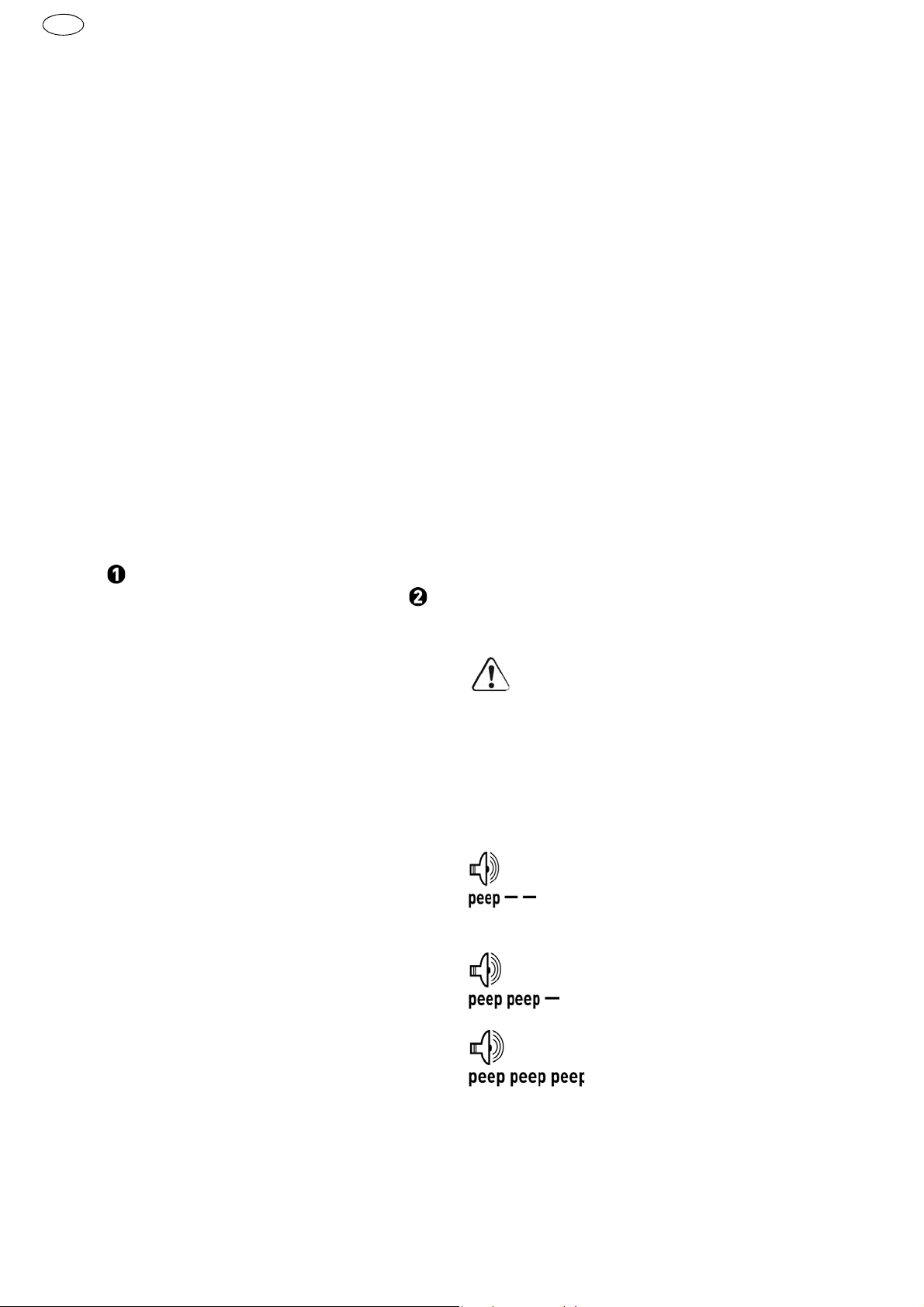
DWC
DK
Isætning af bælte med skruer
Før bæltet med skruerne
[10-3]
gennem magasinets nedre føring og så gennem slædeføringen, hvor skruen falder på plads i skrueklar stilling.
Træk let i bæltet for at tjekke, at det sidder korrekt.
Kontroller, at skrue nr. 1 er i skrueklar position
– jf. fig.
Den ønskede skruedybde indstilles med hjulet
[10-1]
Drej mod højre for at øge skruedybden, drej mod
[10]
.
.
venstre for at mindske den. Den aktuelle indstilling kan ses på indstillingsviseren
[10-2]
.
Efter afsluttet indstilling foretag en prøveskruning
og juster dybden efter behov med hjulet
[10-1]
. Enhver ændring af indstillingen svarer til, at anslaget
flyttes med ±0,1 mm.
Det anbefales at slå automatisk skruning til – jf.
pkt. 9.1 b).
Fjernelse af bæltet
Bæltet fjernes ved blot at trække det opad (fig.
[11]
)) eller ved at trykke transporthåndtaget
og trække bæltet samtidigt nedad (fig.
[11]
).
10 Arbejdsvejledning
– Magasinet må ikke befinde sig i nærheden af
dybdeanslaget!
– Alle skruer skal færdigspændes. Pauser eller
mindsket pres under fastspændingen kan medføre dårlig funktion af skruemaskinen.
– Bælter med reserveskruer udskiftes kun, mens
maskinen er slukket.
– Magasinet må ikke anvendes på andre måder,
end den som er beskrevet i denne brugervejled-
ning.
– Brug kun originale skruebits.
– Brug kun originale skruebælter.
– Skruebælter opbevares altid i original emballa-
ge.
– Hold skruemaskinen vinkelret på den plade, der
skal skrues fast.
10.1 Vedligeholdelse af magasinet
Magasinet er stort set vedligeholdelsesfrit. Efter
længerevarende brug anbefales det at rengøre magasinet med trykluft.
Magasinets forsatsenhed må smøres ved slædeføringen – se fig.
[12b]
.
Forud for rengøringen afmonteres magasinet som
beskrevet ovenfor.
Forud for rengøringen fjernes skruebæltet fra magasinet som beskrevet i afsnittet 9.4 <Fjernelse af
bæltet>.
Afmonter magasinet fra skruemaskinen.
Afmontering af slæde
Pres dybdeanslaget
nappen
[12-1]
er på niveau med mærket for af-
montering af slæden
Tryk på låseknappen
slæden fra magasinet – jf. fig.
Tryk på den knap
deanslaget – jf. fig.
[9-2]
ind i huset, så låsek-
[12-2]
[12-1]
– jf. fig.
og fjern samtidigt
[12b]
[9-1]
og frigør samtidigt dyb-
[12c]
.
[12a]
.
.
Afmontering af transporthåndtaget
Tryk på knappen
[13a]
.
Den løse knap
porthåndtaget
fra slæden (fig.
De enkelte dele rengøres, defekte eller slidte
[13-1]
[13-1]
[13-2]
[13c]
og skub den ud – jf. fig.
(fig.
[13b]
) samt trans-
og fjederen
[13-3]
fjernes
).
dele udskiftes og maskinen samles i omvendt
rækkefølge.
Sørg for korrekt placering af knappens fjeder
[13-3]
i transporthåndtaget under monteringen af transporthåndtaget på slæden. Forkert montering kan medføre fejl i flytning af
bæltet.
10.2 Akustiske advarselssignaler
Akustiske advarselssignaler høres ved følgende
driftstilstande, og maskinen slår fra:
Batteriet er tomt eller maskinen
overbelastet.
– Skift batteri.
– Belast maskinen mindre.
Maskinen er overophedet.
– Efter afkøling kan maskinen ta-
ges i brug igen.
Li-ion-batteriet er overophedet
eller defekt.
– Lad batteriet afkøle, og kontroller
dets funktionsevne med batteriladeren.
50
Page 51
11 Vedligeholdelse og pleje
ADVARSEL
Risiko for kvæstelser, elektrisk stød
Fjern altid batteriet før service- og vedligeholdelsesarbejde!
Vedligeholdelses- og reparationsarbejde, der
kræver, at motorhuset åbnes, må kun foretages
af et autoriseret serviceværksted.
EKAT
1
Kundeservice og reparationer
udføres af producenten eller serviceværksteder: Nærmeste adresse finder
De på: www.festool.dk/service
4
Brug kun originale Festool-reservedele! Best.-nr. finder De på:
5
3
2
www.festool.dk/service
må kun
DWC
DK
Overhold følgende anvisninger:
– Sørg for, at ventilationsåbningerne på elværktø-
jet er ublokerede og rene, så kølingen fungerer.
– Sørg for at holde tilslutningskontakterne på el-
værktøjet, laderen og akkuen rene.
Følg anvisningerne, der følger med batteriet,
ved vedligeholdelse, pleje, bortskaffelse og
transport af batteriet!
12 Miljø
Apparatet må ikke bortskaffes med
almindeligt husholdningsaffald!
parater, tilbehør og emballage skal
bortskaffes miljømæssigt korrekt på
en kommunal genbrugsstation. Gældende nationale forskrifter skal overholdes.
Kun EU:
Ifølge Rådets direktiv om affald af elektrisk
og elektronisk udstyr og gennemførelse til national
ret skal gammelt elværktøj indsamles separat og
afleveres til miljøvenlig genvinding.
Informationer om REACh:
www.festool.com/reach
Ap-
51
Page 52
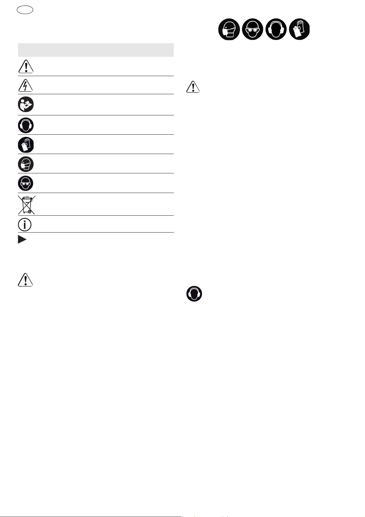
DWC
N
Originalbruksanvisning
1Symboler
Symbol Betydning
Advarsel om generell fare
Advarsel om elektrisk støt
Brukerhåndbok, les sikkerhetsinformasjonen!
Bruk hørselvern!
Bruk vernehansker.
Bruk åndedrettsvern!
Bruk vernebriller!
Må ikke kastes i husholdningsavfallet.
Tips, merknad
Veiledning
–
Bruk egnet personlig verneutstyr:
hørselvern,
vernebriller og støvmaske når det oppstår støv
under arbeidet, vernehansker ved bearbeiding av
ru materialer og når verktøy skal byttes.
FORSIKTIG! Elektroverktøyet kan blokkeres
og forårsake plutselig rekyl!
Slå det av
umiddelbart!
–
Hold godt tak i elektroverktøyet. Still inn korrekt dreiemoment ved skruing. Vær forberedt
på et høyt reaksjonsmoment,
som gjør at elektroverktøyet dreier og kan forårsake personskader.
Ikke bruk elektroverktøyet i regn eller fuktige
–
omgivelser.
Fuktighet i elektroverktøyet kan
medføre kortslutning og brann.
– Ikke hold av-/på-knappen inne over lengre tid!
– Ved tilkopling av beholderen og batteridrevet
skrumaskinen oppstår det en maskin, for hvilken
gjelder instruksjoner og tiltak for et batteridrevet
skrumaskin.
2.3 Utslippsverdier
Typiske verdier (beregnet etter EN 60745):
2 Sikkerhetsregler
2.1 Generell sikkerhetsinformasjon
Advarsel!
visninger.
ikke overholdes, kan det føre til elektrisk
støt, brann og/eller alvorlige personskader.
Oppbevar alle sikkerhetsmerknader og anvisninger for fremtidig bruk.
Nedenfor brukes uttrykket "elektroverktøy". Det viser til nettdrevne elektroverktøy (med ledning) og
batteridrevne elektroverktøy (uten ledning).
2.2 Sikkerhetsanvisninger som er spesifikke for maskinen
–
Maskinen må bare holdes i de isolerte gripeflatene når du utfører arbeid der skruen kan komme til å treffe skjulte strømledninger.
skruen kommer i kontakt med en strømførende
ledning, kan metalldeler på maskinen settes under spenning. Det kan medføre elektrisk støt.
–
Bruk søkeutstyr for å lokalisere skjulte ledninger/rør eller henvend deg til din strøm-, vanneller gassleverandør.
mer i kontakt med en strømførende ledning, kan
dette føre til brann og elektrisk støt. Skader på
gassledninger kan føre til eksplosjoner. Boring i
vannrør kan føre til materielle skader.
Les alle sikkerhetsregler og an-
Hvis advarslene og anvisningene
Dersom
Dersom verktøyet kom-
Lydtrykknivå LPA = 78 dB(A)
Lydeffektnivå LWA = 89 dB(A)
Usikkerhet K = 3 dB
Bruk hørselvern
Svingningsemisjonsverdi ah (vektorsum fra tre retninger) og usikkerhet K beregnet i henhold til EN
60745:
DWC 18-2500
DWC 18-4500
ah = 2,8 m/s
K = 1,5 m/s
ah = 3,5 m/s
K = 1,5 m/s
2
2
2
2
De angitte emisjonsverdiene (vibrasjon, støy)
– brukes til å sammenligne maskiner,
– men kan også brukes til en foreløpig vurdering av
vibrasjons- og støybelastning ved bruk,
– og representerer de viktigste bruksområdene for
elektroverktøyet.
En økning er mulig ved annet bruk, med annet innsatsverktøy eller ved utilstrekkelig vedlikehold.
Vær oppmerksom på maskinens tomgangs- og
stillstandsperioder!
52
Page 53

DWC
3 Riktig bruk
Trockenbauschauber geeignet für folgende
Schraubarbeiten:
DWC 18-2500
– Gipsplate på metall- og trekonstruksjon - Hurtig-
skruer med freseribber
– Sponplater/OSB på trekonstruksjon - Tre- og
sponplateskruer inntil Ø 5 mm
DWC 18-4500
– Gipsplate på metallprofiler (≤ 0,88 mm) - Hurtig-
skruer med fine gjenger
– Gipsplate på metallprofiler (≤ 2,25 mm) - Hurtig-
skruer med borspiss
– Gipsplate på trekonstruksjon - Hurtigskruer
medgrove gjenger
Ved ikke-forskriftsmessig bruk bærer brukeren ansvaret, under dette regnes også industriell, kontinuerlig bruk.
4Tekniske data
Batteridrevet skrumaskin for gipskartong DWC18-2500 DWC18-4500
Motorspenning 18 V 18 V
Omdreininger på tomgang* 0 - 2500 min
Dreiemoment (myk/hard) 7 / 18 Nm 5 / 14 Nm
-1
0 - 4500 min
N
-1
Verktøyets festning i spindelen 1/4 ’’ DIN 3126 / ISO 1173 1/4 ’’ DIN 3126 / ISO 1173
Maksimalt håndterbar skruelengde 55 mm 55 mm
Vekt (uten batteri) 1,2 kg
Vekt med dybdestopp (uten batteri) 1,3 kg
Vekt med beholder (uten batteri) 1,6 kg
* Opplysninger om turtall med fulladet batteri.
5Apparatets deler
[1-1]
Bitsdepot
7 Innstillinger
FORSIKTIG
[1-2]
[1-3]
[1-4]
[1-5]
[1-6]
[1-7]
Avbildet eller beskrevet tilbehør kan avvike fra tilbehøret som følger med.
På/av-knapp
Høyre/venstre-bryter
Bryter AUTO/MAN
Dybdestopp
Ruuvipala
Isolerte gripeflater (område i grått)
Fare for personskade
Innstillinger må kun foretas når elektroverktøyet
er slått av!
7.1 Endre dreieretning [1-3]
• Bryteren mot venstre = høyregang
• Bryteren mot høyre = venstregang
8 Verktøyfeste, forsats
De oppgitte illustrasjonene finnes fremst i bruksanvisningen.
ADVARSEL
6 Igangsetting
6.1 Bytte av batteri
Sette inn batteri [2 A]
Ta ut batteri [2 B]
Batteriet er klart til bruk ved levering og kan lades opp til enhver tid.
Fare for personskade
Ta ut batteriet før det foretas arbeider på maskinen!
8.1 Bitsholder
Bitsholderen muliggjører et hurtig skift av bits.
53
Page 54

DWC
N
FORSIKTIG
Varmt og skarpt verktøy
Fare for personskade
Unngå bruk av stumpe og defekte verktøy.
Bruk vernehansker.
Montering av bitsholder
Bryteren
Bitsholderen
skantete åpningen til spindelen
I holderen skal det festes bitsen
Etterpå sett dybdestoppet på girboksen slik,
som er beskrevet i punkt 9.2.
Demontering av bitsholder
Ta dybdestoppet av, som beskrevet i punkt 9.2.
Ta holderen ut fra spindelen med makt.
8.2 Bitsutskifting
Til bitsutskifting
[1-5]
.
Sett dybdestoppet på bitsen (se bildet
Ved å støtte dybdestoppet med bitsen og en
samtidig trekk, kan du ta bitsen ut.
Etterpå sett en ny bits i holderen.
[1-4]
skal stilles inn i posisjon MAN.
[4-2]
skal settes fast på den sek-
[4-4]
[4-3]
[1-6]
kan du bruker dybdestoppet
.
.
[4b]
c)
Sett venstredrift til maskinen med bryteren
3]
.
Etter at maskinen er slått på, slå av/på bryteren
på
[1-2]
.
Bryteren MAN/AUTO
[1-4]
er i en tilfeldig posi-
[1-
sjon.
Med av/på bryteren
[1-2]
kan du flytende regulere
omdreininger.
Hvis venstredrift er innstilt med bryteren
[1-2]
,
kan skrumaskinen slås på med et trykk på bryteren – uten ekstra trykk på bitsen.
Derfor, til å skrue skruer av, er det ikke nødvendig å demontere dybdestoppet.
9.2 Dybdestopp
Ved å dreie dybdestoppet
dybden på skruing – se bildet
[1-5]
kan det innstilles
[5]
. Innstilling nøyak-
tighet er cirka ± 0,1 mm.
Venstredreiing skruen skrues dypere
Høyredreiing skruen skrues i en mindre dybde
Etter dybdeinnstilling sett en skrue, som en prøve,
.
og følgende innstill dybden.
Montering av dybdestopp
Sett dybdestoppet
[4-1]
på girboksen
[4-5]
inn-
til det settes på plass og du hører en klikk.
9 Arbeid med maskinen
9.1 Slå på og av [1-2]
Med et enkelt trykk på av/på bryteren
kommer ikke maskinen i gang –
maskinens defekt
Etter skruing fast på den ønskende dybden, slås
!
det betyr ikke
maskinen av selv!
Det er flere måter hvordan maskinen kan slås på:
a)
Sett høyredrift til maskinen med bryteren
Bryteren
Etter at maskinen har blitt slått på, slå av/på
bryteren
[1-4]
skal stilles inn i posisjon MAN.
[1-2]
på og samtidig trykk med bitsen
på skruen.
Med av/på bryteren
[1-2]
kan du fl ytende regulere
omdreininger.
b)
Sett høyredrift til maskinen med bryteren
Innstill bryteren
Hvis du vil slå maskinen på, trykk bitsen på
[1-4]
i posisjon AUTO.
skruen.
Det er ikke nødvendig å slå av/på bryteren
Maksimale omdreininger er forevalget automatisk.
54
[1-3]
[1-3]
[1-2]
[1-2]
på.
Demontering av dybdestopp
Ta dybdestoppet av girboksen med makt.
9.3 Krok for henging og klemme
Med klemmen
[6-1]
kan du feste skrumaskinen
foreløpig på arbeidsklær – det kan festes med
[6-2]
skruen
på maskinen på den venstre eller høyre siden, og derfor passer det både for høyrehendte
og keivhendte – se bildet
Skrumaskinen er utstyrt med en krok
[6]
.
[7-1]
ner til spredte henging av maskinen. Det kan festes
.
på maskinens venstre eller høyre side, med hjelp av
skruen
[7-2]
se bildet
[7]
.
9.4 Skruebeholder
Beholder muliggjører en kontinuerlig arbeid, uten
unødvendige pauser.
Hvordan beholderen settes på
Først ta dybdestoppet
[4-1]
, bitsholderen
og bitsen av, som beskrevet i punket 8.
.
Bryteren
Sett bitsen
[1-4]
skal stilles inn i posisjon MAN.
[8-1]
fast til den sekskantete åpnin-
gen til spindelen.
Etterpå sett beholderen på girboksen. Beholderen må settes fast på girboksen med en klikk.
Beholderen kan innstilles i vinkler på 30°.
somtje-
[4-2]
Page 55
Hvordan beholderen tas av
Ta beholderen av fra girboksen med et kraftig
men forsiktig trekk.
Lengdeinnstilling på skrue
Med et trekk på trykket
[9-2]
stikkes ut eller inn og slik kan det innstil-
[9-1]
kan dybdestoppet
les den ønskende skruelengden.
Den innstilte dybden på skruer avleses på sidene til
stoppet
[9-3]
.
Innstilling av bånd med skruer
Dra båndet med skruer
[10-3]
gjennom den nedre ledningen til beholderen og etterpå gjennom ledningen til skinner, hvor skruen settes i
arbeidsposisjonen.
Sjekk med et lett trekk på båndet om båndet er
satt riktig.
Sjekk om den første skruen er i skruingsakselen – se bildet.
Innstill den nødvendige dybden på skruing med
hjulet
Med høyrederiing settes skruene dypere, med
[10-1]
.
[10]
.
venstredreiing trekkes skruene ut. På forstilling
indikatoren
[10-2]
kan det avleses den aktuelle
posisjonen på innstilling.
Etter innstilling sett en skrue, som en prøve, og
eventuelt innstill dybden med hjulet
[10-1]
. Hver
endring i innstiling betyr skifting av stoppet med ±
0,1 mm.
Vi anbefaler å skrue i en automatisk modus – se
punkt 9.1 b).
Hvordan å ta ut bånd
Båndet tas ut med et trekk i oppretning (bildet
[11]
) eller med et trykk på transportspaken
og med et sammentidig trekk på båndet i nedretning (bildet
[11]
).
10 Arbeidstiltak
– Beholderen skal ikke holdes i området til dybde-
stoppet!
– Hver skruing fast av skruen må fullføres. Hvis
skruing er brudd av eller trykket er løsnet ved
DWC
N
skruing fast, kan dette føre til en ikke tilfredstillende funksjon på maskinen.
– Bånd med skruer kan skiftes kun, når maskinen
er slått av.
– I ingen fall skal du bruke beholderen på en annen
måte enn på måten, som er beskrevet i denne
bruksanvisningen.
– Bruk kun originale skruebits.
– Bruk kun originale bånd med skruer.
– Bånd med skruer skal alltid lagres i den originale
pakken.
– Alltid arbeid i en rett vinkel imot festingsplaten.
10.1 Beholderens vedlikehold
Beholderen krever ikke noen vedlikehold. Etter en
langvarig bruk anbefaler vi å rense den med trykkluft.
Beholderen må smøres i områet ved sledeføringen
– se figur
[12b]
.
Demonter beholderen før rensing slik, som er beskrevet i tidligere punkter.
Ta båndet med skruer ut av beholderen før rensing
slik, som er beskrevet i artikkelen 9.4 <Hvordan å ta
ut bånd>.
Ta beholderen av skrumaskinen.
Demontering av skinner
Trykk dybdestoppet
stopptrykket
[12-1]
for demontering av skinner
[12a]
.
Trykk stopptrykket
ner ut fra beholderen – se bildet
Trykk det trykket
stoppet – se bildet
[9-2]
i boksen slik, at
er på nivået av en merking
[12-2]
[12-1]
[9-1]
[12c]
og samtidig ta skin-
og samtidig løsne dybde-
.
- se bildet
[12b]
.
Demontering av transportspake
Trykk trykket
bildet
Ta det løsnet trykket
[13a]
transportspaken
skinner (bildet
Rens de enkle delene, skift skadete elle slite
[13-1]
.
og samtidig ta det ut – se
[13-2]
[13c]
[13-1]
).
(bildet
og fjæret
[13-3]
[13b]
) med
ut fra
deler og monter alt i en omvendt rekkefølge.
Ved tilbakemontering av transport spaken i
skinner, pass på, at du setter fjæret til trykket
[13-3]
i transportspaken på en riktig måte.
Uriktig montering kan føre til en dårlig funksjon på transportsbåndet.
10.2 Akustiske varselsignaler
Et lydsignal avgis ved følgende driftstilstander, og
maskinen slår seg av:
55
Page 56
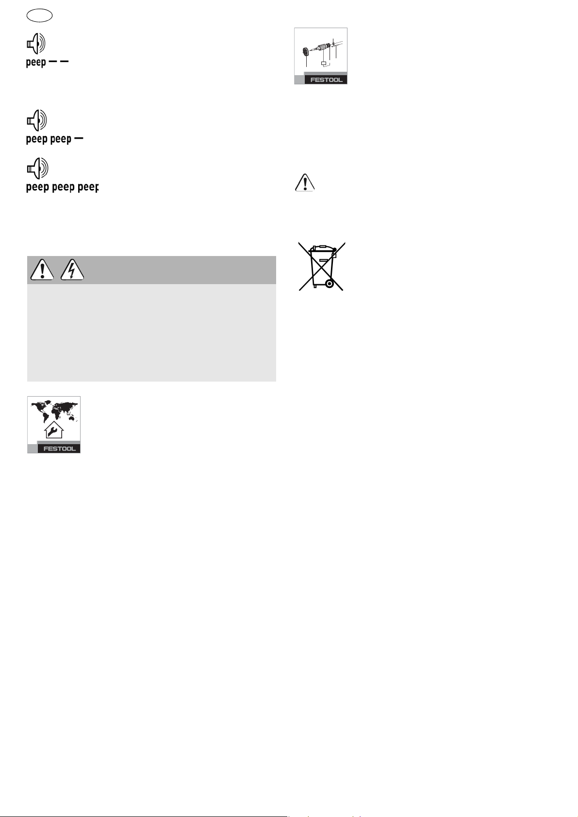
N
EKAT
1
2
3
5
4
DWC
Batteriet er tomt eller maskinen
er overbelastet.
– Bytt batteri.
– Reduser belastningen på maski-
nen.
Maskinen er overopphetet.
– Maskinen kan brukes videre etter
at den er avkjølt.
Li-ion-batteriet er overopphetet
eller defekt.
– Bruk laderen til å kontrollere om
batteriet fungerer som det skal
når det er avkjølt.
11 Vedlikehold og pleie
ADVARSEL
Skaderisiko. Elektrisk støt
Ta ut batteriet før vedlikeholds-/reparasjonsarbeider på maskinen.
Alle vedlikeholds- og reparasjonsarbeider som
krever at motorhuset åpnes, skal kun gjennomføres av et autorisert kundeservice-verksted.
Bruk kun originale Festool-reservedeler! Best.nr. finner du under:
www.festool.com/service
Ta hensyn til følgende:
– Hold lufteåpningene på elektroverktøyet åpne og
rene, slik at kjølingen fungerer.
– Hold tilkoblingskontaktene på elektroverktøyet,
laderen og batteriet rene.
Når batteriet skal vedlikeholdes, kasseres
eller transporteres, må du følge anvisninge-
ne som følger med batterie.
12 Miljø
Apparatet skal ikke kastes i restavfallet!
sje skal sorteres til gjenvinning. Ta
hensyn til gjeldende nasjonale forskrifter.
Kun EU:
I henhold til EU-direktivet om kasserte
elektriske og elektroniske produkter og direktivets
iverksetting i nasjonal rett må elektroverktøy som
ikke lenger skal brukes, samles separat og returneres til et miljøvennlig gjenvinningsanlegg.
Informasjon om REACh:
Apparater, tilbehør og emballa-
www.festool.com/reach
Kundeservice og reparasjoner
skal
kun utføres av produsenten eller serviceverksteder: Du finner nærmeste
adresse under:
www.festool.com/service
56
Page 57
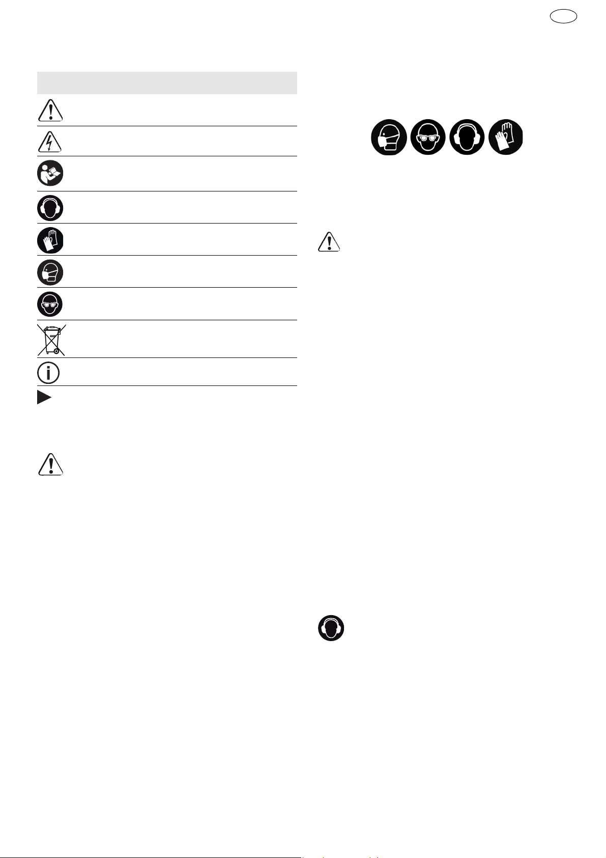
Manual de instruções original
1Símbolos
Símbolo Significado
Advertência de perigo geral
Advertência de choque eléctrico
Ler Manual de instruções, indicações de
segurança!
Usar protecção auditiva!
Usar luvas de protecção!
Usar máscara de protecção!
Usar óculos de protecção!
Não deite no lixo doméstico.
Conselho, indicação
Instruções de manuseamento
2 Indicações de segurança
2.1 Instruções gerais de segurança
Advertência!
segurança e instruções.
das indicações de segurança e instruções
pode dar origem a um choque eléctrico, um incêndio e/ou a ferimentos graves.
Guarde todas as indicações de segurança e instruções para futura referência.
O termo "ferramenta eléctrica" utilizado nas indicação de segurança refere-se a ferramentas eléctricas utilizadas com ligação à rede (com cabo de
rede) e com acumulador (sem cabo de rede).
2.2 Instruções de segurança específicas da
máquina
–
Segure a ferramenta apenas pelas pegas isoladas, caso efectue trabalhos em que o parafuso
possa atingir linhas de corrente ocultas.
tacto do parafuso com uma linha condutora de
corrente também pode colocar as peças metálicas da ferramenta sob tensão, conduzindo a
electrocussão.
–
Utilize detectores adequados, para encontrar
linhas de alimentação ocultas ou consulte a em-
Leia todas as indicações de
A não observação
O con-
presa de distribuição local.
DWC
O contacto da ferra-
P
menta de trabalho com uma linha condutora de
corrente pode conduzir a fogo e choques eléctricos. A danificação de um tubo de gás pode originar uma explosão. A infiltração num tubo de
água origina danos materiais.
–
Use equipamentos de protecção pessoal adequados:
protecção auditiva, óculos de protecção,
máscara de pó no caso de trabalhos em que seja
produzido pó, luvas de protecção ao trabalhar
com materiais rugosos e ao mudar ferramentas.
CUIDADO! A ferramenta eléctrica pode bloquear e causar repentinamente um contragolpe!
–
Segure a ferramenta firmemente na mão. Ao
Desligar imediatamente!
aparafusar, ajuste correctamente o binário. Esteja preparado para um elevado binário de reacção
que poderá fazer com que a ferramenta
eléctrica rode, dando origem a ferimentos.
–
Não utilize a ferramenta eléctrica à chuva ou em
ambientes humidos.
Humidade na ferramenta
eléctrica poderá dar origem a um curto-circuito
e incêndio.
– Não bloquear o interruptor de ligar/desligar per-
manentemente!
– Ao juntar o depósito e a aparafusadora de acu-
mulador cria-se um aparelho, para o qual são válidas as normas e as instruções de segurança da
aparafusadora de acumulador.
2.3 Valores de emissão
Os valores determinados de acordo com a EN 60745
são tipicamente:
Nível de pressão acústica LPA = 78 dB(A)
Nível de potência acústica L
= 89 dB(A)
WA
Incerteza K = 3 dB
Usar protecção auditiva!
Nível de emissão de vibrações ah (soma vectorial
em três direcções) e incerteza K determinados de
acordo com a norma NE 60745:
DWC 18-2500
DWC 18-4500
ah = 2,8 m/s
K = 1,5 m/s
ah = 3,5 m/s
K = 1,5 m/s
2
2
2
2
Os valores de emissão indicados (vibração, ruído)
57
Page 58

DWC
P
– servem de comparativo de ferramentas,
– são também adequados para uma avaliação pro-
visória do coeficiente de vibrações e do nível de
ruído durante a aplicação,
– representam as aplicações principais da ferra-
menta eléctrica.
Aumento possível no caso de outras aplicações,
com outras ferramentas de trabalho ou manutenção insuficiente. Observar os tempos de trabalho
em vazio e de paragem da ferramenta!
3 Utilização conforme as disposi-
ções
A aparafusadora de montagem destina-se aos seguintes trabalhos:
DWC 18-2500
– Painéis de gesso reforçados com fibras sobre
construções de metal e madeira - de parede com
filetes
– Painéis de aglomerado/OSB – painel de partícu-
las de madeira orientadas – sobre construção de
madeira - Parafusos para construções de madeira e painéis de aglomerado até dia. 5 mm
DWC 18-4500
– Painéis de gesso cartonado sobre calhas perfila-
das de metal (≤ 0,88 mm) - Parafusos de parede
com rosca fina
– Painéis de gesso cartonado sobre calhas perfila-
das de metal (≤ 2,25 mm) - Parafusos de parede
com broca
– Painéis de gesso cartonado sobre construções
de madeira - Parafusos de parede com rosca
grossa
Em caso de utilização incorrecta, a responsabilidade é do utilizador; de uma utilização
incorrecta também faz parte um funcionamento industrial contínuo.
4 Dados técnicos
Aparafusadora de acumulador para gesso
cartonado
Tensão do motor 18 V 18 V
Rotações em vazio* 0 - 2500 min
Binário (brando / duro) 7 / 18 Nm 5 / 14 Nm
Fixação de ferramentas no fuso 1/4 ’’ DIN 3126 / ISO 1173 1/4 ’’ DIN 3126 / ISO 1173
Máximo comprimento do parafuso que pode ser
processado
Peso (sem acumulador) 1,2 kg
Peso com batente de profundidade (sem acumu-
lador)
Peso com depósito (sem acumulador) 1,6 kg
* Dados sobre o número de rotações com o acumulador completamente carregado.
5 Componentes da ferramenta
[1-1]
[1-2]
[1-3]
[1-4]
[1-5]
[1-6]
[1-7]
Suporte para bits
Interruptor de activação/desactivação
Interruptor Para a direita/Para a
esquerda
Interruptor AUTO/MAN
Batente de profundidade
Bit
Áreas de pega isoladas (área sombreada
a cinzento)
DWC18-2500 DWC18-4500
-1
55 mm 55 mm
1,3 kg
Alguns dos acessórios ilustrados ou descritos não
fazem parte do âmbito de fornecimento.
As figuras indicadas encontram-se no início do manual de instruções.
0 - 4500 min
-1
6 Colocação em funcionamento
6.1 Substituir o acumulador
Colocar o acumulador [2 A]
Retirar o acumulador [2 B]
Na entrega, o acumulador está imediatamente
pronto a funcionar e pode ser carregado a qualquer momento.
58
Page 59

7Ajustes
CUIDADO
Perigo de ferimento
Efectuar os ajustes apenas com a ferramenta
eléctrica desligada!
DWC
Coloque o batente de profundidade no bit (veja a
Figura
Ao atravessar o batente de profundidade com o
[4b]
.
bit e ao puxar, simultaneamente, é possível retirar o bit.
Depois coloque um bit novo no porta-ferramentas.
P
7.1 Alterar sentido de rotação [1-3]
• Interruptor para a esquerda = rotação para a direita
• Interruptor para a direita = rotação para a esquerda
8 Fixação de ferramentas, adapta-
dores
ATENÇÃO
Perigo de ferimentos
Antes de efectuar qualquer trabalho na ferramenta, retirar o acumulador da ferramenta!
8.1 Porta-ferramentas
O porta-ferramentas permite uma mudança rápida
de bits.
CUIDADO
Ferramenta quente e afiada
Perigo de ferimento
Não devem ser utilizadas ferramentas de trabalho embotadas e defeituosas!
Usar luvas de protecção.
Montagem do porta-ferramentas
Coloque o interruptor
Coloque o porta-ferramentas
no orifício hexagonal do fuso
Fixe o bit
Depois, coloque o batente de profundidade na
[4-3]
no porta-ferramentas.
caixa de câmbio, como descrito no ponto 9.2.
Desmontagem do porta-ferramentas
Retire o batente de profundidade conforme a
descrição no ponto 9.2.
Retire o porta-ferramentas, com força, do orifício do furo.
8.2 Substituição do bit
Para mudar o bit
fundidade
[1-5]
[1-6]
.
[1-4]
na posição MAN.
[4-2]
no batente
[4-4]
.
, pode usar o batente de pro-
9Trabalhos com a ferramenta
9.1 Ligar/desligar [1-2]
Depois coloque um bit novo no porta-ferramentas
[1-2]
e a máquina não se ligará –
ta de um defeito da máquina
Depois de aparafusar até à profundidade dese-
!
jada, a máquina desligar-se-á automaticamente!
A máquina pode ser ligada de várias maneiras:
a)
Ligue a rotação para a direita com o interruptor
[1-3]
.
Coloque o interruptor
Para ligar a máquina, ligue o interruptor
[1-4]
na posição MAN.
e, simultaneamente, empurre o parafuso com o
bit.
Com o interruptor
[1-2]
, é possível regular as rota-
ções continuamente.
b)
Ligue a rotação para a direita com o interruptor
[1-3]
.
Coloque o interruptor
A máquina ligar-se-á, se empurrar o parafuso
[1-4]
na posição AUTO.
com o bit.
Não é necessário ligar o interruptor
ções máximas são ajustadas automaticamente.
c)
Ligue a rotação para a esquerda com o interruptor
[1-3]
.
Depois de ligar a máquina, ligue o interruptor
[1-2]
.
O interruptor MAN/AUTO
[1-4]
qualquer posição.
[1-2]
Com o interruptor
, é possível regular as rota-
ções continuamente.
Se a rotação para a esquerda for definida com o
interruptor
[1-2],
será possível iniciar o funcionamento da aparafusadora simplesmente ao
pressionar o interruptor – sem uma pressão
adicional sobre o bit.
não se tra-
[1-2]
[1-2]
! As rota-
encontra-se em
59
Page 60

DWC
P
Sendo assim, para desaparafusar os parafusos
não é necessário desmontar o batente de profundidade.
9.2 Batente de profundidade
Ao rodar o batente de profundidade é possível ajustar a profundidade do aparafusamento – veja a Figura
[5]
. A exactidão do ajuste é de, aproximada-
mente, ± 0,1 mm.
Rotação para a
o parafuso afunda-se mais.
esquerda
Rotação para a
o parafuso afunda-se menos
direita
Depois de ajustar a profundidade, coloque um pa-
rafuso para a testar e ajuste a profundidade melhor.
Montagem do batente de profundidade
Coloque o batente de profundidade
xa de câmbio
[4-5]
, até ouvir um clique.
[4-1]
na cai-
Desmontagem do batente de profundidade
Retire o batente da caixa de câmbio com força.
9.3 Gancho para suspender e abraçadeira
para a fixação ao cinto
A abraçadeira para a fixação ao cinto
[6-1]
permite
a fixação de curta duração do aparelho à roupa de
serviço – é possível fixá-lo com o parafuso
[6-2]
namáquina de lado esquerdo ou direito. A máquina é,
assim, apropriada para destros e para canhotos –
veja a Figura
A aparafusadora é equipada com um gancho
[6]
.
[7-1]
destinado para a eventual suspensão da máquina.
O gancho pode ser fixado na máquina de lado esquerdo ou direito, com a ajuda do parafuso
veja a Figura
[7]
.
[7-2]
-
9.4 Depósito de parafusos
O depósito permite trabalhar continuamente, sem
pausas desnecessárias.
Colocar do depósito
Retire primeiro o batente de profundidade
1]
, o porta-ferramentas
[4-2]
e o bit, como des-
[4-
crito no ponto 8.
Coloque o interruptor
Coloque o bit
[8-1]
[1-4]
na posição MAN.
no batente no orifício hexa-
gonal do fuso.
Depois, coloque o depósito na caixa de câmbio.
Ao colocar o depósito nas saliências da caixa de
câmbio, deve-se ouvir um clique.
É possível mudar a posição do por 30°.
Retirar o depósito
Retire o depósito da caixa de câmbio, puxandoo com força, cuidadosamente.
Ajuste do comprimento do parafuso
Pressionando o botão
[9-1]
, é possível retirar e
introduzir o batente de profundidade
ajustar, assim, o comprimento desejado de parafusos.
O comprimento ajustado de parafusos pode ser lido
nas partes laterais do batente
[9-3]
.
Introdução do cinto com parafusos
Primeiro, introduza o cinto com parafusos
3]
na parte inferior do depósito e depois no trenó, onde o parafuso encaixa na posição de trabalho.
Verifique a colocação segura do cinto, puxandoo ligeiramente.
Verifique se o primeiro parafuso se encontra no
eixo do aparafusamento – veja a Figura
Ajuste a profundidade necessária do aparafusamento com a roda
Rodando para a direita, os parafusos encaixam-
[10-1]
.
se mais fundo, rodando para a esquerda menos.
A posição actual do ajuste pode ser lida no indicador da pré-selecção
[10-2]
.
Depois do ajuste, coloque um parafuso para testar
e ajuste a profundidade melhor com a roda
Cada alteração do ajuste corresponde à deslocação
,
do batente em ± 0,1 mm.
Aconselhamos aparafusar no regime automático – veja o ponto 9.1 b).
Retirar o cinto
O cinto retira-se, puxando-o apenas na direcção
para cima (Figura
[11]
) ou pressionando a
alavanca de transporte e puxando o cinto na direcção para baixo, simultaneamente (Figura
[11]
).
10 Instruções de trabalho
– O depósito não pode ser segurado na área do ba-
tente de profundidade!
– Sempre é necessário terminar a fixação de para-
fusos. Uma fixação interrompida ou uma pressão
[9-2]
[10-
[10]
[10-1]
e
.
60
Page 61

solta durante a fixação pode causar um funcionamento insuficiente da máquina.
– Os cintos com parafusos sobressalentes poderão
ser substituídos apenas se a máquina estiver
desligada.
– Nunca use o depósito de uma forma diferente da
forma descrita neste Manual de uso.
– Use apenas os bits aparafusadores originais.
– Use apenas os parafusos de cinto originais.
– Armazene os cintos com parafusos sempre na
embalagem original.
– Trabalhe sempre em ângulo recto contra a placa
fixada.
10.1 Manutenção do depósito
Em princípio, o depósito não necessita de nenhuma
manutenção. Depois de uso prolongado, aconselhamos limpá-lo com ar de pressão.
O adaptador do depósito de parafusos pode ser lubrificado no respectivo elemento da corrediça – ver
[12b]
ilustração
.
Antes da limpeza, desmonte o depósito, como descrito nos pontos anteriores.
Antes da limpeza, retire o cinto com parafusos do
depósito, como descrito no artigo 9.4 <Retirar o
cinto>.
Retire o depósito da aparafusadora.
Desmontagem do trenó
Empurre o batente de profundidade
[9-2]
para
dentro da caixa de tal forma, que o botão de detentor
para a desmontagem do trenó
gura
Prima o botao de detentor
[12-1]
[12a]
se encontre no nível da marca
[12-2]
– veja a Fi-
.
[12-1]
e, simultanea-
mente, retire o treno do deposito – veja a Figura
[12b]
.
Prima o botão
batente de profundidade – veja a Figura
[9-1]
e, simultaneamente, solte o
[12c]
.
Desmontagem da alavanca de transporte
Prima o botão
te – veja a Figura
Retire o botão solto
alavanca de transporte
do treno (Figura
Limpe as peças individuais, substitua as peças
[13-1]
[13a]
[13c]
e retire-o simultaneamen-
.
[13-1]
(Figura
[13-2]
[13b]
e a mola
) com a
[13-3]
).
defeituosas ou gastas e volte a montá-las em
sequência invertida.
DWC
P
Ao voltar a montar a alavanca de transporte
no trenó, preste atenção à colocação correcta da mola do botão
[13-3]
na alavanca de
transporte. Uma montagem incorrecta pode
causar um mau funcionamento do transpor-
te de cintos.
10.2 Sinais de advertência acústicos
Os sinais de advertência acústicos surgem nos seguintes estados de funcionamento e a ferramenta
desliga-se:
Acumulador descarregado ou ferramenta sobrecarregada.
– Substitua o acumulador.
– Submeta a ferramenta a menos
esforço.
A ferramenta está sobreaquecida.
– Depois de arrefecer, pode voltar a
ser colocada em funcionamento.
O acumulador LiIon está sobreaquecido ou defeituoso.
– Utilizando o carregador, verifique
a capacidade de funcionamento
com o acumulador arrefecido.
11 Manutenção e conservação
ATENÇÃO
Perigo de ferimentos, choque eléctrico
Antes de efectuar qualquer trabalho de manutenção e de conservação, retire sempre o acumulador da ferramenta!
Todos os trabalhos de manutenção e reparação,
que exigem uma abertura da carcaça do motor,
apenas podem ser efectuados por uma oficina
de Serviço Após-venda autorizada.
Serviço Após-venda e Reparação
nas através do fabricante ou das oficinas de serviço: endereço mais próximo
em: www.festool.com/service
EKAT
4
Utilizar apenas peças sobresselentes
originais da Festool! Referência em:
5
3
2
1
www.festool.com/service
Observar as seguintes indicações:
ape-
61
Page 62

DWC
P
– Manter as aberturas de ventilação na ferramenta
eléctrica livres e limpas, de modo a que esteja
assegurado o arrefecimento.
– Manter limpos os contactos de ligação na ferra-
menta eléctrica, carregador e acumulador.
Para manutenção, conservação, eliminação e
transporte do acumulador, ter em atenção as
indicações que companham o acumulador!
12 Meio ambiente
Não deite a ferramenta no lixo doméstico!
acessórios e embalagens para reaproveitamento ecológico. Respeitar as
normas nacionais em vigor.
Encaminhe as ferramentas,
Apenas países da UE:
De acordo com a Directiva
Europeia sobre resíduos de equipamentos eléctricos e electrónicos e a sua transposição para a legislação nacional, as ferramentas electrónicas
usadas devem ser recolhidas separadamente e sujeitas a uma reciclagem que proteja o meio ambiente.
Informações sobre REACh:
www.festool.com/reach
62
Page 63

Оригинальное руководство по
TR066
эксплуатации
1 Символы
СимволЗначение
Предупреждение об общей опасности
Предупреждение об ударе током
Прочтите руководство по эксплуатации
и указания по технике безопасности!
Используйте защитные наушники!
Работайте в защитных перчатках!
DWC
RUS
2.2 Указания по технике безопасности при
пользовании инструментом
–
При выполнении работ вблизи скрытой
электропроводки держите
электроинструмент только за изолированные
части рукоятки.
возможный контакт винта/шурупа с проводкой
под напряжением может вызвать удар
электрическим током через металлические
части инструмента.
–
Используйте подходящие детекторы для
обнаружения скрытой электропроводки,
газо- и водопроводов, или привлеките к
работе специалистов местной
энергоснабжающей компании.
сменного инструмента с э/проводкой может
вызвать удар электрическим током и привести
к возгоранию. Повреждение газопровода
может стать причиной взрыва. Засверливание
или вворачивание шурупа в водопровод станет
причиной материального ущерба.
В противном случае
Контакт
Используйте респиратор!
Работайте в защитных очках!
Не выбрасывать вместе с бытовыми
отходами!
Инструкция, рекомендация
Инструкция по использованию
2 Указания по технике
безопасности
2.1 Общие указания по технике
безопасности
Предупреждение!
по технике безопасности и инструкции.
Неточное соблюдение инструкций и
предупреждений может стать причиной удара
электрическим током, пожара и/или тяжёлых
травм.
Сохраняйте все указания по технике
безопасности и инструкции.
Используемый в указаниях по технике
безопасности термин «электроинструмент»
относится к сетевым электроинструментам (с
сетевым кабелем) и аккумуляторным
электроинструментам (без сетевого кабеля).
Прочтите все указания
–
Используйте средства индивидуальной
защиты:
респиратор в случае образования пыли во
время работы, защитные перчатки при работе
с материалами с шероховатой поверхностью и
при смене рабочего инструмента.
–
Крепко держите электроинструмент в руке.
Правильно отрегулируйте крутящий момент
при завинчивании. Будьте готовы к
появлению высокого реактивного
(обратного) момента,
вращение электроинструмента и стать
причиной травмирования.
Не используйте электроинструмент под
–
дождём или во влажной среде.
влаги внутрь электроинструмента может
привести к короткому замыканию и
возгоранию.
– Не фиксируйте выключатель!
– Соединением насадки автоматической подачи
шурупов с аккумуляторным шуруповертом
возникает оборудование, на которое
распространяются инструкции и указания по
технике безопасности, действующие для
аккумуляторных шуруповертов.
защитные наушники, защитные очки,
ОСТОРОЖНО! Возможна блокировка
электроинструмента и внезапная отдача!
Немедленно выключите!
который может вызвать
Попадание
63
Page 64
RUS
DWC
2.3 Уровни шума
Определенные в соответствии с EN 60745
типовые значения:
3 Применение по назначению
Монтажный шуруповерт предназначен для
нижеуказанных работ:
Уровень звукового
LPA = 78 дБ(A)
давления
Уровень мощности звуковых
LWA = 89 дБ(A)
колебаний
Погрешность K = 3 дБ
Используйте защитные наушники!
Коэффициент эмиссии колебаний ah (сумма
векторов трёх направлений) и погрешность K
рассчитываются согласно EN 60745:
DWC 18-2500
ah = 2,8 m/s
K = 1,5 m/s
DWC 18-4500
ah = 3,5 m/s
K = 1,5 m/s
Указанные значения уровня шума/вибрации
– служат для сравнения инструментов;
– можно также использовать для
предварительной оценки шумовой и
вибрационной нагрузки во время работы;
– отражают основные области применения
электроинструмента.
При использовании машинки в других целях, с
другими сменными (рабочими) инструментами
или в случае их неудовлетворительного
обслуживания шумовая и вибрационная
нагрузки могут возрастать. Соблюдайте значения
времени работы на холостом ходу и времени
перерывов в работе!
DWC 18-2500
– Гипсоволокнистые плиты на металли ческих и
деревянных конструкциях Быстрозаворачиваемые шурупы с
фрезерующими выступами
– ДСП/ОСП на деревянной конструкции Шурупы
по дереву и ДСП диам. до 5 мм
DWC 18-4500
– Гипсокартонные плиты на направляющих из
металлопрофиля (≤ 0,88 мм) -
2
2
2
2
Быстрозаворачиваемые шурупы с мелкой
резьбой
– Гипсокартонные плиты на направляющих из
металлопрофиля (≤ 2,25 мм) Быстрозаворачиваемые шурупы с
самонарезающим острием
– Гипсокартонные плиты на деревянных
конструкциях Быстрозаворачиваемые шурупы
с крупной резьбой
Инструмент сконструирован для
профессионального применения.
Ответственность за использование не по
назначению несет пользователь; сюда
также относятся случаи длительной
эксплуатации в промышленном
производстве (как следствие этого
повреждения и износ).
4 Технические данные
Аккумуляторный шуруповерт для
гипсокартона
Рабочее напряжение 18 В 18 В
Частота вращения холостого хода* 0 - 2500 об/мин 0 - 4500 об/мин
Крутящий момент (мягкий / жёсткий) 7 / 18 Нм 5 / 14 Нм
Зажимное приспособление шпинделя 1/4 ’’ DIN 3126 / ISO 1173 1/4 ’’ DIN 3126 / ISO 1173
Макс. раб. длина шурупа 55 мм 55 мм
Масса (без аккумуляторного) 1,2 кг
Масса с ограничителем глубины (без
аккумуляторного)
Масса с насадкой автоматической подачи
шурупов (без аккумуляторного)
* Данные по частоте вращения указаны для полностью заряженного аккумулятора.
64
DWC18-2500 DWC18-4500
1,3 кг
1,6 кг
Page 65

5 Составные части инструмента
[1-1]
Держатель битов
Осторожно
DWC
RUS
[1-2]
[1-3]
[1-4]
[1-5]
[1-6]
[1-7]
Выключатель
Переключатель направления вращения
Переключатель AUTO/MAN (АВТО/МАН)
Ограничитель глубины
Бит
Изолированные поверхности рукояток
(область выделена серым фоном)
Оснастка, показанная на рисунке или упомянутая
в тексте, может не входить в комплект поставки.
Иллюстрации находятся в начале руководства по
эксплуатации.
6 Начало работы
6.1 Замена аккумуляторного блока
Установка аккумулятора [2 A]
Отсоединение аккумулятора [2 B]
Аккумулятор при поставке сразу готов к
работе. Его подзарядка возможна в любое
время.
7Настройки
Осторожно
Опасность травмирования
Выполняйте настройки только при
выключенном электроинструменте!
7.1 Переключение направления
вращения [1-3]
• сдвинуть переключатель влево = правое
вращение
• сдвинуть переключатель вправо = левое
вращение
8 Зажимное приспособление,
патрон
Предупреждение
Опасность травмирования
Перед началом любых работ на инструменте
извлекайте аккумулятор!
8.1 Держатель бит
Держатель бита позволяет быструю замену бит.
Горячий и острый сменный инструмент
Опасность травмирования
Не используйте затупившиеся и дефектные
сменные инструменты!
Надевайте защитные перчатки!
Установка держателя бита
Переключатель
[1-4]
установите в положение
MAN (МАН).
Держатель бита
шестигранное отверстие шпинделя
[4-2]
установите в
[4-4]
вставив его до упора.
Закрепите бит
После этого установите на редуктор
[4-3]
в держателе.
ограничитель глубины так, как описано в
пункте 9.2.
Снятие держателя бита
Снимите ограничитель глубины способом,
который описан в пункте 9.2.
Держатель силой вытащите из отверстия
шпинделя.
8.2 Смена бута
Для смены бита
ограничитель глубины
Ограничитель глубины наденьте на бит
(смотрим рис.
Заклиниванием ограничителя глубины на
[4b]
[1-6]
можете применить
[1-5]
.
.
бите и одновременным тянущим усилием бит
можно вытащить.
После этого установите в держатель новый
бит.
9 Выполнение работ с помощью
машинки
9.1 Включение/выключение [1-2]
Нажатием всего лишь выключателя
включение аккумуляторного шуруповертане
произойдет –
электроинструмента
После завинчивания шурупа на требуемую
это не является дефектом
!
глубину аккумуляторный шуруповерт выклю
чится сам!
Включение аккумуляторного шуруповерта можно
достичь несколькими способами:
a)
Переключателем
[1-3]
установите вращение
шпинделя вправо.
[1-2]
,
65
Page 66

RUS
DWC
Переключатель
[1-4]
установите в положение
MAN (МАН).
Включите аккумулят орный шуруповерт
выключателем
[1-2]
и одновременно
прижимайте бит к шурупу.
Выключателем
[1-2]
можно обороты плав но
регулировать.
б)
Переключателем
[1-3]
установите вращение
шпинделя вправо.
Переключатель
[1-4]
установите в положение
AUTO (АВТО).
Включение шуруповерта достигнете
прижатием бита к шурупу.
Нет необходимости включать выключатель
[1-2]
!
Максимальные обороты устанавливаются
автоматически.
в)
Переключателем
[1-3]
установите вращение
шпинделя вправо.
После включения аккумуляторного
шуруповерта, ключите выключатель
Переключатель MAN/AUTO (МАН/АВТО)
[1-2]
.
[1-4]
находится в произвольной позиции.
Выключателем
[1-2]
можно обороты плав но
регулировать.
Если переключателем
[1-2]
установлено
вращение влево, шуруповерт можно
запустить только нажатием выключателя –
без дополнительного давления на бит.
Для вывинчивания шурупов, снимать
ограничитель глубины не обязательно!
9.2 Ограничитель глубины
Вращением ограничителя глубины можно
установить глубину завинчивания – смотрим
рисунок
[5]
. Точность установки равна примерно
± 0,1 мм.
Вращение влево увеличение глубины
завинчивания шурупа
Вращение вправо уменьшение глубины
завинчивания шурупа
После настройки глубины, завинтите, с целью
проверки, один шуруп и глубину дорегулируйте.
Установка ограничителя глубины
Установите ограничитель глубины
корпус редуктора
[4-5]
так, чтобы он слышимо
[4-1]
на
стал на место.
Снятие ограничителя глубины
Приложенным усилием снимите
ограничитель глубины с корпуса редуктора.
9.3 Крючок для завешивания и зажим для
крепления на ремень
При помощи зажима
[6-1]
, шуруповерт может
быть временно прикреплен к рабочей одежде.
Применив болты
[6-2]
, зажим можно прикрепить
к левой или правой стороне аккумуляторного
шуруповерта, что предоставляет удобство при
работе правой или левой рукой – смотрим рис.
[6]
.
Аккумуляторный шуруповерт оборудован
крючком
[7-1]
, который, в случае
необходимости,служит для завешивания
электроинструмента. Крючок, при помощи
болтов
[7-2]
, может быть прикреплен к правой
или левой стороне аккумуляторного шуруповерта
– смотрим рис.
[7]
.
9.4 Насадка для автомати ческой подачи
шурупов
Насадка для автоматической подачи шурупов
позволяет непрерывную работу, без лишних
перерывов.
Установка насадки для автоматической подачи
шурупов
Сначала снимите ограничитель глубины
1]
, держатель бит
[4-2]
и бит так, как описано
[4-
в пункте 8,
Переключатель
[1-4]
установите в положение
MAN (МАН).
Бит
[8-1]
установите в шестигранное
отверстие шпинделя, вставив до упора.
После этого установите на корпус редуктора
насадку для автоматической подачи шурупов.
Установка насадки для автоматической
подачи шурупов должна быть выполнена так,
чтобы насадка слышимо зашла в бобышку на
корпусе редуктора.
Насадку для автоматической подачи шурупов
можно позиционировать по 30°.
Снятие насадки для автоматической подачи
шурупов
Насадку для автоматической подачи шурупов
осторожно снимем с корпуса редуктора,
применив большое тяговое усилие.
Настройка длины шурупов
Нажатием на кнопку
задвигать ограничитель глубины
[9-1]
можно выдвигать и
[9-2]
и этим
настроить требуемую длину шурупов.
66
Page 67

Настроенную длину шурупов определите на
боковых сторонах ограничителя
[9-3]
.
Закладка ленты с шурупами
Ленту с шурупами
[10-3]
сначала протянем
нижним направляющим устройством насадки
для автоматической подачи шурупов, далее
направляющим устройством каретки, где
шуруп будет стабилизирован в рабочем
положении.
Легко потянув за ленту с шурупами, убедитесь
в том, что лента заложена безопасно.
Проверьте, если первый шуруп находится в
оси завинчивания – смотрим рис
Необходимую глубину завинчивания
настройте регулятором
Вращением вправо, шурупы завинчиваются
[10-1]
[10]
.
.
глубже, вращением влево – глубина
завинчивания уменьшается. На указателе
предварительной настройки
[10-2]
можно
определить актуальную позицию настройки.
После настройки установите один шуруп для
проверки, а в случае необходимости,
регулятором
[10-1]
выполните донастройку
глубины завинчивания. Каждое изменение
настройки соответствует перемещению
ограничителя на ± 0,1 мм.
Рекомендуем выполнять операции
завинчивания в автоматическом режиме –
смотрим пункт 9.1 б).
Устранение ленты
Устранение ленты выполняется всего лишь
вытаскиванием в направлении вверх (рис.
[11]
), или нажатием рычажка подачи с
одновременным вытаскиванием ленты в
направлении вниз (рис.
[11]
).
10 Указания для работы
– Насадку для автоматической подачи шурупов
запрещено держать в области ограничителя
глубины!
– Каждае дозатягивание шурупа должно быть
полностью закончено. Прерванное
дозатягивание или ослабление прижимного
усилия во время дозатягивания, может
DWC
RUS
привести к неудовлетворительной функции
шуруповерта.
– Ленты с запасными шурупами разрешено
заменять только при выключенном
шуруповерте.
– Ни в коем случае не используйте насадку для
автоматической подачи шурупов иначе, чем
описано в этой инструкции по эксплуатации.
– Применяйте только оригинальные
завинчивающие биты.
– Применяйте только оригинальные ленты с
шурупами.
– Ленты с шурупами всегда храните в
оригинальной упаковке.
– Всегда работайте в правом углу, против
прикрепляемого листа.
10.1 Обслуживание насадки
автоматической подачи шурупов
Насадка автоматической подачи шурупов, в
сущности, не требует никакого обслуживания.
После длительного использования насадки,
рекомендуем ее вычистить сжатым воздухом.
Насадка для автоматической подачи шурупов
должна быть смазана в зоне направляющей
каретки (см. рис.
[12b]
).
Перед очищением, насадку автоматической
подачи шурупов демонтируйте способом,
который описан в предшествующих пунктах.
Перед очисткой удалите из насадки автоматической подачи ленту с шурупами так, как описано
вразделе 9.4 <Устранение ленты>.
Насадку автоматической подачи шурупов
снимите с аккумуляторного шуруповерта.
Снятие каретки
Ограничитель глубины
так, чтобы кнопка арретира
уровне метки для демонтажа каретки
befindet – смотрим рис.
Нажмите кнопку арретира
[9-2]
вдавите в корпус
[12-1]
[12a]
.
была на
[12-2]
[12-1]
и
одновременно вытащите каретку из насадки
автоматической подачи – смотрим рис.
Нажмите кнопку
[9-1]
и одновременно
[12b]
.
освободите ограничитель глубины – смотрим
рис.
[12c]
.
Снятие рычажка подачи
Нажмите кнопку
[13-1]
выдвиньте – смотрим рис.
Освобожденную кнопку
рычажком подачи
[13-2]
извлеките из каретки (рис.
и одновременно ее
[13a]
.
[13-1]
(рис.
[13b]
и пружиной
[13c]
).
) с
[13-3]
67
Page 68
RUS
EKAT
1
2
3
5
4
DWC
Каждую деталь вычистите, дефектные или
изношенные детали замените, и смонтируйте
в обратном порядке.
При обратном монтаже рычажка подачи в
каретку, обратите внимание на
правильную установку пружинки кнопки
[13-3]
в рычажке подачи. Неправильная
установка может стать причиной
неработоспособности подачи лент.
10.2 Звуковые предупреждающие сигналы
В следующих случаях подаётся звуковой
предупреждающий сигнал и машинка
выключается:
аккумулятор разряжен или дрель
работает с перегрузкой
– Смените аккумулятор.
– Уменьшите нагрузку на дрель.
Электроинструмент перегрет.
– После охлаждения дрели можно
снова приступать к работе.
Сервисное обслуживание и ремонт
только через фирму-изготовителя
или в наших сервисных мастерских:
адрес ближайшей мастерской см. на
www.festool.com/service
Используйте только оригинальные
запасные части Festool! № для
заказа на: www.festool.com/service
Соблюдайте следующие указания:
–Не допускайте забивания вентиляционных
отверстий на инструменте: они служат для его
охлаждения.
– Не допускайте загрязнения
подсоединительных контактов на
электроинструменте, зарядном устройстве и
аккумуляторе.
Соблюдайте указания по техническому
обслуживанию, уходу, утилизации и
транспортировке аккумулятора!
Перегрет или неисправен литийионный аккумуляторный блок.
– Проверьте работоспособность
при остывшем аккумуляторном
блоке с помощью зарядного
устройства.
11 Обслуживание и уход
Предупреждение
Опасность травмирования, удар током
Перед началом любых работ по уходу и
техническому обслуживанию инструмента
всегда вынимайте аккумуляторный блок!
Все работы по ремонту и техническому
обслуживанию, которые требуют открывания
корпуса двигателя, могут выполняться только
авторизованной мастерской сервисной
службы.
12 Опасность для окружающей
среды
Не выбрасывайте инструмент
вместе с бытовыми отходами!
Обеспечьте экологически
безопасную утилизацию
инструментов, оснастки и упаковки.
Соблюдайте действующие
национальные предписания!
Только для стран ЕС:
отходах электрического и электронного
оборудования, а также гармонизированным
национальным стандартам отслужившие свой
срок электроинструменты должны
утилизироваться раздельно и направляться на
экологически безопасную переработку.
Информация по директиве REACh:
www.festool.com/reach
согласно директиве ЕС об
68
Page 69
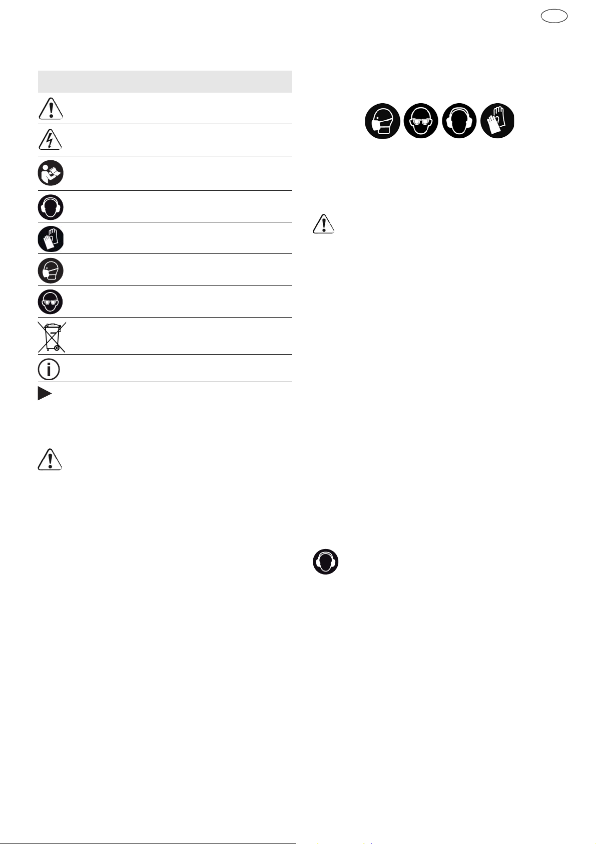
Originální návod k použití
1Symboly
Symbol Význam
Varování před všeobecným nebezpečím
Varování před úrazem elektrickým proudem
Přečtěte si návod k použití, bezpečnostní
pokyny!
Noste chrániče sluchu!
Noste ochranné rukavice!
Používejte respirátor!
Noste ochranné brýle!
Nevyhazujte do domovního odpadu.
Rada, upozornění
Instruktážní návod
2 Bezpečnostní pokyny
2.1 Všeobecné bezpečnostní pokyny
Výstraha!
pokyny a instrukce.
varovných upozornění a instrukcí může způsobit zásah elektrickým proudem, požár a/nebo
vážné zranění.
Všechny bezpečnostní pokyny a instrukce uschovejte, abyste je mohli použít i v budoucnosti.
Pojem „elektrické nářadí“, používaný
v bezpečnostních pokynech, se vztahuje na síťové
elektrické nářadí (se síťovým kabelem) a na akumulátorové nářadí (bez síťového kabelu).
2.2 Bezpečnostní pokyny specifické pro
dané nářadí
–
Pokud provádíte práce, při kterých může šroub
narazit na skrytá elektrická vedení, držte nářadí pouze za izolované plochy rukojeti.
šroub dostane do kontaktu s vedením pod napětím, mohou se pod napětím ocitnout i kovové části nářadí, což může mít za následek zásah
elektrickým proudem.
–
Používejte vhodné vyhledávací nástroje
k vyhledání skrytých napájecích vedení nebo
kpráci přizvěte zástupce místní rozvodné spo-
Přečtěte si všechny bezpečnostní
Chyba při dodržování
Pokud se
lečnosti.
DWC
Kontakt nástroje s vedením, jež vede
CZ
elektrické napětí, může vést k vzniku požáru
a úrazu elektrickým proudem. Poškození plynového vedení může vést k výbuchu. Narušení vodovodní trubky způsobí věcné škody.
–
Používejte vhodné osobní ochranné pomůcky:
ochranu sluchu, ochranné brýle, respirátor při
činnostech, kdy dochází ke vzniku prachu, pracovní rukavice při opracovávání hrubých materiálů nebo při výměně nástroje.
POZOR! Elektrické nářadí se může zablokovat a způsobit náhlý zpětný ráz!
Okamžitě ho
vypněte!
–
Držte elektrické nářadí pevně v ruce. Při šroubování nastavte správný krouticí moment. Buďte připraveni na silný reakční moment,
který je
způsobený otáčkami elektrického nářadí a může
způsobit poranění.
–
Elektrické nářadí nepoužívejte v dešti nebo ve
vlhkém prostředí.
Vlhkost v elektrickém nářadí
může způsobit zkrat a požár.
– Spínač zap/vyp nezajišťujte v zapnuté poloze!
– Spojením zásobníku a akušroubováku vzniká za-
řízení, pro které platí bezpečnostní předpisy a a
pokyny pro akušroubovák.
2.3 Hodnoty emisí
Hodnoty zjištěné podle normy EN 60745 činí typicky:
Hladina akustického tlaku LPA = 78 dB(A)
Hladina akustického výkonu LWA = 89 dB(A)
Nejistota K = 3 dB
Noste chrániče sluchu!
Hodnota vibrací ah (součet vektorů ve třech směrech) a nepřesnost K zjištěné podle EN 60745:
DWC 18-2500
DWC 18-4500
ah = 2,8 m/s
K = 1,5 m/s
ah = 3,5 m/s
K = 1,5 m/s
2
2
2
2
Uvedené emitované hodnoty (vibrace, hlučnost)
– slouží k porovnání nářadí,
– jsou vhodné také pro předběžné posouzení zatí-
žení vibracemi a hlukem při použití nářadí,
– vztahují se k hlavním druhům použití elektrické-
ho nářadí.
69
Page 70
DWC
CZ
Ke zvýšení může dojít při jiném použití, s jinými nástroji nebo při nedostatečné údržbě. Vezměte
v úvahu čas, kdy nářadí běží na volnoběh a kdy je vypnuté!
3 Účel použití
Montážní šroubovák je určen pro následující práce:
– Sádrokartonové desky na kovové profily (≤
2,25 mm) - Rychlomontážní stavební šrouby s navrtávacím hrotem
– Sádrokartonové desky na dřevě né konstrukce -
Rychlomontážní stavební šrouby s hrubým závitem
DWC 18-2500
– Sádrovláknité desky na kovové a dřevěné kon-
strukce - Rychlomontážní stavební šrouby pro
sádrovláknité desky
– Dřevotřískové desky/OSB pro dřevěné konstruk-
ce - Vruty do Ø 5 mm
DWC 18-4500
– Sádrokartonové desky na kovové profi ly (≤
0,88 mm) - Rychlomontážní stavební šrouby s
jemným závitem
Při použití v rozporu s určeným účelem nese
odpovědnost uživatel; patří sem také nepřetržitý průmyslový provoz.
4Technické údaje
Akušroubovák pro sádrokarton DWC18-2500 DWC18-4500
Napěti motoru 18 V 18 V
Otáčky naprázdno* 0 - 2500 min
Kroutící moment (měkký / tvrdý) 7 / 18 Nm 5 / 14 Nm
Upnutí nástroje ve vřetenu 1/4 ’’ DIN 3126 / ISO 1173 1/4 ’’ DIN 3126 / ISO 1173
Maximální délka šroubovaných šroubů 55 mm 55 mm
-1
0 - 4500 min
-1
Hmotnost (bez akumulátoru) 1,2 kg
Hmotnost s hloubkovým dorazem (bez akumu-
látoru)
Hmotnost se zásobníkem (bez akumulátoru) 1,6 kg
* Údaje ohledně otáček jsou s plně nabitým akumulátorem.
5 Jednotlivé součásti
[1-1]
[1-2]
[1-3]
[1-4]
[1-5]
[1-6]
[1-7]
Některé vyobrazené nebo popsané příslušenství
není součástí dodávky.
Uvedené obrázky se nacházejí na začátku návodu
kpoužití.
Zásobník bitů
Spínač zap/vyp
Přepínač chodu vpravo/vlevo
Přepínač AUTO/MAN
Hloubkový doraz
Bit
Izolované plochy pro uchopení (oblast
vyznačená šedou barvou)
6 Uvedení do provozu
6.1 Výměna akumulátoru
Nasazení akumulátoru [2 A]
Vyjmutí akumulátoru [2 B]
Akumulátor je při dodání ihned připravený
k použití a lze ho kdykoli nabíjet.
7Nastavení
Nebezpečí poranění
Nastavení provádějte pouze při vypnutém elektrickém nářadí!
7.1 Změna směru otáčení [1-3]
• Přepínač doleva = chod vpravo
• Přepínač doprava = chod vlevo
1,3 kg
POZOR
70
Page 71

8 Upnutí nástroje, adaptéry
VAROVÁNÍ
Nebezpečí poranění
Před prováděním veškerých prací na nářadí vždy
z nářadí vyjměte akumulátor!
8.1 Držak bitu
Držák bitu umožňuje rychlou výměnu bitů.
POZOR
Horký a ostrý nástroj
Nebezpečí poranění
Nepoužívejte tupé a poškozené nástroje!
Noste ochranné rukavice.
DWC
b)
Přepínačem
Přepínač
Zapnutí stroje docílíte zatlačením bitu na šroub.
Není nutno zapínat spínač
[1-3]
nastavte pravý chod stroje.
[1-4]
nastavte do polohy AUTO.
[1-2]
! Auto maticky jsou
nastaveny maximální otáčky.
c)
Přepínačem
Pro zapnutí stroje zapněte spínač
Přepínač MAN/AUTO
Spínačem
Pokud je přepínačem
[1-3]
nastavte levý chod stroje.
[1-4]
je v libovolné poloze.
[1-2]
lze plynule regulovat otáčky.
[1-2]
n astaven levý chod,
[1-2]
.
lze šroubovák uvést do chodu pouhým stisknutím spínače – bez dodatečného tlaku na bit.
K vyšroubování šroubů tudíž nemusí být demontován hloubkový doraz.
CZ
Montáž držáku bitu
Přepínač
Držák bitu
ného otvoru vřetena
Do držáku upněte bit
Poté nasaďte na převodovou skříň hloubkový
[1-4]
nastavte do polohy MAN.
[4-2]
nasaďte na doraz do šestihran-
[4-4]
.
[4-3]
.
doraz jak je popsáno v bodě 9.2.
Demontáž držáku bitu
Sejměte hloubkový doraz dle popisu v bodu 9.2.
Držák silou vytáhnětete z otvoru vřetena.
8.2 Výměna bitu
K výměně bitu
[1-5]
.
Hloubkový doraz nasaďte na bit (viz obr
Vzpříčením hloubkového dorazu s bitem a sou-
[1-6]
můžete použít hloubkový doraz
[4b]
časným tažením je možné bit vytáhnout.
Poté nasaďte do držáku nový bit.
9 Práce s nářadím
9.1 Zapnutí/vypnutí [1-2]
Pouhým stisknutím spínače
spuštění stroje –
Po zašroubování na požadovanou hloubku stroj
není vadou stroje
sám vypne!
Zapnutí stroje lze dosáhnout několika způsoby:
a)
Přepínačem
Přepínač
Pro zapnutí stroje zapněte spínač
[1-3]
nastavte pravý chod stroje.
[1-4]
nastavte do polohy MAN.
časně tlačte bitem na šroub.
Spínačem
[1-2]
lze plynule regulovat otáčky.
[1-2]
ned ojde ke
!
[1-2]
a sou-
9.2 Hloubkový doraz
Otáčením hloubkového dorazu lze nastavit hloubku
zašroubování – viz obrázek
[5]
. Přesnost nastavení
je ca ± 0,1 mm.
Otočení doleva šroub se zapouští hlouběji
Otočení doprava šroub se zapouští do menší
hloubky
Po nastavení hloubky usaďte jeden šroub na zkoušku a hloubku dolaďte.
Montáž hloubkového dorazu
Nasaďte hloubkový doraz
skříň
[4-5], dokud slyšitelně nezapadne
[4-1]
na převodovou
.
Demontáž hloubkového dorazu
).
Hloubkový doraz silou stáhněte z převodové
skříně.
9.3 Hloubkový doraz silou stáhněte z převodové skříně
Pomocí svorky
[6-1]
může být šroubovák do časně
upnut na pracovní oděv – lze jej při pevnit pomocí
šroubu
vhodný pro praváky i leváky – viz obr.
Šroubovák je vybaven hákem
[6-2]
na stroj zleva nebo zprava a je tak
[6]
[7-1]
, který slouží k
.
příležitostnému zavěšení stroje. Může být upevněn
na stroj vlevo nebo vpravo, a to pomocí šroubu
– viz obr
[7]
.
[7-2]
9.4 Zásobník šroubů
Zásobník umožňuje pracovat průběžně, bez zbytečných přestávek.
Nasazení zásobníku
Nejprve sejměte hloubkový doraz
bitu
[4-2]
a bit, jak je popsáno v bodě 8.
Přepínač
[1-4]
nastavte do polohy MAN.
[4-1]
, držák
71
Page 72

DWC
CZ
Bit
[8-1]
nasaďte na doraz do šestihranného ot-
voru vřetena.
Poté nasaďte na převodovou skříň zásobník.
Osazení zásobníku musí zapadnout slyšitelně
do výstupků na převodové skříni.
Zásobník lze polohovat po 30°.
Sejmutí zásobníku
Silným tahem opatrně sejměte zásobník z převodové skříně.
Nastavení délky šroubu
Tlakem na tlačítko
hloubkový doraz
[9-1]
lze vysouvat a zasouvat
[9-2]
a tím nastavit požadova-
nou délku šroubů.
Nastavenou délku šroubů odečtěte na bočních stranách dorazu
[9-3]
.
Vložení pásku se šrouby
Pásek se šrouby
[10-3]
protáhněte nejprve
spodním vedením zásobníku, pak vedením saní,
kde šroub zapadne do pracovní polohy.
Lehkým tahem za pásek se ujistěte, že je pásek
bezpečne usazen. Zkontrolujte, zda je první
šroub v ose šroubování – viz obr.
Potřebnou hloubku šroubování si nastavte kolečkem
Otáčením doprava se šrouby usazují hlouběji,
[10-1]
.
[10]
.
otáčení doleva se vysunují. Na ukazateli předvolby
[10-2]
je možné odečíst aktuální polohu
nastavení.
Po nastavení usaďte jeden šroub na zkoušku a kolečkem
[10-1]
hloubku případně dolaďte. Každá
změna nastavení odpovídá posunutí dorazu o ±
0,1 mm.
Doporučujeme šroubovat v automatickém režimu – viz bod 9.1 b).
Vysunutí pásku
Vysunutí pásku se provádí pouhým tahem směrem vzhůru (obr.
[11]
) nebo stiskem transportní páčky a současným tahem pásku směrem dolů (obr.
[11]
).
10 Pokyny pro práci
– Zásobník nesmí být držen v oblasti hloubkového
dorazu!
– Každé dotahování šroubu musí být dokončeno.
Přerušené dotahování nebo uvolnění přítlaku bě-
hem dotahování může vést k neuspokojivé funkci
přístroje.
– Pásky se zásobními šrouby se smí vyměňovat
pouze pokud je stroj vypnutý.
– V žádném případě nepoužívejte zásobník jinak,
než je popsáno v tomto návodě pro používání.
– Používejte pouze originální šroubovací bity.
– Používejte pouze originální páskované šrouby.
– Pásky se šrouby skladujte vždy v originálním ba-
lení.
– Pracujte vždy v pravém úhlu proti upevňované
desce.
10.1 Údržba zásobníku
Zásobník v podstatě nevyžaduje žádnou údržbu. Po
dlouhodobějším používání jej doporučujeme vyčistit
tlakovým vzduchem.
Zásobník je možno mazat v oblasti vedení saní – viz
obrázek
[12b]
.
Před čištěním demontujte zásobník, jak je popsáno
v předešlých bodech.
Před čištěním vyjměte ze zásobníku pásek se šrouby, jak je popsáno v článku 9.4 <Vysunutí pásku>.
Zásobník sejměte ze šroubovákul.
Demontáž saní
Hloubkový doraz
aby aretační tlačítko
ky pro demontáž saní
Stlačte aretační tlačítko
táhněte saně ze zásobníku – viz obr.
Stiskněte tlačítko
hloubkový doraz – viz obr.
[9-2]
zatlačte do skříně tak,
[12-1]
[9-1]
bylo na úrovni znač-
[12-2]
– viz obr.
[12-1]
a současně vy-
a současně uvolněte
[12c]
.
[12a]
[12b]
.
.
Demontáž transportní páčky
Stiskněte tlačítko
– viz obr.
Uvolněné tlačítko
[13a]
portní pákou
ze saní (obr.
Jednotlivé díly vyčistěte, vadné nebo opotřebo-
.
[13-2]
[13c]
[13-1]
a současně jej vysuňte
[13-1]
(obr.
a pružinou
).
[13b]
[13-3]
) s trans-
vyjměte
vané díly vyměňte a smontujte v obráceném sledu.
Při zpětné montáži trasportní páčky do saní
dbejte na správné usazení pružinky tlačítka
[13-3]
v transportní páčce. Nesprávná montáž může způsobit nefunkčnost transportu
pásků.
72
10.2 Akustické výstražné signály
Při následujících provozních stavech zní akustické
výstražné signály a nářadí se vypne:
Page 73
DWC
CZ
Vybitý akumulátor nebo přetížené
nářadí.
– Vyměňte akumulátor.
– Zmírněte zatížení nářadí.
Nářadí je přehřáté.
–Po vychladnutí můžete nářadí
znovu uvést do provozu.
Lithium-iontový akumulátor je
přehřátý nebo vadný.
– Pomocí nabíječky zkontrolujte
funkčnost vychladlého akumulátoru.
11 Údržba a ošetřování
VAROVÁNÍ
Nebezpečí poranění, nebezpečí úrazu elektrickým proudem
Před prováděním veškerých prací údržby
a opravách vždy z nářadí vyjměte akumulátor!
Všechny práce údržby a opravy, které vyžadují
otevření krytu motoru, smí provádět pouze autorizovaný zákaznický servis.
Servis a opravy
smí provádět pouze
výrobce nebo servisní dílny: nejbližší
adresu najdete na:
www.festool.com/service
EKAT
4
Používejte jen originální náhradní díly
Festool! Obj. č. na:
5
3
2
1
www.festool.com/service
Dodržujte následující pokyny:
– Větrací otvory u elektrického nářadí musí být vol-
né a čisté, aby bylo zajištěné chlazení.
– Připojovací kontakty elektrického nářadí, nabí-
ječky a akumulátoru udržujte čisté.
Ohledně údržby, ošetřování, likvidace
a přepravy akumulátoru se řiďte pokyny, kte-
ré jsou přiložené k akumulátoru!
12 Životní prostředí
Přístroj nevyhazujte do domovního
odpadu!
odevzdejte k ekologické recyklaci. Dodržujte platné národní předpisy.
Pouze EU:
Podle Evropské směrnice o odpadních
elektrických a elektronických zařízeních a aplikace
v národním právu se musí vyřazené elektrické nářadí shromažďovat odděleně a musí se ekologicky
recyklovat.
Informace k REACh:
Přístroj, příslušenství a obaly
www.festool.com/reach
73
Page 74

DWC
PL
Oryginalna instrukcja eksploatacji
1Symbole
Symbol Znaczenie
Ostrzeżenie przed ogólnym zagrożeniem
Ostrzeżenie przed porażeniem prądem
Przeczytać instrukcję obsługi i wskazówki
dot. bezpieczeństwa!
Należy nosić ochronę słuchu!
Należy nosić rękawice ochronne!
Należy stosować ochronę dróg oddechowych!
Należy nosić okulary ochronne!
Nie wyrzucać z odpadami z gospodarstwa
domowego.
Zalecenie, wskazówka
Instrukcja postępowania
2 Wskazówki dotyczące bezpieczeń-
stwa
2.1 Ogólne zalecenia bezpieczeństwa
Ostrzeżenie!
zalecenia bezpieczeństwa pracy i instrukcje.
Nieprzestrzeganie ostrzeżeń i instrukcji
może spowodować porażenie elektryczne, pożar
oraz/lub ciężkie obrażenia.
Wszystkie zalecenia odnośnie bezpieczeństwa
pracy i instrukcje należy zachować do wykorzystania w przyszłości.
Używane w zaleceniach bezpieczeństwa pracy pojęcie „Narzędzie elektryczne“ odnosi się do narzędzi elektrycznych zasilanych z sieci (z przewodem
zasilającym) i do narzędzi elektrycznych zasilanych
z akumulatora (bez przewodu zasilającego).
Należy przeczytać wszystkie
–
Użyć odpowiednich wykrywaczy, aby namierzyć
ukryte przewody zasilające lub wezwać miejscowy zakład energetyczny.
Kontakt narzędzia
eksploatacyjnego z przewodem pod napięciem
może spowodować pożar i zwarcie elektryczne.
Uszkodzenie przewodu gazowego może spowodować wybuch. Wdzieranie się w przewód wodny
powoduje szkody rzeczowe.
–
Należy stosować odpowiednie osobiste wyposażenie zabezpieczające:
ochronę słuchu, okulary
ochronne, maskę przeciwpyłową przy pracach
związanych z pyleniem, rękawice ochronne przy
pracach z materiałami szorstkimi oraz przy wymianie narzędzia.
OSTROŻNIE! Urządzenie elektryczne może
się zablokować i spowodować nagły odrzut!
Natychmiast wyłączyć!
–
Trzymaj elektronarzędzie mocno w dłoni. Ustaw
prawidłowy moment obrotowy w przypadku
śrub. Przygotuj się na wysoki moment reakcji,
który powoduje obrót elektronarzędzia i może
doprowadzić do zranienia.
–
Nie używaj elektronarzędzia w deszczu lub w
wilgotnym otoczeniu.
Wilgoć w elektronarzędziu
może doprowadzić do zwarcia.
– Nie blokować wyłącznika na stałe!
– Z połączenia zasobnika i wkrętarki akumulatoro-
wej powstaje urządzenie, którego dotyczą przepisy bezpieczeństwa dla wkrętarek
akumulatorowych.
2.3 Parametry emisji
Wartości określone na podstawie normy EN 60745
wynoszą w typowym przypadku:
Poziom ciśnienia akustycz-
LPA = 78 dB(A)
nego
Poziom mocy akustycznej LWA = 89 dB(A)
Tolerancja błędu K = 3 dB
Należy nosić ochronę słuchu!
2.2 Zalecenia bezpieczeństwa właściwe dla
urządzenia
–
Podczas wykonywania prac, przy których śruba
może zetknąć się z ukrytymi przewodami przewodzącymi prąd, należy chwytać urządzenie
wyłącznie za izolowane powierzchnie uchwytów.
Po zetknięciu śruby z przewodem przewodzącym napięcie metalowe części urządzenia
mogą także znaleźć się pod napięciem i doprowadzić do porażenia prądem.
74
Wartość emisji wibracji a
(suma wektorowa w
h
trzech kierunkach) oraz nieoznaczoność K ustalone
wg normy EN 60745:
DWC 18-2500
ah = 2,8 m/s
K = 1,5 m/s
DWC 18-4500
ah = 3,5 m/s
K = 1,5 m/s
Podane wartości emisji (wibracje, szmery)
2
2
2
2
Page 75

– służą do porównania narzędzi,
– nadają się one również do tymczasowej oceny ob-
ciążenia wibracjami i hałasem podczas użytkowania.
– odnoszą się do głównych zatosowań tego elek-
tronarzędzia.
Wartości te mogą być wyższe w przypadku innych
zastosowań, w przypadku pracy z innym osprzętem
oraz w przypadku niewłaściwej konserwacji.Należy
uwzględnić czas pracy urządzenia na biegu jałowym oraz czas unieruchomienia!
3 Użycie zgodne z przeznaczeniem
Wkrętarka akumulatorowa do płyt gipsowo-kartonowych przeznaczona jest do wykonywania następujących prac:
DWC 18-2500
– Płyty gipsowo-pilśniowe do konstrukcji metalo-
wych i drewnianych - Wkręty samowiercące z
gwintem nacinającym
DWC
– Płyty wiórowe / OSB do konstrukcji drewnianej -
Wkręty do płyt drewnianych i wiórowych do
Ø5mm
DWC 18-4500
– Płyty gipsowo-kartonowe do profili metalowych
(≤ 0,88 mm) - Wkręty samowiercące z gwintem
drobnozwojowym
– Płyty gipsowo-kartonowe do profili metalowych
(≤ 2,25 mm) - Wkręty samowiercące z końcówką
wiercącą
– Płyty gipsowo-kartonowe do konstrukcji drew-
nianych - Wkręty samowiercące z gwintem grubozwojowym
W przypadku eksploatacji niezgodnej z przeznaczeniem odpowiedzialność ponosi użytkownik.; dotyczy to również przemysłowej
pracy ciągłej.
PL
4 Dane techniczne
Wkrętarka akumulatorowa do płyt gipsowokartonowych
Napięcie silnika 18 V 18 V
Obroty bez obciążenia* 0 - 2500 min
Moment obrotowy (miękki / twardy) 7 / 18 Nm 5 / 14 Nm
Uchwyt narzędziowy 1/4 ’’ DIN 3126 / ISO 1173 1/4 ’’ DIN 3126 / ISO 1173
Maksymalna długość śruby 55 mm 55 mm
Ciężar (bez akumulatorem) 1,2 kg
Ciężar z ogranicznikiem głębokości (bez akumu-
latorem)
Ciężar z zasobnikiem (bez akumulatorem) 1,6 kg
* Dane o prędkości obrotowej przy całkowicie naładowanym akumulatorze.
5 Elementy urządzenia
[1-1]
[1-2]
[1-3]
[1-4]
[1-5]
Magazynek końcówek wkrętakowych (bit)
Włącznik/wyłącznik
Przełącznik obrotów w prawo/w lewo
Przełącznik AUTO/MAN
Ogranicznik głębokości
DWC18-2500 DWC18-4500
-1
0 - 4500 min
1,3 kg
-1
6Rozruch
6.1 Wymiana akumulatora
Wkładanie akumulatora [2 A]
Wyjmowanie akumulatora [2 B]
Akumulator jest w momencie dostawy gotowy
do natychmiastowego użytku i można go w każdej chwili naładować.
[1-6]
[1-7]
Przedstawione lub opisane wyposażenie nie wchodzi częściowo w zakres dostawy.
Podane rysunki znajdują się w załączniku instrukcji
obsługi.
Bit
Zaizolowane powierzchnie chwytania
(obszar zaznaczony na szaro)
7 Ustawienia
OSTROŻNIE
Niebezpieczeństwo zranienia
Wprowadzać ustawienia tylko przy wyłączonym
narzędziu elektrycznym!
75
Page 76

DWC
PL
7.1 Zmiana kierunku obrotów [1-3]
• Przełącznik w lewo = obroty w prawo
• Przełącznik w prawo = obroty w lewo
Po wkręceniu wkrętu na żądaną głębokość
urządzenie samo się wyłączy!
Urządzenie można włączyć kilkoma sposobami:
8 Uchwyt narzędziowy, przystawki
OSTRZEŻENIE
Ryzyko urazu
Przed przystąpieniem do wykonywania jakichkolwiek prac przy urządzeniu należy wyjąć z niej
akumulator!
8.1 Uchwyt bitów
Uchwyt bitów umożliwia szybką wymianę bitów.
OSTROŻNIE
Gorące i ostre narzędzia
Niebezpieczeństwo zranienia
Nie używaj tępych lub uszkodzonych narzędzi!
Nosić rękawice ochronne.
Montaż uchwytu bitów
Przełącznik
Uchwyt bitów
narzędziowy
W uchwycie umieścić bit
Następnie umieścić na obudowie przekładni
[1-4]
ustawić w pozycji MAN.
[4-2]
wsunąć do oporu w uchwyt
[4-4]
.
[4-3]
.
ogranicznik głębokości w sposób opisany w
punkcie 9.2.
Demontaż uchwytu bitów
Zdjąć ogranicznik głębokości według opisu w
punkcie 9.2.
Silnym pociągnięciem wyjąć uchwyt bitów z
uchwytu narzędziowego.
8.2 Wymiana bitów
Do wymiany bitów
głębokości
Ogranicznik głębokości nałożyć na bit (patrz rys.
[4b]
Po zakleszczeniu ogranicznika głębokości na
[1-5]
).
.
[1-6]
można użyć ogranicznika
bicie można wyciągnąć bit.
Następnie włożyć nowy bit w uchwyt bitów.
9 Praca za pomocą urządzenia
9.1 Włączanie/wyłączanie [1-2]
Po naciśnięciu samego włącznika
stąpi włączenie urządzenia –
urządzenia
!
[1-2]
nie na-
nie jest to wada
a)
Przełącznikiem
[1-3]
ustawić prawe obroty na-
rzędzia.
Przełącznik
Aby włączyć urządzenie, należy wcisnąć włącznik
[1-2]
[1-4]
ustawić w pozycji MAN.
, dociskając jednocześnie bit do wkrę-
tu.
Włącznikiem
[1-2]
można płynnie regulować obro-
ty.
b)
Przełącznikiem
[1-3]
ustawić prawe obroty na-
rzędzia.
Przełącznik
[1-4]
ustawić w pozycji AUTO, urzą-
dzenie włączy się po naciśnięciu bitem na wkręt.
Nie jest konieczne wciskanie włącznika
[1-2]
! Automatycznie ustawione zostaną maksymalne obroty.
c)
Przełącznikiem
[1-3]
ustawić lewe obroty na-
rzędzia.
Włączyć urządzenie za pomocą włącznika
Przełącznik MAN/AUTO
[1-4]
jest w dowolnej
[1-2]
pozycji.
Naciskając na włącznik
[1-2]
można płynnie regu-
lować obroty.
Jeżeli urządzenie ustawione jest lewe obroty,
wówczas można uruchomić wkrętarkę naci-
[1-2]
śnięciem na sam włącznik
– bez dodatko-
wego nacisku na bit.
W celu wykręcenia wkrętu nie trzeba demontować ogranicznika głębokości.
9.2 Ogranicznik głębokości
Obracając ogranicznik głębokości można ustawiać
głębokość wkręcania – patrz rysunekd
[5]
. Dokład-
ność nastawy wynosi ok. ± 0,1 mm.
Po obróceniu w
wkręt wkręcany jest głębiej.
lewo
Po obróceniu w
prawo
wkręt wkręcany jest na mniejszą głębokość
Po ustawieniu głębokości należy wkręcić jeden
wkręt na próbę i w razie potrzeby skorygować głębokość.
Montaż ogranicznika głębokości
Nałożyć ogranicznik głębokości
wę przekładni
[4-5]
.
[4-1]
na obudo-
.
76
Page 77

Następnie docisnąć ogranicznik głębokości tak,
aby zablokował się w zatrzasku z wyraźnym
dźwiękiem.
Demontaż ogranicznika głębokości
Zdjąć ogranicznik głębokości z obudowy przekładni.
9.3 Hak do zawieszenia i uchwyt na pasek
Za pomocą uchwytu na pasek
[6-1]
wkrętarkę można tymczasowo zamocować na odzieży roboczej –
można go zamontować z pomocą śruby
[6-2]
na
urządzeniu po lewej lub prawej stronie, dzięki czemu nadaje się on zarówno dla osób lewo- i praworęcznych – patrz rys.
Wkrętarka posiada hak
[6]
.
[7-1]
, który służy w razie
potrzeby do zawieszenia urządzenia. Można go zamontować na urządzeniu po lewej lub prawej stronie za pomocą śruby
[7-2]
– patrz rys.
[7]
.
9.4 Zasobnik wkrętów
Zasobnik umożliwia pracę ciągłą bez zbędnych
przerw.
Wkładanie zasobnika
Najpierw należy zdjąć ogranicznik głębokości
[4-1]
i uchwyt bitów
[4-2]
wraz z bitem, w spo-
sób opisany w punkcie 8.
Przełącznik
Długi bit
rzędziowy
Następnie umieścić zasobnik na obudowie
[1-4]
ustawić w pozycji MAN.
[8-1]
wsunąć do oporu w uchwyt na-
[4-4]
tak, aby się zablokował.
przekładni. Zasobnik musi zablokować się w zatrzasu z wyraźny dźwiękiem.
Zasobnik można obracać w skokach co 30°.
Zdejmowanie zasobnika
Zdjąć zasobnik z obudowy przekładni silnym pociągnięciem.
Ustawianie długości wkrętów
Naciskając na przycisk
wysuwać ogranicznik głębokości
[9-1]
można wsuwać i
[9-2]
, usta-
wiając w ten sposób żądaną długość wkrętów.
Ustawioną długość wkrętów można odczytać na
bokach ogranicznika głębokości
[9-3]
.
Wkładanie taśmy z wkrętami
Taśmę ze wkrętami
[10-3]
przeciągnąć najpierw przez dolną prowadnicę zasobnika, następnie przez prowadnicę sanek tak, aby wkręt
znalazł się w pozycji roboczej.
Lekko ciągnąc za taśmę upewnić się, że taśma
jest bezpiecznie zamocowana.
Skontrolować, czy pierwszy wkręt znajduje się w
osi wkręcania – patrz rys.
[10]
.
DWC
Ustawić wymaganą głębokość wkręcania za pomocą pokrętła
[10-1]
, po obróceniu w prawo
PL
wkręty wkręcane są głębiej, po obróceniu w
lewo na mniejszą głębokość.
Na wskaźniku wstępnej nastawy
[10-2]
można
odczytać aktualne ustawienie.
Po dokonaniu ustawień wkręcić jeden wkręt na próbę a następnie w razie potrzeby skorygować głębokość za pomocą pokrętła
[10-1]
. Każda zmiana
ustawienia odpowiada przesunięciu ogranicznika o
± 0,1 mm.
Zalecamy wkręcanie w trybie automatycznym –
patrz punkt 9.1 b).
Wyjmowanie taśmy z wkrętami
Wyjmowanie taśmy odbywa się poprzez pociągnięcie jej w górę (rys.
[11]
) Wyjmowanie ta-
śmy odbywa się poprzez pociągnięcie jej w górę
[11]
(rys.
).
10 Zalecenia dotyczące pracy
– Zasobnik nie może być trzymany w strefie ogra-
nicznika głębokości!
– Każda operacja wkręcania musi zostać przepro-
wadzona do końca. Przerwanie wkręcenia lub
zwolnienie nacisku w trakcie wkręcania może
prowadzić do nieprawidłowego funkcjonowania
urządzenia.
– Taśmy z wkrętami można wymieniać wyłącznie
wówczas, gdy urządzenie jest wyłączone.
– W żadnym wypadku nie wolno używać zasobnika
w inny sposób, niż opisany w niniejszej instrukcji
obsługi.
– Używać wyłącznie oryginalnych bitów do wkrę-
tów.
– Używać wyłącznie oryginalnych taśm z wkrętami.
– Taśmy z wkrętami należy przechowywać zawsze
w oryginalnym opakowaniu.
– Pracować zawsze pod kątem prostym w stosun-
ku do mocowanej płyty.
10.1 Konserwacja zasobnika
Zasobnik w zasadzie nie wymaga żadnej konserwacji. Po długotrwałym użytkowaniu zalecamy jego
wyczyszczenie sprężonym powietrzem.
Nakładkę zasobnika można smarować w obszarze
prowadnicy sanek – patrz rys.
Przed przystąpieniem do czyszczenia należy zdemontować zasobnik, w sposób opisany w poprzednich punktach.
Przed przystąpieniem do czyszczenia wyjąć z zasobnika taśmę z wkrętami, w sposób opisany w
punkcie 9.4 <Wyjmowanie taśmy z wkrętami>.
[12b]
.
77
Page 78

DWC
peep
― ―
peep peep
―
peep peep peep
PL
Zdjąć zasobnik z wkrętarki.
Demontaż sanek
Ogranicznik głębokości
wę tak, aby przycisk blokujący
[9-2]
wcisnąć w obudo-
[12-1]
znalazł się
na poziomie oznaczenia do demontażu sanek
[12-2]
Nacisnąć przycisk blokady
– patrz rys.
[12a]
.
[12-1]
, wyciągając
jednocześnie sanki z zasobnika – patrz rys.
[12b]
.
Nacisnąć przycisk
śnie ogranicznik głębokości – patrz rys.
[9-1]
, zwalniając jednocze-
[12c]
.
Demontaż dźwigni transportowej
Nacisnąć przycisk
nocześnie w kierunku strzałki – patrz rys.
Zwolniony przycisk
gnią transportową
jąć z sanek (rys.
Poszczególne części wyczyścić, wadliwe lub zu-
[13-1]
[13-1]
[13-2]
[13c]
, przesuwając go jed-
(rys.
i sprężyną
[13b]
[13-3]
) z dźwi-
).
[13a]
wy-
żyte części wymienić i zmontować w odwrotnej
kolejności.
Podczas ponownego montażu dźwigni transportowej należy zadbać o prawidłowe osadzenie sprężynki przycisku
[13-3]
w dźwigni
transportowej. Nieprawidłowy montaż może
spowodować niesprawność transportu taśm.
10.2 Akustyczne sygnały ostrzegawcze
Akustyczne sygnały ostrzegawcze rozlegają się
przy następujących stanach pracy urządzenia po
czym następuje wyłączenie urządzenia:
Rozładowanie akumulatora lub
przeciążenie urządzenia.
– Wymienić akumulator.
– Zmniejszyć obciążenie urządze-
nia.
11 Konserwacja i utrzymanie w czy-
stości
OSTRZEŻENIE
Niebezpieczeństwo zranienia, porażenie prądem
Przed przystąpieniem do wykonywania jakichkolwiek prac konserwacyjnych i czyszczenia zawsze należy wyjmować z niego akumulator!
Wszelkie prace konserwacyjne i naprawcze, które wymagają otwarcia obudowy silnika, mogą
być wykonywane wyłącznie przez autoryzowany
warsztat serwisowy.
.
EKAT
2
1
Przestrzegać poniższych zaleceń:
– Otwory wentylacyjne w elektronarzędziu nie
mogą być zakrywane i powinny być utrzymywane
w czystości, aby zapewnić chłodzenie.
– Utrzymywać w czystości styki przyłączy elektro-
narzędzia, ładowarki oraz akumulatora.
Należy przestrzegać dołączonych do akumu-
latora wskazówek dotyczących konserwacji i
utrzymania we właściwym stanie, złomowania i
transportu akumulatora!
Obsługa serwisowa i naprawy
nie u producenta lub w warsztatach
autoryzowanych: prosimy wybrać najbliższe miejsce spośród adresów zamieszczonych na stronie:
www.festool.com/service
4
Należy stosować wyłącznie oryginalne
części zamienne firmy Festool.Nr za-
5
3
mówienia pod:
www.festool.com/service
wyłącz-
78
Urządzenie jest przegrzane.
– Po ostygnięciu można ponownie
uruchomić urządzenie.
Przegrzanie lub uszkodzenie akumulatora LiIon.
– Sprawdzić funkcjonowanie ostu-
dzonego akumulatora za pomocą
ładowarki.
12 Środowisko
Nie wyrzucać urządzenia razem z odpadami domowymi!
posażenie dodatkowe oraz opakowania należy przeznaczyć do odzysku
zgodnie z przepisami o ochronie środowiska. Przestrzegać obowiązujących przepisów krajowych.
Wyłącznie UE:
Zgodnie z wytyczną europejską o zużytych urządzeniach elektrycznych i elektronicznych
oraz jej adaptacją do prawa krajowego zużyte narzędzia elektryczne muszą być gromadzone osobno i
odprowadzane do odzysku surowców wtórnych
zgodnego z przepisami o ochronie środowiska.
Informacje dotyczące rozporządzenia REACH:
www.festool.com/reach
Urządzenia, wy-
 Loading...