

Page 1

Originalbetriebsanleitung 6
Original operating manual 13
Notice d’utilisation d’origine 20
Manual de instrucciones original 27
Istruzioni per l’uso originali 34
Originele gebruiksaanwijzing 41
Originalbruksanvisning 48
Alkuperäiset käyttöohjeet 54
Original brugsanvisning 60
Originalbruksanvisning 66
Manual de instruções original 72
Оригинал Руководства по эксплуатации 79
Originální návod k použití 87
Oryginalna instrukcja eksploatacji 93
D U R A D R I V E
DWC 18-2500
DWC 18-4500
767889_002
Page 2
1-5
1-4
1-3
1
1-6
1-2
1-1
2A 2B
klick
2
1
Page 3
3
3 a
120 mm
4 a
4-1
4-2
4-5
3-1
3-2
Ø 5 mm
4 mm
4 b
5
4-3
4-4
6
6-1
6-2
Page 4
7
8
7-2
7-1
8-1
9
9-1
9-2
10 11
10-1
9-3
10-3
10-2
Page 5
12 a
12 b
12-2
12-1
13 a
13 b
13-1
12 c
13 c
13-3
13-2
Page 6
Originalbetriebsanleitung D
1 Sicherheitshinweise
1.1 Allgemeine Sicherheitshinweise
WARNUNG! Lesen Sie sämtliche Sicherheitshinweise und Anweisungen.
Fehler bei der Einhaltung der Warnhinweise und Anweisungen können elek-
trischen Schlag, Brand und/oder schwere Verletzungen verursachen.
Bewahren Sie alle Sicherheitshinweise und Anweisungen für die Zukunft auf.
Der in den Sicherheitshinweisen verwendete Begriff „Elektrowerkzeug“ bezieht
sich auf netzbetriebene Elektrowerkzeuge (mit Netzkabel) und auf akkubetriebene
Elektrowerkzeuge (ohne Netzkabel).
1.2 Maschinenspezifi sche Sicherheitshinweise
- Halten Sie das Gerät nur an den isolierten Griffflächen, wenn Sie Arbeiten
ausführen, bei denen die Schraube verborgene Stromleitungen treffen kann.
Der Kontakt der Schraube mit einer spannungsführenden Leitung kann auch
metallene Geräteteile unter Spannung setzen und zu einem elektrischen Schlag
führen.
- Dieses Ladegerät kann von Kindern ab 8 Jahren und darüber sowie von Per-
sonen mit verringerten physischen, sensorischen oder mentalen Fähigkeiten
oder Mangel an Erfahrung und Wissen benutzt werden, wenn sie beaufsichtigt
werden oder bezüglich des sicheren Gebrauchs des Gerätes unterwiesen wurden und die daraus resultierenden Gefahren verstehen. Kinder dürfen nicht mit
dem Gerät spielen. Reinigung und Benutzerwartung dürfen nicht von Kindern
ohne Beaufsichtigung durchgeführt werden.
Tragen Sie geeignete persönliche Schutzausrüstungen:
Gehörschutz, Schutzbrille, Staubmaske bei stauberzeugenden Arbeiten, Schutzhandschuhe beim Bearbeiten
rauer Materialien und beim Werkzeugwechsel.
- Achten Sie beim Schrauben in Wände auf eventuell vorhandene Gas-, Strom-
oder Wasserleitungen.
- Akkupack und Ladegerät nicht öffnen!
- Ladegerät vor Metallteilen (z. B. Metallspäne) oder Flüssigkeiten schützen!
- Keine Fremd-Akkupacks, keine Fremd-Ladegeräte verwenden!
- Akkupack vor Hitze z. B. auch vor dauernder Sonneneinstrahlung und Feuer
schützen!
- Brennende LiIon-Akkupacks nie mit Wasser löschen! Sand oder Feuerlöschde-
cke verwenden.
- Regelmäßig den Stecker und das Kabel prüfen und diese bei Beschädigung von
einer autorisierten Kundendienst-Werkstätte erneuern lassen.
- Durch Verbindung von Magazinvorsatz und Trockenbauschrauber entsteht ein
Gerät, für welches die Sicherheitsvorschriften und -hinweise des Trockenbauschraubers gelten.
6
Page 7
1.3 Emissionswerte
Die nach EN 60 745 ermittelten Werte betra gen
typischerweise:
Schalldruckpegel L
Schallleistungspegel L
= 78 dB (A)
PA
= 89 dB (A)
WA
Messunsicherheitszuschlag K = 3 dB
– repräsentieren die hauptsächlichen Anwendun-
gen des Elektrowerkzeugs.
Erhöhung möglich bei anderen Anwendungen,
mit anderen Einsatzwerkzeugen oder ungenügend gewartet. Leerlauf- und Stillstandszeiten
der Maschine beachten!
2 Symbole
Der beim Arbeiten entstehende Schall kann
das Gehör schädigen.
Gehörschutz tragen!
Schwingungsgesamtwerte (Vektorsumme dreier
Richtungen) ermittelt entsprechend EN 60 745:
DWC 18-2500
Schwingungsemissionswert
(3-achsig) a
Unsicherheit K = 1,5 m/s
DWC 18-4500
Schwingungsemissionswert
(3-achsig) ah = 3,5 m/s
Unsicherheit K = 1,5 m/s
Die angegebenen Emissionswerte (Vibration, Geräusch)
– dienen dem Maschinenvergleich,
– eignen sich auch für eine vorläufi ge Einschät-
zung der Vibrations- und Geräuschbelastung
beim Einsatz,
VORSICHT
= 2,8 m/s
h
Warnung vor allgemeiner Gefahr
Gefahr vor Stromschlag
Anleitung/Hinweise lesen!
Staubmaske tragen!
2
2
Gehörschutz tragen!
2
2
Augenschutz tragen!
Schutzhandschuhe tragen!
Nicht in Hausmüll werfen!
Hinweis, Tipp
3 Technische Daten
Akku-Trockenbauschrauber DWC 18-2500 DWC 18-4500
Motorspannung 18 V 18 V
Leerlaufdrehzahl* 0 – 2500/min 0 – 4500/min
Drehmoment (weich / hart) 7 / 18 Nm 5 / 14 Nm
Werkzeugaufnahme ¼“ DIN 3126 / ISO 1173
Gewicht (ohne Akkupack) 1,1 kg 1,1 kg
Gewicht mit Tiefenanschlag (ohne Akkupack) 1,2 kg 1,2 kg
Gewicht mit Magazinvorsatz (ohne Akkupack) 1,5 kg 1,5 kg
Ladegerät TCL 3
Netzspannung (Eingang) 220 - 240 V ~
Netzfrequenz 50/60 Hz
Ladespannung (Ausgang) 10,8 - 18 V=
Schnellladung max. 3 A
Erhaltungsladung pulsierend
(NiCd, NiMH) ca. 0,06 A
Ladezeiten für BP, BPS und BPC-Akkupacks
LiIon 1,5 Ah, 80 %/100 % ca. 25/35 min.
LiIon 3,0 Ah, 80 %/100 % ca. 55/70 min.
LiIon 4,2 Ah, 80 %/100 % ca. 70/90 min.
Zulässiger Betriebstemperaturbereich
-5 °C bis + 45 °C
Temperaturüberwachung mittels NTC Widerstand
Schutzklasse
/ II
Akkupacks BPC 18 Li
Spannung 18 V
Kapazität 4,2 Ah
Gewicht 0,7 kg
* Drehzahl-Angaben mit voll geladenem Akkupack.
7
Page 8
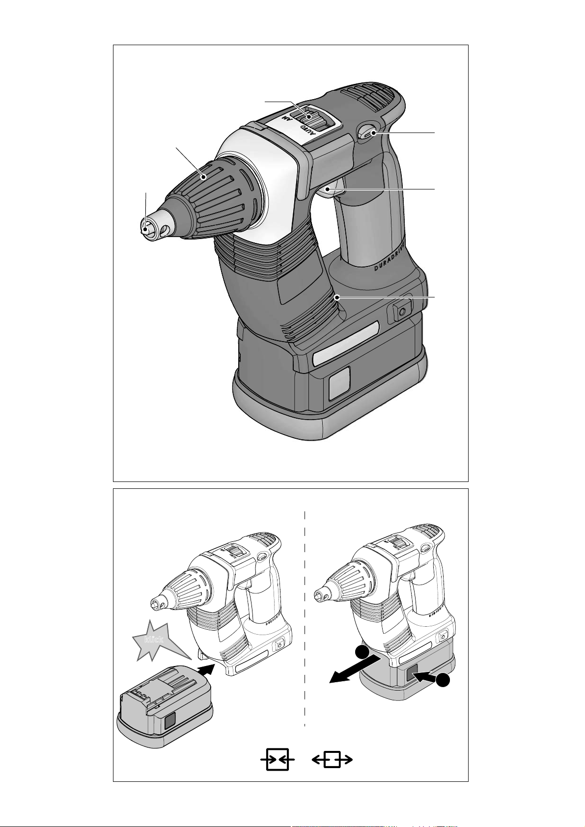
4 Geräteelemente
[1-1] Bit-Depot
[1-2] Ein-/Ausschalter
[1-3] Rechts-/Links-Schalter
[1-4] Umschalter AUTO/MAN
[1-5] Tiefenanschlag
[1-6] Bit
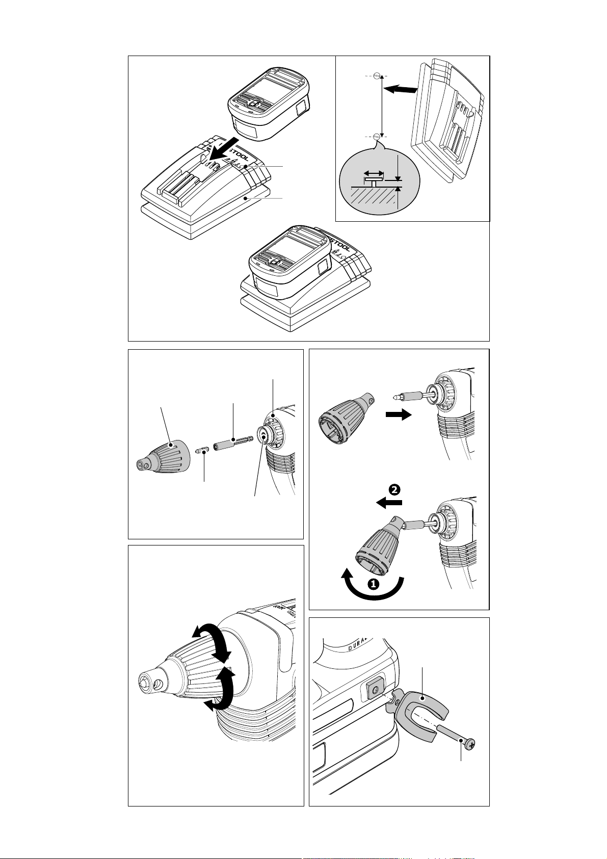
[3-1] LED
[3-2] Kabelaufwicklung
[3a] Wandbefestigung Ladegerät
Abgebildetes oder beschriebenes Zubehör gehört
teilweise nicht zum Lieferumfang.
Die angegebenen Abbildungen befi nden sich am
Anfang der Betriebsanleitung.
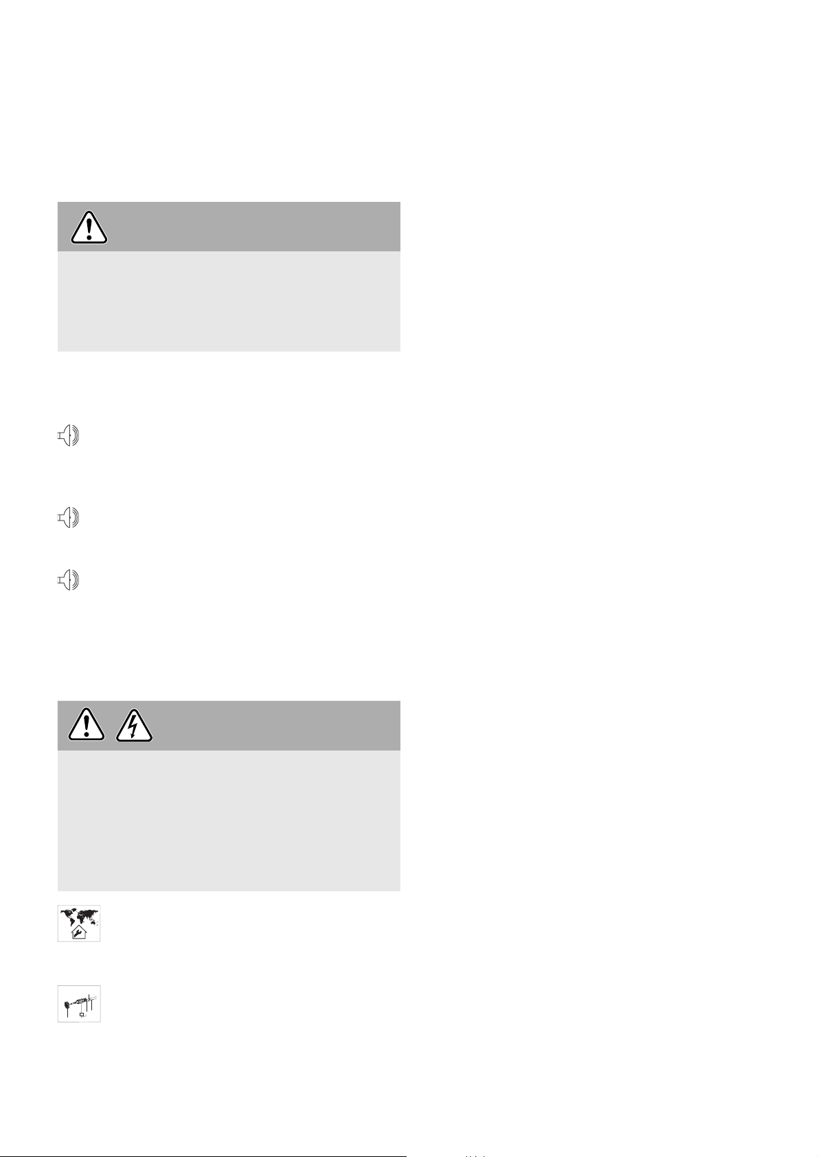
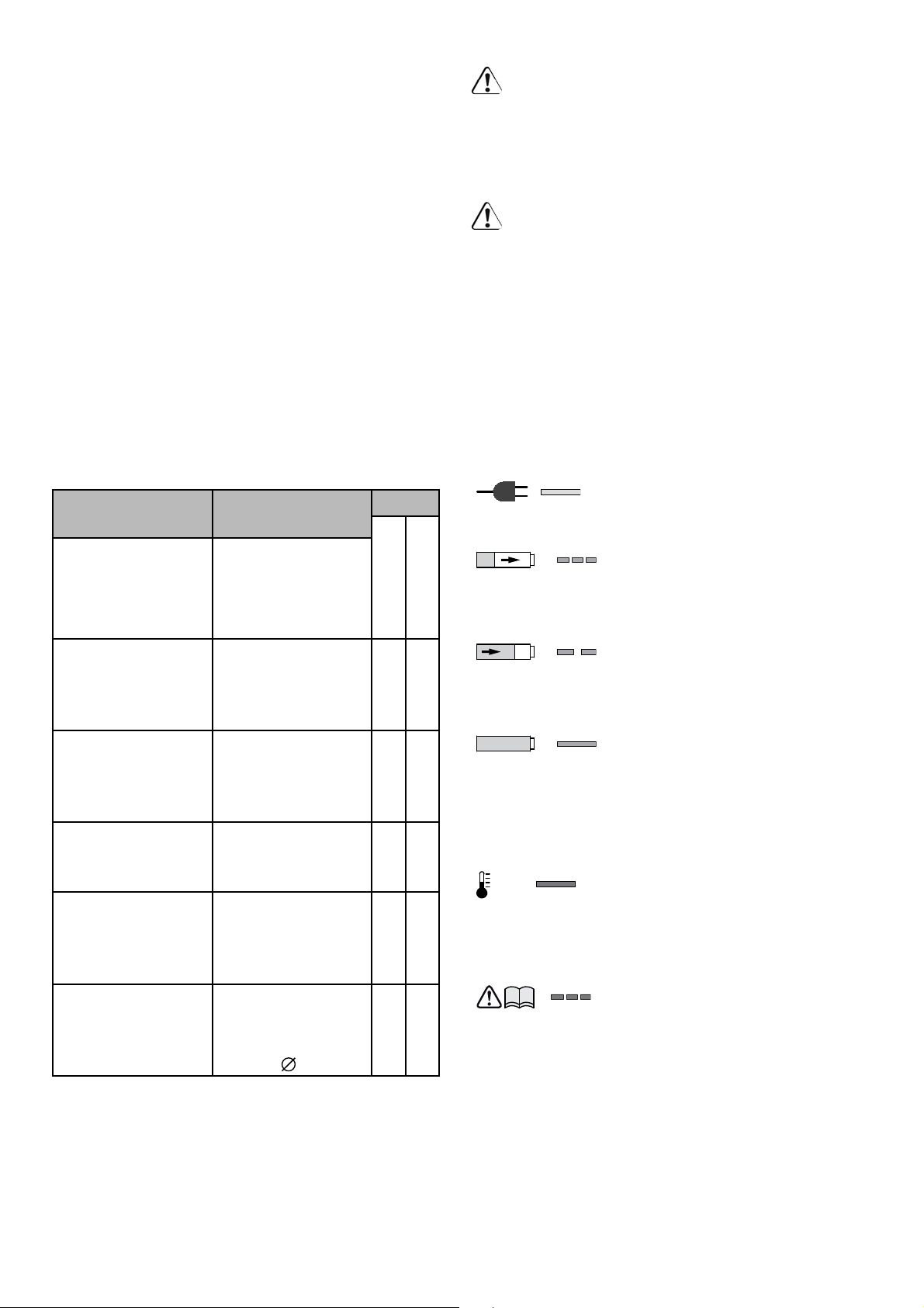
5 Bestimmungsgemäße Verwendung
Der Trockenbauschrauber ist für folgende Schraubarbeiten bestimmt:
Hauptanwendung Schraubentypen Typ
DWC 18-2500
DWC 18-4500
Gipskartonplatten auf Metallprofi lschienen
(≤ 0,88 mm)
Gipskartonplatten auf Metallprofi lschienen
(≤ 2,25 mm)
Gipskartonplatten
auf Holzkonstruktionen
Gipsfaserplatten
auf Metall- und
Holzkonstruktionen
Spanplatten/OSB
auf Holzkonstruktion
Ladegerät TCL 3 geeignet
- zum Aufl aden der Festool Akkupacks: BP, BPS
und BPC (NiMH, NiCd, LiIon werden automatisch erkannt.)
- nur für Innengebrauch
Bei nicht bestimmungsgemäßem Gebrauch
haftet der Benutzer; dazu zählt auch industrieller Dauerbetrieb.
8
Schnellbauschrauben mit
Feingewinde
Schnellbauschrauben mit
Bohrspitze
Schnellbauschrauben mit
Grobgewinde
Schnellbauschrauben mit
Fräsrippen
Holzbau- und
Spanplattenschrauben bis
5 mm
×
×
×
×
×
6 Inbetriebnahme
6.1 Kabelaufwicklung Ladegerät [3-2]
Vor Inbetriebnahme muss das Kabel vollständig von der Aussparung abgewickelt
werden.
6.2 Akkupack wechseln
Akkupack einsetzen [2 A]
Akkupack abnehmen [2 B]
Akkupack ist bei Lieferung sofort einsatzbereit
und kann jederzeit aufgeladen werden.
6.3 Akkupack laden [3]
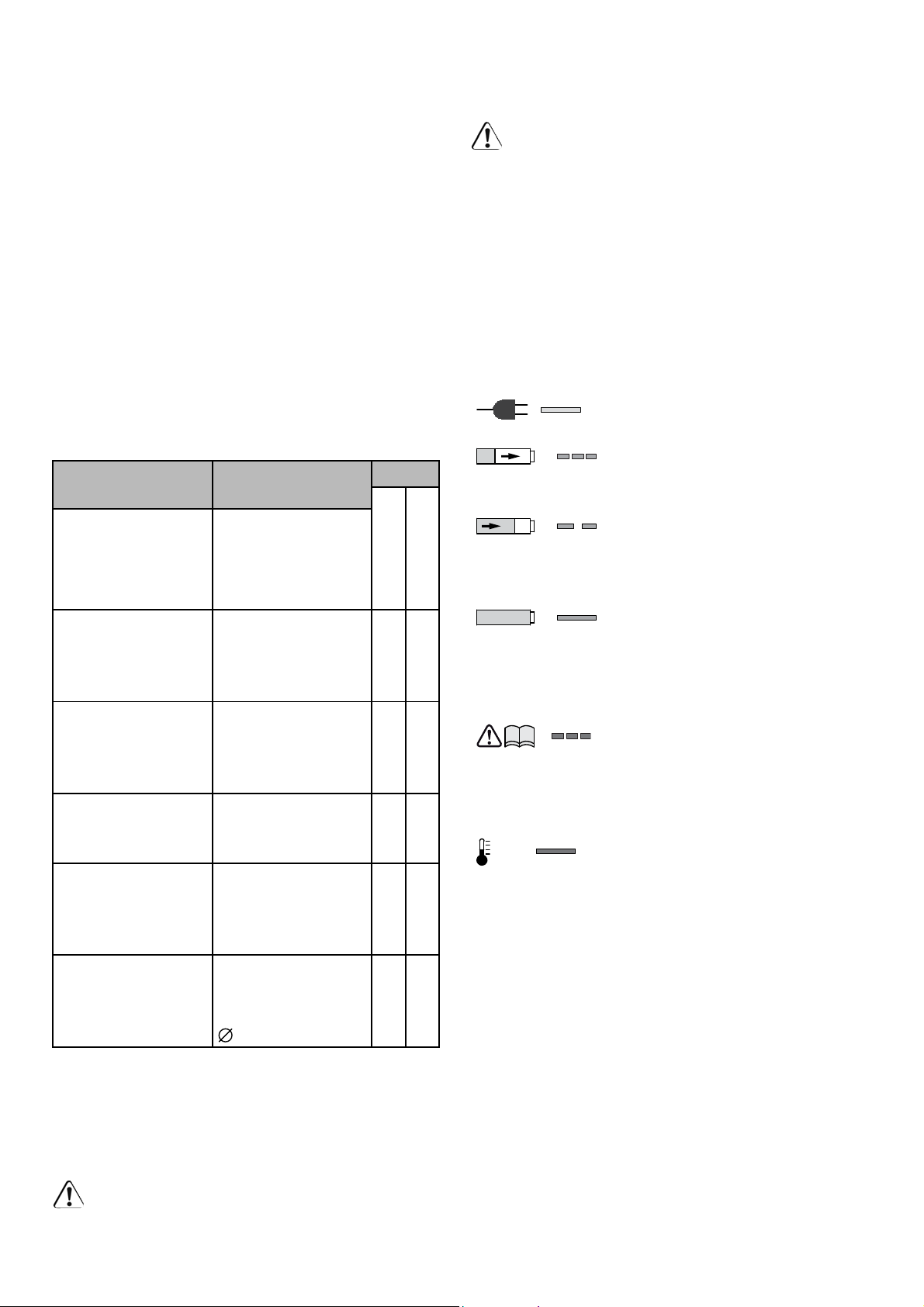
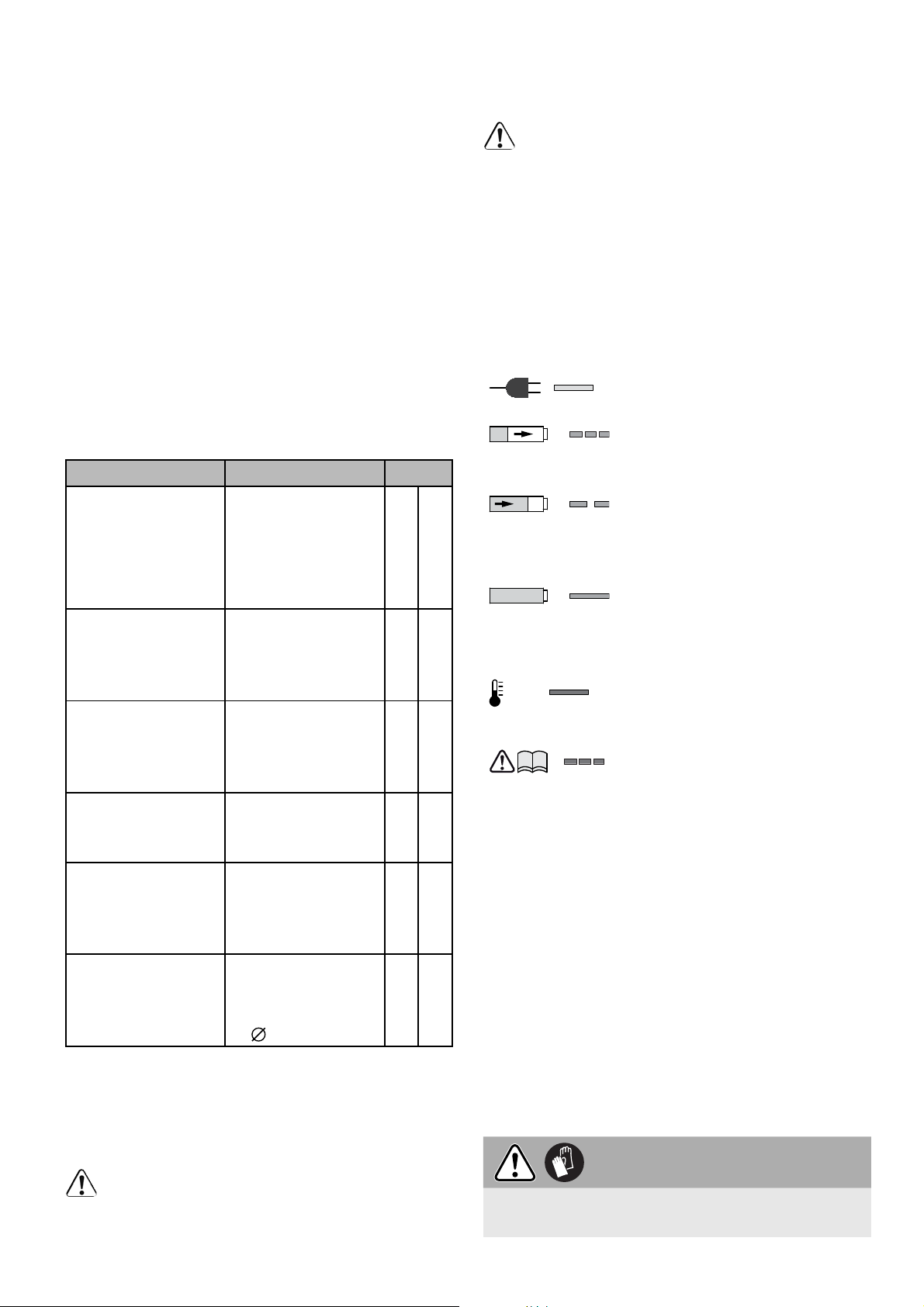
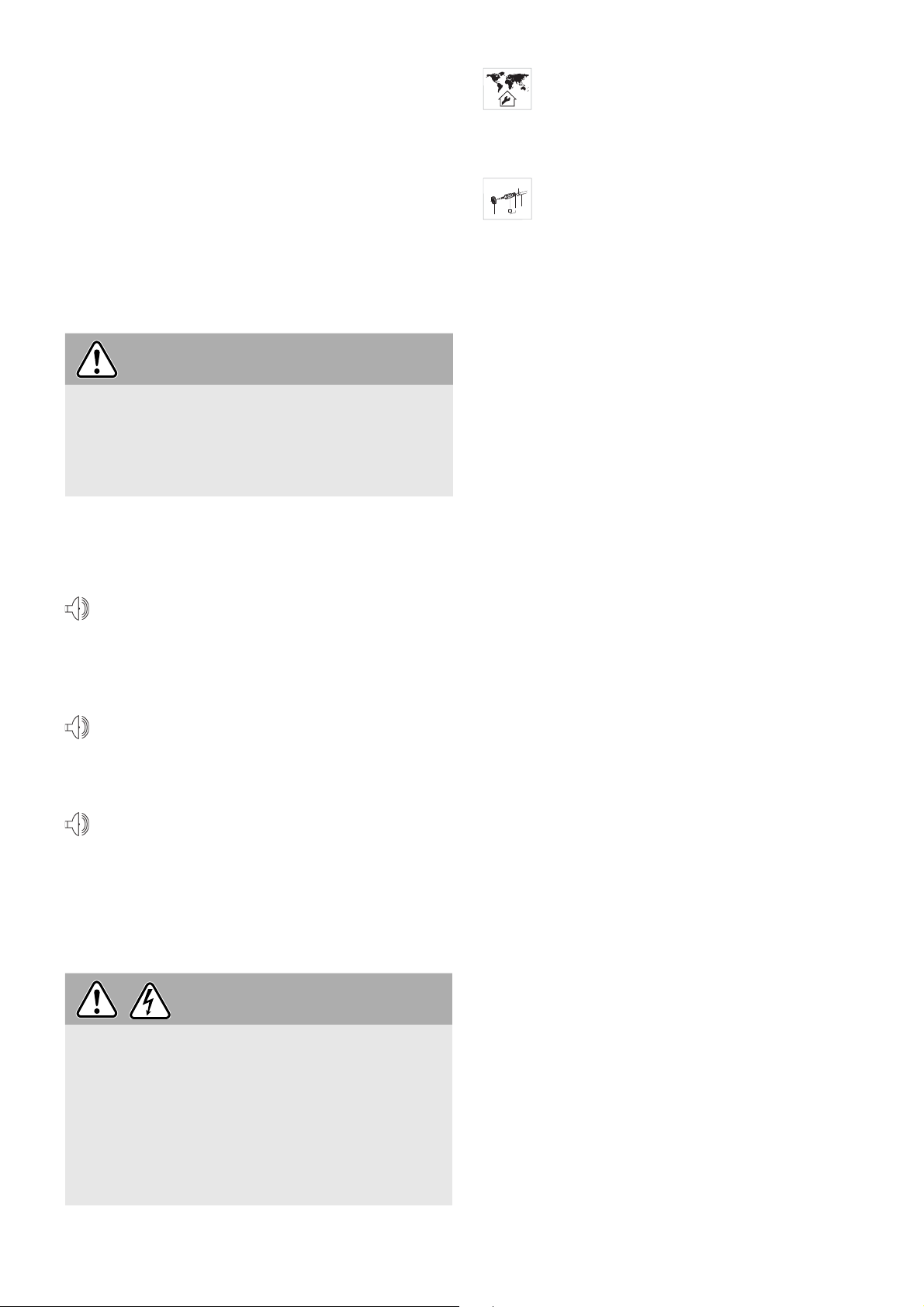
Die LED [3-1] des Ladegeräts zeigt den jeweiligen
Betriebszustand des Ladegerätes an.
LED gelb - Dauerlicht
Ladegerät ist betriebsbereit.
LED grün - schnelles Blinken
Akkupack wird mit maximalem
Strom geladen.
LED grün - langsames Blinken
Akkupack wird mit reduziertem
Strom geladen, LiIon ist zu 80
% geladen.
LED grün - Dauerlicht
Ladevorgang ist beendet oder
wird nicht neu gestartet, da
aktueller Ladezustand größer
80 %.
LED rot - Blinken
Allgemeine Fehleranzeige,
z. B. keine vollständige
Kontaktierung, Kurzschluss,
Akkupack defekt, usw.
LED rot - Dauerlicht
Akkutemperatur ist außerhalb
der zulässigen Grenzwerte.
7 Einstellungen an der Maschine
Einstellungen sollten nur im Stillstand erfol-
gen und werden nur nach einem Neu start registriert.
7.1 Drehrichtung umschalten [1-3]
Schalter von rechts nach links = Rechtslauf;
Schalter von links nach rechts = Linkslauf.
8 Werkzeugwechsel
8.1 Bithalter
Der Bithalter ermöglicht das rasche Auswechseln
der Bits.
Page 9

Beim Auswechseln droht Verletzungsgefahr
durch die scharfen Schneiden.
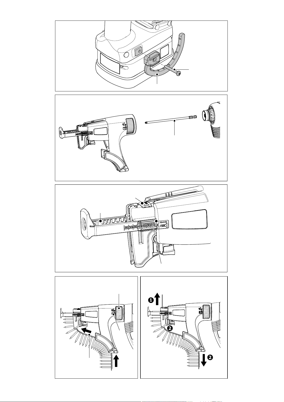
Bithalter montieren
Bithalter demontieren
8.2 Bit wechseln
Zum Wechseln des Bits [1-6] können Sie den Tiefenanschlag [1-5] benutzen.
Schutzhandschuhe tragen!
Schalter [1-4] in Position MAN stellen.
Den Bithalter [4-2] in die Werkzeugaufnahme
[4-4] einstecken bis er einrastet.
Bit [4-3] im Halter einsetzen.
Danach den Tiefenanschlag am Getriebege-
häuse anbringen wie in Kapitel 9.2 beschrie-
ben.
Den Tiefenanschlag wie in Kapitel 9.2 beschrie-
ben abnehmen.
Den Bithalter durch kräftiges Ziehen aus der
Werkzeugaufnahme entnehmen.
Hierfür den Tiefenanschlag wie in Bild [4 b] ge-
zeigt auf den Bit aufsetzen.
Durch Verkanten des Tiefenanschlags mit dem
Bit und gleichzeitigem Ziehen kann der Bit ab-
gezogen werden.
Danach neuen Bit in den Bithalter einsetzen.
VORSICHT
die Schraube drücken.
Es ist kein Drücken des Schalters [1-2] notwendig! Die Höchstdrehzahl ist automatisch eingestellt.
c)
Mittels Rechts-/Links-Schalter [1-3] den
Linkslauf des Gerätes einstellen.
Gerät mittels Schalter [1-2] einschalten.
Der Umschalter MAN/AUTO [1-4] ist in belie-
biger Position.
Durch Druck auf den Schalter [1-2] kann die
Drehzahl stufenlos verändert werden.
Der Trockenbauschrauber läuft im Linkslauf
allein durch Drücken des Schalters [1-2] ohne
zusätzlichen Druck auf den Bit.
Zum Ausschrauben von Schrauben muss der
Tiefenanschlag deshalb nicht abgenommen
werden.
9.2 Tiefenanschlag
Durch Drehen am Tiefenanschlag [1-5] kann die
Schraubtiefe eingestellt werden, wie in Bild [5]
gezeigt. Die Einstellgenauig keit beträgt ca
± 0,1 mm.
Linksdrehung = Schraube wird tiefer ver-
senkt
Rechtsdrehung = Schraube wird weniger tief
versenkt
Nach der Tiefeneinstellung Probeverschraubung
durchführen, danach die Tiefe ggf. korrigieren.
9 Betrieb
9.1 Ein-/Ausschalten
Das Gerät wird nicht allein durch Drücken des
Schalters [1-2] gestartet – kein Gerätedefekt!
Nach dem Einschrauben auf die gewünschte
Tiefe schaltet das Gerät automatisch ab!
Das Gerät lässt sich auf verschiedene Weise einschalten:
a)
Mittels Rechts-/Links-Schalter [1-3] den
Rechtslauf des Geräts einstellen.
Schalter [1-4] in Position MAN stellen.
Um das Gerät einzuschalten, Schalter [1-2]
betätigen und gleichzeitig mit dem Bit auf die
Schraube drücken.
Mit dem Schalter [1-2] kann die Drehzahl stufenlos verändert werden.
b)
Mittels Rechts-/Links-Schalter [1-3] den
Rechtslauf des Geräts einstellen.
Umschalter [1-4] in Position AUTO stellen.
Um das Gerät einzuschalten, mit dem Bit auf
Tiefenanschlag montieren
Den Tiefenanschlag [4-1] auf das Getriebege-
häuse [4-5] aufsetzen.
Danach mit Druck aufstecken bis der Tiefen-
anschlag hörbar einrastet.
Tiefenanschlag demontieren
Durch kräftiges Ziehen den Tiefenanschlag
vom Getriebegehäuse abnehmen.
9.3 Gerüsthaken und Gürtelclip
Mit dem Gürtelclip [6-1] kann das Gerät vorübergehend an der Arbeitskleidung befestigt werden – er kann links- oder rechts am Gerät mittels
Schraube [6-2] montiert werden und ist somit
für Rechts- und Linkshänder geeignet – siehe
Bild [6].
Das Gerät ist mit einem Haken [7-1] versehen,
der zum gelegentlichen Aufhängen des Gerätes
dient. Er kann links- oder rechts am Gehäuse
mit der Schraube [7-2] montiert werden – siehe
Bild [7].
9
Page 10

9.4 Magazinvorsatz
Mithilfe des Magazinvorsatzes kann fortlaufend,
ohne unnötige Pausen, gearbeitet werden.
Anbringen des Magazinvorsatzes
Wie in Kapitel 8 beschrieben, Tiefenanschlag
[4-1] und Bithalter [4-2] mit Bit abnehmen.
Umschalter [1-4] in Position MAN stellen.
Den langen Bit [8-1] in die Werkzeugaufnahme
[4-4] einstecken, bis er einrastet.
Danach den Magazinvorsatz am Getriebege-
häuse anbringen. Der Magazinvorsatz muss
hörbar einrasten.
Der Magazinvorsatz kann in 30°-Abständen
positioniert werden.
Abnehmen des Magazinvorsatzes
Durch kräftiges Ziehen den Magazinvorsatz
vom Getriebegehäuse abnehmen.
Einstellung der Schraubenlänge
Durch Druck auf die Taste [9-1] kann der Tie-
fenanschlag [9-2] ein- oder ausgerückt wer-
den, wodurch er auf die gewünschte Schrau-
benlänge eingestellt werden kann.
Die eingestellte Schraubenlänge ist an den Seiten
des Tiefenanschlags [9-3] ablesbar.
Einlegen der Schraubengurte
Den Schraubengurt [10-3] zuerst durch die un-
tere Magazinführung ziehen und danach in die
Schlittenführung einfädeln bis die Schraube in
ihrer Arbeitsposition einrastet.
Überzeugen Sie sich durch sanften Zug am
Schraubengurt, dass er korrekt und sicher sitzt.
Kontrollieren Sie, ob die erste Schraube in der
Schraubachse liegt – siehe Bild [10].
Mittels Stellrad [10-1] die erforderliche Ein-
schraubtiefe einstellen.
Durch Rechtsdrehen werden die Schrauben
tiefer versenkt, durch Linksdrehen werden die
Schrauben weniger tief versenkt. An der Vor-
wahlanzeige [10-2] kann die aktuelle Einstel-
lung abgelesen werden.
Nach erfolgter Einstellung Probeverschraubung
durchführen, danach ggf. mittels Stellrad [10-1]
die Tiefeneinstellung korrigieren. Jede Veränderung der Einstellung entspricht einer Verschiebung des Anschlags um ± 0,1 mm.
Wir empfehlen im automatischen Modus zu
schrauben – siehe Kapitel 9.1 b).
Entnahme des Schraubengurts
Die Entnahme des Schraubengurtes erfolgt
durch einfachen Zug nach oben (Bild [11]
oder durch Betätigen des Transporthebels und
)
gleichzeitiges Ziehen am Schraubengurt nach
unten (Bild [11]
).
10 Arbeitshinweise
- Der Magazinvorsatz darf nicht im Bereich des
Tiefenanschlags gehalten werden!
- Jeder Schraubvorgang muss bis zu Ende
ausgeführt werden. Die Unterbrechung des
Schraubvorgangs oder der Druckaus übung
beim Schrauben kann Funktionsstörungen am
Gerät verursachen.
- Die Schraubengurte dürfen nur bei Stillstand
des Geräts ausgewechselt werden.
- Den Magazinvorsatz keinesfalls auf andere, als
in dieser Bedienungsanleitung beschriebenen
Weise verwenden.
- Ausschließlich Original-Schraubbits verwen-
den.
- Ausschließlich Original gegurtete Schrauben
verwenden.
- Die Schraubengurte jeweils immer in der Origi-
nalpackung aufbewahren.
- Immer im rechten Winkel zu der zu befestigen-
den Platte arbeiten.
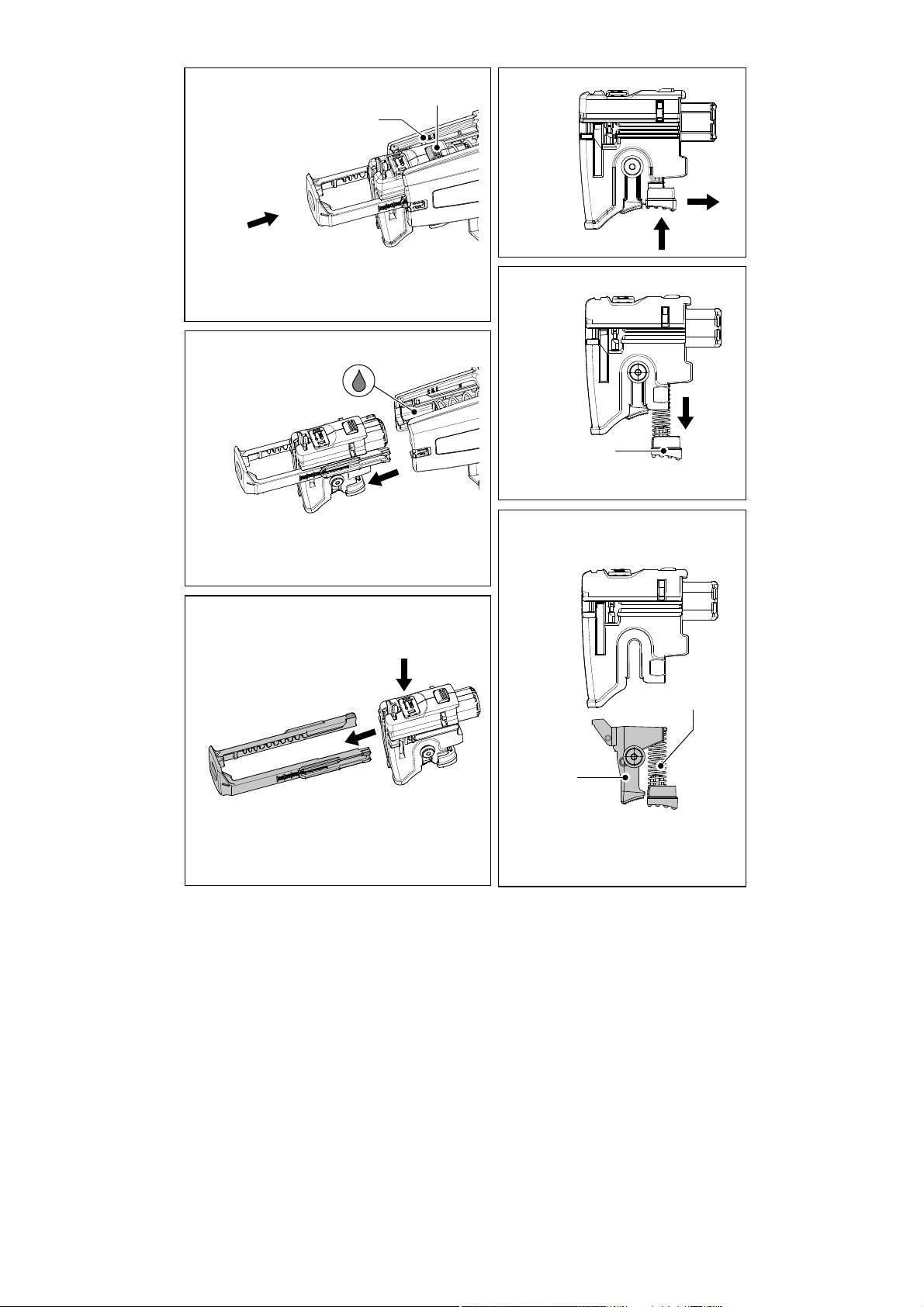
Wartung des Magazinvorsatzes
Der Magazinvorsatz ist im Prinzip wartungsfrei.
Nach längerer Verwendung empfi ehlt es sich, ihn
mit Druckluft zu reinigen.
Der Magazinvorsatz darf im Bereich der Schlittenführung – siehe Bild [12 b] – geschmiert werden.
Zur Reinigung kann der Magazinvorsatz, wie in
den folgenden Punkten beschrieben, zerlegt werden.
Vor der Reinigung den Schraubengurt auf die
im Absatz „Entnahme des Schraubengurts“ beschriebene Weise aus dem Magazin entnehmen.
Den Magazinvorsatz vom Trockenbauschrau ber
abnehmen.
Schlittendemontage
1. Den Tiefenanschlag [9-2] so weit in das Gehäu-
se eindrücken, bis sich die Arretierungstaste
[12-1] auf Höhe der Markierung zur Schlittendemontage [12-2] befi ndet – siehe Bild [12 a].
2. Arretierungstaste [12-1] drücken und gleich-
zeitig den Schlitten aus dem Magazin ziehen
– siehe Bild [12 b].
3. Taste [9-1] drücken und gleichzeitig den Tie-
fenanschlag lösen – siehe Bild [12 c].
Demontage des Transporthebels
1. Taste [13-1] drücken und gleichzeitig in Pfeil-
richtung schieben – siehe Bild [13 a].
10
Page 11
2. Die frei gewordene Taste [13-1] (Bild [13 b])
zusammen mit dem Transporthebel [13-2]
und mit der Feder [13-3] aus dem Schlitten
entnehmen (Bild [13 c]).
Die einzelnen Teile reinigen, defekte oder abgenutzte Teile auswechseln und danach in umgekehrter Reihenfolge montieren.
VORSICHT
Beim Wiedereinbau des Transport hebels in
den Schlitten auf den kor rekten Sitz der Feder
[13-3] im Transporthebel achten. Eine fehlerhafte Montage kann den Schraubengurttransport stören.
Akustische Warnsignale
Akustische Warnsignale ertönen bei folgen den
Betriebszuständen und die Maschine schaltet ab:
- Akku leer oder Maschine
peep
überlastet
• Akku pack wechseln.
• Maschine weniger belasten.
- Maschine ist überhitzt
peep peep
• Maschine nach Abkühlung
wieder in Betrieb nehmen.
- LiIon-Akkupack ist über hitzt
peep peep peep
oder defekt.
• Funk tionsfähigkeit bei
abge kühltem Akkupack mit
dem Ladegerät prüfen.
Folgende Hinweise beachten:
– Die Lüftungsöffnungen am Elektrowerkzeug
frei und sauber halten, damit die Kühlung gewährleistet ist.
– Die Anschlusskontakte am Elektrowerkzeug,
Ladegerät und Akkupack sauber halten.
Hinweise zu Akkupacks
- Lagerung an trockenem, kühlen Ort bei einer
Temperatur von 5 °C bis 25 °C.
– Akkupacks vor Feuchtigkeit und Wasser sowie
vor Hitze schützen.
– Leere Akkupacks nicht länger als ca. einen Mo-
nat im Ladegerät stecken lassen, wenn das
Ladegerät vom Netz getrennt ist. Gefahr der
Tiefentladung!
– Werden LiIon-Akkupacks längere Zeit ohne
Benutzung gelagert, sollten sie mit 40 % Kapazität (ca. 15 min Ladedauer) aufgeladen sein.
– Zur Vermeidung von Kurzschlüssen sollte der
Akkupack in seiner mitgelieferten Verpackung
aufbewahrt werden.
– Eine wesentlich kürzere Betriebszeit je Aufl a-
dung zeigt an, dass der Akkupack verbraucht
ist und durch einen Neuen ersetzt werden muss.
12 Transport
Ein LiIon-Akkupack alleine unterschreitet die einschlägigen Grenzwerte nach UN-Handbuch ST/
SG/AC.10/11/Rev.3 Teil III, Unterabschnitt 38.3.
Beim Transport mehrerer Akkupacks können Gefahrgutvorschriften relevant sein..
11 Wartung und Pfl ege
Unfallgefahr, Stromschlag
Vor allen Arbeiten an der Maschine stets den
Akkupack abnehmen.
Alle Wartungs- und Reparaturarbeiten, die
eine Öffnung des Motorgehäuses erfordern,
dürfen nur von einer autorisierten Kundendienstwerkstatt durchgeführt werden.
Kundendienst und Reparatur nur durch
Hersteller oder durch Servicewerkstätten: Nächstgelegene Adresse unter:
www.festool.com/Service
EKAT
4
Nur original Festool Ersatzteile verwen-
5
3
2
1
den! Bestell-Nr. unter:
www.festool.com/Service
WARNUNG
13 Umwelt
Gerät nicht in den Hausmüll werfen! Geräte, Zu-
behör und Verpackungen einer umweltgerechten
Wiederverwertung zuführen. Geltende nationale
Vorschriften beachten.
Nur EU: Gemäß Europäischer Richtlinie 2002/96/
EG müssen verbrauchte Elektrogeräte getrennt
gesammelt und einer umweltgerechten Wiederverwertung zugeführt werden.
Verbrauchte oder defekte Akkupacks über den
Fachhandel, Festool-Kundendienst oder öffentlich vorgeschriebene Entsorgungseinrichtungen
zurück (geltenden Vorschriften beachten). Akkus
müssen bei Rückgabe entladen sein. Akkupacks
werden so einem geordneten Recycling zugeführt.
Nur EU: Gemäß Europäischer Richtlinie 91/157/
EWG müssen defekte oder verbrauchte Akkupacks/Batterien recycelt werden.
Informationen zur REACh:
www.festool.com/reach
11
Page 12

14 EG-Konformitäts erklärung
Akku-Trockenbauschrauber Serien-Nr.
DWC 18-2500 767850
DWC 18-4500 767898
Jahr der CE-Kennzeichnung: 2013
Wir erklären in alleiniger Verantwortung, dass
dieses Produkt mit allen relevanten Anforderungen folgender Richtlinien, Normen oder normativen Dokumenten übereinstimmt:
2006/42/EG, 2004/108/EG, 2011/65/EU, EN 55 0141, EN 55 014-2, EN 60 745-1, EN 60 745-2-2, EN
61 000-3-2, EN 61 000-3-3.
Ladegerät Serien-Nr.
TCL 3 10002345, 10004911
Jahr der CE-Kennzeichnung: 2013
Wir erklären in alleiniger Verantwortung, dass
dieses Produkt mit allen relevanten Anforderungen folgender Richtlinien, Normen oder normativen Dokumenten übereinstimmt:
2004/108/EG, 2006/95/EG, 2011/65/EU, EN 603351, EN 60335-2-29, EN 61000-3-2, EN 61000-3-3,
EN 61204-3.
Festool Group GmbH & Co. KG
Wertstr. 20, D-73240 Wendlingen
Dr. Martin Zimmer
Leiter Forschung, Entwicklung, technische Dokumentation
2013-04-15
12
Page 13

Original instruction
1 Safety Instructions
GB
1.1 General Safety Instructions
WARNING! Read all safety warnings and all instructions. Failure to follow
the warnings and instructions may result in electric shock, fi re and/or seri-
ous injury.
Save all warnings and instructions for future reference.
The term “power tool” in the warnings refers to your mains-operated (corded)
power tool or battery-operated (cordless) power tool.
1.2 Safety instructions specifi c for the respective tool
- Hold power tool by insulated gripping surfaces, when performing an operation
where the fastener may contact hidden wiring. Fasteners contacting a “live”
wire may make exposed metal parts of the power tool “live” and could give the
operator an electric shock.
- This charger can be used by children of 8 years and upwards and persons with
impaired physical, sensory or mental abilities, or insuffi cient experience or
knowledge, providing they are supervised or have been instructed in the proper
use of the appliance and understand the risks involved. Children are not permitted to play with the appliance. Children must not carry out cleaning tasks
or maintenance unless they are supervised.
Wear suitable protection: such as ear protection, safe-
ty goggles, a dust mask for work which generates dust,
and protective gloves when working with raw materials
and when changing tools.
- Take care when drilling into walls as there is a danger of rupturing concealed
gas/water pipes or cutting through power cables.
- Prevent metal parts (e.g. metal chips) or fl uids from entering the charger!
- Do not use battery packs or chargers from other manufacturers!
- Protect the battery pack from excessive heat or constant heat sources such as
sunlight or naked fl ames!
- Never use water to extinguish burning li-ion battery packs! Use sand or a fi re
blanket.
- Check the plug and the cable regularly and should either become damaged,
have them replaced by an authorised after-sales service workshop.
- Connecting the auto feed attachment and drywall screwdriver results in a device, which is subject to the safety regulations and instruction for the drywall
screw driver.
- Only for AS/NZS: The tool shall always be supplied via residual current device
with a rated residual current of 30 mA or less.
13
Page 14
1.3 Emission levels
Levels determined in accordance with EN 60 745
are typically:
Sound pressure level L
Noise level L
= 78 dB (A)
PA
= 89 dB (A)
WA
Measuring uncertainty allowance K = 3 dB
– They represent the primary applications of the
power tool.
Increase possible for other applications, with other insertion tools or if not maintained adequately.
Take note of idling and downtimes of machine!
2 Symbols
CAUTION
Warning of general danger
The noise produced during work can damage
your hearing.
Risk of electric shock
Always use ear protection.
Overall vibration levels (vector sum for three directions) measured in accordance with EN 60 745:
Read the operating instructions/notes!
DWC 18-2500
Vibration emission level
(3 directions) a
= 2.8 m/s
h
Uncertainty K = 1.5 m/s
2
2
Wear a dust mask!
Wear ear protection!
DWC 18-4500
Vibration emission level
(3 directions) ah = 3.5 m/s
Uncertainty K = 1.5 m/s
The specifi ed emissions values (vibration, noise)
2
2
Wear eye protection!
Wear protective gloves!
– are used to compare machines.
– They are also used for making preliminary es-
Do not throw in the household waste!
timates regarding vibration and noise loads
during operation.
Advice or tip
3 Technical data
Cordless drywall screwdriver DWC 18-2500 DWC 18-4500
Motor voltage 18 V 18 V
Idle speed* 0 – 2500/min 0 – 4500/min
Torque (hard / soft) 7 / 18 Nm 5 / 14 Nm
Chuck ¼” DIN 3126 / ISO 1173
Weight (without battery pack) 1.1 kg 1.1 kg
Weight with depth stopper (without battery pack) 1.2 kg 1.2 kg
Weight with auto feed attachment
(without battery pack) 1.5 kg 1.5 kg
Charger TCL 3
Mains voltage (input) 220 - 240 V ~
Mains frequency 50/60 Hz
Charging voltage (output) 10.8 - 18 V=
Rapid charging max. 3 A
Conservation charging,
intermittent (NiCd, NiMH) approx. 0,06 A
Charging times for BP, BPS and BPC battery packs
Li-ion 1,5 Ah, 80 %/100 % approx. 25/35 min.
Li-ion 3,0 Ah, 80 %/100 % approx. 55/70 min.
Li-ion 4,2 Ah, 80 %/100 % approx. 70/90 min.
Permitted operating temperature range
-5 °C to + 45 °C
14
Temperature monitoring via NTC resistor
Safety class
/ II
Battery pack BPC 18 Li
Voltage 1 18 V
Capacity 4.2 Ah
Weight 0.7 kg
* Speed specifi cations with fully charged battery
pack.
Page 15
4 Machine features
[1-1] Bit storage
[1-2] Switch
[1-3] Forward / reverse switch
[1-4] AUTO/MAN switch
[1-5] Depth stopper
[1-6] Bit
[3-1] LED
[3-2] Cable holder
[3a] Wall mount
The accessories shown or described do not have
to be included with the supplied tool. The specifi ed illustrations appear at the beginning of the
Operating Instructions.
5 Intended use
The drywall screwdriver is designed for the following works:
Main application Screw types Type
DWC 18-2500
DWC 18-4500
Gypsum plaster boards on
metal profi le rails
(≤ 0.88 mm)
Gypsum plaster boards on
metal profi le rails
(≤ 2.25 mm)
Gypsum plaster
boards on wooden
constructions
Gypsum fi bre
boards on metal
and wooden constructions
Chip boards/OSB
on wooden constructions
Drywall screws
with fi ne thread
Drywall screws,
self-drilling
Drywall screws
with coarse
thread
Drywall screws
with milling ribs
Wood construction and chip
board screws up
5 mm
to
×
×
×
×
×
6 Commissioning
6.1 Charger cable holder [3-2]
Unwind the cable completely from the recess before using the charger.
6.2 Changing the battery pack
Removing the battery pack [2 A]
Inserting the battery pack [2 B]
Battery pack is ready for use immediately upon
delivery and can be charged at any time.
6.3 Charging the battery pack [3]
The LED [3-1] on the charger indicates the respective operating status of the charger.
LED yellow – lit continuously
Charger is ready to use.
LED green – fl ashing quickly
Battery pack is charged to maximum capa city.
LED green – fl ashing slowly
Battery pack is charged with reduced current, LiIon is charged
to 80 %.
LED green – lit continuously
Charging is complete or is not
restarted as current charge
status is greater than 80%.
LED red – lit continuously
Battery temperature is outside
the permitted range.
LED red – fl ashing
General fault display, e. g. incomplete contact, short circuit,
battery pack faulty, etc..
7 Power tool settings
Setting must be done only when the power tool
is turned off and will be accepted only after
restarting it.
6.1 Changing the direction of rotation [1-3]
Move switch from right to left = clockwise rotation;
Move switch from left to right = anticlockwise rotation.
Charger TCL 3 suitable for
– charging Festool battery packs: BP, BPS and
BPC (NiMH, NiCd, li-ion are recognised automatically.)
– indoor use only.
The user is liable for improper or non-intended use; this also includes continuous
industrial operation.
8 Tool holder, attachments
8.1 Bit holder
The bit holder is used for fast replacement of bits.
Risk of cutting injuries when changing the tool!
Wear protective gloves!
CAUTION
15
Page 16

Bit holder assembly
Set the switch [1-4] into MAN position.
Set the bit holder [4-2] completely to the hex-
agonal spindle opening [4-4].
Attach bit into the holder [4-3].
Then attach the depth stopper on the gear box
as specifi ed in chapter 9.2.
Bit holder disassembly
Remove the depth stopper as specifi ed in chap-
ter 9.2.
Use power to pull out the holder from the spin-
dle opening.
8.2 Bit replacement
You can use the depth stopper [1-5] for the bit
replacement [1-6].
Attach the depth stopper on the bit (see fi gure
[4 b] ).
By means of jamming the depth stopper with
the bit and concurrent pulling, it is possible to
pull out the bit.
Then attach a new bit in the holder.
9 Operation
9.1 Switching on and off
Pressing only the switch [1-2] does not start
the machine – it is not a machine fault!
Upon screwing to the required depth, the power
tool switches off!
The machine can be switched on by means of several methods:
a)
Set the forward / reverse switch [1-3] into ma-
chine clockwise operation.
Set the switch [1-4] into MAN position. In order
to switch on the power tool, apply the switch [1-
2] and concurrently press the bit on the screw.
Use the switch [1-2] to gradually regulate the
speed.
b)
Set the forward / reverse switch [1-3] into ma-
chine clockwise operation.
Set the switch [1-4] into AUTO position.
Press the bit on the screw and the power tool
will switch on.
Switch [1-2] does not need to be pressed. Maximum speed is set automatically.
c)
Set the forward / reverse switch [1-3] into ma-
chine anti-clockwise operation.
In order to start the power tool, press the
switch [1-2]. The switch MAN/AUTO [1-4] is
in any position.
Use the switch [1-2] to gradually regulate the
speed.
If the forward / reverse switch [1-3] is set to
anti-clockwise operation, the screwdriver can
be started only by pressing the switch [1-2] –
without additional pressure on the bit!
It is not necessary to remove the depth stopper
in order to unscrew screws!
9.2 Depth stopper
Turning the depth stopper sets the screwing depth
– see fi gure [5]. The setting accuracy is approx ±
0.1 mm.
Anti-clockwise rotation = screws are insert-
ed deeper
Clockwise rotation = screws are insert-
ed to lower depth
Upon setting the depth, set some screws to test
and adjust the depth.
Depth stopper assembly
Fit the depth stopper [4-1] on the gear box [4-
5], until it engages in the groove.
Depth stopper disassembly
Remove the depth stopper from the gear box
by pulling it.
9.3 Hook and clip
Use the clip [6-1] to temporarily attach the screwdriver on the working clothing – it can be attached
by means of a screw [6-2] to the left or right of
the power tool, and it is suitable for right and left
handed people – see fi gure [6].
The screwdriver is equipped with a hook [7-1],
which is used for occasional machine suspension.
It can be attached to the left or right of the power
tool, by means of a screw [7-2] – see fi gure [7].
9.4 Auto feed attachment
The auto feed attachment enables to work continuously, without unnecessary delays.
Fitting the auto feed attachment
At fi rst remove the depth stopper [4-1], bit
holder [4-2] and bit, as specifi ed in chapter 8.
Set the switch [1-4] into MAN position.
Push the long bit [8-1] completely to the hex-
agonal spindle opening [4-4].
Then fi t the auto feed attachment on the gear
box.
Push the attachment until it engages in the
groove of the gear box.
The attachment can be mounted at 30° steps.
16
Page 17
Removing the auto feed attachment
Use power to carefully pull the attachment
from the gear box.
Setting the screw length
Press button [9-1] to remove and insert the
depth stopper [9-2] and set the required screw
length.
Read the set screw length on the stopper sides
[9-3].
Inserting collated screw strips
Pull the collated screws [10-3] through the
bottom guiding of the attachment, then push
the strip through the second guiding until it
engages in the working position.
Pull the belt slightly to make sure that it is
safely fi tted.
Make sure that the fi rst screw is in the screw-
ing axes – see fi gure [10].
Use the wheel [10-1] to set the required screw-
ing depth. Turn to the right for inserting the
screws deeper, and to the left to screw to lower
depth. The actual setting position is visible on
the presetting indicator [10-2].
Upon setting, set some screws for testing and use
the wheel [10-1] to adjust the depth, if required.
Each setting change complies with the stopper
shift o ± 0.1 mm.
We recommend to screw in automatic mode –
see point 9.1 b).
Removing the collated screws
Pull upwards to remove the belt (fi gure [11]
) or press the transport lever and concurrently
pull the belt downwards (fi gure [11] ).
- Always work in right angle against the attached
board.
Maintenance of the auto feed attachment
The attachment generally does not require any
maintenance. After long period use, we recommend to clean with pressurized air.
The auto feed attachment may be lubricated in
the area of the carriage guide (see picture [12 b]).
Prior to cleaning, dismantle the attachment, as
specifi ed above.
Prior to cleaning, remove the collated screws
from the attachment, as specifi ed in the point
Removing the collated screws.
Pull the auto feed attachment from the drywall
screwdriver.
Disassembly of the slides
1. Push the depth stopper [9-2] into the housing
until the arresting button [12-1] is at the level
of the sign for dismantling the slides [12-2] –
see fi gure [12 a].
2. Press the arresting button [12-1] and concurrently remove the slides from the holder – see
fi gure [12 b].
3. Press the button [9-1] and concurrently release the depth stopper – see fi gure [12 c].
Transport lever disassembly
1. Press the button [13-1] and concurrently pull
it out– see fi gure [13 a].
2. Remove the released button [13-1] (figure
[13 b]) with the transport lever [13-2] and the
spring [13-3] from the slides (fi gure [13 c]).
Clean individual parts, replace defective or worn
parts, and assemble in the opposite sequence.
10 Working instructions
- The auto feed attachment must not be held in
the depth stopper area as there are moving
parts!
- Each screw adjustment must be completed. In-
terrupted fastening or releasing of the pressure
during adjustment can result in unsatisfactory
machine function.
- The collated screws and the auto feed attach-
ment can only be replaced when the power tool
is turned off.
- Never use the auto feed attachment in any other
way than specifi ed in this instruction manual.
- Use only original screwing bits.
- Use only original collated screws.
- Always store the collated screws in original
packaging.
During reassembly of the transport lever into
the slides, pay due care to correct fi tting of the
spring [13-3] in the transport lever. Incorrect
assembly may result in dysfunction of the belt
transport.
Acoustic warning signal
Acoustic warning signals sound and the machine
switches off in the following operating states:
peep
CAUTION
- Battery fl at or machine
overloaded
• Change the battery pack.
• Place the machine under
reduced stress.
17
Page 18
- Machine is overheating
peep peep
• You must allow the machine
to cool before using again.
- LiIon battery pack is faulty
peep peep peep
or has overheated.
• Once the battery pack has
cooled, perform a functional
check using the charger.
11 Service and mainte nance
Risk of accident, electric shock
Always disconnect the battery pack from the
machine before any maintenance or care
work.
All maintenance and repair work which re-
quires the motor housing to be opened, must
only be carried out by an authorised service
workshop.
Customer service and repair only through
manufacturer or service workshops:
Please fi nd the nearest address at:
www.festool.com/Service
EKAT
4
Use only original Festool spare parts!
5
3
2
1
Order No. at: www.festool.com/Service
Note the following information:
– Keep the ventilation slits on the machine free
and clean to ensure adequate cooling.
– Keep the contacts on the machine, charger and
battery pack clean.
Information on battery packs
– Store in a cool, dry place at a temperature be-
tween 5 °C and 25 °C.
– Protect battery packs from moisture, water and
heat.
– Do not leave fl at battery packs in a charger
disconnected from the mains power supply for
longer than one month. Danger of deep discharge!
– If you intend to store li-ion battery packs for
longer periods without use, you should charge
them to 40 % capacity (approx. 15 min charging
time).
– To avoid short circuits the battery pack should
be stored in the packaging supplied.
– Signifi cantly shorter operating times after each
charge indicate that the battery pack is worn
and should be replaced with a new one.
18
WARNING
12 Transport
A li-ion battery pack alone falls below the applicable limit value and certifi ed as per UN manual
ST/ SG/ AC.10/11/rev. 3 part III, subsection 38.3.
However, dangerous goods regulations may apply
when several battery packs are transported.
13 Environment
Do not throw the power tool in your household
waste! Dispose of the machine, accessories and
packaging at an environmentally-responsible recycling centre! Observe the valid national regulations.
EU only: European Directive 2002/96/EC stipulate
that used electric power tools must be collected
separately and disposed of at an environmentally
responsible recycling centre.
Return used or faulty battery packs to your local
specialist retailer, Festool after-sales service or
a designated public waste management facility.
The battery packs will then be recycled. (Observe
the regulations applicable in your country). The
batteries must be discharged on return.
EU only: European Directive 91/157/EEC stipulates that faulty or used battery packs/batteries
must be recycled.
Information on REACh:
www.festool.com/reach
14 EU Declaration of Conformity
Cordless drywall screwdriver Serial no.
DWC 18-2500 767850
DWC 18-4500 767898
Year of CE mark: 2013
We declare under sole responsibility that this
product comply with all relevant requirements
of the following directives, norms or normative
documents:
2006/42/EC, 2004/108/EC, 2011/65/EU, EN 550141, EN 55 014-2, EN 60745-1, EN 60745-2-2, EN
61000-3-2, EN 61 000-3-3.
Charger Serien-Nr.
TCL 3 10002345, 10004911
Year of CE mark: 2013
We declare under sole responsibility that this
product comply with all relevant requirements
of the following directives, norms or normative
documents:
2004/108/EC, 2006/95/EC, 2011/65/EU, EN 603351, EN 60335-2-29, EN 61000-3-2, EN 61000-3-3,
EN 61204-3.
Page 19

Festool Group GmbH & Co. KG
Wertstr. 20, D-73240 Wendlingen, Germany
Dr. Martin Zimmer
Head of Research, Development and Technical
Documentation
2013-04-15
19
Page 20
Notice d’utilisation d’origine
1 Consignes de sécurité
F
1.1 Consignes de sécurité d’ordre général
Avertissement ! Veuillez lire toutes les consignes de sécurité et instructions. Des erreurs résultant du non-respect des consignes d’avertissement
et des instructions peuvent occasionner un choc électrique, des brûlures et/ou
des blessures graves.
Conservez toutes les consignes de sécurité et instructions pour une référence
future.
Le terme «outil électrique» utilisé dans les consigne de sécurité se rapporte aux
outils électriques fonctionnant sur secteur (avec cordon d’alimentation) et aux
outils électriques fonctionnant sur accumulateurs (sans cordon d’alimentation).
1.2 Les consignes de sécurité spécifi ques à la machine
- Tenez l’appareil uniquement au niveau des surfaces isolées de la poignée
lorsque vous effectuez des travaux au cours desquels la vis peut toucher des
conduites électriques cachées. Le contact de la vis avec un câble sous tension
peut également mettre les composants métalliques de l’outil sous tension et
provoquer un choc électrique.
- Ce chargeur peut être utilisé par des enfants âgés de 8 ans et plus ainsi que par
des personnes aux capacités physiques, sensorielles ou mentales réduites ou présentant un manque d’expériences ou de connaissances si elles sont surveillées
ou qu’elles ont été instruites pour son utilisation sûre et qu’elles comprennent les
dangers qui en résultent. Les enfants ne doivent pas jouer avec la machine. Les
enfants ne doivent pas réaliser de nettoyage ni de maintenance sans surveillance.
Porter des protections personnelles adéquates: pro-
tection auditive, lunettes de protection, masque pour les
travaux générant de la poussière, gants de protection
pour les travaux avec des matériaux rugueux et pour le changement d‘outils.
- Lors du perçage dans les murs, faites attention à d’éventuelles conduites de
gaz, de courant électrique ou d’eau.
- Ne pas ouvrir la batterie ni le chargeur !
- S’assurer qu’aucune particule métallique (par ex. copeaux métalliques) ou
qu’aucun liquide ne puisse pénétrer dans le chargeur !
- Ne pas charger de batteries ni de chargeurs d’une autre origine !
- Protéger la batterie contre la chaleur, par ex. également contre les rayons de
soleil permanents et le feu !
- N’utiliser en aucun cas de l’eau pour éteindre une batterie «Li-ion» enfl ammée
! Utiliser du sable ou une couverture anti-feu.
- Contrôlez régulièrement le connecteur et le câble, et, en cas d’endommagement,
faites les remplacer par un des ateliers de service aprèsvente agréés.
- L’assemblage du réservoir avec la visseuse sans fi l crée un appareil auquel
s’appliquent les consignes de sécurité pour la visseuse sans fi l.
20
Page 21
1.3 Valeurs d’émission
Les valeurs mesurées selon la norme EN 60 745
sont habituellement :
Intensité de bruit L
Niveau de bruit L
= 78 dB (A)
PA
= 89 dB (A)
WA
Majoration pour incertitude de mesure K = 3 dB
ATTENTION
Le bruit de fonctionnement est susceptible de
porter atteinte à votre ouïe.
Munissez-vous d'une protection auditive !
Valeurs vibratoires globales (somme vectorielle
tridirectionnelle) déterminées selon EN 60 745 :
– et représentent les principales applications de
l’outil électrique.
Cependant, si la ponceuse est utilisée pour
d’autres applications, avec d’autres outils de travail ou est insuffi samment entretenue, la charge
de vibrations et la nuisance sonore peuvent être
nettement supérieures. Tenir compte des tem.
2 Symbole
Avertissement de danger
Risque d’électrocution
DWC 18-2500
Lire l’instruction/les renseignements !
Valeur d’émission vibratoire
(tridirectionnelle) a
= 2,8 m/s
h
Incertitude K = 1,5 m/s
2
2
Portez un masque antipoussières !
DWC 18-4500
Valeur d’émission vibratoire
(tridirectionnelle) ah = 3,5 m/s
Incertitude K = 1,5 m/s
2
2
Portez des protège-oreilles !
Utilisez les lunettes de protection !
Les valeurs d’émission indiquées (vibration, bruit)
– sont destinées à des fi ns de comparaisons
entre les outils.
Porter des gants de protection !
– Elles permettent également une estimation
provisoire de la charge de vibrations et de la
Ne pas mettre aux déchets communaux!
nuisance sonore lors de l’utilisation
Information, astuce
3 Caractéristiques techniques
Visseuse sans fi l pour placoplâtre DWC 18-2500 DWC 18-4500
Tension du moteur 18 V 18 V
Vitesse à vide* 0 – 2500/min 0 – 4500/min
Couple du vissage (mou / dur) 7 / 18 Nm 5 / 14 Nm
Serrage de l’instrument dans la broche ¼" DIN 3126 / ISO 1173
Poids (sans bloc batterie) 1,1 kg 1,1 kg
Poids avec butée de profondeur (sans batterie) 1,2 kg 1,2 kg
Poids avec réservoir (sans batterie) 1,5 kg 1,5 kg
Chargeur TCL 3
Tension de réseau (entrée) 220 – 240 V ~
Fréquence du réseau 50 / 60 Hz
Tension de charge (sortie) 10,8 – 18 V =
Charge rapide max. 3 A
Charge de maintien, pulsée env. 0,06 A
Temps de charge pour les batteries BP, BPS, BPC
Li-Ion 1,5 Ah 80%/100% env. 25/35 min.
Li-Ion 3,0 Ah 80%/100% env. 55/70 min.
Li-Ion 4,2 Ah 80%/100% env. 70/90 min.
Plage de température de charge admissible
-5 °C à +45 °C
Surveillance de la température
au moyen d’une résistance CTN
Classe de protection
/ II
Batterie BPC 18 Li
Tension 18 V
Capacité 4,2 Ah
Poids 0,7 kg
* Indications de vitesse de rotation avec batterie
entièrement chargée.
21
Page 22
4 Eléments de l’appareil
[1-1] Réservoir d’embouts
[1-2] Interrupteur
[1-3] Commutateur gauche – droite
[1-4] Commutateur AUTO/MAN
[1-5] Butée de profondeur
[1-6] Embout
[3-1] LED
[3-2] Enroulement de câble
[3a] Fixation murale
Les accessoires affi chés ou décrits ne font pas
obligatoirement partie du produit livré.
Les illustrations indiquées se trouvent au début de
la notice d’utilisation.
5 Utilisation en conformité avec les
instructions
La visseuse de montage est appropriée pour les
travaux suivants :
Application
principale
Plaques de placoplâtre sur ossatures métalliques
(rails) (≤ 0,88 mm)
Plaques de placoplâtre sur ossatures métalliques
(rails) (≤ 2,25 mm)
Plaques de placoplâtre sur ossatures bois
Plaques de placoplâtre sur ossatures métalliques
et bois
Panneaux agglomérés/OSB sur
ossatures bois
Le chargeur TCL 3 convient
– pour charger les batteries : Festool BPS et BPC
(NiMH, NiCd, Li-Ion sont reconnues automatiquement.)
– prévu seulement pour une utilisation en inté-
rieur.
Types de vis Type
DWC 18-2500
Vis de fi xation
rapide à fi letage à
pas fi n
Vis de fi xation
rapide à pointe de
perçage
Vis de fi xation
rapide à pas grossier
Vis de fi xation
rapide avec nervures de fraisage
Vis à bois et vis
pour panneaux
agglomérés
jusqu’à
5 mm
×
×
DWC 18-4500
×
×
×
L’utilisateur est responsable des dommages
provoqués par une utilisation non conforme,
utilisation en milieu industriel comprise.
6 Mise en service
6.1 Enroulement de câble du chargeur [3-2]
Avant la mise en service, dérouler entièrement le câble de l’évidement.
6.2 Remplacement de la batterie
Retirer la batterie [2A]
Insérer la batterie [2B
La batterie peut être utilisée immédiatement
après livraison et peut être chargée à tout
moment.
6.3 Charge de la batterie [3]
La LED [3-1] du chargeur indique l’état de service
respectif du chargeur.
LED jaune – allumée en continu
Le chargeur est opérationnel.
LED verte – clignotement rapide
La batterie se charge avec le
courant maximal.
LED verte – clignotement lent
La batterie se charge avec un
courant réduit, la batterie Li-ion
est chargée à 80 %.
LED verte – allumée en continu
Le processus de charge est
terminé ou n’est pas redémarré, étant donné que l’état
de charge actuel est supérieur
à 80 %.
LED rouge – allumée en continu
La température de la batterie est en-dehors des valeurs
limites admissibles.
LED rouge – clignotement
Affi chage de défaut général, p.
ex. pas de contact total, courtcircuit, batterie défectueuse,
etc.
7 Réglages de la machine
Les réglages devraient être réalisés unique-
ment lorsque la machine est à l’arrêt et ils ne
seront acceptés qu’après le redémarrage de
la machine.
22
Page 23

7.1 Commutation du sens de rotation [1-3]
Commutateur de la droite
vers la gauche = rotation à droite ;
Commutateur de la gauche
vers la droite = rotation à gauche.
8 Fixation du réservoir
8.1 Mandrin
Le mandrin permet un remplacement rapide des
embouts.
Lors de son remplacement l’outil peut occasionner des blessures par coupure !
Portez des gants de protection !
Montage du mandrin
Ajustez le commutateur [1-4] dans la position
MAN.
Introduisez le mandrin [4-2] jusqu’en butée
dans le logement à six pans de la broche [4-4].
Fixez l’embout dans le mandrin [4-3].
Ensuite montez la butée de profondeur sur le
coffret de transmission tel que décrit à l’article
9.2.
Démontage du mandrin
Enlevez la butée de profondeur selon la dés-
cription dans 9.2.
Retirez le mandrin de la broche avec force.
8.2 Remplacement de l’embout
Pour remplacer l’embout [1-6] vous pouvez utiliser la butée de profondeur [1-5].
Montez celle-ci sur l’embout (voir fi g. [4 b] ).
En mettant la butée de profondeur et l’embout
de travers et en tirant en même temps, vous
pouvez retirer l’embout.
Ensuite montez un nouvel embout dans le
mandrin.
ATTENTION
9 Fonctionnement
9.1 Allumage et arrêt
La machine ne se met pas en marche suite à
l’appui sur le commutateur seulement [1-2] –
ceci n’est pas un défaut de la machine !
Après le vissage à la profondeur exigée la ma-
chine s’arrête toute seule !
Il y a plusieurs façons de mettre la machine en
marche :
a)
A l’aide du commutateur [1-3] ajustez la rota-
tion de la machine à droite.
Ajustez le commutateur [1-4] dans la position
MAN.
Pour mettre la machine en marche pressez
l’interrupteur [1-2] et en même temps appuyez
sur la vis avec l’embout.
Utilisez le commutateur [1-2] pour régler la vitesse de rotation.
b)
A l’aide du commutateur [1-3] ajustez la rota-
tion de la machine à droite.
Mettez le commutateur [1-4] dans la position
AUTO.
Pour mettre la machine en marche, poussez
l’embout sur la vis. Il n’est pas nécessaire
d’allumer le commutateur [1-2].
La vitesse maximale de rotation est réglée automatiquement.
c)
A l’aide du commutateur [1-3] ajustez la rota-
tion de la machine à gauche.
Pour mettre la machine en marche appuyez
sur l’interrupteur [1-2]. Le commutateur MAN/
AUTO [1-4] se trouve dans une des positions.
La vitesse de rotation est réglable à l’aide de l’interrupteur [1-2].
Si la rotation à gauche est réglée à l’aide de l’in-
terrupteur [1-3], la visseuse peut être mise en
marche par un simple appui sur l’interrupteur
– sans pression supplémentaire sur l’embout !
La butée de profondeur ne doit donc pas être
démontée pour dévisser les vis !
9.2 Butée de profondeur
La profondeur de vissage est réglée par rotation
de la butée de profondeur – voir fi g. [5]. Exactitude de réglage est environ ± 0,1 mm.
Rotation à gauche = la vis est enfoncée
plus profond
Rotation à droite = la vis est enfoncée
moins profond.
Après avoir réglé la profondeur, introduisez une
vis pour essayer et ajustez la profondeur fi nale.
Montage de la butée de profondeur
Montez la butée de profondeur [4-1] sur le cof-
fret de transmission [4-5], vous allez entendre
un bruit (un clic).
Démontage de la butée de profondeur
Retirez la butée de profondeur du coffret de
transmission avec force.
9.3 Crochet et attache pour fi xation
Attache pour fi xation sur la ceinture [6-1] permet
d’attacher l’appareil au vêtement de travail pour
23
Page 24

une courte durée – ceci peut être attaché à la
machine à l’aide d’une vis [6-2] de gauche ou de
droite et peut être utilisé par les droitiers ainsi
que par les gauchers, voir fi g. [6].
La visseuse est munie d’un crochet [7-1] qui sert
à attacher l’appareil si nécessaire. Ceci peut être
fi xé à la machine à gauche ou à droite par une vis
[7-2] – voir fi g. [7].
9.4 Chargeur des vis
Le réservoir permet un travail continu sans interruptions inutiles.
Montage du chargeur
Enlevez la butée de profondeur [4-1], le man-
drin [4-2] et l’embout, tel que décrit à l’article
8.
Ajustez le commutateur [1-4] dans la position
MAN.
Introduisez l’embout [8-1] jusqu’en butée dans
le logement à six pans de la broche.
Ensuite montez le réservoir sur le coffret de
transmission.
Vous devez entendre un bruit lorsque l’assise
du réservoir tombe dans les saillies du coffret
de transmission.
Le réservoir peut être positionné par pas de
30°.
Démontage du chargeur
Retirez le réservoir du coffret de transmission
prudemment mais avec force.
Réglage de la longueur de la vis
Pour enfoncer et faire sortir la butée de pro-
fondeur [9-2], appuyez sur la touche [9-1] et
réglez la longueur des vis désirée.
La longueur des vis réglée se trouve sur les côtés
de la butée [9-3].
Introduction de la bande avec les vis
Faites passer la bande avec les vis [10-3]
d’abord par le guidage inférieur du réservoir,
ensuite par le guidage de la glissière, où la vis
trouvera sa position.
Tirez légerement sur la bande pour vérifi er si
la bande est bien dans sa position. Vérifi ez si
la première vis se trouve bien dans son axe de
vissage – voir fi g. [10].
Pour régler la profondeur du vissage utilisez
la molette de réglage [10-1], si vous tournez
à droite, les vis s’enfoncent, si vous tournez à
gauche, elles sortent. Sur l’indicateur de pré-
sélection [10-2] vous pouvez lire la position
actuelle de réglage.
Après avoir réglé la profondeur, introduisez une
vis pour essayer et à l’aide de la molette de réglage [10-1] ajustez la profondeur fi nale. Chaque
modifi cation de réglage correspond au déplacement de la butée de ± 0,1 mm.
Nous vous conseillons de visser en mode auto-
matique – voir article 9.1 b).
Sortie de la bande
Pour faire sortir la bande, tirez vers le haut (fi g.
[11]
en tirant sur la bande vers le bas (fi g. [11] ).
) ou appuyez sur la manche de transport
10 Consignes de travail
- Ne gardez pas le réservoir à proximité de la
butée de profondeur !
- Chaque vissage doit être achevé. Si le vissage
est interrompu ou la pression relâchée au cours
du vissage, la machine peut ne pas fonctionner
correctement.
- Les bandes avec les vis de réserve peuvent être
remplacées uniquement quand la machine est
débranchée.
- Le réservoir ne doit jamais être utilisé d’une
autre manière que celle décrite dans ce manuel
d’utilisation.
- Utilisez uniquement les embouts de vissage
d’origine.
- Utilisez uniquement les vis d’origine.
- Gardez les bandes avec les vis dans leurs em-
ballage d’origine.
- Travaillez toujours à angle droit avec la planche
fi xée.
Entretien du réservoir
Le réservoir ne demande pas d’entretien particulier. Suite à une utilisation de longue durée il est
conseillé de le nettoyer par air comprimé.
Le chargeur doit être lubrifi é au niveau du guidage
de culasse (fi gure [12 b]).
Démontez le réservoir avant le nettoyage, suivez
les instructions des articles précédents.
Avant le nettoyage, retirez la bande avec les vis
du réservoir, tel que décrit à l’article « Sortie de
la bande ».
Démontez le réservoir de la visseuse.
Démontage de la glissière
1. Poussez la butée de profondeur [9-2] dans le
coffret de transmission, la touche d’arrêt [12-
1] doit être au même niveau avec la marque
pour démontage de la glissière [12-2] – voir
fi g. [12 a].
2. Appuyez sur la touche d’arrêt [12-1] et en
même temps retirez la glissière du réservoir
24
Page 25
– voir fi g. [12 b].
3. Appuyez sur la touche [9-1] et en même temps
libérez la butée de profondeur – voir fi g. [12 c].
Démontage de la manche de transport
1. Appuyez sur la touche [13-1] et retirez-la en
même temps – voir fi g. [13 a].
2. Retirez la touche libérée [13-1] (fi g. [13 b])
avec la manche de transport [13-2] et le
ressort [13-3] de la glissière (fi g. [13 c]).
Nettoyez toutes les pièces, remplacez les pièces
défectueuses ou usées et montez-les dans le sens
opposé.
ATTENTION
En montant la manche de transport dans
la glissière, faites attention à bien placer le
ressort de la touche [13-3] dans la manche de
transport. Un montage mal réalisé peut causer
un malfonctionnement du transport des bandes.
Signaux d’avertissement sonores
Des signaux d’avertissement sonores retentissent
lors des états de fonctionnement suivants et la
machine s’arrête :
- Batterie déchargée ou ma-
peep
chine surchargée
• Remplacez la batterie.
• Réduisez la charge de la
machine.
- La machine est surchauffée
peep peep
• Après refroidissement, vous
pouvez remettre la machine
en marche.
- La batterie Li-ion est sur-
peep peep peep
chauffée ou défectueuse.
• Contrôlez la capacité de
fonctionnement avec le
chargeur, avec la batterie
refroidie.
11 Entretien et maintenance
Risque d'accident, électrocution
Retirez systématiquement la batterie de la
machine avant tous les travaux de maintenance et d’entretien !
Toute opération de réparation ou d'entretien
nécessitant l'ouverture du boîtier moteur ne
peut être entreprise que par un atelier de
service après-vente agréé.
AVERTISSEMENT
Seuls le fabricant et un atelier homologué
sont habilités à effectuer toute répara-
tion ou service. Les adresses à proximité sont disponibles sur:
www.festool.com/service
EKAT
4
Utilisez uniquement des pièces de re-
5
3
2
1
change Festool d‘origine. Référence sur:
www.festool.scom/service
Respecter les consignes suivantes :
- Maintenez les ouvertures d’aération sur l’outil électrique et sur le chargeur dans un état
propre, afi n de garantir le refroidissement.
- Maintenez les contacts de raccordement sur
l’outil électrique, le chargeur et la batterie dans
un état propre.
Remarques concernant les batteries
– Stockage dans un endroit sec et frais, dans une
plage de température comprise entre 5 °C et
25 °C.
– Protéger les batteries contre l’humidité et
l’eau, ainsi que contre la chaleur.
– Ne pas laisser les batteries déchargées pen-
dant plus d’un mois env. dans le chargeur, si
le chargeur est débranché du secteur. Risque
de décharge profonde !
– Si des batteries Li-Ion doivent être stockées
sans être utilisées pendant une période prolongée, il convient de les charger à 40 % de leur
capacité (durée de charge env. 15 minutes).
– Pour éviter les courts-circuits, il convient de
stocker le bloc batterie dans l’emballage fourni.
– Une durée d’utilisation nettement raccourcie
après chaque charge indique que la batterie
est usagée et qu’elle doit être remplacée par
une batterie neuve.
12 Transport
La quantité équivalente de lithium contenue dans la batterie Li-ion se situe sous les
valeurs limites applicables et est contrôlée
d’après le manuel UN ST/SG/AC.10/11/Rev.3
partie III, sous-paragraphe 38.3. Pour cette raison, la batterie Li-ion n’est soumise, ni en tant que
composant individuel, ni insérée dans un appareil,
aux prescriptions nationales et internationales
concernant les matières dangereuses. Les prescriptions concernant les matières dangereuses
peuvent toutefois être applicables en cas de transport de plusieurs batteries. Dans ce cas il peut
s’avérer nécessaire de respecter des conditions
particulières. Vous trouverez des informations
25
Page 26

complémentaires à cet égard pour l’UE dans la
disposition particulière ADR 230.
13 Environnement
Ne jetez pas l’appareil avec les ordures ménagères ! Éliminez l’appareil, les accessoires et les
emballages de façon compatible avec l’environnement. Respectez les prescriptions nationales
en vigueur.
UE uniquement : conformément à la directive
européenne 2002/96/CE, les outils électriques
usagés doivent être collectés à part et recyclés
de façon compatible avec l’environnement.
Remettez les batteries usagées ou défectueuses
au commerce spécialisé, au service après-vente
Festool ou aux installations de gestion de déchets
publiques spécifi ées. (respectez la législation en
vigueur dans votre pays). Les batteries doivent
être rendues chargées. Les batteries sont ainsi
acheminées vers un recyclage approprié.
Uniquement EU : conformément à la directive européenne 91/157/CEE, les batteries défectueuses
ou usagées doivent être recyclées.
Informations à propos de REACh :
www.festool.com/reach
14 Déclaration de conformité CE
Visseuse sans fi l pour placoplâtre
DWC 18-2500 767850
DWC 18-4500 767898
Année du marquage CE: 2013
Nous déclarons sous notre propre responsabilité
que ce produit est en conformité avec les normes
ou documents normalisés :
2006/42/CE, 2004/108/CE, 2011/65/UE, EN 550141, EN 55 014-2, EN 60745-1, EN 60745-2-2, EN
61000-3-2, EN 61 000-3-3.
Chargeur Nº de série
TCL 3 10002345, 10004911
Année du marquage CE: 2013
Nous déclarons sous notre propre responsabilité
que ce produit est en conformité avec les normes
ou documents normalisés :
2004/108/CE, 2006/95/CE, 2011/65/UE, EN 603351, EN 60335-2-29, EN 61000-3-2, EN 61000-3-3,
EN 61204-3.
Festool Group GmbH & Co. KG
Wertstr. 20, D-73240 Wendlingen
Nº de série
Dr. Martin Zimmer
Directeur recherche, développement, documentation technique
2013-04-15
26
Page 27

Manual de instrucciones original
E
1 Indicaciones de seguridad
1.1 Indicaciones de seguridad generales
¡Advertencia! Lea y observe todas las indicaciones de seguridad.Si no se
cumplen debidamente las indicaciones de advertencia y las instrucciones
puede producirse una descarga eléctrica, fuego y/o lesiones graves.
Guarde todas las indicaciones de seguridad e instrucciones para que sirvan de
futura referencia.
El término “herramienta eléctrica” empleado en las indicaciones de seguridad
hace referencia a herramientas eléctricas conectadas a la red eléctrica (con un
cable de red) y a herramientas eléctricas.
1.2 Indicaciones de seguridad específi cas
- Agarre la herramienta por las superfi cies aisladas cuando realice tareas en
las que el tornillo pueda entrar en contacto con cables eléctricos ocultos. Es-
te contacto puede conducir tensión a las partes metálicas de la herramienta y
causar una descarga eléctrica.
- Este cargador puede ser utilizado por niños a partir de 8 años, como mínimo, así
como por personas con capacidades físicas, sensoriales o mentales disminuidas
o con falta de experiencia y conocimientos, si son vigilados o han sido instruidos respecto al uso seguro del aparato y comprenden los peligros derivados
del mismo. No deje que los niños jueguen con el aparato. No permita que los
niños efectúen la limpieza y el mantenimiento sin vigilancia.
-
Lleve puesto el equipo de protección personal apropiado: orejeras, gafas de protección y mascarilla en
trabajos que levantan polvo, y guantes de protección al
trabajar con materiales rugosos y al cambiar de herramienta.
- Al taladrar en paredes, tenga cuidado de no dañar las posibles conducciones
de gas, corriente o agua.
- No abrir la batería ni el cargador.
- Proteger el cargador de piezas metálicas (p. ej., virutas) y líquidos.
- No utilizar baterías ni cargadores de otros fabricantes.
- Proteger la batería de fuentes de calor, como por ejemplo la radiación solar
prolongada o el fuego.
- No apagar nunca con agua una batería Li-Ion en llamas. Para ello utilizar arena
o una manta contra incendios.
- Controle periódicamente el enchufe y el cable y, en caso de que presenten daños,
acuda a un taller autorizado para que los sustituya.
- Uniendo el alojamiento para herramientas y el taladro atornillador se produce
un equipo para el que valen instrucciones y reglamentos de seguridad para el
taladro atornillador.
27
Page 28
1.3 Emisiones
Los valores obtenidos de acuerdo con la norma
EN 60 745 son típicamente:
Nivel de intensidad sonora L
Nivel de potencia sonora L
= 78 dB (A)
PA
= 89 dB (A)
WA
Factor de inseguridad de medición K = 3 dB
– y representan las aplicaciones principales de la
herramienta eléctrica.
Ampliación posible con otras aplicaciones, mediante otras herramientas o con un mantenimiento
inadecuado. Tenga en cuenta la marcha en vacío y
los tiempos de parada de la máquina.
ATENCIÓN
El ruido al trabajar puede dañar los oídos.
Utilice protección de oídos
Valores totales de oscilaciones (suma de los vectores de las tres direcciones) determinados según
EN 60 745:
DWC 18-2500
Valor de emisión de oscilaciones
(3 ejes) a
= 2,8 m/s
h
Factor de inseguridad K = 1,5 m/s
DWC 18-4500
Valor de emisión de oscilaciones
(3 ejes) ah = 3,5 m/s
Factor de inseguridad K = 1,5 m/s
Las emisiones especifi cadas (vibración, ruido)
– sirven para comparar máquinas,
– son adecuadas para una evaluación provisional
de los valores de vibración y ruido en funcionamiento
2 Símbolos
Aviso ante un peligro general
Peligro de electrocución
Leer las instrucciones/indicaciones!
2
2
2
2
Indicación, consejo
¡Usar mascarilla!
¡Usar protección para los oídos!
¡Utilice protección de oídos!
¡Utilizar guantes de protección!
No pertenece a los residuos comunales.
3 Datos técnicos
Taladro atornillador para pladur DWC 18-2500 DWC 18-4500
Tensión del motor 18 V 18 V
Número de revoluciones en vacío* 0 – 2500/min 0 – 4500/min
Par de giro – caso de atornilladura blanda / dura 7 / 18 Nm 5 / 14 Nm
Alojamiento para herramienta en el husillo de taladrar ¼” DIN 3126 / ISO 1173
Peso (sin batería) 1,1 kg 1,1 kg
Peso con tope de profundidad (sin la batería) 1,2 kg 1,2 kg
Peso incluyendo alojamiento para herramientas
(sin la batería) 1,5 kg 1,5 kg
Cargador TCL 3
Tensión de la red (entrada) 220 – 240 V ~
Frecuencia de la red 50 / 60 Hz
Tensión de carga (salida) 10,8 – 18 V =
Carga rápida máx. 3 A
Corriente de conservación
por impulsos aprox. 0,06 A
Tiempos de recarga para BP, BPS, BPC
Li-Ion 1,5 Ah, 80%/100% aprox. 25/35 min.
Li-Ion 3,0 Ah, 80%/100% aprox. 55/70 min.
Li-Ion 4,2 Ah, 80%/100% aprox. 70/90 min.
Rango de temperatura de carga permitido
de –5 °C hasta +45 °C
Control de temperatura mediante resistencia NTC
Clase de protección
/ II
Batería BPC 18 Li
Tensión 18 V
Capacidad 4,2 Ah
Peso 0,7 kg
* Número de revoluciones con la batería totalmente cargada.
28
Page 29

3 Componente
[1-1] Compartimiento para puntas de destor-
nillador
[1-2] Interruptor de conexión / desconexión
[1-3] Interruptor de giro a derecha e izquierda
[1-4] Interruptor AUTO / MAN
[1-5] Tope de profundidad
[1-6] Punta de destornillador
[3-1] LED
[3-2] Enrollacables
[3a] Fijación mural
Los accesorios descritos e ilustrados siempre
están comprendidos en el volumen de entrega.
Las fi guras indicadas se encuentran al principio
del manual de instrucciones.
4 Uso conforme a lo previsto
El taladro atornillador es apropiado para los siguientes trabajos:
Aplicación principal
Placas de pladur en rieles de
perfi l de metal
(≤ 0,88 mm)
Placas de pladur en rieles de
perfi l de metal (≤
2,25mm)
Placas de pladur
en construcciones
de madera
Placas de fi bra
de yeso en construcciones de metal y madera
Tableros de aglomerado/OSB en
construcciones de
madera
Cargador TCL 3 adecuado
– para la carga de baterías: Festool BPS y BPC
(NiMH, NiCd, Li-Ion se detectan automáticamente)
– solo para uso en interiores.
Tipos de tornillos Mode-
lo
DWC 18-2500
Tornillos para
montajes rápidos
con rosca fi na
Tornillos para
montajes rápidos
con punta de broca
Tornillos para
montajes rápidos
con rosca gruesa
Tornillos para
montajes rápidos
con nervios de
fresado
Tornillos para
carpintería y tableros de aglomerado de hasta
5mm
×
×
×
×
×
DWC 18-4500
El usuario será responsable de cualquier
utilización indebida; como tal se considera el funcionamiento industrial continuado.
6 Puesta en servicio
6.1 Enrollacables del cargador [3-2]
Antes de la puesta en servicio, extraer el
cable de la entalladura y desenrollarlo
completamente.
6.2 Cambiar batería
Extraer la batería [2A]
Insertar la batería [2B]
Tras la entrega, la batería está lista para el
servicio inmediato y puede cargarse en cualquier momento.
6.3 Cargar batería [3]
El LED [3-1] del cargador indica su estado de funcionamiento actual.
LED amarillo: luz permanente
El cargador está listo para el
servicio.
LED verde: parpadeo rápido
La batería se carga con la corriente máxima.
LED verde: parpadeo lento
La batería se carga con corriente reducida, Li-Ion se ha
cargado hasta un 80 %.
LED verde: luz permanente
El proceso de carga ha fi nalizado o no se inicia de nuevo dado
que el estado de carga actual
es superior al 80 %.
LED rojo: luz permanente
La temperatura de la batería
está fuera del valor límite permitido.
LED rojo: parpadeo
Indicadores de error generales,
p. ej., no existe contacto, cortocircuito, batería defectuosa,
etc..
7 Ajustes de la máquina
Los ajustes deberían ser hechas sólo duran-
te el periodo de la inacción de máquina y los
mismos estarán aceptados con la puesta en
marcha de la máquina.
29
Page 30

7.1 Conmutar dirección de giro [1-3]
Interruptor de derecha a izquierda
= giro a la derecha;
Interruptor de izquierda a derecha
= giro a la izquierda;
8 Sujeción del alojamiento para he-
rramienta
8.1 Sujetador de bits
El sujetador de bits sirve para el cambio rápido
de las puntas de destornillador.
¡La herramienta puede causar cortes durante
el cambio!
¡Utilice guantes de protección!
Insertar el sujetador de bits
Coloque el interruptor [1-4] en la posición
MAN.
Ponga el sujetador de bits [4-2] en el tope de
la apertura seisavada del husillo de taladrar
[4-4].
Afi rme el bit en el sujetador de bits [4-3].
Después ponga el tope de profundidad sobre
la caja de engranajes como se describe en el
punto 9.2.
Extraer el sujetador de bits
Extraiga el tope de profundidad según la des-
cripción en el punto 9.2.
Saque por fuerza el sujetador de la apertura
del husillo de taladrar.
Cambio de bits
Para el cambio de bits [1-6] se puede utilizar el
tope de profundidad [1-5].
Coloque el tope de profundidad sobre el bit (ver
imagen [4 b] ).
Atorando el tope de profundidad con el bit y a
la vez avanzando es posible sacar el bit.
Después coloque en el sujetador un bit nuevo.
ATENCIÓN
9 Puesta en marcha
9.1 Encender y apagar el equipo
La máquina sólo apretando el interruptor [1-2]
no se va a poner en marcha – ¡No es defecto
de la máquina!
¡La máquina después de atornillar la longitud
requerida se apagará sola!
El equipo se puede encender de diferentes modos:
a)
Ajuste por medio del interruptor [1-3] el giro
derecho de la máquina.
Ajuste el interruptor [1-4] en la posición MAN.
Para encender la máquina apriete el interrup-
tor [1-2] y conjuntamente apriete el bit sobre
tornillo.
Por medio del interruptor [1-2] se pueden regular
continuamente los giros.
b)
Ajuste por medio del interruptor [1-3] el giro
derecho de la máquina.
Coloque el interruptor [1-4] en la posición AU-
TO.
La máquina se pondrá en marcha apretando el
bit sobre el tornillo.
No es necesario prender el interruptor [1-2]. El
giro máximo está regulado automáticamente.
c)
Ajuste por medio del interruptor [1-3] el giro
izquierdo de la máquina.
Para encender la máquina apriete el interrup-
tor [1-2]. El interruptor MAN/AUTO [1-4] está
en posición libre.
Por medio del interruptor [1-2] se pueden re-
gular continuamente los giros.
¡En caso de ajustar por medio del interruptor
[1-3] el giro izquierdo, el taladro atornillador
se puede poner en marcha solo apretando el
interruptor – sin presión adicional sobre el bit!
¡Pues para destornillar los tornillos no es ne-
cesario desmontar el tope de profundidad!
9.2 El tope de profundidad
Girando el tope de profundidad se puede ajustar
la profundidad de atornillado – ver imagen [5]. La
exactitud de reglaje es quizá ± 0,1 mm.
El giro izquierdo = el tornillo se encalva más
profundo.
El giro derecho = el tornillo se encalva me-
nos profundo.
Después de ajustar la profundidad ponga un tornillo para probar y ajuste bien la profundidad.
Montaje del tope de profundidad
Coloque el tope de profundidad [4-1] sobre la
caja de engranajes [4-5], hasta apreciar por el
oído el encaje.
30
Desmontaje del tope de profundidad
Saque por fuerza el tope de profundidad de la
caja de engranajes.
Page 31

9.3 El gancho para colgar y el agarre para
fi jación al cinturón
El taladro atornillador se puede interinamente
ajustar a la ropa de trabajo por medio del agarre
para fi jación al cinturón [6-1] – se puede ajustar
a la máquina por medio de un tornillo [6-2] por
parte derecha o izquierda y por eso es conveniente para diestros y siniestros – ver imagen [6].
El taladro atornillador es equipado por un gancho [7-1] que sirve para colgar ocasionalmente
la máquina. Se puede fi jar a la máquina por parte
derecha o izquierda por medio de un tornillo [7-2]
– ver imagen [7].
9.4 Alojamiento para tornillos
El alojamiento posibilita trabajar continuamente
sin pausas innecesarias.
Puesta de alojamiento
Primero saque el tope de profundidad [4-1], el
sujetador de bits [4-2] y el bit, como se describe en el punto 8.
Coloque el interruptor [1-4] en la posición
MAN.
Ponga el bit [8-1] al tope en la apertura sei-
savada del husillo de taladrar.
Después coloque el alojamiento en la caja de
engranajes. El rebajo del alojamiento debe encajar apreciando por el oído en los resaltos de
la caja de engranajes.
El alojamiento se puede posicionar por 30 gra-
dos.
Deposición del alojamiento
Avanzando fuertemente quite con cuidado el
alojamiento de la caja de engranajes.
Ajuste de la longitud del tornillo
Presionando la tecla [9-1] se puede correr y
meter el tope de profundidad [9-2] y así ajustar
la longitud requerida de los tornillos.
Substraiga la longitud ajustada de los tornillos en
las partes laterales del tope [9-3].
Inserción del cinturón con tornillos
Pase el cinturón con tornillos [10-3] primero
por el conducto inferior de la succión donde el
tornillo entra en la posición laboral.
Asegúrese por medio de tiro suave que el cin-
turón está insertado correctamente. Revise
que el primer tornillo está en el eje de atorni-
lladura – ver imagen [10].
Ajuste la profundidad necesaria de la atorni-
lladura por medio de la rueda [10-1].
Los tornillos girando a la derecha se encajan
más profundo, girando a la izquierda adelan-
tan. En el indicador de preselección [10-2] se
puede substraer la posición actual del ajustaje.
Después de ajustar ponga un tornillo para pro-
bar y por medio de la rueda [10-1] reajuste
eventualmente la profundidad. Cada cambio
de ajustaje corresponde a un movimiento de
tope de ± 0,1 mm.
Recomendamos atornillas en el régimen au-
tomático – ver punto 9.1 b).
La toma del cinturón
La toma del cinturón se ejecuta por medio de
un solo paso en dirección arriba (imagen [11]
) o apretando la palanca de transporte y juntamente por el paso de cinturón en dirección
abajo (imagen [11]
).
10 Instrucciones de trabajo
- ¡El alojamiento no se debe sostener en la zona
del tope de profundidad!
- Cada atornillado de tornillo hay que terminar-
se. El atornillado suspenso o afl ojamiento de
aculado durante el atornillado puede causar
función insatisfactoria de la máquina.
- Los cinturones con los tornillos alojados se
pueden recambiar solamente cuando el equipo
está apagado.
- En ningún caso utilice el alojamiento de dife-
rente modo que el descrito en este manual de
uso.
- Utilice exclusivamente los bits de atornillar ori-
ginales.
- Utilice exclusivamente tornillos pletina origina-
les.
- Almacene los cinturones con tornillos se siem-
pre en el embalaje original.
- Trabaje siempre en posición vertical a la placa
fi jada.
Mantenimiento del alojamiento
El alojamiento no requiere ningún tipo de mantenimiento. Después del uso a largo plazo recomendamos limpiarlo por medio de aire de presión.
El alojamiento debe lubricarse en el espacio de la
guía de carriles (véase fi gura [12 b]).
Antes de limpiarlo desmonte el alojamiento como
se describe en los puntos antecedentes.
Antes de limpiarlo saque del alojamiento el cinturón con los tornillos como se describe en el
artículo Deposición del alojamiento.
Saque el alojamiento del taladro atornillador.
31
Page 32

Desmontaje de trineo
1. Apriete el tope de profundidad [9-2] en la caja de engranaje de tal modo que el botón de
trinquete [12-1] esté en el nivel del signo para
el desmontaje de trineo [12-2] – ver imagen
[12 a].
2. Apriete el botón de trinquete [12-1] y juntamente saque el trineo del alojamiento – ver
imagen [12 b].
3. Apriete el botón [9-1] y juntamente afl oje el
tope de profundidad – ver imagen [12 c].
Desmontaje de la palanca de transporte
1. Apriete el botón [13-1] y juntamente lo extraiga
– ver imagen [13 a].
2. Afl oje el botón [13-1] (imagen [13 b]) con palanca de transporte [13-2] y saque el muelle
[13-3] del trineo (imagen [13 c]).
Limpie los diferentes componentes y recambie
componentes defectuosos o desgastados y montelas en secuencia opuesta.
ATENCIÓN
Durante el montaje opuesto de la palanca
de transporte en el trineo tenga cuidado de
asentamiento correcto del muelle de la tecla
[13-3] en la palanca de transporte. El montaje
incorrecto puede causar la infuncionalidad de
transporte de cinturones.
Señales acústicas de advertencia
Las señales acústicas de advertencia se emiten
en los siguientes estados de funcionamiento y,
seguidamente, la máquina se desconecta:
- Acumulador vacío o
peep
máquina sobrecargada
• Cambie la batería.
• Cargue menos la máquina.
- La máquina se ha sobreca-
peep peep
lentado
• Tras refrigerar la máqui na,
puede ponerla de nuevo en
marcha.
Peligro de accidente, electrocución
Extraiga siempre la batería de la máquina
antes de realizar cualquier trabajo de mantenimiento y conservación.
Todos los trabajos de mantenimiento y repa-
ración que exijan abrir la carcasa del motor
solamente pueden ser llevados a cabo por un
taller autorizado.
El Servicio de atención al cliente y repa-
raciones solo está disponible por parte
del fabricante o de los talleres de reparación: encuentre la dirección más próxima a usted en: www.festool.com/service
EKAT
1
Utilice únicamente piezas de recambio
4
Festool originales. Referencia en:
5
3
2
www.festool.com/service
Tener en cuenta las siguientes advertencias:
- Mantenga siempre limpios los orifi cios de ventilación de la herramienta eléctrica y del cargador, de manera que pueda garantizarse su
refrigeración.
- Mantenga siempre limpios los contactos de conexión de la herramienta eléctrica, el cargador
y la batería.
Indicaciones de la batería
- Almacenarlas en un lugar seco y fresco a una
temperatura entre 5 °C y 25 °C.
- Proteger las baterías de la humedad, el agua
y el calor.
- No dejar las baterías vacías insertadas en el
cargador durante más de un mes si el cargador está desconectado de la red. Peligro de
descarga total.
- Si guarda las baterías Li-lon durante un periodo prolongado sin utilizarlas, recárguelas
hasta un 40 % de su capacidad (cargar durante
aprox. 15 min).
- Para evitar cortocircuitos, la batería debe guardarse en el embalaje suministrado.
- Un tiempo de servicio breve por carga indica
que la batería está agotada y que debe sustituirse por una nueva.
- La batería de Li-Ion se ha
peep peep peep
sobrecalentado o es defectuosa.
• Compruebe el funcionamiento de la batería ya enfriada con el cargador.
11 Mantenimiento y cuidado
32
AVISO
12 Transporte
La capacidad de litio equivalente en la batería
Li-Ion se encuentra por debajo del valor límite
correspondiente y ha sido revisada conforme
el Manual de Pruebas y Criterios de NU ST/SG/
AC.10/11/Rev.3 parte III, subapartado 38.3. Así, la
batería Li-Ion está sujeta a la normativa nacional
e internacional sobre mercancías peligrosas, no
como pieza única ni instalada en un aparato. La
Page 33

normativa sobre mercancías peligrosas puede ser
relevante en el transporte de varias baterías. En
este caso, puede ser necesario respetar las condiciones especiales. Encontrará más información
al respecto en la normativa especial ADR 230.
13 Medio ambiente
No desechar con la basura doméstica! Recicle
las herramientas, accesorios y embalajes de forma respetuosa con el medio ambiente. Respete
las disposiciones nacionales vigentes.
Solo EU: De acuerdo con la directiva europea
2002/ 96/CE las herramientas eléctricas usadas
deben recogerse por separado y reciclarse de forma respetuosa con el medio ambiente.
Devuelva las baterías agotadas o defectuosas a
un comercio especializado, al servicio de atención al cliente de Festool o a los centros públicos
de eliminación de residuos. (tenga en cuenta la
normativa vigente de su país). Los acumuladores
deben estar descargados cuando se devuelvan.
Las batería deben reciclarse según la normativa
vigente.
Solo UE: De acuerdo con la directiva europea
91/157/CEE, las pilas/baterías defectuosas o agotadas deben reciclarse debidamente.
14 Declaración de conformidad CE
Taladro atornillador para pladur Nº de serie
DWC 18-2500 767850
DWC 18-4500 767898
Año de certifi cación CE: 2013
Declaramos bajo nuestra sola responsabilidad
que este producto está en conformidad con las
normas o documentos normalizados siguientes:
2006/42/CE, 2004/108/CE, 2011/65/UE, EN 550141, EN 55 014-2, EN 60745-1, EN 60745-2-2, EN
61000-3-2, EN 61 000-3-3.
Cargador Nº de serie
TCL 3 10002345, 10004911
Año de certifi cación CE: 2013
Declaramos bajo nuestra sola responsabilidad
que este producto está en conformidad con las
normas o documentos normalizados siguientes:
2004/108/CE, 2006/95/CE, 2011/65/UE, EN 603351, EN 60335-2-29, EN 61000-3-2, EN 61000-3-3,
EN 61204-3.
Festool Group GmbH & Co. KG
Wertstr. 20, D-73240 Wendlingen
Información sobre REACh:
www.festool.com/reach
Dr. Martin Zimmer
Director de investigación, desarrollo y documentación técnica
2013-04-15
33
Page 34

Istruzioni per l’uso originali
I
1 Avvertenze di sicurezza
1.1 Avvertenze di sicurezza generali
Avvertenza! Leggere tutte le avvertenze per la sicurezza e le indicazioni.
Eventuali errori nell’osservanza delle avvertenze e delle indicazioni possono
provocare scosse elettriche, incendi e/o gravi lesioni.
Conservate tutte le avvertenze di sicurezza e i manuali per riferimenti futuri.
Il termine “utensile elettrico” usato nelle avvertenze di sicurezza, si riferisce agli
utensili elettrici collegati alla rete elettrica (con cavo di rete) e agli utensili elettrici
azionati a batteria (senza cavo di rete).
1.2 Istruzioni di sicurezza specifi che per l’utensile
- Impugnare l’apparecchio solo in corrispondenza delle superfi ci di impugnatu-
ra isolate, nell’esecuzione di lavori durante i quali o la vite possa incontrare
cavi elettrici nascosti. Il contatto della vite con un cavo sotto tensione potrebbe
fare da conduttore verso le parti metalliche dell’utensile e causare una scarica
elettrica.
- L’uso di questo caricabatterie è consentito anche ai bambini di età superiore
agli 8 anni e alle persone inesperte in materia o con capacità fi siche, sensoriali
o mentali limitate purché assistite durante le operazioni o addestrate in merito
all’uso sicuro del dispositivo e che comprendano i pericoli risultanti. I bambini
non devono giocare con il dispositivo. I lavori di pulizia e di manutenzione non
devono essere effettuati dai bambini senza l’assistenza di un adulto.
-
Indossate l‘equipaggiamento protettivo personale adeguato: protezioni acustiche, occhiali protettivi, masche-
rina antipolvere in caso di lavorazioni che generano
polvere, guanti protettivi per la lavorazione di materiali grezzi e durante la sostituzione degli utensili.
- In caso di trapanatura di muri, è necessario prestare attenzione alle eventuali
tubature del gas e dell’acqua, nonché ai cavi elettrici.
- Non aprire mai il pacco batterie e il caricabatterie!
- Proteggere il caricabatterie dal contatto con parti metalliche (ad es. trucioli) e
liquidi!
- Non impiegare pacchi batteria o caricabatteria di altri produttori!
- Proteggere il pacco batterie dal calore, dall’irraggiamento solare continuato e
dal fuoco!
- Non utilizzare acqua per estinguere un eventuale incendio delle batterie Li-Ion!
Utilizzare invece della sabbia o una coperta ignifuga.
- Controllare regolarmente la spina e il cavo e, in caso di danneggiamenti, rivolgersi ad un centro di Assistenza clienti autorizzato per la sostituzione.
- Collegando il caricatore viti al trapano si ottiene un dispositivo per il quale valgono le norme e le istruzioni di sicurezza per i trapani avvitatori a batteria.
34
Page 35

4.3 Valori delle emissioni
I valori tipici rilevati in base alla norma EN 60 745
sono:
Livello di pressione acustica L
Livello di potenza sonora L
= 78 dB (A)
PA
= 89 dB (A)
WA
Tolleranza per incertezza di misura K = 3 dB
– rappresentano l’attrezzo elettrico nelle sue
applicazioni principali.
Valori maggiori sono plausibili con altre applicazioni, con altri utensili e in caso di scarsa manutenzione. Osservare i tempi di pausa e di funzionamento a vuoto della macchina!
PRUDENZA
Il rumore prodotto durante il lavoro può
danneggiare l'udito.
Utilizzare protezioni acustiche!
Valori complessivi sulle vibrazioni (somma vettoriale in tre direzioni) calcolato in conformità con
EN 60 745:
DWC 18-2500
Valore di emissione delle vibrazioni
(3 assi) a
= 2,8 m/s
h
Incertezza K = 1,5 m/s
DWC 18-4500
Valore di emissione delle vibrazioni
(3 assi) ah = 3,5 m/s
Incertezza K = 1,5 m/s
I valori di emissione indicati (vibrazioni, rumorosità)
– hanno valore di confronto tra le macchine,
– permettono una valutazione provvisoria del
carico di rumore e di vibrazioni durante l’uso,
2 Simboli
Avvertenza di pericolo generico
Pericolo di scossa
Leggere le istruzioni/avvertenze!
Indossare la maschera antipolvere!
2
2
2
2
Avvertenza, consiglio
Indossare le protezioni acustiche!
Utilizzate gli occhiali protettivi!
Indossare i guanti protettivi!
Non fa parte dei rifi uti comunali.
3 Dati tecnici
Trapano avvitatore a batteria per cartongesso DWC 18-2500 DWC 18-4500
Tensione del motore 18 V 18 V
Numero di giri a vuoto* 0 – 2500/min 0 – 4500/min
Momento torcente (morbido / duro) 7 / 18 Nm 5 / 14 Nm
Serraggio utensile nel mandrino ¼” DIN 3126 / ISO 1173
Peso (senza batterie) 1,1 kg 1,1 kg
Peso con arresto di profondità (senza la batteria) 1,2 kg 1,2 kg
Peso con caricatore viti (senza la batteria) 1,5 kg 1,5 kg
Caricatore TCL 3
Tensione di rete (in ingresso) 220 – 240 V ~
Frequenza di rete 50 / 60 Hz
Tensione di carica (in uscita) 10,8 – 18 V =
Carica rapida max. 3 A
Carica di mantenimento a impulsi ca. 0,06 A
Tempi di carica per BP, BPS, BPC
Ioni di litio 1,5 Ah, 80 %/ 100 % ca. 25/35 min.
Ioni di litio 3,0 Ah, 80 %/ 100 % ca. 55/70 min.
Ioni di litio 4,2 Ah, 80 %/ 100 % ca. 70/90 min.
Intervallo ammesso per la
temperatura di carica da –5 °C a +45 °C
Controllo della temperatura
con resistenza NTC
Classe di protezione / II
Batterie BPC 18 Li
Tensione 18 V
Capacità 4,2 Ah
Peso 0,7 kg
* Dati sul numero di giri con batteria completamente carica.
4 Elementi dell'utensile
[1-1] Porta-inserti
[1-2] Commutatore
[1-3] Interruttore destra / sinistra
[1-4] Interruttore AUTO / MAN
35
Page 36

[1-5] Arresto di profondità
[1-6] Bit
[3-1] Indicatore LED
[3-2] Avvolgimento cavo
[3b] Fissaggio a muro
Gli accessori raffi gurati o descritti possono non
essere parte integrante della fornitura.
Le fi gure indicate nel testo si trovano all’inizio delle
istruzioni per l’uso.
5 Utilizzo conforme
Il trapano avvitatore di montaggio è destinato ai
lavori seguenti:
6 Messa in funzione
6.1 Avvolgimento cavo del caricabatterie [3-2]
Prima della messa in funzione, il cavo de-
ve essere completamente svolto dall’alloggiamento.
6.2 Sostituzione della batteria
Estrarre la batteria [2A]
Inserire la batteria [2B]
Al momento della fornitura, la batteria è pronta
per l’uso e può essere ricaricata in ogni momento.
Principali
applicazioni
Pannelli di cartongesso su profi lati in metallo (≤
0,88 mm)
Pannelli di cartongesso su profi lati in metallo (≤
2,25 mm)
Pannelli di cartongesso su
strutture in legno
Pannelli di cartongesso su strutture in legno e in
metallo
Pannelli di truciolato/OSB su
struttura in legno
Caricabatterie TCL 3 idoneo per
– ricaricare il pacco batteria di: Festool BPS e
BPC (batterie NiMH, NiCd, Li- Ion sono rico-
nosciute automaticamente.)
– Non usare all’aperto!.
L’utente risponde dei danni e degli infor-
tuni provocati da un uso non conforme
dell’utensile, come ad esempio quelli
causati da un utilizzo continuativo in ambito industriale.
Tipi di vite Tipo
DWC 18-2500
Viti per elementi
prefabbricati con
fi lettatura fi ne
Viti per elementi
prefabbricati con
punte perforanti
Viti per elementi
prefabbricati con
fi lettatura grossa
Viti per elementi
prefabbricati con
svasatori
Viti per strutture
in legno o pannelli
di truciolato fi no a
5 mm
×
×
DWC 18-4500
×
×
×
6.3 Carica della batteria
Il LED [3-1] del caricabatterie indica il suo stato
di funzionamento.
LED giallo –continuo
Il caricabatterie è pronto per
l’uso.
LED verde - intermittente veloce
La batteria viene caricata con
la corrente massima.
LED verde - intermittente lento
La batteria è ricaricata con corrente ridotta, per le batterie al
litio la carica è all’80 %.
LED verde - continuo
La carica è terminata o non
viene
ricominciata, perché lo stato di
carica è superiore all’80 %.
LED rosso - continuo
La temperatura della batteria è
fuori tolleranza.
LED rosso - intermittente
Errore generico, ad es. falsi
contatti,
cortocircuito, avaria del
pacco batterie ecc.
7 Impostazioni dell’utensile
Le impostazioni dovrebbero avvenire a dispo-
sitivo spento e dovrebbero essere registrate
(accettate) solo al riavvio dell’utensile.
7.1 Commutazione del senso di rotazione
[1-3]
Girando da destra a sinistra = senso orario;
girando da sinistra a destra = senso antiorario.
36
Page 37

8 Cambio utensile
8.1 Mandrino portautensili
Il mandrino portautensili permette una rapida
sostituzione degli inserti.
Quando si sostituisce l’utensile c’è il pericolo
di tagliarsi!
Indossare guanti protettivi!
Montaggio del mandrino portautensili
Impostare l’interruttore [1-4] alla posizione
MAN.
Infi lare il mandrino portautensili [4-2] nel foro
esagonale del mandrino [4-4].
Serrare l’inserto nel mandrino portautensili
[4-3].
Successivamente, infi lare l’arresto di profondi-
tà nella scatola di trasmissione come descritto
al punto 9.2.
Smontaggio del mandrino portautensili
Rimuovere l’arresto di profondità come descrit-
to al punto 9.2.
Estrarre il mandrino portautensili dal mandrino
tirando con forza.
8.2 Sostituzione dell’inserto
Per sostituire l’inserto [1-6] si può utilizzare
l’arresto di profondità [1-5].
Infi lare l’arresto di profondità nell’inserto (vedi
fi g. [4 b] ).
Afferrando l’arresto di profondità e l’inserto
e tirandoli contemporaneamente, è possibile
rimuovere l’inserto.
Successivamente, infi lare il nuovo inserto nel
mandrino porta utensili.
ATTENZIONE
9 Avvio e messa in funzione
9.1 Accensione e spegnimento
Premendo solo il commutatore [1-2], l’utensile
non parte – non è un difetto dell’utensile!
Dopo aver raggiunto la profondità richiesta,
l’utensile si spegne automaticamente!
Si può accendere l’utensile in diversi modi:
a)
Mediante l’interruttore [1-3] si imposta il senso
orario dell’utensile.
Impostare l’interruttore [1-4] alla posizione
MAN.
Per accendere l’utensile, attivare il commu-
tatore [1-2] e contemporaneamente premere
l’inserto sulla vite.
Mediante il commutatore [1-2] si possono regolare i giri in maniera fl uida.
b)
Mediante l’interruttore [1-3] si imposta il senso
orario dell’utensile.
Impostare l’interruttore [1-4] alla posizione
AUTO, l’utensile si accende premendo l’inserto
sulla vite.
Non è necessario accendere il commutatore [1-
2]. I giri massimi vengono impostati automaticamente.
c)
Mediante l’interruttore [1-3] si imposta il senso
antiorario dell’utensile.
Per accendere l’utensile, attivare il commuta-
tore [1-2]. L’interruttore MAN/AUTO [1-4] è in
posizione facoltativa.
Mediante il commutatore [1-2] si possono regolare i giri in maniera fl uida.
Se viene impostato il senso antiorario mediante
l’interruttore [1-3], il trapano può essere avvia-
to premendo semplicemente il commutatore
– senza premere anche l’inserto!
Per svitare le viti non deve dunque essere
smontato l’arresto di profondità!
9.2 Arresto di profondità
Girando l’arresto di profondità si può impostare
la profondità di avvitamento – vedi fi gura [5]. La
precisione dell’impostazione è di circa ± 0,1 mm.
Girando verso sinistra = la vite va più in pro-
fondità
Girando verso destra = la vita va ad una
profondità minore.
Dopo aver impostato la profondità, collocare una
vite di prova per regolare defi nitivamente la profondità.
Montaggio dell’arresto di profondità
Infi lare l’arresto di profondità [4-1] nella sca-
tola di trasmissione [4-5], fi nché non si sente
lo scatto.
Smontaggio dell’arresto di profondità
Sganciare l’arresto di profondità dalla scatola
di trasmissione tirando con forza.
9.3 Gancio e fermaglio
Mediante il fermaglio [6-1] il trapano può essere
temporaneamente agganciato agli indumenti da
lavoro – lo si può fi ssare all’utensile mediante
una vite [6-2] da sinistra o da destra, ed è dunque
adatto sia per destrorsi che per mancini – vedi
37
Page 38

fi g. [6].
Il trapano è dotato di gancio [7-1], che serve per
agganciare occasionalmente l’utensile. Può essere fi ssato all’utensile a sinistra o a destra mediante una vite [7-2] – vedi fi g. [7].
9.4 Caricatore viti
Il caricatore viti permette di lavorare con continuità, senza pause.
ad uno spostamento dell’arresto di ± 0,1 mm.
Raccomandiamo di avvitare in regime automa-
tico – vedi punto 9.1 b).
Rimozione della cinghia
La cinghia viene rimossa tirando verso l’alto
(fi g. [11]
to e tirando contemporaneamente la cinghia
verso il basso (fi g. [11] ).
) o premendo la levetta di traspor-
Applicazione del caricatore viti
Prima di tutto va rimosso l’arresto di pro-
fondità [4-1], il mandrino portautensili [4-2]
e l’inserto, come descritto al punto 8.
Impostare l’interruttore [1-4] alla posizione
MAN.
Infi lare l’inserto [8-1] nel foro esagonale del
mandrino.
Successivamente, infi lare il caricatore viti nella
scatola di trasmissione. Far scattare il caricatore viti nei risalti della scatola di trasmissione.
Il caricatore viti si può posizionare per multipli
di 30°.
Rimozione del caricatore viti
Tirando forte ma prudentemente, rimuovere
il caricatore viti dalla scatola di trasmissione.
Impostazione della lunghezza della vite
Premendo sul tasto [9-1] si può innestare e di-
sinnestare l’arresto di profondità [9-2] e quindi
impostare la lunghezza richiesta delle viti.
La lunghezza impostata delle viti si può consultare sui lati dell’arresto [9-3],
Inserimento della cinghia con le viti
Far passare la cinghia con le viti [10-3] prima
di tutto attraverso la conduttura inferiore del
caricatore viti, poi attraverso la conduttura dei
corsoi, dove la vite assumerà la posizione di
lavoro.
Tirando leggermente la cinghia, verifi care che
essa sia stata correttamente inserita.
Controllare che la prima vite si trovi nell’asse
di avvitamento – vedi fi g. [10].
Impostare la necessaria profondità di avvita-
mento mediante la rotella [10-1]; ruotando
verso destra, le viti vanno più in profondità,
ruotando verso sinistra si disinnestano.
Sull’indice di preselezione [10-2] è possibile
consultare l’attuale posizione dell’impostazio-
ne.
Dopo l’impostazione, collocare una vite di prova
ed eventualmente regolare la profondità me-
diante la rotella [10-1].
Ogni variazione dell’impostazione corrisponde
10 Istruzioni di lavoro
- Il caricatore viti non può essere impugnato nel-
la zona dell’arresto di profondità!
- Ogni serraggio delle viti deve essere comple-
to. Il serraggio interrotto o una riduzione della
pressione durante il serraggio può portare ad
un funzionamento insoddisfacente dell’utensile.
- Le cinghie con viti si possono sostituire solo se
l’utensile è spento.
- Non utilizzare in nessun caso il caricatore viti in
maniera diversa da quella descritta nelle presenti istruzioni per l’uso.
- Utilizzare solo inserti originali.
- Utilizzare solo viti con cinghia originali.
- Conservare le cinghie con le viti sempre nell’im-
ballaggio originale.
- Lavorare sempre nell’angolo destro rispet to al
pannello fi ssato.
Manutenzione del caricatore viti
Il caricatore viti non ha bisogno di nessuna manutenzione. Dopo l’utilizzo prolungato, consigliamo
di pulirlo con aria compressa.
La lubrifi cazione del caricatore viti deve essere
effettuata sulle guide di scorrimento – vedere la
fi gura [12 b].
Prima di pulire, smontare il caricatore viti come
descritto nei punti precedenti.
Prima di pulire, rimuovere la cinghia con le viti dal
caricatore viti, come descritto nell’articolo Rimozione della cinghia.
Rimuovere il caricatore viti dal trapano.
Smontaggio dei corsoi
1. Spingere l’arresto di profondità [9-2] nella scatola, in modo che il tasto di arresto [12-1] sia al
livello della marca per lo smontaggio dei corsoi
[12-2] – vedi fi g. [12 a].
2. Premere il tasto di arresto [12-1] e tirare contemporaneamente i corsoi dal porta-viti – vedi
fi g. [12 b].
3. Premere il tasto [9-1] e rilasciare contemporaneamente l’arresto di profondità – vedi fi g.
38
Page 39

[12 c].
Smontaggio della levetta di trasporto
1. Premere il tasto [13-1] estraendola nello stesso tempo – vedi fi g. [13 a].
2. Rimuovere il tasto rilasciato [13-1] (fi g. [13 b])
con la levetta di trasporto [13-2] e la molla
[13-3] dai corsoi (fi g. [13 c]).
Pulire le singole parti, sostituire quelle difettose
o usurate e montare le nuove nell’ordine inverso.
ATTENZIONE
In caso di rimontaggio della levetta di trasporto nei corsoi, prestare attenzione alla corretta
collocazione della molla del tasto [13-3] nella
levetta di trasporto. Il montaggio errato può
provocare uno scorretto funzionamento del
trasporto delle cinghie.
Segnali acustici d’allarme
I segnali acustici d’allarme suonano nelle seguenti condizioni di funzionamento e la macchina
si arresta:
- Batteria esaurita o macchi-
peep
na sovraccaricata
• Sostituire la batteria.
• Ridurre il carico della macchina.
- Macchina surriscaldata
peep peep
• Una volta raffreddata è possibile riprendere l’uso della
macchina.
- Batterie al litio surriscalda-
peep peep peep
te o difettose.
• Controllare il funzionamento con il caricatore quando
la batteria
séra raffreddata.
11 Manutenzione e cura
Pericolo di incidenti, scossa elettrica
Prima di eseguire qualsiasi operazione di
manutenzione o assistenza togliere sempre
le batterie dall’utensile!
Tutte le operazioni di manutenzione e ripara-
zione per le quali è necessario aprire l'alloggiamento del motore devono essere eseguite solamente da un'offi cina per l'Assistenza
Clienti autorizzata.
AVVISO
Servizio e riparazione solo da parte del
costruttore o delle offi cine di servizio autorizzate. Le offi cine più vicine sono riportate di seguito:
www.festool.com/Service
EKAT
4
Utilizzare solo ricambi originali Festool!
5
3
2
1
Cod. prodotto reperibile al sito:
www.festool.com/Service
Prestare attenzione alle seguenti avvertenze:
- Tenere pulite le feritoie di aerazione sull’elettroutensile e sul caricatore, in modo da garantire un corretto raffreddamento.
- Tenere puliti i contatti di collegamento sull’elettroutensile, sul caricatore e sulle batterie.
Note sulla batteria
- Immagazzinaggio solo in ambienti asciutti e
freschi, con temperature comprese tra 5 °C e
25 °C.
- Proteggere il pacco batteria dall’umidità,
dall’acqua e dal calore.
- Non lasciare i pacchi batteria vuoti innestati al
caricabatterie per più di un mese se il caricabatterie non è allacciato alla rete di alimentazione elettrica. Rischio di scaricamento totale!
- Se i pacchi batteria sono immagazzinati per
lungo tempo senza venir utilizzati, essi devono
essere carichi al 40 % (ca. 15 min di carica).
- Per evitare cortocircuiti le batterie devono es-
sere conservate nell’imballaggio originale.
- Un tempo di esercizio decisamente ridotto per
ricarica indica che la batteria è esausta e deve
essere sostituita.
12 Trasporto
La quantità equivalente di litio nella batteria al
litio è inferiore al valore soglia ed è controllato
dal Manuale UN ST/SG/AC.10/11/Rev.3 Parte III,
Paragrafo 38.3. Pertanto la batteria al litio non
è soggetta, né come componente né nell’impiego all’interno di un apparecchio, alle disposizioni
nazionali e internazionali sulle merci pericolose.
Le disposizioni sulle merci pericolose possono
tuttavia essere rilevanti durante il trasporto di più
batterie. In questo caso potrebbe rendersi necessaria l’osservanza di particolari condizioni.
13 Ambiente
Non gettare l’apparecchio tra i rifi uti domestici!
Smaltire gli apparecchi, gli accessori e gli imballaggi introducendoli nel ciclo di recupero a tutela
dell’ambiente. Attenersi alle disposizioni di legge
nazionali in materia.
39
Page 40

Solo UE: nel rispetto della direttiva europea
2002/96/CE, gli apparecchi elettrici devono essere
raccolti separatamente e introdotti nell’apposito
ciclo di smaltimento e recupero a tutela dell’ambiente.
Smaltire le batterie esauste o difettose presso ri-
venditori specializzati, assistenza clienti Festool o
presso i punti di smaltimento locali prescritti.
(osservate le norme in vigore nel vostro Paese).
Alla restituzione gli accumulatori devono essere
scarichi. Le batterie in questo modo verranno riciclate in modo adeguato.
Solo UE: la Direttiva europea 91/157/CEE prevede che le batterie o gli accumulatori difettosi o
esausti siano riciclati.
Informazioni su REACh:
www.festool.com/reach
14 Dichiarazione di conformità CE
Trapano avvitatore a batteria
per cartongesso
DWC 18-2500 767850
DWC 18-4500 767898
Anno del contrassegno CE: 2013
Assumendone la piena responsabilità, dichiariamo che il prodotto è conforme alle se guenti normative ed ai relativi documenti:
Nº di serie
2006/42/CE, 2004/108/CE, 2011/65/UE, EN 550141, EN 55 014-2, EN 60745-1, EN 60745-2-2, EN
61000-3-2, EN 61 000-3-3.
Caricabatterie Nº di serie
TCL 3 10002345, 10004911
Anno del contrassegno CE: 2013
Assumendone la piena responsabilità, dichiariamo che il prodotto è conforme alle se guenti normative ed ai relativi documenti:
2004/108/CE, 2006/95/CE, 2011/65/UE, EN 603351, EN 60335-2-29, EN 61000-3-2, EN 61000-3-3,
EN 61204-3.
Festool Group GmbH & Co. KG
Wertstr. 20, D-73240 Wendlingen, Germany
Dr. Martin Zimmer
Direttore Ricerca, Sviluppo, Documentazione tecnica
2013-04-15
40
Page 41

Originele gebruiksaanwijzing
NL
1 Veiligheidsvoorschriften
1.1 Algemene veiligheidsvoorschriften
Waarschuwing! Lees alle veiligheidsvoorschriften en aanwijzingen. Wan-
neer men zich niet aan de waarschuwingen en aanwijzingen houdt, kan dit
leiden tot elektrische schokken, brand en/of ernstig letsel.
Bewaar alle veiligheidsinstructies en aanwijzingen om ze later te kunnen raadplegen.
Het begrip „elektrisch gereedschap“ dat in de veiligheidsvoorschriften gebruikt
wordt, heeft betrekking op elektrisch gereedschap met netvoeding (met netsnoer)
en elektrisch gereedschap met accuvoeding (zonder netsnoer).
1.2 Veiligheidsinstructies specifi ek voor onderhavig gereedschap
- Houd de machine alleen bij de geïsoleerde greepvlakken vast bij het uitvoeren
van werkzaamheden waarbij de schroef verborgen stroomleidingen kan raken.
Het contact van de schroef met een spanningvoerende leiding kan ook metalen
machineonderdelen onder spanning zetten en tot een elektrische schok leiden.
- Dit oplaadapparaat mag alleen worden gebruikt door kinderen vanaf 8 jaar en
door personen met verminderde lichamelijke, zintuiglijke of mentale vermogens
of een gebrek aan ervaring en kennis, wanneer toezicht op hen wordt uitgeoefend
of zij geïnstrueerd zijn over een veilig gebruik van het apparaat en ze de gevaren
begrijpen die daarmee samenhangen. Kinderen mogen niet met het apparaat
spelen. Reiniging en onderhoud mogen niet door kinderen worden uitgevoerd
als zij niet onder toezicht staan.
-
Draag een passende persoonlijke veiligheidsuitrusting:
gehoorbescherming, veiligheidsbril, stofmasker bij
werkzaamheden waarbij stof vrijkomt en veiligheidshandschoenen bij het bewerken van ruwe materialen en het wisselen van gereedschap.
- Bij het schroeven in wanden op eventuele gas- en waterleidingen letten en verder op elektrische kabels.
- Accupack en oplaadapparaat niet openen!
- Oplaadapparaat beschermen tegen metalen deeltjes (bijv. metaalspanen) of
vloeistoffen!
- Geen accupacks of oplaadapparaten van andere fabrikanten gebruiken!
- Accupack niet aan hitte, zoals voortdurend zonlicht of vuur, blootstellen!
- Brandende Li-ion-accupacks nooit met water blussen! Zand of branddeken
gebruiken.
- Na het verbinden van de schroefmagazijn en de accuschroevendraaier ontstaat
een gereedschap waarvoor de veiligheidsvoorschriften en -instructies voor de
accu schroevendraaier van kracht zijn.
41
Page 42

1.3 Emissiewaarden
De volgens EN 60 745 bepaalde waarden bedragen gewoonlijk:
Geluidsdrukniveau L
Geluidsvermogenniveau L
= 78 dB (A)
PA
= 89 dB (A)
WA
Meetonzekerheidstoeslag K = 3 dB
Hogere waarden zijn mogelijk bij andere toepassingen, met ander inzetgereedschap of bij onvoldoende onderhoud. Neem de vrijloop- en stilstandtijden van de machine in acht!
2 Symbolen
Waarschuwing voor algemeen gevaar
VOORZICHTIG
Door het geluid dat tijdens het bewerken
ontstaat, kan het gehoor beschadigd raken.
Draag gehoorbescherming!
Totale trillingswaarden (vectorsom van drie richtingen) bepaald volgens EN 60 745:
DWC 18-2500
Trillingsemissiewaarde (3-assig) a
= 2,8 m/s
h
Onzekerheid K = 1,5 m/s
DWC 18-4500
Trillingsemissiewaarde (3-assig) ah = 3,5 m/s
Onzekerheid K = 1,5 m/s
De aangegeven emissiewaarden (trilling, geluid)
– zijn geschikt om machines te vergelijken,
– om tijdens het gebruik een voorlopige inschat-
ting van de trillings- en geluidsbelasting te
maken
– en gelden voor de belangrijkste toepassingen
van het persluchtgereedschap.
Gevaar voor elektrische schokken
Handleiding/aanwijzingen lezen!
Draag een stofmasker!
2
2
Draag gehoorbescherming!
Gebruik schutbril!
2
2
Draag veiligheidshandschoenen!
Niet in huisafval.
Aanwijzing, tip
3 Technische gegevens
Accu schroefmachine voor gipsplaat DWC 18-2500 DWC 18-4500
Accu spanning 18 V 18 V
Onbelast toerental* 0 – 2500/min 0 – 4500/min
Draaimoment (zacht / hard schroeven) 7 / 18 Nm 5 / 14 Nm
Gereedschapopname in spil ¼” DIN 3126 / ISO 1173
Gewicht (zonder accupack) 1,1 kg 1,1 kg
Gewicht met diepteaanslag (zonder accu) 1,2 kg 1,2 kg
Gewicht met schroefmagazijn (zonder accu) 1,5 kg 1,5 kg
Oplaadapparaat TCL 3
Netspanning (ingang) 220 – 240 V ~
Netfrequentie 50 / 60 Hz
Laadspanning (uitgang) 10,8 – 18 V =
Snellading max. 3 A
Onderhoudslading, pulserend ca. 0,06 A
Laadtijden voor BP, BPS, BPC
Li-ion 1,5 Ah, 80 %/ 100 % ca. 25/35 min.
Li-ion 3,0 Ah, 80 %/ 100 % ca. 55/70 min.
Li-ion 4,2 Ah, 80 %/ 100 % ca. 70/90 min.
Toelaatbaar laadtemperatuurbereik –5 °C tot +45 °C
Temperatuurbewaking m.b.v. NTC-weerstand
Beveiligingsklasse
/ II
Accupacks BPC 18 Li
Spanning 18 V
Capaciteit 4,2 Ah
Gewicht 0,7 kg
* Toerentalopgaven met volledig geladen accupack.
4 Toestelelementen
[1-1] Bitopslag
[1-2] Schakelaar
[1-3] Rechts-/Links schakelaar
[1-4] AUTO / MAN schakelaar
[1-5] Diepteaanslag
[1-6] Bit
42
Page 43

[3-1] LED-indicatie
[3-2] Kabelopwikkeling
[3a] Wandbevestiging
Afgebeelde of beschreven accessoires hoeven
geen deel uit te maken van de levering. De vermelde afbeeldingen staan in het begin van de gebruiksaanwijzing.
5 Gebruik volgens de voorschriften
Montageschroevendraaier is voor de volgende
werkzaamheden bestemd:
Hoofdtoepassing Schroeftypen Type
DWC 18-2500
DWC 18-4500
Gipskartonplaat op metalen profi elrails
(≤0,88mm)
Gipskartonplaat op metalen profi elrails
(≤2,25mm)
Gipskartonplaat
op houtconstructies
Gipsvezelplaat op
metaal- en houtconstructies
Spaanplaat/OSB
op houtconstructie
Oplaadapparaat TCL 3 geschikt
– voor het opladen van de accupacks: Festool
BPS en BPC (NiMH, NiCd, Li-ion worden automatisch herkend).
– alleen voor gebruik binnen.
De gebruiker is aansprakelijk bij gebruik
dat niet volgens de voorschriften plaatsvindt; hiertoe behoort ook industrieel
continugebruik.
Snelbouwschroeven met fi jne
schroefdraad
Snelbouwschroeven met boorpunt
Snelbouwschroeven met grove
schroefdraad
Snelbouwschroeven met freesribbels
Houtbouw- en
spaanplaatschroeven tot
5 mm
×
×
×
×
×
6 Inbedrijfstelling
6.2 Accupack vervangen
Accupack verwijderen [2A]
Accupack plaatsen [2B]
Het accupack is bij levering direct klaar voor
gebruik en kan altijd worden opgeladen.
6.3 Accupack laden [3]
De LED [3-1] van het oplaadapparaat geeft de
betreffende bedrijfstoestand van het oplaadapparaat aan.
LED geel – continulicht
Oplaadapparaat is gebruiksklaar.
LED groen – snel knipperen
Accupack wordt met maximale
stroom geladen.
LED groen – langzaam knipperen
Accupack wordt met gereduceerde stroom geladen, Li Ion
is voor 80 % geladen.
LED groen – continulicht
Het opladen is voltooid of wordt
niet opnieuw gestart, omdat de
actuele oplaadstatus groter is
dan 80%.
LED rood – continulicht
Accutemperatuur ligt buiten de
toelaatbare grenswaarden.
LED rood – knipperen
Algemene foutindicatie, bijv.
geen volledig contact, kortsluiting, accupack defect, etc.
7 Instellingen aan de machine
Machine mag alleen in ruststand worden inge-
steld en de instellingen worden geregistreerd
(geaccepteerd) pas na het opnieuw aanzetten
van de machine.
7.1 Draairichting omschakelen [1-3]
Schakelaar van rechts naar links = rechts loop;
schakelaar van links naar rechts = links loop.
8 Gereedschapopname vanuit opslag
8.1 Bithouder
Bithouder maakt een snelle wisseling van bits
mogelijk.
6.1 Kabelopwikkeling oplaadapparaat [3-2]
Voor inbedrijfstelling moet de kabel he-
lemaal zijn afgewikkeld.
Bij gereedschapwisseling bestaat gevaar voor
snijwonden!
Draag beschermende handschoenen!
LET OP
43
Page 44

Montage van bithouder
AUTO / MAN schakelaar [1-4] in positie MAN
zetten.
Bithouder [4-2] tot de aanslag in de zeskantige
opening van de spil [4-4] inzetten.
Span de bit [4-3] in de houder vast.
Daarna op de overbrengingskast de diep-
teaanslag zetten, zoals onder punt 9.2 staat
omschreven.
Demontage van bithouder
Haal de diepteaanslag af volgens beschrijving
onder punt 9.2.
Trek de houder met kracht uit de opening van
de spil.
8.2 Bit wisselen
Voor de wisseling van de bit [1-6] kunt u de diepteaanslag [1-5] gebruiken.
De diepteaanslag op de bit zetten (zie afb. [4 b]).
Door de diepteaanslag met bit te klemmen en
gelijktijdig te trekken kan de bit uitgetrokken
worden.
Zet daarna in de houder een nieuwe bit.
9 Ingebruikname en bedrijf
9.1 Aan- en uitzetten
Door de schakelaar [1-2] enkel in te drukken
wordt de machine niet aangezet – het is geen
machinegebrek!
Na het inschroeven tot de gewenste diepte
schakelt de machine zelf uit!
De machine kan op verschillende wijze worden
aangezet:
c)
Met de schakelaar [1-3] de linksloop van de
machine instellen.
Om de machine aan te zetten de schakelaar
[1-2] inschakelen. De MAN / AUTO schakelaar
[1-4] bevindt zich in een willekeurige positie.
Met de schakelaar [1-2] kan gelijkmatig het toerental worden geregeld.
Wanneer met de schakelaar [1-3] de linksloop
is ingesteld, kan de schroevendraaier door enkel indrukken van de schakelaar worden aangezet – zonder alsnog op de bit te drukken!
Om de schroeven uit te schroeven hoeft daarom
de diepteaanslag niet te worden gedemonteerd!
9.2 Diepteaanslag
Door de diepteaanslag te draaien kan de inschroefdiepte worden ingesteld – zie afbeelding
[5]. De instelling kan met ca ± 0,1 mm nauwkeurig worden ingesteld.
Naar links draaien = schroef wordt dieper
ingeschroefd
Naar rechts draaien = schroef wordt minder
diep ingeschroefd.
Na het instellen van de diepte één schroef ter
proef inschroeven en de diepte optimaliseren.
Montage van diepteaanslag
Zet de diepteaanslag [4-1] op de overbrengingskast [4-5], tot die hoorbaar invalt.
Demontage van diepteaanslag
Trek de diepteaanslag met kracht uit de overbrengingskast.
a)
Met de schakelaar [1-3] de rechtsloop van de
machine instellen.
De schakelaar [1-4] in positie MAN zetten.
Om de machine aan te zetten de schakelaar [1-
2] inschakelen en gelijktijdig met de bit tegen
de schroef aandrukken.
Met de schakelaar [1-2] kan het toerental traploos worden geregeld.
b)
Met de schakelaar [1-3] de rechtsloop van de
machine instellen.
De schakelaar [1-4] in positie AUTO zetten.
Om de machine aan te zetten de bit tegen de
schroef aan te drukken.
De schakelaar [1-2] hoeft niet te worden ingeschakeld. Het maximale toerental wordt automatisch ingesteld.
44
9.3 Haak voor ophanging en klem
M. b. v. de klem [6-1] kan de schroevendraaier
tijdelijk op werkkleding worden vastgezet – m. b. v.
de schroef [6-2] kan die op de machine van links
of van rechts worden bevestigd en is daarom zowel voor rechts- els linkshandige mensen geschikt – zie afb. [6].
De schroevendraaier is van een haak [7-1]
voorzien, die voor eventuele ophanging van de
machine dient. Het kan op de machine links of
rechts worden bevestigd, dit met behulp van de
schroef [7-2] – zie afb. [7].
9.4 Schroefmagazijn
De schroefmagazijn maakt het mogelijk con tinu
te werken, zonder onnodige pauzes.
Schroefmagazijn opzetten
Als eerst de diepteaanslag [4-1], bithouder
[4-2] en bit afhalen, zoals onder punt 8 om-
Page 45

schreven.
Schakelaar [1-4] in positie MAN zetten.
Bit [8-1] tot de aanslag in de zeskantige ope-
ning van de spil inzetten.
Daarna op de overbrengingskast de schroef-
magazijn opzetten.
De aanzet van de schroef magazijn moet hoor-
baar in de uitsteeksels op de overbrengings-
kast invallen.
De schroefmagazijn kan per 30° worden verzet.
Schroefmagazijn afhalen
Door met kracht te trekken de schroefmagazijn
voorzichtig van de overbrengingskast afhalen.
Lengte schroef instellen
Door op de toets [9-1] te drukken kan de diep-
teaanslag [9-2] in- en uitgetrokken worden en
daarmee de gewenste lengte van de schroeven
worden ingesteld.
Lees de ingestelde lengte van schroeven af aan
de zijkanten van de aanslag [9-3].
Bandje met schroeven inzetten
Bandje met schroeven [10-3] als eerst door de
onderste geleiding van de opslag doortrekken,
daarna door de geleiding van de slee, waar de
schroef in de werkpositie invalt.
Door lichtelijk aan het bandje te trekken con-
troleren of het bandje goed zit. Controleer of de
eerste schroef in de as van het inschroefrich-
ting ligt – zit afb. [10].
De nodige inschroefdiepte met het wieltje [10-
1] instellen. Door naar rechts te draaien wor-
den de schroeven dieper ingeschroefd, door
naar links te draaien worden die uitgeschoven.
Op de wijzer van de voorkeuze [10-2] kan de
actuele positie van de instelling worden afge-
lezen.
Na het instellen één schroef ter proef in te
schroeven en met het wieltje [10-1] de diepte
eventueel optimaliseren.
Elke wijziging van de instelling correspon-
deert met de verplaatsing van de aanslag met
± 0,1 mm.
Wij adviseren in automatische modus te
schroeven – zie punt 9.1 b).
Bandje uitschuiven
Het bandje wordt uitgeschoven door enkel in
de richting omhoog te trekken (afb. [11]
door het transporthendeltje in te drukken en
gelijktijdig het bandje omlaag te trekken (afb.
[11] ).
) of
10 Werkinstructies
- De schroefmagazijn mag niet in de buurt van de
diepteaanslag worden gehouden!
- Elk aanschroeven van een schroef moet wor-
den voltooid. Een onderbroken aanschroeven
of losmaken van de aandruk tijdens het aanschroeven kan een mindere werking van de
machine tot gevolg hebben.
- Bandjes met voorraadschroeven mogen slechts
bij uitgezette machine worden gewisseld.
- In geen geval de schroefmagazijn anders ge-
bruiken dan in deze gebruiksaanwijzing staat
beschreven.
- Gebruik slechts originele schroefbits.
- Gebruik slechts originele schroeven op band-
jes.
- Bandjes met schroeven altijd in originele ver-
pakking bewaren.
- Werk altijd loodrecht tegen de te bevestigen
plaat.
Schroefmagazijn onderhouden
De schroefmagazijn vereist in principe geen onderhoud. Na een langer gebruik wordt geadviseerd deze met druklucht schoon te maken.
Het voorstuk van het magazijn moet bij de sledegeleiding – zie afbeelding [12 b] – wor den gesmeerd.
Demonteer voor elke schoonmaakbeurt de
schroefmagazijn zoals onder de voorgaande punten is beschreven.
Haal vóór het schoonmaken het bandje met
schroeven uit de schroefmagazijn zoals in ar tikel
Bandje uitschuiven staat beschreven.
Haal de schroefmagazijn van de schroevendraaier
af.
Demontage van slee
1. Diepteaanslag [9-2] zo in de kast indrukken,
dat de vergrendelingtoets [12-1] op het niveau
van het merk voor demontage van de slee [12-
2] ligt –zie afb. [12 a].
2. Druk de vergrendelingtoets [12-1] in en trek
gelijktijdig de slee uit de opslag – zie afb. [12 b].
3. Druk de toets [9-1] in en maak gelijktijdig de
diepteaanslag los – zit afb. [12 c].
Demontage van transporthendeltje
1. Druk de toets [13-1] in en schuif die gelijktijdig
uit – zit afb. [13 a].
2. Maak de toets [13-1] los (afb. [13 b]), en haal
het met het transporthendeltje [13-2] en de
veer [13-3] uit de slee (afb. [13 c]).
45
Page 46

Maak aparte delen schoon, haal gebrekkige of
versleten delen uit en monteer in de omgekeerde
volgorde in elkaar.
LET OP
Bij de terugmontage van transporthendeltje in
de slee de juiste zetting van het veertje van de
toets [13-3] in het transporthendeltje regelen.
Een onjuiste montage kan het transport van
bandjes buiten werking zetten.
Akoestische waarschuwings signalen
Bij de volgende bedrijfstoestanden klinken waarschuwingssignalen en wordt de machine uitgeschakeld:
- Accu leeg of machine over-
peep
belast
• Vervang het accupack.
• Belast de machine minder.
- Machine is oververhit
peep peep
• Na afkoeling kunt u de
machine weer in bedrijf nemen.
- Li-ion-accupack is overver-
peep peep peep
hit of defect.
• Controleer de werking bij
een afgekoeld accu pack
met het oplaad apparaat.
11 Onderhoud en verzorging
Gevaar voor ongevallen, elektrische schokken
Haal vóór onderhouds- en reinigingswerk-
zaamheden altijd het accupack uit de machine.
Alle onderhouds- en reparatiewerkzaamhe-
den waarvoor het vereist is de motorbehuizing te openen, mogen alleen door een geautoriseerde onderhoudswerkplaats worden
uitgevoerd.
Klantenservice en reparatie alleen door
producent of servicewerkplaatsen:
Dichtstbijzijnde adressen op:
www.festool.com/Service
EKAT
4
Alleen originele Festool-reserveonderde-
5
3
2
1
len gebruiken! Bestelnr. op:
www.festool.com/Service
De volgende aanwijzingen in acht nemen:
- Zorg ervoor dat de ventilatieopeningen van het
elektrisch gereedschap en het oplaadapparaat
46
WAARSCHUWING
schoon blijven, zodat de koeling gegarandeerd
is.
- Zorg ervoor dat de aansluitcontacten van het
elektrisch gereedschap, oplaadapparaat en accupack schoon blijven.
Aanwijzingen voor accupacks
– Opslag op droge en koele plaats bij een tem-
peratuur van 5 °C tot 25 °C.
– Accupacks tegen vocht, water en hitte bescher-
men.
– Lege accupacks niet langer dan ca. een maand
in het oplaadapparaat laten zitten wanneer het
niet op het stroomnet is aangesloten. Gevaar
van diepontlading!
– Worden Li-ion-accupacks langere tijd onge-
bruikt opgeslagen, dan moeten ze met 40 %
capaciteit (ca. 15 min laadduur) zijn opgeladen.
– Om kortsluiting te voorkomen dient het accu-
pack in de meegeleverde verpakking bewaard
te worden.
– Een substantieel kortere bedrijfsduur per la-
ding geeft aan dat het accupack verbruikt is en
vervangen dient te worden.
12 Transport
De in het Li-ion-accupack aanwezige lithiumequivalentiehoeveelheid ligt onder de geldende
grenswaarden en is getest volgens UN-handboek
ST/SG/AC.10/11/Rev.3 deel III, paragraaf 38.3.
Daarom zijn op het Li-ion-accupack, als los onderdeel of geplaatst in een apparaat, geen nationale of internationale voorschriften voor gevaarlijke goederen van toepassing. De voorschriften
voor gevaarlijke goederen kunnen echter bij het
vervoer van meerdere accupacks relevant zijn. In
dat geval kan het noodzakelijk zijn om bijzondere
voorwaarden in acht te nemen.
13 Speciale gevaaromschrijving voor
het milieu
Geef het apparaat niet met het huisvuil mee!
Voer de apparaten, accessoires en verpakkingen
op milieuvriendelijke wijze af! Neem de geldende
nationale voorschriften in acht.
Alleen EU: Volgens de Europese richtlijn 2002/96/
EG dienen oude elektrische apparaten gescheiden
te worden ingezameld en op milieuvriendelijke
wijze te worden afgevoerd.
Lever verbruikte of defecte accupacks in bij de
vakhandel, de Festool-klantenservice of door de
overheid voorgeschreven afvalverwijderingsinrichtingen. (Neem de in uw land geldende voorschriften in acht.) De accu’s dienen bij teruggave
Page 47

ontladen te zijn. De accupacks worden dan op een
verantwoorde wijze gerecycled.
Alleen EU: Conform de Europese richtlijn 91/157/
EEG moeten defecte of verbruikte accupacks/batterijen worden gerecycled.
Informatie voor REACh:www.festool.com/reach
14 EG-conformiteitsver klaring
Accu schroefmachine voor gipsplaat
DWC 18-2500 767850
DWC 18-4500 767898
Jaar van de CE-markering: 2013
Wij verklaren dat dit produkt voldoet aan de volgende normen of normatieve dokumenten:
2006/42/EG, 2004/108/EG, 2011/65/EU, EN 550141, EN 55 014-2, EN 60745-1, EN 60745-2-2, EN
61000-3-2, EN 61 000-3-3.
Serienr.
Oplaadapparaat Serienr.
TCL 3 10002345, 10004911
Jaar van de CE-markering: 2013
Wij verklaren dat dit produkt voldoet aan de volgende normen of normatieve dokumenten:
2004/108/EG, 2006/95/EG, 2011/65/EU, EN 603351, EN 60335-2-29, EN 61000-3-2, EN 61000-3-3,
EN 61204-3.
Festool Group GmbH & Co. KG
Wertstr. 20, D-73240 Wendlingen, Germany
Dr. Martin Zimmer
Hoofd onderzoek, ontwikkeling en technische documentatie
2013-04-15
47
Page 48

Originalbruksanvisning
S
1 Säkerhets anvisningar
1.1 Allmänna säkerhets anvisningar
Varning! Läs och följ alla säkerhetsanvisningar och instruktioner. Om man
inte följer varningsmeddelanden och anvisningar kan det leda till elstötar,
brand och/eller svåra personskador.
Spara alla säkerhetsanvisningar och andra anvisningar för framtida bruk.
Med begreppet ”Elverktyg” som används i säkerhetsanvisningarna menas nätdrivna elverktyg (med nätkabel) och batteridrivna elverktyg (utan nätkabel).
1.2 Säkerhetsanvisningar specifi ka för det särskilda verktyget
- Håll endast i de isolerade handtagsytorna på verktyget när du utför arbeten
där skruven kan träffa dolda elledningar. Om skruven kommer i kontakt med
en strömförande ledning, kan även verktygets metalldelar bli strömförande och
ge elstötar.
- Denna batteriladdare får användas av barn över 8 år, personer med nedsatt fysisk, sensorisk eller mental förmåga eller av personer med lite erfarenhet och
kunskap, så länge som de hålls under uppsikt eller har fått lära sig hur man
använder laddaren säkert och vilka risker felhantering kan medföra. Barn får
inte leka med apparaten. Rengöring och underhåll får inte utföras av barn utan
uppsikt.
–
Använd lämplig personlig skyddsutrustning: hörselskydd, skyddsglasögon, andningsskydd vid dammiga
arbeten, skyddshandskar vid bearbetning av grova ma-
terial och vid verktygsväxling.
- Vid skruvning i väggar är det nödvändigt att kontrollera att där inte fi nns eventuella gas-, vatten- eller strömledningar.
- Strömbrytaren får inte spärras för länge!
- Batteriet och laddaren får inte öppnas!
- Skydda laddaren mot metalldelar (t.ex. metallspån) och vätskor!
- Använd inte batterier eller batteriladdare av andra fabrikat!
- Skydda batteriet mot värme, även t.ex. långvarig solstrålning och eld.
- Försök aldrig släcka brinnande Li-jon-batterier med vatten! Använd sand eller
brandfi lt.
- Kontrollera kontakten och kabeln regelbundet och lämna dem till en auktoriserad serviceverkstad för byte om de är skadade.
- Genom kopplingen av magasin och batteri- borr/skruvdragaren skapas en anordning för vilken säkerhetsföreskrifter och anvisningar för batteri- borr/skruvdragare gäller.
48
Page 49

1.3 Emissionsvärden
De värden som fastställts enligt EN 60 745 uppgår
i normala fall till:
Ljudtrycksnivå L
Ljudeffektnivå L
= 78 dB (A)
PA
= 89 dB (A)
WA
Mätosäkerhet K = 3 dB
Värdena kan öka vid andra användningsområden,
med andra verktyg eller otillräckligt underhåll.
Observera maskinens tomgång- och stilleståndstider!
2 Symboler
Varning för allmän risk!
VARNING
Ljudet som uppstår under arbetet kan skada
hörseln.
Använd hörselskydd!
Totala vibrationsvärden (vektorsumma tre riktningar) fastställda enligt EN 60 745:
DWC 18-2500
Svängningsemissionsvärde
(3-axligt) a
= 2,8 m/s
h
Osäkerhet K = 1,5 m/s
DWC 18-4500
Svängningsemissionsvärde
(3-axligt) a
= 3,5 m/s
h
Osäkerhet K = 1,5 m/s
De angivna emissionsvärdena (vibration, oljud)
– används för maskinjämförelse,
– kan även användas för preliminär uppskattning
av vibrations- och bullernivån under arbetet,
– representerar elverktygets huvudsakliga an-
vändningsområden.
Risk för elstöt
Läs bruksanvisningen/anvisningarna!
Använd andningsskydd vid dammiga ar-
beten!
2
2
Använd hörselskydd!
Använd skyddsglasögon!
2
2
Använd arbetshandskar!
Tillhör inte till kommunalavfall.
Information, tips
3 Tekniska data
Borr/skruvdragare med batteripaket för gipsväggar DWC 18-2500 DWC 18-4500
Motorspänning 18 V 18 V
Tomgångsvarvtal* 0 – 2500/min 0 – 4500/min
Vridmoment (mjukt / hårt) 7 / 18 Nm 5 / 14 Nm
Verktygsfäste i spindel ¼” DIN 3126 / ISO 1173
Vikt (utan batteri) 1,1 kg 1,1 kg
Vikt med djupstopp (utan batteripaket) 1,2 kg 1,2 kg
Vikt med magasin (utan batteripaket) 1,5 kg 1,5 kg
Batteriladdare TCL 3
Nätspänning (ingång) 220 – 240 V ~
Nätfrekvens 50 / 60 Hz
Laddningsspänning (utgång) 10,8 – 18 V =
Snabbladdning max 3 A
Underhållsladdning, pulserande ca 0,06 A
Laddningstider för BP, BPS, BPC
li-jon 1,5 Ah, 80 %/ 100 % ca 25/35 min.
li-jon 3,0 Ah, 80 %/ 100 % ca 55/70 min.
li-jon 4,2 Ah, 80 %/ 100 % ca 70/90 min.
Tillåtet temperaturområde
vid laddning –5 °C till +45 °C
Temperaturövervakning med NTC motstånd
Skyddsklass
/ II
Batteripaket
BPC 18 Li
Spänning 18 V
Kapacitet 4,2 Ah
Vikt 0,7 kg
* Varvtalsuppgifter med fulladdat batteripaket.
4 Maskindelar
[1-1] Tillsatsmagasin
[1-2] Strömbrytare
[1-3] Omkopplare höger- och vänstervarv
[1-4] Omkopplare AUTO/MAN
[1-5] Djupstopp
[1-6] Bit
49
Page 50

[3-1] LED kontroll
[3-2] Kabelvinda
[3a] Väggfäste
De illustrerade eller beskrivna tillbehören måste
inte nödvändigtvis vara en del av leveransen.
De angivna bilderna fi nns i början av bruksanvisningen.
5 Avsedd användning
Borr/skruvdragaren är avsedd för följande arbete:
Huvudsaklig
användning
Gipsplattor på
metallprofi lskenor
(≤ 0,88 mm)
Gipsplattor på
metallprofi lskenor
(≤ 2,25 mm)
Gipsplattor på träkonstruktioner
Gipsfi berplattor på
metall- och träkonstruktioner
Spånplattor/OSB
på träkonstruktion
Batteriladdare TCL 3 lämplig
– för laddning av batterierna: Festool BPS och
BPC (NiMH, NiCd, Li-jon identifi eras automa-
tiskt.)
– endast för inomhusbruk.
För skador och olyckor vilka är resultat
av användning som inte är ändamålsenlig
ansvarar användaren; till detta hör även
skador och slitage vars upphov är kontinuerlig industridrift.
Skruvtyper Typ
DWC 18-2500
Gipsskruvar med
fi n gänga ×
Gipsskruvar med
borrspets ×
Gipsskruvar med
grov gänga
Gipsskruvar med
fräsribbor ×
Trä- och spånplatteskruvar
upp till
5 mm
×
DWC 18-4500
×
6 Idrifttagande
6.1 Kabelvinda batteriladdare [3-2]
Innan laddaren tas i drift måste kabeln
dras ut helt och hållet ur ursparningen.
6.2 Byte av batteripaket
Borttagning av batteripaket [2A]
Isättning av batteripaket [2B]
Batteripaketet är klart för användning vid le-
verans och kan alltid laddas.
6.3 Laddning av batteripaket
Batteriladdarens LED [3-1] visar den aktuella
driftstatusen.
Gul LED – konstant ljus
Batteriladdaren är driftklar.
Grön LED – snabb blinkning
Batteripaketet laddas med maximal ström.
Grön LED – långsam blinkning
Batteripaketet laddas med reducerad ström, Li-jon är laddat
till 80 %.
Grön LED – konstant ljus
Laddningen är avslutad eller
startas inte om på nytt, eftersom aktuell laddningstatus är
större än 80 %.
Röd LED – konstant ljus
Batteritemperaturen ligger utanför de tillåtna gränsvärdena.
Röd LED – blinkning
Allmän felindikering, t ex ej fullständig kontakt, kortslutning,
defekt batteripaket osv.
7 Inställningar på maskinen
Inställningen skall utföras när maskinen är ta-
gen ur drift och kommer att accepteras först
när maskinen startas på nytt.
7.1 Omkoppling av rotationsriktning [3-1]
Vrid reglaget från höger till vänster = höger varv;
vrid reglaget från vänster till höger = vänstervarv.
8 Fäste av verktygsmagasinet
8.1 Tillsatshållare
Tillsatshållaren möjliggör ett snabbt byte av tillsats.
Verktyget kan orsaka skärskador vid verktygsbytet!
Bär alltid skyddshandskar!
Montering av tillsatshållare
Omkopplaren [1-4] ställs i läget MAN.
Tillsatshållaren [4-2] sätts i till stoppet på
spindelns [4-4] sexkantsfäste.
Sätt fast tillsatsen [4-3] på hållaren.
Sedan sätts djupstoppet i på fördelarskåpet
som beskrivs i punkt 9.2.
OBS
50
Page 51

Nedmontering av tillsatshållaren
Avlägsna djupstoppet enligt beskrivningen i
punkt 9.2.
Dra ur hållaren ur spindelfästet.
8.2 Byte av tillsats
För byte av tillsatser [1-6] kan man använda djupstoppet [1-5].
Djupstoppet sätts på tillsatsen (se bild [4 b] ).
Genom vridning av djupstoppet med tillsatsen
och genom att samtidigt dra kan tillsatsen dras
ut.
Sedan sätts en ny tillsats i hållaren.
9 Idrifttagande
9.1 Start och avstängning
Maskinen startar inte endast genom ett tryck
på TILL/FRÅN knappen [1-2] – det är inte fel
på maskinen!
Efter skruvning till önskat djup stannar maski-
nen av sig själv!
Det går att starta maskinen på en fl era olika sätt:
a)
Med omkopplaren [1-3] ställs högervarv in.
Omkopplaren [1-4] ställs i läge MAN.
Efter att maskinen startat slås TILL/FRÅN
Knappen på [1-2] och samtidigt trycker man
tillsatsen mot skruven.
Med TILL/FRÅN knappen [1-2] kan man steglöst
reglera varvtalen.
b)
Med omkopplaren [1-3] ställs högervarv in.
Omkopplaren [1-4] ställs i läge AUTO, maski-
nen startar när tillsatsen trycks mot skruven.
Det är inte nödvändigt att trycka på TILL/FRÅN
knappen [1-2]. Maximalt varvtal ställs in automatiskt.
c)
Med omkopplaren [1-3] ställs vänstervarv in.
För att starta maskinen tryck på TILL/FRÅN
knappen [1-2]. Omkopplaren MAN/AUTO [1-4]
är i valfritt läge.
Med TILL/FRÅN knappen [1-2] kan man steglöst
reglera varvtalen.
Om omkopplaren [1-3] är inställd på vänster-
varv, kan man ta borr/skruvdragaren i drift
med ett tryck på TILL/FRÅN knappen – utan
att dessutom trycka den mot tillsatsen!
Vid urskruvning behöver nämligen inte djup-
stoppet avlägsnas!
9.2 Djupstopp
Med vridning av djupstoppet kan man ställa in
skruvningsdjupet – se bild [5]. Inställningsprecisionen är ca ± 0,1 mm.
Vridning åt vänster = skruv går i djupare
Vridning åt höger = skruven går grundare.
Efter inställning av djup, testa och fi njustera djupet.
Montage av djupstopp
Sätt på djupstoppet [4-1] på fördelarskåpet [4-
5], tills man hör att den fallit på plats.
Avlägsnande av djupstopp
Djupstopp dras ut ur fördelarskåpet.
9.3 Krok för upphängning och klämmor
Med hjälp av klämmorna [6-1] kan borr/skruvdragaren hängas på arbetskläderna – det går att
fästa den med hjälp av skruvarna [6-2] på maskinen till höger eller till vänster – se bild. [6].
Borr/skruvdragaren är utrustad med en krok [7-
1], som tjänar till att tillfälligt hänga upp maskinen. Den kan fästas på maskinens högra eller
vänstra sida med hjälp av skruvarna [7-2] – se
bild [7].
9.4 Skruvmagasin
Magasinet möjliggör att arbeta oavbrutet utan
onödiga pauser.
Montering av magasinet
Avlägsna först djupstoppet [4-1], tillsatshålla-
ren [4-2] och tillsatsen som beskrivet i punkt 8.
Omkopplaren [1-4] ställs i läget MAN.
Bit [8-1] sätt på den tills den hakar i spindelns
sexkantsfäste.
Sedan sätts magasinet på fördelarskåpet.
Det skall höras när magasinet faller på plats i
fördelarskåpets utgång.
Magasinet kan vridas i 30°.
Uttagning av magasinet
Genom att kraftigt dra tas magasinet ut ur för-
delarskåpet.
Inställning av skruvningslängd
Med ett tryck på knappen [9-1] går det att dra
ut och skjuta in djupstoppet [9-2] och i och med
det justera in önskad skruvningslängd.
Den inställda skruvningslängden läses av på
stoppets sidor [9-3].
Isättning av skruvband
Bandet med skruvar [10-3] dras först igenom
magasinets nedre ledning sedan genom slä-
dens ledning där skruven hamnar i driftsläge.
Med en lät dragning i bandet kontrollerar man
51
Page 52

att bandet är säkert isatt. Kontrollera att den
första skruven är i skruvningsaxeln – se bild.
[10].
Det önskade skruvdjupet ställer man in med
regleringshjulet [10-1], Vridning till höger
innebär djupare skruvning, vridning till vänster
grundare.
På förvalsvisaren [10-2] kan man avläsa den
aktuella lägesinställningen.
Efter inställningen sätt i en skruv för att testa
och eventuell korrigering av djupet används
regleringshjulet [10-1].
Varje ändring av inställningen motsvarar en
förskjutning av stoppet med o ± 0,1 mm.
Vi rekommenderar att skruvning utförs i auto-
matläge – (se punkt 9.1 b).
Utdragning av bandet
Utdragning av bandet görs genom ett enkelt drag
uppåt (bild [11]
) eller ett tryck på transportspaken och ett samtidigt drag i bandet nedåt (bild
[11] ).
Magasinet tas ut ur borr/skruvdragningsmaskinen.
Avlägsnande av släden
1. Djupstopp [9-2] trycks in i skåpet så att jus-
teringsknappen [12-1] är i nivå med markeringen för avlägsnande av släden [12-2] – se
bild [12 a].
2. Tryck på justeringsknappen [12-1] och dra
samtidigt ut släden ur magasinet – se bild
[12 b].
3. Tryck på den knappen [9-1] och lossa samtidigt
på djupstoppet – se bild [12 c].
Avlägsnande av transportspaken
1. Tryck på knappen [13-1] och dra samtidigt utåt
– se bild [13 a].
2. Släpp tryckknappen [13-1] (bild [13 b]) och
transportspaken [13-2] samt fjädern [13-3]
tas ut ur släden (bild [13 c]).
Rengör de enskilda delarna, defekta eller slitna
delar skall bytas ut och montera sedan tillbaks i
omvänd ordning.
10 Användarinstruktioner
- Magasinet får inte befi nna sig i närheten av
djupstoppet!
- Varje skruvåtdragning måste avslutas. Avbruten skruvning eller lättande på trycket vid
skruvningen kan leda till att maskinens funktioner inte kommer att fungera som dom ska
- Banden med skruvar får endast bytas när maskinen är avstängd.
- Under inga förhållanden får magasinet användas på annat sätt än vad som är beskrivet i denna bruksanvisning.
- Använd endast originalskruvtillsatser.
- Använd endast originalbandade skruvar.
- Banden med skruvar skall alltid förvaras i originalförpackningen.
- Arbeta alltid i rät vinkel mot fästskivan.
Underhåll av magasinet
Magasin behöver i princip inget underhåll. Efter
en längre tids användning rekommenderas att
man rengör det med tryckluft.
Magasintillsatsen kan smörjas i anslutning till
slädföraren – se bild [12 b].
Innan rengöringen, montera ned magasinet som
beskrivs i de föregående punkterna.
Innan rengöringen skall skruvbandet tas ut ur
magasinet som beskrivs i stycket Avlägsnande
av bandet.
OBS
Vid återmontering av transportspaken till släden, kontrollera att fjädern till tryckknappen
[13-3] i transportspaken är rätt isatt. Felaktigt
montage kan leda till att transportbandet inte
kommer att fungera.
Akustiska varningssignaler
Akustiska varningssignaler ljuder vid följande
driftlägen och maskinen kopplas ifrån:
- Tomt batteri eller överbe-
peep
lastad maskin
• Byt ut batteripaketet.
• Minska belastningen på
maskinen.
- Maskinen är överhettad
peep peep
• Efter avkylning kan maskinen tas i drift igen.
- Li-jon-batteripaketet är
peep peep peep
överhettat eller defekt.
• Kontrollera funktionen med
batteriladdaren när batteripaketet har kylts av.
52
Page 53

11 Skötsel och underhåll
Olycksrisk, elstötar
Ta alltid ut batteripaketet ur maskinen före
alla typer av underhåll och maskinvård!
Endast auktoriserade serviceställen får utföra
det underhåll och de reparationer, som kräver
att man öppnar motorhuset.
Service och reparation ska endast utföras av tillverkaren eller serviceverkstäder. Se följande adress:
www.festool.com/Service
EKAT
4
Använd bara Festools originalreservde-
5
3
2
1
lar! Art.nr nedan:
www.festool.com/Service
VARNING!
13 Miljö
Släng inte maskinen i hushållssoporna! Se till att
verktyg, tillbehör och förpackningar lämnas till
miljövänlig återvinning. Följ gällande nationella
föreskrifter.
Endast EU: Enligt EU-direktiv 2002/96/EG måste
förbrukade elverktyg källsorteras och återvinnas
på ett miljövänligt sätt.
Återlämna uttjänta eller defekta batterier via
fackhandeln, Festools service eller föreskrivna lokala återvinningsanläggningar. (följ de nationella
föreskrifterna). Batterierna måste vara urladdade
vid återlämnandet. På så vis återvinns batterierna
i god ordning.
Gäller endast EU-länder: Enligt EU-direktiv
91/157/EWG måste defekta eller uttjänta batterier återvinnas.
Information om REACh: www.festool.com/reach
Observera följande:
- Håll ventilationsöppningarna på elverktyget
och batteriladdaren rena, så att kylningen säkerställs.
- Håll anslutningskontakterna på elverktyget,
batteriladdaren och batteripaketet rena.
Anvisningar för batteripaket
- Förvara utrustningen på en torr, sval plats i en
temperatur mellan 5 °C och 25 °C.
- Skydda batteriet mot fukt och vatten samt mot
värme.
- Tomma batterier ska inte sitta i batteriladdaren
längre än ca en månad om laddaren inte är ansluten till elnätet. Risk för djupurladdning!
- Om Li-jon-batterier förvaras längre tid utan att
användas, ska de laddas upp till 40 % (ca 15 min
laddningstid).
- För att undvika kortslutning ska batteripaketet
förvaras i den medföljande förpackningen.
- Om batterierna måste laddas upp efter en väsentligt förkortad drifttid, är det ett tecken på
att batterierna är uttjänta och måste bytas ut.
12 Transport
Den litiumekvivalenta mängden ligger under de
tillämpliga gränsvärdena och är testad enligt
FNhandboken ST/SG/AC.10/11/rev.3 del III, underavsnitt 38.3. Därför gäller de nationella och
internationella föreskrifterna för farligt gods inte
Li-jonbatteriet, vare sig som enskild komponent
eller som del av en apparat Föreskrifterna kan
dock vara relevanta om mer än ett batteri ska
transporteras. I så fall kan det vara nödvändigt
att vidta speciella åtgärder.
14 EG-försäkran om överensstäm-
melse
Borr/skruvdragare med batteripaket för gipsväggart
DWC 18-2500 767850
DWC 18-4500 767898
År för CE-märkning: 2013
Vi intygar och ansvarar för att denna produkt överensstämmer med följande norm och dokument:
2006/42/EG, 2004/108/EG, 2011/65/EU, EN 550141, EN 55 014-2, EN 60745-1, EN 60745-2-2, EN
61000-3-2, EN 61 000-3-3.
Batteriladdare Serienr.
TCL 3 10002345, 10004911
År för CE-märkning: 2013
Vi intygar och ansvarar för att denna produkt överensstämmer med följande norm och dokument:
2004/108/EG, 2006/95/EG, 2011/65/EU, EN 603351, EN 60335-2-29, EN 61000-3-2, EN 61000-3-3,
EN 61204-3.
Festool Group GmbH & Co. KG
Wertstr. 20, D-73240 Wendlingen, Germany
Dr. Martin Zimmer
Chef för forskning, utveckling, teknisk dokumentation
2013-04-15
Serienr.
53
Page 54

Alkuperäiset käyttöohjeet
FIN
1 Turvaohjeet
1.1 Yleiset turvaohjeet
Varoitus! Lue kaikki turva- ja käyttöohjeet. Varoitusten ja ohjeiden noudat-
tamisen laiminlyönti voi aiheuttaa sähköiskun, tulipalon ja/tai vakavia vam-
moja.
Säilytä kaikki turvaohjeet ja käyttöohjeet myöhempää tarvetta varten.
Turvaohjeissa käytetty termi ”sähkötyökalu” tarkoittaa verkkokäyttöisiä sähkötyökaluja (verkkojohdon kanssa) ja akkukäyttöisiä sähkötyökaluja (ilman verkkojohtoa).
1.2 Konekohtaiset turvaohjeet
- Pidä laitteesta kiinni vain sen eristetyistä kahvapinnoista, kun teet sellaisia
töitä, joissa ruuvi voi osua piilossa oleviin sähköjohtoihin. Ruuvin kosketta-
minen jännitteelliseen johtoon voi tehdä myös laitteen metalliset osat jännitteenalaisiksi ja aiheuttaa sähköiskun.
- Tätä latauslaitetta saavat käyttää vähintään 8-vuotiaat lapset sekä henkilöt,
joilla on fyysisiä, aistimellisia tai henkisiä rajoitteita tai puutteellinen kokemus
ja tietämys koneen käytöstä, jos asianomainen vastuuhenkilö valvoo käyttöä
tai on opastanut heille laitteen turvallisen käytön ja he ymmärtävät laitteen
käytöstä syntyvät vaarat. Lapset eivät saa leikkiä laitteen kanssa. Puhdistusta
ja käyttäjän suorittamaa huoltoa ei saa antaa lasten tehtäväksi ilman vastuuhenkilön valvontaa.
-
Käytä sopivia henkilökohtaisia suojavarusteita: kuulosuojaimia, suojalaseja, pölynaamaria tehdessäsi pölyävää työtä, suojakäsineitä työstäessäsi karheita ma-
teriaaleja ja vaihtaessasi työkalua.
- Seiniin ruuvatessasi varo ruuvaamasta mahdollisiin kaasu-, sähkö- ja vesijohtoihin.
- Älä lukitse käyttökytkintä jatkuvan käytön asentoon!
- Älä avaa akkua tai latauslaitetta!
- Suojaa latauslaite metalliosilta (esim. metallilastuilta) tai nesteiltä!
- Älä käytä muiden valmistamia akkuja, älä käytä muiden valmistamia latauslaitteita!
- Suojaa akku kuumuudelta, esim. myös jatkuvalta auringonpaisteelta ja tulelta!
- Älä missään tapauksessa sammuta palavia litiumioniakkuja vedellä! Käytä hiekkaa tai palonsammutuspeitettä.
- Tarkasta pistoke ja johto säännöllisesti ja anna valtuutetun huoltokorjaamon
vaihtaa ne uusiin, jos havaitset niissä vaurioita.
- Akkukäyttöisen ruuvinvääntimen turvaohjeet ja -määräykset koskevat myös
makasiinin ja akkukäyttöisen ruuvinvääntimen yhdistelmää.
54
Page 55

1.3 Päästöarvot
EN 60 745:n mukaiset arvot ovat tavallisesti:
Äänenpainetaso L
= 78 dB (A)
PA
Äänentehotaso LWA = 89 dB (A)
Mittausepätarkkuuslisä K = 3 dB
Arvot voivat kasvaa muiden käyttösovellusten,
muiden käyttötarvikkeiden tai riittämättömän
huollon takia. Huomioi koneen tyhjäkäynti- ja
seisonta-ajat!
2 Symbolit
VARO
Työssä syntyvä melu voi vaurioittaa kuuloa.
Käytä kuulonsuojaimia!
Värähtelyn kokonaisarvot (kolmen suunnan vektorisumma) määritetty EN 60 745 mukaan:
DWC 18-2500
Värähtelyarvo (3-akselinen) a
= 2,8 m/s
h
Epävarmuus K = 1,5 m/s
DWC 18-4500
Värähtelyarvo (3-akselinen) ah = 3,5 m/s
Epävarmuus K = 1,5 m/s
Ilmoitetut päästöarvot (tärinä, melu)
– ovat koneiden keskinäiseen vertailuun,
– soveltuvat myös käytön yhteydessä syntyvän
tärinä- ja melukuormituksen alustavaan arviointiin,
– edustavat sähkötyökalun pääasiallisia käyttö-
sovelluksia.
Varoitus yleisestä vaarasta
Sähköiskun vaara
Lue ohjeet/huomautukset!
2
2
2
2
Käytä hengityssuojainta!
Käytä kuulosuojaimia!
Käytä suojalaseja!
Käytä suojahansikkaita!
Ei kuulu kunnallisjätteisiin.
Ohje, vihje
3 Tekniset tiedot
Akkukäyttöinen ruuvinväännin kipsikartongin
asennukseen
Moottorin jännite 18 V 18 V
Kierrosluku kuormittamattomana* 0 – 2500/min 0 – 4500/min
Vääntömomentti (pehmeä / kova ruuvaus) 7 / 18 Nm 5 / 14 Nm
Teräkiinnitin karassa ¼” DIN 3126 / ISO 1173
Paino (ilman akkua) 1,1 kg 1,1 kg
Paino syvyydenrajoittimella (ilman akku) 1,2 kg 1,2 kg
Paino makasiinilla (ilman akku) 1,5 kg 1,5 kg
Latauslaite TCL 3
Verkkojännite (tulo) 220 – 240 V ~
Verkkotaajuus 50 / 60 Hz
Latausjännite (lähtö) 10,8 – 18 V =
Pikalataus maks. 3 A
Pulssimainen ylläpitolataus n. 0,06 A
LiIon 1,5 Ah, 80 %/100 % noin 25/35 min.
LiIon 3,0 Ah, 80 %/100 % noin 55/70 min.
LiIon 4,2 Ah, 80 %/100 % noin 70/90 min.
Sallittu latauslämpötila-alue –5 °C … +45 °C
Lämpötilavalvonta NTC-vastuksen kanssa
Kotelointiluokka
/ II
DWC 18-2500 DWC 18-4500
Akut
BPC 18 Li
Jännite 18 V
Kapasiteetti 4,2 Ah
Paino 0,7 kg
* Kierroslukutiedot täyteen ladatulla akulla.
4 Koneen osat
[1-1] Ruuvipalojen pidinura
[1-2] Käyttökytkin
[1-3] Suunnanvaihtokytkin
[1-4] Valintakytkin AUTO/MAN
[1-5] Syvyydenrajoitin
[1-6] Ruuvipala
[3-1] LED
[3-2] Johdon kelausura
[3b] Seinäkiinnitys
55
Page 56

Käyttöohjeissa kuvatut lisätarvikkeet eivät välttämättä sisälly toimitukseen.
Mainitut kuvat ovat käyttöoppaan alussa.
5 Määräystenmukainen käyttö
Ruuvinväännin on tarkoitettu seuraaviin töihin:
Pääkäyttökohde Ruuvityypit Tyyppi
DWC 18-2500
DWC 18-4500
Kipsilevyt metalliprofi ilikiskoihin (≤
0,88 mm)
Kipsilevyt metalliprofi ilikiskoihin
(≤2,25 mm)
Kipsilevyt puurunkoihin
Kipsikuitulevyt
metalli- ja puurunkoihin
Lastulevyt/OSB
puurunkoihin
LatauslaiteTCL 3 soveltuu
– akkujen lataamiseen: Festool BPS ja BPC
(NiMH, NiCd, LiIon tunnistetaan automaatti-
sesti.)
– vain sisäkäyttöön.
Käyttötarkoituksen vastaisesta käytöstä
aiheutuneista vahingoista ja tapaturmista
vastaa käyttäjä; tämä koskee myös jatkuvan teollisuuskäytön aiheuttamia vahinkoja ja kulumista.
Tiheäkierteiset pikakiinnitysruuvit ×
Porakärkiset pikakiinnitysruuvit ×
Harvakierteiset
pikakiinnitysruuvit
Jyrsinreunaiset
pikakiinnitysruuvit ×
Puu- ja lastulevyruuvit
saakka
5 mm
×
×
6 Käyttöönotto
6.1 Latauslaitteen johdon kelausura [3-2]
Ennen käyttöönottoa johto täytyy kelata
kokonaan auki syvennyksestä
6.2 Akun vaihtaminen
Akun irrottaminen [2A]
Akun laittaminen paikalleen [2B]
Akku on toimitettaessa välittömästi käyttöval-
mis ja sitä voidaan ladata koska vain
6.3 Akun lataaminen [3]
Latauslaitteen LED [3-1] ilmoittaa latauslaitteen
kulloisenkin käyttötilan.
Keltainen LED – jatkuva palaminen
Latauslaite on käyttövalmis.
Vihreä LED – nopea vilkkuminen
Akkua ladataan maksimivirralla.
Vihreä LED – hidas vilkkuminen
Akkua ladataan vähennetyllä
virralla, Li Ion on ladattu 80 %:n
verran.
Vihreä LED – jatkuva palaminen
Lataus on saatu päätökseen tai
sitä ei aloiteta uudelleen, koska
nykyinen varaustila on yli 80 %.
Punainen LED – jatkuva palaminen
Akun lämpötila on sallittujen
raja-arvojen ulkopuolella.
Punainen LED – vilkkuminen
Yleinen vikailmoitus, esim.
epätäydellinen kosketus, oikosulku, akku vioittunut, yms.
7 Säädöt koneella
Asetukset on aina tehtävä koneen seisoessa ja
ne tulevat voimaan vasta seuraavan käynnistyksen jälkeen.
7.1 Pyörintäsuunnan muutta minen [3-1]
Kytkin oikealta vasemmalle = pyöriminen myötäpäivään;
Kytkin vasemmalta oikealle = pyöriminen vastapäivään.
8 Teräkiinnitin
8.1 Teräistukka
Teräistukka mahdollistaa terän nopean vaihdon.
Terä voi aiheuttaa haavoja teränvaihdon yhteydessä!
Käytä suojahansikkaita!
Teräistukan asennus
Aseta valintakytkin [1-4] asentoon MAN.
Laita teräistukka [4-2] vasteeseen asti karan
kuusikulmaiseen aukkoon [4-4].
Kiristä ruuvipala [4-3] istukkaan.
VARO
56
Page 57

Aseta sitten syvyydenrajoitin voimansiirtoko-
teloon kohdan 9.2 mukaan.
Teräistukan irrottaminen
Poista syvyydenrajoitin kohdan 9.2 mukaan.
Vedä istukka pois karan aukosta.
Ruuvipalan vaihto
Voit käyttää ruuvipalan [1-6] vaihtoon syvyydenrajoitinta [1-5].
Aseta syvyydenrajoitin ruuvipalalle (kts. kuva
[4 b] ).
Kiinnittämällä syvyydenrajoitin ja ruuvipala toi-
siinsa ja samalla vetämällä voidaan ruuvipala
vetää ulos.
Aseta sitten istukkaan uusi ruuvipala.
9 Käynnistäminen ja käyttö
9.1 Päälle ja pois päältä kytkeminen
Pelkkä käyttökytkimen [1-2] painaminen ei
käynnistä konetta – kyseessä ei ole vika!
Vaadittuun syvyyteen ruuvauksen jälkeen kone
pysähtyy automaattisesti!
Kone voidaan kytkeä päälle seuraavilla tavoilla:
a)
Aseta suunnanvaihtokytkimellä [1-3] pyörimi-
nen myötäpäivään.
Aseta valintakytkin [1-4] asentoon MAN.
Kytke kone päälle painamalla käyttökytkintä
[1-2] ja paina samalla ruuvipalalla ruuvia.
Kierroksia voi säätää portaattomasti käyttökytkimellä [1-2].
b)
Aseta suunnanvaihtokytkimellä [1-3] pyörimi-
nen myötäpäivään.
Aseta valintakytkin [1-4] asentoon AUTO.
Kone kytkeytyy päälle painettaessa ruuvipalalla
ruuvia.
Käyttökytkintä [1-2] ei tarvitse painaa. Päälle
asettuvat automaattisesti maksimikierrokset.
c)
Aseta suunnanvaihtokytkimellä [1-3] pyörimi-
nen vastapäivään.
Kytke kone päälle painamalla käyttökytkintä
[1-2]. Valintakytkin MAN/AUTO [1-4] voi olla
missä tahansa asennossa.
Kierroksia voi säätää portaattomasti käyttö-
kytkimellä [1-2].
Jos suunnanvaihtokytkimellä [1-3] on asetettu
pyöriminen vastapäivään, voidaan ruuvinvään-
nin käynnistää painamalla vain käyttökytkintä
– painamatta ruuvia ruuvipalalla!
Ruuvien irrottamista varten ei syvyydenrajoi-
tinta tarvitse irrottaa!
9.2 Syvyydenrajoitin
Ruuvaussyvyys säädetään syvyydenrajoitinta kiertämällä – kts. kuva [5]. Säätötarkkuus on noin ±
0,1 mm.
Kiertäminen vasemmalle = ruuvaus
syvemmälle
Kiertäminen oikealle = ruuvaus
pienempään
syvyyteen.
Syvyyden säädön jälkeen kokeile ruuvausta yhdellä ruuvilla ja tarkenna syvyys.
Syvyydenrajoittimen asennus
Aseta syvyydenrajoitin [4-1] voimansiirtokote-
loon [4-5] niin, että se napsahtaa kuuluvasti.
Syvyydenrajoittimen irrottaminen
Vedä syvyydenrajoitin irti voimansiirtokotelos-
ta.
9.3 Ripustuskoukku ja vyökiinnitin
Vyökiinnittimellä [6-1] voidaan ruuvinväännin ripustaa väliaikaisesti työpukuun – sen voi kiinnittää ruuvilla [6-2] koneen vasemmalle tai oikealle
puolelle, joten se käy sekä oikea- että vasenkätisille – kts. kuva [6].
Ruuvinvääntimessä on koukku [7-1], josta se
voidaan ripustaa. Se voidaan kiinnittää koneen
vasemmalle tai oikealle puolelle ruuvilla [7-2] –
kts. kuva [7].
9.4 Ruuvimakasiini
Makasiini mahdollistaa keskeytymättömän työskentelyn ilman turhia taukoja.
Makasiinin asennus
Irrota ensin syvyydenrajoitin [4-1], teräistukka
[4-2] ja ruuvipala kohdan 8 mukaan.
Aseta valintakytkin [1-4] asentoon MAN.
Laita ruuvipala [8-1] vasteeseen asti karan
kuusikulmaiseen aukkoon.
Aseta sitten makasiini voimansiirtokoteloon.
Makasiinin pykälien täytyy napsahtaa kuuluvasti voimansiirtokotelon ulokkeisiin.
Makasiinin asentoa voi säätää 30° välein.
Makasiinin irrottaminen
Vedä voimakkaasti mutta varovasti makasiini
irti voimansiirtokotelosta.
Ruuvien pituuden asettaminen
Painiketta [9-1] painamalla voidaan syvyyden-
rajoitinta [9-2] siirtää ulos ja sisään ja asettaa
niin ruuvien vaadittava pituus.
Ruuvien asetettu pituus näkyy pituusasteikolta
[9-3].
57
Page 58

Ruuvinauhan asennus
Pujota ruuvinauha [10-3] ensin makasiinin
alajohteiden kautta, sitten kelkan johteiden
kautta, jolloin ruuvi tulee työasentoon.
Varmista nauhasta kevyesti vetämällä, että
nauha on varmasti paikallaan.
Tarkasta, onko ensimmäinen ruuvi ruuvauslin-
jalla – kts. kuva [10].
Aseta tarvittava ruuvaussyvyys säätöpyörällä
[10-1].
Kierrettäessä oikealle menevät ruuvit syvem-
mälle, kierrettäessä vasemmalle pienempään
syvyyteen.
Asetus nähdään esivalinnan osoittimesta [10-2].
Säädön jälkeen kokeile ruuvausta yhdellä ruu-
villa ja tarkenna syvyys tarvittaessa säätöpyö-
rällä [10-1]. Jokainen asetuksen muu tos vas-
taa syvyyden muutosta ± 0,1 mm.
Suosittelemme ruuvausta automaattitilassa –
kts. kohta 9.1 b).
ta kohdan Nauhan siirto mukaan.
Irrota makasiini ruuvinvääntimestä.
Kelkan irrottaminen
1. Työnnä syvyydenrajoitin [9-2] koteloon niin, et-
tä lukituspainike [12-1] on kelkan irrotuksen
merkin [12-2] tasolla – kts. kuva [12 a].
2. Paina lukituspainiketta [12-1] ja vedä samalla
kelkka pois makasiinista – kts. kuva [12 b].
3. Paina painiketta [9-1] ja vapauta samalla sy-
vyydenrajoitin – kts. kuva [12 c].
Siirtovivun irrottaminen
1. Paina painiketta [13-1] ja siirrä sitä samalla
ulospäin – kts. kuva [13 a].
2. Irrota vapautettu painike [13-1] (kuva [13 b])
siirtovivun [13-2] ja jousen [13-3] kanssa kelkasta (kuva [13 c]).
Puhdista osat, vaihda vioittuneet tai kuluneet osat
uusiin ja asenna ne takaisin päinvastaisessa järjestyksessä.
Nauhan siirto
Nauhan siirto tehdään vetämällä sitä ylöspäin
(kuva [11]
mällä samalla nauhaa alaspäin (kuva [11]
) tai painamalla siirto vipua ja vetä-
10 Työohjeita
- Makasiini ei saa olla syvyydenrajoittimen alu-
eella!
- Ruuvit täytyy aina kiristää loppuun saakka.
Keskeytetty kiristäminen tai ruuvin painamisen
lopettaminen kiristämisen aikana voi aiheuttaa
toimintahäiriöitä.
- Ruuvinauhan saa vaihtaa vain virran ollessa
pois päältä.
- Älä missään tapauksessa käytä makasiinia muul-
la kuin tässä käyttöohjeessa kuvatulla tavalla.
- Käytä vain alkuperäisiä ruuvipaloja.
- Käytä vain alkuperäisiä nauharuuveja.
- Säilytä ruuvinauhat aina niiden alkuperäisessä
pakkauksessa.
- Työskentele aina suorassa kulmassa kiinnitet-
tävän levyn suhteen.
Varmista painikkeen jousen [13-3] asettumi-
).
nen oikein paikalleen siirtovipuun asentaessasi siirtovipua takaisin kelkkaan. Väärin tehty
asennus voi aiheuttaa nauhan siirtohäiriöitä.
Varoittavat äänimerkit
Varoittavat äänimerkit kuuluvat seuraavissa käyttötiloissa ja kone kytkeytyy pois päältä:
peep
peep peep
peep peep peep
VARO
- Akku tyhjä tai kone ylikuormitettu
• Vaihda akku.
• Kuormita konetta vähemmän.
- Kone on ylikuumentunut
• Koneen jäähdyttyä se voidaan
ottaa jälleen käyttöön.
- LiIon-akku on ylikuumentunut
tai viallinen.
• Tarkasta akun jäähdyttyä sen
toimintakyky latauslaitteella.
11 Huolto ja kunnossapito
Makasiinin huolto
Makasiini ei vaadi mitään erityistä huoltoa. Pitkäaikaisemman käytön jälkeen suosittelemme
puhdistusta paineilmalla.
Makasiinilisäosan saa voidella kelkkaohjaimen
alueelta – ks. kuva [12 b].
Irrota makasiini edellisten kohtien mukaan ennen
puhdistusta.
Poista ruuvinauha makasiinista ennen puhdistus-
58
Onnettomuusvaara, sähköiskun vaara
Vedä verkkopistoke aina irti pistorasiasta,
ennen kuin alat suorittamaan koneeseen
liittyviä töitä.
Kaikki sellaiset huolto- ja korjaustyöt, jotka
vaativat moottorin kotelon avaamisen, on
aina annettava valtuutetun huoltokorjaamon
tehtäväksi.
VAROITUS
Page 59

Huolto ja korjaus vain valmistajan teh-
taalla tai huoltokorjaamoissa: katso sinua
lähinnä oleva osoite kohdasta: www.festool.com/Service
EKAT
4
Käytä vain alkuperäisiä Festool- varaosia!
5
3
2
1
Tilausnumero kohdassa:
www.festool.com/Service
Noudata seuraavia ohjeita:
- Pidä sähkötyökalun ja latauslaitteen tuuletusaukot puhtaina jäähdytyksen takaamiseksi.
- Pidä sähkötyökalun, latauslaitteen ja akun liitäntäkoskettimet puhtaina.
Akkua koskevat ohjeet
- Varastointi kuivassa ja viileässä säilytyspaikas-
sa 5 °C ... 25 °C lämpötilassa.
- Suojaa akut kosteudelta ja vedeltä sekä kuu-
muudelta.
- Älä jätä tyhjiä akkuja noin kuukautta pitemmäk-
si ajaksi latauslaitteeseen, jos latauslaite on irrotettu verkosta. Syväpurkautumisen vaara!
- Jos litiumionikakkuja säilytetään pitemmän ai-
kaa käyttämättöminä, niiden tulisi olla ladattuja
40 % kapasiteetistaan (noin 15 min latausaika).
- Oikosulkujen välttämiseksi akkua kannattaa
säilyttää oheisessa pakkauksessaan.
- Huomattavasti lyhentynyt käyttöaika latausker-
tojen jälkeen on merkki siitä, että akku ei toimi
enää kunnolla ja täytyy korvata uudella.
Vain EU: EU-direktiivin 2002/96/EY mukaan käytöstä poistetut sähkökoneet ovat lajiteltavaa jätettä, joka on ohjattava asianmukaisesti ympäristöä
säästävään kierrätykseen.
Palauta käytöstä poistetut tai vialliset akut
ammattiliikkeeseen, Festool-asiakaspalveluun
tai kunnalliseen kierrätyspisteeseen. (noudata
omassa maassasi voimassaolevia määräyksiä).
Akkujen täytyy olla palautuksen yhteydessä tyhjiksi purkautuneita. Siten akut ohjataan asianmukaisesti kierrätykseen.
Koskee vain EU-maita: EU-direktiivin 91/157/ETY
mukaan vialliset tai käytöstä poistetut akut/paristot täytyy toimittaa kierrätykseen.
REACh:iin liittyvät tiedot:
www.festool.com/reach
14 EU-vaatimustenmukaisuusvakuu-
tus
Akkukäyttöinen ruuvinväännin
kipsikartongin asennukseen
DWC 18-2500 767850
DWC 18-4500 767898
CE-hyväksyntämerkinnän vuosi: 2013
Täten vakuutamme vastaavamme siitä, että tämä tuote on seuraavien direktiivien ja normien
mukainen: 2006/42/EG, 2004/108/EG, 2011/65/
EU, EN 55014-1, EN 55 014-2, EN 60745-1, EN
60745-2-2, EN 61000-3-2, EN 61 000-3-3.
Sarjanu-
mero
12 Kuljetus
LiIon-akun sisältämä litiumekvivalenttimäärä
on asiaankuuluvia raja-arvoja alhai sempi ja on
testattu UN-käsikirjan ST/SG/AC.10/11/ver.3 osa
III, alakohta 38.3, mukaan. Siksi maakohtaiset ja
kansainväliset vaarallisia aineita koskevat määräykset eivät koske erillistä tai laitteeseen kiinnitettyä LiIon-akkua. Vaarallisia aineita koskevia määräyksiä täytyy kuitenkin mahdollisesti soveltaa
siihen, mikäli kuljetus sisältää useampia akkuja.
Tällaisessa tapauksessa voi olla tarpeen noudattaa erityisvaatimuksia. Tähän liittyviä lisätietoja
saat EU-maita varten ADR-erikoismääräyksestä
230.
13 Ympäristö
Älä heitä käytöstä poistettua konetta talousjätteiden joukkoon! Toimita koneet, tarvikkeet
ja pakkaukset ympäristöä säästävään kierrätyspisteeseen. Noudata voimassaolevia kansallisia
määräyksiä.
Latauslaite Sarjanumero
TCL 3 10002345, 10004911
CE-hyväksyntämerkinnän vuosi: 2013
Täten vakuutamme vastaavamme siitä, että tämä
tuote on seuraavien direktiivien ja normien mukainen: 2004/108/EG, 2006/95/EG, 2011/65/EU,
EN 60335- 1, EN 60335-2-29, EN 61000-3-2, EN
61000-3-3, EN 61204-3.
Festool Group GmbH & Co. KG
Wertstr. 20, D-73240 Wendlingen
Dr. Martin Zimmer
Tutkimus- ja tuotekehitysosaston sekä teknisen
dokumentoinnin päällikkö
2013-04-15
59
Page 60
Original brugsanvisning
DK
1 Sikkerheds anvisninger
1.1 Generelle sikkerheds anvisninger
Advarsel! Læs alle sikkerhedsanvisninger og øvrige anvisninger. Overhol-
des anvisningerne ikke, er der risiko for elektrisk stød, brand og/eller alvor-
lige kvæstelser.
Opbevar alle sikkerhedsanvisninger og vejledninger til senere brug.
Med begrebet ”elværktøj”, som anvendes i sikkerhedsanvisningerne, menes ledningsbåret elværktøj (med netkabel) og batteridrevet elværktøj (uden netkabel).
4.2 Maskinspecifi kke sikkerhedsanvisninger
- Tag altid kun fat i apparatets isolerede grebsfl ader, når du udfører arbejde,
hvor skruen kan ramme skjulte elledninger. Skruens kontakt med en spæn-
dingsførende ledning kan også sætte apparates metaldele under spænding og
forårsage elektrisk stød.
- Denne lader kan anvendes af børn fra 8 år og derover samt af personer med
nedsat fysisk, sensorisk eller metal funktionsevne eller manglende erfaringer
og viden, hvis de er under opsyn eller er instrueret i sikker brug af apparatet og
forstår de deraf følgende farer. Børn må ikke lege med apparatet. Rengøring
og brugervedligeholdelse må ikke udføres af børn, medmindre de er under
opsyn.
-
Brug egnede personlige værnemidler: Høreværn, beskyttelsesbriller, støvmaske ved støvende arbejde, beskyttelseshandsker ved ru materialer og ved skift af
værktøj - Åbn ikke akkuen og laderen!
- Pas på eventuelle gas-, vand- og elledninger ved skruning i vægge.
- Beskyt laderen mod metaldele (f.eks. metalspåner) eller væsker!
- Anvend ikke akkuer eller ladere fra andre producenter!
- Beskyt akkuen mod varme, f.eks. også mod vedvarende solindstråling og brand!
- Sluk aldrig brændende lithium-ion-akkuer med vand! Anvend sand eller brandslukningstæppe.
- Kontroller jævnligt stik og kabel, og lad et autoriseret serviceværksted udskifte
disse ved defekter.
- Ved montering af magasinet på akku skruemaskinen dannes en maskine, for
hvilken der gælder de samme sikkerhedsanvisninger og regler som for skruemaskinen.
1.3 Emissionsværdier
De målte værdier iht. EN 60 745 ligger typisk på:
Lydtryksniveau L
Lydeffektniveau LWA = 89 dB (A)
Måleusikkerhedstillæg K = 3 dB
60
= 78 dB (A)
PA
Den støj, der opstår under arbejdet, kan skade
hørelsen.
Brug høreværn!
FORSIGTIG
Page 61

Samlet vibration (vektorsum af tre retninger) målt
i henhold til EN 60 745:
DWC 18-2500
Vibrationsemission (3-akset) a
= 2,8 m/s
h
Usikkerhed K = 1,5 m/s
2 Symboler
Advarsel om generel fare
2
2
Fare for elektrisk stød
DWC 18-4500
Vibrationsemission (3-akset) ah = 3,5 m/s
Usikkerhed K = 1,5 m/s
De angivne emissionsværdier (vibration, støj)
2
2
Læs vejledning/anvisninger!
Bær støvmaske!
– bruges til sammenligning af maskiner,
– men kan også bruges til en foreløbig bedøm-
Bær høreværn!
melse af vibrations- og støjbelastningen ved
brug.
– repræsenterer de vigtigste anvendelsesformål
Brug beskyttelsesbriller!
for elværktøjet.
En forhøjelse er mulig ved andre formål, med
Beskyttelseshandsker påbudt!
andre indsatsværktøjer eller ved utilstrækkelig
vedligeholdelse. Vær opmærksom på maskinens
tomgangs- og stilstandstider!
Bortskaffes ikke sammen med kommu-
nalt affald.
Bemærk, tip
3 Tekniske data
Akku skruemaskine til gipsplader DWC 18-2500 DWC 18-4500
Motorspænding 18 V 18 V
Omdrejninger i tomgang* 0 – 2500/min 0 – 4500/min
Drejningsmoment – svag / stærk skruning 7 / 18 Nm 5 / 14 Nm
Værktøjsholder i spindelen ¼’’ DIN 3126 / ISO 1173
Vægt (uden batteri) 1,1 kg 1,1 kg
Vægt med dybdeanslag (uden batteri) 1,2 kg 1,2 kg
Vægt med magasin (uden batteri) 1,5 kg 1,5 kg
Batterilader TCL 3
Netspænding (indgang) 220 – 240 V ~
Netfrekvens 50 / 60 Hz
Ladespænding (udgang) 10,8 – 18 V =
Hurtig opladning maks. 3 A
Vedligeholdelsesladning pulserende ca. 0,06 A
Opladningstid af BP, BPS, BPC
Li-ion 1,5 Ah, 80 %/100 % ca. 25/35 min.
Li-ion 3,0 Ah, 80 %/100 % ca. 55/70 min.
Li-ion 4,2 Ah, 80 %/100 % ca. /90 min.
Tilladt temperaturområde –5 °C til +45 °C
Temperaturovervågning med NTC-modstand
Kapslingsklasse
/ II
3 Betjeningselementer
[1-1] Bitdepot
[1-2] Afbryder
[1-3] Højre/venstre-kontakt
[1-4] Kontakt AUTO/MAN
[1-5] Dybdeanslag
[1-6] Bit
[3-1] LED-indikator
[3-2] Kabelopvikling
[3a] Vægholder
Tilbehør som er afbildet og beskrevet i betjeningsvejledningen er ikke altid medleveret.
De angivne illustrationer fi ndes i tillægget til
brugsanvisningen.
Batterier BPC 18 Li
Spænding 18 V
Kapacitet 4,2 Ah
Vægt 0,7 kg
* Omdrejningstal baseret på fuldt opladet batteri.
61
Page 62

5 Bestemmelsesmæssig brug
Skruemaskine er beregnet til følgende opgaver:
Primært formål Skruetyper Type
DWC 18-2500
DWC 18-4500
Gipskartonplader på metalprofi lskinner
(≤0,88mm)
Gipskartonplader på metalprofi lskinner
(≤2,25mm)
Gipskartonplader
på trækonstruktioner
Gipsfi berplader
på metal- og trækonstruktioner
Spånplader/OSB
på trækonstruktion
Lader TCL 3 velegnet
– til opladning af akkuerne: Festool BPS og BPC
(NiMH, NiCd, LiIon registreres automatisk.)
– kun til indendørs brug.
Ved ikke-bestemmelsesmæssig anven-
delse hæfter brugeren; herunder også
kontinuerlig drift i industrien.
Gipsskruer med
fi ngevind
Gipsskruer med
borespids
Gipsskruer med
grovgevind ×
Gipsskruer med
fræseribber ×
Træ- og spånpladeskruer op til
5mm
×
×
×
6 Ibrugtagning
6.1 Kabelopvikling, lader [3-2]
Før ibrugtagning skal kablet vikles helt af ud-
sparingen.
6.2 Udskiftning af batteri
Udtagning af batteri [2A]
Isætning af batteri [2b]
Grøn LED – blinker langsomt
Batteriet oplades med reduceret strøm, Li-ion er opladet til
80 %.
Grøn LED – lyser konstant
Opladningen er afsluttet eller
startes ikke på ny, da den aktuelle ladetilstand er over 80 %.
Rød LED – lyser konstant
Batteriets temperatur ligger
uden for det tilladte temperaturområde.
Rød LED – blinker
Generel fejlmelding, f.eks.
manglende kontakt, kortslutning, defekt batteri osv.
7 Indstilling af maskinen
Indstillinger skal foretages, mens maskinen er
slukket, og de vil først registreres (accepteres)
efter opstart.
6.1 Skift af omdrejningsretning [1-3]
Kontakt fra højre mod venstre = højreløb;
kontakt fra venstre mod højre = venstreløb.
8 Fastspænding af værk tøjet
8.1 Bitholder
Bitholderen muliggør en hurtig udskiftning af bits.
Risiko for snitskader ved udskiftning af værktøjet!
Brug beskyttelseshandsker!
Montering af bitholderen
Kontakten [1-4] stilles på MAN.
Sæt bitholderen [4-2] helt ind i det sekskan-
tede spindelhul [4-4].
Spænd en bit [4-3] i holderen.
Monter derefter dybdeanslaget på gearkassen
som beskrevet i pkt. 9.2.
FORSIGTIG
6.3 Opladning af batteri [3]
Batteriladerens LED-indikator [3-1] viser den
aktuelle driftstilstand.
Gul LED – lyser konstant
Batteriladeren er driftsklar.
Grøn LED – blinker hurtigt
Batteriet oplades med maksimal strøm.
62
Afmontering af bitholderen
Afmonter dybdeanslaget som beskrevet i pkt.
9.2.
Hiv holderen ud af spindelhullet.
8.2 Udskiftning af bit
Udskiftning af bit [1-6] kan ske ved hjælp af dybdeanslaget [1-5].
Sæt dybdeanslaget på bit (jf. fi g. [4 b] ).
Ved at stille dybdeanslaget på tværs og hive
Page 63

samtidigt fjernes bit fra holderen.
Monter derefter en ny bit i holderen.
9 Igangsættelse og drift
9.1 Tænd og sluk
Skruemaskinen vil ikke starte ved blot at trykke
på afbryderen [1-2] – det er ikke en fejl!
Skruemaskinen slukkes automatisk, når den
ønskede skruedybde er nået!
Skruemaskinen kan startes på fl ere forskellige
måder:
a)
Vælg højreløb med kontakten [1-3].
Kontakten [1-4] stilles på MAN.
Aktiver afbryderen [1-2] og pres samtidigt bit
mod skruen for at starte op.
Omdrejningstallet reguleres trinløst med afbryderen [1-2].
b)
Vælg højreløb med kontakten [1-3].
Kontakten [1-4] stilles på AUTO, maskinen
startes ved at presse bit mod skruen.
Det er ikke nødvendigt at aktivere afbryderen [1-
2]. Maskinen kører automatisk i højeste omdrejninger.
c)
Vælg venstreløb med kontakten [1-3].
Aktiver afbryderen [1-2] for at starte maski-
nen. Kontakten MAN/AUTO [1-4] står i valgfri
position.
Omdrejningstallet reguleres trinløst med afbryderen [1-2].
Hvis kontakten [1-3] står på venstreløb, kan
skruemaskinen aktiveres ved blot at trykke på
afbryderen, uden yderligere pres mod bit!
Det er således ikke nødvendigt at fjerne dyb-
deanslaget ved afmontering af skruer!
9.2 Dybdeanslag
Ved at dreje dybdeanslaget indstilles skrue dybden
med præcision ± 0,1 mm – jf. fi g. [5].
Drej mod venstre = for at øge dybden
Drej mod højre = for at mindske dybden.
Efter afsluttet indstilling foretages en prøveskruning og dybdeindstillingen fi njusteres.
Montering af dybdeanslag
Monter dybdeanslaget [4-1] på gearkassen [4-
5], så det falder i hak med et klik.
Afmontering af dybdeanslag
Fjern dybdeanslaget fra gearkassen med et
skub.
9.3 Ophængningskrog og klemme
Ved hjælp af en klemme [6-1] kan skruemaskinen midlertidigt hænges i arbejdstøjet – den kan
monteres med en skrue [6-2] på venstre eller
højre side af maskinen, og kan således anvendes
af både højre- og venstrehåndede – jf. fi g. [6].
Skruemaskinen er udstyret med en krog [7-1]
til eventuel ophængning af maskinen. Krogen kan
monteres ved hjælp en skrue [7-2] enten på venstre eller på højre side af maskinen – jf. fi g. [7].
9.4 Skruemagasin
Magasinet giver mulighed for løbende arbejde
uden unødvendige pauser.
Montering af magasinet
Fjern dybdeanslaget [4-1], bitholderen [4-2]
og bit som beskrevet i pkt. 8.
Kontakten [1-4] stilles på MAN.
Sæt bit [8-1] helt ind i det sekskantede spin-
delhul.
Monter så magasinet på gearkassen.
Magasinet skal falde hørbart i hak i rillerne på
gearkassen.
Magasinet kan vinkles i trin á 30°.
Afmontering af magasinet
Træk kraftigt i magasinet for at frigøre det fra
gearkassen.
Indstilling af skruestørrelse
Ved at trykke på [9-1] skubbes dybdeanslaget
[9-2] ud og ned, og dermed indstilles den øn-
skede skruestørrelse.
Den indstillede størrelse afl æses på dybdeanslagets sider [9-3].
Isætning af bælte med skruer
Før bæltet med skruerne [10-3] gennem ma-
gasinets nedre føring og så gennem slædefø-
ringen, hvor skruen falder på plads i skrueklar
stilling.
Træk let i bæltet for at tjekke, at det sidder
korrekt. Kontroller, at skrue nr. 1 er i skrueklar
position – jf. fi g. [10].
Den ønskede skruedybde indstilles med hjulet
[10-1]. Drej mod højre for at øge skruedybden,
drej mod venstre for at mindske den. Den ak-
tuelle indstilling kan ses på indstillingsviseren
[10-2].
Efter afsluttet indstilling foretag en prøve-
skruning og juster dybden efter behov med
hjulet [10-1]. Enhver ændring af indstillingen
svarer til, at anslaget fl yttes med ± 0,1 mm.
Det anbefales at slå automatisk skruning til –
jf. pkt. 9.1 b).
63
Page 64

Fjernelse af bæltet
Bæltet fjernes ved blot at trække det opad (fi g.
[11]
) eller ved at trykke transporthåndtaget
og trække bæltet samtidigt nedad (fi g. [11] ).
9 Arbejdsvejledning
- Magasinet må ikke befi nde sig i nærheden af
dybdeanslaget!
- Alle skruer skal færdigspændes. Pauser el-
ler mindsket pres under fastspændingen kan
medføre dårlig funktion af skruemaskinen.
- Bælter med reserveskruer udskiftes kun, mens
maskinen er slukket.
- Magasinet må ikke anvendes på andre måder,
end den som er beskrevet i denne brugervejledning.
- Brug kun originale skruebits.
- Brug kun originale skruebælter.
- Skruebælter opbevares altid i original embal-
lage.
- Hold skruemaskinen vinkelret på den plade,
der skal skrues fast.
Vedligeholdelse af magasinet
Magasinet er stort set vedligeholdelsesfrit. Efter
længerevarende brug anbefales det at rengøre
magasinet med trykluft.
Magasinets forsatsenhed må smøres ved slædeføringen – se illustration [12 b].
Forud for rengøringen afmonteres magasinet som
beskrevet ovenfor.
Forud for rengøringen fjernes skruebæltet fra
magasinet som beskrevet i afsnittet Fjernelse af
bæltet.
Afmonter magasinet fra skruemaskinen.
Afmontering af slæde
1. Pres dybdeanslaget [9-2] ind i huset, så låse-
knappen [12-1] er på niveau med mærket for
afmontering af slæden [12-2] – jf. fi g. [12 a].
2. Tryk på låseknappen [12-1] og fjern samtidigt
slæden fra magasinet – jf. fi g. [12 b].
3. Tryk på den knap [9-1] og frigør samtidigt dybdeanslaget – jf. fi g. [12 c].
De enkelte dele rengøres, defekte eller slidte dele
udskiftes og maskinen samles i omvendt rækkefølge.
ADVARSEL
Sørg for korrekt placering af knappens fjeder
[13-3] i transporthåndtaget under monteringen af transporthåndtaget på slæden. Forkert
montering kan medføre fejl i fl ytning af bæltet.
Akustiske advarselssignaler
I følgende situationer afgives akustiske advarselssignaler, og maskinen frakobles:
- Batteriet er tomt eller maski-
peep
nen overbelastet
• Udskift batteriet.
• Belast maskinen mindre.
- Maskinen er overophedet
peep peep
• Efter afkøling kan maskinen
tages i brug igen.
- Li-ion-batteriet er overophedet
peep peep peep
eller defekt.
• Lad batteriet afkøle, og kontroller dets funktionsevne med
batteri laderen.
11 Vedligeholdelse og pleje
Fare for ulykke, elektrisk stød
Fjern altid batteriet før service- og vedlige-
holdelsesarbejde!
Vedligeholdelses- og reparationsarbejder,
der kræver, at motorhuset åbnes, må kun
foretages af et autoriseret serviceværksted.
Kundeservice og reparationer må kun
udføres af producenten eller serviceværksteder: Nærmeste adresse fi nder De
på: www.festool.com/Service
EKAT
4
Brug kun originale Festoolreservedele!
5
3
2
1
Best.-nr. fi nder De på:
www.festool.com/Service
ADVARSEL
Afmontering af transporthåndtaget
1. Tryk på knappen [13-1] og skub den ud – jf. fi g.
[13 a].
2. Den løse knap [13-1] (fi g. [13 b]) samt transporthåndtaget [13-2] og fjederen [13-3] fjernes fra slæden (fi g. [13 c]).
64
Overhold følgende anvisninger:
- Hold ventilationsåbningerne på el-værktøjet
og batteriladeren rene for at sikre tilstrækkelig
køling.
- Hold kontakterne på el-værktøjet, batteriladeren og batteriet rene.
Page 65

Information om batterier
- Opbevaring på et tørt, køligt sted ved en tempe-
ratur på 5 °C til 25 °C.
- Beskyt akkuer mod fugt og vand samt varme.
- Lad ikke tomme akkuer sidde i laderen i læn-
gere en ca. en måned, når laderen er afbrudt
fra nettet. Fare for dybafl adning!
- Hvis lithium-ion-akkuer opbevares i længere
tid uden at blive benyttet, bør de oplades til
40% kapacitet (ca. 15 minutters ladetid).
- For at undgå kortslutninger bør batteriet opbe-
vares i den medfølgende emballage.
- En betydelig kortere driftstid pr. opladning er
tegn på, at batteriet er opbrugt og skal udskiftes med et nyt.
12 Transport
Lithiumindholdet i Li-ion-batteriet ligger under
de gældende grænseværdier og er testet iht. UNmanualen ST/SG/AC. 10/11/rev. 3, del III, underafsnit 38.3. Derfor er Li-ion-batteriet ikke underlagt
de nationale og internationale regler om farligt
gods, hverken som enkeltdel eller som del af en
maskine. Reglerne om farligt gods kan dog være
relevante ved transport af fl ere batterier. Det kan
i sådanne tilfælde være nødvendigt at overholde
særlige betingelser.
14 EU-overensstemmelses erklæring
Akku skruemaskine til gipsplader
DWC 18-2500 767850
DWC 18-4500 767898
År for CE-mærkning: 2013
Vi erklæerer under almindeligt ansvar, at dette
produkt er i overensstemmelse med følgende
normer eller normative dokumenter:
2006/42/EF, 2004/108/EFG, 2011/65/EU, EN
55014-1, EN 55 014-2, EN 60745-1, EN 607452-2, EN 61000-3-2, EN 61 000-3-3.
Batterilader Serienr.
TCL 3 10002345, 10004911
År for CE-mærkning: 2013
Vi erklæerer under almindeligt ansvar, at dette
produkt er i overensstemmelse med følgende
normer eller normative dokumenter:
2004/108/EF, 2006/95/EF, 2011/65/EU, EN 603351, EN 60335-2-29, EN 61000-3-2, EN 61000-3-3,
EN 61204-3.
Festool Group GmbH & Co. KG
Wertstr. 20, D-73240 Wendlingen
Serienr.
13 Miljø
Apparatet må ikke bortskaffes med almindeligt
husholdningsaffald! Apparater, tilbehør og em-
ballage skal bortskaffes miljømæssigt korrekt på
en kommunal genbrugsstation. Gældende nationale forskrifter skal overholdes.
Kun EU: I henhold til Rådets direktiv 2002/96/EF
skal brugt el-værktøj indsamles særskilt og sendes til miljøvenlig genvinding.
Afl ever brugte eller defekte batterier til forhand-
leren, Festool kundeservice eller den offentlige
indsamlingsordning. (overhold de forskrifter, som
gælder i dit land). Batterierne skal være afl adet
ved returnering. Batterierne tilføres således en
korrekt genbrugsproces.
Kun EU: I henhold til det europæiske direktiv
91/157/EØF skal defekte eller brugte batterier
og akkumulatorer genbruges.
Informationer om REACh:
www.festool.com/reach
Dr. Martin Zimmer
Chef for forskning, udvikling og teknisk dokumentation
2013-04-15
65
Page 66

Originalbruksanvisning
N
1 Sikkerhetsforskrifter
1.1 Generell sikkerhetsinformasjon
Advarsel! Les alle sikkerhetsregler og anvisninger. Hvis advarslene og
anvisningene ikke overholdes, kan det føre til elektrisk støt, brann og/eller
alvorlige personskader.
Oppbevar alle sikkerhetsmerknader og anvisninger for fremtidig bruk.
Nedenfor brukes uttrykket ”elektroverktøy”. Det viser til nettdrevne elektroverktøy
(med ledning) og.
1.2 Sikkerhetstiltak spesifi kk for det gitte verktøyet
- Maskinen må bare holdes i de isolerte gripefl atene når du utfører arbeid der
skruen kan komme til å treffe skjulte strømledninger. Dersom skruen kommer
i kontakt med en strømførende ledning, kan metalldeler på maskinen settes
under spenning. Det kan medføre elektrisk støt.
- Denne laderen kan bare brukes av barn fra 8 år og personer med nedsatt fysiske,
motoriske eller mentale evner eller manglende erfaring og kunnskap dersom
de er under oppsyn av en voksen eller har fått opplæring i trygg bruk av apparatet og farer som kan oppstå. Barn må ikke leke med apparatet. Rengjøring
og vedlikehold skal ikke utføres av barn som ikke er under oppsyn.
-
Bruk egnet personlig verneutstyr: hørselvern, vernebriller og støvmaske når det oppstår støv under arbeidet, vernehansker ved bearbeiding av ru materialer og
når verktøy skal byttes.
- Ved skruing i vegger pass på eventuelle gas- eller vannledning og videre elektriske kabler.
– Ikke åpne batteriet og laderen!
– Beskytt laderen mot metalldeler (f. eks. metallspon) og væske!
– Ikke bruk batterier eller ladere som ikke er beregnet på hverandre!
– Beskytt batteriet mot varme, inkludert ild og langvarig opphold i sollys!
– Slukk aldri brennende li-ion-batterier med vann! Bruk sand eller brannsluk-
ningsapparat.
– Kontroller regelmessig støpsel og kabel, og hvis disse er skadde, må de byttes
av en fagmann.
- Ved tilkopling av beholderen og batteridrevet skrumaskinen oppstår det en maskin, for hvilken gjelder instruksjoner og tiltak for et batteridrevet skrumaskin.
4.3 Emisjonsverdier
Typiske verdier (beregnet etter EN 60 745):
Støytrykknivå L
Lydeffektnivå LWA = 89 dB (A)
Usikkerhetsfaktor ved måling K = 3 dB
66
= 78 dB (A)
PA
Støyen som oppstår ved arbeidet, kan skade
hørselen.
Bruk hørselvern!
FORSIKTIG
Page 67

Totale svingningsverdier (vektorsum fra tre retninger) beregnet i henhold til EN 60 745:
DWC 18-2500
Svingningsemisjonsverdi (treakset) a
= 2,8 m/s
h
Usikkerhet K = 1,5 m/s
DWC 18-4500
Svingningsemisjonsverdi (treakset) a
= 3,5 m/s
h
Usikkerhet K = 1,5 m/s
De angitte emisjonsverdiene (vibrasjon, støy)
– brukes til å sammenligne maskiner,
– men kan også brukes til en foreløpig vurdering
av vibrasjons- og støybelastning ved bruk,
– og representerer de viktigste bruksområdene
for elektroverktøyet.
En økning er mulig ved annet bruk, med annet
innsatsverktøy eller ved utilstrekkelig vedlikehold. Vær oppmerksom på maskinens tomgangsog stillstandsperioder!
2 Symboler
2
2
2
2
Fare for elektrisk støt
Les anvisning/merknader!
Bruk hørselvern!
Bruk vernebriller!
Bruk vernehansker!
Ikke kommunalt avfall.
Advarsel mot generell fare
Bruk støvmaske!
Merknad, tips
3 Tekniske data
Batteridrevet skrumaskin for gipskartong DWC 18-2500 DWC 18-4500
Motorspenning 18 V 18 V
Omdreininger på tomgang* 0 – 2500/min 0 – 4500/min
Dreiemoment (myk/hard) 7 / 18 Nm 5 / 14 Nm
Verktøyets festning i spindelen ¼” DIN 3126 / ISO 1173
Vekt (uten batteri) 1,1 kg 1,1 kg
Vekt med dybdestopp (uten batteri) 1,2 kg 1,2 kg
Vekt med beholder (uten batteri) 1,5 kg 1,5 kg
Lader TCL 3
Nettspenning (inngang) 220 - 240 V ~
Nettfrekvens 50/60 Hz
Ladespenning (utgang) 10,8 - 18 V=
Hurtiglading maks. 3 A
Vedlikeholdslading pulserende (NiCd, NiMH)
ca. 0,06 A
Ladetider for BP-, BPS- og BPC-batterier
LiIon 1,5 Ah, 80 %/ 100 % ca. 25/35 min.
LiIon 3,0 Ah, 80 %/ 100 % ca. 55/70 min.
LiIon 4,2 Ah, 80 %/ 100 % ca. 70/90 min.
Tillatt driftstemperaturområde -5 °C til + 45 °C
Temperaturovervåkning vha. NTC-motstand
Beskyttelsesklasse
/ II
Batteri BPC 18 Li
Spenning 18 V
Kapasitet 4,2 Ah
Vekt 0,7 kg
* Opplysninger om turtall med fulladet batteri.
4 Enkle komponenter
[1-1] Bitsdepot
[1-2] Bryter
[1-3] Høyre/venstre driftbryter
[1-4] Bryter AUTO/MAN
[1-5] Dybdestopp
[1-6] Bits
[3-1] Kontrollys LED
[3-2] Kabeloppvikling
[3a] Veggfeste
Illustrert eller beskrevet tilbehør må ikke nødvendigvis være en del av levering.
De oppgitte illustrasjonene fi nnes fremst i bruksanvisningen.
67
Page 68

5 Karakteristikk av verk tøy
Montering skrumaskinen er bestemt til følgende
typer arbeid:
Hovedbruksområde
Gipsplate på metallprofi ler
(≤ 0,88 mm)
Gipsplate på metallprofi ler
(≤ 2,25 mm)
Gipsplate på trekonstruksjon
Gipsplate på metall- og trekonstruksjon
Sponplater/OSB
på trekonstruksjon
Lader TCL 3 som egner seg
– til opplading av batteriene: Festool BPS og BPC
(NiMH, NiCd, li-ion registreres automatisk.)
– kun til innendørs bruk.
Ved ikke-forskriftsmessig bruk bærer
brukeren ansvaret, under dette regnes
også industriell, kontinuerlig bruk.
Skruetype Type
DWC 18-2500
Hurtigskruer med
fi ne gjenger ×
Hurtigskruer med
borspiss ×
Hurtigskruer med
grove gjenger
Hurtigskruer med
freseribber ×
Tre- og sponplateskruer inntil
5 mm
×
DWC 18-4500
×
Grønn LED – blinker langsomt
Batteriet lades med redusert
strøm, li-ion er 80 % ladet.
Grønn LED – lyser kontinuerlig
Ladingen er avsluttet eller startes ikke på nytt fordi ladenivået
er over 80 %.
Rød LED – lyser kontinuerlig
Batteritemperaturen er utenfor
tillatt grenseverdi.
Rød LED – blinker
Generelle feilvisninger, f.eks.
ingen fullstendig kontakt, kortslutning, batteri defekt, osv.
7 Innstilling på verktøy
Innstilling skal utføres, når maskinen er ikke i
drift. Innstillinger registreres (aksepteres), når
maskinen er slått på på nytt.
7.1 Omkopling av dreieretning [1-3]
Bryteren fra høyre til venstre = drift til høyre;
bryteren fra venstre til høyre = drift til venstre.
8 Festning av verktøy til beholderen
8.1 Bitsholder
Bitsholderen muliggjører et hurtig skift av bits.
Ved utskift av verktøyet kan det oppstå skade
for skjæring!
Bruk beskyttelseshansker!
FORSIKTIG
6 Igangsetting
6.1 Kabeloppvikling for lader [3-2]
Før bruk må kabelen vikles helt ut av ut-
sparingen.
6.2 Bytte batteri
Ta ut batteriet [2A]
Sette inn batteriet [2B]
Batteriet er klart til bruk ved levering og kan
lades opp til enhver tid.
6.3 Lade batteriet [3]
LED-en [3-1] på laderen viser gjeldende driftstilstand for laderen.
Gul LED – lyser kontinuerlig
Laderen er klar til bruk.
Grønn LED – blinker raskt
Batteriet lades med maksimal
strøm.
Montering av bitsholder
Bryteren [1-4] skal stilles inn i posisjon MAN.
Bitsholderen [4-2] skal settes fast på den
sekskantete åpningen til spindelen [4-4].
I holderen skal det festes bitsen [4-3].
Etterpå sett dybdestoppet på girboksen slik,
som er beskrevet i punkt 9.2.
Demontering av bitsholder
Ta dybdestoppet av, som beskrevet i punkt 9.2.
Ta holderen ut fra spindelen med makt.
8.2 Bitsutskifting
Til bitsutskifting [1-6] kan du bruker dybdestoppet [1-5].
Sett dybdestoppet på bitsen (se bildet [4 b] ).
Ved å støtte dybdestoppet med bitsen og en
samtidig trekk, kan du ta bitsen ut.
Etterpå sett en ny bits i holderen.
68
Page 69

9 Igangsetting og drift
9.1 Slå på / Slå av
Med et enkelt trykk på av/på bryteren [1-2]
kommer ikke maskinen i gang – det betyr ikke
maskinens defekt!
Etter skruing fast på den ønskende dybden,
slås maskinen av selv!
Det er fl ere måter hvordan maskinen kan slås
på:
a)
Sett høyredrift til maskinen med bryteren [1-
3].
Bryteren [1-4] skal stilles inn i posisjon MAN.
Etter at maskinen har blitt slått på, slå av/på
bryteren [1-2] på og samtidig trykk med bitsen
på skruen.
Med av/på bryteren [1-2] kan du fl ytende regulere
omdreininger.
Montering av dybdestopp
Sett dybdestoppet [4-1] på girboksen [4-5]
inntil det settes på plass og du hører en klikk.
Demontering av dybdestopp
Ta dybdestoppet av girboksen med makt.
9.3 Krok for henging og klemme
Med klemmen [6-1] kan du feste skrumaskinen
foreløpig på arbeidsklær – det kan festes med
skruen [6-2] på maskinen på den venstre eller
høyre siden, og derfor passer det både for høyrehendte og keivhendte – se bildet [6].
Skrumaskinen er utstyrt med en krok [7-1], som
tjener til spredte henging av maskinen. Det kan
festes på maskinens venstre eller høyre side, med
hjelp av skruen [7-2] – se bildet [7].
9.4 Skruebeholder
Beholder muliggjører en kontinuerlig arbeid, uten
unødvendige pauser.
b)
Sett høyredrift til maskinen med bryteren [1-
3].
Innstill bryteren [1-4] i posisjon AUTO.
Hvis du vil slå maskinen på, trykk bitsen på
skruen.
Det er ikke nødvendig å slå av/på bryteren [1-2]
på. Maksimale omdreininger er forevalget automatisk.
c)
Sett venstredrift til maskinen med bryteren
[1-3].
Etter at maskinen er slått på, slå av/på bryte-
ren på [1-2]. Bryteren MAN/AUTO [1-4] er i en
tilfeldig posisjon.
Med av/på bryteren [1-2] kan du fl ytende regulere
omdreininger.
Hvis venstredrift er innstilt med bryteren [1-
2], kan skrumaskinen slås på med et trykk på
bryteren – uten ekstra trykk på bitsen!
Derfor, til å skrue skruer av, er det ikke nød-
vendig å demontere dybdestoppet!
9.2 Dybdestopp
Ved å dreie dybdestoppet kan det innstilles dybden
på skruing – se bildet [5]. Innstilling nøyaktighet
er cirka ± 0,1 mm.
Venstredreiing = skruen skrues dypere
Høyredreiing = skruen skrues i en mindre
dybde.
Etter dybdeinnstilling sett en skrue, som en prøve,
og følgende innstill dybden.
Hvordan beholderen settes på
Først ta dybdestoppet [1-4], bitsholderen [4-2]
og bitsen av, som beskrevet i punket 8.
Bryteren [1-4] skal stilles inn i posisjon MAN.
Sett bitsen [8-1] fast til den sekskantete åpningen til spindelen.
Etterpå sett beholderen på girboksen. Be-
holderen må settes fast på girboksen med en
klikk.
Beholderen kan innstilles i vinkler på 30°.
Hvordan beholderen tas av
Ta beholderen av fra girboksen med et kraftig
men forsiktig trekk.
Lengdeinnstilling på skrue
Med et trekk på trykket [9-1] kan dybdestoppet
[9-2] stikkes ut eller inn og slik kan det innstil-
les den ønskende skruelengden.
Den innstilte dybden på skruer avleses på sidene
til stoppet [9-3].
Innstilling av bånd med skruer
Dra båndet med skruer [10-3] gjennom den
nedre ledningen til beholderen og etterpå gjen-
nom ledningen til skinner, hvor skruen settes i
arbeidsposisjonen.
Sjekk med et lett trekk på båndet om båndet
er satt riktig. Sjekk om den første skruen er i
skruingsakselen – se bildet [10].
Innstill den nødvendige dybden på skruing med
hjulet [10-1]. Med høyrederiing settes skruene
dypere, med venstredreiing trekkes skruene
ut. På forstilling indikatoren [10-2] kan det
avleses den aktuelle posisjonen på innstilling.
69
Page 70

Etter innstilling sett en skrue, som en prøve,
og eventuelt innstill dybden med hjulet [10-1].
Hver endring i innstiling betyr skifting av stoppet med ± 0,1 mm.
Vi anbefaler å skrue i en automatisk modus –
se punkt 9.1 b).
Hvordan å ta ut bånd
Båndet tas ut med et trekk i oppretning (bildet
[11]
) eller med et trykk på transportspaken
og med et sammentidig trekk på båndet i nedretning (bildet [11] ).
10 Arbeidstiltak
- Beholderen skal ikke holdes i området til dyb-
destoppet!
- Hver skruing fast av skruen må fullføres. Hvis
skruing er brudd av eller trykket er løsnet ved
skruing fast, kan dette føre til en ikke tilfredstillende funksjon på maskinen.
- Bånd med skruer kan skiftes kun, når maski-
nen er slått av.
- I ingen fall skal du bruke beholderen på en an-
nen måte enn på måten, som er beskrevet i
denne bruksanvisningen.
- Bruk kun originale skruebits.
- Bruk kun originale bånd med skruer.
- Bånd med skruer skal alltid lagres i den origi-
nale pakken.
- Alltid arbeid i en rett vinkel imot festingsplaten.
Beholderens vedlikehold
Beholderen krever ikke noen vedlikehold. Etter
en langvarig bruk anbefaler vi å rense den med
trykkluft.
Beholderen må smøres i områet ved sledeføringen – se fi gur [12 b].
Demonter beholderen før rensing slik, som er
beskrevet i tidligere punkter.
Ta båndet med skruer ut av beholderen før rensing slik, som er beskrevet i artikkelen Hvordan
å ta ut bånd.
Ta beholderen av skrumaskinen.
Demontering av skinner
1. Trykk dybdestoppet [9-2] i boksen slik, at
stopptrykket [12-1] er på nivået av en merking
for demontering av skinner [12-2] – se bildet
[12 a].
2. Trykk stopptrykket [12-1] og samtidig ta skin-
ner ut fra beholderen – se bildet [12 b].
3. Trykk det trykket [9-1] og samti dig løsne dybdestoppet – se bildet [12 c].
Demontering av transportspake
1. Trykk trykket [13-1] og samtidig ta det ut – se
bildet [13 a].
2. Ta det løsnet trykket [13-1] (bildet [13 b]) med
transportspaken [13-2] og fjæret [13-3] ut fra
skinner (bildet [13 c]).
Rens de enkle delene, skift skadete elle slite deler
og monter alt i en omvendt rekkefølge.
ADVARSEL
Ved tilbakemontering av transport spaken i
skinner, pass på, at du setter fjæret til trykket [13-3] i transportspaken på en riktig måte.
Uriktig montering kan føre til en dårlig funksjon på transportsbåndet.
Akustisk varselssignal
Ved følgende driftstilstander avgis det akustiske
varselssignaler og maskinen slås av:
- Tomt batteri eller maskin over-
peep
belastet
• Bytt batteri.
• Reduser belastningen på maskinen.
- Maskinen er overopp hetet
peep peep
• Maskinen kan brukes videre
etter at den er avkjølt.
- Li-ion-batteriet er overopphe-
peep peep peep
tet eller defekt.
• Bruk laderen til å kontrollere
om batteriet fungerer som det
skal når det er avkjølt.
11 Vedlikehold og stell
Fare for ulykker, elektrisk støt
Ta ut batteriet før vedlikeholds-/reparasjons-
arbeider på maskinen.
Alle vedlikeholds- og reparasjonsarbeider
som krever at motorhuset åpnes, må bare
gjennomføres av et autorisert kundeserviceverksted.
Kundeservice og reparasjoner skal kun
utføres av produsenten eller serviceverksteder: Du fi nner nærmeste adresse under: www.festool.com/Service
EKAT
4
Bruk kun originale Festoolreservedeler!
5
3
2
1
Best.nr. fi nner du under:
www.festool.com/Service
ADVARSEL!
70
Page 71

Ta hensyn til følgende:
- Hold ventilasjonsåpningene på elektroverktøyet og laderen rene slik at de sørger for regelmessig kjøling.
- Hold tilkoblingskontaktene på elektroverktøyet, laderen og batteriet rene.
Kun EU: I henhold til EU-direktiv 91/157/EØF må
defekte eller oppbrukte batterier kildesorteres.
Informasjon om REACh:
www.festool.com/reach
14 EU-samsvarserklæring
Merknad om batteri
– Oppbevar verktøyet på et tørt, svalt sted med
en temperatur på mellom 5 °C og 25 °C.
– Beskytt batteriene mot fuktighet, vann og var-
me.
– Ikke la tomme batterier være i laderen i mer
enn ca. en måned hvis laderen ikke er koblet
til strømmen. Fare for dyputlading!
– Hvis li-ion-batterier oppbevares i lengre tid
uten å brukes, bør de lades opp til 40 % kapasitet (ca. 15 min. ladetid).
– For å hindre kortslutninger, bør du oppbevare
batteriet i emballasjen som følger med.
– Hvis batteriet varer vesentlig kortere etter hver
opplading, betyr dette at batteriet er oppbrukt
og må erstattes med et nytt.
12 Transport
Litiumekvivalentmengden i li-ion-batteriet ligger
under angjeldende grenseverdier og er kontrollert iht. FN-håndboken ST/SG/AC.10/11/Rev.3
del III, avsnitt 38.3. Derfor er li-ion-batteriet ikke
underlagt nasjonale og internasjonale forskrifter
om farlig gods, verken som enkeltdel eller satt
inn i apparatet. Forskriftene om farlig gods kan
imidlertid være relevant til transport av fl ere batterier. Det kan i slike tilfeller være nødvendig å
overholde spesielle bestemmelser.
Batteridrevet skrumaskin for
gipskartong
DWC 18-2500 767850
DWC 18-4500 767898
År for CE-merking: 2013
Vi overtar ansvaret for at dette produktet er i
overenstemmelse med følgende standarder eller standard-dokumenter:
2006/42/EF, 2004/108/EF, 2011/65/EU, EN 550141, EN 55 014-2, EN 60745-1, EN 60745-2-2, EN
61000-3-2, EN 61 000-3-3.
Lader Serienr.
TCL 3 10002345, 10004911
År for CE-merking: 2013
Vi overtar ansvaret for at dette produktet er i
overenstemmelse med følgende standarder eller standard-dokumenter:
2004/108/EF, 2006/95/EF, 2011/65/EU, EN 603351, EN 60335-2-29, EN 61000-3-2, EN 61000-3-3,
EN 61204-3.
Festool Group GmbH & Co. KG
Wertstr. 20, D-73240 Wendlingen, Germany
Serienr.
13 Miljø
Apparatet skal ikke kastes i restavfallet! Ap-
parater, tilbehør og emballasje skal sorteres til
gjenvinning. Ta hensyn til gjeldende nasjonale
forskrifter.
Kun EU: I henhold til rådsdirektiv 2002/96/EF skal
brukt elektroverktøy samles inn og sorteres for
miljøvennlig gjenvinning.
Lever oppbrukte eller defekte batterier til faghandelen, Festool-kundeservice eller offentlige
plasser for kassering av slikt avfall. Følg sikkerhetsforskriftene som gjelder for ditt land. Batteriene må være helt utladet ved retur. Batteriene vil
dermed resirkuleres.
Dr. Martin Zimmer
Leder for forskning, utvikling, teknisk dokumentasjon
2013-04-15
71
Page 72

Manual de instruções original
P
1 Instruções de segurança
1.1 Instruções gerais de segurança
Instruções gerais de segurança Advertência! Leia todas as indicações de
segurança e instruções. A não observação das indicações de segurança e
instruções pode dar origem a um choque eléctrico, um incêndio e/ou a ferimentos
graves.
Guarde todas as indicações de segurança e instruções para futura referência.
O termo “ferramenta eléctrica” utilizado nas indicação de segurança refere-se a
ferramentas eléctricas utilizadas com ligação à rede (com cabo de rede) e com
acumulador (sem cabo de rede).
1.2 Instruções de segurança específi cas da ferramenta
- Segure a ferramenta apenas pelas pegas isoladas, caso efectue trabalhos em
que o parafuso possa atingir linhas de corrente ocultas. O contacto do parafuso
com uma linha condutora de corrente também pode colocar as peças metálicas
da ferramenta sob tensão, conduzindo a electrocussão.
- Este carregador pode ser utilizado por crianças com idade superior a 8 anos e
por pessoas com faculdades físicas, sensoriais ou mentais limitadas ou com falta
de experiência e/ou conhecimentos, desde que supervisionadas ou que tenham
recebido instruções relativamente à utilização da ferramenta e dos perigos daí
resultantes. As crianças não podem brincar com a ferramenta. A limpeza e a
manutenção pelo utilizador não podem ser efetuadas por crianças sem que
estas estejam a ser supervisionadas.
-
Use equipamentos de protecção pessoal adequados:
protecção auditiva, óculos de protecção, máscara de pó
no caso de trabalhos em que seja produzido pó, luvas
de protecção ao trabalhar com materiais rugosos e ao mudar ferramentas.
- Ao furar em paredes, preste atenção a tubagens de gás, corrente ou de água.
- Não abrir o acumulador nem o carregador!
- Proteger o carregador de peças metálicas (p. ex. limalhas metálicas) ou líquidos!
- Não utilizar acumuladores nem carregadores de outros fabricantes!
- Proteger o acumulador do calor, p. ex., também de uma exposição duradoura
ao sol e do fogo!
- Nunca apagar acumuladores de LiIon em combustão com água! Utilizar areia
ou uma cobertura extintora de incêndios.
- Verifi que regularmente a fi cha e o cabo e, em caso de danifi cação, mande substituí-los numa ofi cina de Serviço Após-Venda autorizada.
- Ao juntar o depósito e a aparafusadora de acumulador cria-se um aparelho, para
o qual são válidas as normas e as instruções de segurança da aparafusadora
de acumulador.
72
Page 73

1.3 Níveis de emissão
Os valores determinados de acordo com a EN
60 745 são tipicamente:
Nível de pressão acústica L
Nível de potência acústica L
= 78 dB (A)
PA
= 89 dB (A)
WA
Factor de insegurança de medição K = 3 dB
CUIDADO
Os ruídos que surgem durante os trabalhos
podem ser prejudiciais para a audição.
Use uma protecção auditiva!
Níveis totais de vibrações (soma vectorial de três
sentidos) determinados em função a EN 60 745:
DWC 18-2500
Nível de emissão de vibrações
(3 eixos) a
= 2,8 m/s
h
Incerteza K = 1,5 m/s
DWC 18-4500
Nível de emissão de vibrações
(3 eixos) ah = 3,5 m/s
Incerteza K = 1,5 m/s
Os valores de emissão indicados (vibração, ruído)
– servem de comparativo de ferramentas,
– são também adequados para uma avaliação pro-
visória do coefi ciente de vibrações e do nível de
ruído durante a aplicação,
– representam as aplicações principais da ferra-
menta eléctrica.
Aumento possível no caso de outras aplicações,
com outras ferramentas de trabalho ou manutenção insufi ciente. Observar os tempos de trabalho
em vazio e de paragem da ferramenta!
2 Símbolos
Perigo geral
Perigo de choque eléctrico
Ler indicações/notas!
Usar máscara contra pós!
2
2
2
2
Nota, conselho
Usar protecção auditiva!
Use uma protecção auditiva!
Usar luvas de protecção!
Não pertence ao resíduo comunal.
3 Dados técnicos
Aparafusadora de acumulador para gesso cartonado DWC 18-2500 DWC 18-4500
Tensão do motor 18 V 18 V
Rotações em vazio* 0 – 2500/min 0 – 4500/min
Binário (brando / duro) 7 / 18 Nm 5 / 14 Nm
Fixação de ferramentas no fuso ¼” DIN 3126 / ISO 1173
Peso (sem acumulador) 1,1 kg 1,1 kg
Peso com batente de profundidade (sem acumulador) 1,2 kg 1,2 kg
Peso com depósito (sem acumulador) 1,5 kg 1,5 kg
Carregador TCL 3
Tensão da rede (entrada) 220 - 240 V ~
Frequência da rede 50/60 Hz
Tensão de carga (saída) 10,8 - 18 V=
Carga rápida máx. 3 A
Carga de manutenção pulsante (NiCd, NiMH)
aprox. 0,06 A
Tempos de carga para acumuladores BP, BPS e BPC
LiIon 1,5 Ah, 80 %/ 100 % aprox. 25/35 min.
LiIon 3,0 Ah, 80 %/ 100 % aprox. 55/70 min.
LiIon 4,2 Ah, 80 %/ 100 % aprox. 70/90 min.
Faixa admissível da temperatura
de funcionamento -5° C a + 45° C
Monitorização da temperatura através da resistência NTC (coefi ciente de temperatura negativo)
Classe de protecção
/ II
Acumulador BPC 18 Li
Tensão 18 V
Capacidade 4,2 Ah
Peso 0,7 kg
* Dados sobre número de rotações com acumulador de carga total.
73
Page 74

4 Componentes da ferramenta
[1-1] Depósito para bits
[1-2] Interruptor
[1-3] Interruptor Direita/Esquerda
[1-4] Interruptor AUTO/MAN
[1-5] Batente de profundidade
[1-6] Bit
[3-1] LED
[3-2] Enrolamento do cabo
[3a] Fixação mural
Os acessórios ilustrados e descritos nem sempre
são abrangidos pelo conjunto de fornecimento.
As fi guras indicadas encontram-se no início do
manual de instruções.
5 Utilização conforme as disposições
A aparafusadora de montagem destina-se aos
seguintes trabalhos:
Em caso de utilização incorrecta, a res-
ponsabilidade é do utilizador; de uma utilização incorrecta também faz parte um
funcionamento industrial contínuo.
6 Colocação em funcionamento
6.1 Enrolamento do cabo do carregador [32]
Antes da colocação em funcionamento é
necessário desenrolar o cabo por completo para fora da abertura.
6.2 Substituir o acumulador
Retirar o acumulador [2A]
Colocar o acumulador [2B]
Na entrega, o acumulador está imediatamen-
te pronto a funcionar e pode ser carregado a
qualquer momento.
Aplicação principal Tipos de para-
fusos
Painéis de gesso cartonado sobre calhas
perfi ladas de metal
(≤0,88mm)
Painéis de gesso cartonado sobre
calhas perfi ladas de
metal (≤2,25mm)
Painéis de gesso
cartonado sobre
construções de madeira
Painéis de gesso reforçados com fi bras
sobre construções
de metal e madeira
Painéis de aglomerado/OSB – painel
de partículas de
madeira orientadas
– sobre construção
de madeira
Carregador TCL 3 adequado
para carregar os acumuladores: Festool BPS
e BPC (NiMH, NiCd, LiIon são identifi cados automaticamente.)
– Apenas para uso interior.
Parafusos de
parede com
rosca fi na
Parafusos de
parede com
broca
Parafusos de
parede com
rosca grossa
Parafusos de
parede com
fi letes
Parafusos para
construções de
madeira e painéis de aglomerado até
5mm
Tipo
DWC 18-2500
×
×
×
×
×
6.3 Carregar o acumulador [3]
O LED [3-1] do carregador indica o respectivo
regime de funcionamento do carre gador.
LED amarelo – Luz permanente
DWC 18-4500
O carregador está operacional.
LED verde – Piscar rápido
O acumulador é carregado com
a corrente máxima.
LED verde – Piscar lento
O acumulador é carregado com
uma corren te reduzida, o LiIon
está carregado a 80 %.
LED verde – Luz permanente
O processo de carga está terminado ou não volta a ser iniciado,
visto que o estado de carga actual é superior a 80 %.
LED vermelho – Luz permanente
A temperatura do acumulador
está fora dos valores limite admissíveis.
LED vermelho – Piscar
Indicação de avaria geral, p. ex.,
mau contacto, curto-circuito,
acumulador defeituoso, etc.
7 Ajustes na ferramenta
As confi gurações deveriam ser realizadas ape-
nas quando a máquina está desligada e serão
registadas (aceites) após o reinício.
74
Page 75

7.1 Inversão do sentido de rotação [1-3],
Interruptor da direita para a esquerda = rotação
para a direita;
interruptor da esquerda para a direita = rotação
para a esquerda.
8 Fixação da ferramenta do depósito
8.1 Porta-ferramentas
O porta-ferramentas permite uma mudança rápida de bits.
Ao mudar de ferramenta, esta pode provocar
ferimentos por corte!
Use luvas de protecção!
Montagem do porta-ferramentas
Coloque o interruptor [1-4] na posição MAN.
Coloque o porta-ferramentas [4-2] no batente
no orifício hexagonal do fuso [4-4].
Fixe o bit [4-3] no porta-ferramentas.
Depois, coloque o batente de profundidade na
caixa de câmbio, como descrito no ponto 9.2.
Desmontagem do porta-ferramentas
Retire o batente de profundidade conforme a
descrição no ponto 9.2.
etire o porta-ferramentas, com força, do ori-
fício do furo.
8.2 Substituição do bit
Para mudar o bit [1-6], pode usar o batente de
profundidade [1-5].
Coloque o batente de profundidade no bit (veja
a Figura [4 b] ).
Ao atravessar o batente de profundidade com
o bit e ao puxar, simultaneamente, é possível
retirar o bit.
Depois coloque um bit novo no porta-ferra-
mentas.
CUIDADO
9 Colocação em funciona mento e
funcionamento
9.1 Ligar e desligar
Se pressionar o interruptor [1-2] e a máquina
não se ligará – não se trata de um defeito da
máquina!
Depois de aparafusar até à profundidade de-
sejada, a máquina desligar-se-á automatica-
mente!
A máquina pode ser ligada de várias maneiras:
Coloque o interruptor [1-4] na posição MAN.
Para ligar a máquina, ligue o interruptor [1-2]
e, simultaneamente, empurre o parafuso com
o bit.
Com o interruptor [1-2], é possível regular as rotações continuamente.
b)
Ligue a rotação para a direita com o interruptor
[1-3].
Coloque o interruptor [1-4] na posição AUTO.
A máquina ligar-se-á, se empurrar o parafuso
com o bit.
Não é necessário ligar o interruptor [1-2]. As rotações máximas são ajustadas automaticamente.
c)
Ligue a rotação para a esquerda com o inter-
ruptor [1-3].
Depois de ligar a máquina, ligue o interruptor
[1-2]. O interruptor MAN/AUTO [1-4] encontra-
-se em qualquer posição.
Com o interruptor [1-2], é possível regular as rotações continuamente.
Se a rotação para a esquerda for defi nida com
o interruptor [1-3], será possível iniciar o funcionamento da aparafusadora simplesmente
ao pressionar o interruptor – sem uma pressão
adicional sobre o bit!
Sendo assim, para desaparafusar os parafu-
sos não é necessário desmontar o batente de
profundidade!
9.2 Batente de profundidade
Ao rodar o batente de profundidade é possível
ajustar a profundidade do aparafusamento – veja
a Figura [5]. A exactidão do ajuste é de, aproximadamente, ± 0,1 mm.
Rotação para a esquerda = o parafuso
afunda-se mais
Rotação para a direita = o parafuso
afunda-se
menos.
Depois de ajustar a profundidade, coloque um
parafuso para a testar e ajuste a profundidade
melhor.
Montagem do batente de profundidade
Coloque o batente de profundidade [4-1] na cai-
xa de câmbio [4-5], até ouvir um clique.
Desmontagem do batente de profundidade
Retire o batente da caixa de câmbio com força.
a)
Ligue a rotação para a direita com o interruptor
[1-3].
75
Page 76

9.3 Gancho para suspender e abraçadeira
para a fi xação ao cinto
A abraçadeira para a fi xação ao cinto [6-1] permite
a fi xação de curta duração do aparelho à roupa de
serviço – é possível fi xá-lo com o parafuso [6-2] na
máquina de lado esquerdo ou direito. A máquina é,
assim, apropriada para destros e para canhotos –
veja a Figura [6].
A aparafusadora é equipada com um gancho [7-1], destinado para a eventual suspensão da máquina. O gancho pode ser fi xado na
máquina de lado esquerdo ou direito, com a
ajuda do parafuso [7-2] – veja a Figura [7].
9.4 Depósito de parafusos
O depósito permite trabalhar continuamente, sem
pausas desnecessárias.
Colocar do depósito
Retire primeiro o batente de profundidade [4-
1], o porta-ferramentas [4-2] e o bit, como
descrito no ponto 8.
Coloque o interruptor [1-4] na posição MAN.
Coloque o bit [8-1] no batente no orifício he-
xagonal do fuso.
Depois, coloque o depósito na caixa de câmbio.
Ao colocar o depósito nas saliências da caixa
de câmbio, deve-se ouvir um clique.
É possível mudar a posição do por 30°.
Retirar o depósito
Retire o depósito da caixa de câmbio, puxando-
-o com força, cuidadosamente.
Ajuste do comprimento do parafuso
Pressionando o botão [9-1], é possível retirar
e introduzir o batente de profundidade [9-2]
e ajustar, assim, o comprimento desejado de
parafusos.
O comprimento ajustado de parafusos pode ser
lido nas partes laterais do batente [9-3].
Introdução do cinto com parafusos
Primeiro, introduza o cinto com parafusos [10-
3] na parte inferior do depósito e depois no
trenó, onde o parafuso encaixa na posição de
trabalho.
Verifi que a colocação segura do cinto, puxan-
do-o ligeiramente.
Verifi que se o primeiro parafuso se encontra no
eixo do aparafusamento – veja a Figu ra [10].
Ajuste a profundidade necessária do aparafu-
samento com a roda [10-1].
Rodando para a direita, os parafusos encai-
xam-se mais fundo, rodando para a esquerda
menos. A posição actual do ajuste pode ser lida
76
no indicador da pré-selecção [10-2].
Depois do ajuste, coloque um parafuso para testar e ajuste a profundidade melhor com a roda
[10-1]. Cada alteração do ajuste corresponde à
deslocação do batente em ± 0,1 mm.
Aconselhamos aparafusar no regime automá-
tico – veja o ponto 9.1 b).
Retirar o cinto
O cinto retira-se, puxando-o apenas na direc-
ção para cima (Figura [11]
a alavanca de transporte e puxando o cinto na
direcção para baixo, simultaneamente (Figura
[11]
).
) ou pressionando
10 Instruções de trabalho
- O depósito não pode ser segurado na área do
batente de profundidade!
- Sempre é necessário terminar a fi xação de
parafusos. Uma fi xação interrompida ou uma
pressão solta durante a fi xação pode causar
um funcionamento insufi ciente da máquina.
- Os cintos com parafusos sobressalentes pode-
rão ser substituídos apenas se a máquina estiver desligada.
- Nunca use o depósito de uma forma diferente
da forma descrita neste Manual de uso.
- Use apenas os bits aparafusadores originais.
- Use apenas os parafusos de cinto originais.
- Armazene os cintos com parafusos sempre na
embalagem original.
- Trabalhe sempre em ângulo recto contra a pla-
ca fi xada.
Manutenção do depósito
Em princípio, o depósito não necessita de nenhuma manutenção. Depois de uso prolongado, aconselhamos limpá-lo com ar de pressão.
O adaptador do depósito de parafusos pode ser
lubrifi cado no respectivo elemento da corrediça
– ver ilustração [12 b].
Antes da limpeza, desmonte o depósito, como
descrito nos pontos anteriores.
Antes da limpeza, retire o cinto com parafusos do
depósito, como descrito no artigo Retirar o cinto.
Retire o depósito da aparafusadora.
Desmontagem do trenó
1. Empurre o batente de profundidade [9-2] para
dentro da caixa de tal forma, que o botão de
detentor [12-1] se encontre no nível da marca
para a desmontagem do trenó [12-2] – veja a
Figura [12 a].
2. Prima o botão de detentor [12-1] e, simulta-
Page 77

neamente, retire o trenó do depósito – veja a
Figura [12 b].
3. Prima o botão [9-1] e, simultaneamente, solte o batente de profundidade – veja a Figura
[12 c].
Desmontagem da alavanca de transporte
1. Prima o botão [13-1] e retire-o simultaneamente – veja a Figura [13 a].
2. Retire o botão solto [13-1] (Figura [13 b]) com
a alavanca de transporte [13-2] e a mola [13-3]
do trenó (Figura [13 c]).
Limpe as peças individuais, substitua as peças
defeituosas ou gastas e volte a montá-las em sequência invertida.
CUIDADO
Ao voltar a montar a alavanca de transporte no
trenó, preste atenção à colocação correcta da
mola do botão [13-3] na alavanca de transporte. Uma montagem incorrecta pode causar um
mau funcionamento do transporte de cintos.
Sinais de advertência acústicos
Os sinais de advertência acústicos surgem nos
seguintes estados de funcionamento e a ferramenta desliga-se:
- Acumulador vazio ou ferra-
peep
menta sobrecarregada
• Substitua o acumulador.
• Submeta a ferramenta a menos esforço.
- A ferramenta está
peep peep
sobreaquecida
• Após o arrefecimento, pode
voltar a colocar a ferramenta
em funcionamento.
- O acumulador LiIon está so-
peep peep peep
breaquecido ou defeituoso.
• Verifi que a funcionalidade com
o acumulador arrefecido, utilizando o carregador.
11 Manutenção e conservação
Perigo de acidente, choque eléctrico
Antes de efectuar qualquer trabalho de ma-
nutenção e de conservação, retire sempre o
acumulador da ferramenta.
Todos os trabalhos de manutenção e repara-
ção que exigem uma abertura da carcaça do
motor podem apenas ser efectuados por uma
ofi cina de Serviço Após-venda autorizada.
Serviço Após-venda e Reparação apenas
através do fabricante ou das ofi cinas de
serviço: endereço mais próximo em:
EKAT
1
www.festool.com/Service
4
Utilizar apenas peças sobresselentes ori-
5
3
2
ginais da Festool! Referência em:
www.festool.com/Service
Observar as seguintes indicações:
- Mantenha as aberturas de ventilação na ferramenta eléctrica e no carregador limpas, de
modo a que esteja assegurada a refrigeração.
- Mantenha os contactos de ligação na ferramenta eléctrica, carregador e acumulador
limpos.
Indicações para os acumuladores
– Armazenar num local seco e fresco, a uma
temperatura de 5 °C a 25 °C.
– Proteger os acumuladores da humidade e
água, bem como do calor.
– Não deixar os acumuladores mais do que aprox.
um mês no carregador, caso o carregador esteja separado da rede. Perigo de descarga total!
– Se os acumuladores LiIon forem guardados du-
rante um longo período sem serem utilizados,
devem estar carregados com 40 % da capacidade (aprox. 15 minutos de tempo de carga).
– Para evitar curto-circuitos, o acumulador deve
ser guardado na sua embalagem.
– Um tempo de funcionamento nitidamente mais
curto por carga indica que o acumulador está
gasto e deve ser substituído por um novo.
ADVERTÊNCIA
12 Transporte
A quantidade equivalente de lítio contida no acumulador LiIon encontra-se abaixo dos respectivos valores limite e está testada de acordo com o
manual UN ST/SG/AC.10/11/Rev.3 parte III, alínea
38.3. Por isso, o acumulador LiIon não está sujeito
às regulamentações de produtos perigosos nacionais e internacionais, nem como componente individual, nem quando aplicado numa ferramenta. No
77
Page 78

entanto, os regulamentos de produtos perigosos
podem ser relevantes em caso de transporte de
vários acumuladores. Neste caso, pode ser necessário respeitar condições especiais.
13 Meio ambiente
Não deite a ferramenta no lixo doméstico! Enca-
minhe as ferramentas, acessórios e embalagens
para um reaproveitamento ecológico. Observe as
regulamentações nacionais em vigor.
Apenas países da UE: de acordo com a Directiva
Europeia 2002/96/CE, as ferramentas electrónicas usadas devem ser recolhidas separadamente
e ser sujeitas a uma reciclagem que proteja o
meio-ambiente.
Devolva os acumuladores gastos ou defeituo-
sos junto das lojas da especialidade, do Serviço
Pósvenda Festool ou dos dispositivos de remoção
previstos para o público. (observe as regulamentações em vigor no seu país). Os acumuladores
têm de estar descarregados quando são devolvidos. Deste modo, os acumuladores são sujeitos
a uma reciclagem conforme às normas.
Apenas UE: de acordo com a Directiva Europeia
91/157/CEE, os acumuladores/baterias defeituosos ou gastos devem ser reciclados.
Informações sobre REACh:
www.festool.com/reach
14 Declaração de conformidade CE
Aparafusadora de acumulador
para gesso cartonado
DWC 18-2500 767850
DWC 18-4500 767898
Ano da marca CE: 2013
Declaramos sob nossa exclusiva responsabilidade que este producto cumpre as seguintes normas ou documentos normativos:
2006/42/CE, 2004/108/CE, 2011/65/UE, EN 550141, EN 55 014-2, EN 60745-1, EN 60745-2-2, EN
61000-3-2, EN 61 000-3-3.
Carregador N.º de série
TCL 3 10002345, 10004911
Ano da marca CE: 2013
Declaramos sob nossa exclusiva responsabilidade que este producto cumpre as seguintes normas ou documentos normativos:
2004/108/CE, 2006/95/CE, 2011/65/UE, EN 603351, EN 60335-2-29, EN 61000-3-2, EN 61000-3-3,
EN 61204-3.
Festool Group GmbH & Co. KG
Wertstr. 20, D-73240 Wendlingen, Germany
N.º de
série
Dr. Martin Zimmer
Director de pesquisa, desenvolvimento, documentação técnica
2013-04-15
78
Page 79

Оригинальное руководство по эксплуатации
RUS
1 Указания по технике безопасности
1.1 Общие указания по технике безопасности
Предупреждение! Прочтите все указания по технике безопасности и
инструкции. Неточное соблюдение инструкций и предупреждений может
стать причиной удара электрическим током, пожара и/или тяжёлых травм.
Сохраняйте все указания по технике безопасности и инструкции.
Используемый в указаниях по технике безопасности термин «электроинструмент» относится к сетевым электроинструментам (с сетевым кабелем) и аккумуляторным электроинструментам (без сетевого кабеля).
1.2 Указания по технике без опасности специфические для данного ин-
струмента
- При выполнении работ вблизи скрытой электропроводки держите электро-
инструмент только за изолированные части рукоятки. В противном случае
возможный контакт винта/шурупа с проводкой под напряжением может вызвать удар электрическим током через металлические части инструмента.
- Детям от 8 лет и старше, а также лицам с ограниченными физическими, сен-
сорными или умственными способностями или не имеющим необходимого
опыта и/или знаний запрещается использовать это зарядное устройство без
присмотра или инструктажа по технике безопасности. Не разрешайте детям
играть с устройством. Запрещается очистка и обслуживание устройства
детьми без присмотра.
-
Используйте средства индивидуальной защиты: защитные наушники, защитные очки, респиратор в слу-
чае образования пыли во время работы, защитные
перчатки при работе с материалами с шероховатой поверхностью и при
смене рабочего инструмента.
- При завинчивании в стены необходимо учитывать возможность эвентуального наличия в стене скрытых газовых и водяных трубопроводов или электрических кабелей.
- Не открывайте аккумулятор и зарядное устройство.
- Не допускайте попадания в зарядное устройство металлической стружки и
жидкостей!
- Не пользуйтесь аккумуляторами, зарядными устройствами сторонних производителей!
- Берегите аккумулятор от нагрева, например, от воздействия солнечных лучей
или огня!
- Нельзя гасить загоревшийся литий-ионный аккумулятор водой! Используйте
для этого песок или противопожарное покрывало.
- Регулярно проверяйте штекер и кабель. В случае повреждения заменяйте
их в авторизованных мастерских Сервисной службы.
79
Page 80

- Соединением насадки автоматической подачи шурупов с аккумуляторным
шуруповертом возникает оборудование, на которое распространяются инструкции и указания по технике безопасности, действующие для аккумуляторных шуруповертов.
1.3 Уровни шума
Определенные в соответствии с EN 60 745 типовые значения:
Уровень звукового давления L
= 78 дБ (A)
PA
Уровень мощности звуковых колебаний
L
= 89 дБ (A)
WA
другими сменными (рабочими) инструментами
или в случае их неудовлетворительного обслуживания шумовая и вибрационная нагрузки могут возрастать. Соблюдайте значения времени
работы на холостом ходу и времени перерывов
в работе!
Допуск на погрешность измерения K = 3 дБ
2 Символы
ВНИМАНИЕ
Возникающий при работе с инструментом
шум может привести к нарушению слуха.
При работе используйте защитные наушники!
Общий коэффициент колебаний (сумма векторов трех направлений) рассчитывается в соответствии с EN 60 745:
DWC 18-2500
Коэффициент эмиссии колебаний
(3-осевой) a
= 2,8 м/с
h
Погрешность K = 1,5 м/с
2
2
DWC 18-4500
Коэффициент эмиссии колебаний
(3-осевой) ah = 3,5 м/с
Погрешность K = 1,5 м/с
2
2
Указанные значения уровня шума/ вибрации
– служат для сравнения инструментов;
– можно также использовать для предвари-
тельной оценки шумовой и вибрационной
нагрузки во время работы;
– отражают основные области применения
электроинструмента.
При использовании машинки в других целях, с
Предупреждение об общей опасности
Предупреждение об общей опасности
Соблюдайте Руководство по эксплуата-
ции/инструкции!
77
ME
Используйте респиратор!
Использовать защитные наушники!
Используйте защитные наушники!
Работайте в защитных перчатках!
Не имеет место в коммунальных отхода.
Пошаговая инструкция
3 Технические характеристики
Аккумуляторный шуруповерт для гипсокартона DWC 18-2500 DWC 18-4500
Рабочее напряжение 18 В 18 В
Частота вращения холостого хода* 0 – 2500 об/мин 0 – 4500 об/мин
Крутящий момент (мягкий / жёсткий) 7 / 18 Нм 5 / 14 Нм
Зажимное приспособление шпинделя ¼’’ DIN 3126 / ISO 1173
Масса (без аккумуляторного) 1,1 кг 1,1 кг
Масса с ограничителем глубины
(без аккумуляторного) 1,2 кг 1,2 кг
Масса с насадкой автоматической подачи шурупов
(без аккумуляторного) 1,5 кг 1,5 кг
80
Page 81

Зарядное устройство TCL 3
Сетевое напряжение (на входе) 220 - 240 В~
Частота сети 50/60 Гц
Зарядное напряжение (на выходе)
10,8–18 В=
Быстрая зарядка макс. 3 A
Ток компенсационной зарядки,
импульсный (NiCd, NiMH) ок. 0,06 А
Время зарядки аккумуляторов BP, BPS и BPC
Li-Ion 1,5 А·ч, 80 %/100 % ок. 25/35 мин
Li-Ion 3,0 А·ч, 80 %/100 % ок. 55/70 мин
Li-Ion 4,2 А·ч, 80 %/100 % ок. 70/90 мин
Допустимый диапазон рабочих
температур от –5 до +45 °C
Схема контроля температуры с помощью
NTC-термистора
Класс защиты
Аккумуляторный блок BPC 18 Li
Напряжение 18 В
Ёмкость 4,2 А•ч
Масса 0,7 кг
* Данные по частоте вращения указаны для
полностью заряженного аккумулятора.
/ II
4 Элементы инструмента
[1-1] Держатель бит
[1-2] Выключатель
[1-3] Переключатель направления вращения
[1-4] Переключатель AUTO/MAN (АВТО/МАН)
[1-5] Ограничитель глубины
[1-6] Бит
[3-1] Индикатор на светодиодах
[3-2] Бухта для кабеля
[3a] Настенный монтаж
Изображенные или описанные принадлежности не в обязательном порядке должны входить
в комплект поставки.
Иллюстрации находятся в начале руководства
по эксплуатации.
5 Применение по назначению
Монтажный шуруповерт предназначен для нижеуказанных работ:
Назначение (материал)
Гипсокартонные
плиты на направляющих из
металлопрофиля
(≤ 0,88 мм)
Гипсокартонные
плиты на направляющих из
металлопрофиля
(≤ 2,25 мм)
Гипсокартонные
плиты на деревянных конструкциях
Гипсоволокнистые плиты на
металли ческих и
деревянных конструкциях
ДСП/ОСП на
деревянной конструкции
Зарядное устройство TCL 3 предназначено
– для зарядки аккумуляторов: Festool BPS и
BPC (тип аккумулятора – NiMH, NiCd, LiIon –
распознаётся автоматически.)
– только для использования внутри помеще-
ний.
Инструмент сконструирован для про-
фессионального применения.
Ответственность за использование не
по назначению несет пользователь; сюда также относятся случаи длительной
эксплуатации в промышленном производстве (как следствие этого повреждения и износ).
Типы шурупов Тип
DWC 18-2500
Быстрозаворачиваемые шурупы с
мелкой резьбой ×
Быстрозаворачиваемые
шурупы с самонарезающим
острием
Быстрозаворачиваемые шурупы с
крупной резьбой
Быстрозаворачиваемые шурупы
с фрезерующими
выступами
Шурупы по
дереву и ДСП
диам. до 5 мм
×
×
DWC 18-4500
×
×
6 Ввод в эксплуатацию
6.1 Бухта для кабеля зарядного устройства [3-2]
Перед подключением полностью раз-
мотайте кабель из паза.
81
Page 82
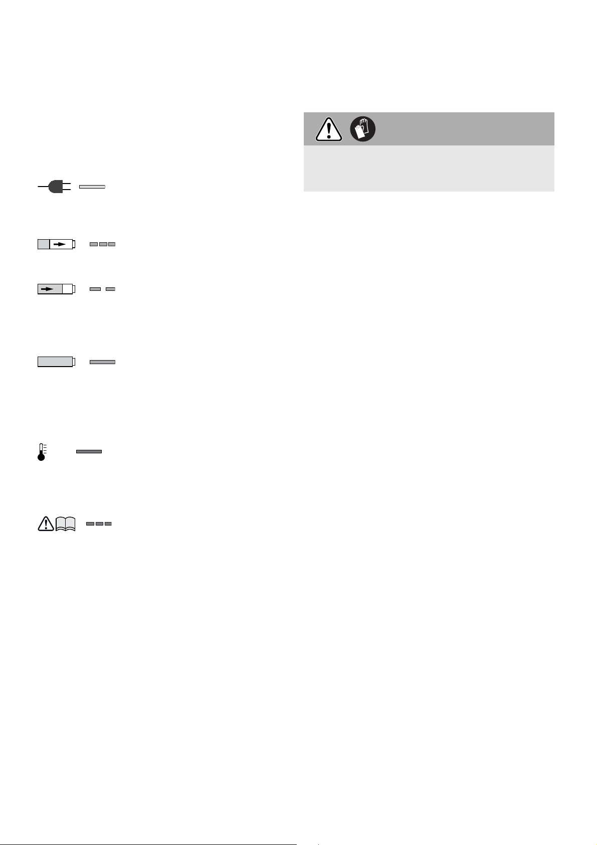
6.2 Замена аккумулятора
Вынимание аккумулятора [2A]
8 Зажатие инструмента из держате-
ля бит
Установка аккумулятора [2B]
Аккумулятор при поставке сразу готов к рабо-
те. Его подзарядка возможна в любое время.
6.3 Зарядка аккумулятора [3]
Светодиод (СД) [3-1] зарядного устрой ства показывает рабочее состояние устройства.
СД, желтый – горит непрерывно
Зарядное устройство готово к
эксплуата ции.
СД, зеленый – часто мигает
Аккумулятор заряжается максимальным током.
СД, зеленый – редко мигает
Аккумулятор заряжается пониженным током, литиевоионные аккумуляторы (LiIon)
заряжаются на 80 %.
СД, зеленый – горит непрерывно
Процесс зарядки завершён
или не запущен, так как текущий уровень зарядки составляет более 80 %.
СД, красный – горит непрерывно
Температура аккумулятора
превышает допустимое значение.
СД, красный – мигает
Общий индикатор неисправности, напр. неправильное замыкание контактов, короткое
замыкание, неисправность
аккумулятора и т. д.
7 Настройка на инстру мент
Настройка должна выполняться только при
состоянии статистического спокойствия аккумуляторного шуруповерта и будет зарегистрирована (акцептована) только после нового запуска.
7.1 Переключение направ ления вращения
[1-3]
Переключение переключателя справа налево
= вращение вправо;
Переключение переключателя слева направо
= вращение влево.
8.1 Держатель бит
Держатель бита позволяет быструю замену бит.
При смене рабочего инструмента существует
опасность получения травмы!
Используйте защитные перчатки!
Установка держателя бита
Переключатель [1-4] установите в положе-
ние MAN (МАН).
Держатель бита [4-2] установите в шести-
гранное отверстие шпинделя [4-4] вставив
его до упора.
Закрепите бит [4-3] в держателе.
После этого установите на редуктор ограни-
читель глубины так, как описано в пункте 9.2.
Снятие держателя бита
Снимите ограничитель глубины способом,
который описан в пункте 9.2.
Держатель силой вытащите из отверстия
шпинделя.
8.2 Смена бута
Для смены бита [1-6] можете применить ограничитель глубины [1-5].
Ограничитель глубины наденьте на бит (смо-
трим рис. [4 b] ).
Заклиниванием ограничителя глубины на
бите и одновременным тянущим усилием бит
можно вытащить.
После этого установите в держатель новый
бит.
ВНИМАНИЕ
9 Ввод в эксплуатацию и эксплуата-
ция
9.1 Включение и выключение
Нажатием всего лишь выключателя [1-2],
включение аккумуляторного шуруповерта
не произойдет – это не является дефектом
электроинструмента!
После завинчивания шурупа на требуемую
глубину аккумуляторный шуруповерт выклю-
чится сам!
Включение аккумуляторного шуруповерта
можно достичь несколькими способами:
а)
Переключателем [1-3] установите вращение
шпинделя вправо.
82
Page 83

Переключатель [1-4] установите в положе-
ние MAN (МАН).
Включите аккумуля торный шуруповерт вы-
ключателем [1-2] и одновременно прижи-
майте бит к шурупу.
Выключателем [1-2] можно обороты плав но
регулировать.
б)
Переключателем [1-3] установите вращение
шпинделя вправо.
Переключатель [1-4] установите в положе-
ние AUTO (АВТО). Включение шуруповерта
достигнете прижатием бита к шурупу.
Нет необходимости включать выключатель [1-
2]. Максимальные обороты устанавливаются
автоматически.
в)
Переключателем [1-3] установите вращение
шпинделя влево.
После включения аккумуляторного шурупо-
верта, ключите выключатель [1-2]. Пере-
ключатель MAN/AUTO (МАН/АВТО) [1-4]
находится в произвольной позиции.
Выключателем [1-2] можно обороты плав но
регулировать.
Если переключателем [1-3] установлено вра-
щение влево, шуруповерт можно запустить
только нажатием выключателя – без допол-
нительного давления на бит!
Для вывинчивания шурупов, снимать огра-
ничитель глубины не обязательно!
9.2 Ограничитель глубины
Вращением ограничителя глубины можно установить глубину завинчивания – смотрим рисунок [5]. Точность установки равна примерно ±
0,1 мм.
Вращение влево = увеличение глубины
завинчивания шурупа
Вращение вправо = уменьшение глубины
завинчивания шурупа.
После настройки глубины, завинтите, с целью
проверки, один шуруп и глубину дорегулируйте.
Установка ограничителя глубины
Установите ограничитель глубины [4-1] на
корпус редуктора [4-5] так, чтобы он слышимо стал на место.
Снятие ограничителя глубины
Приложенным усилием снимите ограничи-
тель глубины с корпуса редуктора.
9.3 Крючок для завешивания и зажим для
крепления на ремень
При помощи зажима [6-1], шуруповерт может
быть временно прикреплен к рабочей одежде.
Применив болты [6-2], зажим можно прикрепить к левой или правой стороне аккумуляторного шуруповерта, что предоставляет удобство
при работе правой или левой рукой – смотрим
рис. [6].
Аккумуляторный шуруповерт оборудован крючком [7-1], который, в случае необходимости,
служит для завешивания электроинструмента.
Крючок, при помощи болтов [7-2], может быть
прикреплен к правой или левой стороне аккумуляторного шуруповерта – смотрим рис. [7].
9.4 Насадка для автомати ческой подачи
шурупов
Насадка для автоматической подачи шурупов
позволяет непрерывную работу, без лишних
перерывов.
Установка насадки для автоматической подачи шурупов
Сначала снимите ограничитель глубины [4-
1], держатель бит [4-2] и бит так, как описано
в пункте 8.
Переключатель [1-4] установите в положе-
ние MAN (МАН).
Бит [8-1] установите в шестигранное отвер-
стие шпинделя, вставив до упора.
После этого установите на корпус редуктора
насадку для автоматической подачи шурупов.
Установка насадки для автоматической по-
дачи шурупов должна быть выполнена так,
чтобы насадка слышимо зашла в бобышку на
корпусе редуктора.
Насадку для автоматической подачи шурупов
можно позиционировать по 30°.
Снятие насадки для автоматической подачи
шурупов
Насадку для автоматической подачи шурупов
осторожно снимем с корпуса редуктора, применив большое тяговое усилие.
Настройка длины шурупов
Нажатием на кнопку [9-1] можно выдвигать
и задвигать ограничитель глубины [9-2] и
этим настроить требуемую длину шурупов.
Настроенную длину шурупов определите на боковых сторонах ограничителя [9-3].
Закладка ленты с шурупами
Ленту с шурупами [10-3] сначала протянем
83
Page 84

нижним направляющим устройством насадки для автоматической подачи шурупов,
далее направляющим устройством каретки,
где шуруп будет стабилизирован в рабочем
положении.
Легко потянув за ленту с шурупами, убеди-
тесь в том, что лента заложена безопасно.
Проверьте, если первый шуруп находится в
оси завинчивания – смотрим рис. [10].
Необходимую глубину завинчивания на-
стройте регулятором [10-1].
Вращением вправо, шурупы завинчиваются
глубже, вращением влево – глубина завинчивания уменьшается. На указателе предварительной настройки [10-2] можно опре-
делить актуальную позицию настройки.
После настройки установите один шуруп для
проверки, а в случае необходимости, регулятором [10-1] выполните донастройку глубины
завинчивания. Каждое изменение настройки
соответствует перемещению ограничителя на
± 0,1 мм.
Рекомендуем выполнять операции завинчи-
вания в автоматическом режиме – смотрим
пункт 9.1 б).
Устранение ленты
Устранение ленты выполняется всего лишь
вытаскиванием в направлении вверх (рис.
[11]
одновременным вытаскиванием ленты в на-
правлении вниз (рис. [11] ).
), или нажатием рычажка подачи с
10 Указания для работы
- Насадку для автоматической подачи шурупов
запрещено держать в области ограничителя
глубины!
- Каждае дозатягивание шурупа должно быть
полностью закончено. Прерванное дозатягивание или ослабление прижимного усилия во
время дозатягивания, может привести к неудовлетворительной функции шуруповерта.
- Ленты с запасными шурупами разрешено за-
менять только при выключенном шуруповерте.
- Ни в коем случае не используйте насадку для
автоматической подачи шурупов иначе, чем
описано в этой инструкции по эксплуатации.
- Применяйте только оригинальные завинчи-
вающие биты.
- Применяйте только оригинальные ленты с
шурупами.
84
- Ленты с шурупами всегда храните в ориги-
нальной упаковке.
- Всегда работайте в правом углу, против при-
крепляемого листа.
Обслуживание насадки автоматической подачи шурупов
Насадка автоматической подачи шурупов, в
сущности, не требует никакого обслуживания.
После длительного использования насадки,
рекомендуем ее вычистить сжатым воздухом.
Насадка для автоматической подачи шурупов
должна быть смазана в зоне направляющей
каретки (см. рис. [12 b]).
Перед очищением, насадку автоматической подачи шурупов демонтируйте способом, который
описан в предшествующих пунктах.
Перед очисткой удалите из насадки автоматической подачи ленту с шурупами так, как описано в
разделе Устранение ленты.
Насадку автоматической подачи шурупов снимите с аккумуляторного шуруповерта.
Снятие каретки
1. Ограничитель глубины [9-2] вдавите в
корпус так, чтобы кнопка арретира [12-1]
была на уровне метки для демонтажа каретки
[12-2] – смотрим рис. [12 a].
2. Нажмите кнопку арретира [12-1] и одновременно вытащите каретку из насадки автоматической подачи – смотрим рис. [12 b].
3. Нажмите кнопку [9-1] и одновременно осво-
бодите ограничитель глубины – смотрим рис.
[12 c].
Снятие рычажка подачи
1. Нажмите кнопку [13-1] и одновременно ее
выдвиньте – смотрим рис. [13 a].
2. Освобожденную кнопку [13-1] (рис. [13 b]) с
рычажком подачи [13-2] и пружиной [13-3]
извлеките из каретки (рис. [13 c]).
Каждую деталь вычистите, дефектные или изношенные детали замените, и смонтируйте в
обратном порядке.
При обратном монтаже рычажка подачи в
каретку, обратите внимание на правильную
установку пружинки кнопки [13-3] в рычажке
подачи. Неправильная установка может стать
причиной неработоспособности подачи лент.
Звуковые сигналы
В следующих случаях раздаются звуковые сигналы и дрель выключается:
ВНИМАНИЕ
Page 85

- Разряжен аккумулятор или
писк
дрель работает с перегрузкой
• Смените аккумулятор.
• Уменьшите нагрузку на дрель.
- Дрель перегрета
писк писк
• После охлаждения дрели
можно снова приступать к работе.
- Перегрет или неисправен ли-
писк писк писк
тиево-ионный аккумулятор
• Проверьте работоспособность
при остывшем аккумулятор с
помощью зарядного устройства.
11 Обслуживание и уход
Опасность несчастного случая, удара током
Перед началом любых работ по уходу и
техническому обслуживанию инструмента
всегда вынимайте аккумуляторный блок!
Любые работы по обслуживанию и ремон-
ту, требующие открытия корпуса двигателя,
могут проводиться только в авторизированных мастерских Сервисной службы.
Сервисное обслуживание и ремонт
только через фирму- изготовителя или
в наших сервисных мастерских: адрес
ближайшей мастерской см. на
www.festool.com/Service
EKAT
4
Используйте только оригинальные за-
5
3
2
1
пасные части Festool! № для заказа на:
www.festool.com/Service
Соблюдайте следующие указания:
- Следите за чистотой вентиляционных прорезей на электроинструменте и зарядном
устройстве для обеспечения охлаждения.
- Следите за чистотой соединительных контактов на электроинструменте, зарядном
устройстве и аккумуляторе.
Указания, касающиеся аккумуляторов
– Храните инструмент в сухом, прохладном ме-
сте при температуре между 5 °C и 25 °C.
– Предохраняйте аккумуляторы от воздействия
влаги, воды и высоких температур.
– Не оставляйте разряженные аккумуляторы
в отключённом от сети зарядном устройстве
дольше, чем на месяц. Опасность глубокого
разряда!
– При длительном хранении литий-ионных ак-
кумуляторов без использования они должны
ПРЕДУПРЕЖДЕНИЕ
быть заряжены на 40 % (ок. 15 мин подзарядки).
– Для предотвращения опасности короткого
замыкания аккумулятор необходимо хранить
в прилагаемой упаковке.
– Заметное сокращение времени работы после
зарядки указывает на необходимость замены
аккумулятора.
12 Транспортировка
Эквивалентное количество лития в литиевоионном аккумуляторе находится ниже соответствующих предельных значений и проверяется в соответствии с руководством ООН ST/SG/
AC.10/11/Ревю 3 часть III, подраздел 38.3. Поэтому литие во-ионный аккумулятор, ни отдельно, ни установленный в дрель, не подпадает под
национальные и международные требования к
опасным грузам. Однако требования к опасным
грузам могут иметь силу при транспортировке
нескольких аккумуляторов. В этом случае необходимо выполнить специальные требования.
Подробную информацию для Европейского Союза можно найти в особом предписании ADR
230.
13 Опасность для окружающей сре-
ды
Не выбрасывайте инструмент вместе с бытовыми отходами! Обеспечьте безопасную для
окружающей среды утилизацию инструментов,
оснастки и упаковки. Соблюдайте действующие
национальные предписания!
Только для ЕС: согласно Европейской директиве
2002/96/EG отслужившие свой срок электроинструменты должны утилизироваться отдельно от
других отходов направляться на экологически
безопасную утилизацию.
Сдавайте отслужившие свой срок или неис-
правные аккумуляторы в специализированную
торговлю, сервисную службу Festool или в предписанные государством предприятия по сбору,
уничтожению, обезвреживанию и утилизации
отходов. (соблюдайте действующие национальные предписания). При возврате аккумуляторы
должны находиться в разряженном состоянии.
Так аккумуляторы подвергаются переработке в
установленном порядке.
Только для ЕС: в соответствии с Европейской
директивой 91/157/EWG неисправные или отслужившие свой срок аккумуляторы/батареи
подлежат вторичной переработке.
Информация по директиве REACh:
www.festool.com/reach
85
Page 86

14 Декларация соответствия ЕС
Аккумуляторный шуруповерт
для гипсокартона
DWC 18-2500 767850
DWC 18-4500 767898
Год маркировки CE: 2013
С исключительной ответственностью мы заявляем, что настоящее изделие соответствует
следующим нормам или нормативным документам:
2006/42/EG, 2004/108/EG, 2011/65/UE, EN 550141, EN 55 014-2, EN 60745-1, EN 60745-2-2, EN
61000-3-2, EN 61 000-3-3.
Зарядное устройство Серийный №
TCL 3 10002345, 10004911
Год маркировки CE: 2013
Серийный
№
С исключительной ответственностью мы заявляем, что настоящее изделие соответствует
следующим нормам или нормативным документам:
2004/108/EG, 2006/95/EG, 2011/65/UE, EN 603351, EN 60335-2-29, EN 61000-3-2, EN 61000-3-3,
EN 61204-3.
Festool Group GmbH & Co. KG
Wertstr. 20, D-73240 Wendlingen, Germany
Dr. Martin Zimmer
Руководитель отдела исследований и разработок, технической документации
2013-04-15
86
Page 87

Originální návod k použití
CZ
1 Bezpečnostní pokyny
1.1 Všeobecné bezpečnostní pokyny
Výstraha! Přečtěte si všechny bezpečnostní pokyny a instrukce.
Chyba při dodržování varovných upozornění a instrukcí může způsobit zásah
elektrickým proudem, požár a/nebo vážné zranění.
Všechny bezpečnostní pokyny a instrukce uschovejte, abyste je mohli použít i v
budoucnosti.
Pojem „elektrické nářadí“, používaný v bezpečnostních pokynech, se vztahuje na
síťové elektrické nářadí (se síťovým kabelem) a na akumulátorové nářadí (bez
síťového kabelu).
1.2 Bezpečnostní pokyny specifi cké pro dané nářadí
- Pokud provádíte práce, při kterých může šroub narazit na skrytá elektrická ve-
dení, držte nářadí pouze za izolované plochy rukojeti. Pokud se šroub dostane do
kontaktu svedením pod napětím, mohou se pod napětím ocitnout ikovové části
nářadí, což může mít za následek zásah elektrickým proudem.
- Tuto nabíječku mohou používat děti od 8 let a osoby se sníženými fyzickými, sen-
zorickými či mentálními schopnostmi nebo s nedostatkem zkušeností a vědomostí
pouze pod dohledem, nebo pokud byly zasvěceny do bezpečného použití přístroje a
chápou hrozící nebezpečí. Děti si s přístrojem nesmějí hrát. Čištění a uživatelskou
údržbu nesmí provádět děti bez dohledu.
-
Používejte vhodné osobní ochranné pomůcky: ochranu
sluchu, ochranné brýle, respirátor při činnostech, kdy
dochází ke vzniku prachu, pracovní rukavice při opraco-
vávání hrubých materiálů nebo při výměně nástroje.
- Při šroubování do zdí je nutno dbát na eventuální plynové a vodovodní trubky a
dále elektrické kabely.
- Akumulátor a nabíječku neotevírejte!
- Chraňte nabíječku před kovovými předměty a částicemi (např. kovovými šponami)
a kapalinami!
- Nepoužívejte jiné akumulátory a jiné nabíječky!
- Akumulátor chraňte před horkem, např. také před trvalým slunečním zářením
a ohněm!
- Hořící lithium-iontové akumulátory nikdy nehaste vodou! Použijte písek nebo
hasicí deku.
- Kontrolujte pravidelně síťovou zástrčku a kabel a při poškození je nechte vyměnit
v autorizovaném zákaznickém servisu.
- Spojením zásobníku a akušroubováku vzniká zařízení, pro které platí bezpeč-
nostní předpisy a a pokyny pro akušroubovák.
87
Page 88

1.3 Hlučnost a vibrace
Hodnoty zjištěné dle EN 60 745 jsou typicky:
Hladina akustického tlaku L
Hladina akustického výkonu L
= 78 dB (A)
PA
= 89 dB (A)
WA
Nepřesnost měření K = 3 dB
Ke zvýšení může dojít při jiném použití, s jinými
nástroji nebo při nedostatečné údržbě. Vezměte
v úvahu čas, kdy nářadí běží na volnoběh a kdy je
vypnuté!
2 Symboly
POZOR
Vdechovaný prach může poškodit dýchací cesty.
V případě prašných prací noste respirátor.
Celkové hodnoty vibrací (součet vektorů tří směrů)
zjištěné podle EN 60 745:
DWC 18-2500
Hodnota vibrací (3 osy) a
= 2,8 m/s
h
Nepřesnost měření K = 1,5 m/s
DWC 18-4500
Hodnota vibrací (3 osy) a
= 3,5 m/s
h
Nepřesnost měření K = 1,5 m/s
Uvedené emitované hodnoty (vibrace, hlučnost)
– slouží k porovnání nářadí,
– jsou vhodné také pro předběžné posouzení za-
tížení vibracemi a hlukem při použití nářadí,
– vztahují se k hlavním druhům použití elektric-
kého nářadí.
Varování před všeobecným nebezpečím
Nebezpečí úrazu elektrickým proudem
Přečtěte si návod/pokyny!
2
2
Používejte respirátor!
Noste chrániče sluchu!
2
2
Používejte ochranu očí!
Noste ochranné rukavice!
Nepatří do komunálního odpadu.
Upozornění, rada
3 Technické údaje
Akušroubovák pro sádrokarton DWC 18-2500 DWC 18-4500
Napětí motoru 18 V 18 V
Otáčky naprázdno* 0 – 2500/min 0 – 4500/min
Kroutící moment (měkký / tvrdý) 7 / 18 Nm 5 / 14 Nm
Upnutí nástroje ve vřetenu ¼“ DIN 3126 / ISO 1173
Hmotnost (bez akumulátoru) 1,1 kg 1,1 kg
Hmotnost s hloubkovým dorazem (bez akumulátoru) 1,2 kg 1,2 kg
Hmotnost se zásobníkem (bez akumulátoru) 1,5 kg 1,5 kg
Nabíječka TCL 3
Síťové napětí (vstupní) 220 - 240 V ~
Síťová frekvence 50/60 Hz
Nabíjecí napětí (výstupní) 10,8–18 V=
Rychlonabíjení max. 3 A
Udržovací dobíjení pulzní (NiCd, NiMH)
cca 0,06 A
Doby nabíjení pro akumulátory BP, BPS a BPC
LiIon 1,5 Ah, 80 %/100 % cca 25/35 min
LiIon 3,0 Ah, 80 %/100 % cca 55/70 min
LiIon 4,2 Ah, 80 %/100 % cca 70/90 min
Přípustný rozsah provozní teploty –5 °C až + 45 °C
Sledování teploty pomocí odporu NTC
Třída bezpečnosti
/ II
Akumulátor BPC 18 Li
Napětí 18 V
Kapacita 4,2 Ah
Hmotnost 0,7 kg
* Údaje ohledně otáček jsou s plně nabitým akumulátorem.
4 Ovládací prvky
[1-1] Zásobník bitů
[1-2] Spínač
[1-3] Přepínač chodu vpravo a vlevo
[1-4] Přepínač AUTO/MAN
[1-5] Hloubkový doraz
[1-6] Bit
88
Page 89

[3-1] Kontrolka LED
[3-2] Naviják kabelu
[3a] Upevnění na stěnu
Vyobrazené nebo popsané příslušenství nemusí
být součástí dodávky. Uvedené obrázky se nacházejí na začátku návodu k použití.
5 Účel použití
Montážní šroubovák je určen pro následující práce:
Hlavní použití Typ šroubů Typ
DWC 18-2500
DWC 18-4500
Sádrokartonové
desky na kovové
profi ly
(≤0,88mm)
Sádrokartonové
desky na kovové
profi ly
(≤ 2,25 mm)
Sádrokartonové
desky na dřevě né
konstrukce
Sádrovláknité
desky na kovové
a dřevěné konstrukce
Dřevotřískové
desky/OSB pro
dřevěné konstrukce
Rychlomontážní
stavební šrouby s
jemným závitem
Rychlomontážní
stavební šrouby s
navrtávacím hrotem
Rychlomontážní
stavební šrouby s
hrubým závitem
Rychlomontážní
stavební šrouby
pro sádrovláknité
desky
Vruty do
5mm
×
×
×
×
×
Akumulátor je při dodání ihned připravený k
použití a lze ho kdykoli nabíjet.
6.3 Nabíjení akumulátoru [3]
Kontrolka LED [3-1] nabíječky indikuje příslušný
provozní stav nabíječky.
LED žlutá – svítí trvale
Nabíječka je připravena k provozu.
LED zelená – rychle bliká
Akumulátor se nabíjí maximálním proudem.
LED zelená – pomalu bliká
Akumulátor se nabíjí omezeným proudem, li thium-iontový
akumulátor je nabitý na 80%.
LED zelená – svítí trvale
Nabíjení skončilo, nebo se už
znovu nespustí, protože aktuální stav nabití je vyšší než 80 %.
LED červená – svítí trvale
Teplota akumulátoru překročila
přípustné mezní hodnoty.
LED červená – bliká
Indikace obecné chyby, např.
nedokonalý kontakt, zkrat, vadný akumulátor atd.
7 Nastavení na nářadí
Nastavení by měla být prováděna pouze za kli-
du stroje a budou zaregistrována (akceptována)
až po novém spuštění.
7.1 Přepínání směru otáčení [1-3]
Přepínač zprava doleva = chod vpravo;
přepínač zleva doprava = chod vlevo.
Nabíječka TCL 3 se hodí
– pro nabíjení akumulátorů: Festool BPS a BPC
(automaticky se rozpozná NiMH, NiCd, Li-Ion),
– jen pro použití ve vnitřním prostředí.
Při použití v rozporu s určeným účelem
nese odpovědnost uživatel; patří sem také
nepřetržitý průmyslový provoz.
6 Akumulátor
6.1 Navíjení kabelu nabíječky [3-2]
Před uvedením do provozu je nutné celý
kabel odvinout z prohlubně.
6.2 Výměna akumulátoru
Vyjmutí akumulátoru [2A]
Nasazení akumulátoru [2B]
8 Upnutí nástroje, zásobníku
8.1 Držák bitu
Držák bitu umožňuje rychlou výměnu bitů.
Při výměně nástroje hrozí pořezání!
Noste ochranné rukavice!
Montáž držáku bitu
Přepínač [1-4] nastavte do polohy MAN.
Držák bitu [4-2] nasaďte na doraz do šesti-
hranného otvoru vřetena [4-4].
Do držáku upněte bit [4-3].
Poté nasaďte na převodovou skříň hloubkový
doraz jak je popsáno v bodě 9.2.
POZOR
89
Page 90

Demontáž držáku bitu
Sejměte hloubkový doraz dle popisu v bodu 9.2.
Držák silou vytáhnětete z otvoru vřetena.
Montáž hloubkového dorazu
Nasaďte hloubkový doraz [4-1] na převodovou
skříň [4-5], dokud slyšitelně nezapadne.
8.2 Výměna bitu
K výměně bitu [1-6] můžete použít hloubkový doraz [1-5].
Hloubkový doraz nasaďte na bit (viz obr. [4 b] ).
Vzpříčením hloubkového dorazu s bitem a sou-
časným tažením je možné bit vytáhnout.
Poté nasaďte do držáku nový bit.
9 Uvedení do chodu a provoz
9.1 Zapnutí a vypnutí
Pouhým stisknutím spínače [1-2] ne dojde ke
spuštění stroje – není vadou stroje!
Po zašroubování na požadovanou hloubku stroj
sám vypne!
Zapnutí stroje lze dosáhnout několika způsoby:
a)
Přepínačem [1-3] nastavte pravý chod stroje.
Přepínač [1-4] nastavte do polohy MAN.
Pro zapnutí stroje zapněte spínač [1-2] asou-
časně tlačte bitem na šroub.
Spínačem [1-2] lze plynule regulovat otáčky.
b)
Přepínačem [1-3] nastavte pravý chod stroje.
Přepínač [1-4] nastavte do polohy AUTO.
Zapnutí stroje docílíte zatlačením bitu na šroub.
Není nutno zapínat spínač [1-2]. Auto maticky jsou
nastaveny maximální otáčky.
c)
Přepínačem [1-3] nastavte levý chod stroje.
Pro zapnutí stroje zapněte spínač [1-2]. Pře-
pínač MAN/AUTO [1-4] je v libovolné poloze.
Spínačem [1-2] lze plynule regulovat otáčky.
Pokud je přepínačem [1-3] nastaven levý chod,
lze šroubovák uvést do cho du pouhým stisknutím spínače – bez dodatečného tlaku na bit!
K vyšroubování šroubů tudíž nemusí být de-
montován hloubkový doraz!
9.2 Hloubkový doraz
Otáčením hloubkového dorazu lze nastavit hloubku zašroubování – viz obrázek [5]. Přesnost nastavení je ca ±0,1mm.
Otočení doleva = šroub se zapouští
hlouběji
Otočení doprava = šroub se zapouští do
menší hloubky
Po nastavení hloubky usaďte jeden šroub na
zkoušku a hloubku dolaďte.
Demontáž hloubkového dorazu
Hloubkový doraz silou stáhněte z převodové
skříně.
9.3 Hák na zavěšení a svorka
Pomocí svorky [6-1] může být šroubovák do časně
upnut na pracovní oděv – lze jej při pevnit pomocí
šroubu [6-2] na stroj zleva nebo zprava a je tak
vhodný pro praváky ileváky – viz obr. [6].
Šroubovák je vybaven hákem [7-1], který slouží k
příležitostnému zavěšení stroje. Může být upevněn na stroj vlevo nebo vpravo, a to pomocí šroubu
[7-2] – viz obr. [7].
9.4 Zásobník šroubů
Zásobník umožňuje pracovat průběžně, bez zbytečných přestávek.
Nasazení zásobníku
Nejprve sejměte hloubkový doraz [4-1], držák
bitu [4-2] a bit, jak je popsáno vbo dě8.
Přepínač [1-4] nastavte do polohy MAN.
Bit [8-1] nasaďte na doraz do šestihranného
otvoru vřetena.
Poté nasaďte na převodovou skříň zásobník.
Osazení zásobníku musí zapadnout slyšitelně
do výstupků na převodové skříni.
Zásobník lze polohovat po 30°.
Sejmutí zásobníku
Silným tahem opatrně sejměte zásobník zpře-
vodové skříně.
Nastavení délky šroubu
Tlakem na tlačítko [9-1] lze vysouvat aza-
souvat hloubkový doraz [9-2] a tím nastavit
požadovanou délku šroubů.
Nastavenou délku šroubů odečtěte na bočních
stranách dorazu [9-3].
Vložení pásku se šrouby
Pásek se šrouby [10-3] protáhněte nejprve
spodním vedením zásobníku, pak vedením
saní, kde šroub zapadne do pracovní polohy.
Lehkým tahem za pásek se ujistěte, že je pásek
bezpečne usazen. Zkontrolujte, zda je první šroub
v ose šroubování – viz obr.[10].
Potřebnou hloubku šroubování si nastavte ko-
lečkem [10-1].
Otáčením doprava se šrouby usazují hlouběji,
otáčení doleva se vysunují. Na ukazateli před-
volby [10-2] je možné odečíst aktuální polohu
nastavení.
90
Page 91

Po nastavení usaďte jeden šroub na zkoušku a
kolečkem [10-1] hloubku případně dolaďte. Každá změna nastavení odpovídá posunutí dorazu
o ± 0,1 mm.
Doporučujeme šroubovat v automatickém re-
žimu – viz bod 9.1 b).
Vysunutí pásku
Vysunutí pásku se provádí pouhým tahem smě-
rem vzhůru (obr. [11]
) nebo stiskem transportní páčky a současným tahem pásku směrem dolů (obr. [11] ).
10 Pokyny pro práci
- Zásobník nesmí být držen v oblasti hloubkového
dorazu!
- Každé dotahování šroubu musí být dokončeno.
Přerušené dotahování nebo uvolnění přítlaku
během dotahování může vést k neuspokojivé
funkci přístroje.
- Pásky se zásobními šrouby se smí vyměňovat
pouze pokud je stroj vypnutý.
- V žádném případě nepoužívejte zásobník jinak,
než je popsáno v tomto návodě pro používání.
- Používejte pouze originální šroubovací bity.
- Používejte pouze originální páskované šrouby.
- Pásky se šrouby skladujte vždy v originálním
balení.
- Pracujte vždy v pravém úhlu proti upevňované
desce.
Údržba zásobníku
Zásobník v podstatě nevyžaduje žádnou údržbu.
Po dlouhodobějším používání jej doporučujeme
vyčistit tlakovým vzduchem.
Zásobník je možno mazat v oblasti vedení saní –
viz obrázek [12 b].
Před čištěním demontujte zásobník, jak je popsáno v předešlých bodech.
Před čištěním vyjměte ze zásobníku pásek se
šrouby, jak je popsáno v článku Vysunutí pásku.
Zásobník sejměte ze šroubováku.
Demontáž transportní páčky
1. Stiskněte tlačítko [13-1] a současně jej vysuňte
– viz obr. [13 a].
2. Uvolněné tlačítko [13-1] (obr. [13 b]) strans-
portní pákou [13-2] a pružinou [13-3] vyjměte
ze saní (obr. [13 c]).
Jednotlivé díly vyčistěte, vadné nebo opotřebované
díly vyměňte a smontujte v obráceném sledu.
POZOR
Při zpětné montáži trasportní páčky do saní
dbejte na správné usazení pružinky tlačítka
[13-3] v transportní páčce. Nesprávná montáž
může způsobit nefunkčnost transportu pásků.
Výstražné akustické signály
Při následujících provozních stavech zazní vý stražné
akustické signály a nářadí se vypne:
- Vybitý akumulátor nebo přetížené
píp
nářadí.
• Vyměňte akumulátor.
• Zmírněte zatížení nářadí.
- Nářadí je přehřáté.
píp píp
• Po vychladnutí můžete nářadí znovu uvést do provozu.
- Lithium-iontový akumulátor je pře-
píp píp píp
hřátý nebo vadný.
• Pomocí nabíječky zkontrolujte
funkčnost vy chladlého akumulátoru.
11 Údržba a péče
Nebezpečí úrazu elektrickým proudem
Před prováděním veškerých prací údržby a
opravách vždy z nářadí vyjměte akumulátor.
Veškerou údržbu a opravy, které vyžadují
otevření krytu motoru, smí provádět pouze
autorizovaný zákaznický servis.
VÝSTRAHA
Demontáž saní
1. Hloubkový doraz [9-2] zatlačte do skříně tak,
aby aretační tlačítko [12-1] bylo na úrovni značky pro demontáž saní [12-2] – viz obr. [12 a].
2. Stlačte aretační tlačítko [12-1] a současně vytáhněte saně ze zásobníku – viz obr. [12 b].
3. Stiskněte tlačítko [9-1] a současně uvolněte
hloubkový doraz – viz obr. [12 c].
Servis aopravy smí provádět pouze výrobce nebo servisní dílny: nejbližší adresu najdete na:
www.festool.com/Service
EKAT
4
Používejte jen originální náhradní díly
5
3
2
1
Festool! Obj. č. na:
www.festool.com/Service
91
Page 92

Dodržujte následující pokyny:
- Chladicí otvory elektrického nářadí a na bíječky
udržujte čisté, aby bylo zajištěno chlazení.
- Připojovací kontakty elektrického nářadí, nabíječky a akumulátoru udržujte čisté.
Pokyny pro akumulátory
– Skladujte na suchém, chladném místě při tep-
lotě od 5 °C do 25 °C.
– Akumulátory chraňte před vlhkem, vodou a
horkem.
– Vybité akumulátory nenechávejte v nabíječce
déle než cca měsíc, pokud je nabíječka odpojená od sítě. Nebezpečí hlubokého vybití!
– Pokud se lithium-iontové akumulátory skladují
delší dobu bez používání, měly by být nabité na
40 % kapacity (doba nabíjení cca 15 min).
– Aby nedošlo ke zkratu, měli byste akumulátor
skladovat v obalu, který je součástí dodávky.
– Výrazně kratší doba chodu na jedno nabití aku-
mulátoru signalizuje, že je akumulátor opotřebovaný a je nutné ho vyměnit za nový.
12 Přeprava
Množství ekvivalentu lithia obsaženého v lithiumiontovém akumulátoru je pod příslušnou mezní
hodnotou a je zkontrolováno podle dokumentu
OSN ST/SG/AC.10/11/Rev.3 část III, odstavec 38.3.
Proto lithium-iontový akumulátor nepodléhá ani
jako samostatný díl ani nasazený v nářadí národním a mezinárodním předpisům pro přepravu
nebezpečných látek. Předpisy pro přepravu nebezpečných látek mohou být ovšem relevantní při
přepravě většího množství akumulátorů. V tomto
případě může být nutné dodržovat zvláštní podmínky.
Staré nebo vadné akumulátory odevzdávejte ve
specializovaných odborných obchodech, zákaznickém servisu Festool nebo úředně pověřených
zařízeních pro likvidaci. (Dodržujte předpisy platné ve vaší zemi.) Akumulátory musí být při vracení vybité. Akumulátory jsou pak předány k řádné
recyklaci.
Pouze EU: Podle evropské směrnice 91/157/EHS
musí být vadné nebo staré akumulátory/baterie
recyklovány.
Informace k REACh: www.festool.com/reach
14 ES prohlášení o shodě
Akušroubovák pro sádrokarton Sériové
číslo
DWC 18-2500 767850
DWC 18-4500 767898
Rok označení CE: 2013
Prohlašujeme s plnou naší zodpovědností, že tento výrobek je v souladu s následujícími normami
nebo normativními dokumenty:
2006/42/ES, 2004/108/ES, 2011/65/UE, EN 550141, EN 55 014-2, EN 60745-1, EN 60745-2-2, EN
61000-3-2, EN 61 000-3-3.
Nabíječka Sériové číslo
TCL 3 10002345, 10004911
Rok označení CE: 2013
Prohlašujeme s plnou naší zodpovědností, že tento výrobek je v souladu s následujícími normami
nebo normativními dokumenty:
2004/108/ES, 2006/95/ES, 2011/65/UE, EN 603351, EN 60335-2-29, EN 61000-3-2, EN 61000-3-3,
EN 61204-3.
13 Životní prostředí
Nářadí nevyhazujte do domovního odpadu! Ná-
řadí, příslušenství a obaly odevzdejte k ekologické
recyklaci. Dodržujte platné národní předpisy.
Pouze EU: Podle evropské směrnice 2002/96/ES
se musí stará elektrická zařízení třídit a odevzdávat k ekologické recyklaci.
92
Festool Group GmbH & Co. KG
Wertstr. 20, D-73240 Wendlingen, Germany
Dr. Martin Zimmer
Vedoucí výzkumu, vývoje, technické dokumentace
2013-04-15
Page 93

Oryginalna instrukcja eksploatacji
PL
1 Zalecenia dotyczące bezpieczeństwa pracy
1.1 Ogólne zalecenia bezpieczeństwa
Ostrzeżenie! Należy przeczytać wszystkie zalecenia bezpieczeństwa pracy
i instrukcje.Nieprzestrzeganie ostrzeżeń i instrukcji może spowodować po-
rażenie elektryczne, pożar oraz/lub ciężkie obrażenia.
Wszystkie zalecenia odnośnie bezpieczeństwa pracy i instrukcje należy zachować
do wykorzystania w przyszłości.
Używane w zaleceniach bezpieczeństwa pracy pojęcie „Narzędzie elektryczne“
odnosi się do narzędzi elektrycznych zasilanych z sieci (z przewodem zasilającym)
i do narzędzi elektrycznych zasilanych z akumulatora (bez przewodu zasilającego).
1.2 Zalecenia dotyczące bezpieczeństwa specyfi czne dla danego narzędzia
- Podczas wykonywania prac, przy których śruba może zetknąć się z ukrytymi
przewodami przewodzącymi prąd, należy chwytać urządzenie wyłącznie za
izolowane powierzchnie uchwytów. Po zetknięciu śruby z przewodem przewodzą-
cym napięcie metalowe części urządzenia mogą także znaleźć się pod napięciem
i doprowadzić do porażenia prądem.
- Ładowarka ta może być używana przez dzieci od lat 8 i więcej, jak również przez
osoby o ograniczonych zdolnościach fi zycznych, sensorycznych lub umysłowych
lub też o ograniczonym doświadczeniu i wiedzy, jeśli są one pod nadzorem, zostały
poinstruowane o sposobie bezpiecznego użytkowania urządzenia i rozumieją wynikające w związku z tym zagrożenia. Dzieci nie mogą bawić się tym urządzeniem.
Dzieci nie mogą wykonywać czyszczenia i konserwacji bez nadzoru.
-
Należy stosować odpowiednie osobiste wyposażenie
zabezpieczające: ochronę słuchu, okulary ochronne, ma-
skę przeciwpyłową przy pracach związanych z pyleniem,
rękawice ochronne przy pracach z materiałami szorstkimi oraz przy wymianie
narzędzia.
- Wkręcając wkręty w ściany należy uważać na ewentualne rury gazowe, przewody
elektryczne i wodociągowe.
- Nie otwierać akumulatora i ładowarki!
- Chronić ładowarkę przed elementami metalowymi (np. wiórami metalowymi) lub
też cieczami!
- Nie używać innych akumulatorów oraz ładowarek!
- Chronić akumulator przed wysoką temperaturą, np. przed długotrwałym promieniowaniem słonecznym oraz przed ogniem!
- Nigdy nie gasić palących się akumulatorów LiIon wodą! Użyć piasku lub koca
gaśniczego.
- W regularnych odstępach czasu należy sprawdzać wtyczkę i przewód, a w przypadku uszkodzenia należy zlecić ich wymianę autoryzowanemu warsztatowi serwisowemu.
93
Page 94

- Z połączenia zasobnika i wkrętarki akumulatorowej powstaje urządzenie, którego
dotyczą przepisy bezpieczeństwa dla wkrętarek akumulatorowych.
1.3 Parametry emisji
Wartości określone na podstawie normy
EN 60 745 wynoszą w typowym przypadku:
Poziom ciśnienia akustycznego L
= 78 dB (A)
PA
Poziom mocy akustycznej LWA = 89 dB (A)
Plus margines błędu pomiaru K = 3 dB
OSTROŻNIE
Hałas powstający podczas pracy może
uszkodzić słuch.
Należy stosować ochronę słuchu!
Wartości całkowite wibracji (suma wektorowa w
trzech kierunkach) określone zgodnie z normą
EN 60 745:
DWC 18-2500
Wartość emisji wibracji (3-osiowo) a
= 2,8 m/s
h
Niepewność pomiaru K = 1,5 m/s
DWC 18-4500
Wartość emisji wibracji (3-osiowo) ah = 3,5 m/s
Niepewność pomiaru K = 1,5 m/s
Podane wartości emisji (wibracje, szmery)
– służą do porównania narzędzi,
– nadają się one również do tymczasowej oce-
ny obciążenia wibracjami i hałasem podczas
użytkowania.
– odnoszą się do głównych zatosowań tego elek-
tronarzędzia.
Wartości te mogą być wyższe w przypadku innych
zastosowań, w przypadku pracy z innym osprzętem oraz w przypadku niewłaściwej konserwacji.
Należy uwzględnić czas pracy urządzenia na biegu
jałowym oraz czas unieruchomienia!
2 Symbole
Ostrzeżenie przed ogólnym zagrożeniem
Niebezpieczeństwo porażenia prąde
Przeczytać instrukcję/zalecenia!
Należy nosić maskę przeciwpyłową!
2
2
2
2
Zalecenie, wskazówka
Należy nosić ochronę słuchu!
Nosić okulary ochronne!
Należy nosić rękawice ochronne!
Nie wyrzucać do odpadów komunalnych.
3 Dane techniczne
Wkrętarka akumulatorowa do płyt
gipsowo-kartonowych DWC 18-2500 DWC 18-4500
Napięcie silnika 18 V 18 V
Obroty bez obciążenia* 0 – 2500/min 0 – 4500/min
Moment obrotowy (miękki / twardy) 7 / 18 Nm 5 / 14 Nm
Uchwyt narzędziowy ¼” DIN 3126 / ISO 1173
Ciężar (bez akumulatorem) 1,1 kg 1,1 kg
Ciężar z ogranicznikiem głębokości
(bez akumulatorem) 1,2 kg 1,2 kg
Ciężar z zasobnikiem (bez akumulatorem) 1,5 kg 1,5 kg
Ładowarka TCL 3
Napięcie sieciowe (wejście) 220 - 240 V ~
Częstotliwość sieciowa 50/60 Hz
Napięcie ładowania (wyjście) 10,8 - 18 V=
Ładowanie szybkie maks. 3 A
ładowanie podtrzymujące prądem
pulsującym (NiCd, NiMH) ok. 0,06 A
94
Czasy ładowania dla akumulatorów BP, BPS i BPC
LiIon 1,5 Ah, 80 %/ 100 % ok. 25/35 min.
LiIon 3,0 Ah, 80 %/ 100 % ok. 55/70 min.
LiIon 4,2 Ah, 80 %/ 100 % ok. 70/90 min.
Dopuszczalny zakres temperatury
roboczej -5 °C do + 45 °C
Kontrola temperatury za pomocą tyrystora
o ujemnym współczynniku temperaturowym
Klasa zabezpieczenia
/ II
Page 95

Akumulator BPC 18 Li 1
Napięcie 18 V
Pojemność 4,2 Ah
Ciężar 0,7 kg
* Dane dotyczące prędkości obrotowej przy całkowicie naładowanym akumulatorze.
3 Elementy urządzenia
[1-1] Zasobnik bitów
[1-2] Włącznik
[1-3] Przełącznik obrotów w prawo i w lewo
[1-4] Przełącznik AUTO/MAN
[1-5] Ogranicznik głębokości
[1-6] Bit
[3-1] Wskaźnik diodowy
[3-2] Uchwyt do nawijania kabla
[3a] Mocowanie na ścianie
Przedstawione lub opisane wyposażenie częściowo nie wchodzi w skład dostawy.
Podane rysunki znajdują się w załączniku instrukcji obsługi.
5 Użycie zgodne z przeznaczeniem
Wkrętarka akumulatorowa do płyt gipsowo-kartonowych przeznaczona jest do wykonywania następujących prac:
Główne za stosowanie Rodzaje śrub Typ
DWC 18-2500
Płyty gipsowo-kartonowe do profi li metalowych (≤ 0,88 mm)
Płyty gipsowo-kartonowe do profi li metalowych (≤ 2,25 mm)
Płyty gipsowokartonowe do
konstrukcji
drewnianych
Płyty gipsowo-pilśniowe do konstrukcji
metalowych i drewnianych
Płyty wiórowe /
OSB do konstruk cji
drewnianej
Wkręty samowiercące z
gwintem drobnozwojowym
Wkręty samowiercące z
końcówką
wiercącą
Wkręty samowiercące z
gwintem grubozwojowym
Wkręty samowiercące z
gwintem nacinającym
Wkręty do płyt
drewnianych i
wiórowych do
5mm
×
×
×
×
×
Ładowarka TCL 3 nadaje się
– do ładowania akumulatorów: Festool BPS i
BPC (akumulatory NiMH, NiCd, LiIon są rozpoznawane automatycznie),
– tylko do użytku w pomieszczeniach.
W przypadku eksploatacji niezgodnej z
przeznaczeniem odpowiedzialność ponosi użytkownik.; dotyczy to również przemysłowej pracy ciągłej.
6 Uruchomienie
6.1 Uchwyt do nawijania kabla na ładowarce
[3-2]
Przed uruchomieniem kabel należy cał-
kowicie odwinąć z wycięcia.
6.2 Wymiana akumulatora
Wyjmowanie akumulatora [2A]
Wkładanie akumulatora [2B]
Akumulator jest w momencie dostawy goto-
wy do natychmiastowego użytku i można go w
każdej chwili naładować.
6.3 Ładowanie akumulatora [3]
Dioda LED [3-1] ładowarki wskazuje aktual ny
stan roboczy ładowarki.
Żółta dioda LED – świecenie
ciągłe
Ładowarka jest gotowa do pracy.
Zielona dioda LED – szybkie
miganie
DWC 18-4500
Akumulator ładowany jest z
maksymalnym natężeniem prądu.
Zielona dioda LED – wolne miganie
Akumulator ładowany jest ze
zmniejszonym natężeniem prądu, akumulator Li Ion naładowany jest w 80 %.
Zielona dioda LED – świecenie
ciągłe
Proces ładowania został zakończony lub też nie zostanie
ponownie uruchomiony, ponieważ aktualny stał naładowania
wynosi ponad 80 %..
Czerwona dioda LED – świecenie ciągłe
Temperatura akumulatora przekroczyła dopuszczalną wartość
graniczną.
95
Page 96
Czerwona dioda LED – miganie
Ogólne wskazanie zakłócenia,
np.: brak peł nego styku, zwarcie, uszkodzenie akumulatora,
itp.
7 Ustawienia na urządzeniu
Ustawienia powinny być przeprowadzane tyl-
ko wówczas, gdy urządzenie jest zatrzymane
i staną się aktywne dopiero po jego ponowym
uruchomieniu.
7.1 Przełączanie kierunku obrotów [1-3]
Przełącznik w lewo = prawe obroty;
przełącznik w prawo = lewe obroty.
8 Wymiana narzędzi
8.1 Uchwyt bitów
Uchwyt bitów umożliwia szybką wymianę bitów.
Podczas wymiany narzędzia istnieje niebezpieczeństwo skaleczenia!
Nosić rękawice ochronne!
Montaż uchwytu bitów
Przełącznik [1-4] ustawić w pozycji MAN.
Uchwyt bitów [4-2] wsunąć do oporu w uchwyt
narzędziowy [4-4].
W uchwycie umieścić bit [4-3].
Następnie umieścić na obudowie przekładni
ogranicznik głębokości w sposób opisany w
punkcie 9.2.
Demontaż uchwytu bitów
Zdjąć ogranicznik głębokości według opisu w
punkcie 9.2.
Silnym pociągnięciem wyjąć uchwyt bitów z
uchwytu narzędziowego.
8.2 Wymiana bitów
Do wymiany bitów [1-6] można użyć ogranicznika
głębokości [1-5].
Ogranicznik głębokości nałożyć na bit (patrz
rys. [4 b] ).
Po zakleszczeniu ogranicznika głębokości na
bicie można wyciągnąć bit.
Następnie włożyć nowy bit w uchwyt bitów.
OSTROŻNIE
9 Uruchomienie i użytkowanie
9.1 Włączanie i wyłączanie
Po naciśnięciu samego włącznika [1-2]
nie nastąpi włączenie urządzenia – nie jest to
wada urządzenia!
96
Po wkręceniu wkrętu na żądaną głębo kość
urządzenie samo się wyłączy!
Urządzenie można włączyć kilkoma sposobami:
a)
Przełącznikiem [1-3] ustawić prawe obroty
narzędzia.
Przełącznik [1-4] ustawić w pozycji MAN.
Aby włączyć urządzenie, należy wcisnąć włącz-
nik [1-2], dociskając jednocześnie bit do wkrę-
tu.
Włącznikiem [1-2] można płynnie regulować obroty.
b)
Przełącznikiem [1-3] ustawić prawe obroty
narzędzia.
Przełącznik [1-4] ustawić w pozycji AUTO,
urządzenie włączy się po naciśnięciu bitem na
wkręt.
Nie jest konieczne wciskanie włącznika [1-2].
Automatycznie ustawione zostaną maksymalne
obroty.
c)
Przełącznikiem [1-3] ustawić lewe obroty na-
rzędzia.
Włączyć urządzenie za pomocą włącznika [1-
2]. Przełącznik MAN/AUTO [1-4] jest w dowol-
nej pozycji.
Naciskając na włącznik [1-2] można płynnie regulować obroty.
Jeżeli urządzenie ustawione jest lewe obroty,
wówczas można uruchomić wkrętarkę naci-
śnięciem na sam włącz nik [1-2] – bez dodat-
kowego nacisku na bit!
W celu wykręcenia wkrętu nie trzeba demon-
tować ogranicznika głębokości!
9.2 Ogranicznik głębokości
Obracając ogranicznik głębokości można ustawiać głębokość wkręcania – patrz rysunek [5].
Dokładność nastawy wynosi ok. ±0,1mm.
Po obróceniu w lewo = wkręt wkręcany
jest głębiej
Po obróceniu w prawo = wkręt wkręcany
jest na mniejszą
głębokość.
Po ustawieniu głębokości należy wkręcić jeden
wkręt na próbę i w razie potrzeby skorygować
głębokość.
Montaż ogranicznika głębokości
Nałożyć ogranicznik głębokości [4-1] na obu-
dowę przekładni [4-5].
Następnie docisnąć ogranicznik głębokości
Page 97

tak, aby zablokował się w zatrzasku z wyraźnym dźwiękiem.
Demontaż ogranicznika głębokości
Zdjąć ogranicznik głębokości z obudowy prze-
kładni.
9.3 Hak do zawieszenia i uchwyt na pasek
Za pomocą uchwytu na pasek [6-1] wkrętarkę
można tymczasowo zamocować na odzieży roboczej – można go zamontować z pomocą śruby
[6-2] na urządzeniu po lewej lub prawej stronie,
dzięki czemu nadaje się on zarówno dla osób lewo- i praworęcznych – patrz rys. [6].
Wkrętarka posiada hak [7-1], który służy w razie
potrzeby do zawieszenia urządzenia. Można go
zamontować na urządzeniu po lewej lub prawej
stronie za pomocą śruby [7-2] – patrz rys. [7].
wkręty wkręcane są głębiej, po obróceniu w lewo
na mniejszą głębokość.
Na wskaźniku wstępnej nastawy [10-2] można
odczytać aktualne ustawienie.
Po dokonaniu ustawień wkręcić jeden wkręt
na próbę a następnie w razie potrzeby skorygować głębokość za pomocą pokrętła [10-1].
Każda zmiana ustawienia odpowiada przesunięciu
ogranicznika o ±0,1mm.
Zalecamy wkręcanie w trybie automatycz nym
– patrz punkt 9.1 b).
Wyjmowanie taśmy z wkrętami
Wyjmowanie taśmy odbywa się poprzez pocią-
gnięcie jej w górę (rys. [11]
ciśnięcie dźwigni transportowej i jednocześne
pociągnięcie taśmy w dół (rys. [11] ).
) lub poprzez na-
9.4 Zasobnik wkrętów
Zasobnik umożliwia pracę ciągłą bez zbędnych
przerw.
Wkładanie zasobnika
Najpierw należy zdjąć ogranicznik głębokości
[4-1] i uchwyt bitów [4-2] wraz z bitem, w spo-
sób opisany w punkcie 8.
Przełącznik [1-4] ustawić w pozycji MAN.
Długi bit [8-1] wsunąć do oporu w uchwyt na-
rzędziowy [4-4] tak, aby się zablokował.
Następnie umieścić zasobnik na obudowie
przekładni. Zasobnik musi zablokować się w
zatrzasu z wyraźny dźwiękiem.
Zasobnik można obracać w skokach co 30°.
Zdejmowanie zasobnika
Zdjąć zasobnik z obudowy przekładni silnym
pociągnięciem.
Ustawianie długości wkrętów
Naciskając na przycisk [9-1] można wsuwać i
wysuwać ogranicznik głębokości [9-2], usta-
wiając w ten sposób żądaną długość wkrętów.
Ustawioną długość wkrętów można odczytać na
bokach ogranicznika głębokości [9-3].
Wkładanie taśmy z wkrętami
Taśmę ze wkrętami [10-3] przeciągnąć naj-
pierw przez dolną prowadnicę zasobnika, na-
stępnie przez prowadnicę sanek tak, aby wkręt
znalazł się w pozycji roboczej.
Lekko ciągnąc za taśmę upewnić się, że taśma
jest bezpiecznie zamocowana.
Skontrolować, czy pierwszy wkręt znajduje się
w osi wkręcania – patrz rys. [10].
Ustawić wymaganą głębokość wkręcania za pomocą pokrętła [10-1], po obróceniu w prawo
10 Zalecenia dotyczące pracy
- Zasobnik nie może być trzymany w strefi e ogra-
nicznika głębokości!
- Każda operacja wkręcania musi zostać prze-
prowadzona do końca. Przerwanie wkręcenia
lub zwolnienie nacisku w trakcie wkręcania
może prowadzić do nieprawidłowego funkcjonowania urządzenia.
- Taśmy z wkrętami można wymieniać wyłącznie
wówczas, gdy urządzenie jest wyłączone.
- W żadnym wypadku nie wolno używać zasobni-
ka w inny sposób, niż opisany w niniejszej instrukcji obsługi.
- Używać wyłącznie oryginalnych bitów do wkrę-
tów.
- Używać wyłącznie oryginalnych taśm z wkręta-
mi.
- Taśmy z wkrętami należy przechowywać za-
wsze w oryginalnym opakowaniu.
- Pracować zawsze pod kątem prostym w sto-
sunku do mocowanej płyty.
Konserwacja zasobnika
Zasobnik w zasadzie nie wymaga żadnej konserwacji. Po długotrwałym użytkowaniu zalecamy
jego wyczyszczenie sprężonym powietrzem.
Nakładkę zasobnika można smarować w ob szarze
prowadnicy sanek – patrz rys. [12 b].
Przed przystąpieniem do czyszczenia należy zdemontować zasobnik,w sposób opisany w poprzednich punktach.
Przed przystąpieniem do czyszczenia wyjąć z zasobnika taśmę z wkrętami, w sposób opisany w
punkcie “Wyjmowanie taśmy z wkrętami”.
Zdjąć zasobnik z wkrętarki.
97
Page 98

Demontaż sanek
1. Ogranicznik głębokości [9-2] wcisnąć w
obudowę tak, aby przycisk blokujący [12-1]
znalazł się na poziomie oznaczenia do demontażu
sanek [12-2] – patrz rys. [12 a].
2. Nacisnąć przycisk blokady [12-1], wyciągając jednocześnie sanki z zasobnika –
patrz rys. [12 b].
3. Nacisnąć przycisk [9-1], zwalniając jednocze-
śnie ogranicznik głębokości – patrz rys. [12 c].
Demontaż dźwigni transportowej
1. Nacisnąć przycisk [13-1], przesuwając go
jednocześnie w kierunku strzałki – patrz rys.
[13 a].
2. Zwolniony przycisk [13-1] (rys. [13 b]) z dźwi-
gnią transportową [13-2] i sprężyną [13-3]
wyjąć z sanek (rys. [13 c]).
Poszczególne części wyczyścić, wadliwe lub zużyte części wymienić i zmontować w odwrotnej
kolejności.
OSTROŻNIE
Podczas ponownego montażu dźwigni transportowej należy zadbać o prawidłowe osadzenie sprężynki przycisku [13-3] w dźwigni
transportowej. Nieprawidłowy montaż może
spowodować niesprawność transportu taśm.
Akustyczne sygnały ostrzegawcze
Akustyczne sygnały ostrzegawcze rozlegają się
przy następujących stanach roboczych urządzenia, po czym następuje jego wyłączenie:
- Rozładowanie akumulatora
peep
lub przeciążenie urządzenia
• Wymienić akumulator.
• Zmniejszyć obciążenie urządzenia.
- Urządzenie jest przegrzane
peep peep
• Po ostygnięciu można ponownie uruchomić urządzenie.
- Przegrzanie lub uszkodze nie
peep peep peep
akumulatora LiIon.
• Sprawdzić funkcjonowanie ostudzonego akumulatora za pomocą ładowarki.
11 Konserwacja i utrzymanie w czy-
stości
Niebezpieczeństwo wypadku, porażenie prądem
Przed przystąpieniem do wykonywania ja-
kichkolwiek prac konserwacyjnych i czyszczenia zawsze należy wyjmować z niego akumulator.
Wszelkie prace konserwacyjne i naprawcze,
które wymagają otwarcia obudowy silnika,
mogą być wykonywane wyłącznie przez autoryzowany warsztat serwisowy.
Obsługa serwisowa i naprawy wyłącznie
u producenta lub w warsztatach autoryzowanych: prosimy wybrać najbliższe
miejsce spośród adresów zamieszczonych na stronie:
www.festool.com/Service
EKAT
4
Należy stosować wyłącznie oryginalne
5
3
2
1
części zamienne fi rmy Festool.Nr zamówienia pod:
www.festool.com/Service
Przestrzegać poniższych zaleceń:
- Otwory wentylacyjne wkrętarki i ładowarki należy utrzymywać w czystości, aby zapewniona
był cyrkulacja powietrza chłodzącego.
- Styki przyłączeniowe narzędzia elektrycznego,
ładowarki i akumulatora należy utrzymywać w
czystości.
Zalecenia odnośnie akumulatorów
– Przechowywać w suchym, chłodnym miejscu
w temperaturze od 5 °C do 25 °C.
– Chronić akumulatory przed wilgocią, wodą oraz
wysoką temperaturą.
– Rozładowanych akumulatorów nie należy po-
zostawiać w odłączonej od zasilania ładowarce
na dłużej niż ok. jeden miesiąc. Niebezpieczeństwo głębokiego rozładowania!
– Jeśli akumulatory LiIon mają być przechowy-
wane przez dłuższy czas bez użytkowania, należy naładować je do 40 % pojemności (ok. 15
min ładowania).
– W celu uniknięcia zwarć akumulator należy
przechowywać w dostarczonym opakowaniu.
– Znacznie krótszy czas pracy po naładowaniu
wskazuje na to, że akumulator jest zużyty i musi zostać zastąpiony nowym.
OSTRZEŻENIE
98
Page 99

12 Transport
Zawarta w akumulatorze LiIon równoważna ilość
litu nie przekracza obowiązujących wartości granicznych i została skontrolowana według podręcznika UN ST/SG/AC.10/11/Rev.3 część III, podpunkt
38.3. Z tego względu akumulator LiIon ani jako
element pojedynczy, ani zastosowany w danym
urządzeniu nie podlega państwowym i międzynarodowym przepisom o materiałach niebezpiecznych. Jednakże przepisy dotyczące materiałów
niebezpiecznych mogą mieć znaczenie podczas
transportowania wielu akumulatorów. W tym
przypadku może zachodzić konieczność spełnienia specjalnych warunków.
13 Środowisko
Nie wyrzucać urządzenia razem z odpadami domowymi! Urządzenia, wyposażenie dodatkowe
oraz opakowania należy przeznaczyć do odzysku
zgodnie z przepisami o ochronie środowiska.
Należy przestrzegać obowiązujących przepisów
krajowych.
Tylko UE: Zgodnie z europejską dyrektywą
2002/96/WE zużyte narzędzia elektryczne trzeba
gromadzić osobno i odprowadzać do odzysku surowców wtórnych zgodnie z przepisami o ochronie
środowiska.
Zużyte lub uszkodzone akumulatory należy przekazywać poprzez wyspecjalizowane placówki handlowe, do serwisu fi rmy Festool lub poprzez wyznaczone publiczne placówki usuwania odpadów.
(należy przestrzegać przepisów obowiązujących w
danym kraju). W przypadku zwrotu akumulatory
muszą być rozładowane. W ten sposób akumulatory przekazywane są do normalnego odzysku
surowców wtórnych.
Tylko UE: Zgodnie z europejską Wytyczną 91/157/
EWG uszkodzone lub zużyte akumulatory/baterie
muszą być przekazywane do odzysku surowców
wtórnych.
Informacje dotyczące rozporządzenia
REACH: www.festool.com/reach
14 Deklaracja zgodności z przepisami
UE
Wkrętarka akumulatorowa do
płyt gipsowo-kartonowych
DWC 18-2500 767850
DWC 18-4500 767898
Rok oznaczenia CE: 2013
Niniejszym oświadczamy na naszą wyłączną odpowiedzialność, że produkt ten spełnia następujące normy lub dokumenty normatywne:
2006/42/WE, 2004/108/WE, 2011/65/UE, EN
55014-1, EN 55 014-2, EN 60745-1, EN 607452-2, EN 61000-3-2, EN 61 000-3-3.
Ładowarka Nr seryjny
TCL 3 10002345, 10004911
Rok oznaczenia CE: 2013
Niniejszym oświadczamy na naszą wyłączną odpowiedzialność, że produkt ten spełnia następujące normy lub dokumenty normatywne:
2004/108/WE, 2006/95/WE, 2011/65/UE, EN
60335-1, EN 60335-2-29, EN 61000-3-2, EN
61000-3-3, EN 61204-3.
Festool Group GmbH & Co. KG
Wertstr. 20, D-73240 Wendlingen, Germany
Dr. Martin Zimmer
Kierownik Działu Badań, Rozwoju i Dokumentacji
Technicznej
2013-04-15
Nr seryjny
99
 Loading...