

Page 1
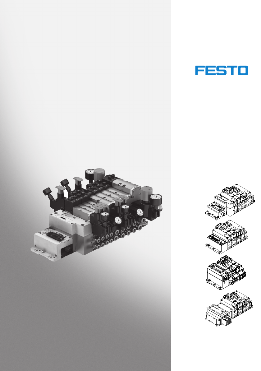
Valve terminal V TSA / VTSA-F
Description of
VTSA... pneumatics
Valve terminal with
VTSA pneumatics
Type VTSA-44-FB
Type VTSA-44-MP...
Type VTSA-44-ASI
Type VTSA-FB-03E...
Type
VTSA-F-45-FB…
Type VTSA-F-45-MP
Type VTSA-F-45-ASI
Description
538923
en 1202g
[756742]
Page 2

Page 3

Contents and general instructions
Original de.......................................
Version en 1202g..................................
Designation P.BE-VTSA-44-EN........................
Order no. 538923..................................
© (Festo AG & Co. KG, D-73726 Esslingen, 2012)
Internet: http://www.festo.com
E-Mail: [email protected]
Reproduction, distribution or sale of this document or
communication of its contents to others without express
authorization is prohibited. Offenders will be liable for
damages. All rights reserved in the event that a patent,
utility model or design patent is registered.
Festo P.BE-VTSA-44-EN en 1202g
I
Page 4

Contents and general instructions
CAGE CLAMP
®
is a registered trademark of the respective owner in certain
countries.
II
Festo P.BE-VTSA-44-EN en 1202g
Page 5

Contents and general instructions
Intended use VII..........................................................
Range of application and certifications VII.....................................
Target group VIII..........................................................
Service VIII...............................................................
Notesonthisdescription IX................................................
Important user instructions X..............................................
1. Overview of components 1-1........................................
1.1 The VTSA... valve terminal 1-4........................................
1.2 Pneumatic components, width 18 ... 52 mm 1-7.........................
1.2.1 Main and additional supply 1-9...............................
1.2.2 Valves 1-10.................................................
1.2.3 Manifold sub-bases 1-13......................................
1.2.4 Pilot control 1-13............................................
1.2.5 Pressure zone separation 1-17.................................
1.2.6 Vertical stacking 1-18........................................
1.2.7 pressure regulator plates 1-22.................................
1.2.8 Components for protective functions 1-28........................
1.2.9 Manifold sub-base VABF-S4-…-S 1-32...........................
1.3 Pneumatic components, width 65 mm 1-33..............................
1.3.1 Valves 1-34.................................................
1.3.2 Manifold sub-bases 1-35......................................
1.3.3 Pilot control 1-36............................................
1.3.4 Vertical stacking 1-36........................................
1.4 Connection and control elements of the pneu. components,
width 18 ... 52 mm 1-38..............................................
1.5 Connection, display and operating elements of the pneu. Components,
width 65 mm 1-42...................................................
1.6 Electrical components 1-44...........................................
1.6.1 VTSA... valve terminal with fieldbus 1-44.........................
1.6.2 VTSA... valve terminal with multi-pin 1-46........................
1.7 Connection and display components of the electrical components 1-49.......
Festo P.BE-VTSA-44-EN en 1202g
III
Page 6

Contents and general instructions
2. Mounting 2-1.....................................................
2.1 General instructions on assembly and dismantling 2-4....................
2.2 Mounting variants 2-5..............................................
2.2.1 Mounting/dismounting on H-rails 2-6..........................
2.2.2 Mounting/dismounting on walls 2-10...........................
2.3 Mounting/dismounting the optional inscription label holder,
width 18 ... 52 mm 2-16..............................................
2.4 Mounting/dismounting the optional manual override cover caps,
width 18 ... 52 mm 2-17..............................................
3. Installation 3-1...................................................
3.1 Compressed air preparation 3-4......................................
3.1.1 Operation with unlubricated compressed air 3-4.................
3.1.2 Operation with lubricated compressed air 3-4....................
3.2 General notes on connecting the tubing 3-7.............................
3.2.1 Installing the tubing 3-8.....................................
3.3 Connecting the VTSA... valve terminal 3-12..............................
3.4 Pilot control, width 18 ... 52 mm 3-12...................................
3.4.1 Venting pilot exhaust air 3-12..................................
3.4.2 Pilot air supply 3-13..........................................
3.5 Pilot control, width 65 mm 3-19........................................
3.5.1 Pilot air supply 3-19..........................................
3.6 Pressure zone separation, width 18 ... 52 mm 3-23........................
3.7 Pressure zone separation, width 65 mm 3-26.............................
3.8 Reversibly operated VTSA... valve terminal 3-27..........................
3.8.1 Operating the VTSA... valve terminal with reversible valves 3-28......
3.8.2 Operating the VTSA... valve terminal with reversible pressure
regulating valves 3-29........................................
3.8.3 Setting the pressure regulating valve 3-30.......................
3.9 Vacuum / low-pressure operation: 3-36.................................
3.10 Connecting the pneumatic lines 3-38...................................
3.11 Connecting the electric cables 3-49.....................................
3.12 Address assignment of the valves 3-53..................................
IV
Festo P.BE-VTSA-44-EN en 1202g
Page 7

Contents and general instructions
4. Commissioning 4-1................................................
4.1 General notes 4-4..................................................
4.1.1 Prior to commissioning 4-4...................................
4.1.2 Pressure build-up in the overall supply 4-4......................
4.2 Manual override (MO) 4-6...........................................
4.2.1 Manual override, width 18 … 52 mm 4-7........................
4.2.2 Manual override, width 65 mm 4-8.............................
4.3 Checking the valves and the valve/actuator combination 4-10...............
4.4 LED display of the valves 4-15.........................................
4.4.1 Valves, width 18 … 52 mm 4-15................................
4.4.2 Valves, widths 65 mm 4-16....................................
4.5 Fault finding 4-17...................................................
4.5.1 Impairments of function 4-17..................................
4.5.2 Operating states of the pneumatic system 4-18...................
5. Conversion and maintenance 5-1.....................................
5.1 General preventive action 5-4........................................
5.2 Dismantling the valve terminal 5-5....................................
5.3 Replacing the solenoid coil fuse, width 65 mm 5-7.......................
5.4 Replacing valve terminal components 5-9..............................
5.4.1 Replacing valves or cover plates, width 18 … 52 mm 5-9...........
5.4.2 Replacing the cover plate with a valve, width 65 mm 5-11...........
5.4.3 Replacing/adding components for vertical stacking,
width 18 … 52 mm 5-13.......................................
5.4.4 Replacing/adding components for vertical stacking,
widths 65 mm 5-18..........................................
5.4.5 Replacing the exhaust plate or exhaust port cover,
widths 18 … 52 mm 5-19......................................
5.4.6 Replacing the manifold sub-base, pneumatic supply plate or
right end plate, widths 18 … 52 mm 5-19.........................
5.4.7 Replacing the manifold sub-base or right end plate,
size 65 mm 5-23.............................................
Festo P.BE-VTSA-44-EN en 1202g
V
Page 8

Contents and general instructions
5.5 Converting the VTSA... valve terminal 5-30...............................
5.5.1 Conversion, pilot exhaust air via port (12), widths 18 … 52 mm 5-30..
5.5.2 Conversion, internal or external pilot air supply,
width 18 … 52 mm 5-32.......................................
5.5.3 Conversion, internal or external pilot air supply, widths 65 mm 5-33..
5.5.4 Conversion, VTSA... valve terminal with two or more pressure zones,
width 18 … 52 mm 5-36.......................................
5.5.5 Conversion, valve terminal with 2 pressure zones, widths 65 mm 5-39.
5.5.6 Adding valve positions, widths 18 … 52 mm 5-40..................
5.5.7 Adding valve positions, widths 65 mm 5-41.......................
5.5.8 Adding a soft-start valve 5-43..................................
A. Technical appendix A-1.............................................
A.1 Technical data A-3..................................................
A.2 Accessories A-28....................................................
B. Supplementary overview of components B-1...........................
B.1 Overview of valve position components B-3.............................
B.2 Separating the VTSA... valve terminal from the CPX terminal
or FB 21 (type 03) B-15...............................................
C. Index C-1.........................................................
VI
Festo P.BE-VTSA-44-EN en 1202g
Page 9
Contents and general instructions
Intended use
The VTSA... valve terminals described in this manual are intended for fitting into a machine or automated system. The
user must at all times observe the safety regulations specified in this manual, as well as the instructions concerning
the designated use of the relevant VTSA... valve terminal. The
VTSA... valve terminals may only be used as follows:
– as intended for switching of gaseous media ( Appendix
– in original status without unauthorised modifications.
– in excellent technical condition.
If used together with additional commercially available components, such as actuators, the specified limits for pressures,
temperatures, electrical data, torques etc. must be observed.
Observe the corresponding regulations of the trade associations, German Technical Control Board (TÜV), VDE stipulations or relevant national regulations.
A “Technical data”) in an industrial environment
Only the conversions or modifications described in the
documentation supplied with the product are permitted.
Range of application and certifications
The product fulfils the requirements of EU directives and is
marked with the CE marking.
Standards and test values, which the product must comply
with and fulfill, can be found in the section “Technical data”.
The product-relevant E U directive can be found in the declaration of conformity.
Festo P.BE-VTSA-44-EN en 1202g
VII
Page 10

Contents and general instructions
Certain configurations of the product have been certified by
Underwriters Laboratories Inc. (UL) for the USA and Canada.
These configurations bear the following mark:
UL Recognized Component Mark for Canada and the United
States.
Note
Observe the following if the UL requirements are to be
complied with in your application:
– Rules for observing the UL certification can be found in
– The technical data in this documentation may show val-
the separate UL-specific documentation. The relevant
technical specifications listed there also apply here.
ues deviating from this.
Targ et g rou p
Service
VIII
This manual is directed exclusively toward technicians trained
in control and automation technology.
Please consult your local Festo repair service if you have any
technical problems.
Festo P.BE-VTSA-44-EN en 1202g
Page 11

Contents and general instructions
Notesonthisdescription
This manual contains specific information on fitting, installing,
commissioning, servicing and converting the VTSA... valve
terminal. It refers only to a description of the pneumatic components of the following valve terminal variants:
– Valve terminal with CPX terminal:
– Valve terminal with type 03 electronics:
Information on CPX modules can be found in the manual
for the relevant module. An overview is provided in the
system description of your CPX terminal, in the “DescriptionsoftheCPXterminal”table.
Information on the fieldbus connection can be found in
thetype03electronicsdescription“INTERBUSRugged
Line fibre optic cable remote bus”.
Information about the I/O modules can be found in the
type 03 “Supplementary description of the I/O modules”.
Additional information about the multi I/O modules is
included in the documentation supplied with the product.
Festo P.BE-VTSA-44-EN en 1202g
– All valve terminals with multi-pin node (Sub-D, cage
clamp, M23 round plug, M12 individual connections):
For information on the electric/electronic components see
the documentation supplied with the product.
– Valve terminal with AS-interface:
Information about the electric/electronic components is
included in the documentation supplied with the product.
IX
Page 12
Contents and general instructions
Important user instructions
Danger categories
This description includes instructions on the possible dangers
which can occur if the product is used incorrectly. These instructions are marked with a signal word (Warning, Caution,
etc.), printed on a shaded background and marked additionally with a pictogram. A distinction is made between the following danger warnings:
Warning
... means that failure to observe this instruction may result
in serious personal injury or material damage.
Caution
... means that failure to observe this instruction may result
in personal injury or material damage.
Note
... means that failure to observe this instruction may result
in material damage.
In addition, the following pictogram marks passages in the
text which describe activities with electrostatically sensitive
devices:
Electrostatically sensitive devices: Incorrect handling may
cause damage to devices.
X
Festo P.BE-VTSA-44-EN en 1202g
Page 13
Contents and general instructions
Marking special information
The following pictograms mark passages in the text which
contain special information.
Pictograms
Information:
Recommendations, tips and references to other information
sources.
Accessories:
Information about necessary or useful accessories for the
product from Festo.
Environment:
Information about environmentally friendly use of products
from Festo.
Festo P.BE-VTSA-44-EN en 1202g
Text markings
•
Bullet points indicate activities which may be carried out
in any sequence.
1. Numerals identify activities which must be carried out in
the sequence specified.
– Arrowheads indicate general lists.
XI
Page 14
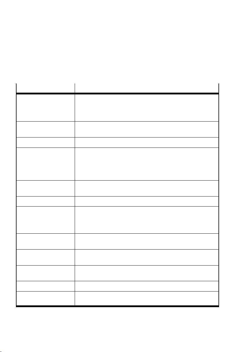
Contents and general instructions
The following product-specific terms and abbreviations are
usedinthisdescription:
Term/abbreviation
90° connection plate – Reversing unit (90°)
Basic components – Pneumatic interface, pneu. manifold sub-base and pneu. Supply
Blanking plate – Cover for a non-assigned valve location on the manifold sub-base
Components – Common term for pneumatic interface, pneumatic manifold sub-
CPX modules – Common term for the various modules which can be incorporated
CPX terminal – Modular electric terminal type 50
End plate – Extreme right-hand plate on the valve terminal VTSA or VTSA-F with
Exhaust plate – Cover of the pneumatic supply plate
Exhaust port cover – Cover of the pneumatic supply plate
Meaning
– With work connections (2) and (4)
The 90°-connection plate is attached to the connection side of the
manifold sub-base.
plate
base or pneumatic Supply plate, end plate, 90°-connection plate,
exhaust plate, exhaust port cover, vertical supply plate, pressure
regulator plate, flow control plate, soft-start valve, directional control valve or cover plate
into a CPX terminal
holes for wall mounting
– Extreme left-hand plate of the CPX terminal with holes for wall
mounting
– With separate exhaust connections (3) and (5)
– Common exhaust port (3/5)
FB 21, type 03 – INTERBUS “Rugged Line” optic fibre cable remote bus fieldbus
I/O – Input/output modules
Intermediate solenoid
plate
XII
connection
– Plate with solenoid coils, air ducts and electric plug connectors to
ISO 5599/2
Festo P.BE-VTSA-44-EN en 1202g
Page 15
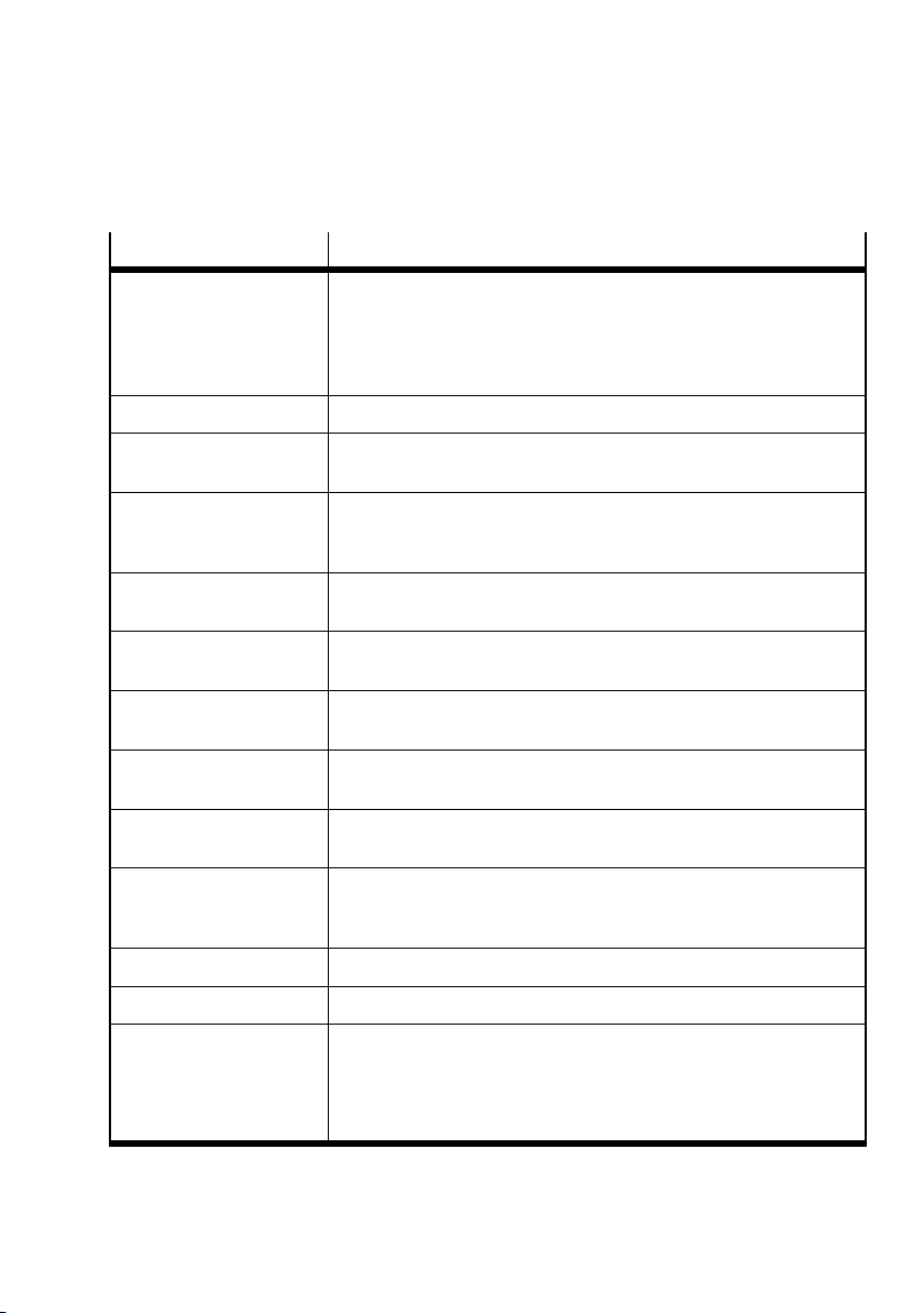
Contents and general instructions
Term/abbreviation Meaning
Manifold sub-base – Plate with electrical interlinking
MO – Manual override
Multi-pin node
M23 round plug
Multi-pin node IC – Interface with individual electric connections via which the valve
Multi-pin node, cage clamp – Interface with terminal strip via which all valve solenoid coils are
Multi-pin node, Sub-D – Interface with electric Sub-D multi-pin plug connection via which all
Pneumatic interface – Interface between the modular electric peripherals of the CPX ter-
Pneumatic module – Module consisting of manifold block, angled sub-base, valve or
Pneumatic supply plate – Plate within the horizontal stacking for supplying pressure to a
Selector end plate – Rightmost panel of the VTSA... valve terminal with coding cap (for
– With two valve p ositions for 18 mm and 26 mm widths
– With one valve position for 4 2 mm (ISO 1), 52 mm (ISO 2) and 65
mm (ISO 3) widths
– Per valve position with working lines (2) and (4).
– Interface with electric M23 round plug via which all solenoid coils
are connected centrally
solenoid coils are connected individually
– IC = Individual Connector
centrally connected
solenoid coils are connected centrally
minal or the FB21 (type 03) and the VTSA... pneumatics
cover plate, or components for vertical stacking
pressure zone
selection of the pilot variant and disposal of pilot exhaust air)
– with pneumatic ports (12) and (14)
Tubing connections – Connecting the supply lines (tubing) to the valve terminal
Valve – Solenoid valve with monostable, impulse or mid-position valve
Valve terminal VTSA... – Valve terminal VTSA (type 44) or VTSA-F (type 45)
– With CPX terminal
– With FB 21 (type 03)
– AS-interface
– Or with multi-pin node (Sub-D, cage clamp, M23 round plug or IC).
Festo P.BE-VTSA-44-EN en 1202g
XIII
Page 16
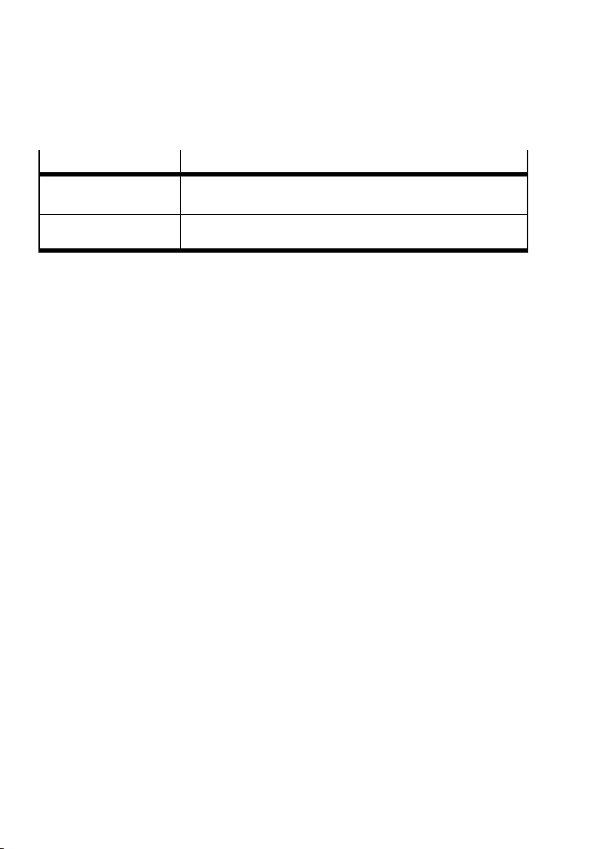
Contents and general instructions
Term/abbreviation Meaning
Vertical pressure shut-off
plate
Vertical pressure supply
plate
– Plate on a valve location for isolating the valve pressure supply
– Plate on a valve position for individual compressed air supply
Tab. 0/1: Product-specific terms and abbreviations
XIV
Festo P.BE-VTSA-44-EN en 1202g
Page 17

Overview of components
Chapter 1
Overview of components
Festo P.BE-VTSA-44-EN en 1202g
1-1
Page 18

1. Overview of components
Contents
1. Overview of components 1-1........................................
1.1 The VTSA... valve terminal 1-4........................................
1.2 Pneumatic components, width 18 ... 52 mm 1-7.........................
1.2.1 Main and additional supply 1-9...............................
1.2.2 Valves 1-10.................................................
1.2.3 Manifold sub-bases 1-13......................................
1.2.4 Pilot control 1-13............................................
1.2.5 Pressure zone separation 1-17.................................
1.2.6 Vertical stacking 1-18........................................
1.2.7 pressure regulator plates 1-22.................................
1.2.8 Components for protective functions 1-28........................
1.2.9 Manifold sub-base VABF-S4-…-S 1-32...........................
1.3 Pneumatic components, width 65 mm 1-33..............................
1.3.1 Valves 1-34.................................................
1.3.2 Manifold sub-bases 1-35......................................
1.3.3 Pilot control 1-36............................................
1.3.4 Vertical stacking 1-36........................................
1.4 Connection and control elements of the pneu. components,
width 18 ... 52 mm 1-38..............................................
1.5 Connection, display and operating elements of the pneu.
Components, width 65 mm 1-42.......................................
1.6 Electrical components 1-44...........................................
1.6.1 VTSA... valve terminal with fieldbus 1-44.........................
1.6.2 VTSA... valve terminal with multi-pin 1-46........................
1.7 Connection and display components of the electrical components 1-49.......
1-2
Festo P.BE-VTSA-44-EN en 1202g
Page 19

1. Overview of components
Contents of this chapter This chapter provides the following information on the
VTSA... valve terminal:
– The maximum number of valve positions
– The connection variants and components of the valve
terminal
– The labelling of the pneumatic components
– Connection, display and operating elements
More information Information on the modules of the CPX terminal can be
found in the CPX system description.
Information about the type 03 electronics modules is included in the relevant type 03 electronics descriptions.
Information on the electronics of the VTSA... valve terminal
with multi-pin node can be found in the corresponding package insert.
Festo P.BE-VTSA-44-EN en 1202g
Information on the electronics of the VTSA... valve terminal
with AS interface can be found in the corresponding package insert.
1-3
Page 20

1. Overview of components
1.1 The VTSA... valve terminal
Festo assists you in solving your automation tasks at machine
level with VTSA... valve terminals. The modular structure of
the valve terminal enables you to match it optimally in your
machine or system.
The valve terminal pneumatics establish the following connections:
– Common ducts for supply and exhaust air
– Electric signals from all solenoid coils
The working lines (2) and (4) are provided for each valve position on the individual manifold sub-bases. The valves are
supplied with compressed air (operating pressure and pilot
pressure) via the common channels and connections in the
pneumatic supply plates. The exhaust air (from the valves
and the pilot exhaust) is also exhausted via these common
channels and connections.
Dependent on its width, the valve terminal can be supplemented by additional pneumatic supply plates, such as to supply
pressure zones.
The function range at each valve position can be extended by
means of additional vertical stacking components, e.g. exhaust air flow control or pressure regulation.
Valve widths The valve terminal is available with valves in the following
widths:
1-4
Festo P.BE-VTSA-44-EN en 1202g
Page 21
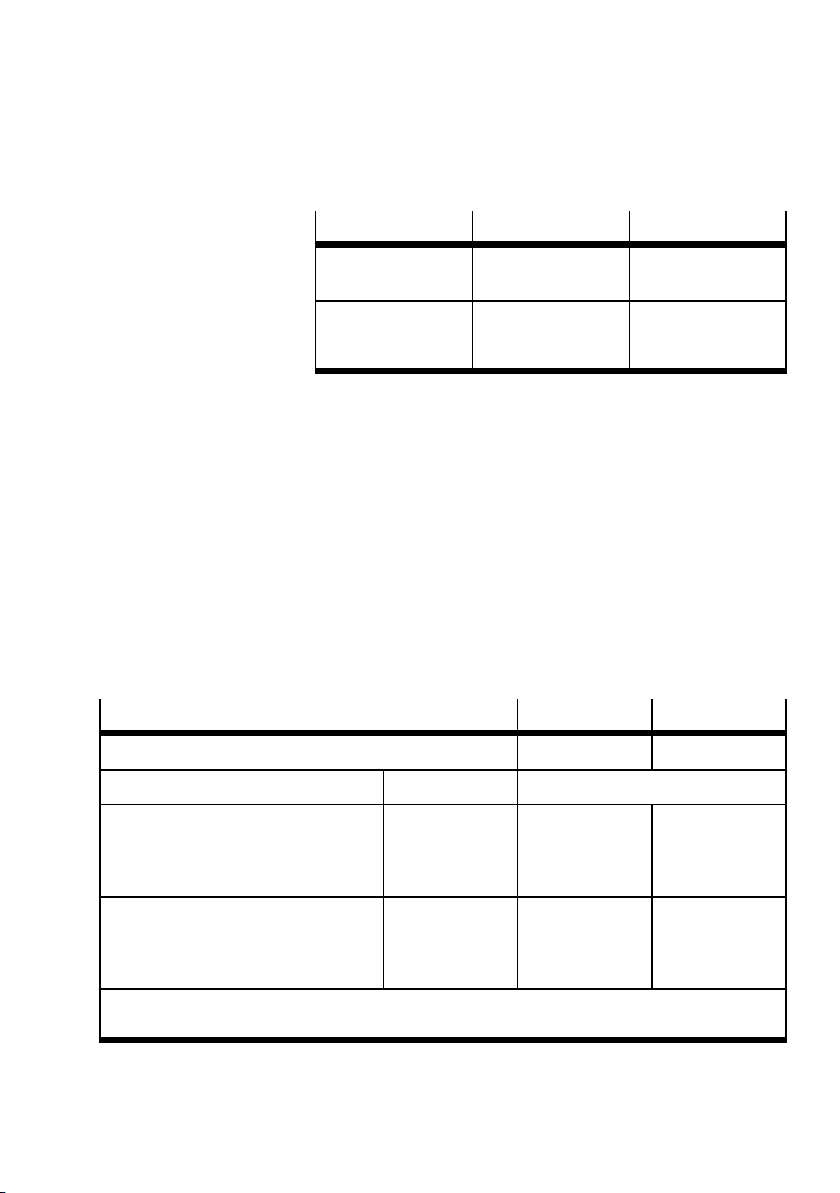
1. Overview of components
Width Size Standard
18 mm
26 mm
42 mm
52 mm
65 mm
02
01
1
2
3
ISO 15407-2
ISO 5599-2
Tab. 1/1: Widths
For the combination of widths 18 ... 52 mm on the
valve terminal, no adapter plate is required.
The 65 mm width (ISO 3) is an adaptation of the pneumatics
of valve terminal type 04-B. In order to combine these widths
with smaller widths, adapter type VABA-S6-7-S2-3-... is required.
The VTSA... valve terminal is available with the following number of valve positions depending on the manifold sub-bases
used and the electrical connection variant.
VTSA with:
Max. number of controllable solenoid coils 32 26
Manifold sub-base type Width [mm] Number of valve positions
1 controllable coil per valve position
– VABV...-2T1
– VABV...-T1
–VIGM-04-D-3
1)
18 or 26
42 or 52
65
CPX terminal FB 21, type 03
2, 4, 6 ... 32
1, 2, 3 ... 32
1, 2, 3 ... 26
2, 4, 6 ... 26
1, 2, 3 ... 26
1, 2, 3 ... 26
1)
2 controllable coils per valve position
– VABV...-2T2
– VABV...-T2
–VIGI-04-D-3
1) The maximum number of valve positions does not apply in the case of mixed components of a
valve terminal with manifold sub-bases T1 and T2 or VIGM and VIGI.
2)
18 or 26
42 or 52
65
2, 4, 6 ... 16
1, 2, 3 ... 16
1, 2, 3 ... 13
2, 4, 6 ... 12
1, 2, 3 ... 13
1, 2, 3 ... 13
Tab. 1/2: Number of valve positions for VTSA... with CPX terminal or FB21, type 03
Festo P.BE-VTSA-44-EN en 1202g
1-5
Page 22
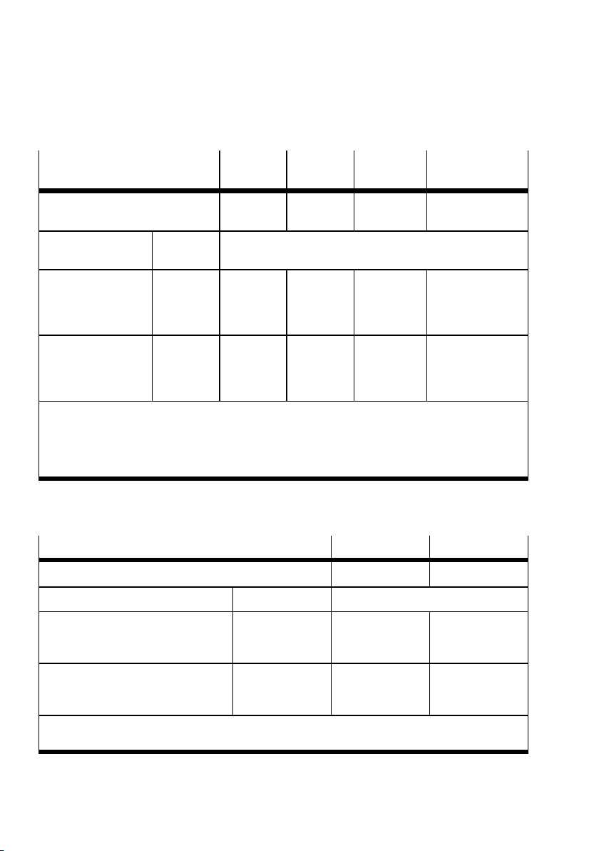
1. Overview of components
VTSA with multi-pin plug
connection
Maximum number of solenoid coils
which can be actuated
Manifold sub-base
type
1 controllable coil
per valve position
– VABV...-2T1
– VABV...-T1
2 controllable coils
per valve position
– VABV...-2T2
– VABV...-T2
1) Multi-pin IC with 10 or 6 individual connections. 2 solenoid coils can be connected for each individual connection.
2) Specification in parentheses (12) or (6) for IC with 6 individual connections.
3) The maximum number of valve positions does not apply in the case of mixed components of a
valve terminal with manifold sub-bases T1 and T2.
Width [mm] Number of valve positions
18 or 26
42 or 52
18 or 26
42 or 52
Sub-D Cage
clamp
32 32 16 20 (12)
2, 4, 6 ... 32
1, 2, 3 ... 32
2, 4, 6 ... 16
1, 2, 3 ... 16
2, 4, 6 ... 32
1, 2, 3 ... 32
2, 4, 6 ... 16
1, 2, 3 ... 16
M23 round
plug
3)
2, 4, 6 ... 16
1, 2, 3 ... 16
2, 4, 6 ... 8
1, 2, 3 ... 8
Individual connection (IC)
2, 4, 6 ... 20 (12)
1, 2, 3 ... 20 (12)
2, 4, 6 ... 10 (6)
1, 2, 3 ... 10 (6)
Tab. 1/3: Number of valve positions for VTSA... with multi-pin plug connection
VTSA with AS interface type
VTSA-4E4A-Z VTSA-8E8A-Z
1) 2)
Maximum number of solenoid coils which can be actuated 4 8
Type of manifold sub-bases Width [mm] Number of valve positions
1 controllable coil per valve position
– VABV...-2T1
– VABV...-T1
2 controllable coils per valve position
– VABV...-2T2
– VABV...-T2
1) The maximum number of valve positions does not apply in the case of mixed components of a
valve terminal with manifold sub-bases T1 and T2.
18 or 26
42 or 52
18 or 26
42 or 52
2or4
1, 2, 3 ... 4
2
1or2
1)
2, 4, 6 ... 8
1, 2, 3 ... 8
2or4
1, 2, 3 ... 4
Tab. 1/4: Number of valve positions for VTSA... with AS-interface
1-6
Festo P.BE-VTSA-44-EN en 1202g
Page 23
1. Overview of components
1.2 Pneumatic components, width 18 ... 52 mm
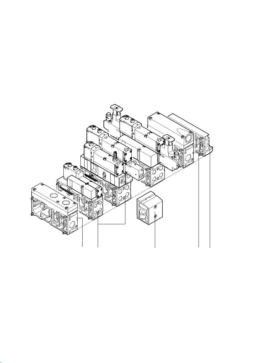
The VTSA valve terminal consists of pneumatic and electric
components: The essential components of width 18 ... 52 mm
are shown in Fig. 1/1 and Fig. 1/2.
2
1
right end plate
2
Pneumatic supply plates
(optional)
Fig. 1/1: Pneumatic base components of the VTSA... valve terminal (1st level)
Festo P.BE-VTSA-44-EN en 1202g
3
90°-connection plate (optional)
4
Manifold sub-base
234
1
1-7
Page 24
1. Overview of components
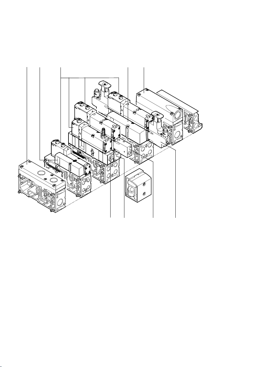
1
1
2
23 4
Exhaust plate
Blanking plate for valve position
(optional)
8
2
7
5
Pressure regulator plate (optional)
6
Vertical pressure shut-off plate
(optional)
6
5
3
Valves
4
Exhaust port cover
Fig. 1/2: Pneumatic base components of the VTSA... valve terminal (2nd level)
1-8
7
Vertical pressure supply plate
(optional)
8
Flow control plate (optional)
Festo P.BE-VTSA-44-EN en 1202g
Page 25
1. Overview of components
1.2.1 Main and additional supply
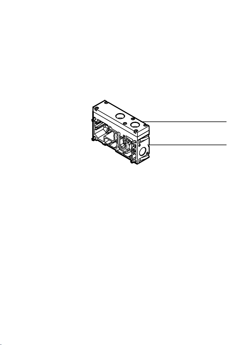
The main supply of the valve terminal with operating pressure
can be made via a pneumatic supply plate ( Fig. 1/3) or via
the right end plate with axial supply ports ( Tab. 1/7).
1
Exhaust plate for
ducted exhaust
air
2
Supply plate
Fig. 1/3: Pneumatic supply plate
1
2
Festo P.BE-VTSA-44-EN en 1202g
The pneumatic supply plate can also be used for additional
supply. This is necessary, for example, if the valve terminal is
operated with several pressure zones or if many valves simultaneously are switched to flow or exhausted on the valve terminal.
1-9
Page 26
1. Overview of components
1.2.2 Valves
The VTSA... valve terminal can be equipped with the following
valves:
– 5/2-way valves, (monostable or bistable)
– 5/3-way mid-position valves
– 2x2/2-way valves
– 2x3/2-way valves
– reversible 2x3/2-way valves
Dependent on the valve type, the VTSA-… can be operated as
follows:
– Standard operation (- 0.9 … 10 bar)
1-10
– Reversible operation (- 0.9 … 10 bar).
The compressed air supply for reversible operation of the
VTSA… is provided via ports (3) and (5).
Theexhaustprocedureiseffectedviaport(1)
( also see section 3.8 and 3.8.1)
All 5/2-way valves and 5/3-way mid-position valves can be
used in all operating modes.
Festo P.BE-VTSA-44-EN en 1202g
Page 27
1. Overview of components
Identifying the valves The valves are labelled with an ident. code. You will find the
ident. code on the top of the valves.
Ident.
Valves
code
5/2-way valves:
J 5/2-way valve, double solenoid
D 5/2-way valve, bistable with dominant signal
M Monostable 5/2-way valve, pneumatic spring return
O Monostable 5/2-way valve, mechanical spring return
SO
SQ
SP
SN
5/3-way valves:
G 5/3-way valve, normally closed
E 5/3-way valve, normally exhausted
SA 5/3-way valve, normally exhausted, switching position 14 latching
B 5/3-way valve, normally open
SB 5/3-way valve, normallyopen from 1 > 2, switching position 14 latching
Monostable 5/2-way valve with piston position sensing via inductive sensor, mechanical
spring return, se nsor with PNP or NPN output
Control block with safety function:
Two 5/2-way valves with piston position sensing via inductive sensor, mechanical spring
return, special vertical stacking plate for the interconnection of both valves, sensor with
PNP or NPN output, individual connection plug type C
3/2-way valves:
K Two monostable 3/2-way valves, normally closed
H Two monostable 3/2-way valves, controlside 14 normally open, control side 12 normally
closed
N Two monostable 3/2-way valves, normally open
Reversible 3/2-way valves:
P Two monostable reversible 3/2-way valves, normally open
Festo P.BE-VTSA-44-EN en 1202g
1-11
Page 28
1. Overview of components
Ident.
Valves
code
Q Two monostable reversible 3/2-way valves, normally closed
R Two monostable reversible 3/2-way valves, control side 14 normally open, control side 12
2/2-way valves:
VC Two monostable 2/2-wayvalves, normally closed
VV Two 2/2-way valves, normally closed,
normally closed
supplied with operating pressure via ports (3) or (5).
Pneumatic spring supplied via port (1)
This valve can be used for vacuum opera tion with ejector pulse or for dual-pressure operation (
pressure operation, as well as in Appendix B1 Valve overview Tab. B/5).
instructions in the sections 3.6 Pressure zone separation, 3.9 Vacuum/low
Tab. 1/5: Identification of the valve function in the type code
5/2-way valves with piston position sensing
The monostable 5/2-way valves with ID code SO or SQ (width
26 mm) have a piston position sensing. An inductive sensor
(N/C contact) monitors the neutral position of the piston
spool. The sensor has a PNP or an NPN output. The valve is
actuated via a multi-pin or fieldbus connection.
1-12
5/3-way valve with extended function
The 5/3-way valves with ident. code SA or SB have a signalstoring function in switching position 14. If there is no longer
a signal on coil 14, the switching position 14 remains as is,
since there is no spring return on control side 12. Switching
position 12 is non-latching due to the mechanical spring
force.
Further information on the valves can be found in Appendix B.
Festo P.BE-VTSA-44-EN en 1202g
Page 29
1. Overview of components
1.2.3 Manifold sub-bases
The number of electrically controllable valve positions depends on the manifold sub-bases and the electrical connection used ( Tab. 1/ 2 .. . Tab. 1/4).
If only manifold sub-bases that support the control of two
solenoid coils per valve position are used, any type of valve
can be placed in any valve position.
If, on the other hand, only manifold sub-bases that control
only one solenoid coil per valve position are used, the valve
terminal can only be equipped with monostable 5/2-way
valves(ident.codeM,O,SOorSQ).
Identification features
Type code VABV-S4-...T1 or
Identifier code on the type plate
of the manifold sub-base
Colour of the solenoid coil
contact
Manifold sub-bases, width 18 ... 52 mm
for actuating one solenoid
coil per valve position
VABV-S2-...T1
Black dot —
Red Black
for actuating two solenoid
coils per valve position
VABV-S4-...T2 or
VABV-S2-...T2
Tab. 1/6: Identification of the manifold sub-bases, width 18 ... 52 mm
1.2.4 Pilot control
The pilot control of the solenoid coils is supplied with internal
or external pilot air. This pilot air is made available for the
entire valve terminal (also across pressure zones) through the
soft-start valve or the various right end plate variants. The
following applies:
Festo P.BE-VTSA-44-EN en 1202g
1-13
Page 30

1. Overview of components
– The valve terminal is always supplied with internal pilot
air through the soft-start valve
– Through the corresponding right end plate variants, you
can choose whether the valve terminal should be supplied
with internal or external pilot air.
1-14
Festo P.BE-VTSA-44-EN en 1202g
Page 31

1. Overview of components
There are two groups of end plates with the VTSA... valve
terminal.
– For end plates with axial ports, the type of pilot air supply
(internal or external) is determined by the design.
– The following can be selected for the selector-end plate:
– the type of pilot air supply (internal or external)
– the manner of venting the pilot exhaust air (via duct
(12) or at the valve)
You can ascertain the end plate with which your VTSA... valve
terminal is fitted by means of the following table. Conversion
between internal and external pilot air supply is described in
section 5.5.2.
Festo P.BE-VTSA-44-EN en 1202g
1-15
Page 32
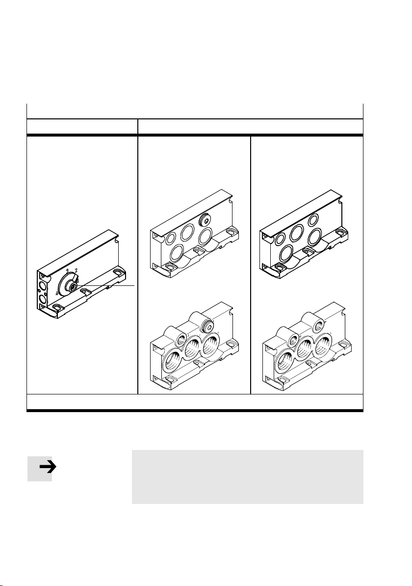
1. Overview of components
Variants of the right end plate
Selector end plate End plates with axial supply connections
Type VABE-...RZ-...B1.
End plate for operation of the
valve terminal with internal or
external pilot air supply and selection of the manner for venting the pilot exhaust air. Selection via setting of the selector
1)
plate 2
Type VABE-...R-...
End plate for operating the valve
terminal with internal pilot air
1)
supply.
Size 1:
Type VABE-...RZ-...
End plate for operating the
valve terminal with an external
pilot air supply.
Size 1:
1)
2
Size 2:
1) Instructions on adjusting the selector plate or on fitting the end plates (section 3.4.2)
Tab. 1/7: Variants of the right end plate for widths 18 ... 52mm
Size 2:
1-16
Note
Instructions for combining the soft-start valve and the right
end plate can be found in the assembly instructions
VABV-S6-1Q-...
Festo P.BE-VTSA-44-EN en 1202g
Page 33
1. Overview of components
1.2.5 Pressure zone separation
Using special seal plates, you can divide the VTSA… valve
terminal into pressure zones ( 3.8). The following ducts can
be separated with the seal plates:
– Supply duct (1) only
– Supply duct (1) and exhaust ducts (3) and (5)
– Exhaust ducts (3) and (5) only
In the VTSA... valve terminal, the pilot control for the valves is
supplied with pilot air centrally via the right end plate or via
the soft-start valve. A pressure zone separation of pilot ducts
(12) and (14) is therefore not possible.
You can ascertain the number of pressure zones with which
your valve terminal is equipped by the marking on the sealin g
plate ( Fig.).
Festo P.BE-VTSA-44-EN en 1202g
1-17
Page 34
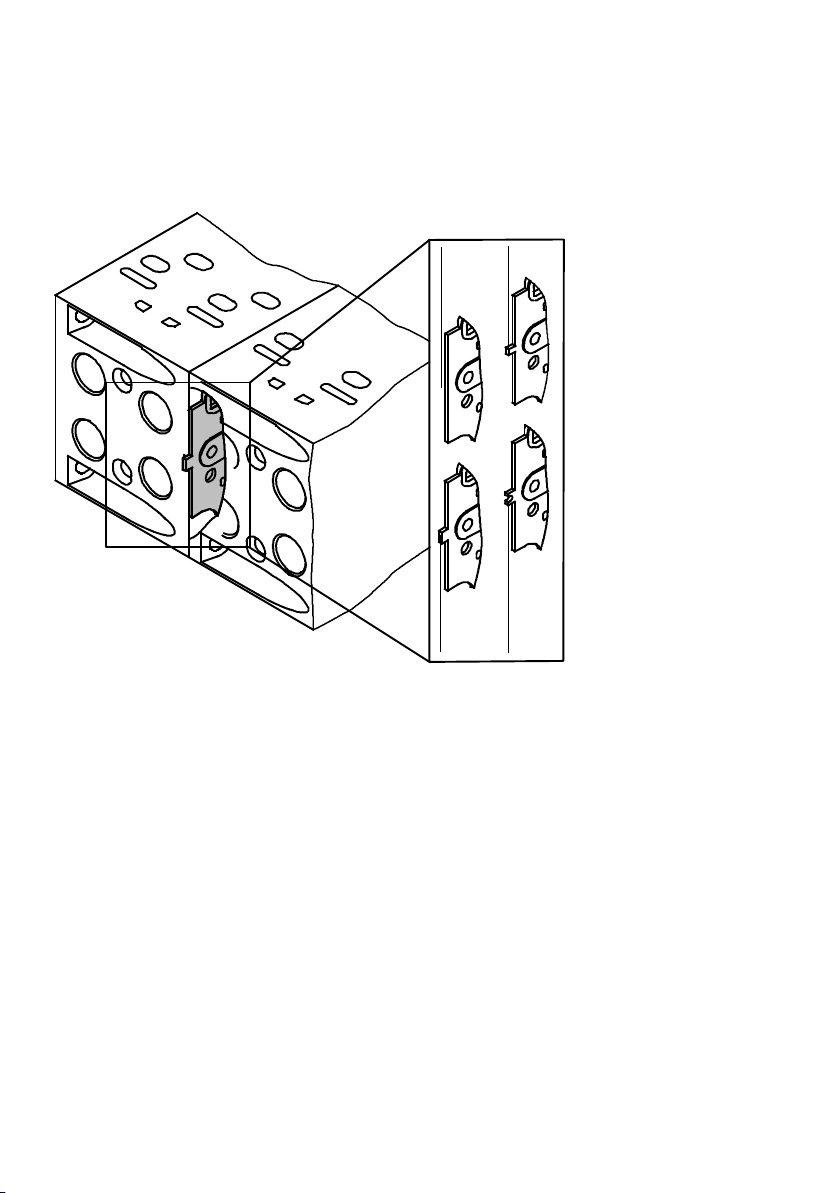
1. Overview of components
1
All channels open if not marked
2
Duct (1) closed
Fig. 1/4: Identifying the seal plates
1
4
3
Ducts (3) and (5) closed
4
Ducts (1), (3) and (5) closed
2
3
1.2.6 Vertical stacking
1-18
You can mount further pneumatic components in each location between the manifold sub-base and the valve. This vertical stacking will enable you to implement certain additional
effects as desired.
Tab. 1/8 shows the basic design and possible components of
vertical stacking.
Festo P.BE-VTSA-44-EN en 1202g
Page 35
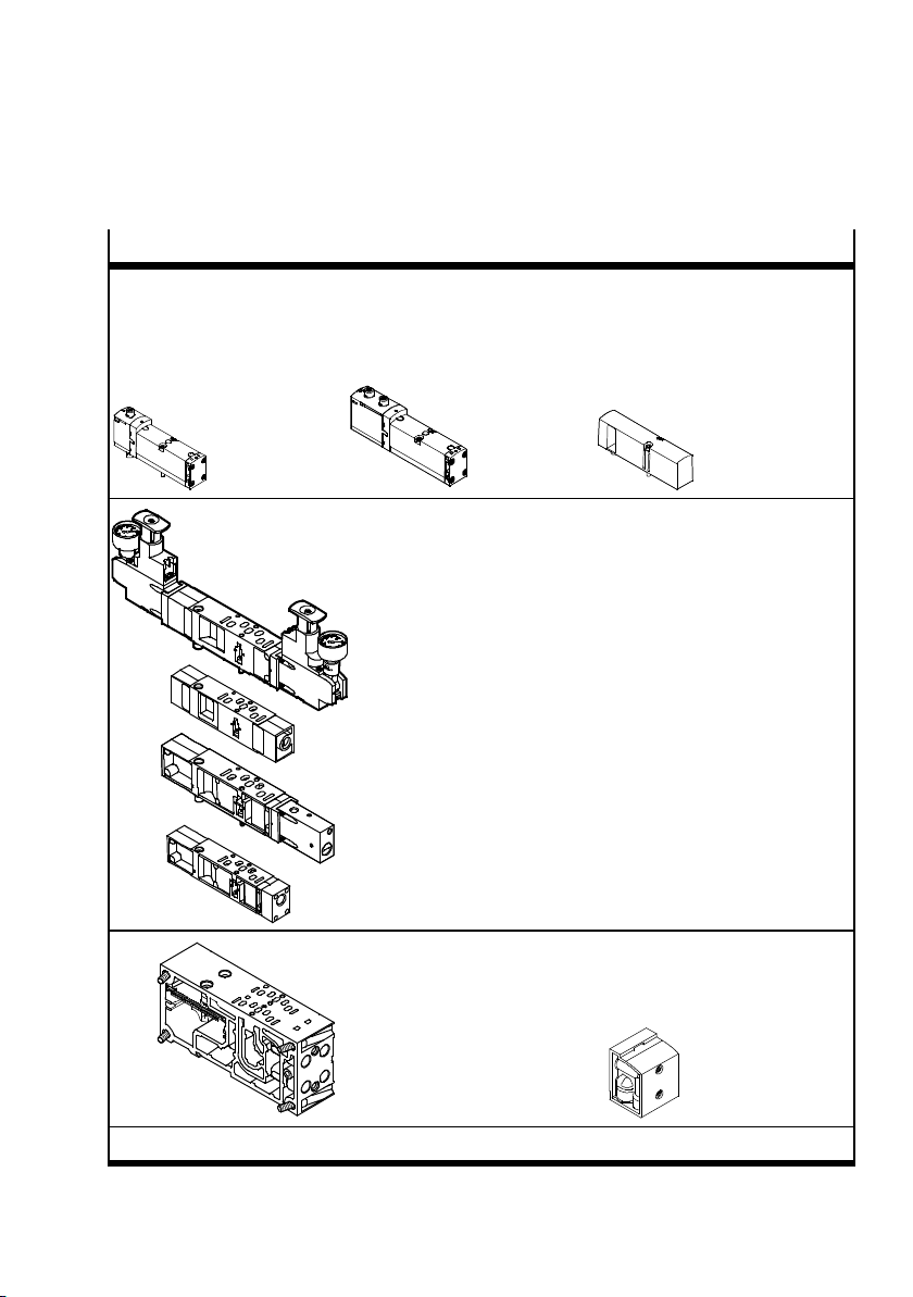
1. Overview of components
y
p
1
)
Components (width 18 ... 52 mm)
Monostable 5/2-wa
valves
Alternatively:
Valve with two monostable
2/2-way valves, 3/2-wayvalves
or one bistable 5/2-way valve or
one 5/3-way valve
Vertical stacking, o
Pressure regulator plate type: VABF-S4...R... or VABF-S2...R... (with
or without pressure gauge)
Flow control plate type VABF-S4...F1B1... or VABF-S2...F1B1...,
Pressure shut-off plate type: VABF-S4...L1D1... or VABF-S2...L1D1...
Vertical pressure supply plate type: VABF-S4...P1A3... or
VABF-S2...P1A3...
tional components:
Alternatively:
Cover plate, for sealing an unused
valve position
type: VABB-S4...WT... or
VABB-S2...WT...
Manifold sub-base
type VABV...T1 or
type VABV...T2
1) Instructions on installing the vertical stacking components (chapter 3)
Optional: 90°-connection plate
type VABF...A1G2... Working
connections (2) and (4)
turned 90°
Tab. 1/8: Components of the pneumatic module of the VTSA... valve terminal
Festo P.BE-VTSA-44-EN en 1202g
1-19
Page 36

1. Overview of components
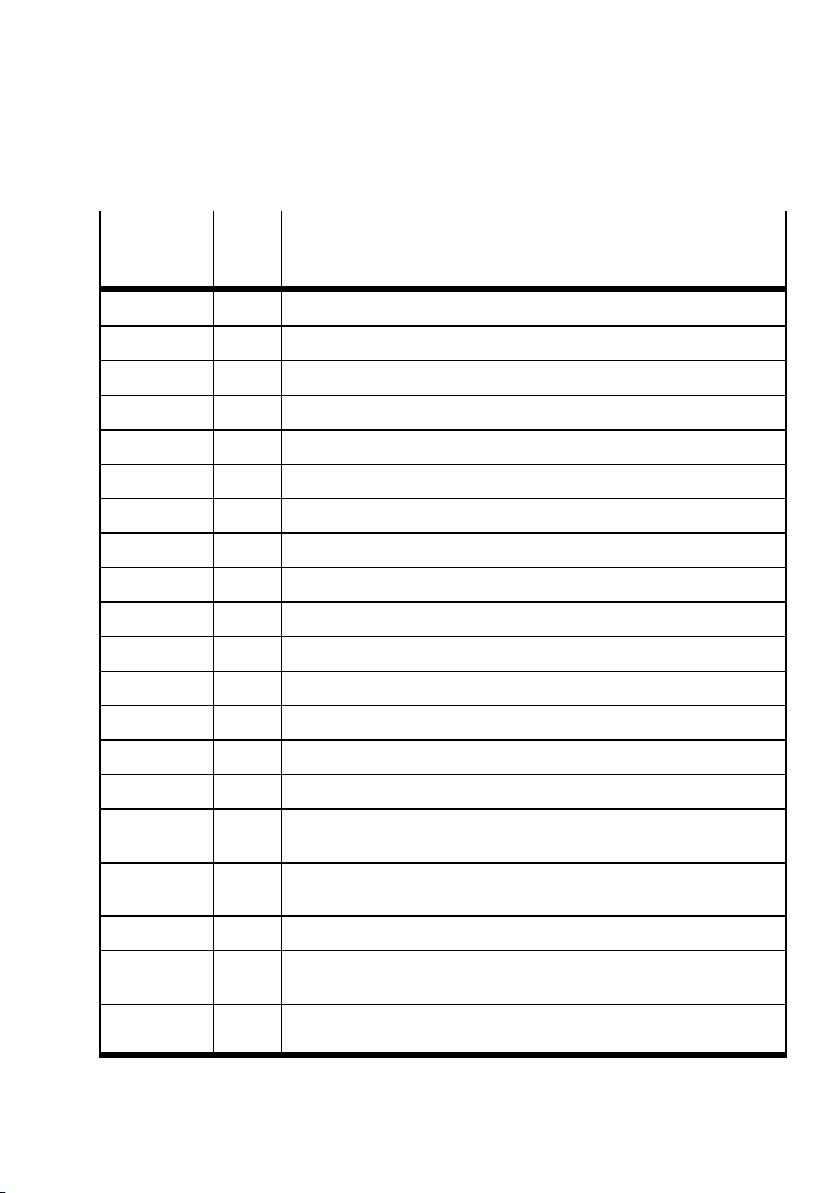
The vertical stacking components on the VTSA... valve terminal are marked by type codes. The code is printed on the side
of the component. An identifier within the type code indicates
the function of the component; for example, in the type code
VABF-S4-1R1C2-C-10:
– Identification R1 means the component is a P-pressure
regulator
– Identification 10 means the control range of the pressure
regulator extends to 10 bar
In the sales documentation and in the Festo Configurator, the
components are marked with an ID code.
You can identify the vertical stacking components with the aid
of the following table. Not every pressure regulator function
is available for all widths.
1-20
Festo P.BE-VTSA-44-EN en 1202g
Page 37
1. Overview of components
Identification in
Ident.
code
Vertical stacking component
type code
R1-...-6 ZF P-pressure regulator plate for port (1)
R1-...-10 ZA, ZAY P-pressure regulator plate for port (1)
R2-...-6 ZH B-pressure regulator plate for port (2)
R2-...-10 ZC, ZCY B-pressure regulator plate for port (2),
R3-...-6 ZG A-pressure regulator plate for port (4)
R3-...-10 ZB A-pressure regulator plate for port (4)
R4-...-6 ZI, ZIY AB-pressure regulator plate for ports (2) and (4)
R4-...-10 ZD AB-pressure regulator plate for ports (2) and (4)
R5-...-6 ZJ Reversible AB-pressure regulator plate for ports (2) and (4)
R5-...-10 ZE, ZEY Reversible AB-pressure regulator plate for ports (2) and (4)
R6-...-6 ZM Reversible B-pressure regulator plate for port (2)
R6-...-10 ZK Reversible B-pressure regulator plate for port (2)
R7-...-6 ZN, ZNY Reversible A-pressure regulator plate for port (4)
R7-...-10 ZL Reversible A-pressure regulator plate for port (4)
F1B1 X Flow control plate for restricting the exhaust in ducts (3) and (5)
P1A3 ZU Vertical pressure supply plate for providing an individual operating pres-
sure for a valve position
L1D1 ZT Vertical pressure shut-off plate for cutting off the individual operating
pressure for a valve position
ZO Intermediate plate for disconnectable pilot air
WL Mechanical pressure switch for monitoring the disconnectable pilot air
supply
WH Electronic pressure switch f or monitoring the disconnectable pilot air
supply
Tab. 1/9: Identification of the vertical stacking components
Festo P.BE-VTSA-44-EN en 1202g
1-21
Page 38
1. Overview of components
The circuit symbols for the vertical stacking components can
be found in Appendix B, Tab. B/7 ... Tab. B/9.
1.2.7 pressure regulator plates
Mode of operation To influence the force of connected actuators, a pressure reg-
ulator plate with adjustable pressure regulating valve can be
built in between the manifold sub-base and valve.
This pressure regulator maintains an essentially constant
output pressure (secondary side) independent of supply
pressure (primary side) and air consumption.
The following descriptions of the pressure regulator functions
are provided using the example of the pressure regulator
type VABF-S4-1..C2-C-... (VTSA pressure regulator of width
18 ... 52 mm).
P-pressure regulator (identifier R1-...-6 and
R1-...-10)
Pressurizing process The P-pressure regulator regulates the pressure in front of
the valve in duct (1) (P). This provides the same regulated
working air pressure in channels (2) and (4).
Exhaust process: The exhaust flow in the valve is from channel (2) to channel
(3) and from channel (4) to channel (5).
The advantages of this pressure regulator are:
– The pressure regulator is not affected by exhausting,
since the pressure is regulated upstream of the valve.
– The pressure regulator can be adjusted at any time, as
the operating pressure is always present.
1-22
Festo P.BE-VTSA-44-EN en 1202g
Page 39

1. Overview of components
Application example:
– An equal output pressure is required at ports (2) and (4).
– A lower air pressure (e.g. 3 bar) is required than the oper-
ating pressure present at the valve terminal (e.g. 8 bar).
AB-pressure regulator (identifier R4-...-6 and
R4-...-10)
Pressurizing process The AB-pressure regulator regulates the air pressure in
ducts (4) (A) and (2) (B) after the pressure medium has
passed through the valve.
Exhaust process: During the exhaust process, the exhaust flows in the valve
unregulated from duct (4) to duct (5) and from duct (2) to
duct (3) via the pressure regulator.
Festo P.BE-VTSA-44-EN en 1202g
Restrictions:
– The exhaust flow is restricted by the pressure regulating
valve.
– The pressure regulator cannot be adjusted in the exhaust
position. For example,the pressure regulator for duct (4)
cannot be adjusted when the valve is pressurised in the
switching position from duct (1) to duct (2) and vented
from duct (4) to duct (5).
Application examples:
– If two different working pressures are required at ports
(2) and (4) instead of the operating pressure of the valve
terminal.
– If the reversible pressure regulating valve cannot be used.
For example, when 2x2/2-way valves or 2x3/2-way valves
with ducted solenoid exhaust (82/84) or when a flow control plate is used.
1-23
Page 40
1. Overview of components
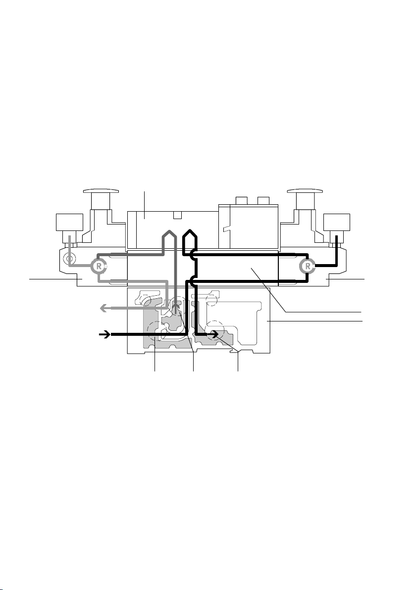
Fig. 1/5 shows the following switching position of the B-pressure regulator:
The working air is passed from duct (1) through the intermediate plate and the valve to the B-pressure regulator, where it
is regulated and then passed to port (2) of the manifold subbase. The exhaust is passed via duct (4) to pressure regulating valve A and then via the valve to duct (5).
2
1
Port (2) (B)
Port (4) (A)
B-pressure regulator
1
2
Valve
3
A-pressure regulator
4
Intermediate plate
Fig. 1/5: AB-pressure regulator
8
67
5
Manifold sub-base
6
Duct (5) (exhaust)
7
Duct (1) (air)
8
Duct (3) (exhaust)
3
4
5
1-24
Festo P.BE-VTSA-44-EN en 1202g
Page 41

1. Overview of components
Reversible AB-pressure regulator (identifier R5-...-6
and R5-...-10)
Pressurizing process With the reversible pressure regulator, the air (duct 1) is
split and routed directly to both pressure regulators. In each
case the regulated air is present in ducts (3) and (5) on the
valve. The valve is thus operated in reversible mode
( Fig. 1/6). This means:
– Duct (3) routes the working pressure to por t (2)
– Duct (5) routes the working pressure to por t (4).
Exhaust process: Venting occurs in the valve from duct (4) or duct (2) to duct
(1) and in the intermediate plate guided to duct (5) or duct
(3) in the manifold sub-base.
Festo P.BE-VTSA-44-EN en 1202g
Advantages compared with the AB-pressure regulator:
– Faster cycle times
– 50 % higher exhaust flow rate, as air is not vented via the
pressure regulator. The load on the pressure regulator is
also reduced.
– No quick exhaust valves are required. The exhaust is duc-
ted completely via the valve terminal.
– Operating pressure is always present at the pressure reg-
ulator, as the pressure is regulated upstream of the valve.
In other words, the regulator can always be adjusted. In
the case of the AB-pressure regulator, the valve must
switch for this.
Disadvantages compared with the AB-pressure regulator:
– No use of 2x2/2-way valves (ident. code: CV, VV) and
2x3/2-way valves (ident. code: K, H, N) is possible
1-25
Page 42

1. Overview of components
in combination with ducted solenoid exhaust (82/84), as
reversible pressure is present at the valve interface.
– No practical combination with an intermediate throttle
plate possible.
Sample applications:
– When, instead of the operating pressure of the valve ter-
minal, two further different pressures are required in
ducts (2) and (4).
– When fast venting is required.
– When the pressure regulator must always be adjustable.
1-26
Festo P.BE-VTSA-44-EN en 1202g
Page 43
1. Overview of components
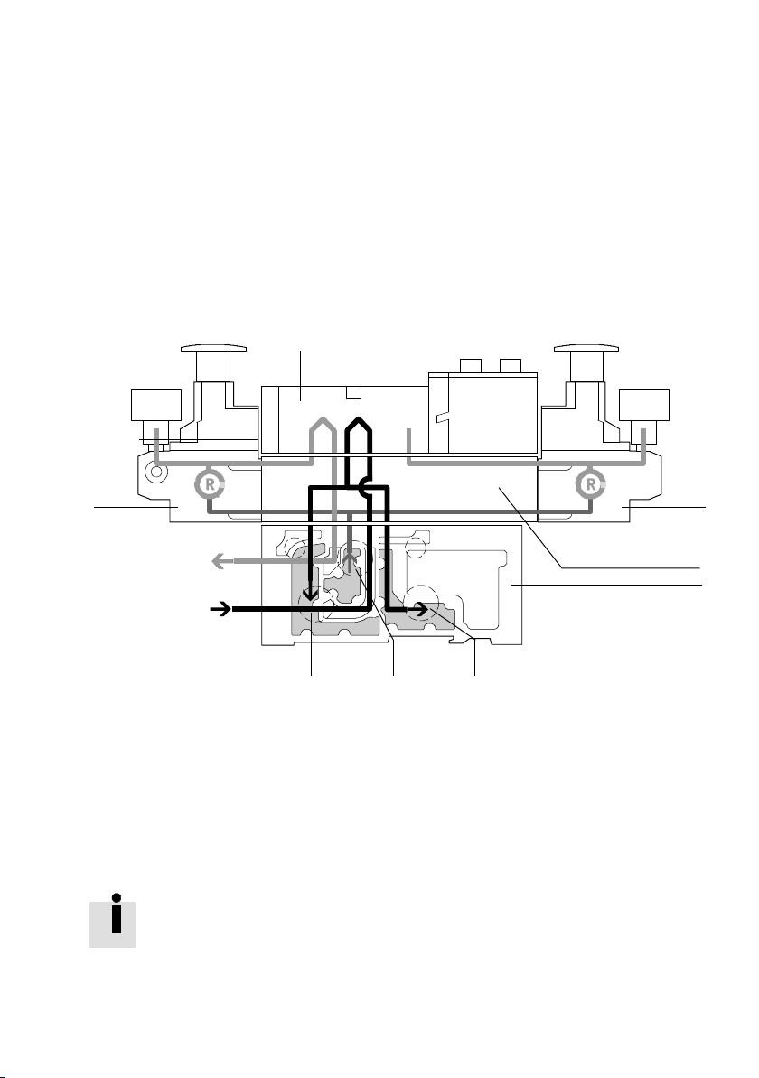
The example below shows the following switching position:
The air in duct (1) is passed in the pressure regulator plate to
pressure regulators A and B, regulated there and then passed
to ports (3) and (5) on the valve. In the valve, the air is routed
to port (2) of the manifold sub-base. The exhaust is conducted via duct (4) in the pressure regulator plate and split there
to ducts (3) and (5) and exhausted.
2
1
Port (2) (B)
Port (4) (A)
8
1
B-pressure regulator
2
Valve
3
A-pressure regulator
4
Intermediate plate
Fig. 1/6: Reversible AB-pressure regulator
For instructions on how to install this pressure regulator
section 3.8.2
67
5
Manifold sub-base
6
Duct (5) (exhaust)
7
Duct (1) (air)
8
Duct (3) (exhaust)
3
4
5
Festo P.BE-VTSA-44-EN en 1202g
1-27
Page 44

1. Overview of components
Flow control plate
This plate is used in vertical stacking for exhaust air flow control in ducts (3) and (5) in order to adjust the speed of the
corresponding actuator.
Vertical pressure shut-off plate
This plate can be used to cut off the corresponding valve in
vertical stacking from the terminal's operating and pilot pressure. Both duct (1) and duct (14) are shut off at the same
time. This means that the valve can be removed without shutting off the pressure.
When operating a valve terminal with a pressure shut-off
plate, pay attention to the instructions in section 3.4.2.
Vertical supply plate
This plate can be used to supply a valve in vertical stacking
with an individual operating pressure independently of the
operating pressure of the terminal.
1.2.8 Components for protective functions
Soft-start valves with piston position sensing
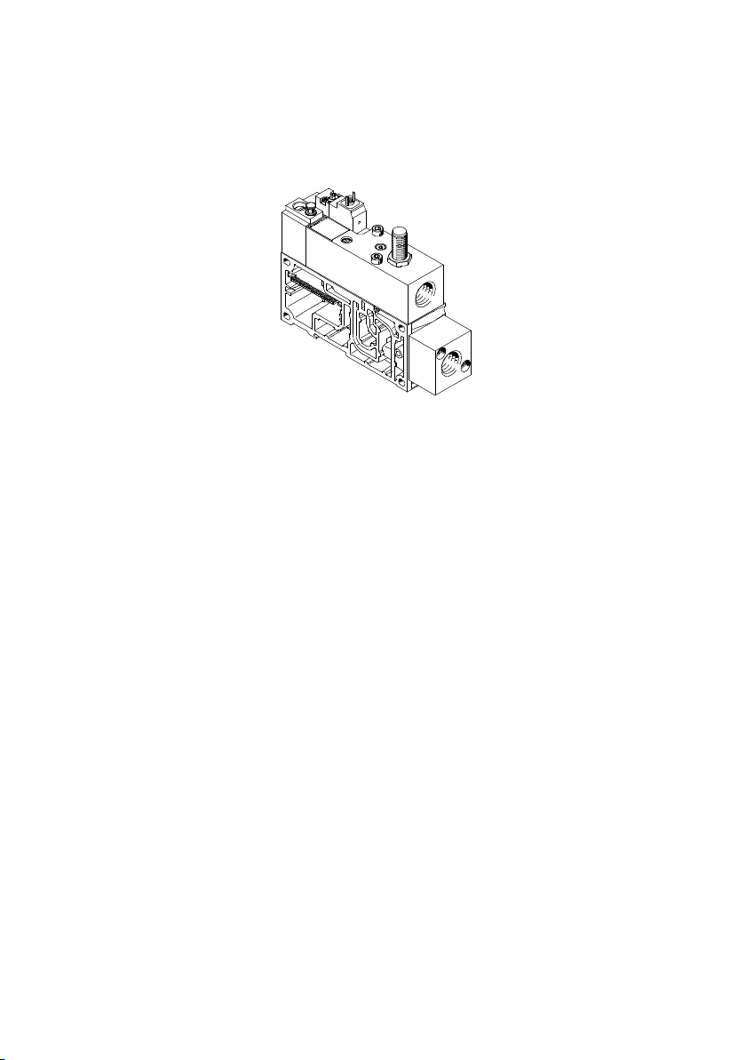
The purpose of the soft-start valve type VABF-S6-1-P5A4-..
(ident. code SR) is to slowly and securely build up the supply
pressure in duct (1) of the valve terminal or to quickly exhaust duct (1) of the valve terminal.
1-28
Festo P.BE-VTSA-44-EN en 1202g
Page 45
1. Overview of components
Fig. 1/7: Soft-start valve
The optimum pressure build-up required by the application
for each pressure zone is configured directly on the valve
terminal by setting the switchover pressure and filling time.
The VTSA/VTSA-F valve terminal can either be operated with
an internal pilot air supply via the soft-start valve or with an
internal or external pilot air supply via the different end
plates. The type of pilot air supply is determined by the seal
of the soft-start valve.
Festo P.BE-VTSA-44-EN en 1202g
The soft-start valve is actuated electrically independently by
the multi-pin/fieldbus connection via a 4-pin plug (in accordance with ISO 15407-1) or separately via an optional M12
adapter.
Switch-on takes place in two stages:
– First the working pressure provided for duct (1) gradually
increases. The speed can be adjusted using a flow control
screw.
– Once the working pressure in duct (1) reaches a previ-
ously set value, the soft-start valve switches the full operating pressure at duct (1) of the valve terminal.
When the valve terminal is supplied with internal pilot air via
the soft-start valve, the full operating pressure is always
present at duct (14). This pressure causes the valves on the
valve terminal to immediately move to the required switching
1-29
Page 46
1. Overview of components
position. When the valve is not switched, duct (1) of the valve
terminal is exhausted via the soft-start valve's exhaust port.
The switching point for full operating pressure is set to 4 bar
at the factory, but can be changed using an adjusting screw.
The piston position of the soft-start valve can optionally be
monitored by an inductive sensor (N/O contact). This sensor
registers whether the valve has switched and therefore
whether the valve terminal is being supplied with air. Due to
the required calibration, the later addition of the sensor by
the customer is not intended. A pressure gauge is optionally
available as a pressure indicator.
Note
– The VTSA valve terminal can be equipped with a maxim-
um of 5 soft-start valves.
– If a soft-start valve is used in the VTSA valve terminal, no
additional pressure-supplying components may be used
inthesamepressurezone.
– Exhaust air cannot be expelled via the soft-start valve. If
a pressure zone is operated with a separate duct (1) and
3/5 duct, an exhaust plate is required in this pressure
zone.
– Instructions for combining the soft-start valve, pneumat-
ic supply plate and the right end plate can be found in
the assembly instructions VABV-S6-1Q-...
1-30
Control block
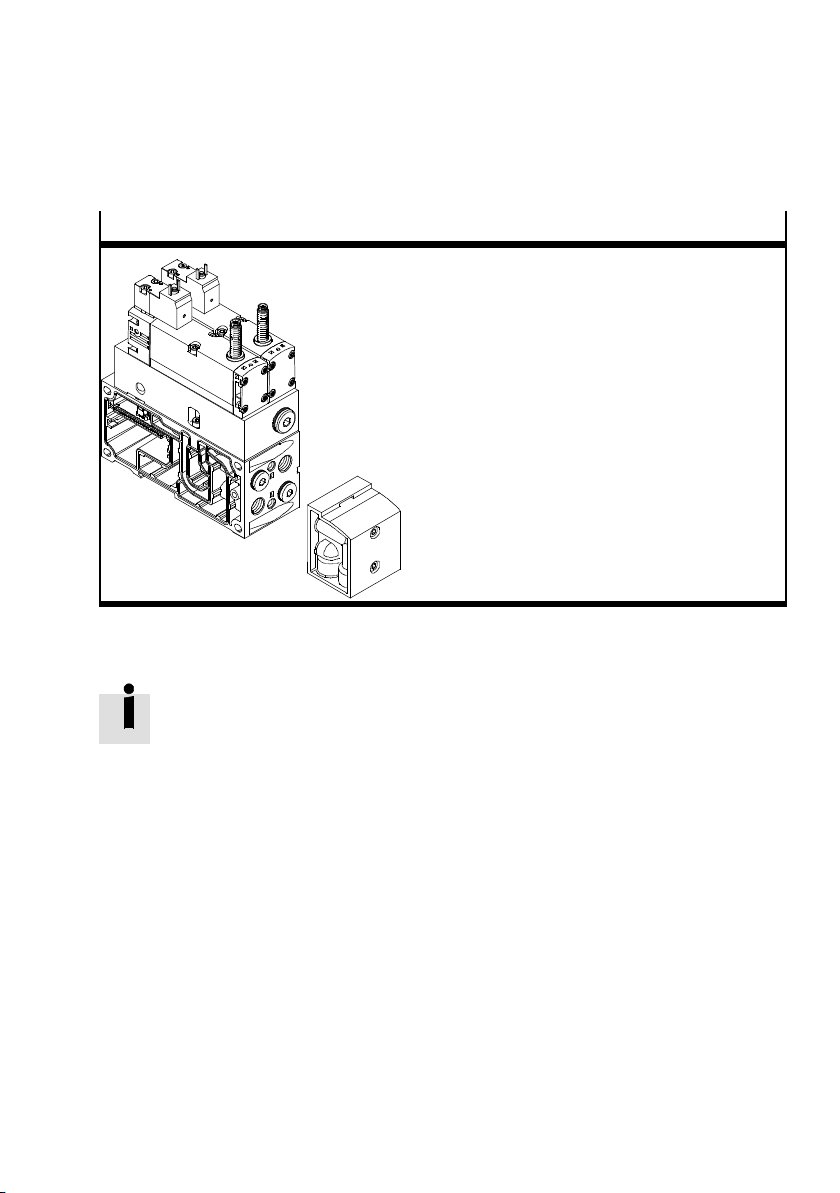
The control block type VOFA-B26-T52-M-... (ident. code SP or
SN) is intended for two-channel control of pneumatic drive
components (e.g. double-acting linear cylinders) and can be
used for implementing the following safety functions:
– Protection against manipulation, prevention of unexpec-
ted start-up (EN 1037)
– Safe reversal of a hazardous movement, provided the
reversing motion itself will not result in further hazards.
Festo P.BE-VTSA-44-EN en 1202g
Page 47
1. Overview of components
Components
Tab. 1/10: Control block
Control block VOFA-B26-T52-M...-1C1...
Optional: 90°-connection plate type
VABF...A1G2... Working connections
(2) and(4) turned 90°
Festo P.BE-VTSA-44-EN en 1202g
The detailed description of the control block can be found in
the operating instructions VOFA-..., which accompany the
product.
1-31
Page 48
1. Overview of components
1.2.9 Manifold sub-base VABF-S4-…-S
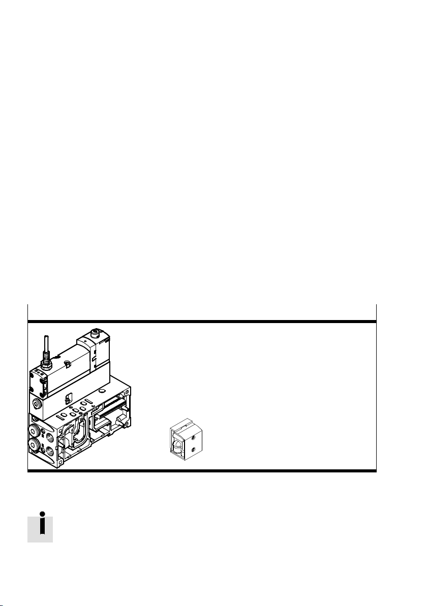
The manifold sub-base type VABF-S4-…-S (ident. code: ZO)
serves to switch the pilot air in combination with a 5/2-way
valve. The pilot air is branched from duct 1 and guided
through the switched 5/2-way valve into duct 14.
Intended combinations:
– Manifold sub-base VABF-S4-…-S in combination with a
5/2-way solenoid valve with piston position sensing type
VSVA-B-M52-MZD-1T1L-A…
– Manifold sub-base VABF-S4-1-S in combination with
“Standard” 5/2-way solenoid valve (without piston position sensing) type VSVA-B-M52-MZD-1T1L and pressure
switch SPBA-B11R-G18-P-M12-0.25X.
Components
Solenoid valve with piston position sensing
type VSVA-B-M52-MZD-1T1L-A...
Manifold sub-base VABF-S4-…-S
optionally with pressure switch type
SPBA-B11R-G18-P-M12--0.25X
Optional: 90°-connection plate type
VABF...A1G2... Working connections
(2) and (4) turned 90°
Tab. 1/11: Components for switching the pilot air supply
Further information appears in the assembly instructions for
the vertical stacking plate.
1-32
Festo P.BE-VTSA-44-EN en 1202g
Page 49
1. Overview of components
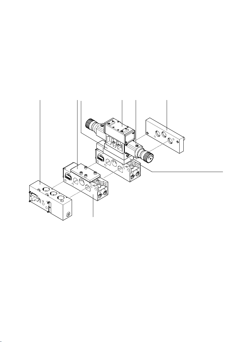
1.3 Pneumatic components, width 65 mm
The VTSA... valve terminal with adaptation of type 04-B pneumatics in width 65 mm (ISO 3) consists of the following pneumatic components:
12345
6
8
1
Adapter plate
2
Blanking plate
3
Flow control plate
4
Valve
5
Pressure regulator plate
6
right end plate
7
Intermediate solenoid plate MUH
8
Manifold sub-base
7
Fig. 1/8: Pneumatic components of the VTSA... valve terminal, width 65 mm
Festo P.BE-VTSA-44-EN en 1202g
1-33
Page 50
1. Overview of components
1.3.1 Valves
ThefollowingvalvefunctionsareavailablefortheVTSA...
valve terminal in width 65 mm:
– 5/2-way valves, (monostable or bistable)
– 5/3-way mid-position valves
Valves of width 65 mm (ISO 3) can be operated on the the
VTSA-…valveterminalasfollows:
– Standard operation
– Reversible operation
– Low pressure
– Vacuum
Identifying the valves Valves of width 65 mm are identified by type code. The type
code is printed on the rear of the valve. An identifier within
thetypecodeindicatesthefunctionofthevalve.Forexample, identifier 5/2-...-FR inthetypecode
MUH-5/2-D-3-FR-C-VI means that the valve is a monostable
5/2-way valve with mechanical spring. You can identify the
valve function with the aid of the following table. In the sales
documentation and in the Festo Configurator the valves are
marked with an Ident. code.
1-34
Festo P.BE-VTSA-44-EN en 1202g
Page 51
1. Overview of components
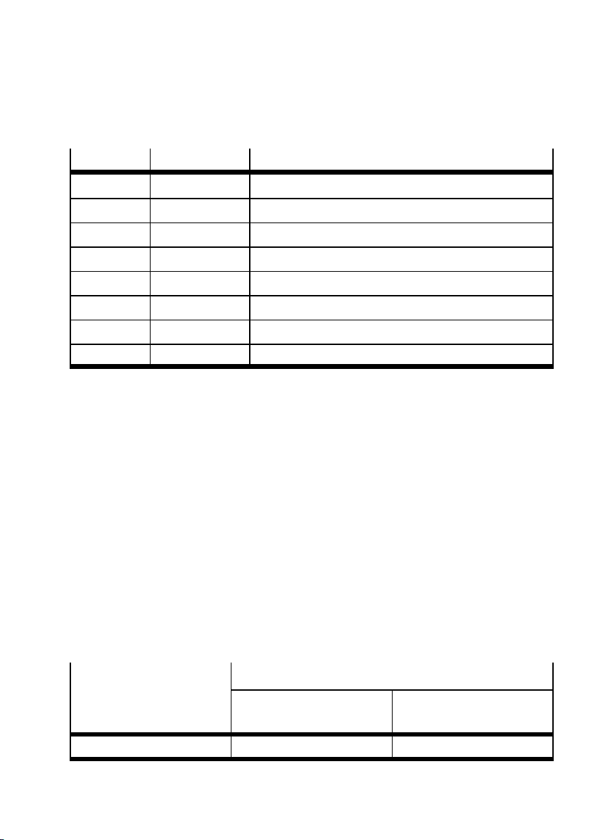
Ident. code Indicator in type Pneumatic components
B ...5/3B-... 5/3-way valve, mid-position pressurised
D JDMUH-5/2-... 5/2-way impulse valve, dominating signal
E ...5/3E-... 5/3-way valve, mid-position exhausted
G ...5/3G-... 5/3-way valve, mid-position closed
J JMUH-5/2-... 5/2-way impulse valve
L IAP-04-D-3 Cover plate for non-assigned valve location
M ...5/2-...-L... 5/2-way valve, monostable, pneumatic spring return
O ...5/2-...-FR... 5/2-way valve, monostable, spring return
Tab. 1/12: Valve identification (width 65 mm)
1.3.2 Manifold sub-bases
The number of electrically controllable valve positions depends on the manifold sub-bases and the electrical connection used ( Tab. 1/2).
If only manifold sub-bases that support the control of two
solenoid coils per valve position are used, any type of valve
can be placed in any valve position.
If, on the other hand, only manifold sub-bases that control
only one solenoid coil per valve position are used, the valve
terminal can only be equipped with monostable 5/2-way
valves (ident. code M or O) or cover plates.
Identification features
Type code VIGM-04-D-3 VIGI-04-D-3
Manifold sub-bases, width 65 mm
for actuating one solenoid
coil per valve position
for actuating two solenoid
coils per valve position
Tab. 1/13: Identification of the manifold sub-bases, width 65 mm
Festo P.BE-VTSA-44-EN en 1202g
1-35
Page 52

1. Overview of components
1.3.3 Pilot control
1.3.4 Vertical stacking
The VTSA valve terminal of width 65 mm can be operated with
a maximum of two pressure zones. These pressure zones are
formed by isolating discs. These are inserted between the
manifold blocks in the supply duct (1) and, for special cases,
in the air exhaust ducts (3 or 5) as well. The first pressure
zone is supplied with compressed air via the adapter plate,
while the second pressure zone is supplied via the right end
plate.
You can mount further pneumatic components in each location between the manifold sub-base and the valve. These
vertical stackings enable you to implement certain additional
functions as desired. The following diagram shows the available components:
1-36
Tab. 1/14 shows the basic design and possible components
of vertical stacking.
Festo P.BE-VTSA-44-EN en 1202g
Page 53
1. Overview of components
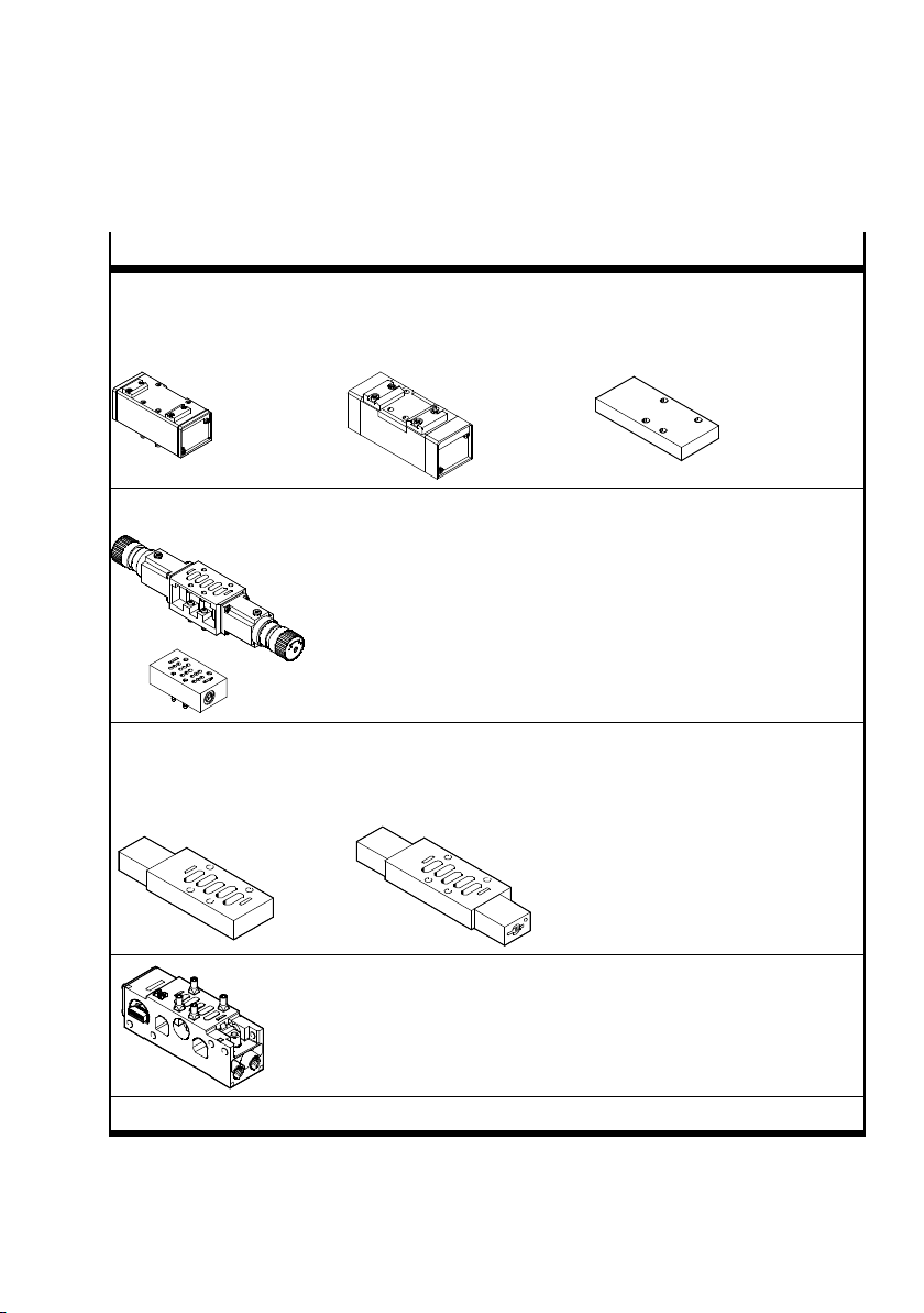
y
1
)
Components (width 65)
monostable 5/2-wa
valves type
MUH-5/2-D-.3...-VI
Alternatively:
5/2-way valve, bistable type:
JMUH-5/2-D-...-C-VI or 5/3-way
valve MUH-5/3..-D-3...-VI
Vertical stacking, optional components:
Pressure regulator plate type: LR-ZP-...-D-3 (with or without
pressure gauge)
Flow control plate type: G RO-ZP-3
Intermediate solenoid plate
with one solenoid coil,
pilot valve and non-detenting
manual override
Intermediate solenoid plate with 2 solenoid coils,
pilot valve and non-detenting manual override
type: MUH-5/3...-D-3-..., JMUH-...-D-3...-VI
or JDMUH-...-D-3...-VI
type: MUH-5/2-D-3...-VI
Alternatively:
Cover plate, for sealing an unused
valve position
type: IAP-04-D-...
1)
1)
Manifold sub-base type VIGM-04-D-3 which supports the actuation of one solenoid coil or
Manifold sub-base type VIGI-04-D-3 which supports the actuation of two solenoid coils
1) Instructions on installing the vertical stacking componentschapter 3
Tab. 1/14: Components of the pneumatic module of the VTSA... valve terminal Width
65 mm
Festo P.BE-VTSA-44-EN en 1202g
1-37
Page 54
1. Overview of components
The vertical stacking components of width 65 mm are designated by a type code on the valve terminal. The code is printed on the side of the component. Identification within the
type code indicates the function of the components, e.g. type
code LR-ZP-A-D-3 indicates that this component is an A-pressure regulator. Y o u can identify the vertical stacking components with the aid of the following table. In the sales documentation and in the Festo Configurator, the components are
marked with an ID code.
Label in the
type code
...-P-... ZA Pressure regulator intermediate plate, port 1
...-A/B-... ZD Pressure regulator intermediate plate, ports 2 and 4
...-A-... ZB Pressure regulator intermediate plate, port 4
...-B-... ZC Pressure regulator intermediate plate, port 2
GRO-ZP-3-ISO-B X Throttle plate with 2 one-way flow control valves for restricting the
Ident.code
Pneumatic components
exhaust
Tab. 1/15: Ident. code of the vertical stacking components
Flow control plate
This flow control plate is used in vertical stacking for exhaust
air flow control in ducts (3) and (5) in order to adjust the
speed of the corresponding actuator.
1.4 Connection and control elements of the pneu. components, width 18 ... 52 mm
The description of the connection, display and control elements for the control block can be found in the corresponding
operating instructions accompanying the product.
1-38
Festo P.BE-VTSA-44-EN en 1202g
Page 55
1. Overview of components
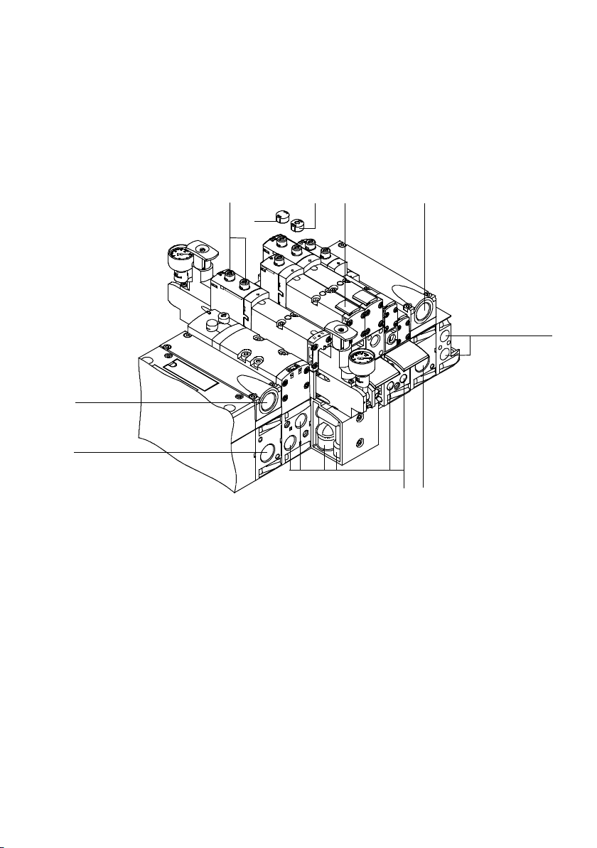
You will find the following pneumatic connection and control
elements on the VTSA... valve terminal:
12 34
5
7
1
Manual override (per pilot solenoid,
non-detenting or turning with detent)
2
Optional manual override cover cap
(manual override without function)
3
Optional manual override cover cap,
for non-detenting function of manual
override
5
8 7
5
Exhaust ports “Valves” (3/5)
6
Pilot connections (12) and (14) for
supplying the external pilot air
7
Supply port (1) “Operating pressure”
8
Working lines (2) and (4), per valve
position
6
4
Inscription areas
Fig. 1/9: Pneumatic Connection, display and operating elements of the basic compon-
ents, width 18 ... 52 mm
Festo P.BE-VTSA-44-EN en 1202g
1-39
Page 56
1. Overview of components
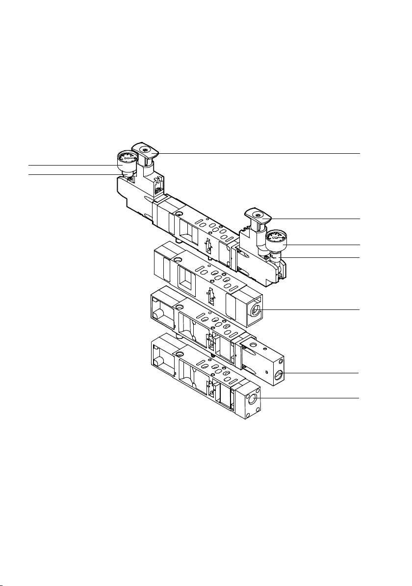
2
1
Pressure regulator plate
Flow control plate
You will find the following connection and contr ol elements on
the vertical stacking components:
3
3
2
1
Vertical pressure shut-off
plate
Vertical supply plate
1
Connection for manometer (can be
turned 90°)
2
Pressure gauge (optional)
3
Adjusting knob with grid locking (with
widths 18 mm and 26 mm, with freewheel unit)
Fig. 1/10: Connection and control elements of the vertical stacking components, width
18 ... 52 mm
1-40
4
Adjusting screw for throttle flow (for
widths 42 mm and 52 mm only on the
right-hand side)
5
Operating pressure plug screw for one
valve position
6
Port (1) (individual operating pressure
for one valve position)
Festo P.BE-VTSA-44-EN en 1202g
4
5
6
Page 57
1. Overview of components
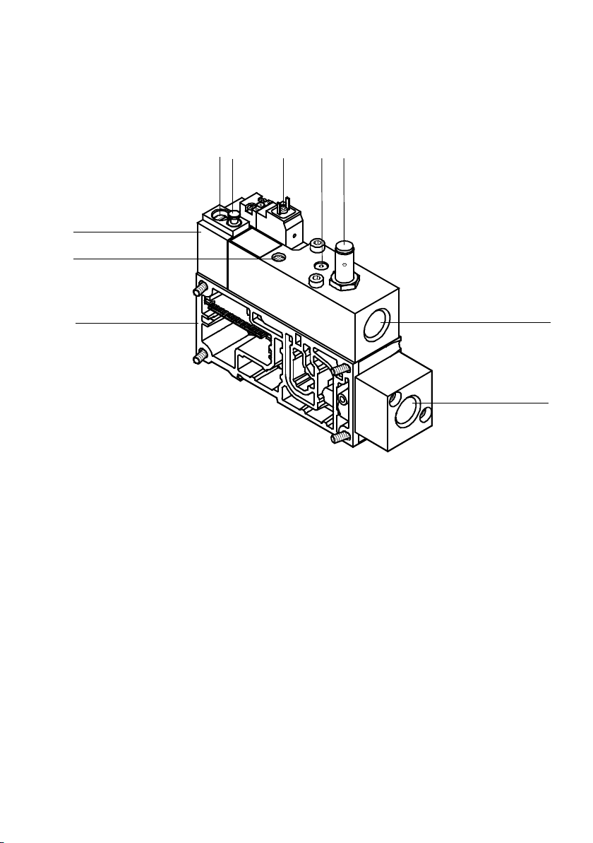
123 4
aJ
9
8
“Switchover pressure” adjusting
1
screw
2
Self-resetting manual override
(non-detenting)
3
Electrical terminal for solenoid coil
5
6
exhaust connection (3/5)
7
Supply port (1)
8
Manifold sub-base
9
“Air supply time” flow control screw
6
7
aJ
4
Port for optional pressure gauge
5
Sensor for sensing the piston position
Fig. 1/11: Connecting and operating elements of the soft-start valve
Festo P.BE-VTSA-44-EN en 1202g
Soft-start valve
1-41
Page 58
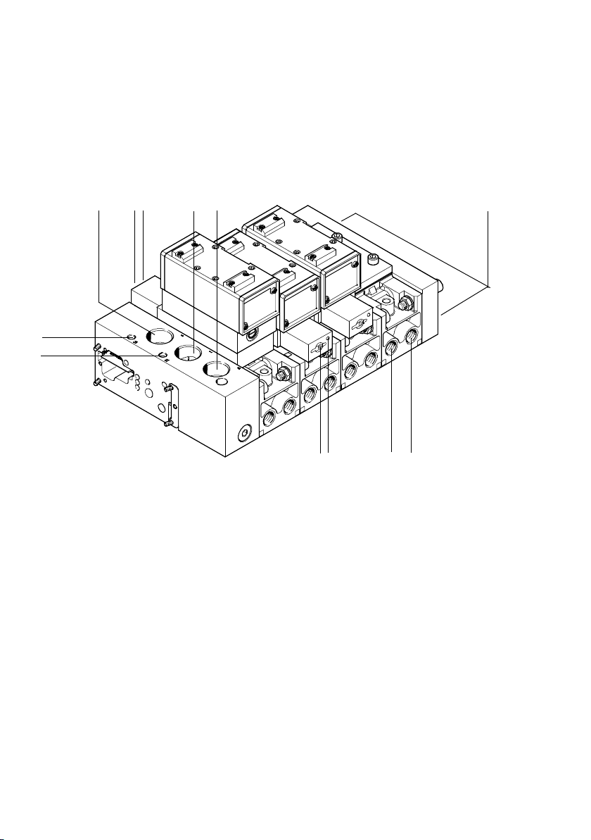
1. Overview of components
1.5 Connection, display and operating elements of the pneu. Components, width 65 mm
1 234 5 6
aB
aA
789aJ
Exhaust port (5) “Valves”
1
2
Yellow LED (for each solenoid coil 14)
3
Manual override (MO)
(for each solenoid coil 14,
non-detenting)
4
Supply port (1)
“Operating pressure”
5
Exhaust port (3) “Valves”
6
Portsintherightendplate:
– supply ports (5), (1) and (3).
– ports (14) and (12) for pilot control of
thevalvesofwidth65mm
Fig. 1/12: Pneumatic Connection, display and control elements of the basic components,
width 65 mm
1-42
7
Yellow LED (for each solenoid coil 12)
8
MO (for each solenoid coil 12,
non-detenting)
9
Working port (2) in the manifold
sub-base, front and optionally
underneath (for each valve)
aJ
Working port (4) in the manifold
sub-base, front and optionally
underneath (for each valve)
aA
Pilot port (12) for supplying the valves
of width 18 … 52 mm
aB
Pilot port (14) for supplying the valves
of width 18 … 52 mm
Festo P.BE-VTSA-44-EN en 1202g
Page 59
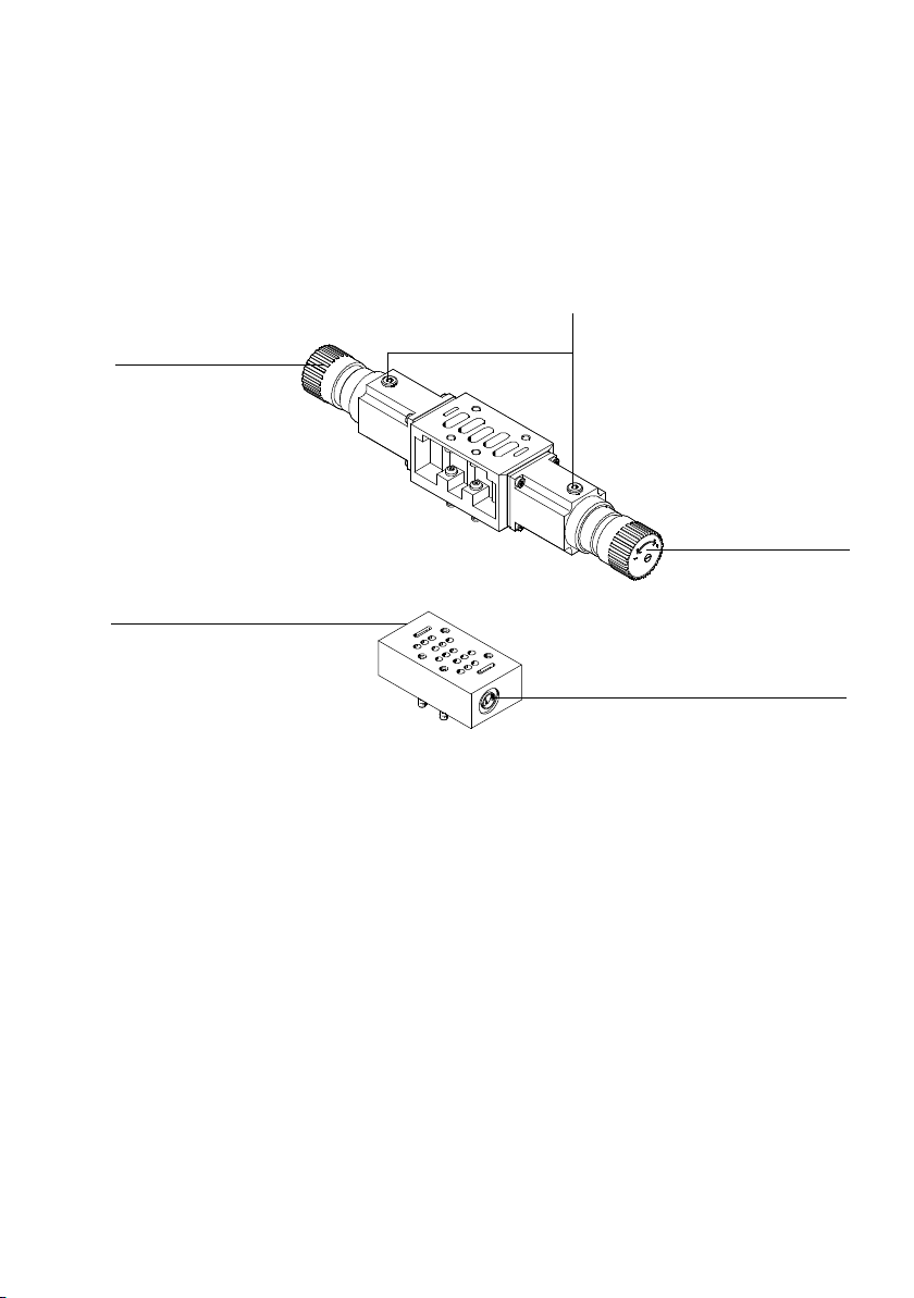
1. Overview of components
You will find the following connection and contr ol elements on
the vertical stacking components:
Intermediate
pressure regulator plate:
2
1
Flow c ontrol
plate:
4
1
Rotary knob with snap-in lock (for
adjustment: pull knob out of locking
position and turn)
2
Connection for manometer
Fig. 1/13: Connection and control elements of the vertical stacking components, width
65 mm
3
Adjusting screw for throttle flow (3)
4
Adjusting screw for throttle flow (5)
1
3
Festo P.BE-VTSA-44-EN en 1202g
1-43
Page 60
1. Overview of components
1.6 Electrical components
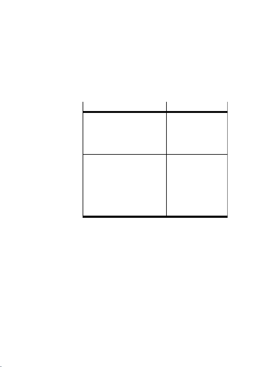
The VTSA... valve terminal is available with the following electrical connection variants:
Valve terminals VTSA
fieldbus variants:
– with CPX terminal
(
Fig. 1/14)
– withtype03electronics
(
Fig. 1/16)
– AS-interface (see Fig. 1/17)
Multi-pin alternative connections:
– Sub-D connection
(
Fig. 1/18)
–Cageclamp
(
Fig. 1/19)
– Multi-pin node, M23 round plug
(
Fig. 1/20)
– Multi-pin node IC
(
Fig. 1/21)
1.6.1 VTSA... valve terminal with fieldbus
The electrical connection of the solenoid coils to the CPX terminal or the bus node FB21 (type 03) takes place centrally via
the pneumatic interface ( following images). Per valve position, one or two solenoid coils (dependent on the manifold
sub-base) and within the valve terminal, a maximum of 26 or
32 solenoid coils are controlled via the CPX terminal
( Tab. 1/2).
Valve pilot via
– CPX-fieldbus.
– Fieldbus FB 21 type 03
–AS-interface
– 37-pin sub-D multi-pin
plug socket
– Central over the terminal
strip
– Central over the 18-pin
M23 round plug
– Take places individually
over6or10ICconnections
1-44
Festo P.BE-VTSA-44-EN en 1202g
Page 61
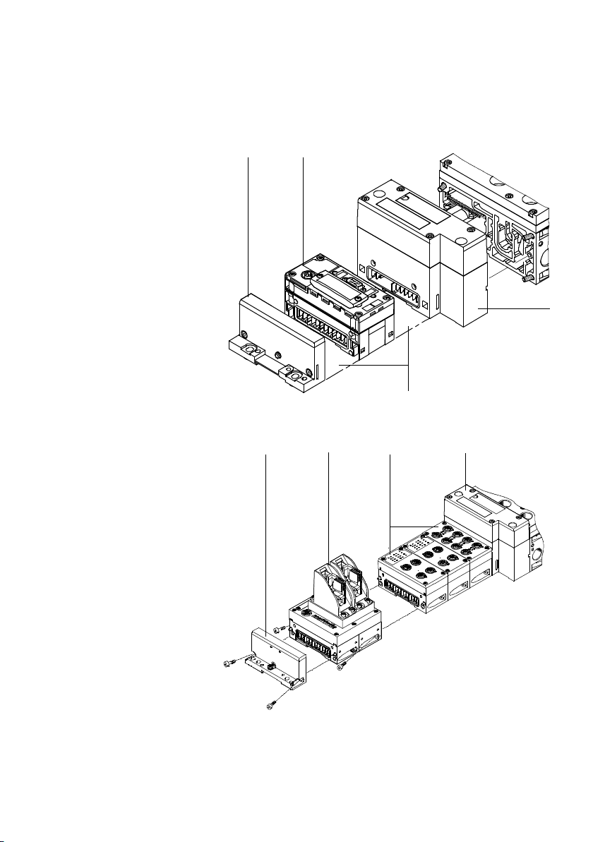
1. Overview of components
1
Left end plate
(CPX)
2
CPX bus node
3
Pneumatic
interface
4
Further optional
CPX modules
1
2
4
Fig. 1/14: Electric components of the VTSA... valve terminal with CPX terminal
3
1
Left end plate
(type 03):
2
FB 20 or FB 21
3
Further optional
CPX modules
4
Pneumatic
interface
Fig. 1/15: Electric components of the VTSA... valve terminal with CPX-M-FB20 or FB21
Festo P.BE-VTSA-44-EN en 1202g
1
23
4
1-45
Page 62
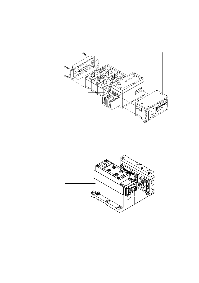
1. Overview of components
1
Left end plate
(type 03):
2
FB 21
3
Pneumatic
interface
4
Further optional
type 03 modules
1
23
4
Fig. 1/16: Electric components of the VTSA... valve terminal with FB 21, type 03
1
AS-interface
2
Multi-pin node
1
2
Fig. 1/17: Electric components of the VTSA... valve terminal with AS-interface
1.6.2 VTSA... valve terminal with multi-pin
The electrical connection of the solenoid coils is made centrally via a multi-pin plug connection that is available in different variants at the VTSA valve terminal ( following images).
Dependent on the manifold sub-bases, one or two solenoid
1-46
Festo P.BE-VTSA-44-EN en 1202g
Page 63
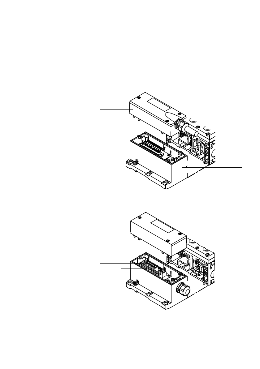
1. Overview of components
1
Multi-pin plug
cover with cable
2
Multi-pin node
3
Sub-D connection
coils can be controlled per valve position ( Tab. 1/3). Each
solenoid coil occupies a pin/terminal of the multi-pin plug
connection.
1
3
2
Fig. 1/18: Electric components of the VTSA... valve terminal with multi-pin node sub-D
1
Cover
2
Protective
conduit with
strain relief
3
Multi-pin node
4
Cage clamp
1
4
3
Fig. 1/19: Electric components of the VTSA... valve terminal with multi-pin node cage
clamp
Festo P.BE-VTSA-44-EN en 1202g
2
1-47
Page 64
1. Overview of components
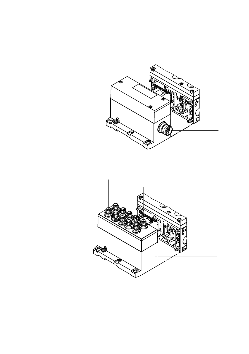
1
Multi-pin node
2
M23 round plug
1
Fig. 1/20: Electric components of the VTSA... valve terminal with multi-pin node M23
round plug
1
IC connections
2
Multi-pin node
1
2
Fig. 1/21: Electric components of the VTSA... valve terminal with multi-pin node IC
1-48
Festo P.BE-VTSA-44-EN en 1202g
2
Page 65
1. Overview of components
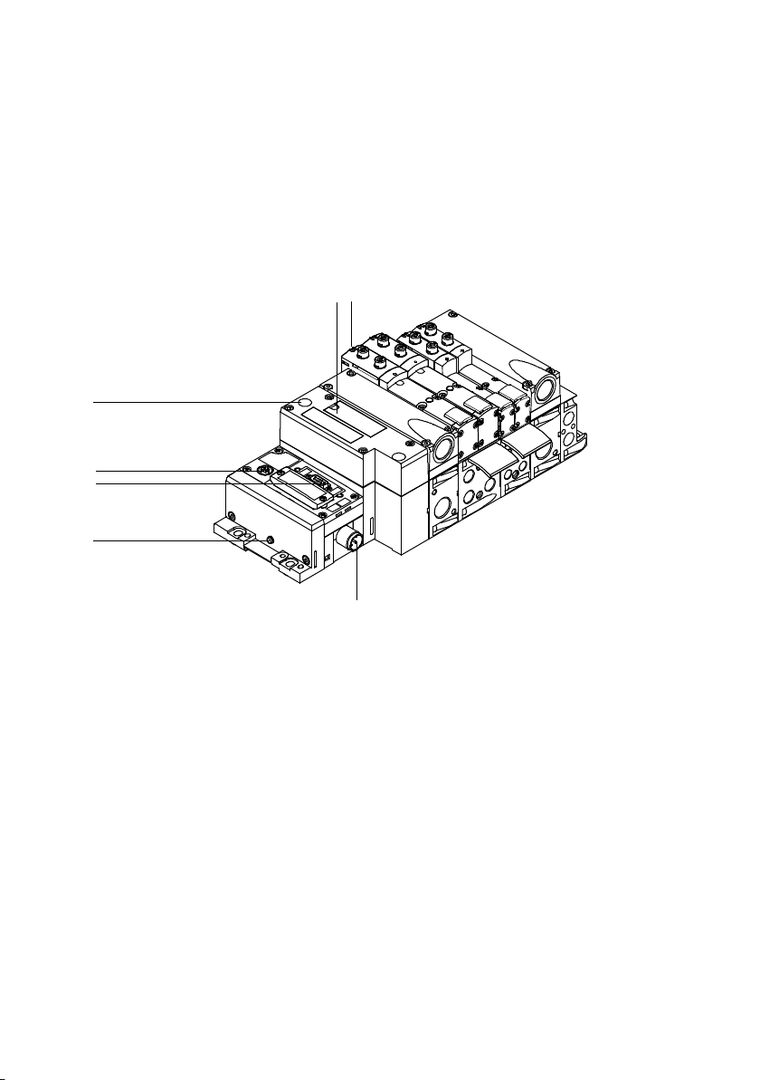
1.7 Connection and display components of the electrical components
You will find the following electrical connection and display
components on the VTSA... valve terminal with CPX terminal:
1
2
7
6
5
4
3
1
Inscription field and cover for H-rail
mounting screw
2
yellow LEDs: signal status display of
the pilot solenoid coils
3
Power supply connection
4
Earth terminal
Fig. 1/22: Electrical connecting, display and operating elements of the VTSA... valve ter-
minal with CPX terminal
Festo P.BE-VTSA-44-EN en 1202g
5
Fieldbus connection
(fieldbus-specific)
6
Service interface for handheld, etc.
7
red LED: common error display of the
valves
1-49
Page 66
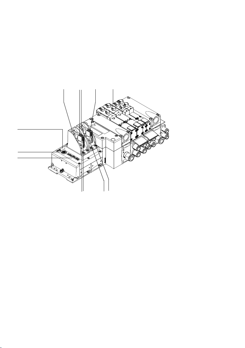
1. Overview of components
2
1
aB
aA
aJ
You will find the following electrical connection and display
components on the VTSA... valve terminal with CPX-M-FB 20
or FB 21:
4 5
3
9
1
vertical INTERBUS fibre optic cable
interface (incoming)
2
vertical input of the power supply
connection (incoming)
3
vertical INTERBUS fibre optic cable
interface (continuing)
4
vertical output of the power supply
connection (continuing)
5
yellow LEDs: signal status display of
the pilot solenoid coils
6
horizontal output of the power supply
connection (continuing)
Fig. 1/23: Electrical connection, display and control elements of the VTSA... valve terminal
with CPX-M-FB20 or FB21
1-50
678
7
horizontal INTERBUS fibre optic cable
interface (continuing)
8
horizontal output of the power supply
connection (incoming)
9
horizontal INTERBUS fibre optic cable
interface (incoming)
aJ
LEDs electronics description CPXM-20/21 INTERBUS fibre optic cable
remote bus “Rugged Line”
aA
Service interface for handheld, etc.
aB
DILswitch(underthecover)
Festo P.BE-VTSA-44-EN en 1202g
Page 67
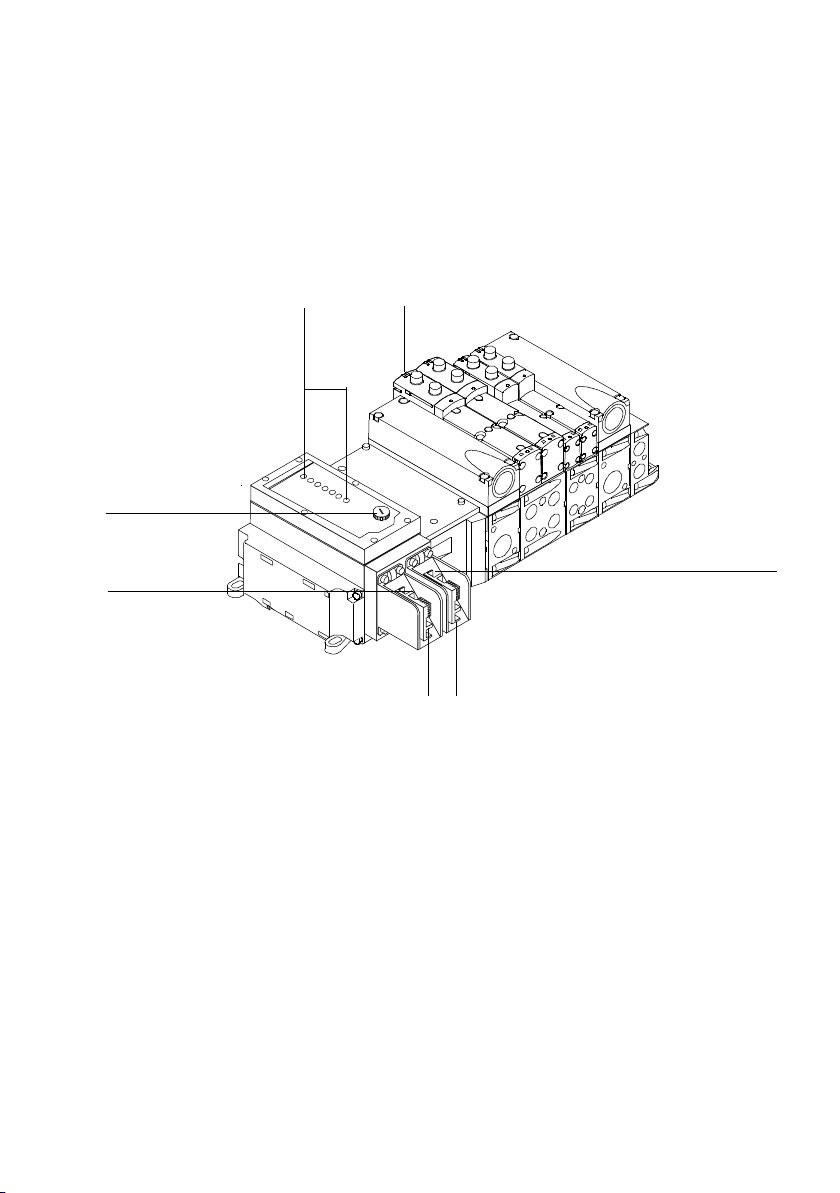
1. Overview of components
7
You will find the following electrical connection and display
components on the VTSA... valve terminal with FB 21,
type 03:
12
6
5
1
LEDs description of type 03 electronics INTERBUS fibre optic cable remote bus “Rugged Line”
2
yellow LEDs: signal status display of
the pilot solenoid coils
3
INTERBUS fibre optic cable interface
(continuing)
4
Output of the power supply connection (continuing)
Fig. 1/24: Electrical connecting, display and operating elements of the VTSA... valve ter-
minal with FB 21, type 03
Festo P.BE-VTSA-44-EN en 1202g
4
5
Input of the power supply connection
(incoming)
6
INTERBUS fibre optic cable interface
(incoming)
7
Fuse for operating voltage of inputs
1-51
3
Page 68
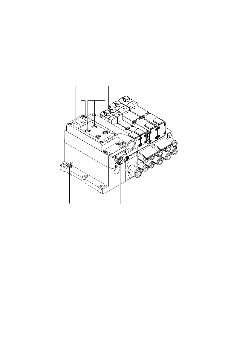
1. Overview of components
You will find the following electrical connection and display
components on the VTSA... valve terminal with AS-interface:
123
8
1
Status LEDs for inputs
2
Status LED AS-interface
(Fault, AUX/PWR)
3
Inputs
4
yellow LEDs: signal status display of
the pilot solenoid coils
4
67
5
5
M12 socket for AS-interface bus and
additional supply (AS-i Out)
6
M12 plug for AS-interface bus and additional power supply (AS-i In)
7
External earth connection
8
Inscription field
Fig. 1/25: Electrical connection and display components of the VTSA... valve terminal with
AS-interface
1-52
Festo P.BE-VTSA-44-EN en 1202g
Page 69
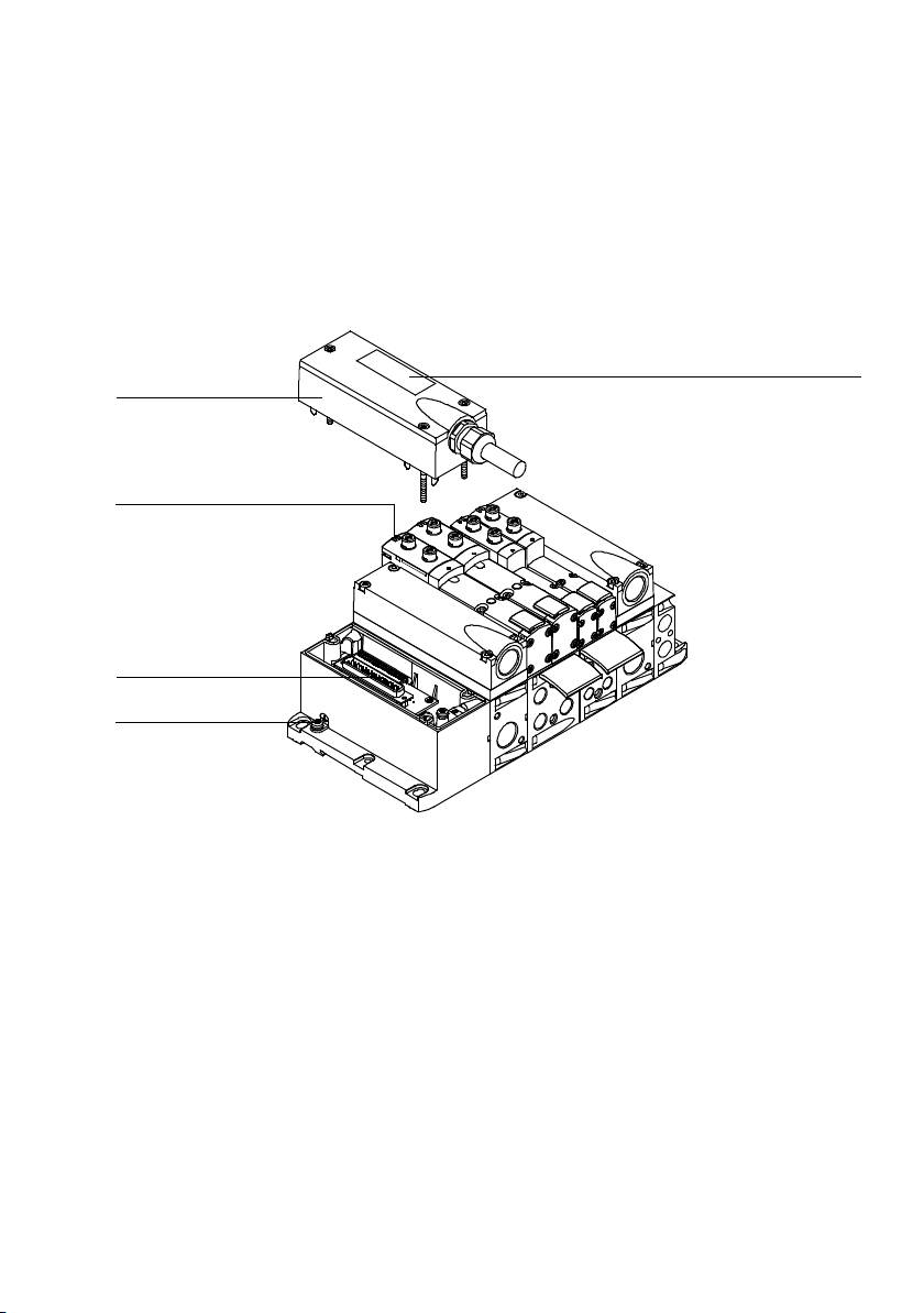
1. Overview of components
1
5
4
You will find the following electrical connection and display
components on the VTSA... valve terminal with multi-pin node
Sub-D:
2
3
Sub-D multi-pin socket with cable
1
2
Inscription field
3
Earth terminal
Fig. 1/26: Electrical connection and display components of the VTSA... valve terminal with
multi-pin node Sub-D
Festo P.BE-VTSA-44-EN en 1202g
4
Sub-D connection
5
yellow LEDs: signal status display of the
pilot solenoid coils
1-53
Page 70
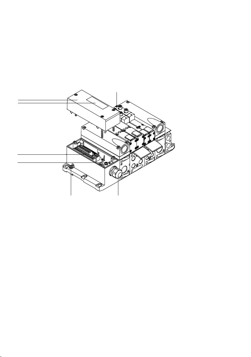
1. Overview of components
You will find the following electrical connection and display
components on the VTSA... valve terminal with multi-pin node
cage clamp:
1
2
7
6
5
4
1
Cover
2
yellow LEDs: signal status display of the
pilot solenoid coils
3
Cable routing
Fig. 1/27: Electrical connection and display components of the VTSA... valve terminal with
cage clamp multi-pin node
3
4
External earth connection
5
Internal earth terminal for the connecting cable
6
Terminal strip
7
Inscription field
1-54
Festo P.BE-VTSA-44-EN en 1202g
Page 71
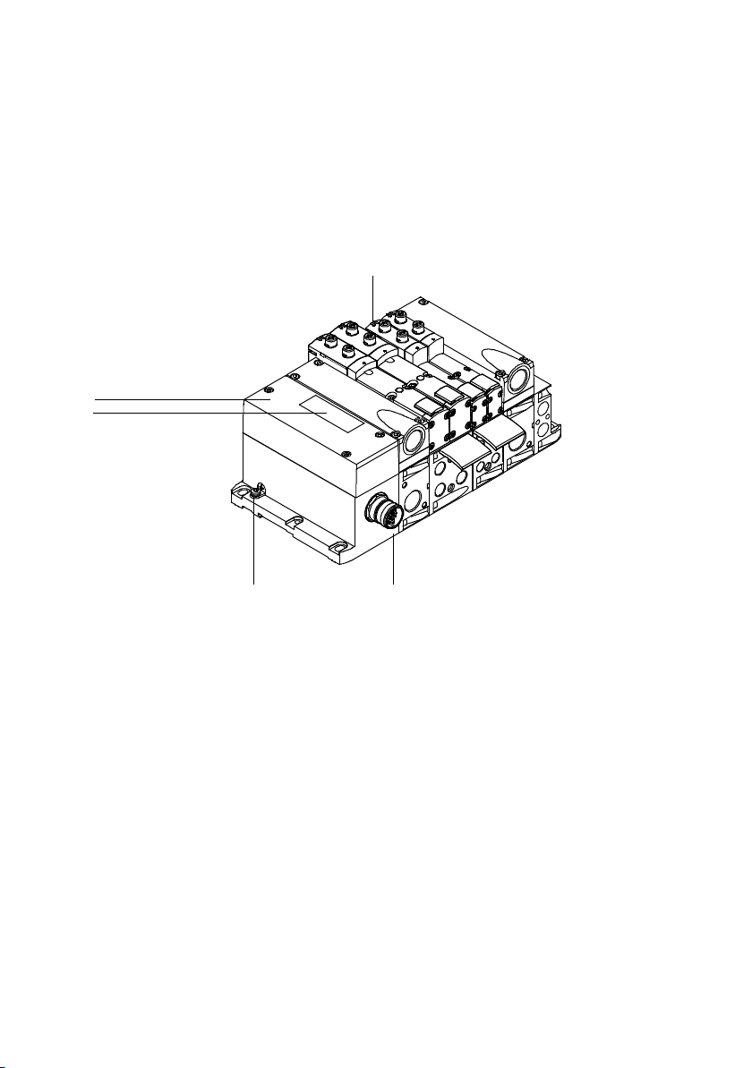
1. Overview of components
1
5
You will find the following electrical connection and display
components on the VTSA... valve terminal with multi-pin node
M23 round plug:
2
4
1
Cover
2
yellow LEDs: signal status display of the
pilot solenoid coils
3
M23 round plug as per CNOMO
E03.62.530.N
Fig. 1/28: Electrical connection and display components of the VTSA... valve terminal with
multi-pin node M23 round plug
Festo P.BE-VTSA-44-EN en 1202g
3
4
External earth connection
5
Inscription field
1-55
Page 72
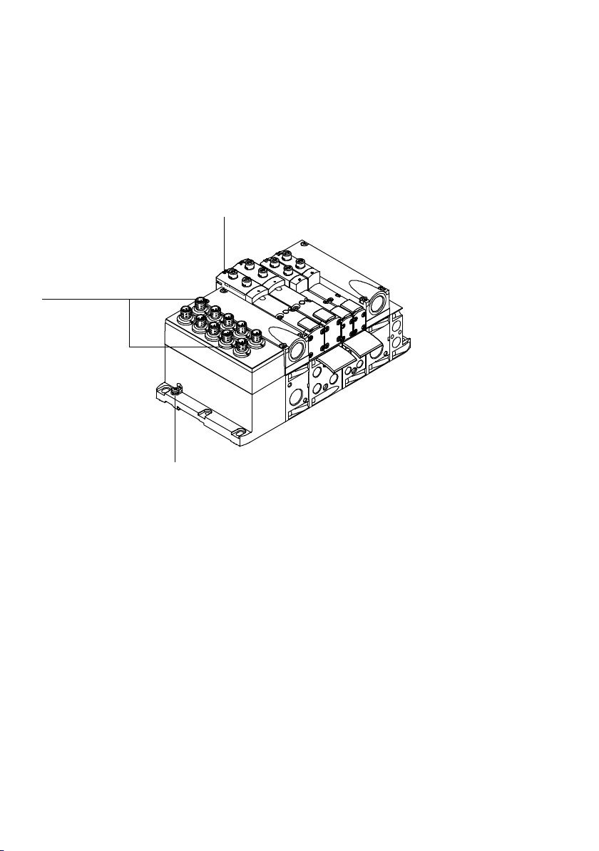
1. Overview of components
1
You will find the following electrical connection and display
components on the VTSA... valve terminal with multi-pin
node IC:
2
3
1
M12 individual connections (IC)
2
yellow LEDs: signal status display of the
pilot solenoid coils
Fig. 1/29: Electrical connection and display components of the VTSA... valve terminal with
multi-pin node IC
1-56
3
External earth connection
Festo P.BE-VTSA-44-EN en 1202g
Page 73

Mounting
Chapter 2
Mounting
Festo P.BE-VTSA-44-EN en 1202g
2-1
Page 74

2. Mounting
Contents
2. Mounting 2-1.....................................................
2.1 General instructions on assembly and dismantling 2-4....................
2.2 Mounting variants 2-5..............................................
2.2.1 Mounting/dismounting on H-rails 2-6..........................
2.2.2 Mounting/dismounting on walls 2-10...........................
2.3 Mounting/dismounting the optional inscription label holder,
width 18 ... 52 mm 2-16..............................................
2.4 Mounting/dismounting the optional manual override cover caps,
width 18 ... 52 mm 2-17..............................................
2-2
Festo P.BE-VTSA-44-EN en 1202g
Page 75

2. Mounting
Contents of this chapter The VTSA... valve terminal is factory pre-assembled.
This chapter describes how to mount and dismount:
– the entire valve terminal (H-rail and/or wall mounting)
– The mounting bracket for wall mounting
– The inscription label holders
– The manual override caps
Additional information Specific information about replacing or adding pneumatic
components can be found in chapter 5.
VTSA... valve terminal with CPX terminal or FB21 (type 03):
– Information for mounting the valve terminal with CPX ter-
minal can be found in the CPX system description.
– Information on connecting and dismantling the I/O mod-
ules can be found in the manual for the CPX I/O modules
or in the additional description of type 03 I/O modules.
Festo P.BE-VTSA-44-EN en 1202g
– Information on mounting modules and components
ordered at a later stage can be found in the package
insert.
2-3
Page 76
2. Mounting
2.1 General instructions on assembly and dismantling
Warning
Sudden unexpected movements of the connected actuators and uncontrolled movements of loose tubing can cause
injury to human beings or damage to property.
Before carrying out mounting, installation and maintenance work, switch off the following:
– Compressed air supply
– Operating and load voltage supplies.
Note
Handle all modules and components of the valve terminal
with great care. Pay particular attention to the following:
– The specified torques must be complied with.
– Screw connections must be fitted without distortion and
mechanical tension. Position screws exactly before tight-
ening (otherwise their threads will be damaged).
– The modules must not be offset (IP 65).
– Contact surfaces must be clean (avoid leakage and con-
tact faults).
– Seal unused valve locations with the appropriate cover
plate (must be ordered separately).
– Electrostatically sensitive devices.
Therefore do not touch any contact areas.
– Valve terminals with Sub-D multi-pin node:
Protect the multi-pin node from moisture, dirt, dust, etc.
until the multi-pin plug socket is fitted with a cable.
2-4
Festo P.BE-VTSA-44-EN en 1202g
Page 77
2. Mounting
2.2 Mounting variants
You can mount the VTSA... valve terminal in one of two ways:
Mounting
Description
method
Hat rails Apart from the VTSA valve terminal with FB 21 (type 03) and the valve terminalwith
Wall Width18...52mm:
pneumatics in a width of 65 mm, all of the other valve terminal variants are suitable
for mounting on an H-rail (mounting rail according to EN 60715).
Please observe the safety instructions in the following section for further information.
A guide groove is located at the rear of the valve terminalfor connecting it to the
H-rail.
The multi-pin node, the pneumatic interface and the end plates contain holes for
mounting the terminal onto a wall.
Additional mounting brackets on the pneumatic supply plates may be required for
valve terminals with more than 5 manifold sub-bases (
and specifications regarding vibration and shock can be found in Appendix A,
Tab. A/5.
Width65mm
The adapter, the manifold sub-bases and the pneumatic interface include holes for
wall mounting.
When mounting on machines or metal frames also use the blind holes on the rear of
the manifold sub-bases (rear mounting).
subsequent information
Fig. 2/1: Methods of mounting the VTSA... valve terminal
Note
Mount the VTSA... valve terminal in such a way that ensures sufficient space for heat dissipation and compliance
with the temperature limit values ( Appendix A, Technical data).
Festo P.BE-VTSA-44-EN en 1202g
2-5
Page 78

2. Mounting
2.2.1 Mounting/dismounting on H-rails
Note
H-rail mounting is not intended for the following VTSA
valve terminals:
– VTSA with type 03 electronics
–VTSAwithvalvesina65mmwidth
Use the wall mounting method for these valve terminals.
Caution
– Make sure that the H-rail can support the weight of the
VTSA... valve terminal and can absorb torsion e.g.
through the vertical stacking.
– When mounting the valve terminal onto an H-rail, note
the specifications in standard EN 60715 and the specific-
ations on vibration and shock in the section “Technical
specifications” in Appendix A.
– H-rail mounting without an H-rail clamping unit is not
permitted.
•
If the mounting position is inclined or the unit is subjec-
ted to vibrating loads, secure the H-rail clamping unit
- from shifting by using the provided safety screws
( Fig. 2/1, number 2)
- against unintentional loosening/opening.
2-6
In order to mount the valve terminal onto an H-rail you will
require the following mounting kits:
– for VTSA... valve terminals with multi-pin node:
mounting set type CPA-BG-NRH.
This set consists of 2 x M4x10 screws and
2 clamping components.
– for VTSA... valve terminals with CPX terminal:
mounting set type CPX-CPA-BG-NRH
This set consists of 3 x M4x10 screws and
3 clamping components.
Festo P.BE-VTSA-44-EN en 1202g
Page 79
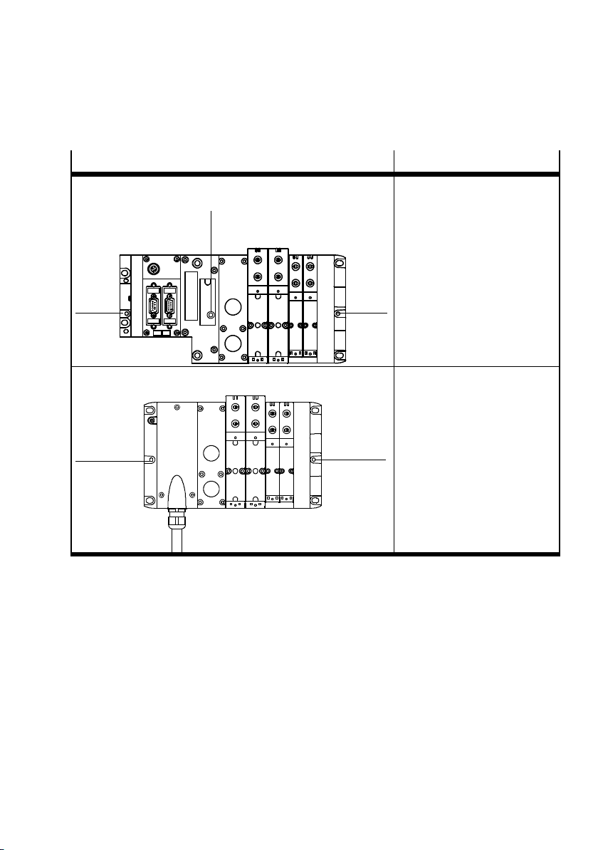
2. Mounting
Variant Mounting option
VTSA... valve terminal with CPX terminal
1
VTSA... valve ter minal with multi-pin node
1
Tab. 2/16: Holes for H-rail clamping unit
Holes for H-rail
clamping units:
1 in the pneumatic interface
under the inscription label
2 in the end plates
22
Holes for H-rail
clamping units:
1 in the multi-pin node
2 in the right end plate
2
Mounting Proceed as follows:
1. Make sure the mounting surface can support the valve
terminal (weights Appendix A, Tab. A/2).
2. Mount the H-rail (DIN mounting rail EN 60715 - 35x7.5;
width 35 mm, height 7.5 mm). Make sure there is sufficient space for connecting the power supply cables and
tubing.
3. Fasten the H-rail to the mounting surface at intervals of
approx. every 100 mm.
Festo P.BE-VTSA-44-EN en 1202g
2-7
Page 80
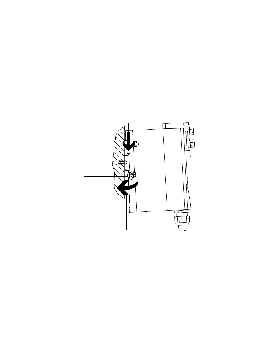
2. Mounting
1
H-rail
2
Retaining screw
of the H-rail
clamping unit
3
Clamping
component of the
H-rail clamping
unit
4. Mount the H-rail clamping units ( Tab. 2/16)
5. Hang the valve terminal on the H-rail ( Fig. 2/1,
arrow (A)).
6. Swing the valve terminal onto the H-rail ( Fig. 2/1,
arrow (B)). Make sure that the clamping component is
horizontal to the H-rail.
(A)
3
1
2
(B)
Fig. 2/1: Mounting the VTSA... valve terminal on an H-rail
7. Secure the VTSA... valve terminal, as with the CPX terminal, against tilting or sliding by tightening the retaining
screw with 1.3 Nm.
2-8
Festo P.BE-VTSA-44-EN en 1202g
Page 81
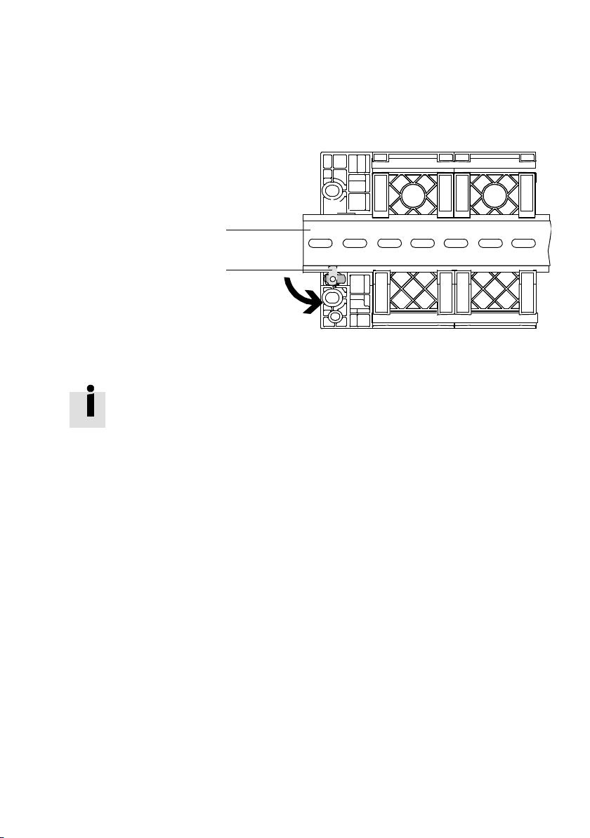
2. Mounting
1
H-rail
2
Clamping
component of the
H-rail clamping
unit
1
2
Fig. 2/2: Rear view: example for H-rail mounting of the CPX terminal
Further information for H-rail mounting of the VTSA... valve
terminal with CPX terminal can be found in the CPX system
description.
Dismounting Proceed as follows:
1. Remove the safety screw from the H-rail clamping unit
(position of screws Tab. 2/16). Make sure that the
clamping component is horizontal to the H-rail.
2. Swing the VTSA... valve terminal forwards from the H-rail
( Fig. 2/3, arrow (B)).
3. Lift the valve terminal from the H-rail ( Fig. 2/3,
arrow (A)).
Festo P.BE-VTSA-44-EN en 1202g
2-9
Page 82
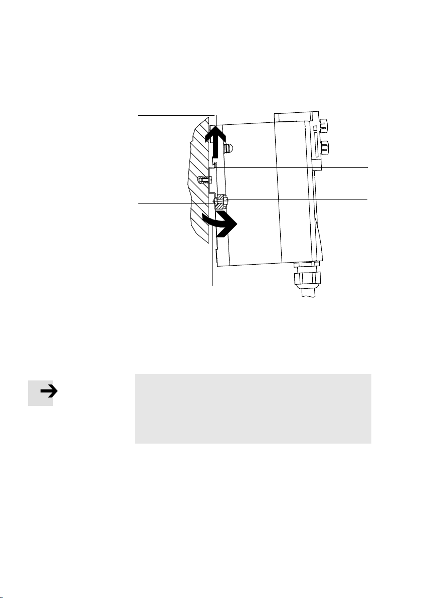
2. Mounting
1
H-rail
2
Retaining screw
of the H-rail
clamping unit
3
Clamping
component of the
H-rail clamping
unit
Fig. 2/3: Dismounting the VTSA... valve terminal from the H-rail
(A)
3
(B)
1
2
2.2.2 Mounting/dismounting on walls
Note
Mounting on uneven, flexible surfaces can result in damage to the VTSA... valve terminal.
•
Mount the VTSA... valve terminal only onto an even, torsionally rigid surface.
2-10
Festo P.BE-VTSA-44-EN en 1202g
Page 83

2. Mounting
Caution
Overloading the mounting holes, bending the VTSA... valve
terminal with CPX terminal or internal vibrations can cause
damage.
•
In such cases use the additional mounts for the CPX
terminal ( information in the CPX system description).
•
VTSA (width 18 ... 52 mm) with metal CPX interlinking
block:
On every fourth VTSA component (manifold sub-base or
supply plate), use the mounting bracket type:
VAME-S6-W-M46. The manifold sub-bases and
pneumatic supply plates have corresponding threaded
holes (tightening torque 3.0 Nm) for mounting the
brackets.
•
AllotherVTSAunitsinwidth18...52mm:
Additional mounting brackets of type VAME-S6-10-W are
to be used depending on the number of valve positions
( Appendix A, Tab. A/5). The manifold sub-bases and
pneumatic supply plates have corresponding threaded
holes (tightening torque 3.0 Nm) for mounting the brackets.
•
AllotherVTSAunitsinwidth65mm:
Use the mounting holes in at least every second manifold sub-base.
Festo P.BE-VTSA-44-EN en 1202g
The following components contain holes for wall mounting
( Tab. 2/17).
– End plates
– Pneumatic interface
– Multi-pin node
– Manifold sub-bases, width 65 mm
2-11
Page 84
2. Mounting
Mounting Proceed as follows:
1. Make sure the mounting surface is flat and that it can
support the VTSA... valve terminal (weights
Appendix A, Tab. A/2).
Make sure there is sufficient space for connecting the power
supply cables and tubing.
2. Drill mounting holes in the mounting surface.
3. Secure the valve terminal to the mounting surface using
screws of the appropriate length ( Tab. 2/17).
2-12
Festo P.BE-VTSA-44-EN en 1202g
Page 85
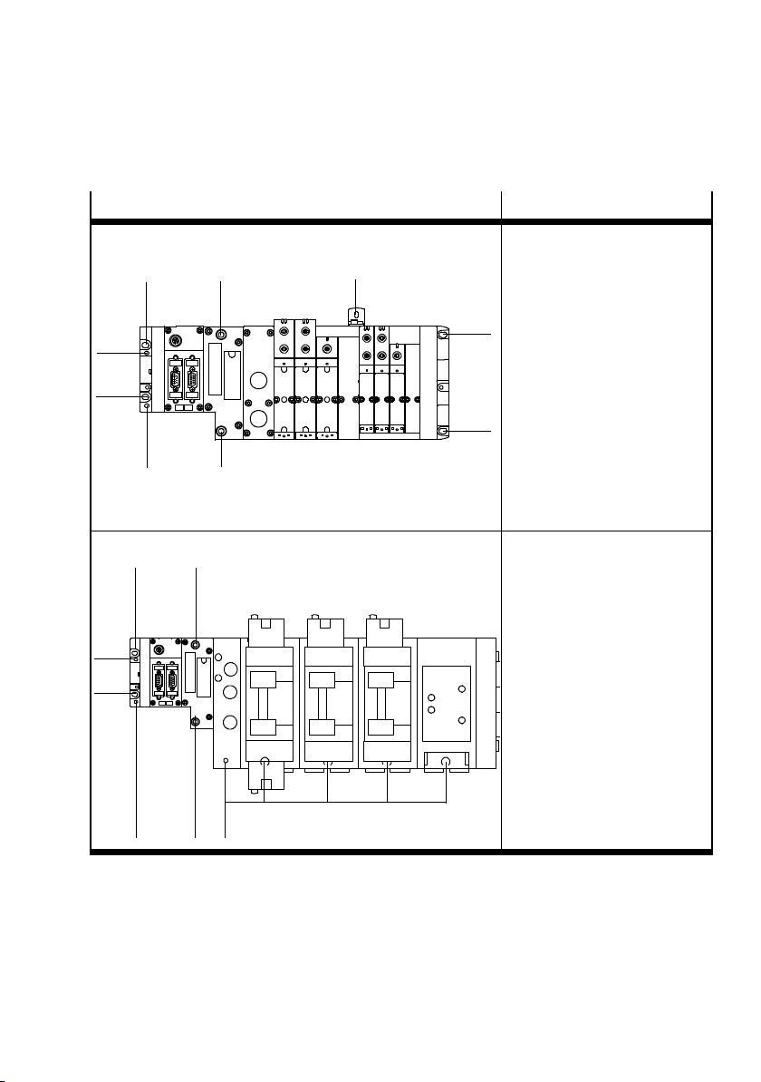
2. Mounting
V
)
w
Variant Mounting option
Valve terminal VTSA... (Width 18 ... 52 mm) withCPX-Terminal
1
1
3
2
1
2
alve terminalVTSA...(width 65 mm
1
1
1
ith CPXterminal
3
1
– End plates: 2 x M6 screws
each (alternatively 2 x M4
screws for the left end plate)
– Pneumatic interface (CPX):
twoM6screws,internal
1
hexagon socket
– optional angle bracket on the
pneumatic supply plate or
manifold sub-base:
type VAME-S6-10-W:
one M5 screw
type VAME-S6-W-M46:
one M4 or M6 screw
1
1 Hole for M6 screw
2 Hole for M4 screw
3 Hole in bracket for M5
or M4/M6 screw
– Left end plate:
2 x M6 screws (alternatively 2
xM4screws)
– Pneumatic interface (CPX):
twoM6screws,internal
hexagon socket
– Manifold sub-bases and ad-
apters:
M10 screw for each
1 Hole for M6 screw
2 Hole for M10 screw
3 Hole for M4 screw
If necessary, use the following
additional mounting options:
– Holes (blind holes) on the
1
Festo P.BE-VTSA-44-EN en 1202g
23
rear of the manifold subbases for M8 thread.
2-13
Page 86
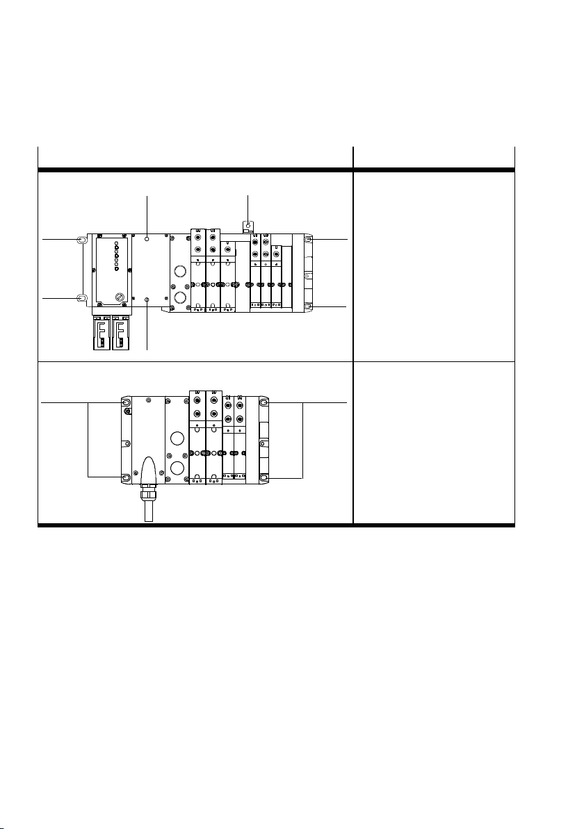
2. Mounting
Variant Mounting option
VTSA...valveterminalwithtype03electronics
1
1
1
2
– End plates: 2 x M6 screws
each
– Pneumatic interface (type
03):
1
twoM6screws,internal
hexagon socket
– optional angle bracket on the
pneumatic supply plate or
manifold sub-base:
one M5 screw
1 Hole for M6 screw
1
2 Hole for M5 screw in bracket
1
VTSA... valve ter minal with multi-pin node
11
Tab. 2/17: Options for mounting the VTSA... valve terminal on a wall
– Multi-pin node:
twoM6screws
– Right end plate:
twoM6screws
1 Hole for M6 screw
2-14
Rear mounting for width 65 mm
Holes (blind holes also see following drawing) for securing
the terminal to machines or metal frames can be found on the
rear of the manifold sub-bases (rear mounting). M8 threads
need to be cut for this purpose. All of the steps for wall
mounting described above are also applicable here.
Festo P.BE-VTSA-44-EN en 1202g
Page 87
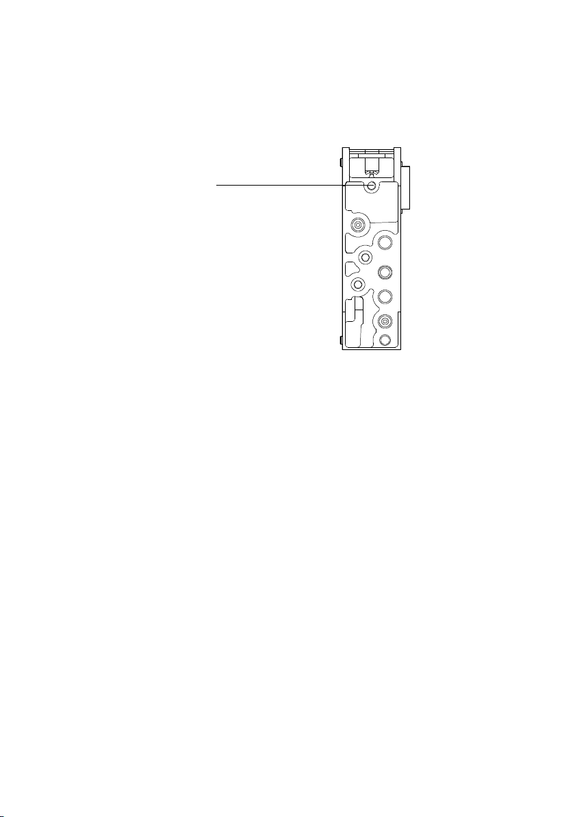
2. Mounting
1
Blind hole
without M8
thread
1
Fig. 2/4: Blind hole in manifold sub-base for rear mounting
Dismounting Proceed as follows:
1. Secure a mounted hanging valve terminal VTSA... from
falling down before you loosen it from the mounting surface.
Festo P.BE-VTSA-44-EN en 1202g
2. Loosen the mounting screws ( Tab. 2/17).
3. Remove the valve terminal from the mounting surface.
2-15
Page 88
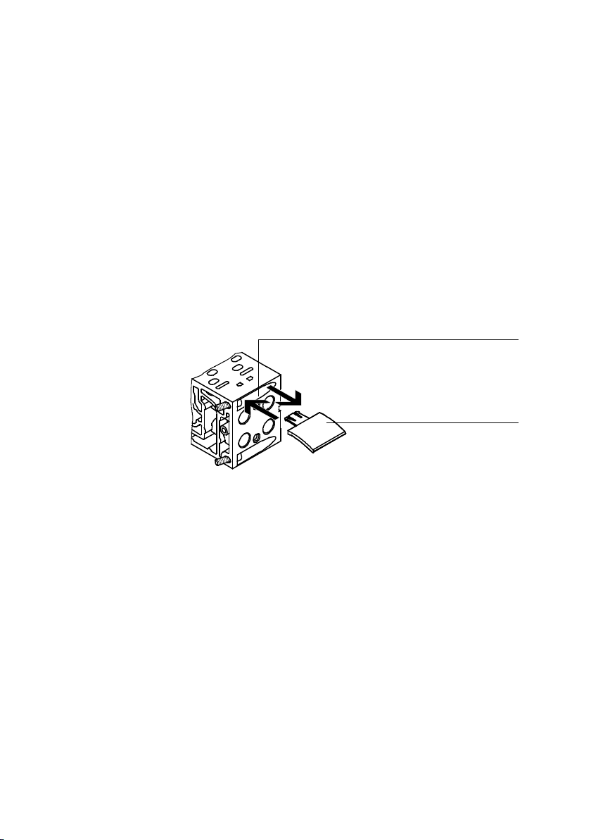
2. Mounting
2.3 Mounting/dismounting the optional inscription label holder, width 18 ... 52 mm
An inscription label holder can be mounted onto each manifold sub-base to label the valves or working lines.
Mounting Clip the inscription label holders into the recesses in the man-
ifold sub-bases ( image)
Dismounting Pull the inscription label holder from the manifold sub-base.
1
Fixture for inscription label
holder on the
manifold subbase
2
Inscription label
holder
1
2
Fig. 2/5: Mounting the inscription label holder
2-16
Festo P.BE-VTSA-44-EN en 1202g
Page 89
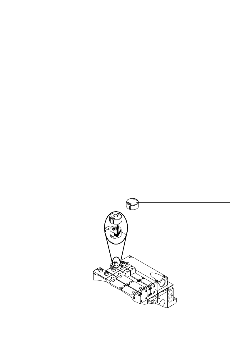
2. Mounting
2.4 Mounting/dismounting the optional manual override cover caps, width 18 ... 52 mm
You can modify the function of the manual overrides with
cover caps.
Cover cap, covered This cover cap can be used to prevent unintentional operation
of the manual overrides.
Cover cap, non-detenting The detenting/non-detenting function of the manual override
can be changed to just a non-detenting function by mounting
this cover cap in a manual override.
Mounting Proceed as follows:
1. Make sure that the relevant manual overrides are in a
unactuated state. If necessary, set detenting manual overrides in the initial position ( Tab. 4 / 7).
2. Clip the cover caps into the recesses in the manual overrides ( image)
1
Manual override
cover cap
(manual override
without function)
2
Manual override
cover cap
(manual override
non-detenting
only)
3
Manual override
(MO)
Fig. 2/6: Mounting the manual override cover caps
Festo P.BE-VTSA-44-EN en 1202g
1
2
3
2-17
Page 90
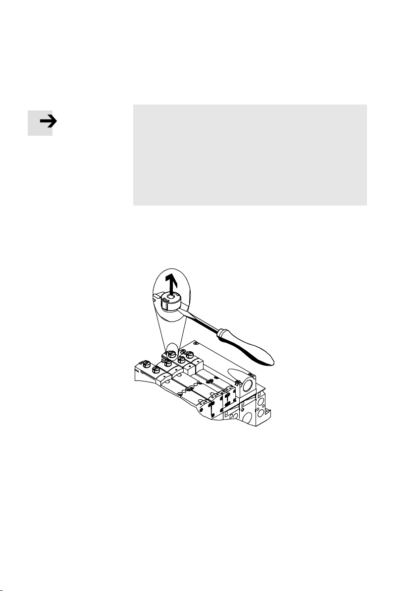
2. Mounting
Note
The manual override cover caps are used to limit the function of the manual override ( cover cap description) and
are designed in such a way that they can only be removed
with an increased exertion of force.
If you wish to remove the cover caps, note that the snap
hook of the cover caps may become damaged when the
hooks are dismantled.
Dismounting Proceed as follows:
•
Pry the caps from the manual override by using a suitable
screwdriver ( image):
2-18
Fig. 2/7: Dismounting the manual override caps
Festo P.BE-VTSA-44-EN en 1202g
Page 91

Installation
Chapter 3
Installation
Festo P.BE-VTSA-44-EN en 1202g
3-1
Page 92

3. Installation
Contents
3. Installation 3-1...................................................
3.1 Compressed air preparation 3-4......................................
3.1.1 Operation with unlubricated compressed air 3-4.................
3.1.2 Operation with lubricated compressed air 3-4....................
3.2 General notes on connecting the tubing 3-7.............................
3.2.1 Installing the tubing 3-8.....................................
3.3 Connecting the VTSA... valve terminal 3-12..............................
3.4 Pilot control, width 18 ... 52 mm 3-12...................................
3.4.1 Venting pilot exhaust air 3-12..................................
3.4.2 Pilot air supply 3-13..........................................
3.5 Pilot control, width 65 mm 3-19........................................
3.5.1 Pilot air supply 3-19..........................................
3.6 Pressure zone separation, width 18 ... 52 mm 3-23........................
3.7 Pressure zone separation, width 65 mm 3-26.............................
3.8 Reversibly operated VTSA... valve terminal 3-27..........................
3.8.1 Operating the VTSA... valve terminal with reversible valves 3-28......
3.8.2 Operating the VTSA... valve terminal with reversible pressure
regulating valves 3-29........................................
3.8.3 Setting the pressure regulating valve 3-30.......................
3.9 Vacuum / low-pressure operation: 3-36.................................
3.10 Connecting the pneumatic lines 3-38...................................
3.11 Connecting the electric cables 3-49.....................................
3.12 Address assignment of the valves 3-53..................................
3-2
Festo P.BE-VTSA-44-EN en 1202g
Page 93

3. Installation
Contents of this chapter This chapter describes the tubing and cabling of the VTSA...
valve terminal. This includes in particular the following:
– General instructions on compressed air preparation and
tubing connections
– Instructions on pilot control with internal or external pilot
air supply
– Instructions on operating the valve terminals with pres-
sure zones
– Instructions on operating the valve terminal with revers-
ible 2x3/2-way valves
– Fitting the QS threaded connectors
– Connecting the power supply
– Earthing the valve terminal
– Address assignment of the valves
Additional information Instructions on connecting the electrical components of the
VTSA... valve terminal with multi-pin node can be found in
the relevant information supplied with the product.
Requirements for observing the certified UL conditions if the
product is operated in the USA or Canada can be found in the
separate special UL-specific documentation.
Instructions on connecting the operating voltage for the
VTSA... valve terminal with CPX terminal can be found in the
CPX system description, chapter 3.
Detailed instructions on how to connect CPX modules (bus
nodes, I/O modules, etc.) can be found in the corresponding
CPX module descriptions. Detailed instructions for connecting
type 03 modules (bus nodes, I/O modules) can be found in
the corresponding descriptions for the type 03 module.
Festo P.BE-VTSA-44-EN en 1202g
3-3
Page 94
3. Installation
3.1 Compressed air preparation
Caution
Unfiltered or incorrectly lubricated compressed air will
reduce the service life of the valve terminal.
3.1.1 Operation with unlubricated compressed air
Note
Too much residual oil content in the compressed air will
reduce the service life of the valve terminal.
– When using bio-oils (oils that are based on synthetic
ester or native ester, e.g. rapeseed oil methyl ester), the
maximum residual oil content of 0.1 mg/m
be exceeded ( ISO 8573-1-2010 class 2).
– When using mineral oils (e.g. HLP oils to DIN 51524 Part
1 to 3) or corresponding oils based on polyalphaolefin
(PAO), the maximum residual oil content of 5 mg/m
should not be exceeded
( ISO 8573-1-2010 class 4).
This avoids operative malfunction of the valves.
3
should not
3
Excessive residual oil is not permissible irrespective of the
compressor oil, as otherwise the basic lubrication will be
washed out with time.
3.1.2 Operation with lubricated compressed air
Operate system equipment with unlubricated compressed air
if possible. This is better for the environment. Festo pneumatic valves and actuators have been designed so that, if used as
intended, they will not require additional lubrication and will
still achieve a long service life.
3-4
Festo P.BE-VTSA-44-EN en 1202g
Page 95
3. Installation
Caution
Operation with lubricated compressed air will cause the
life-time lubrication, which is necessary for unlubricated
operation, to be “washed out”.
Note the following instructions if lubricated compressed air
must be used.
The compressed air produced after the compressor must
comply with the quality of unlubricated compressed air. If
possible, do not operate all of your equipment with lubricated
compressed air. If possible, always install the lubricators directly upstream of the consuming actuator.
Caution
Incorrect additional oil and too much residual oil content in
the compressed air will reduce the service life of the valve
terminal.
– Use Festo special oil OFSW-32 or the alternatives listed
in the Festo catalogue (as per DIN 51524-HLP32, basic
viscosity 32 CST at 40 °C).
– The additional lubrication must not exceed 25 mg/m
3
(ISO 8573-1 class 5).
– Check the correct lubricator setting ( following sec-
tion)
This avoids operative malfunction of the valves.
Setting the lubricator 0.2 to max. 1 drop/min. or 0.5 to 5 drops/1000 l of air when
the machine is running (typical operating status).
Checking the setting The procedure described below can be used to check the
lubricator setting.
Proceed as follows:
•
Check the service units for condensate and lubricator
setting twice a week.
1. Ascertain the actuator which is furthest from the
lubricator.
Festo P.BE-VTSA-44-EN en 1202g
3-5
Page 96

3. Installation
2. Ascertain the valve terminal which controls this cylinder.
3. Remove the silencer, if fitted, from port (3/5).
4. Hold a piece of white cardboard 10 cm in front of the exhaust port.
5. Let the system run for a short period.
– There must be only a slight yellow colouring on the
cardboard. If oil droplets appear, this is an indication
that too much oil has been used.
Another indicator of over-lubrication is the coloration or the
condition of the exhaust air silencer. A distinctly yellow colouring of the filter element or drops of oil on the silencer indicate that the lubricator setting is too high.
3-6
Festo P.BE-VTSA-44-EN en 1202g
Page 97
3. Installation
3.2 General notes on connecting the tubing
Warning
Uncontrolled movements of the connected actuators and
loose tubing can cause injury to persons and/or damage
to property.
Before carrying out mounting, installation and maintenance work, switch off the following:
– Compressed air supply
– Operating and load voltage supplies.
Note
Observe the following if the UL requirements are to be
complied with in your application:
– Rules for observing the UL certification can be found in
the separate UL-specific documentation. The relevant
technical specifications listed there also apply here.
– The technical data in this documentation may show val-
ues deviating from this.
Pleasenotethefollowing:
The components of the valve terminals contain electrostatically sensitive components. The components will be damaged
if you touch the contact surfaces of the plug connectors or if
you do not observe the handling specifications for electrostatically sensitive devices.
Back pressure When exhausting large volume actuators or if the exhaust
performance is too small, back pressures can build up in the
valve terminal exhaust ducts. The back pressures can lead to
pneumatic actuation of other valves, especially with unswitched 3/2-way valves that are normally closed.
Festo P.BE-VTSA-44-EN en 1202g
3-7
Page 98
3. Installation
To avoid back pressures:
•
Optimise the pressurisation and ventilation capacity of
the valve terminal, for example, by using larger diameter
tubing or an additional compressed air supply via pneumatic supply plates with venting via a silencer or exhaust
plate.
•
Separate the exhaust ducts, if necessary, by using pressure zones ( section 1.2.5).
3.2.1 Installing the tubing
If elbow connectors or multiple distributors are used, the air
flow will be reduced slightly.
Connection Proceed as follows:
1. Push the tubing as far as possible into or over the tube
coupling of the fitting.
3-8
2. Depending on connection:
– If necessary, pull the locking ring 1 over the tube
coupling ( Fig. 3/1).
– Tighten the clamping screw 2 ( Fig. 3/1).
– For the right end plate, size 2:
First mount the tubing at port (1) and then at ports (3)
and (5).
Securethetubingwithahoseclamp3
3. For a better overview of the system group the tubing together with:
- tubing straps or
- multi-tube holders
Festo P.BE-VTSA-44-EN en 1202g
Page 99
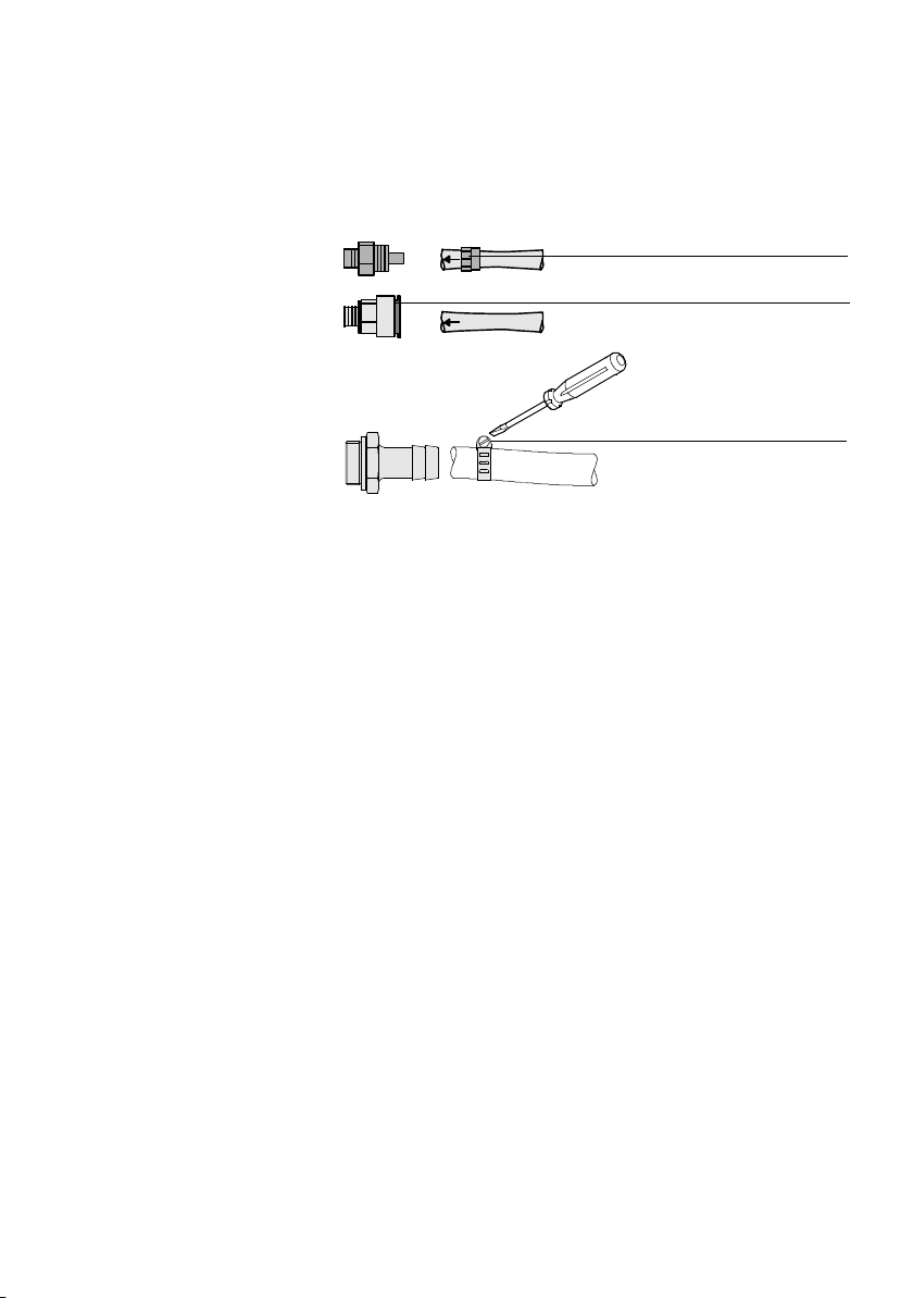
3. Installation
2
1
3
Fig. 3/1: Mounting the tubing connections
Festo P.BE-VTSA-44-EN en 1202g
3-9
Page 100

3. Installation
Disconnection Proceed as follows:
Warning
If the pneumatic tubing is under pressure when dismounted, it may perform sudden unexpected movements, causing injury to persons. Carry out the following steps before
disconnecting the pneumatic tubing on the valve terminal:
•
Deactivate compressed air supply.
•
Make sure that all pneumatic tubing is unpressurized.
•
Exhaust all actuators controlled by valves that are
blocked in the neutral or middle positions.
1. Mark all pneumatic tubing.
2. Depending on connection:
– Press down the locking ring of the threaded connector
1, e.g. with a Festo QSO releasing tool.
3-10
– Loosen the clamping screw 2 of the threaded con-
nector.
– Loosen the hose clamp screw 3.
3. Remove the tubing from the threaded connector.
4. Seal threaded connectors that are not required with
blanking plugs 4.
Festo P.BE-VTSA-44-EN en 1202g
 Loading...