

Page 1
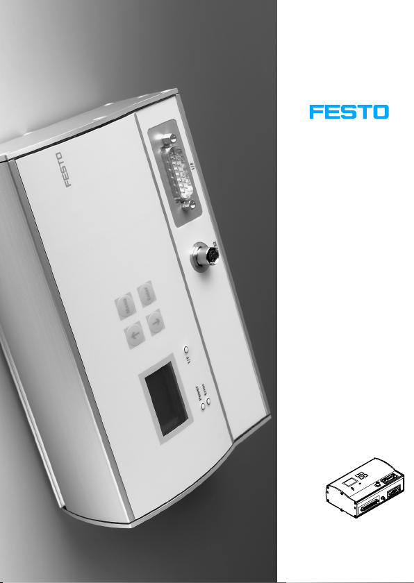
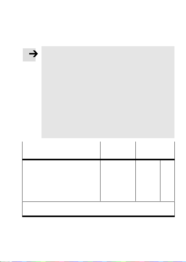
Motor controller SFC−LAC
Kurzübersicht
Brief overview
Motorcontroller
Typ
SFC−LAC−...−IO
Motor controller
type
SFC−LAC−...−IO
Deutsch
English
Español
Français
Italiano
Svenska
686 710
0604NH
Page 2

Deutsch 3 . . . . . . . . . . . . . . . . . . . . . . . . . . . . . . . . . . . . . . . . . . .
English 15 . . . . . . . . . . . . . . . . . . . . . . . . . . . . . . . . . . . . . . . . . . . .
Español 27 . . . . . . . . . . .
. . . . . . . . . . . . . . . . . . . . . . . . . . . . . . . .
Français 39 . . . . . . . . . . . . . . . . . . . . . . . . . . . . . . . . . . . . . . . . . . .
Italiano 51 . . . . . . . . . . . . . . . . . . . . . . . . . . . . . . . . . . . . . . . . . . . .
Svenska 63 . . . . . . . . . . . . . . . . . . . . . . . . . . . . . .
Edition:
0604NH
. . . . . . . . . . . . .
Original: de
© (Festo AG&Co.KG, D73726 Esslingen, Germany, 2006)
Internet: http://www.festo.com
E−Mail: [email protected]
Festo P.BE−K−SFC−LAC−IO 0604NH 2
Page 3
1 BenutzerhinweiseDeutsch
Hinweis
Diese Kurzübersicht ist Bestandteil des Dokumen
tationspaketes Typ P.BE−SFC−LAC−UDOK. Sie dient nur
zur Erstinformation und ersetzt nicht die vollständige
Dokumentation, die als PDF−Datei auf der mitgeliefer
ten CD−ROM des Dokumentationspaketes enthalten ist
(siehe Tabelle).
S Beachten Sie unbedingt die Informationen und
sicherheitstechnischen Hinweise in der vollständigen
Beschreibung des Motorcontrollers.
S Bitte wenden Sie sich bei technischen
Ihren lokalen Festo−Service oder an folgende E−Mail−
Adresse: [email protected]
Problemen an
Inhalt der CD−ROM
Beschreibung des Motorcontrollers
TypSFC−LAC−...−IO
Installation und Inbetriebnahme
Steuerungsschnittstelle (E/A)
usw.
1)
= <Teilenummer> + <Sprachkennung>. Unter dieser Teilenummer auch
als Papierversion erhältlich.
Festo P.BE−K−SFC−LAC−IO 0604NH Deutsch 3
Sprache Dateiname
Deutsch
Englisch
Spanisch
Französisch
Italienisch
Schwedisch
540547
540548
540549
540550
540551
540552
1)
d1
g1
e1
f1
i1
s1
Page 4

Weitere Informationen finden Sie:
im Hilfesystem der Konfigurationssoftware Festo
Configuration Tool (FCT):
FCT−Help: Funktionsbeschreibung FCT
SFC−LAC−Help: Inbetriebnahme SFC−LAC
in der der jeweiligen Komponente beiliegenden
Bedienungsanleitung, z.B. für HME−...
Bestimmungsgemäße Verwendung
Der Motorcontroller SFC−LAC dient als Positioniersteuerung
und Lageregler für das Linearmodul HME.
Die übergeordnete SPS/IPC wird beim Typ SFC−LAC−...−IO
über digitale Ein−/Ausgänge angeschlossen.
Inbetriebnahme und Parametrierung der Verfahrsätze
erfolgen:
dem Software−Paket FCT und dem PlugIn SFC−LAC
mit
über die RS232−Schnittstelle oder
beim Typ SFC−LAC−...−H2−... optional mit dem Bedien
feld (Display und 4 Bedientasten).
Festo P.BE−K−SFC−LAC−IO 0604NH Deutsch4
Page 5
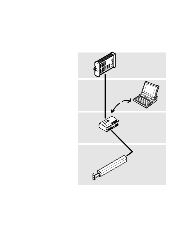
1 Übergeordnete
Steuerung, z.B.
Festo Typ FEC...
2 Software−Ebene:
Festo Configuration
Tool
3 Controller−Ebene:
SFC−LAC
4 Motor−Antriebs
ebene: HME−...
1
2
3
4
Festo P.BE−K−SFC−LAC−IO 0604NH Deutsch 5
Page 6
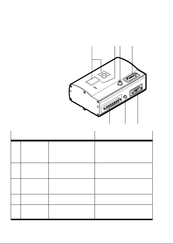
2 Anzeige− und Anschlusselemente
1 Bedienfeld (nur Typ
SFC−LAC−...−H2−...)
12 4
2 LEDs
3 Parametrierung
4 Steuerung
(SPS/IPC)
5 Spannungs
versorgung
6 Erdung (FE)
7 HME−...
Anschluss am SFC−LAC−...−I0 Beschreibung
Parametrie
3
rung
Steuerung Sub−D, 15−polig
4
Spannungs
5
versorgung
Erdung Stehbolzen M4 Funktionserde (FE)
6
HME−... Sub−D, 24W7
7
M8, 4−polig
Buchse
Stecker
Sub−D, 7W2
Stecker
Buchse
RS232−Schnittstelle zur
Parametrierung, Inbetrieb
nahme und Diagnose
Schnittstelle zum Anschluss
an eine SPS−Steuerung
Spannungsversorgungs
anschluss
Schnittstelle zur HM E−...
3
567
Festo P.BE−K−SFC−LAC−IO 0604NH Deutsch6
Page 7
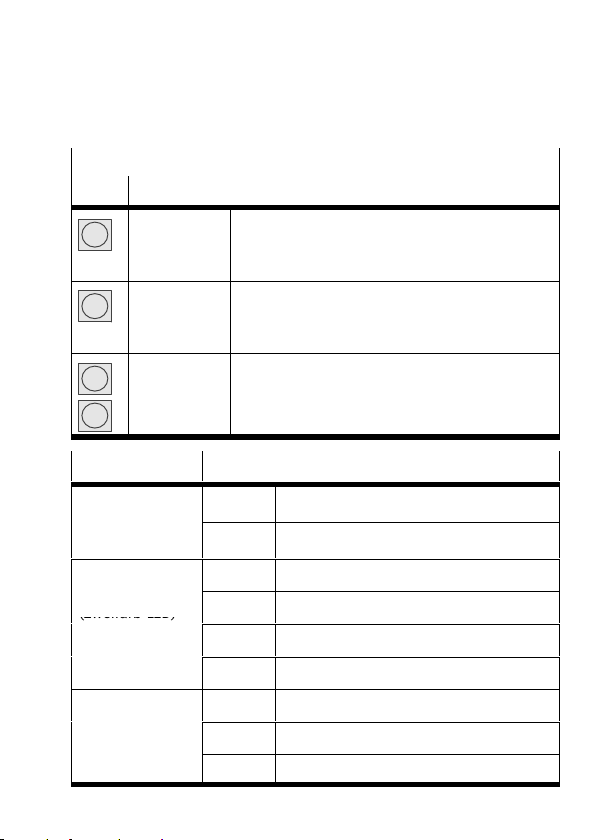
1 Bedienfeld (nur Typ SFC−LAC−...−H2−...)
B
(Zweifarb LED)
Taste Funktion
Menu
Enter
v
V
2 LED Zustand
Power
etriebs−
spannung
I/F
Positionierstatus
(Zweifarb−LED)
Error
Fehleranzeige
Festo P.BE−K−SFC−LAC−IO 0604NH Deutsch 7
MENU
ESC
EMERG.STOP
OK
SAVE
START/STOP
{ }
EDIT
Statusanzeige > Hauptmenü
Eingabe verwerfen oder Menüebene zurück
Aktuellen Positioniervorgang abbrechen
Bestätigt Auswahl bzw. Eingabe
Speichert Parametereinstellungen dauerhaft
Startet/stoppt Demo−Modus
Vorheriger/nächster Menübefehl oder
manuell verfahren (Teachen)
Vergrößert/verkleinert Parameterwert
grün Betriebsspannung liegt an
aus Keine Betriebsspannung
grün Betriebsbereit, Freigabe liegt vor
grün/rot Betriebsbereit, Freigabe fehlt
aus Positionierbetrieb oder Fehler/Warnung
rot Regler−Endstufe aus
rot Fehler
blinkt Warnung
aus Kein interner Fehler gemeldet
Page 8
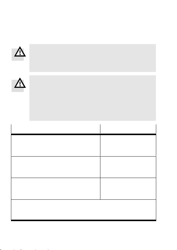
3 Hinweise zur Montage und Installation
Warnung
Schalten Sie vor Montage−, Installations− und
Wartungsarbeiten die Betriebsspannungsversorgung
der Elektronik aus.
Warnung
Bei Einbau der Achse in schräger und senkrechter Lage
möglicherweise herunterschlagende Massen!
S Prüfen Sie, ob externe Sicherungsmaßnahmen erfor
derlich sind (z.B. Zahnklinken oder bewegte Bolzen).
Damit vermeiden Sie bei Stromunterbrechungen ein
plötzliches Abwärtsgleiten der Arbeitsmasse.
*)
Spannungsversorgung
Lastversorgung
Nennstrom (max. Dauerstrom)
Spitzenstrom
Logikversorgung
Nennstrom / Spitzenstrom
Interne Sicherung
**)
**)
Wert
48 VDC +5% / −10%
10 A
20 A
24 VDC ±10%
0,4 A / 0,8 A
2,5A superflink
E/A−Versorgung
Leerlaufstrom / Spitzenstrom
(je Ausgang max. 0,5 A)
*)
Die Toleranzen für die Spannungsversorgungen müssen auch
direkt an den Anschlüssen des SFC−LAC eingehalten werden.
**)
Massen verbinden für gleiches Bezugspotenzial !
24 VDC ±10%
0,05 A / 2,1 A
Festo P.BE−K−SFC−LAC−IO 0604NH Deutsch8
Page 9
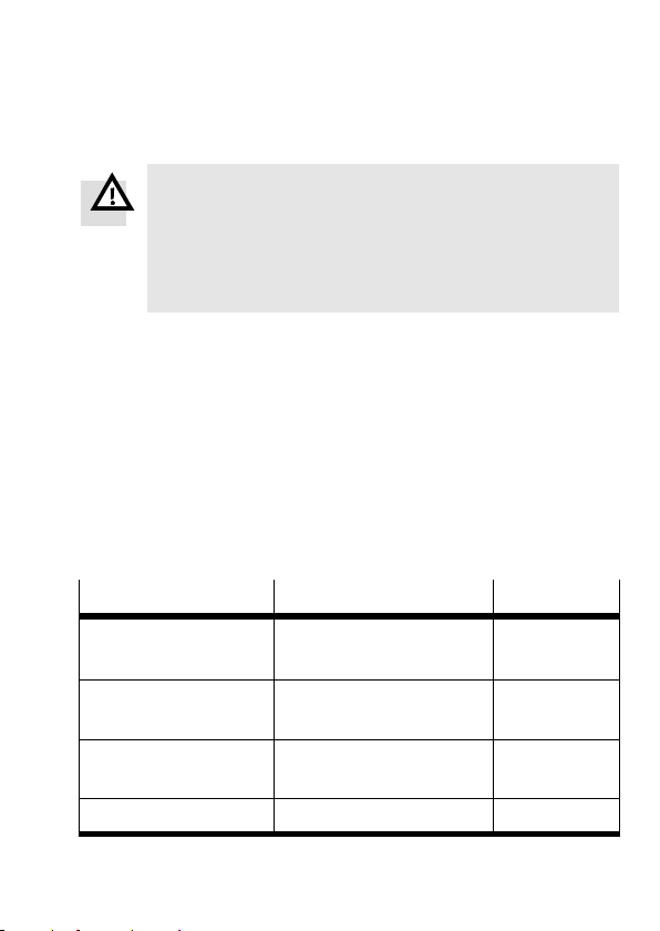
Warnung
Verwenden Sie ausschließlich Stromquellen, die eine
sichere elektrische Trennung der Betriebsspannung
nach IEC/DIN EN 60204−1 gewährleisten. Berücksichti
gen Sie zusätzlich die allgemeinen Anforderungen an
PELV−Stromkreise gemäß IEC/DIN EN 60204−1.
S Geregeltes Netzteil verwenden.
S Zur Vermeidung elektrostatischer Entladungen und
Einhaltung der Schutzart IP54: Nicht verwendete
Anschlüsse mit den mitgelieferten Schutzkappen
verschließen.
S Zur Vermeidung von Masseschleifen: Nur
einen der
Erdungsanschlüsse verwenden (z.B. 6).
S Verwenden Sie ausschließlich diese Kabel (max. Länge
beachten):
Kabel
Versorgungskabel (VDC) KPWR−MC−1−SUB−15HC−... 2,5 / 5 / 10
Motorkabel (HME) KMTR−LAC−S50HC−S50HC−... 2,5 / 5 / 10
Steuerkabel (SPS) KES−MC−1−SUB−15−... 2,5 / 5 / 10
Programmierkabel (PC) KDI−MC−M8−SUB−9−... 2,5
Festo P.BE−K−SFC−LAC−IO 0604NH Deutsch 9
Zubehör Typ ... Länge [m]
(max. 10 m)
(max. 10 m)
(max. 30 m)
Page 10

4 Hinweise zu Inbetriebnahme und Betrieb
Warnung
Elektrische Achsen können mit großer Kraft und
Geschwindigkeit verfahren. Kollisionen können zu
schweren Verletzungen oder zur Zerstörung von
Bauteilen führen.
S Stellen Sie sicher, dass niemand in den Einfluss−
bereich der Achsen sowie anderer angeschlossener
Aktoren greifen kann und sich keine Gegenstände im
Verfahrbereich befinden, solange das System an
Energiequellen angeschlossen ist.
Warnung
Verletzungsgefahr.
Fehler bei der Parametrierung können Personen− und
Sachschäden verursachen. Zur korrekten Einstellung
der Bezugspunkte und des Arbeitsbereiches muss in
folgenden Fällen zwingend eine Referenzfahrt
vorgenommen werden:
bei der Erstinbetriebnahme,
nach Änderung der Referenzierungsmethode,
nach Änderung des Achsennullpunktes,
nach jedem Einschalten der Logikspannungs
versorgung!
S Vollziehen Sie die Inbetriebnahme mit dem Festo
Configuration Tool (siehe FCT−Hilfesystem) oder
dem Bedienfeld (nur Typ SFC−LAC−...−H2).
Festo P.BE−K−SFC−LAC−IO 0604NH Deutsch10
mit
Page 11

Überblick zur Erstinbetriebnahme mit Bedienfeld
Vor dem Einschalten: Sicherstellen, dass an der
1.
Steuerungsschnittstelle (SPS) kein ENABLE anliegt.
2. SFC−LAC einschalten; Antriebstyp auswählen
(z.B.HME−16−200).
3. Parameter für Referenzfahrt einstellen: Methode und
Geschwindigkeiten.
4. Steuerungsfreigabe für Bedienfeld setzen: [HMI = on].
Nun wird für einige Sekunden der Kommutierungspunkt
gesucht (HME vibriert).
5. Referenzfahrt durchführen.
6. Achsparameter teachen: Achsennullpunkt AZ und Software−
Endlagen (bei Änderung des AZ: erneute Referenzfahrt).
7. Verfahrsätze eingeben/teachen.
8. Probefahrt durchführen. Fahrverhalten, Bezugspunkte und
Arbeitsbereich überprüfen.
9. Bei Bedarf Verfahrsätze, Bezugspunkte und Arbeitsbereich
optimieren.
10. Funktion der Steuerungsschnittstelle testen.
11. Zum Abschluss der Inbetriebnahme die Hinweise für den
Betrieb beachten (siehe Beschreibung zum SFC−LAC−...).
Festo P.BE−K−SFC−LAC−IO 0604NH Deutsch 11
Page 12
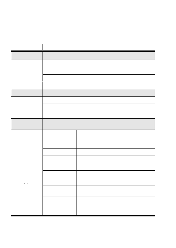
5 Menüstruktur (Bedienfeld)
gp
Menübefehl Beschreibung
Diagnostic Anzeige Systemdaten + aktuelle Einstellungen
Pos. set table Anzeige Verfahrsatztabelle
Axis param Anzeige Achsparameter und −daten
System param Anzeige Systemparameter und −daten
SW information Anzeige Betriebssystemversion (Firmware)
Positioning
Homing Start Referenzfahrt
Move posit set Start Positionierfahrt Verfahrsatz"
Demo posit tab Start Positionierfahrt Verfahrsatztabelle"
Settings
Axis type HME−... Linearmodul HME−...
Axis parameter Zero point
Homing paramet. Homing method Auswahl Referenzierungsmethode
1) 2)
Referenzfahr t und Positionierfahrten zum Test der Verfahrsätze
1)
4)
1) 2)
Auswahl des Antriebs, Parametrierung, Programmierung der
Verfahrsätze
3) 4)
Offset des Achsennullpunkts AZ vom
Referenzpunkt
SW−limit−neg
SW−limit−pos
3) 4)
Software−Endlage, negativ; bezogen auf AZ
3) 4)
Software−Endlage, positiv; bezogen auf AZ
Tool load Werkzeugmasse (z.B. Greifer)
SAVE... Parameter im EEPROM speichern
Velocity v_rp Verfahrgeschwindigkeit zum Suchen des
Velocity v_zp Verfahrgeschwindigkeit zum Anfahren des
Referenzpunkts
Achsennullpunkts
SAVE... Parameter im EEPROM speichern
4)
Festo P.BE−K−SFC−LAC−IO 0604NH Deutsch12
Page 13
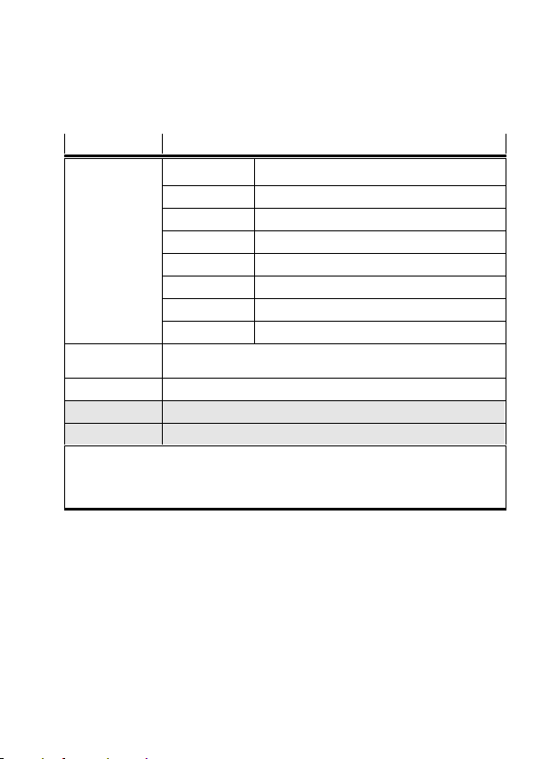
Menübefehl Beschreibung
Position set Position nr. Nummer des Verfahrsatzes (1...31)
Pos set mode Modus: absolute oder relative Positionierung
3) 4)
Position
Velocity Verfahrgeschwindigkeit
Acceleration Beschleunigung und Verzögerung
Jerk Ruck
Work load Nutzlast
SAVE... Parameter im EEPROM speichern
Jog Mode Antrieb per Pfeiltasten verfahren (auch ohne vorherige Referenz
fahrt möglich; Software−Endlagen ohne Funktion).
Password edit Einrichten eines Kennworts für das Bedienfeld
HMI control
1)
Einstellung der Gerätesteuerung über Bedienfeld
LCD adjustment Drehen der Anzeige im Display um 180°
1)
Passwort−Schutz möglich
2)
Steuerungsschnittstelle muss deaktiviert werden, siehe [HMI control]:HMI=on
3)
Teach−Betrieb
4)
Nur nach erfolgreicher Referenzfahrt
Zielposition
Festo P.BE−K−SFC−LAC−IO 0604NH Deutsch 13
Page 14

Festo P.BE−K−SFC−LAC−IO 0604NH Deutsch14
Page 15
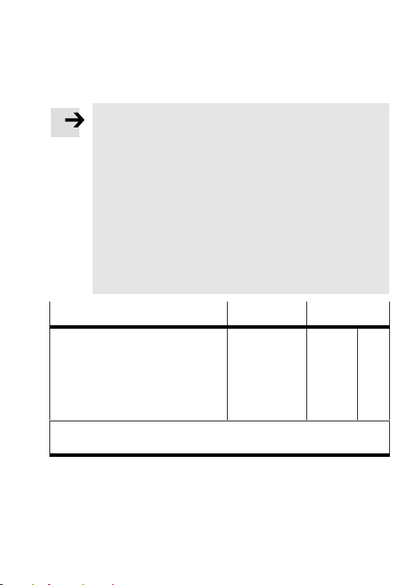
1 User instructionsEnglish
Please note
This brief overview is part of the documentation
package type P.BE−SFC−LAC−UDOK. It serves only as
initial information and does not replace the complete
documentation, which is contained as a PDF file on the
CD ROM supplied with the documentation package
(seetable).
S It is essential that you observe the information and
the safety
motor controller.
S Please consult your local Festo Service or write to the
following e−mail address if you have any technical
problems: [email protected]
instructions in the complete manual for the
Contents of the CD ROM Language File name
Manual for the motor controller
typeSFC−LAC−...−IO
Installation and commissioning
Control interface (I/O)
etc.
1)
= <part number> + <language code>.
Also available in paper version under this part number.
Festo P.BE−K−SFC−LAC−IO 0604NH English 15
German
English
Spanish
French
Italian
Swedish
540547
540548
540549
540550
540551
540552
1)
d1
g1
e1
f1
i1
s1
Page 16

Further information can be found:
in the help system of the Festo Configuration Tool
(FCT):
FCT help: description of the functions of the FCT
SFC−LAC help: commissioning the SFC−LAC
in the operating instructions supplied with the relevant
component, e.g. for HME−...
Designated use
The SFC−LAC motor controller serves as position controller
for the linear module type
HME.
With type SFC−LAC−...−IO, the higher−order PLC/IPC is
connected via digital inputs/outputs.
Commissioning and parametrizing the position sets:
with the FCT software package and the SFC−LAC PlugIn
via the RS232 interface or
with type SFC−LAC−...−H2−... optionally with the control
panel (display and four operating buttons).
Festo P.BE−K−SFC−LAC−IO 0604NH English16
Page 17
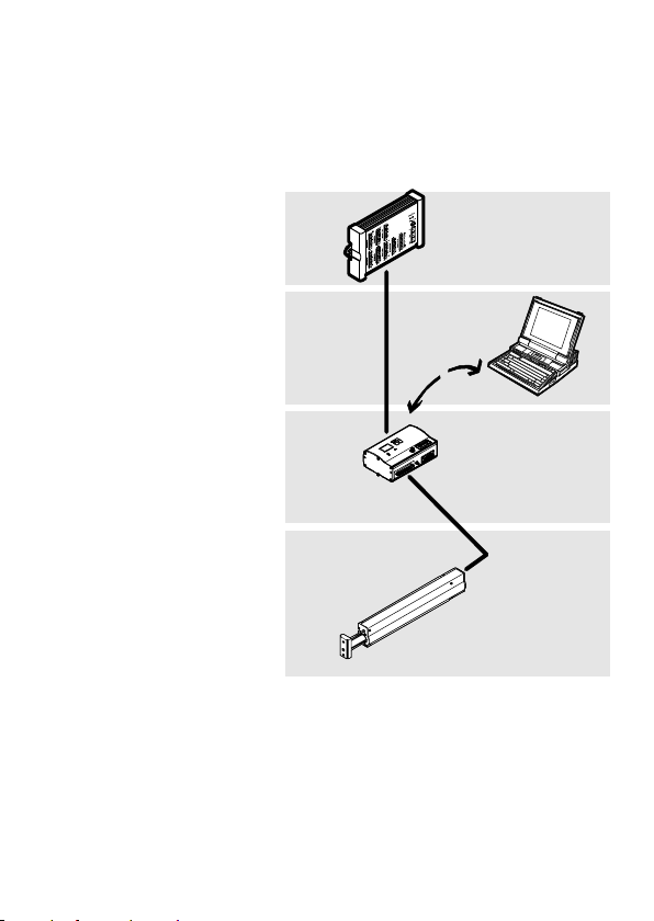
1 Higher−order
controller, e.g.
Festo type FEC...
2 Software level:
Festo Configuration
Tool
3 Controller level:
SFC−LAC
4 Motor drive level:
HME−...
1
2
3
4
Festo P.BE−K−SFC−LAC−IO 0604NH English 17
Page 18
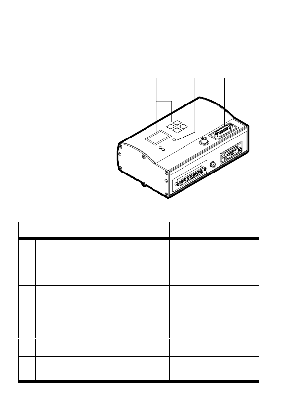
2 Display and connecting elements
1 Control panel
(only type
SFC−LAC−...−H2−...)
12 4
2 LEDs
3 Parametrizing
4 Controller (PLC/IPC)
5 Power supply
6 Earth (FE)
7 HME−...
Connection on the SFC−LAC−...−IO Description
Parametrizing M8, 4−pin
3
Controller Sub−D, 15−pin
4
Power supply Sub−D, 7W2
5
Earthing M4 stud bolt Functional earth (FE)
6
Socket
Plug
Plug
RS232 interface for
parametrizing,
commissioning and
diagnosing
Interface for connecting
to a PLC controller
Power supply connection
3
567
HME−... Sub−D, 24W7
7
Socket
Interface to HME−...
Festo P.BE−K−SFC−LAC−IO 0604NH English18
Page 19
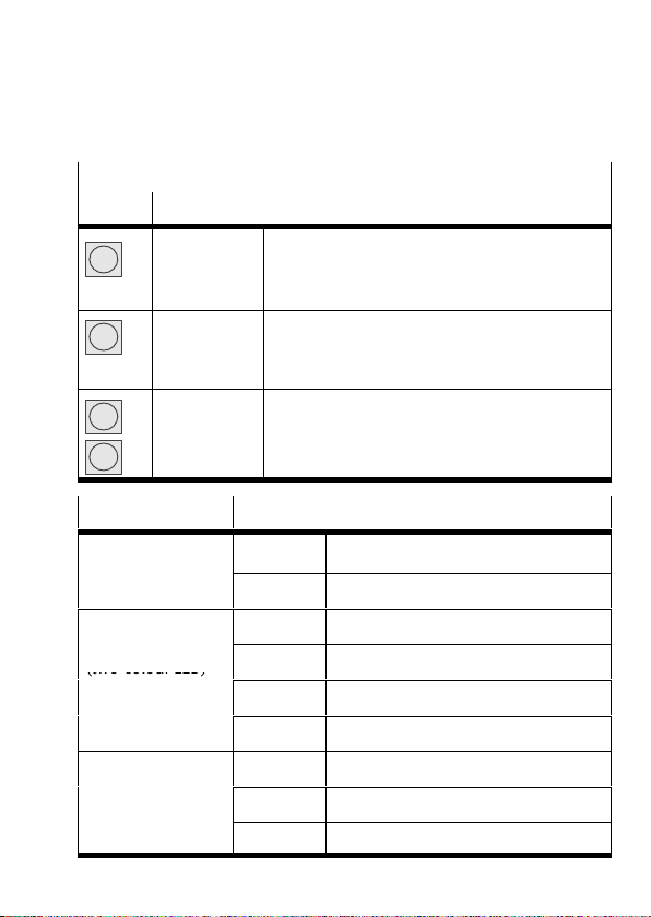
1 Control panel (only type SFC−LAC−...−H2−...)
(two colour LED)
Button Function
Menu
Enter
v
V
2 LED Status
Power
Operating voltage
I/F
Positioning status
(two−colour LED)
Fault
Fault display
Festo P.BE−K−SFC−LAC−IO 0604NH English 19
MENU
ESC
EMERG.STOP
OK
SAVE
START/STOP
{ }
EDIT
green Operating voltage applied
off No operating voltage
green Ready to operate, is enabled
green/red Ready to operate, is not enabled
off Positioning mode or fault/warning
red Controller end stage off
red Fault
flashes Warning
off No internal fault registered
Status display > Main menu
Reject entry or return to menu level
Abort current positioning procedure
Confirms the selection or entry
Saves parameter settings permanently
Starts/stops the Demo Mode
Previous/next menu command or
position manually (teach)
Increases/reduces parameter value
Page 20
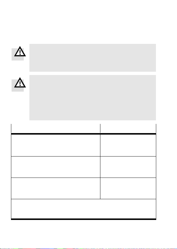
3 Notes on fitting and installation
Warning
Before carrying out fitting, installation and mainten
ance work, always switch off the power supply for the
electronic components.
Warning
If an axis is fitted in a sloping or vertical position, the
work load may slide down.
S Check whether external safety measures are necess
ary (e.g. toothed latches or moveable bolts).
You can then avoid the work load sliding down if there
is a sudden power failure.
*)
Power supply
Value
Load supply
Rated current (max. continuous current)
Peak current
Logic supply
Rated current / peak current
Internal fuse
I/O supply
Idle current / peak current
(per output max. 0.5 A)
*)
The tolerances for the voltage supplies must also be observed
directly at the connections of the SFC−LAC.
**)
Connect masses for equal basis potential !
**)
**)
48 V DC +5% / −10%
10 A
20 A
24 V DC ±10%
0.4 A / 0.8 A
2.5A very quick−acting
24 V DC ±10%
0.05 A / 2.1 A
Festo P.BE−K−SFC−LAC−IO 0604NH English20
Page 21
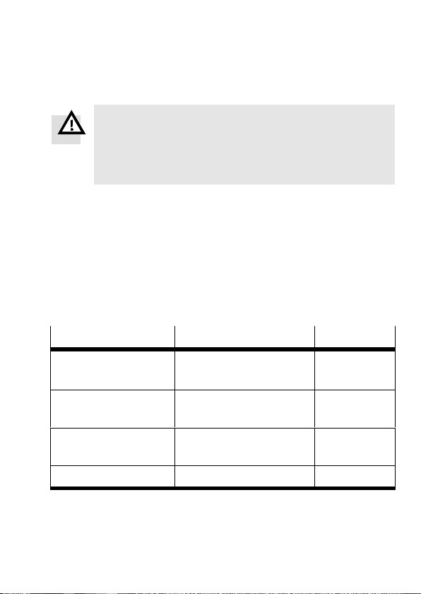
Warning
Use only power units which guarantee reliable electrical
isolation of the operating voltage as per IEC/DIN
EN60204−1. Observe also the general requirements for
PELV power circuits as per IEC/DIN EN 60204−1.
S Use a closed−loop power unit.
S To avoid electrostatic discharges and comply with
protection class IP54: Seal unused connections with
the protective caps
supplied.
S Avoiding looping to earth: Use only one of the earth
connections (e.g. 6).
S Use only these cables (note max. length):
Cable
Power supply cable
(VDC)
Motor cable (HME) KMTR−LAC−S50HC−S50HC−... 2,5 / 5 / 10
Control cable (PLC) KES−MC−1−SUB−15−... 2,5 / 5 / 10
Programming cable (PC) KDI−MC−M8−SUB−9−... 2,5
Festo P.BE−K−SFC−LAC−IO 0604NH English 21
Accessories type ... Length [m]
KPWR−MC−1−SUB−15HC−... 2,5 / 5 / 10
(max. 10 m)
(max. 10 m)
(max. 30 m)
Page 22

4 Notes on commissioning and operation
Warning
Electric axes can move suddenly with high force and at
high speed. Collisions can lead to serious injury to
human beings and damage to components.
S Make sure that:
nobody can gain access to the operating range of the
axes or other connected actuators, and that no other
objects lie in the positioning range
is connected to a power supply.
Warning
Danger of injury.
Faults in parametrization can cause injury to people and
damage to property. In the following cases reference
travel is absolutely essential in order that the reference
points and the working range can be set correctly:
during initial commissioning,
when the referencing method is changed,
If the axis zero point is modified,
each time the logic voltage supply is switched on.
S Carry out commissioning with the Festo Configuration
Tool configuration software (see FCT help system), or
optionally with the control panel (only type
SFC−LAC−...−H2).
while the system
Festo P.BE−K−SFC−LAC−IO 0604NH English22
Page 23

Overview of first commissioning with the control panel
Before switching on: Make sure that there is no ENABLE
1.
signal at the controller interface.
2. Switch on the SFC−LAC; select drive type (e.g.HME−16−200).
3. Set parameters for reference travel: methods and speeds.
4. Set controller enable for control panel: [H MI = on].
For a few seconds a search is made for the commuting
point (the HME vibrates).
5. Carry out a reference run.
6. Teach the axis parameters: Axis zero point AZ and software
end positions (if the AZ is modified: carry out new reference
travel).
7. Enter/teach position sets.
Carry out a test run Check positioning behaviour, reference
8.
points and work range.
9. If necessary, optimize the position sets, reference points
and work range.
10. Check that the controller interface functions correctly.
11. In order to complete commissioning read the instructions
on operation (see the manual for the SFC−LAC−...).
Festo P.BE−K−SFC−LAC−IO 0604NH English 23
Page 24
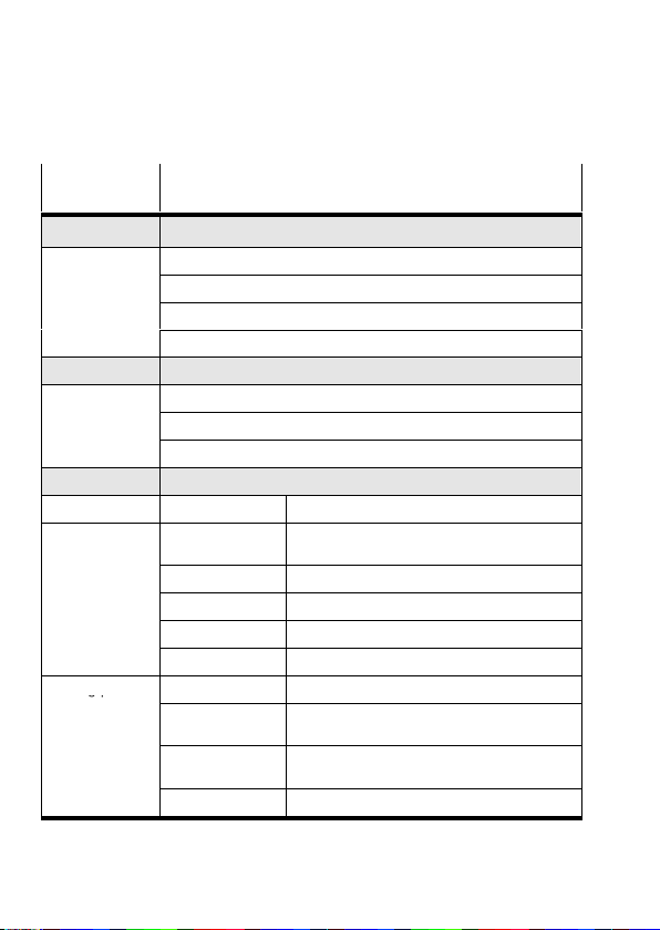
5 Menu structure (control panel)
gp
Menu
Description
command
Diagnostic Display system data + current settings
Pos. set table Display position set table
Axis param Display axis parameters and data
System param Display system parameters and data
SW information Display operating system version (firmware)
Positioning
Homing Start reference travel
Move posit set Start positioning travel Position set"
Demo posit tab Start positioning travel Pos. set table"
Settings
Axis type HME−... Linear module type HME−...
Axis parameter Zero point
Homing paramet. Homing method Select referencing method
1) 2)
Reference travel and positioning runs for testing the position sets
1)
4)
4)
1) 2)
Select the drive, parametrizing, programming the position sets
3) 4)
Offset of the axis zero point AZ to the
reference point
SW−limit−neg
SW−limit−pos
Tool load Tool mass (e.g. gripper)
SAVE... Save parameters in EEPROM
Velocity v_rp Positioning speed for searching for the
Velocity v_zp Positioning speed for moving to the axis zero
SAVE... Save parameters in EEPROM
3) 4)
Software end position, negative; related to AZ
3) 4)
Software end position, positive; related to AZ
reference point
point
Festo P.BE−K−SFC−LAC−IO 0604NH English24
Page 25
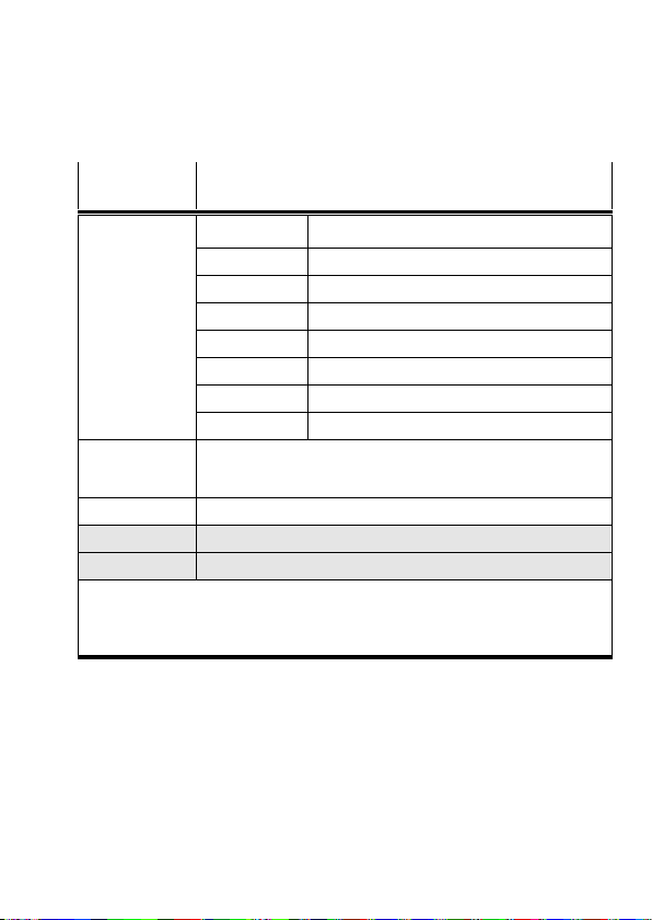
Menu
Description
command
Position set Position nr Number of the position set (1...31)
Pos set mode Mode: absolute or relative positioning
3) 4)
Position
Velocity Positioning speed
Acceleration Acceleration and deceleration
Jerk Back
Work load Work load
SAVE... Save parameters in EEPROM
Jog Mode Move drive by means of arrow buttons (also possible without
previous reference travel; software end positions are without
function).
Password edit Setting up a password for the control panel
HMI control
1)
Setting the device control via the control panel
LCD adjustment Rotate the display in steps of 180°
1)
Password protection possible
2)
The controller interface must be deactivated, see [HMI control]:HMI=on
3)
Teach mode
4)
Only after successful reference travel
Target position
Festo P.BE−K−SFC−LAC−IO 0604NH English 25
Page 26

Festo P.BE−K−SFC−LAC−IO 0604NH English26
Page 27
1 Instrucciones para el usuarioEspañol
Por favor, observar
Este breve resumen es parte de la documentación com
pleta con la denominación P.BE−SFC−LAC−UDOK. Sirve
como información preliminar y no reemplaza la docu
mentación completa, que está contenida en un archivo
PDF en el CD ROM suministrado con toda la documenta
ción (ver tabla).
S Es esencial que observe la información y
instrucciones de seguridad en el manual completo
para el controlador del motor.
S Consulte con el servicio local de Festo o escriba a la
siguiente dirección de correo electrónico si tienen
dificultades técnicas:
[email protected]
las
Contenido del CD ROM Idioma Nombre del
Manual para controlador de motor
tipoSFC−LAC−...−IO
Instalación y puesta a punto
Interface al control (I/O)
etc.
1)
= <número de artículo> + <código del idioma>.
También disponible en versión impresa con este número de artículo.
Festo P.BE−K−SFC−LAC−IO 0604NH Español 27
Alemán
Inglés
Español
Francés
Italiano
Sueco
archivo
540547
540548
540549
540550
540551
540552
1)
d1
g1
e1
f1
i1
s1
Page 28

Puede hallarse más información en:
en el sistema de ayuda del Festo Configuration
Tool (FCT):
FCT help: descripción de las funciones del FCT
SFC−LAC help: puesta a punto del SFC−LAC
en las instrucciones de funcionamiento suministradas
con el correspondiente componente, p.ej. para HME−...
Uso al que se destina
El controlador de motor SFC−LAC sirve como controlador
posición para el módulo ioneal tipo HME.
de
En el SFC−LAC−...−IO, el PLC/IPC de nivel superior se
conecta a través de entradas/salidas digitales.
Puesta punto y parametrización de los registros de
posición:
con el paquete de software FCT con el PlugIn SFC−LAC
a través de un interface RS232, o bien
con el tipo SFC−LAC−...−H2 opcionalmente
con el panel
de control (display y cuatro pulsadores).
Festo P.BE−K−SFC−LAC−IO 0604NH Español28
Page 29
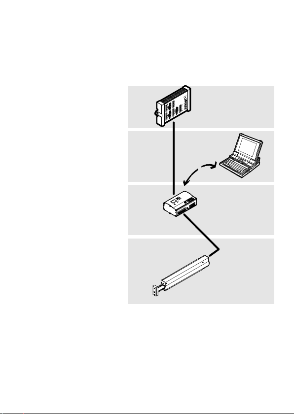
1 Control de nivel
superior, p.ej. Festo
tipo FEC−...
2 Nivel de software:
Festo Configuration
Tool
3 Nivel de controla
dor: SFC−LAC
4 Nivel de acciona
miento del motor:
HME−...
1
2
3
4
Festo P.BE−K−SFC−LAC−IO 0604NH Español 29
Page 30
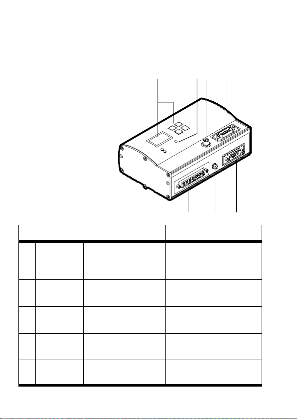
2 Elementos de indicación y conexión
1 Panel de control
(sólo tipo
SFC−LAC−...−H2−...)
12 4
2 LEDs
3 Parametrización
4 Controlador
(PLC/IPC)
5 Alimentación
6 Tierra (FE)
7 HME−...
Conexión en el SFC−LAC−...−IO Descripción
Parametriza
3
ción
Controlador Sub−D 15 pines
4
Alimenta
5
ción
Puesta a
6
tierra
HME−... Sub−D, 24W7
7
M8, 4−pines
Zócalo
Clavija
Clavija Sub−D, 7W2
Clavija
Espárrago M4 Tierra funcional (FE)
Zócalo
Interface RS232 para
parametrización, puesta a
punto y diagnosis
Interface para conectar a
un controlador PLC
Conexión de alimentación
Interface al HME−...
3
567
Festo P.BE−K−SFC−LAC−IO 0604NH Español30
Page 31
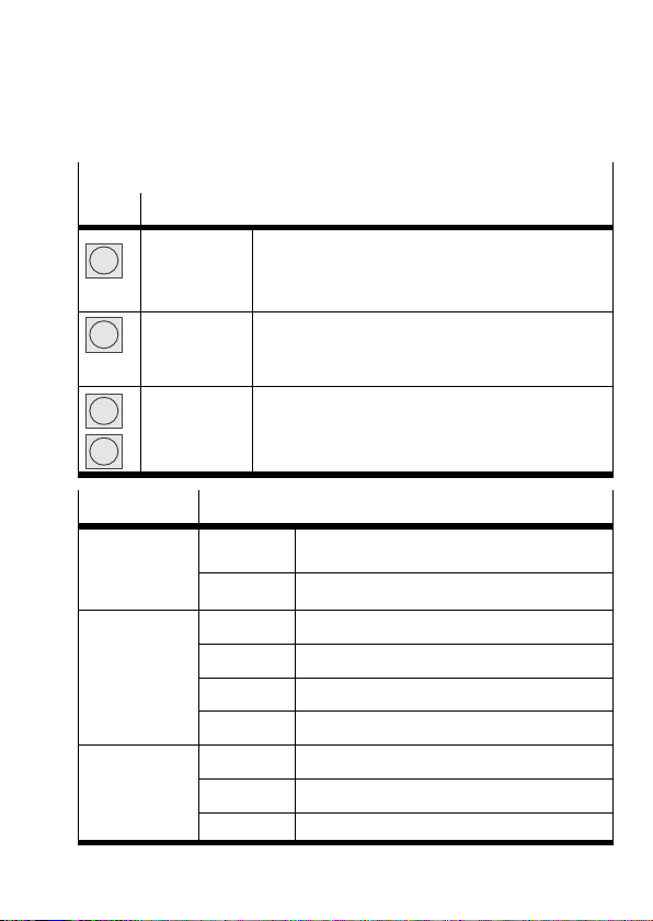
1 Panel de control (sólo tipo SFC−LAC−...−H2−...)
T
posiciona
(LED bicolor)
fallo
Botón Función
Festo P.BE−K−SFC−LAC−IO 0604NH Español 31
MENU
Menu
ESC
EMERG.STOP
OK
Enter
SAVE
START/STOP
{ }
v
EDIT
V
2 LED Estado
Power
verde Tensión de funcionamiento aplicada
ensión de
funcionam.
I/F
Estado del
posiciona
miento
apagado No hay tensión de funcionamiento
verde Listo para funcionar, está habilitado
verde/rojo Listo para funcionar, no está habilitado
apagado Modo de posicionado o error/advertencia
rojo Etapa final del controlador desconectada
Fallo
Indicador de
fallo
rojo Fallo
parpadea Atención
apagado No se ha registrado fallo interno
Indicación de estado > Menú principal
Descartar entrada o regresar al nivel de menú
Interrumpir el procedimiento en curso
Confirma la selección o entrada actual
Guarda permanentem. los ajustes de parámet.
Inicia/detiene el modo Demo
Anterior/siguiente orden de menú o
posiciona manualmente (teach)
Aumenta/reduce el valor del parámetro
Page 32
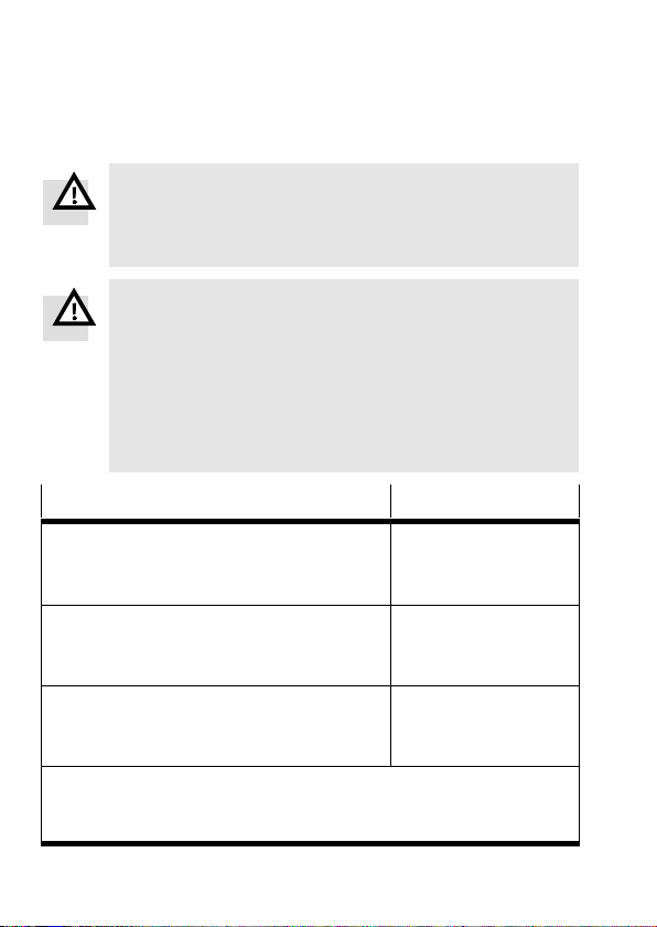
3 Notas sobre el montaje e instalación
Atención
Antes de realizar trabajos de instalación o
mantenimiento, desconectar siempre la alimentación
de los componentes electrónicos.
Atención
Si un eje está montado en posición vertical o inclinada,
la carga de trabajo puede deslizarse.
S Verifique si es necesario tomar medidas auxiliares
externas adicionales (p.ej. trinquetes de retención o
pasadores móviles).
Con ello se evita que caiga la masa si hay un fallo de
tensión inesperado.
*)
Alimentación
Valor
Alimentación de la carga
Corriente nominal (intensidad contin. máx.)
Corriente de pico
Suministro de la lógica
Corriente nominal / corriente de pico
Fusible interno
Alimentación I/O
Corriente en vacío / corriente de pico
(por salida máx. 0,5 A)
*)
Hay que observar las tolerancias para la tensión de alimentación
directamente en las conexiones del SFC−LAC.
**)
Conecte las masas para ecualizar el potencial de base.
**)
**)
Festo P.BE−K−SFC−LAC−IO 0604NH Español32
48 V DC +5/−10%
10 A
20 A
24 V DC ±10%
0,4 A / 0,8 A
2,5A de acción rápida
24 V DC ±10%
0,05 A / 2,1 A
Page 33
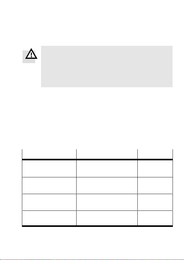
Atención
Utilice solamente fuentes de alimentación que garanti
cen un aislamiento fiable de la tensión de funciona
miento según IEC/DIN EN 60204−1. Observe también
los requerimientos generales para los circuitos de
potencia PELV según IEC/DIN EN 60204−1.
S Utilizar fuentes de alimentación reguladas.
S Evitar descargas electrostáticas y cumplir con la clase
de protección IP54: Cierre
las conexiones no utilizadas
con la caperuza de protección suministrada.
S Evite los bucles a tierra: Utilice sólo una de las
conexiones a tierra (p.ej. 6).
S Utilice sólo estos cables (observe la máx. longitud):
Cable
Cable de alimentación
(V DC)
Cable del motor
(HME)
Cable de control
(PLC)
Cable de programación
(PC)
Festo P.BE−K−SFC−LAC−IO 0604NH Español 33
Tipo de accesorios ... Longitud [m]
KPWR−MC−1−SUB−15HC−... 2,5 / 5 / 10
(máx. 10 m)
KMTR−LAC−S50HC−S50HC−... 2,5 / 5 / 10
(máx. 10 m)
KES−MC−1−SUB−15−... 2,5 / 5 / 10
(máx. 30 m)
KDI−MC−M8−SUB−9−... 2,5
Page 34

4 Notas sobre la puesta a punto y
funcionamiento
Atención
Los accionamientos eléctricos pueden moverse
inesperadamente con fuerzas elevadas y altas
velocidades. Las colisiones pueden causar lesiones
graves a las personas y daños materiales.
S Asegúrese de que:
nadie pueda acceder al margen operativo de los
actuadores conectados y de que no haya objetos en
el margen de posicionado mientras el sistema se
halle conectado
Atención
Riesgo de lesiones.
Los fallos en la parametrización pueden causar lesiones
a las personas o daños a los equipos. En los siguientes
casos es absolutamente esencial un recorrido de
referencia para establecer correctamente los puntos de
referencia y el margen de trabajo:
durante la puesta a punto inicial,
cuando se cambie el método de
si se modifica el punto cero del eje,
cada vez que se aplique la tensión de alimentación.
a la alimentación de corriente.
referencia,
S Realice la puesta a punto con el software Festo
Configuration Tool (véase la ayuda de FCT) u opcional
mente con el panel de control (sólo con el tipo
SFC−LAC−...−H2).
Festo P.BE−K−SFC−LAC−IO 0604NH Español34
Page 35

Resumen de la primera puesta a punto con el panel de
control
Antes de poner en marcha: Asegúrese de que no hay una
1.
señal de ENABLE en el interface del controlador.
2. Encienda el SFC−LAC; seleccione el tipo de accionamiento
(p.ej. HME−16−200).
3. Establezca los parámetros para el recorrido de referencia:
métodos y velocidades.
4. Habilite el controlador (ENABLE) para el panel de control:
[HMI = on]. Durante unos segundos se hace una búsqueda
del punto de conmutación (el HME vibra).
5. Realice un recorrido de referencia.
6. Programe (Teach) los parámetros del eje: Punto cero del eje
AZ y posiciones finales por software (si el AZ es modificado:
realice un nuevo recorrido de referencia).
7. Introduzca / programe (Teach) registros de posición.
Realice una prueba. Verifique el comportamiento del
8.
posicionado, puntos de referencia y margen de trabajo.
9. Si es necesario, optimice los registros de posiciones,
puntos de referencia y margen de trabajo.
10. Verifique que el interface del controlador funciona
correctamente.
11. Para completar la puesta a punto, léase las instrucciones
sobre el funcionamiento (ver el manual del SFC−LAC−...).
Festo P.BE−K−SFC−LAC−IO 0604NH Español 35
Page 36
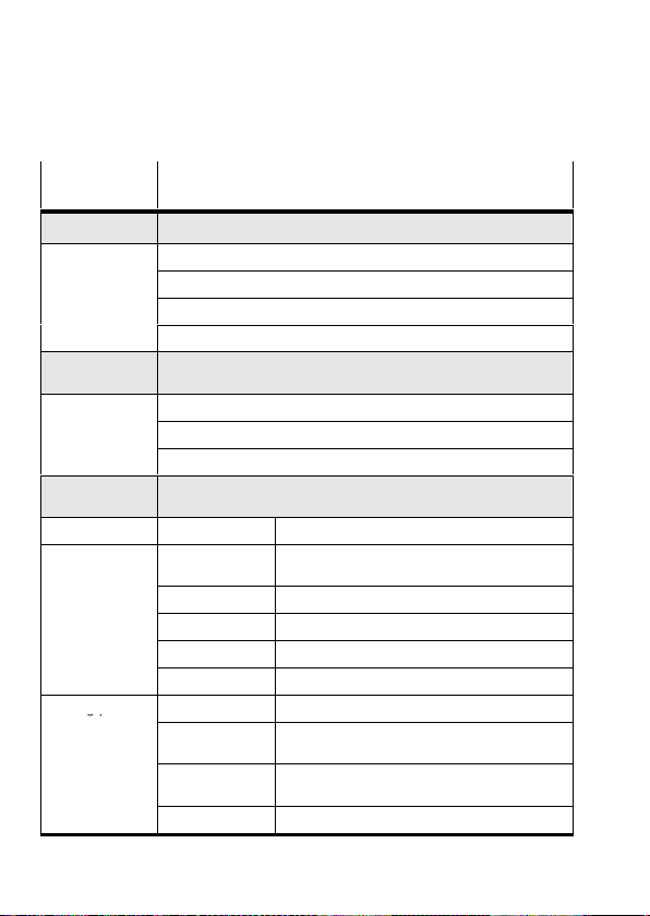
5 Estructura del menú (panel de control)
gp
Orden del
Descripción
menú
Diagnostic Visualización de datos del sistema + ajustes actuales
Pos. set table Muestra la tabla de registros de posiciones
Axis param Mostrar los parámetros y datos de los ejes
System param Muestra los parámetros y datos del sistema
SW information Muestra la versión del sistema operativo (firmware)
Positioning
Homing Inicio del recorrido de referencia
Move posit set Inicia el recorrido de posicionado Position set"
Demo posit tab Inicia el recorrido de posicionado Pos. set table"
Settings
Axis type HME−... Módulo lineal tipo HME−...
Axis parameter Zero point
Homing paramet. Homing Method Selecciona el método de referencia
1) 2)
Recorrido de referencia y recorrido de posicionado para verificar
los registros de posiciones
1) 2)
Seleccionar el accionamiento, parametrización programación y
registros de posicionado
3) 4)
Desplazamiento del punto cero del eje AZ al
punto de referencia
SW−limit−neg
SW−limit−pos
Tool load Masa de la herramienta (p.el. pinza)
SAVE... Guardar parámetros en EEPROM
Velocity v_rp Velocidad de posicionado para alcanzar el
Velocity v_zp Velocidad de posicionado para moverse al
SAVE... Guardar parámetros en EEPROM
3) 4)
Posi. final por software, negativa; relativa a AZ
3) 4)
Posi. final por software, positiva; relativa a AZ
punto de referencia
punto cero del eje
1)
4)
4)
Festo P.BE−K−SFC−LAC−IO 0604NH Español36
Page 37
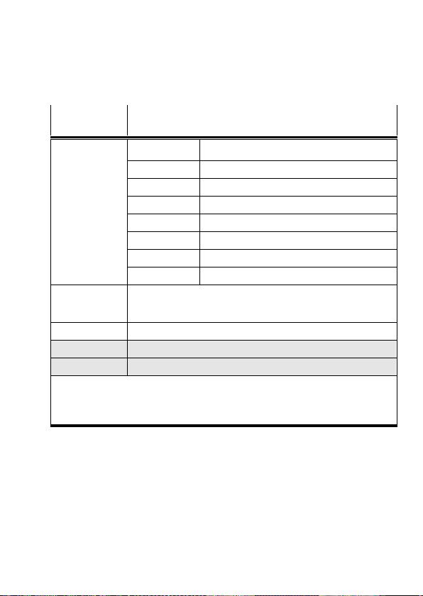
Orden del
Descripción
menú
Position set Position nr Número del registro de posiciones (1...31)
Pos set mode Modo: posicionado absoluto o relativo
3) 4)
Position
Velocity Velocidad de posicionado
Acceleration Aceleración y deceleración
Jerk Retroceso
Work load Carga de trabajo
SAVE... Guardar parámetros en EEPROM
Jog Mode Mover el accionamiento por medio de los botones de flecha
(también posible sin recorrido de referencia previo; las posiciones
finales por software no tienen ninguna finción).
Password edit Establecer una clave de acceso para el panel de control
HMI control
1)
Ajustar el control del dispositivo a través del panel de control
LCD adjustment Girar el display en pasos de 180°
1)
Es posible una protección por password.
2)
El interface del control debe estar desactivado , ver [HMI control]: HMI = on
3)
Modo Teach
4)
Sólo tras un recorrido de referencia correcto.
Posición de destino
Festo P.BE−K−SFC−LAC−IO 0604NH Español 37
Page 38

Festo P.BE−K−SFC−LAC−IO 0604NH Español38
Page 39
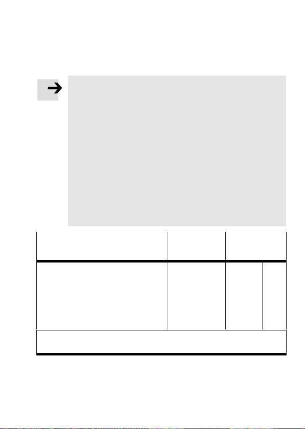
1 Remarques pour l’utilisateurFrançais
Note
Cette notice simplifiée fait partie de la documentation
du type P.BE−SFC−LAC−UDOK. Elle sert uniquement à
une première information et ne remplace pas la docu
mentation complète, qui est disponible sous forme de
fichier PDF sur le CD−ROM joint à la documentation
(voirtableau).
S Respecter impérativement les informations et
consignes de sécurité figurant dans la
documentation
S En cas de problème technique, merci de vous adres
ser au service après−vente Festo le plus proche ou
d’envoyer un courrier électronique à l’adresse sui
vante : [email protected]
complète du contrôleur de moteur.
Contenu du CD−ROM
Description du contrôleur de
moteur de typeSFC−LAC−...−IO
Installation et mise en service
Interface de commande (E/S)
etc.
1)
= <Référence> + <Code de langue>.
Egalement disponible en version papier sous cette référence.
Festo P.BE−K−SFC−LAC−IO 0604NH Français 39
Langue Nom du
fichier
Allemand
Anglais
Espagnol
Français
Italien
Suédois
540547
540548
540549
540550
540551
540552
1)
d1
g1
e1
f1
i1
s1
Page 40

D’autres informations sont disponibles :
dans le système d’aide du logiciel de configuration
Festo Configuration Tool (FCT) :
FCT help : description des fonctions FCT
SFC−LAC help : mise en service du SFC−LAC
dans la notice d’utilisation jointe aux différents
composants p.ex. HME−...
Utilisation conforme à l’usage prévu
Le contrôleur de moteur SFC−LAC est une commande de
positionnement et un asservissement de position pour le
module linéaire HME.
L’API/IPC de niveau supérieur est raccordée, pour le
SFC−LAC−...−IO, via des entrées/sorties TOR.
La mise en service et le paramétrage de l’enregistrement
de référence sont réalisés :
à l’aide du progiciel FCT et du PlugIn SFC−LAC via
l’interface RS232 ou
pour le type SFC−LAC−...−H2−...
en option avec le
pupitre de commande (écran et 4 touches de
fonction).
Festo P.BE−K−SFC−LAC−IO 0604NH Français40
Page 41
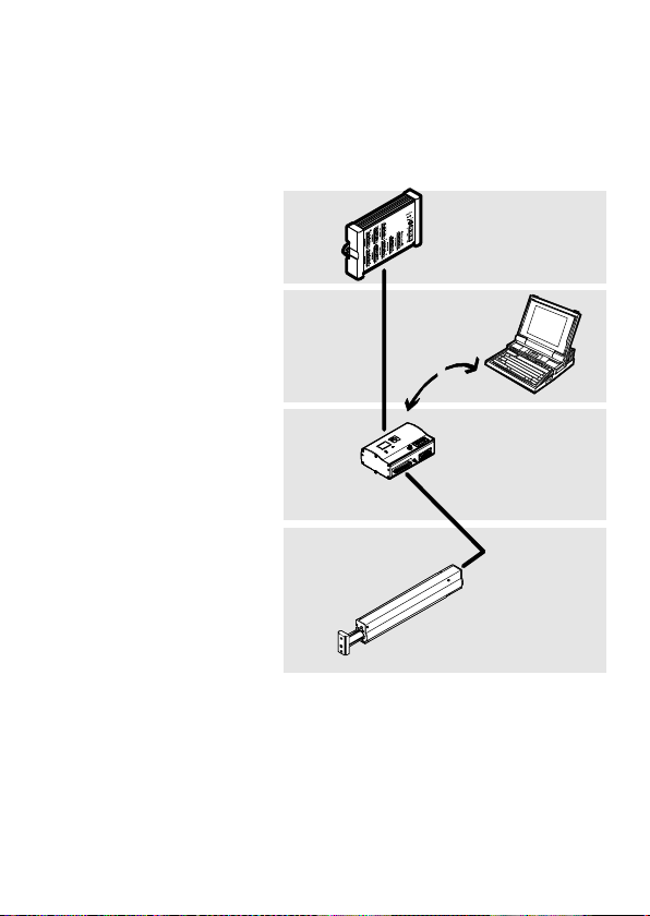
1 Automate de niveau
supérieur p.ex.
Festo de type FEC...
2 Niveau logiciel :
Festo Configuration
Tool
3 Niveau contrôleur :
SFC−LAC
4 Niveau entraîne
ment moteur :
HME−...
1
2
3
4
Festo P.BE−K−SFC−LAC−IO 0604NH Français 41
Page 42
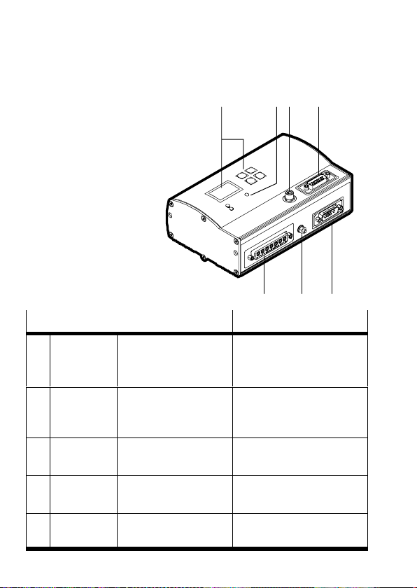
2 Eléments de signalisation et de raccordement
1 Pupitre de
commande
(uniquement type
SFC−LAC−...−H2−...)
12 4
2 LED
3 Paramétrage
4 Commande (API/IPC)
5 Alimentation
électrique
6 Mise à la terre (FE)
7 HME−...
Raccordement au SFC−LAC−...−I0 Description
Paramé
3
trage
Commande Sub−D, à 15 pôles
4
Alimentation
5
électrique
Mise à la
6
terre
M8, à 4 pôles
Connecteur femelle
Connecteur
Sub−D, 7W2
Connecteur mâle
Goujon M4 Terre du système (FE)
Interface RS232 pour le
paramétrage, la mise en
service, et le diagnostic
Interface pour le raccorde
ment à la commande API
souhaitée
Connexion de l’alimenta
tion électrique
3
567
HME−... Sub−D, 24W7
7
Connecteur femelle
Interface du HME−...
Festo P.BE−K−SFC−LAC−IO 0604NH Français42
Page 43
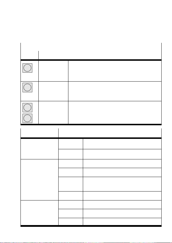
1 Pupitre de commande (uniquement type SFC−LAC−...−H2−...)
T
positionnement
erreurs
Touche Fonction
Menu
Enter
v
V
2 LED Etat
Power
ension de
service
I/F
Etat de
positionnement
(LED bicolore)
Error
Affichage des
erreurs
Festo P.BE−K−SFC−LAC−IO 0604NH Français 43
MENU
ESC
EMERG.STOP
OK
SAVE
START/STOP
{ }
EDIT
vert Tension de service présente
éteinte Absence de tension de service
vert Opérationnel, validation présente
vert/rouge Opérationnel, validation manquante
éteinte Mode de positionnement ou erreur/
rouge Etage de sortie du régulateur éteint
rouge Erreur
clignote Avertissement
éteinte Aucune erreur interne signalée
Affichage d’état > Menu principal
Supprimer la saisie ou retour au menu
Interrompre le positionnement en cours
Confirme la sélection ou la saisie
Enregistre définitivement les paramétrages
Démarre/arrête le mode Démo
Commande de menu précédente/suivante ou
procédure manuelle (Teachen Apprentissage)
Augmente/réduit la valeur du paramètre
avertissement
Page 44

3 Consignes de montage et d’installation
Avertissement
Avant toute intervention de montage, d’installation ou
de maintenance, couper l’alimentation de l’électronique.
Avertissement
Lors d’un montage vertical ou incliné de l’axe, risque de
chute de la charge !
S Vérifier si des mesures de sécurité supplémentaires
externes sont nécessaires (p.ex. cliquets de retenue
ou axes mobiles).
Cela permet d’éviter, en cas de coupure de courant, une
chute soudaine de la masse utile.
Alimentation électrique
Alimentation principale
Courant nominal (courant perm. max.)
Courant de pointe
Alimentation logique
Courant nominal / courant de pointe
Fusible interne
Alimentation E/S
Courant à vide / Courant de pointe
(par sortie max. 0,5 A)
*)
Les tolérances pour les alimentations électriques doivent également
être respectées directement au niveau des connecteurs du SFC−LAC.
**)
Raccorder les masses pour un même potentiel de référence !
*)
**)
**)
Valeur
48 Vcc +5/−10%
10 A
20 A
24 Vcc ±10%
0,4 A / 0,8 A
2,5A ultrarapide
24 Vcc ±10%
0,05 A / 2,1 A
Festo P.BE−K−SFC−LAC−IO 0604NH Français44
Page 45
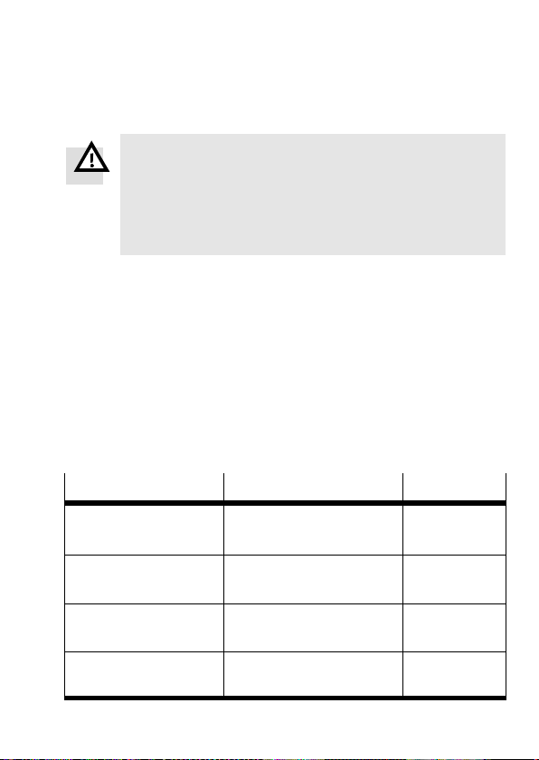
Avertissement
Utiliser exclusivement des alimentations garantissant
une isolation électrique de l’alimentation conforme à la
norme CEI/DIN EN 60204−1. Tenir compte également
des exigences générales qui s’appliquent aux circuits
électriques TBT selon CEI/DIN EN 60204−1.
S Utiliser une alimentation régulée.
S Pour éviter les décharges électrostatiques et pour
respecter l’indice de protection IP54 : obturer les
connecteurs
inutilisés avec les capuchons de
protection fournis.
S Pour éviter les circuits de masse : n’utiliser qu’une
seule des bornes de terre (p.ex. 6).
S Utiliser exclusivement les câbles suivants (respecter la
longueur max.) :
Câbles
Câble d’alimentation
(Vcc)
Câble moteur (HME) KMTR−LAC−S50HC−S50HC−... 2,5 / 5 / 10
Câble de commande
(API)
Câble de programma
tion (PC)
Festo P.BE−K−SFC−LAC−IO 0604NH Français 45
Accessoires de type ... Longueur [m]
KPWR−MC−1−SUB−15HC−... 2,5 / 5 / 10
(max. 10 m)
(max. 10 m)
KES−MC−1−SUB−15−... 2,5 / 5 / 10
(max. 30 m)
KDI−MC−M8−SUB−9−... 2,5
Page 46

4 Consignes de mise en service et d’utilisation
Avertissement
Les axes électriques peuvent se déplacer à grande
vitesse et avec une force importante. Des collisions
peuvent causer de graves blessures ou détruire des
composants.
S Vérifier que personne ne peut entrer dans la zone
d’intervention des axes et d’autres actionneurs
fermés et qu’aucun objet ne se trouve dans la zone
de déplacement, tant
une source d’énergie.
Avertissement
Risque de blessure !
Les erreurs de paramétrage peuvent provoquer des
blessures corporelles et des dommages matériels. Pour
le réglage correct des points de base et de la zone de
travail, un déplacement de référence doit
impérativement être effectué dans les cas suivants :
lors de la première mise en service,
après modification de
référence,
en cas de modification du point zéro de l’axe,
après chaque activation de l’alimentation logique !
que le système est raccordé à
la méthode de prise de
S Effectuer la mise en service à l’aide du Festo Configu
ration Tool (voir le système d’aide FCT) ou du pupitre
de commande (uniquement type SFC−LAC−...−H2).
Festo P.BE−K−SFC−LAC−IO 0604NH Français46
Page 47

Récapitulatif de la première mise en service avec le
pupitre de commande
Avant la mise en marche : S’assurer qu’aucune commande
1.
ENABLE n’est présente sur l’interface de commande (API).
2. Mettre en marche le SFC−LAC ; sélectionner le type
d’entraînement (p.ex. HME−16−200).
3. Définir les paramètres du déplacement de référence :
méthode et vitesses.
4. Définir l’activation de la commande pour le pupitre de com
mande : [HMI = on]. La recherche du point de commutation
s’effectue à présent pendant quelques secondes (le HME
vibre).
5. Effectuer un déplacement de référence.
6. Apprentissage des paramètres de l’axe : Point zéro de l’axe
AZ et fins de course logicielles (en cas de modification de
l’AZ : nouveau déplacement de référence).
7. Entrée / Apprentissage des enregistrements de
déplacement.
8. Effectuer un déplacement d’essai. Contrôler la qualité du
déplacement, les points de base et la zone de travail.
9. Si nécessaire, optimiser les enregistrements de déplace
ment, les points de base et la zone de travail.
10. Tester le fonctionnement de l’interface de commande.
11. Pour terminer la mise en service, respecter les consignes
d’utilisation (voir notice du SFC−LAC−...).
Festo P.BE−K−SFC−LAC−IO 0604NH Français 47
Page 48
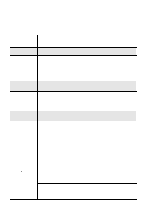
5 Structure des menus (pupitre de commande)
gp
Commande
Description
de menu
Diagnostic Affichage des données du système + réglages actuels
Pos. set table Affichage du tableau d’enregistrements de déplacement
Axis param Affichage des paramètres et des données d’axe
System param Affichage des paramètres et des données du système
SW information Affichage de la version du système d’exploitation (microprogr.)
Positioning
Homing Lancement du déplacement de référence
Move posit set Lancement du déplacement de positionnement Position set"
Demo posit tab Lancement du déplacement de positionnement Pos. set table"
Settings
Axis type HME−... Module linéaire HME−...
Axis parameter Zero point
Homing paramet. Homing method Sélection de la méthode de prise de référence
1) 2)
Déplacement de référence et déplacements de positionnement
pour tester les enregistrements de déplacement
1) 2)
Sélection de l’entraînement, paramétrage, programmation des
enregistrements de déplacement
3) 4)
Décalage du point zéro de l’axe AZ par rapport
au point de référence
SW−limit−neg
SW−limit−pos
Tool load Masse d’outil (p.ex. pince)
SAVE... Enregistrement des paramètres dans la
Velocity v_rp Vitesse de déplacement pour la recherche du
Velocity v_zp Vitesse de déplacement pour l’accostage du
SAVE... Enregistr. des param. dans la mémoire EEPROM
3) 4)
Fin de course logic., négative, rapportée au AZ
3) 4)
Fin de course logic., positive, rapportée au AZ
mémoire EEPROM
point de référence
point zéro de l’axe
1)
4)
4)
Festo P.BE−K−SFC−LAC−IO 0604NH Français48
Page 49
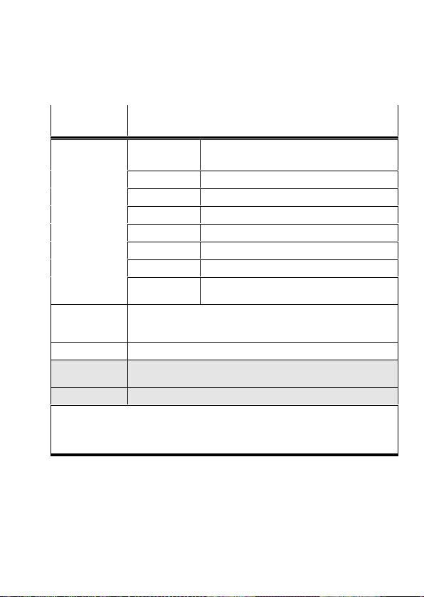
Commande
de menu
Description
Position set Position nr Numéro de l’enregistrement de déplacement
(1à 31)
Pos set mode Mode : positionnement absolu ou relatif
3) 4)
Position
Position cible
Velocity Vitesse de déplacement
Acceleration Accélération et temporisation
Jerk A−coup
Work load Charge utile
SAVE... Enregistrement des paramètres dans la
Jog Mode Déplacement de l’entraînement à l’aide des touches fléchées
(possible sans déplacement de référence antérieur; fins de course
logicielles sans fonction).
mémoire EEPROM
Password edit Définition d’un mot de passe pour le pupitre de commande
HMI control
1)
Réglage de la commande de l’appareil via le pupitre de
commande
LCD adjustment Rotation de l’affichage sur l’écran de 180°
1)
Le cas échéant, protection par mot de passe
2)
L’interface de commande doit être désactivée, voir [HMI control] : HMI = on
3)
Mode d’apprentissage
4)
Uniquement après un déplacement de référence réussi
Festo P.BE−K−SFC−LAC−IO 0604NH Français 49
Page 50

Festo P.BE−K−SFC−LAC−IO 0604NH Français50
Page 51
1 Indicazioni per l’utilizzatoreItaliano
Nota
Questa breve panoramica è parte integrante del pac
chetto di documentazione tipo P.BE−SFC−LAC−UDOK.
Serve solo come prima informazione e non sostituisce
la documentazione completa, che è registrata come file
PDF sul CD−ROM in dotazione del pacchetto (vedi ta
bella).
S Osservare assolutamente le informazioni e le norme
di sicurezza riportate nella descrizione completa del
controllore
S Se dovessero sorgere problemi tecnici, rivolgersi al
servizio assistenza locale Festo o al seguente indi
rizzo e−mail: [email protected]
a motore.
Contenuto del CD−ROM
Descrizione del controllore a
motore tipoSFC−LAC−...−IO
installazione e messa in servizio
interfaccia di controllo (I/O)
ecc.
1)
= <codice prodotto> + <identificazione della lingua> Disponibile
anche in versione su carta specificando questo codice prodotto.
Festo P.BE−K−SFC−LAC−IO 0604NH Italiano 51
Lingua Nome file
Tedesco
Inglese
Spagnolo
Francese
Italiano
Svedese
540547
540548
540549
540550
540551
540552
1)
d1
g1
e1
f1
i1
s1
Page 52

Ulteriori informazioni sono riportate:
nel sistema di aiuto del software Festo Configuration
Tool (FCT):
aiuto FCT: descrizione delle funzioni FCT
aiuto SFC−LAC: messa in servizio SFC−LAC
nelle istruzioni d’uso accluse ai rispettivi componenti,
ades. per HME−...
Impiego ammesso
Il controllore a motore SFC−LAC viene utilizzato come co
mando di posizionamento e regolatore di posizione per il
modulo lineare
HME.
PLC e IPC vengono collegati tramite ingressi/uscite digitali
nel tipo SFC−LAC−...−IO.
Messa in servizio e parametrazione dei record di posizio
namento vengono eseguite
con il pacchetto software FCT e il PlugIn SFC−LAC
tramite l’interfaccia RS232 o
per il tipo SFC−LAC−...−H2−... opzionalmente con il
pannello di comando (display e 4 tasti operativi).
Festo P.BE−K−SFC−LAC−IO 0604NH Italiano52
Page 53
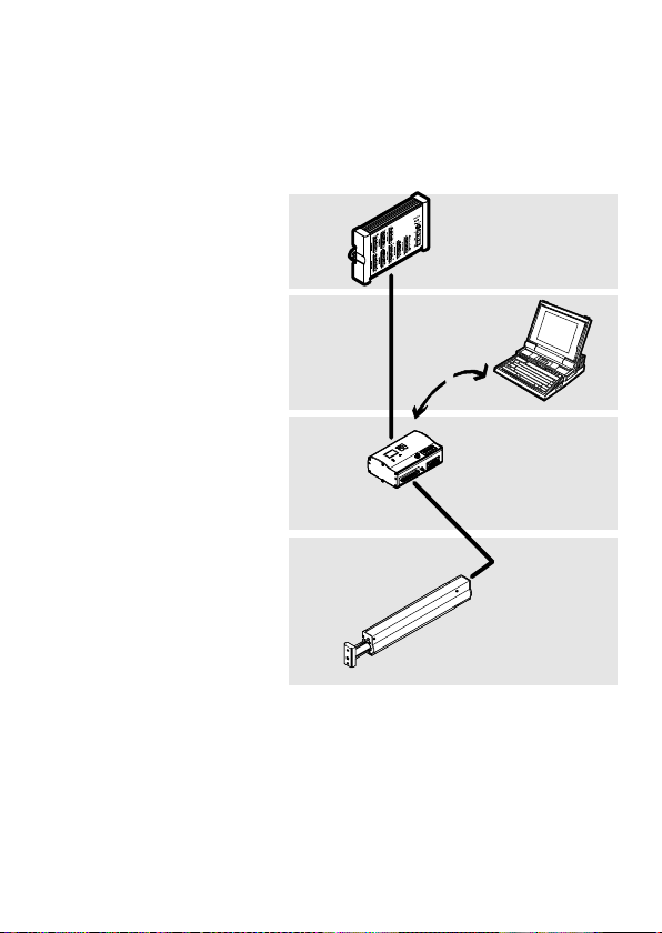
1 Comando host,
ades. Festo tipo
FEC...
2 Livello software:
Festo Configuration
Tool
3 Livello controllore:
SFC−LAC
4 Livello di
azionamento
motore: HME−...
1
2
3
4
Festo P.BE−K−SFC−LAC−IO 0604NH Italiano 53
Page 54
2 Elementi di segnalazione e di collegamento
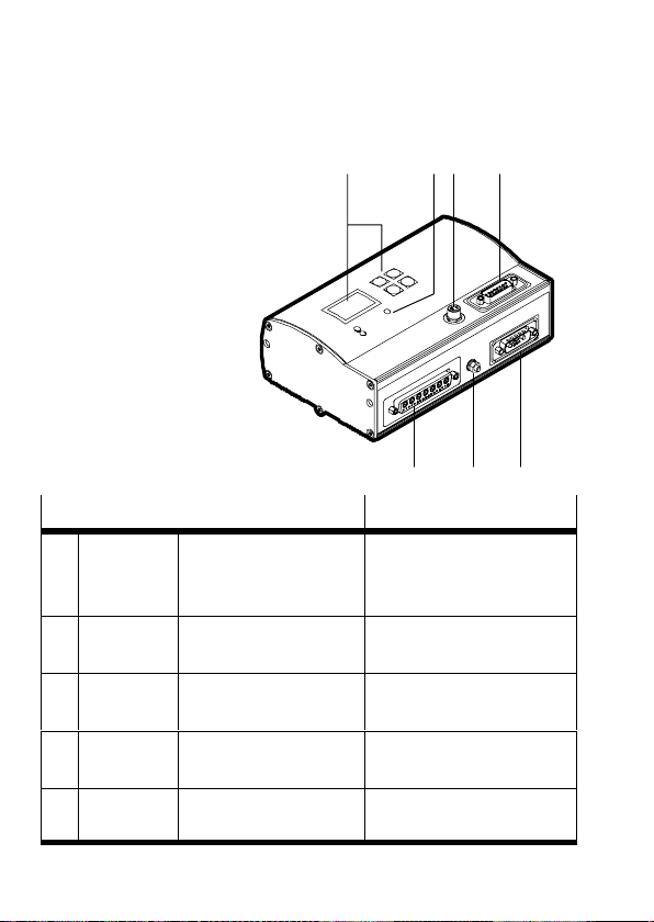
1 Pannello di
comando (solo tipo
SFC−LAC−...−H2−...)
12 4
2 LED
3 Parametrazione
4 Comando (PLC/IPC)
5 Alimentazione
elettrica
6 Messa a terra (FE)
7 HME−...
Connessione all’SFC−LAC−...−I0 Descrizione
Parametra
3
zione
Comando SUB−D a 15 poli
4
Alimentaz.
5
elettrica
Messa a
6
terra
HME−... Sub−D, 24W7
7
M8, 4 poli
Connettore femmina
Connettore maschio
Sub−D, 7W2
Connettore maschio
Perno distanziatoreM4Messa a terra (FE)
Connettore femmina
Interfaccia RS232 per
parametrare, messa in
servizio e diagnosi
Interfaccia per la connes
sione ad un comando PLC
Attacco alimentazione
elettrica
Interfaccia all’HME−...
3
567
Festo P.BE−K−SFC−LAC−IO 0604NH Italiano54
Page 55
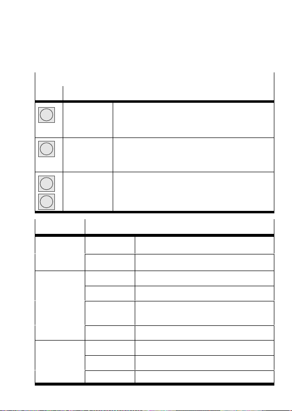
1 Pannello di comando (solo tipo SFC−LAC−...−H2−...)
T
posiziona
di errore
Tasto Funzione
Menu
Enter
v
V
MENU
ESC
EMERG.STOP
OK
SAVE
START/STOP
{ }
EDIT
Indicazione di stato > Menu principale
Eliminare impostaz. o ritornare al livello di menu
Interrompere processo di posizionam. corrente
Conferma selezione o impostazione
Memor. permanent. le impostaz. dei parametri
Avvia/arresta modalità Demo
Comando di menu precedente/successivo o
traslazione manuale (Teach)
Aumenta/riduce valore di parametro
2 LED Stato
Power
verde Tensione d’esercizio applicata
ensione
d’esercizio
I/F
Stato di
posiziona
mento (LED
a due colori)
off Tensione d’esercizio non applicata
verde Pronto, abilitazione presente
verde/rosso Pronto, abilitazione mancante
off Esercizio di posizionamento o
errore/avvertenza
rosso Modulo terminale del regolatore off
Error
Indicazione
di errore
rosso Errore
lampeggia. Avvertenza
off Non viene segnal. nessun errore interno
Festo P.BE−K−SFC−LAC−IO 0604NH Italiano 55
Page 56
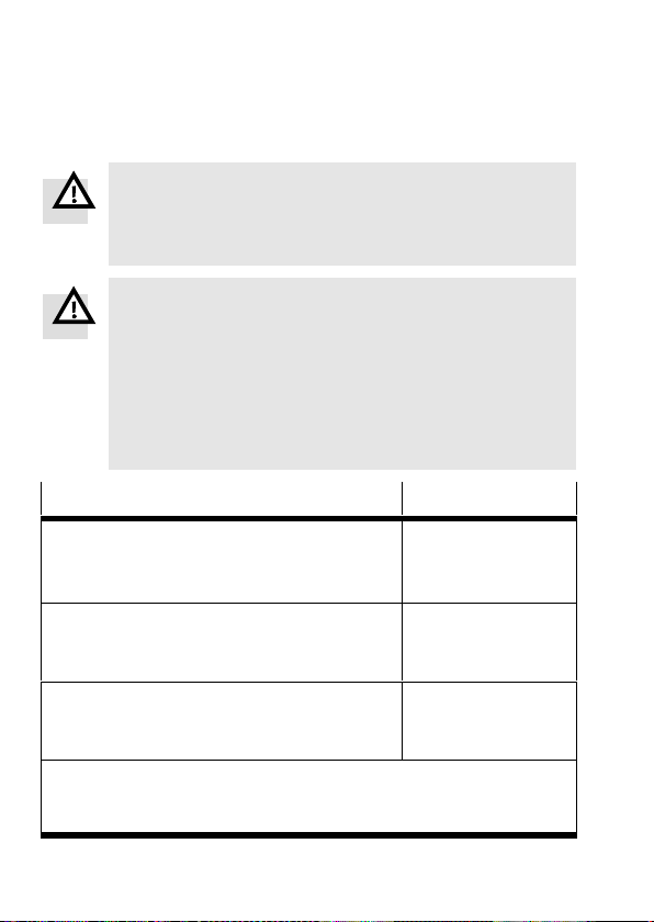
3 Istruzioni di montaggio e installazione
Avvertenza
Prima di iniziare qualsiasi intervento di montaggio,
installazione e manutenzione, disinserire
l’alimentazione elettrica del sistema elettronico.
Avvertenza
I carichi possono cadere quando l’asse viene montato
in posizione inclinata o verticale!
S Verificare l’opportunità di misure di sicurezza esterne
(ades. nottolini o perni mobili).
Solo questa configurazione è in grado di impedire l’im
provviso scivolamento in basso del carico di lavoro in
caso di interruzione dell’alimentazione elettrica.
*)
Alimentazione elettrica
Valore
Alimentazione di carico
corrente nominale (corrente continua max.)
corrente di picco
Alimentazione logica
corrente nominale / corrente di picco
fusibile interno
Alimentazione I/O
corrente a vuoto / corrente di picco
(max. 0,5 A per ogni uscita)
*)
Osservare le tolleranze per l’alimentazione elettrica anche
direttamente sulle connessioni dell’SFC−LAC.
**)
Collegare le masse per lo stesso potenziale di riferimento.
**)
**)
Festo P.BE−K−SFC−LAC−IO 0604NH Italiano56
48 VCC +5/−10%
10 A
20 A
24 VCC ±10%
0,4 A / 0,8 A
2,5A ultrarapido
24 VCC ±10%
0,05 A / 2,1 A
Page 57
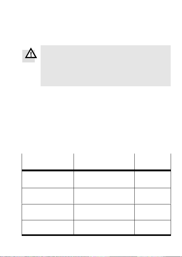
Avvertenza
Utilizzare esclusivamente alimentazioni elettriche in
grado di garantire un sezionamento elettrico sicuro
della tensione d’esercizio secondo IEC/DIN EN60204−1.
Attenersi inoltre ai requisiti generali previsti per i cir
cuiti elettrici PELV secondo IEC/DIN EN 60204−1.
S Utilizzare un alimentatore a circuito chiuso.
S Per evitare scariche elettrostatiche e osservare il grado
di protezione IP54: chiudere le
connessioni non
utilizzate con i cappucci di protezione in dotazione.
S Per evitare anelli di massa: utilizzare solo una delle
connessioni di messa a terra (ades. 6).
S Utilizzare solo questi cavi (fare attenzione alla lun
ghezza max.):
Cavi
Tipo di accessori ... Lunghezza
[m]
Cavo di alimentazione
(VCC)
Cavo del motore (HME) KMTR−LAC−S50HC−S50HC−... 2,5 / 5 / 10
Cavo di comando (PLC) KES−MC−1−SUB−15−... 2,5 / 5 / 10
Cavo di programma
zione (PC)
Festo P.BE−K−SFC−LAC−IO 0604NH Italiano 57
KPWR−MC−1−SUB−15HC−... 2,5 / 5 / 10
(max. 10 m)
(max. 10 m)
(max. 30 m)
KDI−MC−M8−SUB−9−... 2,5
Page 58

4 Istruzioni per messa in servizio ed esercizio
Avvertenza
La traslazione degli assi elettrici è caratterizzata da
forza e velocità elevate. Le collisioni possono provocare
gravi lesioni personali e danneggiare irreparabilmente i
componenti.
S Assicurarsi che nessuno possa accedere al raggio
d’azione degli assi nonché ad altri attuatori e che
nessun oggetto sia presente nell’area di traslazione
finché il sistema è collegato a
Avvertenza
Pericolo di lesioni.
Errori durante la parametrazione possono provocare
danni alle persone e alle cose. Per l’impostazione
corretta dei punti base e del range di lavoro eseguire
assolutamente una corsa di riferimento nei casi qui
elencati:
alla prima messa in servizio,
dopo aver cambiato il metodo di riferenziamento,
dopo aver cambiato il punto zero
dopo ogni inserzione dell’alimentazione logica!
S Eseguire la messa in servizio con il software Festo
Configuration Tool (vedi sistema di aiuto FCT) o con il
pannello di comando (solo tipo SFC−LAC−...−H2).
fonti d’energia.
dell’asse,
Festo P.BE−K−SFC−LAC−IO 0604NH Italiano58
Page 59

Panoramica della messa in servizio con pannello di
comando
Prima dell’avviamento: assicurarsi che sull’interfaccia di
1.
controllo (PLC) non sia applicato alcun ENABLE.
2. Avviare l’SFC−LAC; selezionare il tipo di attuatore (ades.
HME−16−200).
3. Impostare i parametri per la corsa di riferimento: metodo e
velocità.
4. Impostare l’abilitazione di controllo per il pannello:
[HMI = on]. Ora per alcuni secondi viene cercato il punto di
commutazione (l’HME vibra).
5. Eseguire una corsa di riferimento.
6. Acquisire i parametri dell’asse: punto zero dell’asse AZ e
fine corsa software (quando si cambia AZ: nuova corsa di
riferimento).
7. Introdurre/acquisire i record di posizionamento.
8. Eseguire una corsa di prova. Controllare lavoro dell’attua
tore, punti base e range di lavoro.
9. Se necessario ottimizzare record di posizionamento, punti
base e range di lavoro.
10. Testare la funzione dell’interfaccia di controllo.
11. A conclusione della messa in servizio osservare le istruzioni
d’esercizio (vedi descrizione dell’SFC−LAC−...).
Festo P.BE−K−SFC−LAC−IO 0604NH Italiano 59
Page 60
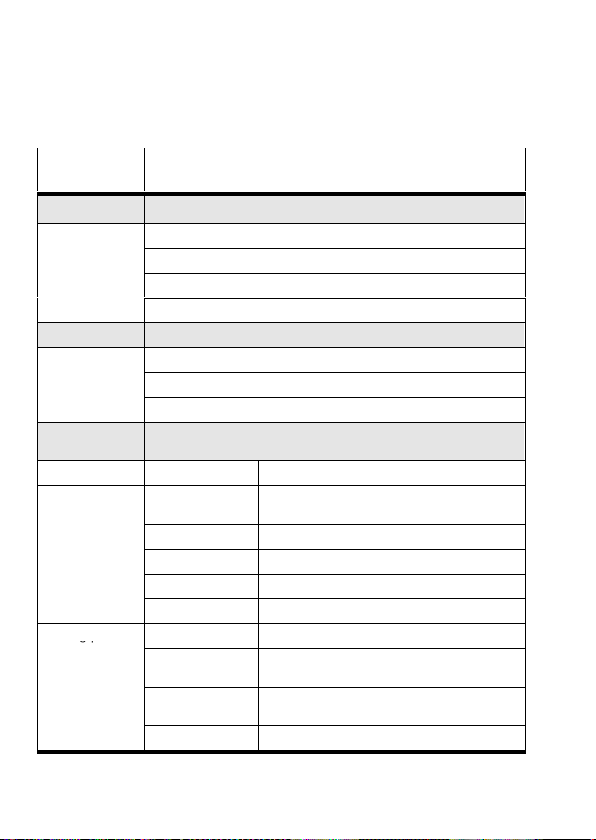
5 Struttura del menu (pannello di comando)
gp
Comando di
Descrizione
menu
Diagnostic Indicazione dati di sistema + impostazioni correnti
Pos. set table Indicazione tabella dei record di posizionamento
Axis param Indicazione parametri/dati dell’asse
System param Indicazione parametri/dati del sistema
SW information Indicazione versione del sistema operativo (firmware)
Positioning
Homing Avvio corsa di riferimento
Move posit set Avvio corsa di posizionamento record di posizionamento"
Demo posit tab Avvio corsa di posizion. tabella dei record di posizionamento"
Settings
Axis type HME−... Modulo lineare HME−...
Axis parameter Zero point
Homing paramet. Homing method Selezione del metodo di riferenziamento
1) 2)
Corsa di riferimento e corse di posizionamento per testare i record
1)
1) 2)
Selezione dell’attuatore, parametrazione, programmazione dei
record di posizionamento
3) 4)
Offset del punto zero dell’asse AZ dal punto di
riferimento
SW−limit−neg
SW−limit−pos
Tool load Massa dell’utensile (ades. pinza)
SAVE... Memorizzare parametri nell’EEPROM
Velocity v_rp Velocità di traslazione per la ricerca del punto
Velocity v_zp Velocità di traslazione per il posizionamento
SAVE... Memorizzare parametri nell’EEPROM
3) 4)
Fine corsa software, negativo; riferito a AZ
3) 4)
Fine corsa software, positivo; riferito a AZ
di riferimento
sul punto zero dell’asse
4)
4)
Festo P.BE−K−SFC−LAC−IO 0604NH Italiano60
Page 61
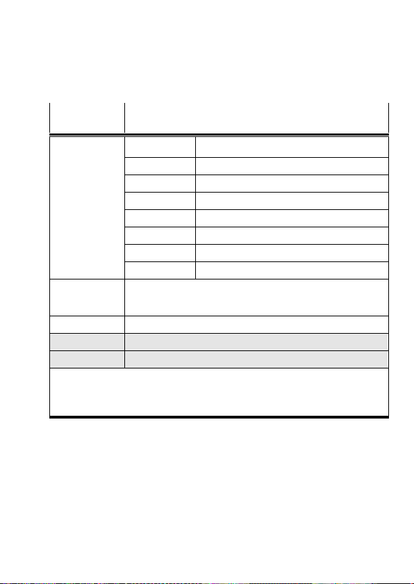
Comando di
Descrizione
menu
Position set Position nr Numero del record di posizionamento (1...31)
Pos set mode Modo: posizionamento assoluto o relativo
3) 4)
Position
Velocity Velocità di traslazione
Acceleration Accelerazione e ritardo
Jerk Scossa
Work load Carico utile
SAVE... Memorizzare parametri nell’EEPROM
Jog Mode Traslare l’attuatore tramite i tasti freccia (è possibile anche senza
una corsa di riferimento precedente; fine corsa software senza
funzione).
Password edit Predisposizione di una password per il pannello di comando
HMI control
1)
Impostazione del controllo dell’unità tramite pannello
LCD adjustment Rotazione dell’indicazione sul display di 180°
1)
Eventualmente protezione password
2
) Disattivare l’interfaccia di controllo, vedi [HMI control]:HMI = on
3)
Esercizio Teach
4)
Solo dopo la corsa di riferimento
Posizione di arrivo
Festo P.BE−K−SFC−LAC−IO 0604NH Italiano 61
Page 62

Festo P.BE−K−SFC−LAC−IO 0604NH Italiano62
Page 63
1 AnvändaranvisningarSvenska
Notera
Den här snabböversikten ingår i dokumentations−
paketet för typen P.BE−SFC−LAC−UDOK. Den innehåller
endast översiktsinformation och ersätter inte den
fullständiga manualen som finns som pdf−fil på den
medföljande CD−skivan (se tabell).
S Läs och följ all information och alla säkerhetstekniska
anvisningar i den fullständiga manualen till
motorcontrollern.
S Kontakta närmaste Festo−serviceavdelning eller skriv
till följande e−postadress vid
problem: [email protected]
eventuella tekniska
CD−skivans innehåll
Beskrivning av motorcontrollern
typSFC−LAC−...−IO
Installation och idrifttagning
Styrningsgränssnitt (I/O)
osv.
1)
= <artikelnummer> + <språkkod>.
Finns även i pappersversion med samma artikelnummer.
Festo P.BE−K−SFC−LAC−IO 0604NH Svenska 63
Språk Filnamn
Tyska
Engelska
Spanska
Franska
Italienska
Svenska
540547
540548
540549
540550
540551
540552
1)
d1
g1
e1
f1
i1
s1
Page 64

Ytterligare information finns här:
i hjälpsystemet till konfigurationsprogrammet Festo
Configuration Tool (FCT):
FCT help: funktionsbeskrivning FCT
SFC−LAC help: idrifttagning SFC−LAC
i den medföljande bruksanvisningen till respektive
komponent, t.ex. HME−...
Avsedd användning
Motorcontrollern SFC−LAC fungerar som positionerings−
styrning och lägesregulator för linjärmodulen HM E.
Den överordnade PLC/IPC ansluts vid typen SFC−LAC−...−IO
via digitala in−/utgångar.
Idrifttagning och parametrering av positionssatserna sker:
med
programmet FCT och plugin−programmet SFC−LAC
via RS232−gränssnittet eller
vid typ SFC−LAC−...−H2−... alternativt med hjälp av
manöverpanelen (display och 4 manöverknappar).
Festo P.BE−K−SFC−LAC−IO 0604NH Svenska64
Page 65
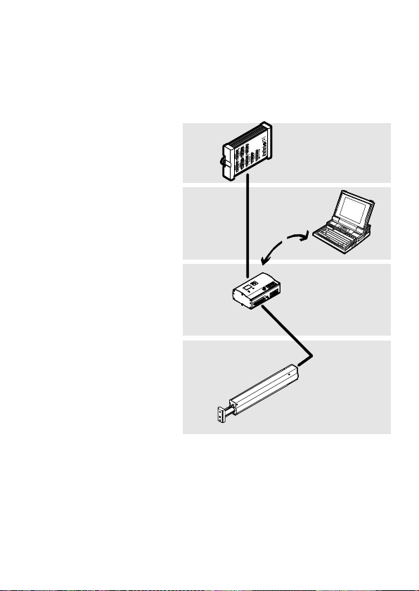
1 Överordnat
styrsystem, t.ex.
Festo typ FEC...
2 Programnivå: Festo
Configuration Tool
3 Controller−nivå:
SFC−LAC
4 Motor−drivenhets−
nivå: HME−...
1
2
3
4
Festo P.BE−K−SFC−LAC−IO 0604NH Svenska 65
Page 66
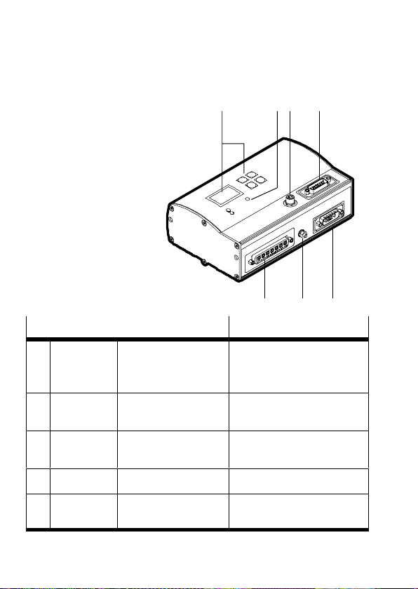
2 Indikerings− och anslutningselement
1 Manöverpanel
(endast typ
SFC−LAC−...−H2−...)
12 4
2 LED
3 Parametrering
4 Styrsystem
(PLC/IPC)
5 Spänningsmatning
6 Jordning (FE)
7 HME−...
Anslutning till SFC−LAC−...−I0 Beskrivning
Paramet−
3
rering
Styrsystem D−sub, 15−polig
4
Spännings−
5
matning
Jordning Stagbult M4 Funktionsjord (FE)
6
HME−... D−sub, 24W7
7
M8, 4−polig
Honkontakt
Kontakt
D−sub, 7W2
Kontakt
Honkontakt
RS232−gränssnitt för
parametrering, idrifttagning
och diagnos
Gränssnitt för anslutning till
ett PLC−styrsystem
Anslutning till
spänningsmatning
Gränssnitt för HME−...
3
567
Festo P.BE−K−SFC−LAC−IO 0604NH Svenska66
Page 67
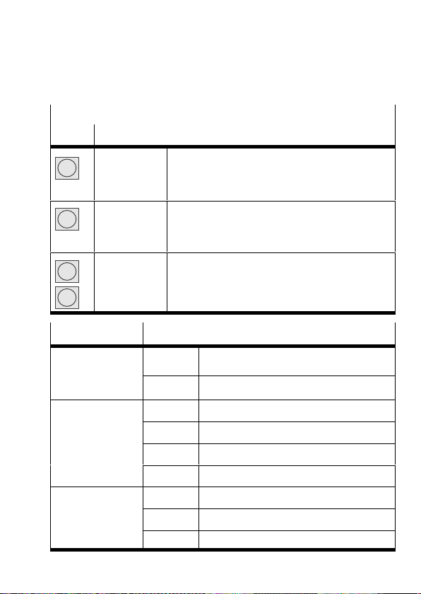
1 Manöverpanel (endast typ SFC−LAC−...−H2−...)
M
status
Knapp Funktion
Menu
Enter
v
V
MENU
ESC
EMERG.STOP
OK
SAVE
START/STOP
{ }
EDIT
Statusindikering > huvudmeny
Ångra inmatning eller gå tillbaka en menynivå
Avbryt aktuellt positioneringsförlopp
Aktiverar val resp. inmatning
Sparar parameterinställningar permanent
Startar/stoppar demo−läge
Föregående/nästa menykommando eller
manuell manövrering (inlärning)
Förminskar/förstorar parametervärdet
2 LED Status
Power
grön Matningsspänning ligger på
atnings−
spänning
I/F
Positionerings−
status
(tvåfärgs−LED)
släckt Ingen matningsspänning
grön Driftklar, aktivering föreligger
grön/röd Driftklar, aktivering saknas
släckt Positioneringsdrift eller fel/varning
röd Regulator−effektsteget frånkopplat
Error
Felindikering
röd Fel
blinkar Varning
släckt Inga interna fel indikerade
Festo P.BE−K−SFC−LAC−IO 0604NH Svenska 67
Page 68
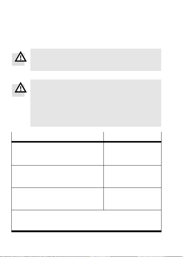
3 Anvisningar för montering och installation
Varning
Innan montering, installation och underhåll påbörjas
ska matningsspänningen till elektroniken kopplas bort.
Varning
När axeln monteras i snett och vertikalt läge fins det
risk för nedfallande massor!
S Kontrollera om externa säkerhetsåtgärder är
nödvändiga (t.ex. kugghake eller rörliga bultar).
På så sätt undviker du att arbetsmassan glider ned vid
strömavbrott.
*)
Spänningsmatning
Värde
Matningsspänning
Märkström (max. kontinuerlig ström)
Toppström
Logikmatning
Märkström / toppström
Intern säkring
I/O−matning
Tomgångsström / toppström
(per utgång max 0,5 A)
*)
Toleransena för matningsspänningen måste också upprätthållas
direkt vid anslutningarna på SFC−LAC.
**)
Ansluta massor för samma referenspotential.
**)
**)
48 VDC +5/−10%
10 A
20 A
24 VDC ±10%
0,4 A / 0,8 A
2,5A superflink
24 VDC ±10%
0,05 A / 2,1 A
Festo P.BE−K−SFC−LAC−IO 0604NH Svenska68
Page 69
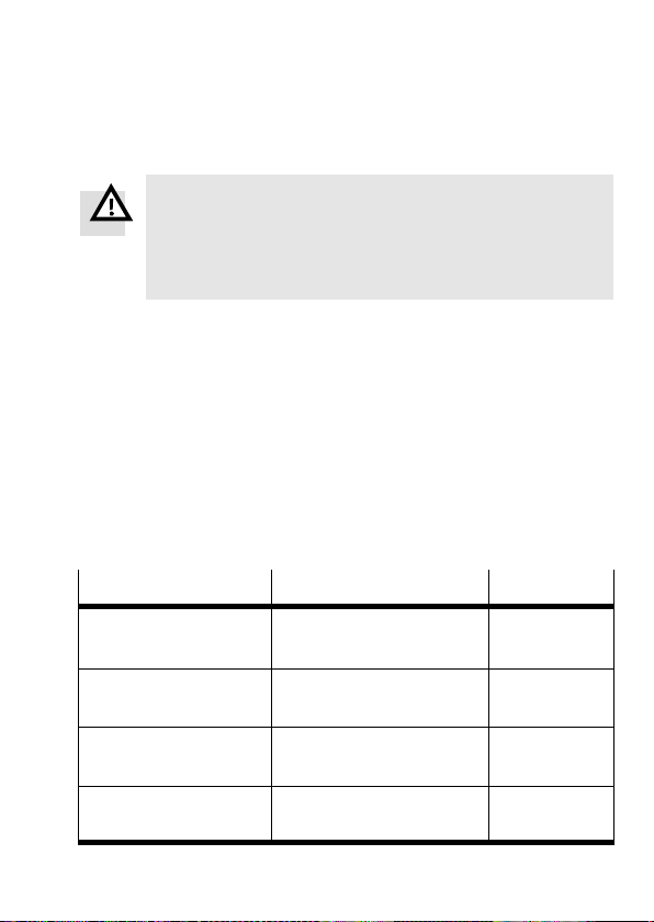
Varning
Använd endast strömkällor som garanterar en säker
isolering av matningsspänningen enligt IEC/DIN
EN60204−1. Observera dessutom allmänna krav på
PELV−kretsar enligt IEC/DIN EN 60204−1.
S Använd en reglerad nätdel.
S På följande sätt kan du undvika elektrostatisk
urladdning, och skyddsklass IP54 kan garanteras:
Förslut anslutningar som inte används med
medföljande skyddsplugg.
S För att undvika jordslingor: Använd
endast av en
jordanslutningarna (t.ex. 6).
S Använd endast den här kabeln (observera
maxlängden):
Kabel
Matningskabel (VDC) KPWR−MC−1−SUB−15HC−... 2,5 / 5 / 10
Motorkabel (HME) KMTR−LAC−S50HC−S50HC−... 2,5 / 5 / 10
Styrkabel (PLC) KES−MC−1−SUB−15−... 2,5 / 5 / 10
Programmeringskabel
(PC)
Festo P.BE−K−SFC−LAC−IO 0604NH Svenska 69
Tillbehör, typ ... Längd [m]
(max 10 m)
(max 10 m)
(max 30 m)
KDI−MC−M8−SUB−9−... 2,5
Page 70

4 Anvisningar för idrifttagning och drift
Varning
Elektriska axlar kan arbeta med stor kraft och hastighet.
Kollisioner kan leda till svåra personskador eller till att
komponenter förstörs.
S Se till att ingen uppehåller sig i området kring
axlarna eller kring andra anslutna arbetselement och
att inga föremål finns i rörelseområdet så länge
systemet är anslutet till en energikälla.
Varning
Skaderisk.
Fel i parametreringen kan leda till skador på personer
och föremål. I följande fall måste en referenskörning
genomföras för att baspunkternas och arbetsområdets
inställningar ska bli korrekta:
när enheten tas i drift för första gången,
efter att metoden för inställning av referensläge har
ändrats,
efter ändring av axelnollpunkten,
efter varje gång då logikspänningsmatningen
kopplas
till!
S Slutför idrifttagningen med Festo Configuration Tool
(se FCT−hjälpsystem) eller med manöverpanelen
(endast typ SFC−LAC−...−H2).
Festo P.BE−K−SFC−LAC−IO 0604NH Svenska70
Page 71

Översikt över första idrifttagning med manöverpanel
Före tillkoppling: Se till att inget ENABLE är aktivt på
1.
styrningsgränssnittet.
2. Koppla till SFC−LAC; välj drivenhetstyp (t.ex. HME−16−200).
3. Ställ in parametrar för referenskörning: Metod och
hastigheter.
4. Ställ in styrningsaktivering för manöverpanelen: [HMI = on].
Sökning efter kommuteringspunkten sker nu i några
sekunder (HME vibrerar).
5. Genomför referenskörning.
6. Läs in axelparameter: Axelnollpunkt AZ och program−
ändlägen (vid ändring av AZ: förnyad referenskörning).
7. Ange/lär in positionssatser.
8. Genomför provkörning. Kontrollera köregenskaper,
referenspunkter och arbetsområde.
9. Optimera vid behov positionssatser, referenspunkter och
arbetsområde.
10. Testa funktionen hos styrningsgränssnittet.
11. Observera driftanvisningarna vid avslutning av
idrifttagningen (se manualen till SFC−LAC−...).
Festo P.BE−K−SFC−LAC−IO 0604NH Svenska 71
Page 72
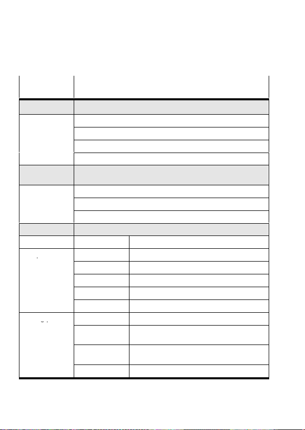
5 Menystruktur (manöverpanelen)
p
gp
Meny−
Beskrivning
kommando
Diagnostic Visa systemdata och aktuella inställningar
Pos. set table Visa positionssatstabell
Axis param Visa axelparametrar och −data
System param Visa systemparametrar och −data
SW information Visa operativsystemversion (fast programvara)
Positioning
Homing Starta referenskörningen
Move posit set Starta positioneringskörningen Position set"
Demo posit tab Starta positioneringskörningen Pos. set table"
Settings
Axis type HME−... Linjär modul HME−...
Axis parameter Zero point
Homing paramet. Homing method Val av metod för inställning av referensläge
1) 2)
Referenskörning och positioneringskörningar för test av
positionssatserna
1) 2)
Val av drivenhet, parametrering, programmering av positionssatser
3) 4)
SW−limit−neg
SW−limit−pos
Tool load Verktygsmassa (t.ex. gripare)
SAVE... Spara parameter i EEPROM
Velocity v_rp Rörelsehastighet för sökning efter
Velocity v_zp Rörelsehastighet för förflyttning till
SAVE... Spara parameter i EEPROM
3) 4)
3) 4)
1)
Axelnollpunktens AZ offset till referenspunkten
Programvaruändläge, negativt; relaterat till AZ
Programändläge, positivt; relaterat till AZ
referenspunkten
axelnollpunkten
4)
4)
Festo P.BE−K−SFC−LAC−IO 0604NH Svenska72
Page 73
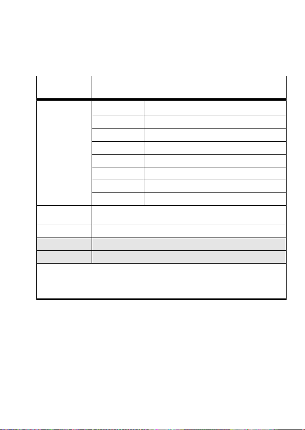
Meny−
Beskrivning
kommando
Position set Position nr Positionssatsens nummer (1...31)
Pos set mode Läge: absolut eller relativ positionering
3) 4)
Position
Velocity Reducera rörelsehastighet
Acceleration Acceleration eller fördröjning
Jerk Ryck
Work load Arbetslast
SAVE... Spara parameter i EEPROM
Jog Mode Förflytta drivenheten med hjälp av pilknapparna (möjligt även
utan föregående referenskörning)
Password edit Skapa ett lösenord för manöverpanelen
HMI control
1)
Ställa in styrningen via manöverpanelen
LCD adjustment Vrid indikeringen i displayen 180°
1)
Ev. lösenordsskydd
2)
Styrningsgränssnittet måste inaktiveras, se [HMI control]:HMI = on
3)
Teach−drift
4)
Endast efter att referenskörning har genomförts korrekt
Målposition
Festo P.BE−K−SFC−LAC−IO 0604NH Svenska 73
Page 74

Festo P.BE−K−SFC−LAC−IO 0604NH Svenska74
 Loading...