

Page 1
SFAH
Flow sensor
Festo AG & Co. KG
Ruiter Straße 82
73734 Esslingen
Germany
+49 711 347-0
www.festo.com
Instructions| Operating
8103751
2018-12a
[8103753]
8103751
Translation of the original instructions
1 About this document
This document describes the use of the above-mentioned product. Certain
aspects of use are described in other documents and must be observed
è 1.1 Applicable documents.
1.1 Applicable documents
5 Product overview
5.1 Design
All available documents for the product èwww.festo.com/pk.
Document Contents
Description of Flow Sensor SFAH Functional description, installation, commission-
IO-Link® IODD Device description file
ing, maintenance, description of the IO-Link®
parameters, technical data
Tab. 1
2 Safety
2.1 General safety instructions
– Only use the product in original status without unauthorised modifications.
– Only use the product if it is in perfect technical condition.
– Only use media in accordance with the specifications è Technical data.
– Observe the specifications on the product labelling.
– Installation, commissioning, maintenance and disassembly should only be
conducted by qualified personnel.
2.2 Intended use
The SFAH is intended for monitoring the flow rate of gaseous media in piping systems or terminals in the industry sector.
3 Further information
– Accessories èwww.festo.com/catalogue.
– Spare parts èwww.festo.com/spareparts.
4 Service
Contact your regional Festo contact person if you have technical questions
èwww.festo.com.
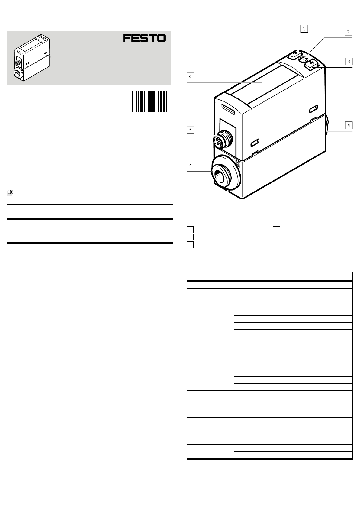
A-button
1
Edit button
2
B-button
3
Pneumatic connection (identifica-
4
tion on the product)
Plug for the electrical connection
5
Display
6
Fig. 1 Design of SFAH
5.1.1 Product variants and type code
Feature Value Description
Type SFAH Flow sensor
Flow measuring range
Pneumatic connection
Electrical output 1 -PNLK PNP or NPN or IO-Link®
Electrical output 2 -PNVBA PNP or NPN or 0…10V or 1…5V or 4…20mA
-0.1 Max. 0.1l/min
-0.5 Max. 0.5l/min
-1 Max. 1l/min
-5 Max. 5l/min
-10 Max. 10l/min
-50 Max. 50l/min
-100 Max. 100l/min
-200 Max. 200l/min
U UnidirectionalFlow input
B Bidirectional
-Q4 Push-in connector 4mm
-Q6 Push-in connector 6mm
-Q8 Push-in connector 8mm
-G18 Gx
-G14 G¼
NoneThread type
F Female thread
S StraightOutlet orientation
AR Angled, alignable
-L1 Plug L1Electrical connection
-M8 M8 plug
NoneCertificate
+T Test report
Tab. 2 Overview of variants
Page 2
5.2 Function
The SFAH measures the flow rate (standard flow rate, mass flow rate) with the
help of a thermal procedure. Measurements are carried out using a micromechanical sensor element with a downstream electronic evaluation unit. Connection to
higher-level systems is provided by 2switching outputs, an analogue output
and/or an IO-Link® interface. The outputs can be configured as appropriate to the
application. The switching outputs can be configured to monitor a threshold
value, signal range or signal change. The outputs can be set as PNP or NPN and
normally open (NO) or normally closed (NC). Through the IO-Link® interface, process values can be read out and parameters changed and transmitted to additional devices. Through integration of the flow rate, a volume/load signal can be calculated and output via a pulse output as well as a cumulated measurement value
through IO-Link®.
Fig. 2 SFAH signal structure
5.2.1 Operating statuses
Operating status Function
RUN mode – Basic status after the operating voltage is applied
SHOW mode – Display of current settings of the switching outputs and ana-
EDIT mode – Setting of parameters
TEACH mode – Acceptance of the current measured value to determine
– Display of the current measured value
– Display of the selected inputs and outputs
– Switchover between the measured variables of flow rate and
volume/mass
logue output
– Display and resetting of the minimum and maximum values
– Display of the average flow rate measurement
switching points
Tab. 3 Operating status of SFAH
5.2.2 Switching outputs
5.2.2.1 Switching functions
Threshold value comparator in the flow rate measurement for OutA or OutB
Function NO (normally open) NC (normally closed)
Switching function:
– 1 switching point (SP)
TEACH mode:
– 2 teach points (TP1, TP2)
Tab. 4 Threshold value comparator: setting of switching point [SP] and hysteresis
[HY]
Window comparator in the flow rate measurement for OutA or OutB
Function NO (normally open) NC (normally closed)
Switching function:
– 2 switching points (SP.Lo,
SP.Hi)
TEACH mode:
– 2 teach points (TP1, TP2)
– TP1 = SP.Lo, TP2 = SP.Hi
1)
Reference value qRef is determ-
1
ined
Measured value deviates by [d.SP]
2
from the reference value
Monitoring range
3
Fig. 3 Auto difference monitoring
The parameters [SP.Lo], [SP.Hi], [t.obS] and [d.SP] can be configured by the user.
The greater [t.obS] is set, the more stable the signal must be to establish the reference value qRef.
Function NO (normally open) NC (normally closed)
Switching function:
– 2 switching points (SP.Lo,
SP.Hi) for setting the valid
work range
– 1 switching point (d.SP)
for determination of the
monitoring area
TEACH mode:
– 2 teach points (TP1, TP2)
– TP1 = SP.Lo, TP2 = SP.Hi
1) SP.Lo = smaller signal value, SP.Hi = larger signal value, independent of the teach sequence
1)
Tab. 6 Window comparator: auto difference monitoring
5.2.2.2 Colour change
A red colour change can be set in the display for OutA and OutB, dependent on
the switching status. As a result, the switching status of the sensor can be identified over a large distance.
The colour change reacts both on OutA and on OutB, depending on the setting.
Parameter Meaning
bLUE Display is always blue; the colour change function is switched off.
R.On Display is red when the switching output is set (high = 1).
R.OFF Display is red when the switching output is not set (low = 0).
Display is blue when the switching output is not set (low = 0).
Display is blue when the switching output is set (high = 1).
Tab. 7 Colour change on the display
5.2.2.3 Volume/load pulse
A threshold value SP for the volume or load can be set in the accumulated
volume/load measurement. If the configured threshold value is reached, a switching impulse is emitted at the “Puls” output (è Fig.2) for an adjustable period of
time. With each switching impulse, the volume/load measurement is started
again (è Tab. 8 Volume/load pulse with accumulated volume measurement).
Setting NO (N/O (normally open) con
tact)
Setting NC (N/C (normally closed)
contact)
1) SP.Lo = smaller value, SP.Hi = larger value, independent of the teach sequence
Tab. 5 Window comparator: setting of switching points [SP.Lo] and [SP.Hi] and
hysteresis [HY]
Auto difference monitoring d_|¯|_
This function permits monitoring of a signal value for constancy. If the applied signal is constant in the range between [SP.Lo] and [SP.Hi], the reference signal qRef
is automatically determined. The result is a switching operation at the output and
signalises the start of the signal monitoring procedure. If the signal remains in the
monitoring range [d.SP] around qRef, the signal is stable. When the monitoring
range is left, the output switches back.
Tab. 8 Volume/load pulse with accumulated volume measurement
5.2.3 Zero point synchronisation
With zero point synchronisation (Zero Adjust), the offset error can be reset to
zero. This synchronisation affects the display and all outputs.
Page 3
5.2.4 Switchover of standard condition – REF / Cond
The represented flow rate and volume units can be related to different standard
conditions. It is possible to switch between the following standard conditions. In
the menu navigation on the display, the corresponding standard is determined by
selecting the reference temperature.
REF / Cond Off 15°C 20°C
Standard DIN 1343 ISO 2533 ISO 6358
Air pressure (absolute) [kPa] 101.325 101.325 100
Temperature [°C] 0 15 20
Humidity [%] 0 0 65
Status information “Option” Does not lightupLit Lit
Hrail mounting
Correction factor, measurement range limit value 1 1.055 1.087
Tab. 9 Standard conditions for flow rate and volume units
Calibration of the SFAH refers back to the physical standard conditions in accord-
ance with DIN1343.
If a standard other than DIN1343 is selected, the specified measurement range
(±100%FS)changes in value by the factor specified in
è Tab. 9 Standard conditions for flow rate and volume units. This change is visualised in the display through [Option].
Changing the reference standard only adjusts the display on the sensor. If necessary, the effect on the nominal measurement range of the respective sensor must
also be considered when evaluating the analogue output.
6 Assembly
Any mounting position is possible but can have an influence on measurement precision (è 14 Technical data).
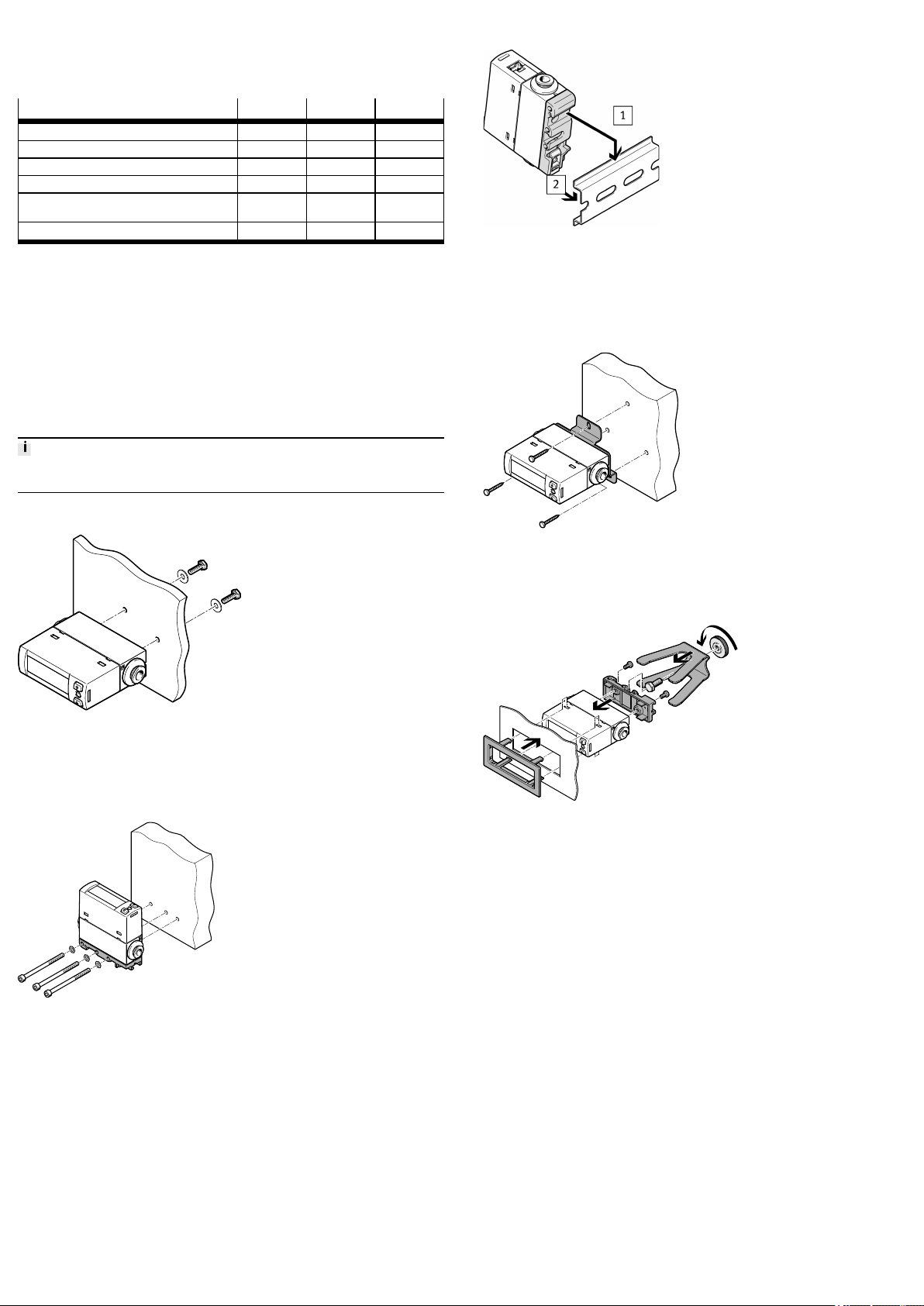
Plate mounting
Fig. 6 H-rail mounting
1. Mount H-rail mounting on the SFAH. Tightening torque 0.5Nm.
2. Hang H-rail mounting in the H-rail 1.
3. Press the H-rail mounting in the direction of the arrow until the mounting
slide catches 2.
Wall mounting
Fig. 7 Wall mounting
1. Screw wall mounting to SFAH. Tightening torque 0.5Nm.
2. Install wall mounting.
Front panel mounting kit (accessory)
Fig. 4 Plate mounting
• Secure the SFAH to the plate by using screws of suitable length.
– Hole diameter: max 3mm
– Tightening torque: 0.5Nm
Lateral plate mounting
Fig. 5 Lateral plate mounting
1. Mount H-rail mounting on the SFAH. Tightening torque 0.5Nm.
2. Mount H-rail mounting with washers and M4screws. Tightening torque
0.5Nm
Fig. 8 Front panel mounting kit
– Permissible front panel thickness: 1…3mm
1. Mount H-rail mounting on the SFAH. Tightening torque 0.5Nm.
2. Mount accompanying hexagon head screw on the H-rail mounting.
3. Push the panel frame through the cut-out (62mm x 24mm ± 0.1mm).
4. Push the sensor through the panel frame so that all 4 detent hooks engage.
5. Push the clamping element over the hexagon head screw.
6. Attach the sensor with the included knurled nut. Tightening torque 0.3Nm.
7 Installation
7.1 Pneumatic installation
• Mount the hoses to connection1 and connection2 (marking on the product).
SFAH-…U-…: If the tubing connection is incorrect, the measurement values are
presented with a minus sign and lie outside the specified measurement range.
SFAH-…B-…: The display of the flow direction with the correct sign can be set in
the Edit menu and shown in the sub-display.
Page 4
7.2 Inlet situation
The specified accuracies shown in the technical data of the sensor are achieved
when the conditions for the laminar flow inlet are observed on the sensor.
8 Commissioning
8.1 LCD display
diameter of
laminar flow
Design of
the laminar
flow inlet
Measuring rangeMin. internal
-0.1 -0.5 -1 -5 -10 -50 -100 -200
inlet in mm
2.9 (e.g.QS4) Any Permissible
4 (e.g.QS6) Straight
4 (e.g.QS6) Angle directly
4 (e.g.QS6) Angle at dis-
6 (e.g.QS8) Any Permissible
1) Accuracy as specified in the technical data
2) Deviation from the specified accuracy.
3) Operation possible. But deviations of more than20% must be expected.
on sensor
tance of
5…80cm
Permissible
1)
1)
1)
± 2%
2)
Not permissible
2)
± 1%
2)
± 10%
3)
Tab. 10 Effect of the inlet conditions and connection sizes on the specified accuracy
7.3 Electrical installation
WARNING!
Risk of injury due to electric shock.
• For the electrical power supply, use only PELV circuits in accordance with IEC
60204-1/EN 60204-1 (Protective Extra-Low Voltage, PELV).
• Observe the general requirements of IEC 60204-1/EN60204-1 for PELV circuits.
• Only use voltage sources that ensure a reliable electric separation from the
mains network in accordance with IEC 60204-1/EN 60204-1.
Long signal lines reduce the immunity to interference.
• Comply with the maximum permissible I/O signal line length of 30m (in IOLink® operation: 20m).
The binary outputs at pin 2 and pin 4 can be wired as PNP or NPN connections as
needed. Configure binary outputs according to your wiring in the [SPEC] menu
è 8.6 Configuring switching output (EDIT mode) and è Fig.12.
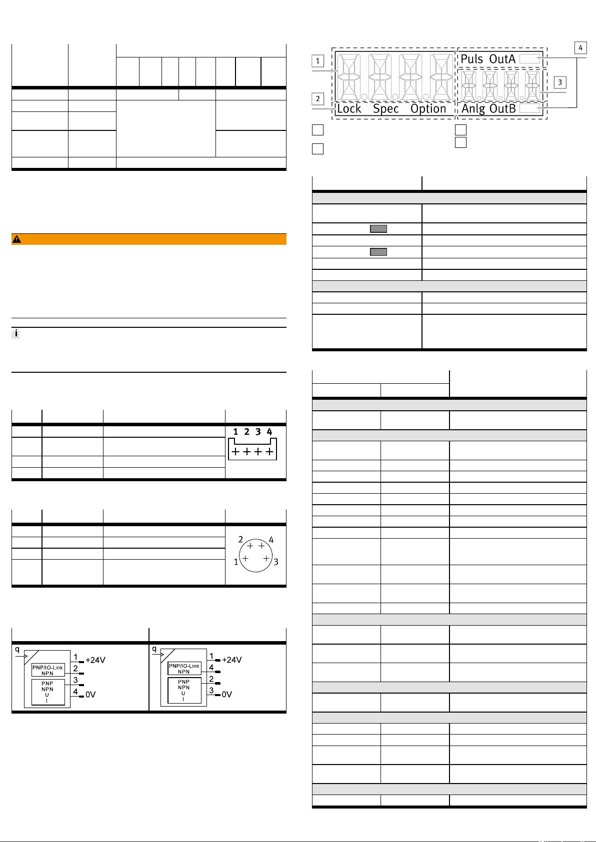
Pin Wire colour
1 Brown (BN) Operating voltage +24VDC
2 Black (BK) Switching output OutA, volume/load pulse
3 White (WH) Switching output OutB or analogue output
4 Blue (BU) 0V
1) Colours apply for connecting cables NEBS-L1...
1)
Allocation Plug L1
or IO-Link® (C/Q line)
Tab. 11 Pin allocation of plug L1
Pin Wire colour
1 Brown (BN) Operating voltage +24VDC
2 White (WH) Switching output OutB or analogue output
3 Blue (BU) 0V
4 Black (BK) Switching output OutA, volume/load pulse
1) Colours apply for connecting cables NEBU-M8...
1)
Allocation Plug M8x1
or IO-Link® (C/Q line)
Tab. 12 Pin allocation of plug M8x1
Circuit diagrams
SFAH…L1 SFAH…M8
Tab. 13 Circuit diagrams SFAH
Main display (e.g. measurement
1
value)
Status information
2
Lower display (e.g. unit)
3
Output display
4
Fig. 9 LCD display
Example for LCD display Meaning
Output display
[OutA] Switching output OutA selected/activated (flashes with
[OutA] Switching output OutA set
[OutB] Switching output OutB selected/activated
[OutB] Switching output OutB set
[Puls] Analogue output for volume/load pulse selected/activated
[Anlg] Analogue output for flow rate selected/activated
Status information / signal indicator
[Lock] Security code activated
[Spec] Special menu selected
[Option] Illuminates when parameters having a special influence on
active IO-Link®)
the measured value indicator have been changed (compared to the factory setting): reference condition (standard), gas
Tab. 14
Example for LCD display Meaning
Main display Lower display
Measured value indicator and unit in RUN mode
[–0.53] [L.Min] Measured value indicator (here: negative value)
Menu for the switching outputs (OutA and OutB)
[Edit] [bin] [OutA] / [OutB]: Edit menu for the switching out-
_|¯ [Fctn] Threshold value comparator
_|¯|_ [Fctn] Window comparator
d_|¯|_ [Fctn] Auto difference monitoring
[18.0] [SP] Switching point value
[1.80] [SP.Lo] Value of lower switching point
[6.45] [SP.Hi] Value of upper switching point
[0.50] [HY] Hysteresis value
[18] [t.obS] / [MSEC] Time interval for determination of the signal
[0.25] [d.SP] Threshold value for determining the monitoring
[NO] [LOGC] Switching characteristics: [NO] = normally open
[bLUE] [COLR] Display colour
Extreme values (only SHOW mode)
[1.64] [MIN] Minimum measured value since switch-on of the
[8.50] [MAX] Maximum measured value since switch-on of the
[20.8] [AVER] Average of the flow rate measurement, filter time
Additional settings (pulse at the output)
[100] [PULSE] Duration of the volume or load pulse at the out-
Analogue output
[Edit] [ANLG] Edit menu for the analogue output
[0...10] [Out] / [V] Output function of the analogue output
[100] [In.Hi] / [%] Scaling of the analogue output to the end value
[-100] [In.Lo] / [%] Scaling of the analogue output to the start value
Menu for device settings (Spec)
[Edit] [Menu] [Spec]: Edit menu for additional settings
and unit
puts (binary)
change, which is used to establish the reference
value.
area
contact, [NC] = normally closed contact
supply voltage or the last reset
supply voltage or the last reset
constants
put
of the flow measuring range in percent of FS
of the flow measuring range in percent of FS
Page 5
Example for LCD display Meaning
Main display Lower display
[16] [Filt] / [MSEC] Value of the filter time constant for the measure-
[L.Min] [FLOW Unit] Display unit for flow rate measurement
[0°C] [REF] / [Cond] Reference standard for gas volume
[Air] [GAS] Selection of the operating medium
[1->2] [FLOW] / [Path] Selection of the flow direction from Port 1 to 2 or
[ON] [Z.Adj] Offset synchronisation for display, switching and
[Unit] [Sub.d] Settings of the lower display in RUN mode: selec-
[40] [Eco] / [SEC] Economy mode: period after which the display
[PNP] [bin] / [Out] Shift of the switching outputs (binary) between
[Flow] [bin] / [Pin4] Shift of binary switching output or pulse output.
[bin] [FLOW] / [Pin2] Shift of binary switching output or analogue out-
[OFF] [Code] Activation and determination of the security
[OFF] [MASt] Activation of the IO-Link® master function for
ment signal
vice versa (only for bidirectionally calibrated
product variant)
analogue output
ted unit or switching point of OutA or bar graph
or gas or flow direction
background lighting is switched off
PNP and NPN
Pin4 with M8 variant, pin2 with L1 variant
put to pin2 in M8 variant, pin3 with L1 variant
code
replication of parameters
Tab. 15
8.2 Switch on sensor (RUN mode)
• Switch on the operating voltage.
Current measured value is displayed. The sensor is in the basic status
Ä
(RUN mode).
The basic static can be established using the following actions:
– Press the Edit button for 3 seconds
– Expiration of a monitoring time (timeout)
8.3 Switchover of measured value indicator
• Switchover to flow rate measurement: press A pushbutton.
• Switchover to volume measurement: press B pushbutton.
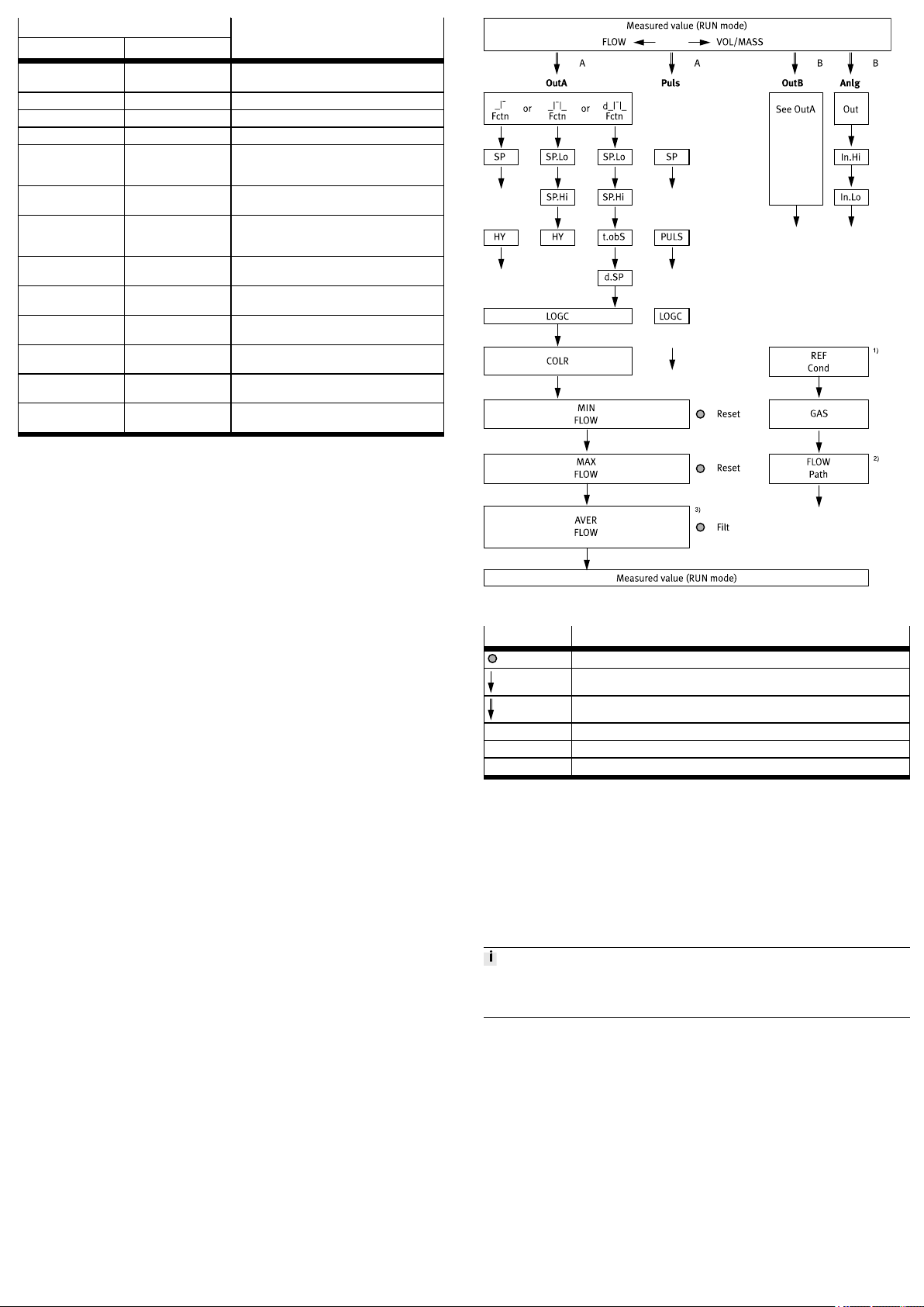
8.4 Displaying parameters (SHOW mode)
Requirement: The sensor is ready for operation (RUN mode).
Switching output OutA or volume pulse output
1. Press the A pushbutton twice.
The first parameter set is displayed. [Fctn] flashes for OutA or [SP] flashes
Ä
for “Puls”.
2. To display each of the following parameters, press the A pushbutton
(è Fig.10).
The averaged flow rate value [AVER] is displayed at the end.
Switching output OutB or analogue output Anlg
1. Press B pushbutton
The first parameter set is displayed. [Fctn] flashes for OutB or [Out]
Ä
flashes for Anlg.
2. To display each of the following parameters, press the A pushbutton
(è Fig.10).
For bidirectional product variant SFAH-...B-..., the flow direction [Path] is displayed at the end.
Fig. 10 Measured value indicator (RUN mode)
Legend Meaning
Edit button
A or B pushbutton
Double-press the A or B pushbutton
1) Not for flow unit G.Min
2) Only for bidirectional product variant
3) Selectable values: 256, 512, 1024ms
Tab. 16 Legend for measured value indicator (RUN mode)
8.5 Enter the security code (EDIT mode)
Requirement: The sensor is ready for operation (RUN mode).
1. Press the Edit button.
The EDIT mode is active. If the security code is activated, the parameter
Ä
entry option is blocked: [Lock] flashes.
2. Enter the set security code using the A or B pushbutton.
3. Press the Edit button briefly.
[OutA] flashes. The parameter entry option is unblocked.
Ä
8.6 Configuring switching output (EDIT mode)
The process is the same for configuring the switching outputs for [OutA] and
[OutB.] In the following, the process is described using the switching output OutA.
Menu structure è 8.12 Menu structure (EDIT mode).
Requirement: The sensor is ready for operation (RUN mode).
1. Press the Edit button briefly.
[Edit] appears. [OutA] flashes.
Ä
2. Press the Edit button briefly.
[Fctn] flashes.
Ä
3. Select switching function _I¯ or _I¯I_ or d_I¯I_ with the A or B button.
4. Press the Edit button briefly.
The set value is saved. The next adjustable parameter is shown.
Ä
5. Set the parameter with A or B pushbutton.
6. Repeat steps 4 and 5 until all parameters are set (switching functions
è 5.2.2.1 Switching functions).
Page 6
8.7 Change device settings (EDIT mode)
Requirement: The sensor is ready for operation (RUN mode).
1. Press the Edit button briefly.
[Edit] appears. [OutA] flashes.
Ä
2. Select the Special menu [Spec] using the A or B pushbutton.
[Spec] flashes.
Ä
3. Press the Edit button briefly.
[Filt] / [MSEC] flashes.
Ä
4. Set the parameter with A or B pushbutton.
5. Press the Edit button briefly.
The set value is saved. The next adjustable parameter is shown.
Ä
6. Repeat steps 4 and 5 until all parameters are set.
8.8 Setting the volume pulse output (EDIT mode)
Requirement: The sensor is ready for operation (RUN mode).
1. Press the Edit button briefly.
[Edit] appears. [OutA] flashes.
Ä
2. Select [Puls] using the A or B pushbutton.
3. Press the Edit button briefly.
[SP] / [Volume Unit] flashes.
Ä
4. Set the parameter with A or B pushbutton.
5. Press the Edit button briefly.
The set value is saved. The next adjustable parameter is shown.
Ä
6. Repeat steps 4 and 5 until all parameters are set.
8.9 Set analogue output (EDIT mode)
Requirement: The sensor is ready for operation (RUN mode).
1. Press the Edit button briefly.
[Edit] appears. [OutA] flashes.
Ä
2. Select [Anlg] using the A or B pushbutton.
3. Press the Edit button briefly.
[Out] / [V] flashes.
Ä
4. Set the parameter with A or B pushbutton.
5. Press the Edit button briefly.
The set value is saved. The next adjustable parameter is shown.
Ä
6. Repeat steps 4 and 5 until all parameters are set.
8.10 Replicating parameters (EDIT mode)
Requirement:
– The pre-configured master sensor is ready for operation (RUN mode).
– Master sensor and device sensor have the same design regarding the para-
meters (same device ID).
– The master sensor is connected with the device sensor è Fig.11.
– Parameterisation of the device sensor must not be blocked via IO-Link®.
– The device sensor is in an unswitched status (switching output PNP, display
OutA off).
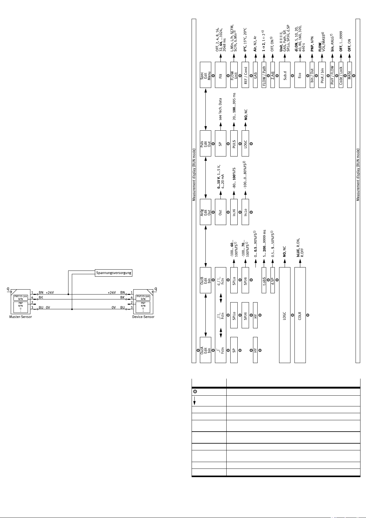
8.12 Menu structure (EDIT mode)
Fig. 11 Example of pin allocation SFAH-...M8
1. Select the Special menu [Spec] on the master sensor through the device set-
tings.
2. Press the Edit button briefly several times until [MASt] appears.
3. Select [ON] using the A or B pushbutton.
4. Press the Edit button.
[REPL] / [RedY] appears.
Ä
5. Press A or B pushbutton.
[REPL] / [RUN] appears briefly. The parameters are transmitted to the
Ä
device sensor. [REPL] / [RedY] appears. If an error occurs, an error message appears è 11 Fault clearance.
6. Repeat point 5 if an additional sensor should be parameterised.
7. Press the Edit button briefly.
Switch to the RUN mode.
Ä
8.11 Configuring the sensor (EDIT mode)
shows the complete menu structure. Some menu options or setting values are not
applicable, depending on the product variant and the selected switching function.
Fig. 12 Menu structure of Edit mode
Legend Meaning
Edit button
A or B pushbutton
Bold Factory setting
1) The values refer to the respective measuring range and selected unit
2) Factory setting –100 for bidirectional variant; factory setting 0 for unidirection-
3) Factory setting l/h for measurement ranges 0.1l/min and 0.5l/min; factory
4) Menu option only for bidirectional variant
5) Factory setting OFF for unidirectional variant; factory setting ON for bidirection-
6) For M8 plug: pin4; for L1 plug: pin2
7) For M8 plug: pin2; for L1 plug: pin3
al variant
setting l/min for all other measurement ranges
al variant
Tab. 17 Legend for menu structure
Page 7
8.13 Teach switching points (TEACH mode)
The Teach process is the same for configuring the switching outputs for OutA and
OutB. In the following, the process is described using the switching output OutA.
The Teach function is only available for flow monitoring.
Requirement: The sensor is ready for operation (RUN mode).
If the security code is activated, the parameter entry option is blocked: [Lock]
flashes.
1. Enter the security code è 8.5 Enter the security code (EDIT mode).
2. Establish the switching function in EDIT mode
è 8.6 Configuring switching output (EDIT mode).
3. Apply signal value 1.
4. Press the A pushbutton and Edit button.
The current signal value will then be adopted as the first Teach point
Ä
(TP1). [t-IN] flashes.
5. Apply signal value 2.
6. Press the A pushbutton and Edit button.
The current signal value will then be adopted as the first Teach point
Ä
(TP2). Switch to the RUN mode.
8.14 Zero point synchronisation (Zero Adjust)
Requirement:
– The sensor is ready for operation (RUN mode).
– The operating pressure is present, but no flow rate exists.
– [Z.AdJ] is set to [ON] (è 8.7 Change device settings (EDIT mode)).
– The measured value lies in the range 0l/min ±3%FS.
• Press the A and B pushbuttons and Edit button simultaneously.
– If [OK] appears: the zero point synchronisation was successful.
Ä
– If [FAIL] appears: the zero point synchronisation was not successful.
Check requirements.
Fault description Cause Remedy
[Er20] / [t.Hi]
[Er21] / [SHRt]
[Er22] / [SHRt]
[Err] / [bUSY] OutA/“Puls” is switched active
[Err] / [Id] Device ID error, devices do not
[Err] / [COM] IO-Link® communication error – Check settings of the
1) Display flashes red
2) Display illuminates red
2)
2)
2)
Temperature fault – Check operating condi-
Short circuit at OutA/“Puls” Eliminate short circuit
Short circuit at OutB Eliminate short circuit
in the device sensor
have the same design
tions
– Check ambient temperat-
ure
– Check wiring
– Replace device
Check device settings
When replicating, use sensor
with the same type flow rate
measurement range (same
device ID)
device sensor
– Check line
Tab. 18
12 Disassembly
1. Turn off energy source and compressed air.
2. Separate connections from the sensor.
3. Loosen the mountings.
13 Disposal
ENVIRONMENT!
Send the packaging and product for environmentally sound recycling in accordance with the current regulations èwww.festo.com/sp.
If [Z.AdJ] [OFF] is set for a later time, the sensor takes over the factory setting calibration values.
9 Operation and use
After the supply voltage is switched on, the SFAH needs a warm-up time of
10minutes until it achieves the specified accuracy.
The flow rate displayed by the SFAH refers to the standard conditions that were
set under Options in the Special menu.
9.1 Restoring factory settings (restore)
By resetting to the factory settings, the current settings are lost. If required, make
a note of these settings before resetting.
1. Switch off operating voltage.
2. Keep the A and B pushbuttons pressed down simultaneously.
3. Switch on the operating voltage.
4. Additionally, press the Edit button.
[RSto PArM] appears. All parameters are reset to the factory settings.
Ä
10 Maintenance and care
1. Turn off energy source and compressed air.
2. Clean sensor with non-abrasive cleaning agents.
11 Fault clearance
Fault description Cause Remedy
No display
Indicator or switching output
does not react as expected
[Er01] / [FAIL]
[Er02] / [ASIC]
[Er03] / [SEnS]
[Er09] / [UndR] Below sensing range Maintain sensing range
[Er10] / [OVER] Sensing range exceeded Maintain sensing range
[Er17] / [SUPL]
1)
1)
1)
2)
No operating voltage or impermissible operating voltage
Electrical connections swapped Connect the device in accord-
Device defective Replace device
Eco mode on Press pushbutton or switch off
Short circuit or overload at the
output
Incorrect switching point taught
(e.g.at 0l/min)
Incorrect standard condition set
for volumetric flow rate
Device defective Replace device
Parameter incorrect Reset to factory settings.
Device defective Replace device
Device defective Replace device
Device defective Replace device
Undervoltage Maintain permissible operating
Apply permissible operating
voltage.
ance with the circuit diagram.
Eco mode
Eliminate short circuit/overload.
Repeat teaching.
Correct standard condition
voltage
14 Technical data
General
Approvals RCM compliance mark
CE marking (declaration of conformity
èwww.festo.com/sp)
Information on materials RoHS-compliant
In accordance with EU EMC Directive
In accordance with EU RoHS Directive
Tab. 19 General
Input signal/measuring element
Measured variable Volumetric flow rate, mass flow rate
Flow direction Unidirectional, bidirectional
Measuring principle Thermal
Warm-up time [min] 10
Method of measurement Heat transfer
Operating pressure [bar] –0.9…10
Operating pressure [kPa] –90…1000
Operating medium Compressed air according to ISO 8573-1:2010 [6:4:4],
Temperature of medium [°C] 0…50
Ambient temperature [°C] 0…50
Nominal conditions for determination of
the accuracy specification.
nitrogen, argon
– Operating pressure at output: 0kPa relative
– Medium and ambient temperature:23°C
– Analogue output: voltage with 20kΩ load
– Switching output: load current in the switched
status 5mA
– Mounting position: horizontal, display upwards
– Inflow: è 7.2 Inlet situation
Tab. 20 Input signal/measuring element
Flow rate measuring
0.1 0.5 1 5 10 50 100 200
range [l/min]
Start value 0.002 0.01 0.02 0.1 0.2 1 2 4
End value 0.1 0.5 1 5 10 50 100 200
Tab. 21 Flow rate measuring range unidirectional or bidirectional
Flow rate measuring
0.1B 0.5B 1B 5B 10B 50B 100B 200B
range [l/min]
Start value –0.002 –0.01 –0.02 –0.1 –0.2 –1 –2 –4
End value –0.1 –0.5 –1 –5 –10 –50 –100 –200
Tab. 22 Flow rate measuring range bidirectional, additional
Page 8
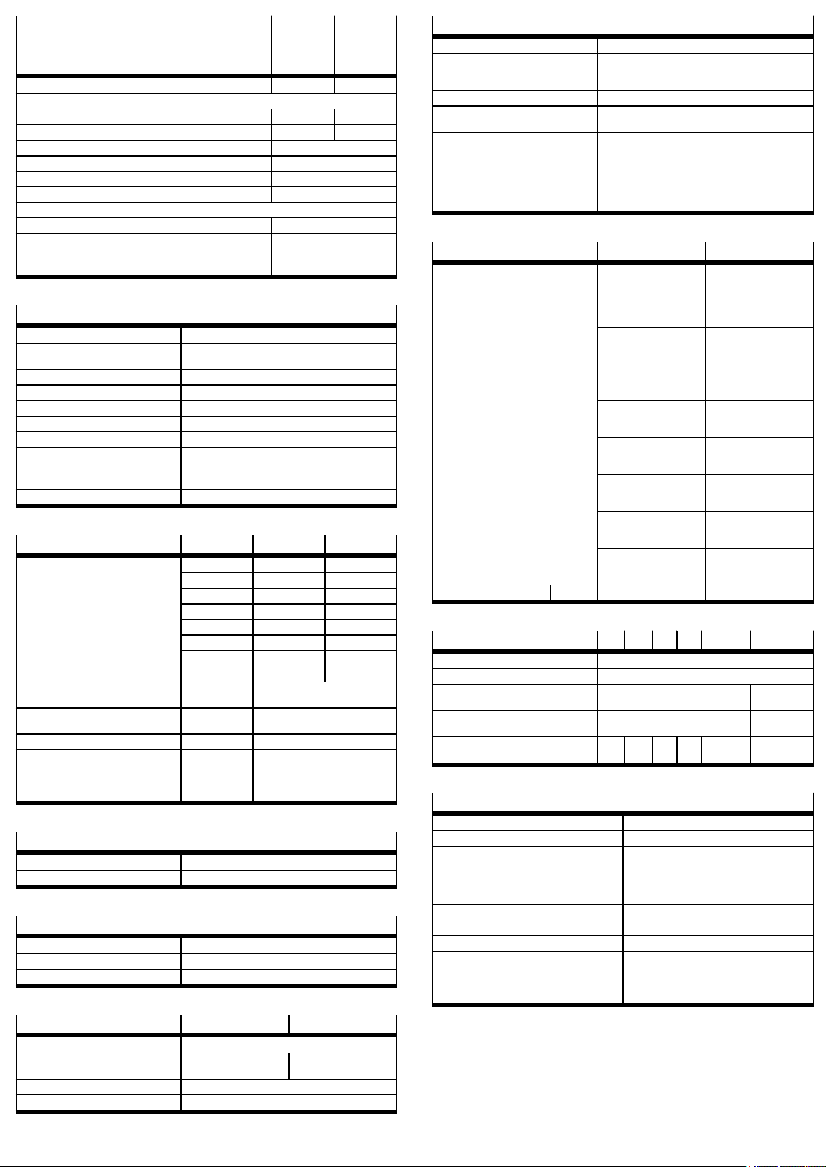
Output, general Com
Argon
pressed
air, nitro
gen
Accuracy of zero point [% FS] ±1 ±2
Accuracy of margin
– Without use of current output [% FS] ±2 ±4
– With use of current output [% FS] ±3.5 ±7
Repetition accuracy of zero point [% FS] ±0.2
Repetition accuracy of margin [% FS] ±0.8
Temperature coefficient of margin [% FS/K] Typ. 0.15 (max. 0.3)
Temperature coefficient zero point [% FS/K] Typ. 0 (max. 0.05)
Pressure influence of margin
– In a pressure range of –70…+1000kPa [% FS] Typ. ±1
– In a pressure range of –90…–70kPa [% FS] Typ. ±4
Position dependency of zero point with vertical installation
[% FS/100kPa] ±0.5
Tab. 23 Output, general
Switching output
Switching output 2x PNP or 2x NPN, switchable
Switching function Threshold value comparator, window comparator, auto
Switching element function N/C contact or N/O contact, switchable
Switch-on time [ms] Max. 6 (for Filt = OFF)
Switch-off time [ms] Max. 5 (for Filt = OFF)
Max. output current [mA] 100
Voltage drop [V] Max. 1
Pull-down resistor [ms] PNP: integrated
Pull-up resistor [ms] NPN: not integrated (load current of at least 2mA
Inductive protective circuit Available
difference monitoring
required)
Tab. 24 Switching output
Analogue output Variant ...U ...B
Characteristic flow rate curve [l/min]
Output characteristic curve
for voltage
Output characteristic curve
for current
Rise time [ms] All Max. 3 (for Filt = Off)
Max. load resistance of current output
Min. load resistance of
voltage output
[V] All 0…10 or 1…5
[mA] All 4…20
[Ω] All 500
[kΩ] All 20
-0.1..- 0…0.1 –0.1…0.1
-0.5..- 0…0.5 –0.5…0.5
-1..- 0…1 –1…1
-5..- 0…5 –5…5
-10..- 0…10 –10…10
-50..- 0…50 –50…50
-100..- 0…100 –100…100
-200..- 0…200 –200…200
Tab. 25 Analogue output
Output, additional data
Short circuit current rating Yes
Overload protection Available
Tab. 26 Output, additional data
Electronics
Operating voltage range [VDC] 22…26
Idle current [mA] Max. 25
Reverse polarity protection For all electrical connections
Tab. 27 Electronics
Electromechanics M8 L1
Connection type Plug
Connection technology M8x1 A-coded according
Number of pins/wires 4
Max. connecting cable length [m] 30 (20 for IO-Link® operation)
to EN61076-2-104
L1J
Tab. 28 Electromechanics
Mechanics
Mounting position Any
Pneumatic connection è Tab. 2 Overview of variants,
Product weight [g] Approx. 90
Information on housing
materials
Materials in contact with
medium
è Tab. 10 Effect of the inlet conditions and connection
sizes on the specified accuracy
Reinforced polyamide
– NBR
– PA-reinforced
– High-alloy stainless steel
– Anodised wrought aluminium alloy
– Silicon
– Silicon nitride
– Epoxy
Tab. 29 Mechanics
Display/operation Variant
Displayable units
Setting range, threshold value volume
Zero range hiding [%FS] All < 1.5 (Z.Adj = OFF)
-0.1
-0.5
-1
-5
-10
-50
-100
-200
-0.1 0.001…9.999l;
-0.5
-1
-5 0.1…999.9l;
-10 0.1…999.9l;
-50 1…9999l;
-100
-200
l/min, l/h, scft/h, g/min, l,
scft, g
l/min, l/h, scft/min, scft/h,
g/min, l, scft, g
l/min, scft/min, scft/h,
g/min, l, scft, g
0.001…9.999sft3;
0.001…9.999g
0.01…99.99l;
0.001…9.999sft3;
0.01…99.99g
0.001…9.999sft3;
0.1…999.9g
0.01…99.99sft3;
0.1…999.9g
0.01…99.99sft3;
1…9999g
1…9999l;
0.1…999.9sft3;
1…9999g
Tab. 30 Display/operation
Immissions/emissions 0.1 0.5 1 5 10 50 100 200
Storage temperature [°C] –20…80
Degree of protection IP40
Pressure drop at 600kPa at
input and q max.
Pressure drop at 0kPa at
output and q max.
Standard nominal flow rate
(600 -> 500kPa)
[kPa] < 0.5 1.2 1.5 1.6
[kPa] < 0.5 7.5 10 30
[l/min] 57 93 121 361 445 458 490 870
Tab. 31 Immissions/emissions
IOLink®
Protocol version Device V1.1
Device V1.1 Smart sensor profile
Function classes Binary data channel (BDC)
Communication mode COM2 (38.4 kbaud)
Port class A
Process data width IN 3 bytes
Process data content IN 2 bit BDC (flow rate monitoring)
IODD, IO-Link® device description èwww.festo.com/sp
Process data variable (PDV)
Identification
Diagnostics
Teach channel
1bit BDC (volume monitoring)
14bit PDV (measured flow rate value)
Tab. 32 IO-Link®
 Loading...