

Page 1
Motor unit
MTR-DCI
Description
MTR-DCI-...-CO
Description
539630
en 1209a
[763213]
Page 2

Adobe®, Reader®,CANopen®and CiA®are registered brand
names of the respective brand holders in certain countries.
Page 3

Contents and general safety instructions
Original de.......................................
Edition en 1209a..................................
Designation P.BE-MTR-DCI-CO-EN.....................
Order-no. 539630..................................
© Festo AG & Co. KG, D-73726 Esslingen, 2012
Internet: http://www.festo.com
E-mail: [email protected]
Reproduction, distribution or sale of this document or
communication of its contents to others without express
authorization is prohibited. Offenders will be liable for damages. All rights reserved in the event that a patent, utility
model or design patent is registered.
Festo P.BE-MTR-DCI-CO-EN en 1209a
I
Page 4

Contents and general safety instructions
II
Festo P.BE-MTR-DCI-CO-EN en 1209a
Page 5

Contents and general safety instructions
Designated use IX........................................................
Safety instructions X.....................................................
Target group XI..........................................................
Service XI...............................................................
Scope of delivery XI.......................................................
Important user instructions XII..............................................
Manuals on motor unit type MTR-DCI XIV......................................
Informationontheversion XV...............................................
Product-specific terms and abbreviations XVI...................................
CANopen specific terms and abbreviations XVIII..................................
1. System overview 1-1...............................................
1.1 Positioning with electric drives 1-3....................................
1.2 Field bus communication 1-6.........................................
1.2.1 Data exchange in CANopen 1-6...............................
1.2.2 Data profiles FHPP and CiA 402 1-7............................
1.3 Components 1-10...................................................
1.4 Control and regulating functions 1-11...................................
1.5 Operational safety 1-13..............................................
1.6 Measuring reference system 1-15......................................
1.6.1 Reference points and positioning range 1-15.....................
1.6.2 Signs and directions 1-17.....................................
1.6.3 Reference run (homing) 1-19..................................
2. Mounting 2-1.....................................................
2.1 General instructions 2-3.............................................
2.2 Dimensions of the motor unit 2-4.....................................
2.3 Fitting electric axes 2-5..............................................
Festo P.BE-MTR-DCI-CO-EN en 1209a
III
Page 6

Contents and general safety instructions
3. Installation 3-1...................................................
3.1 Overview of installation 3-3..........................................
3.2 Earthing 3-6.......................................................
3.3 Power supply 3-7..................................................
3.3.1 Requirements of the power supply 3-7.........................
3.3.2 Load and logic voltages 3-8...................................
3.4 Serial interface 3-11.................................................
3.5 Input for external reference switch 3-13.................................
3.6 Controller 3-15.....................................................
3.7 Connecting the field bus 3-18.........................................
3.7.1 Field bus cable 3-18..........................................
3.7.2 Fieldbus bit rate and fieldbus length 3-19........................
3.7.3 Bus termination with terminating resistors 3-20...................
4. Control panel (only type MTR-DCI-...-H2) 4-1...........................
4.1 Composition and function of the control panel 4-4.......................
4.2 The menu system 4-6...............................................
4.2.1 Accessing the main menu 4-6.................................
4.2.2 Selecting a menu command 4-6...............................
4.3 [Diagnostic] menu 4-8..............................................
4.4 [Positioning] menu 4-11..............................................
4.4.1 [Positioning] [Move position set] 4-12...........................
4.4.2 [Positioning] [Demo position table] 4-13.........................
4.4.3 [Positioning] [Homing] 4-14....................................
4.5 Menu [Settings] 4-16................................................
4.5.1 [Settings] [Axis type] 4-17.....................................
4.5.2 [Settings] [Axis parameter] 4-18................................
4.5.3 [Settings] [Homing paramet.] 4-19..............................
4.5.4 [Settings] [Position set] 4-20...................................
4.5.5 [Settings] [Password edit] 4-21.................................
4.5.6 [Settings] [CAN parameters] 4-23...............................
4.6 Menu command [HMI control] 4-25.....................................
IV
Festo P.BE-MTR-DCI-CO-EN en 1209a
Page 7

Contents and general safety instructions
5. Commissioning 5-1................................................
5.1 Procedure for commissioning 5-4.....................................
5.2 Commissioning with the control panel (only MTR-DCI-...H2) 5-7.............
5.2.1 Setting the axis type 5-9.....................................
5.2.2 Setting the reference travel parameters 5-10.....................
5.2.3 Starting a reference run 5-13..................................
5.2.4 Teach the axis zero point AZ and the software end positions 5-16.....
5.2.5 Teach position records 5-18...................................
5.2.6 Test run 5-20...............................................
5.2.7 Setting CAN parameters 5-22..................................
5.3 Commissioning with FCT 5-26.........................................
5.3.1 Installing the FCT 5-27........................................
5.3.2 Procedure 5-28.............................................
5.4 CommissioningonaCANopenmaster 5-30..............................
5.4.1 Overview of commissioning on the field bus 5-31..................
5.4.2 Configuration of the CANopen master (“I/O configuration”) 5-32.....
5.4.3 Communication 5-33.........................................
5.4.4 PDO mapping 5-34...........................................
5.5 Festo profile for handling and positioning (F HPP standard) 5-37.............
5.5.1 Supported operating modes 5-37...............................
5.5.2 Composition of the cyclic I/O data (FHPP standard) 5-39............
5.5.3 Description of the I/O data (Record select) 5-41...................
5.5.4 Description of the I/O data (Direct mode) 5-42....................
5.5.5 Description of the control bytes CCON, CPOS, CDIR 5-43............
5.5.6 Description of the status bytes SCON, SPOS, SDIR (RSB) 5-46.......
5.5.7 Examples of the I/O data 5-49.................................
Festo P.BE-MTR-DCI-CO-EN en 1209a
V
Page 8

Contents and general safety instructions
5.6 Sequence control as per FHPP standard 5-62............................
5.6.1 Homing 5-62................................................
5.6.2 Jog mode 5-64..............................................
5.6.3 Teaching via field bus 5-66....................................
5.6.4 Record select (positioning mode) 5-68...........................
5.6.5 Direct mode (positioning mode, power operation) 5-74.............
5.6.6 Standstill monitoring 5-81.....................................
5.7 Notes on operation 5-83..............................................
6. Diagnostics and error display 6-1....................................
6.1 Overview of diagnostic possibilities 6-3................................
6.2 LED status displays 6-5.............................................
6.3 Fault messages 6-7.................................................
6.3.1 Overview 6- 7..............................................
6.3.2 Description of the messages, warnings and faults 6-8.............
6.4 Diagnostic memory 6-12.............................................
6.5 Diagnosis via CANopen 6-14..........................................
6.5.1 Node guarding (reaction to bus failure) 6-14......................
6.5.2 Emergency messages 6-15....................................
6.6 Diagnosis via parameter channel (FPC) 6-16.............................
A. Technical appendix A-1.............................................
A.1 Technical specifications A-3..........................................
A.2 Accessories A-6....................................................
A.3 Motor characteristic curves A-8.......................................
A.4 Conversion of the measuring units A-14.................................
VI
Festo P.BE-MTR-DCI-CO-EN en 1209a
Page 9

Contents and general safety instructions
B. Reference – Festo Handling and Positioning Profile (FHPP) B-1............
B.1 The Festo Parameter Channel (FPC) B-3................................
B.1.1 Composition of the cyclic I/O data (FHPP-FPC) B-3................
B.1.2 Task identifiers, Response identifiers and fault numbers B-5........
B.1.3 Rules for task reply processing B-8............................
B.1.4 Example of parametrizing B-10.................................
B.2 Parametrizing as per FHPP-FPC B-12....................................
B.2.1 General parameter structure B-12..............................
B.2.2 Object overview B-12.........................................
B.2.3 Representing the parameter entries B-19........................
B.2.4 Device data – Standard parameters B-20.........................
B.2.5 Device data – extended parameters B-21.........................
B.2.6 Diagnosis B-24..............................................
B.2.7 Processing data B-28.........................................
B.2.8 Record list B-30.............................................
B.2.9 Project data – General B-34....................................
B.2.10 Project data – Power operation B-36............................
B.2.11 Project data – Teach B-37.....................................
B.2.12 Project data – Jog mode B-38..................................
B.2.13 Project data – Direct mode (positioning mode) B-39................
B.2.14 Project data – Direct mode (power operation) B-40................
B.2.15 Axis parameter electric drives 1 – mechanical B-41.................
B.2.16 Axis parameter electric drives 1 – Reference travel (Homing) B-45....
B.2.17 Axis parameters electric drives 1 – Controller parameters B-47.......
B.2.18 Axis parameters electric drives 1 – Electronics Name plate B-51......
B.2.19 Axis parameters electric drives 1 – Standstill monitoring B-53........
B.3 Status machine FHPP B-54............................................
B.3.1 Create readiness to operate B-56...............................
B.3.2 Positioning B-57.............................................
Festo P.BE-MTR-DCI-CO-EN en 1209a
VII
Page 10

Contents and general safety instructions
C. Reference – CANopen and CI objects C-1...............................
C.1 Overview of CANopen objects (CiA 402) C-3.............................
C.1.1 Representing the parameter entries C-10........................
C.1.2 Communication profile area C-11...............................
C.1.3 Manufacturer specific profile area C-19..........................
C.1.4 CiA 402: Standardised Device Profile Area C-28...................
C.2 Finite status machine in accordance with CiA 402 C-43.....................
C.3 The Command Interpreter (CI) C-48.....................................
C.3.1 Procedure for data transmission C-48...........................
C.3.2 CI commands C-52...........................................
C.3.3 Overview of CI objects C-56....................................
C.3.4 Representation of additional CI objects C-63......................
D. Index D-1.........................................................
VIII
Festo P.BE-MTR-DCI-CO-EN en 1209a
Page 11

Contents and general safety instructions
Designated use
The MTR-DCI motor unit is an intelligent servo motor consisting of DC motor, planetary gear, encoder and integrated
control electronics (positioning control and position regulator).
The MTR-DCI is optimized for use with Festo axes
(e. g. DMES-... or DNCE-...).
This manual deals with the basic functions of the MTR-DCI
and control via the CANopen field bus.
The fieldbus interface supports the Festo Fieldbus Handling
and Positioning Profile (FHPP), and permits as an alternative
the use of CIA-defined profile CiA 402.
The MTR-DCI and the connectable modules and cables may
only be used as follows:
–asdesignated
– in industrial applications
– in faultless technical condition
– in orignial condition without modification (only the con-
versions or modifications described in the documentation
supplied with the product are permitted).
Festo P.BE-MTR-DCI-CO-EN en 1209a
•
Follow the safety instructions and use all the components
and modules as described in the documentation.
•
Please comply with national and local safety laws and
regulations.
•
Note the maximum limits of all additional components
(e. g. sensors, actuators).
IX
Page 12
Contents and general safety instructions
Safety instructions
When commissioning and programming positioning systems,
you must observe the safety regulations in this manual as
well as those in the operating instructions for the other components used.
The user must make sure that nobody is in the operating
range of the connected actuators or axis system. Access to
thepossibledangerareamustbepreventedbysuitable
measures such as protective screens and warning signs.
Warning
Electric axes can move with high force and at high speed.
Collisions can lead to serious injury to human beings and
damage to components.
Make sure that nobody can reach into the operating range
of the axes or other connected actuators and that no objects lie in the positioning range while the system is still
connected to a power supply.
Warning
Faults in parametrizing can cause injury to human beings
and damage to property.
Only enable the controller if the axis system has been installed and parametrized by technically qualified staff.
X
Festo P.BE-MTR-DCI-CO-EN en 1209a
Page 13

Contents and general safety instructions
Targ et gro up
This manual is intended exclusively for technicians trained in
control and automation technology, who have experience in
installing, commissioning, programming and diagnosing positioning systems.
Service
Please consult your local Festo Service or write to the following e-mail address if you have any technical problems:
Scopeofdelivery
The following items are supplied with motor unit type
MTR-DCI:
Festo P.BE-MTR-DCI-CO-EN en 1209a
– Motor unit with integrated controller, optionally with
control panel
– Operating package on CD ROM:
– User documentation (descriptions)
– Festo Configuration Tool with MTR-DCI plug-in
– User documentation (descriptions)
Available as accessories (see Appendix A.2):
– Connecting cable and fieldbus plug
– Programming cable
– User documentation in paper form
XI
Page 14
Contents and general safety instructions
Important user instructions
Danger categories
This manual contains instructions on the possible dangers
which can occur if the product is not used correctly. These
instructions are marked (Warning, Caution, etc), printed on
a shaded background and marked additionally with a
pictogram. A distinction is made between the following
danger warnings:
Warning
... means that failure to observe this instruction may result
in serious personal injury or damage to property.
Caution
... means that failure to observe this instruction may result
in personal injury or damage to property.
XII
Note
... means that failure to observe this instruction may result
in damage to property.
Electrostatically sensitive devices: Incorrect handling can
result in damage to components.
Festo P.BE-MTR-DCI-CO-EN en 1209a
Page 15

Contents and general safety instructions
Identifying special information
The following pictograms mark passages in the text which
contain special information.
Pictograms
Information:
Recommendations, tips and references to other sources of
information
Accessories:
Information on necessary or useful accessories
Environment:
Information on the environment-friendly use of the products
Festo P.BE-MTR-DCI-CO-EN en 1209a
Text designations
•
The bullet indicates activities which may be carried out in
any order.
1. Figures denote activities which must be carried out in the
numerical order specified.
– Hyphens indicate general activities.
XIII
Page 16

Contents and general safety instructions
Manuals on motor unit type MTR-DCI
This description contains information on the method of
operation, as well as on mounting, installation and
commissioning of electric valve actuators with motor unit
type MTR-DCI-...-CO (CANopen interface).
Information on components, e. g. reference switches, can be
found in the operating instructions for the relevant product.
Type
Operating package with
brief description +
descriptions (+
commissioning software)
on CD ROM
Description Motor unit MTR-DCI with
Help system for software Festo Configuration Tool
Operating instructions Axes
Further descriptions Motor unit MTR-DCI with
Designation Content
P. B P - M T R - D C I Brief description: Important instructions
CANopen interface
P.BE-MTR-DCI-CO-...
help (contained in FCT
software)
e. g. DMES-... / DNCE-...
other communication interfaces e.g.
P.BE-MTR-DCI-IO-...
P.BE-MTR-DCI-PB-...
Tab. 0/1: Documentation on the MTR-DCI
on commissioning and preliminar y
information.
Descriptions on CD ROM: Contents as
described below
Installation, commissioning and
diagnosis of electric axes with motor
unit MTR-DCI; communication via
CANopen interface.
Function description of the Festo Configuration Tool (FCT) configuration software.
Installing and commissioning the axes
Installing, commissioning and diagnosing electric axes with motor unit MTRDCI; communication via I/O interface or
via the relevant field bus.
XIV
Festo P.BE-MTR-DCI-CO-EN en 1209a
Page 17

Contents and general safety instructions
Informationontheversion
The hardware version specifies the version status of the
mechanical parts and electronics of the MTR-DCI. The firmware version specifies the version status of the operating
system of the MTR-DCI.
Youcanfindthespecificationsontheversionstatusasfollows:
– Hardware version and firmware version in the Festo
Configuration Tool with active device connection to
theMTR-DCIunder“Devicedata.”
– Firmware version on the control panel under [Diagnostic]
[Software information]
Firmware
What is new ? Which FCT-PlugIn ?
version
V1.00 Supports the listed sizes of the MTR-DCI-CO in combina-
tion with the following axes from Festo:
Motor unitAxes
MTR-DCI-32... DMES-18; DNCE-32
MTR-DCI-42... DMES-25; DNCE-32/40
MTR-DCI-52... DMES-40; DNCE-40/63
MTR-DCI-62... DMES-63; DNCE-63
Tab. 0/2: Firmware versions
Festo P.BE-MTR-DCI-CO-EN en 1209a
MTR-DCI-CO V2.0.0
XV
Page 18

Contents and general safety instructions
Product-specific terms and abbreviations
The following product-specific terms and abbreviations are
used in this manual:
Term/Abbreviation
0-signal There is a 0 V signal present at the input or output (positive logic,
1-signal There is a 24 V signal present at the input or output (positive logic,
Axis Mechanical component of a drive which c onverts the motor revolutions
Axis zero point (AZ) Reference point for the software end positions and the project zero point
Controller Contains power electronics + regulator + position control, evaluates
Drive Complete ac tuator, consisting of c ontroller, motor, measuring system
EMC Electromagnetic compatibility
Encoder Optical pulse generator (rotor position transducer on the motor shaft of
Festo ConfigurationTool
(FCT)
Meaning
corresponds to LOW)
corresponds to HIGH)
into positioning movements of a work load. An axis (e. g. positioning axis
DMES-...) enables the attachment and guiding of the work load and the
attachment of a reference switch.
PZ. The axis zero point AZ is defined by a preset distance (offset) from the
reference point REF.
sensor signals, calculate s movements and forces and provides the power
supply for the motor via the power electronics.
and, if applicable, gear and (linear) axis.
the MTR-DCI). The electric signals generated are sent to the controller,
which then calculates the position and speed on the basis of the signals
received.
Commissioning software with uniform project and data management for
all supported device types. The special requirements of a device type are
supported with the nec essary descriptions and dialogues by means of
PlugIns.
Festo Handling und Positioning Profile (FHPP)
Festo Parameter
Channel (F PC)
XVI
Uniform field bus data profile for positioning controllers from Festo.
Parameter values, control and status bytes required during operation
can be writtenand read via the FHPP Object Directory.
FHPP-specific parameter access via PDO 2.
Festo P.BE-MTR-DCI-CO-EN en 1209a
Page 19

Contents and general safety instructions
Term/Abbreviation Meaning
FHPP standard FHPP sequence control via PDO 1.
HMI Human Machine Interface, with the MTR-DCI the control panel with
Homing Positioning procedure in which the reference point and therefore the
Homing mode Operating mode in which reference travel is carried out.
Homing (reference
travel) method
I
O
I/O
Jog mode Manual positioning in positive or negative direction.
Load voltage, logic
voltage
Motor unit Integrated unit consisting of the controller, motor, measuring system and,
Operating mode is used in the following correlations:
PLC Programmable logic controller; in brief: controller: PLC: progammable
LC display and 4 operating buttons.
source of the measuring reference system are defined.
Method for finding the reference point R EF: via the reference switch
within the possible positioning path or by overcurrent evaluation during
movement to a stop.
Input
Output
Input and/or output
The load voltage supplies the power electronics of the controller and
thereby the motor. The logic voltage supplies the evaluation and control
logic of the controller.
if applicable, gears ( e. g. motor unit type MTR-DCI).
– Type of access: Record Select, Direct mode
– Internal logic status of the controller: Position Profile mode, Profile
Torque mode, Homing mode, ...
logic controller).
Positioning mode
(profile position mode)
Position set Positioning command defined in the position set table, consisting of:
Power operation
(profile torque mode)
Festo P.BE-MTR-DCI-CO-EN en 1209a
Operating mode for executing a position set or a direct positioning task
with position control (closed loop position control)
– The number of the position set
– The absolute or relative basis of the target position
– Target position
– Positioning speed
Operating mode for executing a direct positioning task with power
operation (open loop transmission c ontrol) with motor c urrent regulation.
XVII
Page 20

Contents and general safety instructions
Term/Abbreviation Meaning
Project zero point (PZ)
(project zero point)
Reference point (REF) The reference point defines a known position/orientationwithin the posi-
Reference switch External sensor which serves for ascertaining the reference position and
Referencing Defining the measuring reference system of the axis
Software end position Programmable stroke limitation (basis point = axis zero point)
Teach mode
(Teach mode)
Reference point for all positions in positioning tasks. The project zero
point PZ forms the basis for all absolute position specifications (e. g. in
the position set table or with direct control via the controller or diagnostic interface). The project zero point PZ is defined by a preset distance
(offset) from the axis zero point.
tioning path of the drive. It is the basic reference point for the measuring
reference system.
is connected directly to the controller.
– Software end position, positive:
max. limit position of the stroke in the positive direction; must not be
exceeded during positioning.
– Software end position, negative:
min. limit position in the negative direction; must not be exceeded
during positioning.
Operating mode for setting positions by moving to the target position,
e. g. when creating positioning sets.
Tab. 0/3: Index of terms and abbreviations
CANopen specific terms and abbreviations
Term/abbreviation Meaning
0x1234 or 1234h Hexadecimal numbers are marked by a prefixed “0x” or by a suffixed
BCD Binary coded decimal
EDS Electronic Data Sheet; contains the specific properties of the slave
LSB Least significant bit (lower-value bit)
MSB Most significant bit (higher-value bit)
XVIII
“h.”
(e. g. number of I/Os, parameters, etc.).
Festo P.BE-MTR-DCI-CO-EN en 1209a
Page 21

Contents and general safety instructions
Term/abbreviation Meaning
Object Directory The Object Directory contains all device parameters and current pro-
PDO Process data object
SDO Servicedataobject
Terminating resistor Resistor for minimizing signal reflections. Terminating resistors must be
cessing data wh ich are directly accessible via SDO. The Object Directory is divided into a range which contains general specifications on
the device (device identification, manufacturer name etc.) and communication parameters, as well as a range which describes the specific device functions. The identification of an entry (“Object”) in the
Object Directory is made via a 16-bit index and an 8-bit subindex.
PDOs are generally transmitted event-orientated, cyclically or on demand. A message can be received and evaluated simultaneously by all
slaves. The assignment of a PDO takes place via a structure description (“PDO mapping”) and can therefore be adapted to the relevant
application requirements of a device. In a PDO the values of several
objects can also be transmitted and the recipients of the PDOs can use
only parts of the data depending on their PDO mapping entries.
SDOs are used mainly for transmitting acyclic data, e. g. for initializing
during the boot procedure. With SDOs you can access all entries in
the Object Directory. The relevant Object Directory entries can be
addressed with the index and subindex of the entry. Within an S DO
only one object can be accessed. A reply is always sent to an SDO:
A pair of CAN telegrams per object are transmitted.
installed or switched in at the end of bus segment cables.
Tab. 0/4: Index of CANopen terms and abbreviations
Festo P.BE-MTR-DCI-CO-EN en 1209a
XIX
Page 22

Contents and general safety instructions
XX
Festo P.BE-MTR-DCI-CO-EN en 1209a
Page 23

System overview
Chapter 1
System overview
Festo P.BE-MTR-DCI-CO-EN en 1209a
1-1
Page 24

1. System overview
Contents
1. System overview 1-1...............................................
1.1 Positioning with electric drives 1-3....................................
1.2 Field bus communication 1-6.........................................
1.2.1 Data exchange in CANopen 1-6...............................
1.2.2 Data profiles FHPP and CiA 402 1-7............................
1.3 Components 1-10...................................................
1.4 Control and regulating functions 1-11...................................
1.5 Operational safety 1-13..............................................
1.6 Measuring reference system 1- 15......................................
1.6.1 Reference points and positioning range 1-15.....................
1.6.2 Signs and directions 1-17.....................................
1.6.3 Reference run (homing) 1-19..................................
1-2
Festo P.BE-MTR-DCI-CO-EN en 1209a
Page 25
1. System overview
1.1 Positioning with electric drives
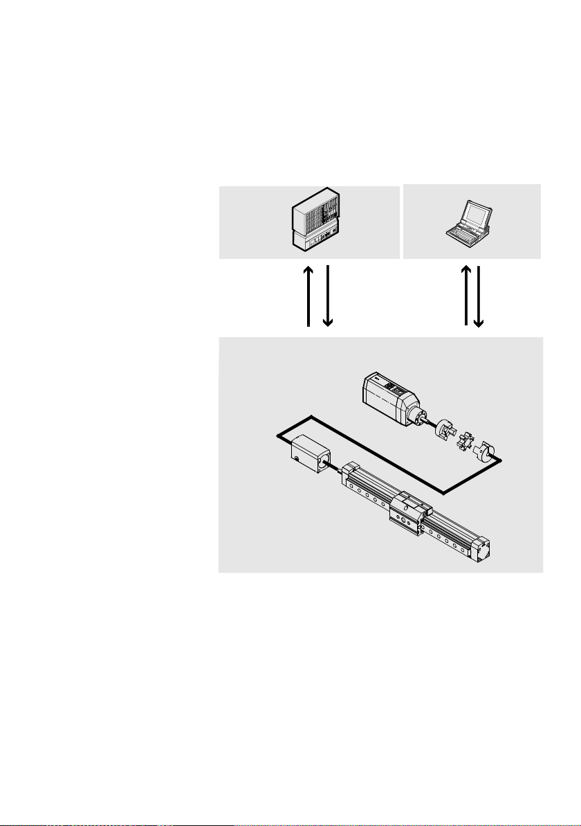
Sequence control
1
and parameter
access by the
higher-order
controller/field
bus master
2
Software level:
Commissioning
with the Festo
Configuration
Tool software
3
Drive level with
–Motorunit
– Coupling
– Coupling
housing
–Axis
12
I/O
CANopen
Profibus
DeviceNet
3
RS232
Fig. 1/1: Principle of a positioning system with the MTR-DCI
The motor unit type MTR-DCI-...-CO with CANopen fieldbus
interface permits positioning of the connected linear or rotation axis:
– corresponding to the device profile “CiA 402” from the
user organisation CIA.
– as per the “Festo Handling and Positioning Profile:”
Festo P.BE-MTR-DCI-CO-EN en 1209a
1-3
Page 26

1. System overview
You can parametrize and commission the MTR-DCI as follows:
– with th e FCT software package via the RS232 interface of
your PC
– with th e optional control panel with display and 4 operat-
ing buttons (only MTR-DCI-...-H2)
– via the field bus.
Functions
Parametrizing – Selecting the axis type and the axis para-
Position records – Compiling a position set table with set
Commissioning – Reference run (homing)
Diagnostics/
Service
meters
– Specifying a gear factor (with external
gears)
– Uploading/downloading configuration
data
– Saving different configurations in projects
number, target position, positioning
mode, positioning speed, acceleration
–Jogmode
– Teaching positions
– Moving in individual steps
– Starting and stopping positioning
procedures while commission ing
– Extended test functions e.g. status
displays
– Testing or demonstrating the position
records
– Reading and displaying diagnostic data x x x
HMI FCT Field bus
x
–
–
–
x x x
x
x
x
–
x
(x)
x
x
x
x
x
x
x
x
x
x
x
x
x
x
x
–
x
x
x
x
x
x
x
1-4
Festo P.BE-MTR-DCI-CO-EN en 1209a
Page 27
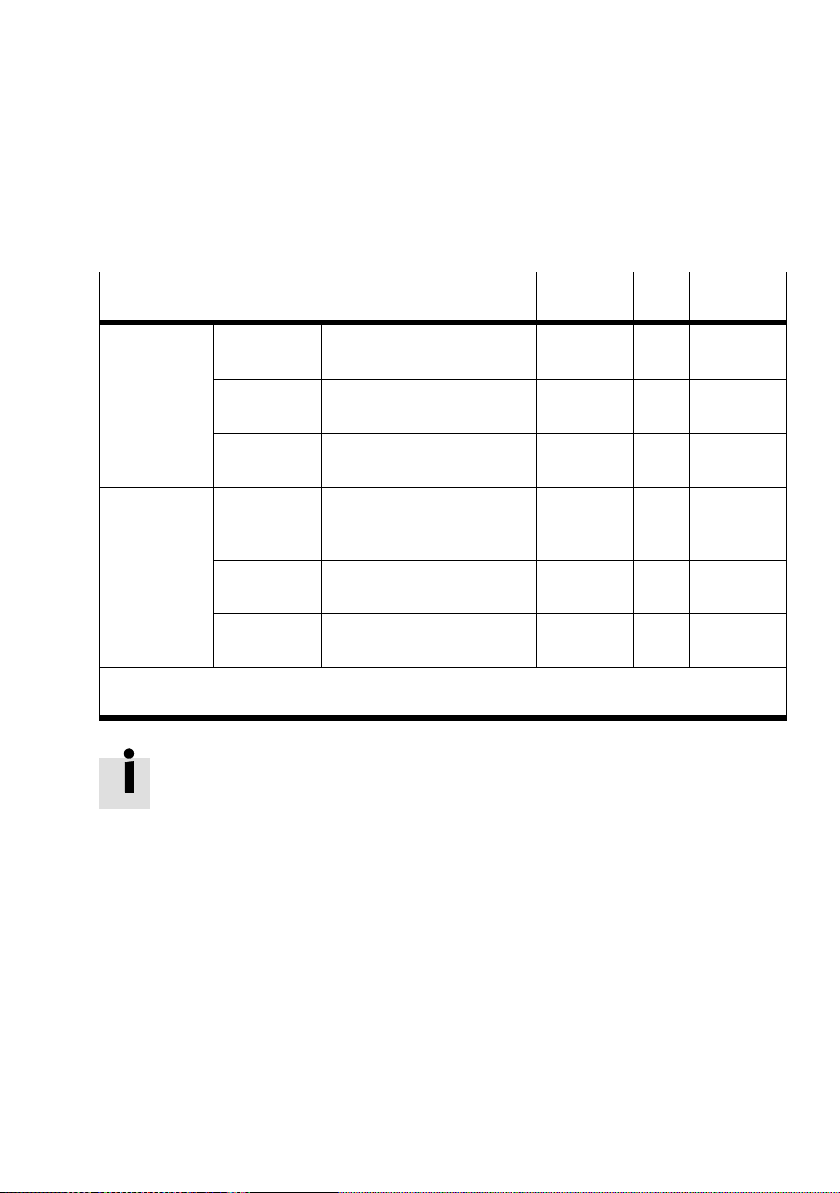
1. System overview
All parameters are entered or displayed in the relevant set
measuring units.
Measuring units
Linear axis
Rotation axis Degree Angle dimension
1)
Only with FCT when setting up a project
2)
Setting only with control panel [Settings] [Axis type] [Rotation axis]
Metric Metric measuring units,
e. g. mm, mm/s, mm/s
1)
Inches
Imperial measuring units,
e. g. inch, inch/s, inch/s
2
2
Increments Increment-based measuring
units, e. g. inc, inc/s, inc/s
360° = 1 revolution
e. g. deg, deg/s, deg/s
2
Revolutions2)Number of revolutions
e. g. rev, rev/min, rev/min
Increments Increment-based measuring
units, e. g. inc, inc/s, inc/s
2
2
2
Setting the units of measurement influences only the display.
All parameters are saved internally in the controller in increments (inc, inc/s, inc/s
2
they are written or read.
Dimensions transmitted by the RS232 or by the field bus refer
to an increment basis (conversion see appendix A.4)
Control
FCT Field bus
panel
x x –
– x –
– – x
x x –
x – –
– – x
...) and are not converted until
Festo P.BE-MTR-DCI-CO-EN en 1209a
1-5
Page 28

1. System overview
1.2 Field bus communication
1.2.1 Data exchange in CANopen
CANopen devices have an object directory which makes all
important slave parameters accessible in a standardized
manner. A CANopen system is essentially configured by
accessing the objects in the object directory of the individual
stations. The data exchange in CANopen is in the form of telegrams with which the work data is transmitted. A distinction
is made between Service Data Objects (SDO), which are used
for transmitting service data from and to the object directory,
and between Process Data Objects (PDO), which serve for the
fast transfer of current process states. In addition, telegrams
are defined for the network management and the fault messages.
SDO With SDOs you can access all entries in the Object Directory.
The relevant Object Directory entries can be addressed with
the index and subindex of the entry. SD Os are used mainly for
transmitting acyclic data, e. g. for initializing during the boot
procedure. Within an SDO only one object can be accessed. A
reply is always sent to an SDO: A pair of CAN telegrams per
object are transmitted.
PDO PDOs are in principle a grouping of objects (variables or para-
meters) from the Object Directory. Maximum 8 bytes from
different objects can be sent together in a PDO, i. e. the objects are mapped in the PDO. Process Data Objects can be
transmitted event-controlled, synchronous to a system pulse
sequence or on demand. PDOs are transmitted by simple
CAN messages and are suitable for transmitting cyclic data.
1-6
Festo P.BE-MTR-DCI-CO-EN en 1209a
Page 29

1. System overview
1.2.2 Data profiles FHPP and CiA 402
Festo has developed an optimised data profile, the “Festo
Handling and Positioning Profile (FHPP)” tailored to handling
and positioning tasks.
For drives with a CANopen interface, the CANopen profile
CiA 402 for control by the maste r can also be used as an alternative to the Festo profile. The CiA 402 profile is then also
the internally implemented profile; the FHPP interface is
mapped by an implementation of CiA 402. The communications profile is in both cases DS 301.
Data profile
FHPP Controller
CiA 402 Controller
Description
Control is efected via the cyclic 8-byte control and status data,
see sections 5.5.2 and 5.5.3
Parametrizing
Parametrizing is carried out:
– via a further 8 I/O bytes (Festo Parameter Channel FPC)
– optionally via releant SDO accesses.
For detailed information on the implemented objects see
appendix B.1.1.
Control is effected as per device profile CiA 402 with the following
deviations:
– “Positioning profile” subprofile
– Status transfer 19 and 20, see section C.2.
– Quick Stop active, status transition 12, see section C.2.
Parameterisation
Parameterisation is effected via SDO accesses (
For detailed information on the implemented objects see appendix C.1.
Tab. 1/1: Control and parametrizing methods depending on data profile
The FHPP enables uniform control and programming for the
various field bus systems and controllers from Festo. Parameter values, control and status bytes required during operation can be written and read via the Object Directory and a
structure description. Communication via the CANopen field
bus is made via 8 bytes of I/O data.
CiA
402).
Festo P.BE-MTR-DCI-CO-EN en 1209a
1-7
Page 30

1. System overview
The FHPP defines uniform operating modes and I/O data
structures for the user.
– Parameter access as per FHPP F PC (PDO 2; optional:
SDO)
– Sequence control as per FHPP Standard (PDO 1) with the
operating modes Direct mode or Record Select.
Direct mode Positioning tasks in positioning or power operation can be
executed as direct mode. The positioning task is transferred
directly in the I/O telegram (FHPP standard). The most important nominal values (position, velocity, force/torque...)
are thereby transferred. Supplementary parameters are determined via the parametrizing (FHPP FPC) .
Record Select Positioning tasks in positioning mode can be executed with
Record Select. The positioning data are set indirectly via positioning sets which are taught via FCT, the control panel or
field bus and saved in the controller. 31 position sets can be
saved in the MTR-DCI. A record contains all the parameters
which are specified for a positioning task. The record number
is transferred to the cyclic I/O data as the nominal or actual
value (FHPP standard).
1-8
DetailedinformationontheFHPPcanbefoundin
chapter 5.5.
Festo P.BE-MTR-DCI-CO-EN en 1209a
Page 31
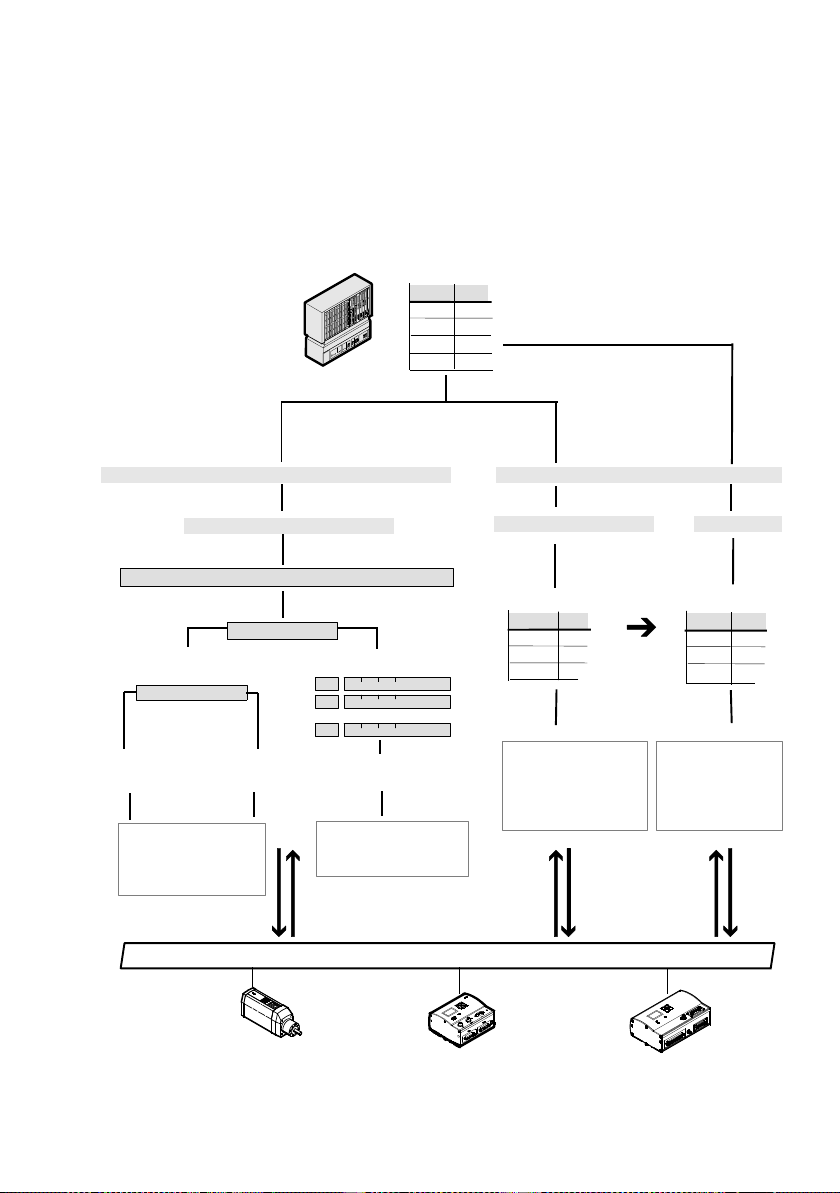
1. System overview
Festo Handling and Positioning Profile (FHPP)
...-FHPP.EDS
Object
SI
1000h
...
2...
3...
cyclic data channel
acyclic data channel (optional)
Sequence control
PDO 1 (FHPP standard)
CPOS* (reference travel, teach, start...)
CCON.B6/B7*
Direct mode
CDIR.B1/B2*
Positioning
mode
— *Control/status bytes
— Nominal/actual value
1, 2...
—....
Power
operation
TxPDO 1 RxPDO 1
8 bytes I/O as per FHPP standard
Record Select
1
2
...
n
Positioning
mode
— *Control/status bytes
— Record no.
—....
Parameter access
PDO 2 (FHPP-FPC)
PNU
hex
SI
PNU
100
...
1043
—....
— Parameter no. PNU
— Subindex SI
— Parameter value
—....
TxPDO 2 RxPDO 2
8 bytes I/O as per FHPP FPC
+ 2000h
Object
2064
2413
—....
— Object (Index)
— Subindex SI
— Parameter value
—....
TxSDO RxSDO
SD0
SI
h
...
h
Fig. 1/2: Festo Handling und Positioning Profile (FHPP)
Festo P.BE-MTR-DCI-CO-EN en 1209a
1-9
Page 32

1. System overview
1.3 Components
For setting up an electric drive with the MTR-DCI you will
require the following components:
Servo-motor unit MTR-DCI Motor with controller, available in four sizes, optionally with
control panel (type ...-H2).
By means of different gear reductions, different requirements can be fulffilled in respect of (gear) drive torque) and
(gear) drive speed (see appendix A.1). High drive output
torques with low drive output speeds are characteristic for
positioning functions. With the smaller gear reduction, the
positioning speed of the axis can be increased with correspondingly reduced positioning force.
Axis Linear or rotation axes as per catalogue
Coupling with coupling
housing
Power supply cable Power supply to the MTR-DCI via a power supply unit. The
Programming cable Parameterisation of the MTR-DCI during commissioning with
Field bus cable Operating the MTR-DCI on a higher-order controller
Reference switch Sensor as per appendix A.2.
Accessories For positioning systems Festo offers special matching acces-
In order to fit Festo axes, e.g. type DMES-... or type D NCE-...,
couplings and coupling housings are available as accessories. The motor unit is connected to the axis by means of a
clamping connector in the coupling housing. Additional motor flanges are not therefore necessary. Further information
can be found in the operating instructions for the axis.
electronics (logic voltage) can also be supplied with power
separately from the load voltage (see section 3.3).
the FCT
(PLC/IPC).
sories (see Festo delivery program or catalogue).
1-10
Festo P.BE-MTR-DCI-CO-EN en 1209a
Page 33
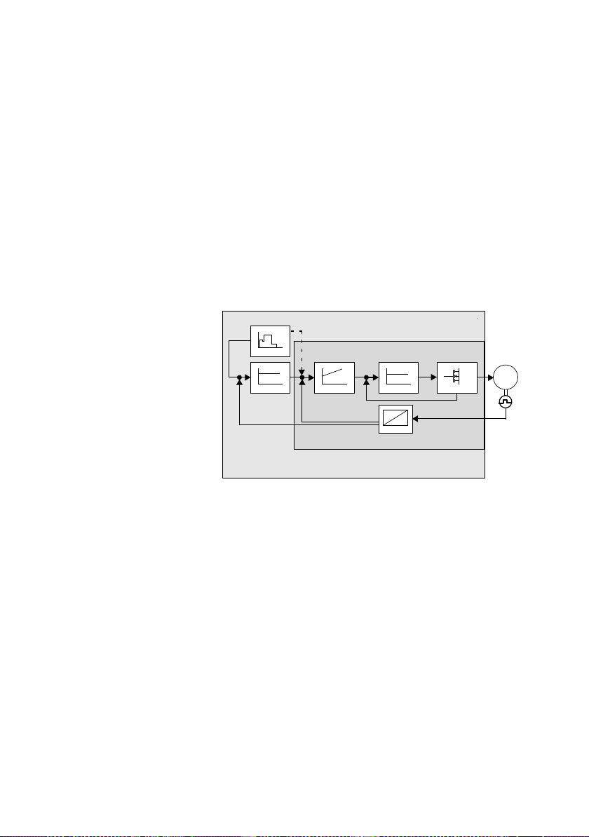
1. System overview
1.4 Control and regulating functions
The controller takes over the following tasks:
– Activation via FHPP or CiA 402,
– Specification of the nominal values
– Control of the following variables: position, speed,
acceleration, current.
1
Motor controller
2
Regulator
3
Nominal
value generator
4
Position
controller
5
Speed regulator
6
Current regulator
3
P
4
2
1
567
PI
P
8
M
7
Output stage
8
Signal converter
Fig. 1/3: Simplified diagram of the cascade regulator
Profile Position Mode Positioning mode
Operating mode for processing a positioning record or a direct positioning task with position control (closed loop position control)
The target position defines the position to which the drive
controller is to run. The target position is interpreted either
as an absolute or relative specification. The set target position is transferred to the nominal value generator. This generates a nominal position value for the position controller. For
position control, the current settings for speed, acceleration,
braking deceleration, etc. are taken into account.
Festo P.BE-MTR-DCI-CO-EN en 1209a
1-11
Page 34

1. System overview
Changes in position are recognized by the internal incremental sensor (optical encoder). With a known sta rting point
the actual position is calculated from the gear reduction
and/or the spindle slope.
Profile Torque Mode Power operation
Operating mode for executing a direct positioning task with
power operation (open loop transmission control) with motor
current regulation
nominal torque value (relative to the rated motor current)
to be specified to the controller. Power control takes place
indirectly via the regulation of the motor current. All specifications on forces/torques refer to the rated motor torque or
current.
Homing mode Reference travel
Execution of a positioning procedure in which the reference
point and therefore the source of the measuring reference
system of the axis are defined, e.g. via a reference switch
within the possible positioning path or with overcurrent
evaluation n the case of movement to a stop.
.
This operating mode enables an external
1-12
For commissioning, for testing or for demonstration the following functions are also available via the control panel of
the MTR-DCI-...H2:
– Positioning travel for defining the target position of a pos-
itioning record (Teach Mode), [Settings] [Position set]
– Positioning travel for testing all positioning records in the
positioning record table, [Demo posit tab]
– Positioning travel for testing a certain positioning record
in the positioning record table [Move posit set].
Festo P.BE-MTR-DCI-CO-EN en 1209a
Page 35

1. System overview
1.5 Operational safety
An extensive system of sensors and monitoring functions
ensures operational safety:
2
t-monitoring
–i
– Temperature monitoring (measuring the motor tempera-
ture and the power end stage temperature)
– Current monitoring
– Voltage monitoring
– Recognizing faults in the internal voltage supply.
– MTR-DCI-62...: Recognition of overvoltages in the in-
termediate circuit; brake chopper integrated.
– Drag error monitoring
Festo P.BE-MTR-DCI-CO-EN en 1209a
– Software end position recognition
note the following:
•
By the arrangement of the limit switches and, if necessary, additionally by means of mechanical stops, make
sure that the axis always lies within the permitted positioning range.
•
To detect a bus failure (wire break, master shutdown, ...)
activate Node Guarding as necessary on the CANopen
master; see section 6.5.1.
1-13
Page 36

1. System overview
Warning
Check the measures which are necessary within the
framework of your EMERGENCY STOP circuit for switching
your machine/system into a safe state in the event of an
EMERGENCY STOP.
•
If an EMERGENCY STOP circuit is necessary for your
application, use additional, separate safety limit
switches (e. g. as normally closed limit switches wired in
series).
– Cancelling the ENABLE signal at the controller inter-
face
– Switch off the load voltage.
1-14
Festo P.BE-MTR-DCI-CO-EN en 1209a
Page 37

1. System overview
1.6 Measuring reference system
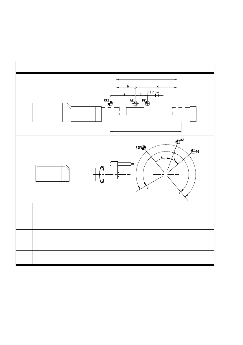
For commissioning, a measuring reference system for referencing the reference coordinates must be defined. By means
of the measuring system all (absolute) positions are defined
and movement can be made to them.
1.6.1 Reference points and positioning range
The measuring reference system is defined as follows:
1. Homing for defining the reference point
2. Setting the zero point (offset axis zero point and project
zero point)
3. Limiting the positioning range (software end positions).
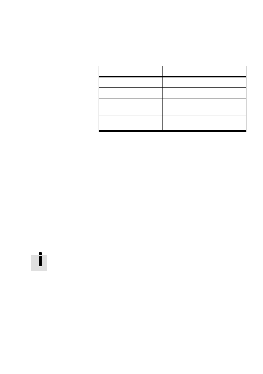
Reference point REF binds the measuring reference system to a reference switch
or a fixed stop, depending on the homing method. (see also
section “Homing reference travel”).
Axis zero point AZ is shifted by a defined distance to the reference point R EF
(offset of the axis zero point).
Project zero point PZ is a reference point within the effective stroke which the user
can select, and to which both the actual position and the
target positions in the position record table refer.
The project zero point is shifted by a defined distance to the
axis zero point AZ (offset of the project zero point). The
project zero point PZ can only be set via FCT or CAN/CI
object 21F4
/ FHHP 500 (not on the control panel).
h
Software end positions The permitted positioning range (work stroke) is limited by
the settings of the software end positions. The software end
positions refer to the axis zero point. If the target position of
a positioning command lies outside the software end positions, the positioning command will not be processed and an
error status will be set.
Festo P.BE-MTR-DCI-CO-EN en 1209a
1-15
Page 38
1. System overview
Measuring reference system
Linear axis with homing (referencing travel)
e
method: Fixed stop
f
Rotation axis with homing method:
Reference switch
REF
Reference point: Point ascertained during the reference run: reference switch or stop
AZ
Axis zero point: reference point for the project zero point and the software end positions.
PZ
Project zero point: Reference point for the actual position and absolute positions of the
positioning table.
a
Offset axis zero point: Distance of axis zero point AZ from reference point REF
b, c
Offset software end positions: limit the permitted positioning range (usable stroke).
d
Offset project zero point: distance from AZ
e
Effective stroke: Permitted positioning range
f
Rated stroke of the axis used
Tab. 1/2: Measuring reference system
1-16
Festo P.BE-MTR-DCI-CO-EN en 1209a
Page 39
1. System overview
Reference point Calculating specification
Axis zero point AZ =REF+ a
Project zero point PZ =AZ+ d =(REF+ a) + d
Lower software end
position
Upper software end
position
LSE =AZ+ b =(REF+ a) + b
USE =AZ+ c =(REF+ a) + c
Tab. 1/3: Calculating specifications for the measuring reference system with incremental
measuring systems
1.6.2 Signs and directions
All offsets and position values are vectors (with sign). Th e +/direction of the vectors can be assigned to the direction of
rotation of the motor shaft (view towards the motor shaft).
The factory setting is “+” for rotation in a clockwise direction;
“-” for rotation in an anti-clockwise direction. The assignment
can be reversed on the control panel (see chapter 4.5.2) or
via the FCT. Th is can be advantageous if you are using angled
or toothed belt drives. Afte reversal new homing (reference
travel) is then required.
The direction in which the work load moves depends on the
gear, the spindle type (left/right-hand turning), the sign for
the position specifications (+/-) and the work direction set.
Festo P.BE-MTR-DCI-CO-EN en 1209a
1-17
Page 40
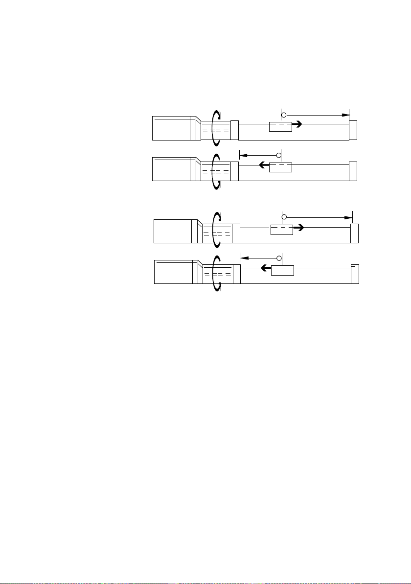
1. System overview
1
2
1
Factory setting of the work direction
+
—
—
+
1-18
2
Direction reversal by modifying the work direction
Fig. 1/4: Setting the work direction (example MTR-DCI +
DMES, axial gear, right-hand turning spindle)
Festo P.BE-MTR-DCI-CO-EN en 1209a
Page 41

1. System overview
1.6.3 Reference run (homing)
In the case of drives with incremental measuring system,
homing must always be carried out when the device is
switched on. This is defined drive-specifically with the parameter “Homing (reference travel) required” (PNU 1014,
CANopen/CI 23F6h).
The following homing modes are permitted:
– Search for stop in a negative direction
– Search for stop in a positive direction
– Search for reference switch in a positive direction
– Search for reference switch in a negative direction
(default).
In order to search for the reference point and for positioning
the drive in the axis zero point, you can set two different
speeds.
Festo P.BE-MTR-DCI-CO-EN en 1209a
Homing sequence:
1. Search for the reference point in accordance with the
configured method.
2. Move from reference point to axis zero point AZ (offset
axis zero point)
3. Setataxiszeropoint:
Current position = 0 – offset project zero point PZ.
After successful reference travel the drive stands at the axis
zero point AZ. On initial commissioning or following a change
of homing method the axis zero offset is = 0; after homing
the drive is then positioned at the reference point (REF).
1-19
Page 42
1. System overview
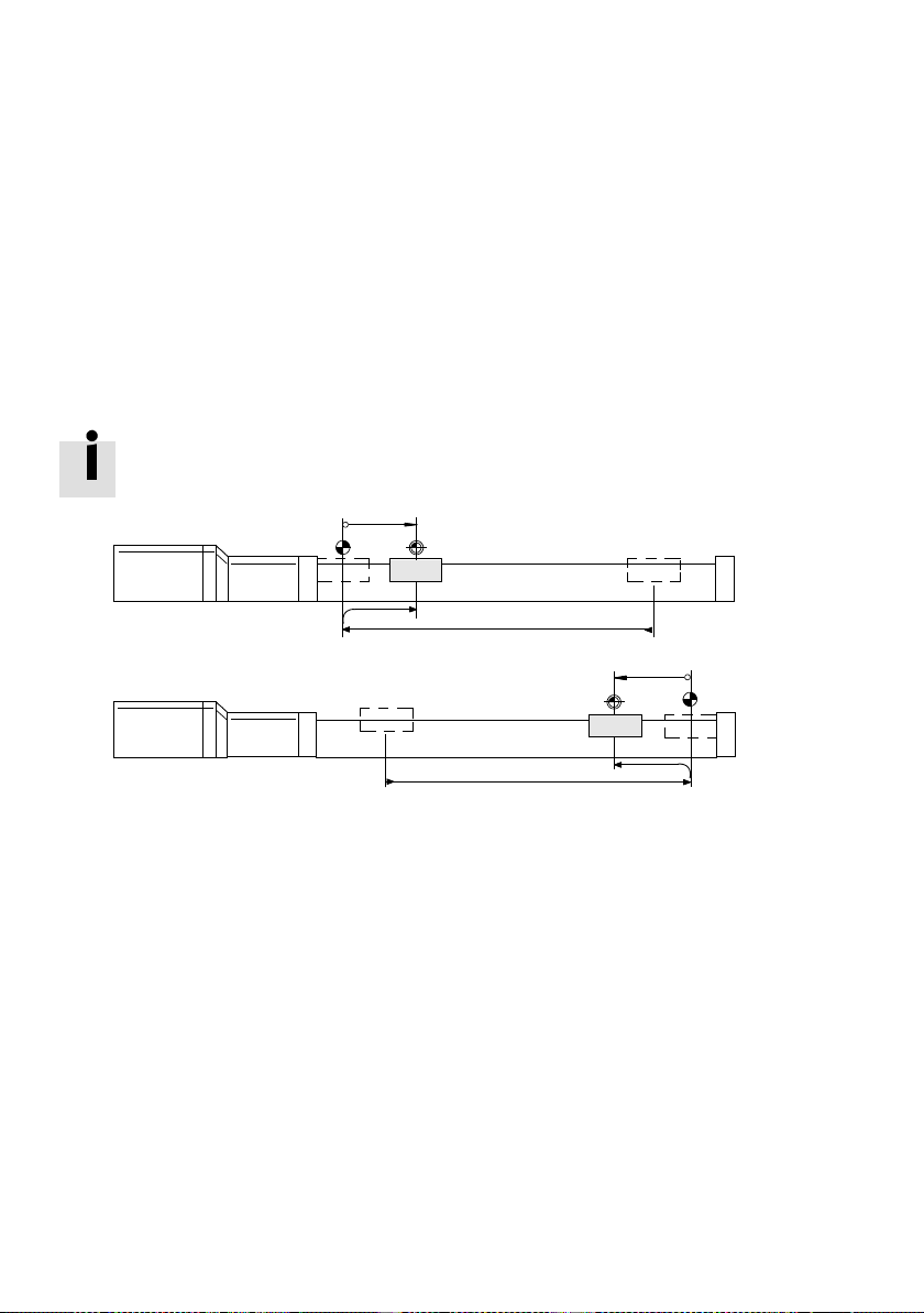
Search for fixed stop With this reference travel method, the drive moves at first at
search speed in a negative or positive direction until it
reachesthefixedstop.Ariseinthemotorcurrentsignalsthat
the stop has been reached. When the maximum motor current is reached at the same time as the motor is at a standstill, the MTR-DCI recognizes that the stop, and therefore the
reference position, has been reached.
As the axis must not stand still at the stop, the offset axis
zero point must ≠ 0 (min. 0.25 mm).
+
1
REF (-)
AZ
2
1
Stop in a negative direction
2
Stop in a positive direction
Fig. 1/5: Homing methods “Search for stop...”
—
AZ
REF (+)
1-20
Festo P.BE-MTR-DCI-CO-EN en 1209a
Page 43
1. System overview
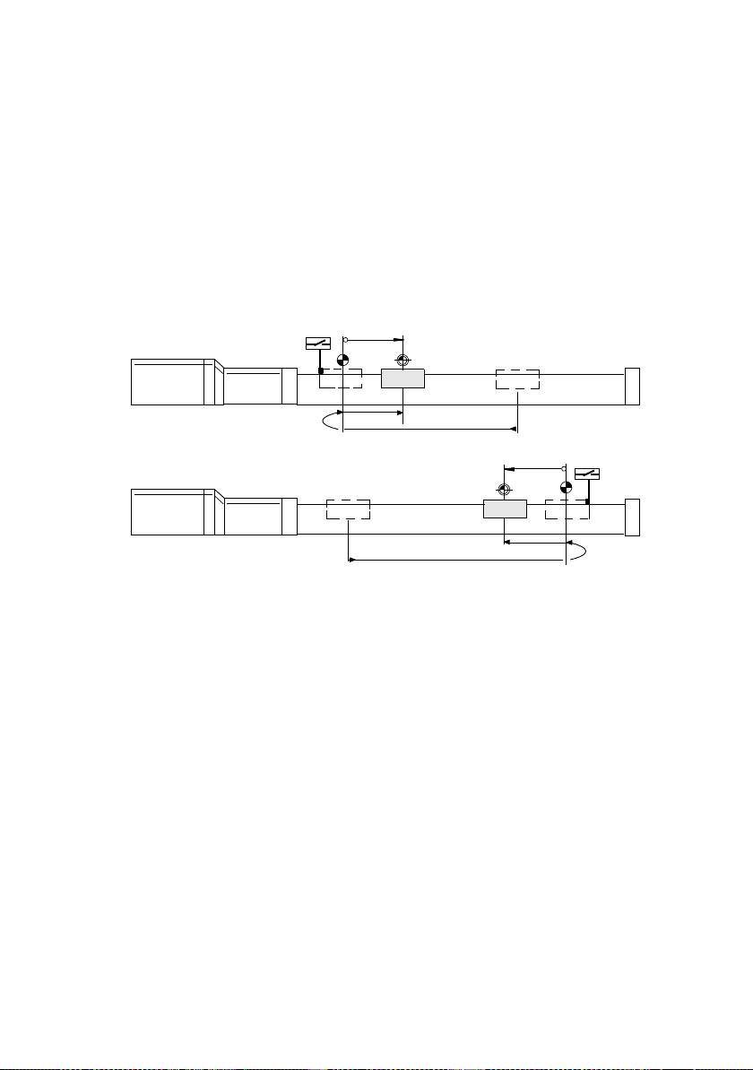
Search for reference switch In this reference travel method, the drive moves at first at
search speed in a negative or positive direction until it
reaches the limit switch. Then it moves back at creeping
speed: The reference position lies at the point at which the
reference switch becomes inactive again when the drive
moves back.
+
1
REF (-)
AZ
2
1
Reference switch in negative direction
2
Reference switch in positive direction
Fig. 1/6: Homing methods “Search for switch...”
If the drive stands on the reference switch at the start of
reference travel, it will move in the opposite direction to the
reference switch. The drive then m oves as usual to the axis
zero point.
—
AZ
REF (+)
Festo P.BE-MTR-DCI-CO-EN en 1209a
1-21
Page 44

1. System overview
1-22
Festo P.BE-MTR-DCI-CO-EN en 1209a
Page 45

Mounting
Chapter 2
Mounting
Festo P.BE-MTR-DCI-CO-EN en 1209a
2-1
Page 46

2. Mounting
Contents
2. Mounting 2-1.....................................................
2.1 General instructions 2-3.............................................
2.2 Dimensions of the motor unit 2-4.....................................
2.3 Fitting electric axes 2-5..............................................
2-2
Festo P.BE-MTR-DCI-CO-EN en 1209a
Page 47

2. Mounting
2.1 General instructions
Warning
Danger of electric shock, short circuits or unexpected
movements of the drive.
•
Always switch off the power supply before carrying out
fitting, installation and maintenance work.
Note
Handle all modules and components with great care. Note
especially the following:
– Screw connections must be fitted free of offset and
mechanical tension. Screws must be fitted accurately
(otherwise threads will be damaged).
– The specified torques must be observed.
– The modules must not be offset.
– Contact surfaces must be clean (avoid contact faults).
Festo P.BE-MTR-DCI-CO-EN en 1209a
2-3
Page 48
2. Mounting
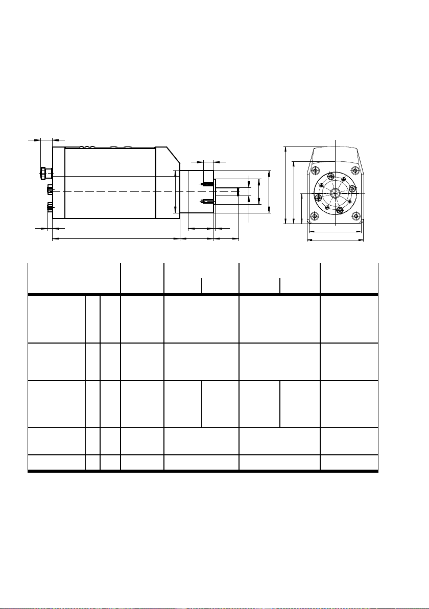
2.2 Dimensions of the motor unit
13
T1
D2
L5
5
L1
L4
L3
L2
H0
H2
D1
D3
D4
H1
B1
B2
Sizes [mm] 32 42 52 62
Gear ratio G7/G14 G7 G14 G7 G14 G7/G14/G22
Diameter of
flange/shaft
Height H H0
Length L L1
Width B B1B233.8 ±0.3
Depth T T1 6 M3: 7 / M4: 10 10 10
D D1
D2
D3
D4
H1
H2
L2
L3
L4
—
—
21.5 h8
6h7
65.3 ±0.4
21.6 ±0.15
41.5 ±0.3
175.5±1
—
18.7 ±0.6
2.5 ±0.3
46.3 ±0.4
42 g10
42 ±0.1
25 h8
8h7
70.8 ±0.4
26.5 ±0.6
54.5 ±0.4
176 ±1
33.3 ±1
25 ±1
2±0.2
44.8 ±0.4
53.3 ±0.4
176 ±1
46.3 ±1
25 ±1
2±0.2
52 g10
52 ±0.1
32 h8
12 h7
94.8 ±0.4
37 ±0.9
76.5 ±0.4
194 ±1
39 ±1
33 ±1
3±0.3
63.8 ±0.4
69.5 ±0.4
194 ±1
53 ±1
33 ±1
3±0.3
62 g10
62 ±0.1
40 j7
14 h7
128 ±0.5
60.8 ±0.35
128 ±0.5
270 ±1
47 ±1
39 ±1
5±0.3
105.1 ±0.4
105.1 ±0.4
Tab. 2/1: Dimensions of the motor unit
2-4
Festo P.BE-MTR-DCI-CO-EN en 1209a
Page 49

2. Mounting
2.3 Fitting electric axes
When fitting electric axes refer to the documentation for the
axes and accessory components used.
Make sure that:
Warning
If an axis is fitted in a sloping or vertical position, the work
load may fall down and injure somebody.
•
Use the motor unit preferably with self-locking or self-
braking spindle drives. You can then prevent the work-
ing load sliding down suddenly if there is a power fail-
ure.
•
With DMES-...: Check whether additional external safety
measures against spindle nut fracture are necessary
(e. g. toothed latches or moving bolts).
Festo P.BE-MTR-DCI-CO-EN en 1209a
•
the drive is fitted securely and is correctly aligned
•
the work space, in which the axis and work load move,
is of sufficient size for operation with a work load,
•
the work load does not collide with any component of the
drive when the slide moves into the end position.
•
Make sure that you observe the maximum permitted
values of the following variables: the basis point for forces
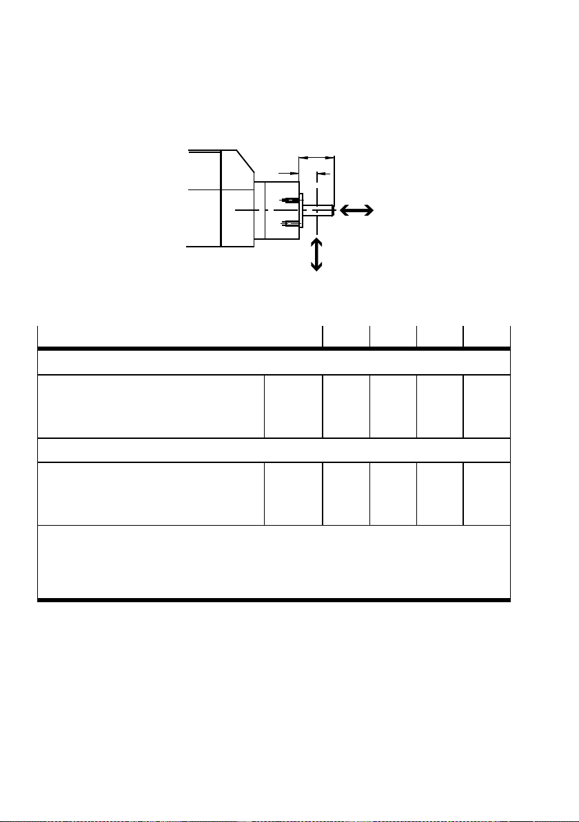
and torques is the centre of the shaft (L3 see Tab. 2/1).
2-5
Page 50
2. Mounting
L3
Fig. 2/1: Forces and torques
L3 x 0.5
F
y
F
x
Forces and torques
32 42 52 62
MTR-DCI-...-G7 1-stage
– Radial shaft load
– A xial shaft load
– Maximum permitted shaft output torque of
the gear
1)
Fy[N]
F
[N]
x
Mx [Nm]
40
10
0,4
160
50
0,8
200
60
2,0
MTR-DCI-...-G14/G22 2-stage
– Radial shaft load
– A xial shaft load
– Maximum permitted shaft output torque of
the gear
1)
With operating factor cb=1.0 (3 hours operation daily, no shocks, direction of rotation constant).
1)
Fy[N]
F
[N]
x
M
[Nm]
x
70
20
1,0
230
80
7,5
320
100
12,0
The gear output torque of the motor unit is usually much lower, see Technical specifications,
Appendix A, Mechanical specifications.
2)
MTR-DCI-62...-G22: in the start-up phase speed torque peaks up to 37 Nm are possible at 20 A
peak current.
Tab. 2/2: Permitted loading of the gear shaft
240
50
4
360
70
25
2)
2-6
Festo P.BE-MTR-DCI-CO-EN en 1209a
Page 51
2. Mounting
Note
Motor unit MTR-DCI-62-...-G22 can generate up to 37 Nm
at a peak current of 20 A in the start-up phase.
•
Make sure by calculating the dynamic loading that
the maximum permitted shaft output torque of the gear
is not exceeded in the start-up phase (e.g. by reducing
the load).
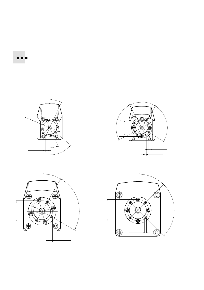
Use the thread on the front of the gear (see Fig. 2/2) for fitting the MTR-DCI to a mechanical drive device (machine
frame).
•
In order to minimize the shaft offset: Position the axis with
the aid of the centring diameter (D1 or D3 see Tab. 2/1)
relative to the rotary axis of the mechanism to be driven.
•
Fasten the motor unit with 4 screws and tighten the
4 screws with the specified tightening torque.
Festo P.BE-MTR-DCI-CO-EN en 1209a
The motor unit MTR-DCI-32 has a total of 6 threads for different motor mounting variants (axial, parallel). In each case
only 4 screws must be used.
Size
MTR-DCI-32-... M3 6mm 1.2 Nm
MTR-DCI-42-... M3 7mm 1.2 Nm
MTR-DCI-52-... M5 10 mm 5.9 Nm
MTR-DCI-62-... M5 10 mm 5.9 Nm
Thread depth Tightening torque
M4 10 mm 2.9 Nm
Tab. 2/3: Tightening torques
2-7
Page 52
2. Mounting
In order to fit Festo axes, e. g. type DMES-... or DNCE-...,
couplings and coupling housings are available as accessories.
The motor unit is connected to the axis by means of a clamp
in the coupling housing. Additional motor flanges are not
therefore necessary. Further information can be found in
appendix A.2 and in the operating instructions for the axis.
MTR-DCI-32-...
25°
dia. 32
4x 90°
M3 x6 (6)
25°
50°
MTR-DCI-52...
30°
4x 90°
dia. 40
M 5 x10(4x)
dia. 50
MTR-DCI-42-...
dia. 32
dia. 36
MTR-DCI-62...
M 5 x10(4X)
28°
32°
4x 90°
M 4 x10(4x)
M 3 x7(4x)
45°
4X 90°
Fig. 2/2: Fastening the drive by means of the front threads (direct fastening)
2-8
Festo P.BE-MTR-DCI-CO-EN en 1209a
Page 53

Installation
Chapter 3
Installation
Festo P.BE-MTR-DCI-CO-EN en 1209a
3-1
Page 54

3. Installation
Contents
3. Installation 3-1...................................................
3.1 Overview of installation 3-3..........................................
3.2 Earthing 3-6.......................................................
3.3 Power supply 3-7..................................................
3.3.1 Requirements of the power supply 3-7.........................
3.3.2 Load and logic voltages 3-8...................................
3.4 Serial interface 3-11.................................................
3.5 Input for external reference switch 3-13.................................
3.6 Controller 3-15.....................................................
3.7 Connecting the field bus 3-18.........................................
3.7.1 Field bus cable 3-18..........................................
3.7.2 Fieldbus bit rate and fieldbus length 3-19........................
3.7.3 Bus termination with terminating resistors 3-20...................
3-2
Festo P.BE-MTR-DCI-CO-EN en 1209a
Page 55
3. Installation
3.1 Overview of installation
Warning
Danger of electric shock, short circuits or unexpected
movements of the drive.
•
Always switch off the power supply before carrying out
fitting, installation and maintenance work.
Caution
Incorrectly pre-assembled cables may damage the electronic components and trigger unexpected movements of
the motor.
•
For connecting the electric components of the system,
use only the cables listed as accessories (see Tab. 3/2).
Only in this way can you be sure that the system will
work properly.
Festo P.BE-MTR-DCI-CO-EN en 1209a
Note
•
Lay all moveable motor and sensor cables free of bends
and free of mechanical stress, if necessary, in a drag
chain.
3-3
Page 56
3. Installation
1
Serial
interface
2
Connection for
the reference
switch
3
CANopen field
bus (I/F)
4
Power supply
1
2
3
(Power)
4
Fig. 3/1: Connections on the MTR-DCI
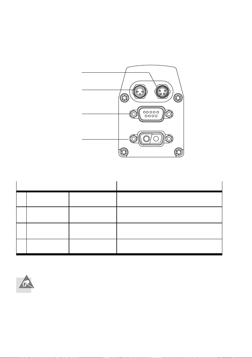
ConnectionontheMTR-DCI
1 Serial interface – M8x1, 4-pin
–Socket
2 Reference switch – M8x1, 3-pin
–Socket
3 CANopen field bus – Sub-D, 9-pin
–Plug
4 Power supply – Sub-D, 2-pin
–Plug
Tab. 3/1: Description of the connections
If non-assigned plug connectors are touched, there is a
danger that damage may occur to the MTR-DCI or to other
parts of the system as a result of ESD (electrostatic discharge). Place protective caps on unused terminals in order
to prevent such discharges.
3-4
Description
RS232 interface for parameterizing, commissioning and diagnosing with FCT
Sensor input for switch type normally open
contact in th e design PNP
Interface for connection to CANopen field bus
Connection with 2 high-current contacts
Festo P.BE-MTR-DCI-CO-EN en 1209a
Page 57
3. Installation
The plug connectors on the Festo cables listed in the following are designed to conform to protection class IP54 when
connectors are plugged in and secured, or when the connections on the MTR-DCI are equipped with protective caps.
Caution
Long lines reduce immunity to interference (EMC).
•
Observe the specified maximum cable lengths.
Connection
Serial interface Programming cable KDI-MC-M8-SUB-9-2,5 2.5 (max. 2.5)
Reference switch Connecting cable KM8-M8-GSGD-... 0.5/1/2/5
Voltage supply Power supply cable KPWR-MC-1-S UB-9HC-... 2.5/5/10
Power supply Supply cable KPWR-MC-1-SUB-9HC-... 2.5/5/10
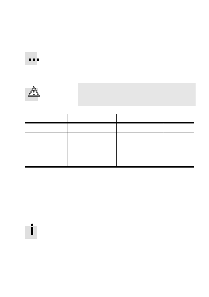
Cable Designation Length [m]
(max. 10)
(max. 10)
Tab. 3/2: Overview of cables (accessories)
Complying with the IP protection class
•
Seal unused M8 connections with ISK-M8 protective caps
(accessories),
•
Tighten the union nuts/locking screws on the plugs by
hand.
Observe the permissible torques specified in the documentation for the cables and connectors used.
Festo P.BE-MTR-DCI-CO-EN en 1209a
3-5
Page 58

3. Installation
3.2 Earthing
Note
•
Connect the earth connection of the MTR-DCI with low
impedance (short cable with large cross-sectional area)
to the earth potential.
This prevents interference from electromagnetic sources
and ensures electromagnetic compatibility in accordance
with EMC directives.
In order to connect the MTR-DCI to the earth potential, use
only the following earth connection:
– Earthing strap on the free end of the power supply cable,
see assembly instructions for cable KPWRMC-1-SUB-9HC-... (See chapter 3.3.2)
Caution
Earth or ground loops can make EMC safety measures
ineffective and allow high compensating currents to destroy the motor unit.
•
Connect only the cable screen of the power supply cable
to the functional earth FE.
•
The GND connection must not be made to the housing,
screening or functional earth FE!
•
Never connect one of the voltage connections (see
chapter 3.2, A1, A2) to FE or the housing.
This will avoid damaging the device and impairing protection against electromagnetic interference (EMC).
3-6
Festo P.BE-MTR-DCI-CO-EN en 1209a
Page 59
3. Installation
3.3 Power supply
3.3.1 Requirements of the power supply
Warning
•
In order to provide the electric power supply, use only
PELV circuits as per IEC/DIN EN 60204-1 (Protective
Extra-Low Voltage, PELV).
Take into account also the general requirements for
PELV circuits as per IEC/DIN EN 60204-1.
•
Use only power sourcers which guarantee reliable
electrical isolation of the operating voltage as per
IEC/DIN EN 60204-1.
By the use of PELV power units, protection against electric
shock (protection against direct and indirect contact) is guaranteed in accordance with IEC/DIN EN 60204-1 (electrical
equipment of machines, general requirements).
Festo P.BE-MTR-DCI-CO-EN en 1209a
Caution
Damage to the device caused by overvoltage
The voltage inputs of the motor unit have no internal
protection against overvoltage.
•
Make sure that the permitted voltage tolerance is
not exceeded. The tolerance must also be observed
directly at the voltage connections of the MTR-DCI
(see appendix A.1).
•
Install external fuses (see Tab. 3/4).
3-7
Page 60
3. Installation
3.3.2 Load and logic voltages
Load voltage The power electronics and the motor are supplied with direct
current via the voltage connection.
•
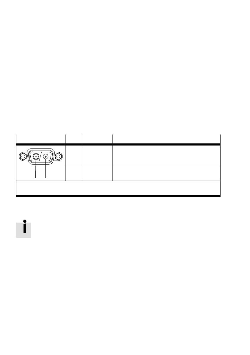
Use the power supply cable KPWR-MC-1-SUB-9HC-... (max
length of 10 m).
•
Use a closed-loop controlled power unit with high output
reserve and external fuse for the load voltage supply.
Plug
A1
1)
Cable colours with power supply cable KPWR-MC-1-SUB-9HC-...
2)
Do not connect GND with the housing, screening or functional earth (FE)!
A2
Pin Colour
A1 black (1) MTR-DCI-32/42/52:
A2 black (2) MTR-DCI-32/42/52/62: POWER GND
1)
Description
MTR-DCI-62:
Tab. 3/3: Connecting the power supply to the motor unit
Closed-loop controlled DC motors have a much higher current
consumption during the switch-on or starting torque than in
rated operation. These consumers cause a brief overloading
of the power supply or a short circuit.
Power supply units with U/I output curve continue to provide
the full output current (at reduced output voltage) even in the
event of a higher load or short circuit.
With power units with additional output reserve (power
boost), the output voltage remains constant even during
overload. Power units with U/I characteristic curve and power
reserve are therefore optimally suited for universal industrial
use.
POWER +24 VDC
POWER +48 VDC
2)
3-8
Festo P.BE-MTR-DCI-CO-EN en 1209a
Page 61
3. Installation
Note the following selection criteria with the power supply of
the MTR-DCI:
– The power unit rated current should correspond at least
to the motor starting current (peak current).
– Motor tolerances with 20 % - 50 % output reserve should
be considered.
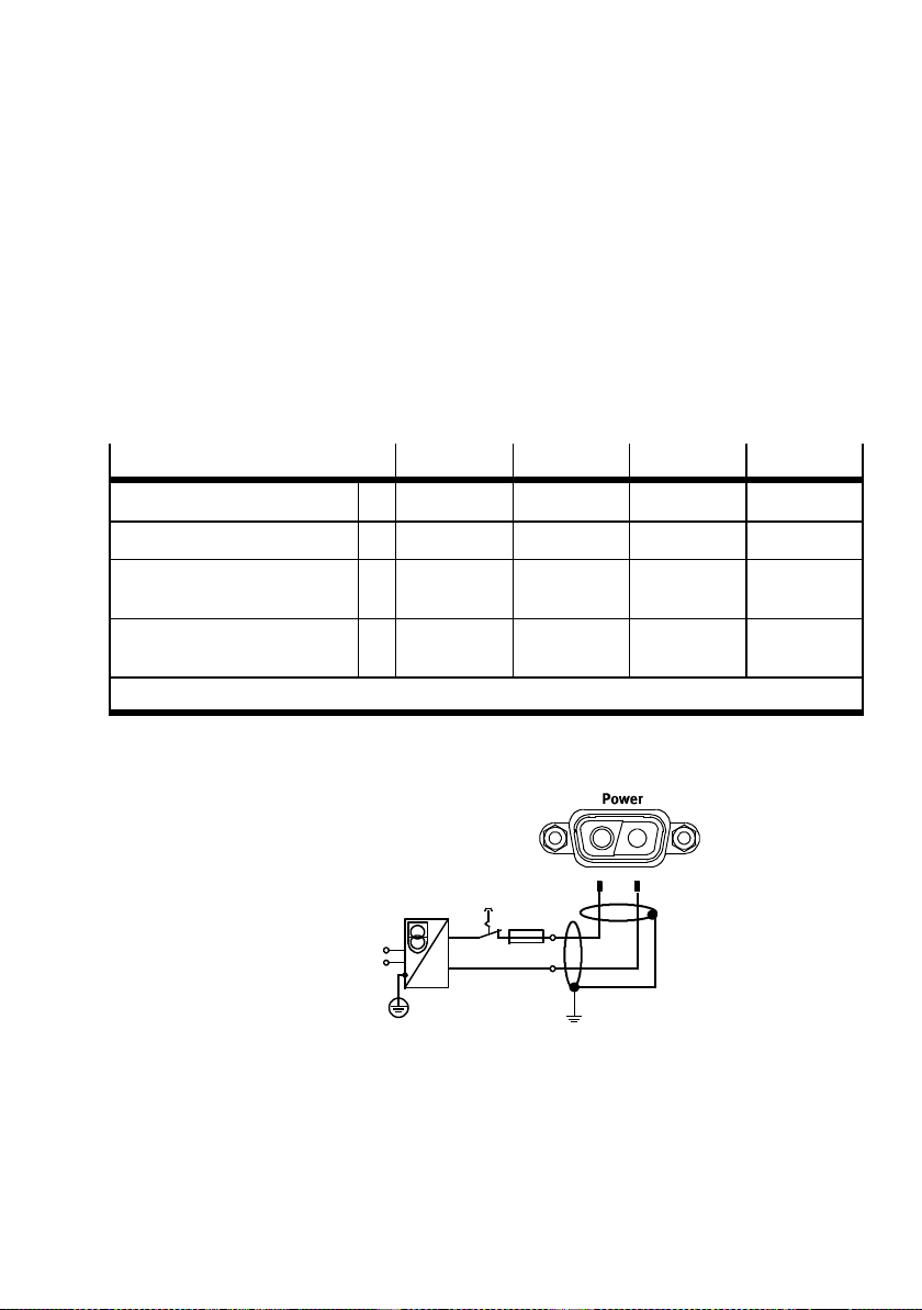
Voltage supply
Rated motor current A 0.73 2 5 6.19
Peak motor current A 2.1 3.8 7.7 20
Nominal current of power supply unit
External fuse (secondary side) A 5A
1)
Exception
MTR-…-32 MTR-…-42 MTR-…-52 MTR-…-62
A ≥3 ≥6 ≥10 ≥15
slow-blowing7Aslow-blowing
10 A
slow-blowing
Tab. 3/4: Requirement for power units and fuses
1
External fuse
2
Earth connection
(see chapter 3.2)
A1 A2
A1 A2
Fig. 3/2: Example of connection – Power supply
1)
25 A
slow-blowing
Festo P.BE-MTR-DCI-CO-EN en 1209a
3-9
Page 62

3. Installation
Logic voltage The logic voltage is supplied either together with the load
voltage via the power supply connection (internal) or separ-
ately from the load voltage (external) via the field bus
adapter FBA-... . The MTR-DCI-32 can only be supplied with
logic voltage via the field bus adapter.
Logic voltage supply
– via power supply — x x x
– via field bus adapter FBA-... x x x x
32 42 52 62
Tab. 3/5: Logic voltage supply
Logic voltage supply via field bus a dapter FBA-...
The load voltage is supplied via the power supply connection.
The logic voltage is supplied via the field bus adapter FBA-... .
Due to the separate power supply, the load voltage can be
switched off e.g. in the event of EMERGENCY STOP. Despite
this, the controller still functions and maintains its reference
position.
Information on the connection specifications of the field bus
adapter can be found in chapter 3.6. and in the assembly
instructions for the field busa adapter.
Switch-on sequence Do not switch on the logic voltage after the load voltage,
as the MTR-DCI may thereby be switched off and on again
(Reset).
Failure of logic voltage If there is a failure of the logic voltage, the controller will
switch itself off.
With MTR-DCI 42, 52, 62: If the load voltage is still applied,
the controller will switch itself on again, but is no longer
referenced.
3-10
Festo P.BE-MTR-DCI-CO-EN en 1209a
Page 63
3. Installation
3.4 Serial interface
Serial interface for parametrizing, commissioning and diagnosing
In order to connect a PC to the MTR-DCI, use exclusively the
following cable:
– Programming cable KDI-MC-M8-SUB-9-2,5
•
If necessary, remove the protective cap from the serial
interface of the MTR-DCI.
•
Connect the following terminals with the programming
cable:
– the connection socket on the MTR-DCI
– a serial interface COMx of the diagnostic PC.
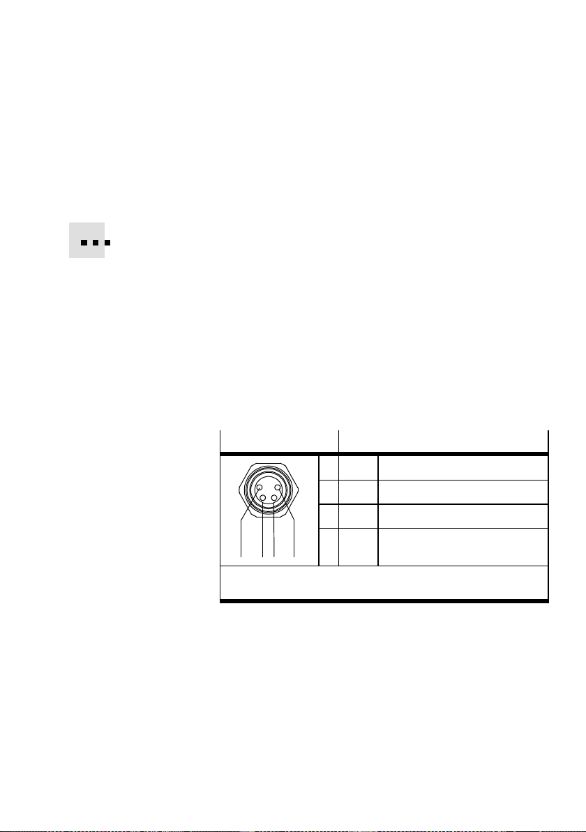
M8x1 socket Description
Festo P.BE-MTR-DCI-CO-EN en 1209a
1 GND Ground
2 TXD RS232 transmitting cable
3 RXD RS232 receiving cable
1243
4 --- reserved for servicing personnel –
1)
The levels correspond to the RS232 standard
Data transfer rate: 9600 bit/s
do not connect.
1)
Tab. 3/6: Pin assignment of the serial interface on the
MTR-DCI
1)
3-11
Page 64

3. Installation
Information on commissioning and parametrizing the
MTR-DCI via the serial interface can be found in chapter 5.3
and in the help system for the FCT software package.
Information on transmitting CI commands via the serial
interface can be found in the appendix C.3.2.
Note
The RS232 interface is not electrically isolated. It is not
suitable for permanent connection to PC systems, nor for
use as a control interface.
•
Use this terminal only for commissioning.
•
Remove the programming cable in continuous operation.
•
Seal the terminal with the protective cap supplied (ISKM8).
3-12
Festo P.BE-MTR-DCI-CO-EN en 1209a
Page 65
3. Installation
3.5 Input fo r external reference switch
If you are not using a reference switch:
•
Seal the terminal with the protective cap supplied
(ISK-M8).
Selecting the reference switch:
•
Usethecorrectswitchtype“normally-opencontact”in
the PNP variant for the reference switch.
•
Usea reference switch with screw locking (outer thread
M8x1) at the end of the cable or, as adapter, the connecting cable KM8-M8-... with screw locking.
Use e. g. the following proximity switches from Festo:
– Magnetic proximity switches SMT-8M-...
– Inductive proximity sensor SIEN-...-M8B-...
Festo P.BE-MTR-DCI-CO-EN en 1209a
•
When selecting the sensor, note that the accuracy of the
switchover point of the sensor determines the accuracy of
the reference point.
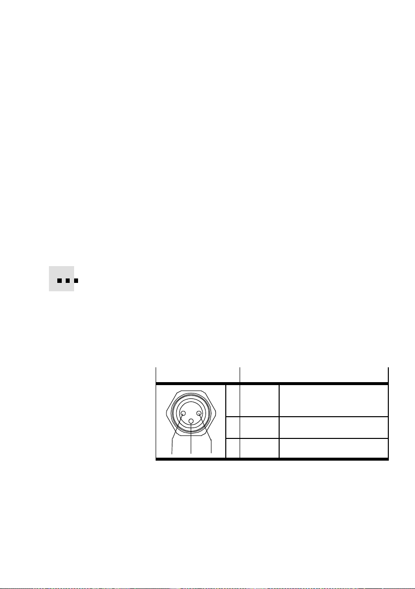
M8x1 socket
134
Description
1 DC +24 V DC +24 V voltage output
(only for reference switch)
4 REF Contact reference switch
3 GND Ground
Tab. 3/7: Connection REF (reference switch) on the MTR-DCI
The power supply for the reference switch (DC 24 V/Ground)
is provided via pin 1/3.
3-13
Page 66

3. Installation
Caution
Damage to the device.
The DC 24 V voltage at pin 1 does not have any special
protection against overload; the voltage is taken from the
main supply with protection against ESD and incorrect
polarity.
•
Use this connection only for the reference switch (sensor
supply).
Use of this connection as a power supply for other devices
is not permitted.
The input for sensor signal REF complies in its electrical
features with the input specification in the appendix
“Technical specifications”.
3-14
Festo P.BE-MTR-DCI-CO-EN en 1209a
Page 67
3. Installation
3.6 Controller
Communication with the higher-order controller is made via
the control connection on the MTR-DCI-...
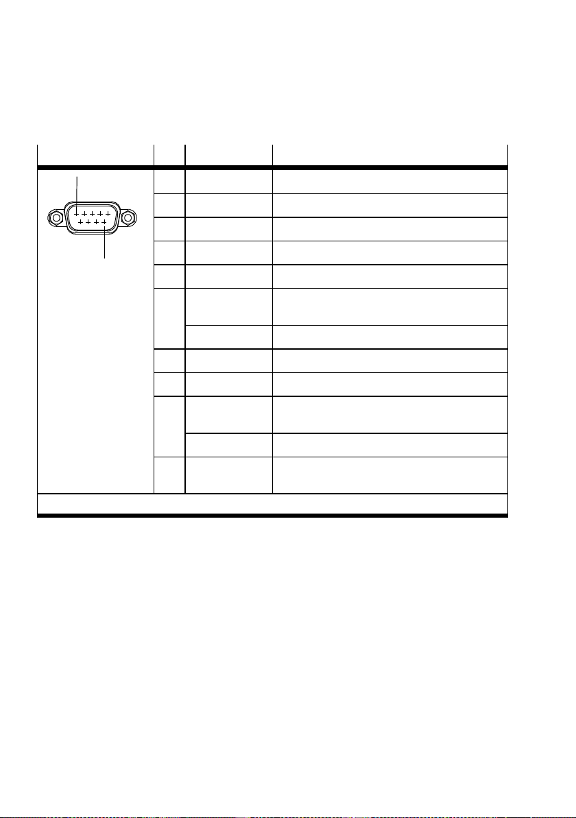
There is a 9-pin Sub-D plug on the MTR-DCI-...-CO for connecting the field bus. This connection serves for the incoming and
continuing field bus cables.
Note
Only the field bus plug FBA-CO-SUB-9-M12 from Festo
complies with IP 54.
Note
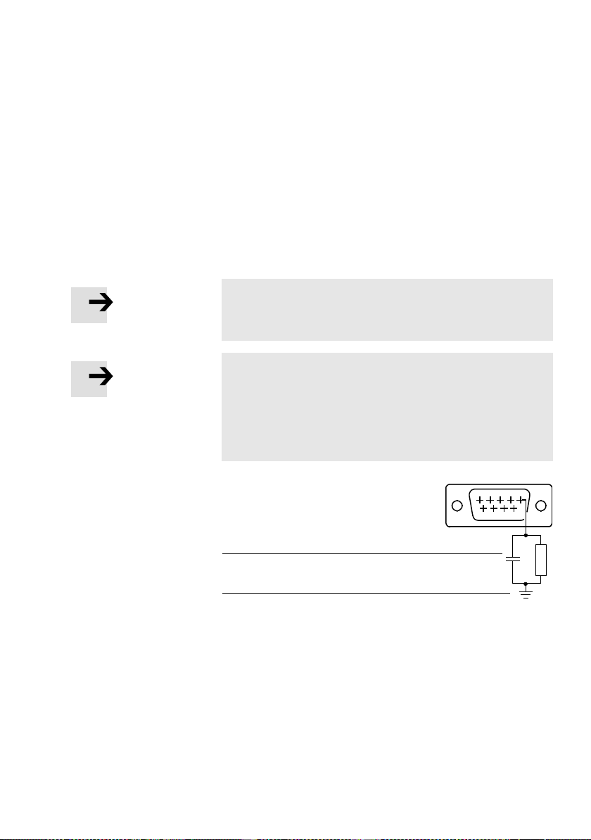
The screening connection at pin 5 of the fieldbus interface
is capacitively connected internally with high impedance to
the housing. This prevents compensating currents from
flowing via the screening of the fieldbus cable (see
Fig. 3/3).
1
Capacitive
connection
2
Housing
1
2
Fig. 3/3: Screening connection inside the MTR-DCI
Festo P.BE-MTR-DCI-CO-EN en 1209a
51
96
3-15
Page 68
3. Installation
Connection Pin Designation Function
1
9
1) internal or external supply of the bus interface see Tab. 3/9
1 n.c. not connected
2 CAN_L CAN Bus Low
3 CAN GND CAN bus reference potential
4 n.c. not connected
5 CAN_SHLD screening, capacitive connectionto housing
61)n.c. optional for MTR-DCI-42,52,62:
CAN_V- external supply GND
7 CAN_H CAN Bus High
8 n.c. not connected
91)n.c. optional for MTR-DCI-42,52,62:
CAN_V+ external supply 24 V
– Sc reening/
housing
not connected (= internal GND supply)
not connected (= internal 24 V supply)
connection to functional earth
Tab. 3/8: Connection “I/F” (controller connection) on the MTR-DCI-...-CO
3-16
Festo P.BE-MTR-DCI-CO-EN en 1209a
Page 69
3. Installation
Power supply to the bus interface 32 421)521)62
2)
Internal supply:
– Do not connect pins 6 and 9
– CAN bus (pins 2, 3, 7) potential refers to (load) voltage supply of
the MTR-DCI.
External power supply:
– Pins 6 and 9 must be supplied with 24 V (logic voltage)
– CAN bus (pins 2, 3, 7) potential refers to the bus voltage supply
(enables electrically isolated bus connection).
1)
Depends on parametrizing
– “CAN voltage supply (CAN power supply)” (see section 5.2.7) or
– [CAN volt.supply] on the control panel (see section 4.5, [CAN paramete r])
2)
default
— x
x
2)
x x x
2)
x
Tab. 3/9: Power supply for bus interface
Caution
Damage to other field bus devices
If you are using the external logic power supply via the
field bus adapter FBA-... (see chapter Accessories) there
will be a voltage of DC 24 V at pin 9.
•
Check whether there is any danger for other field bus
slaves.
•
Note the pin assignment in accordance with the assem-
bly instructions for the field bus adapter.
1)
2)
x
Festo P.BE-MTR-DCI-CO-EN en 1209a
3-17
Page 70

3. Installation
3.7 Connecting the field bus
3.7.1 Field bus cable
Note
Faulty installation and high transmission rates may cause
data transmission errors as a result of signal reflections
and attenuations.
Transmission errors can be caused by:
– missing or incorrect terminating resistor
– incorrect screened connection
–branches
– transmission over large distances
– inappropriate cables
Observe the cable specification! For information on the
cable type refer to the manual for your controller or to CIA
specification DS 102.
Note
If the MTR-DCI is fitted onto the moving part of a machine,
the field bus cable on the moving part must be provided
with strain relief. Please observe also the relevant regulations in EN 60204 part 1.
Use a twisted-pair, screened 4-wire cable as fieldbus cable.
If you are using the Festo field bus plug, a cable diameter of
5 ... 8 or 7 ... 10 mm is permitted.
Bus length Exact specifications on the bus length can be found in the
next section and in the manuals for your control system.
3-18
Festo P.BE-MTR-DCI-CO-EN en 1209a
Page 71
3. Installation
3.7.2 Fieldbus bit rate and fieldbus length
Note
The maximum permissible fieldbus segment lengths depend on the bit rate used. You will find detailed information in the manuals for your control system or bus interface, or in CiA specification DS 102.
•
Observe the maximum permissible segment length
(cable length without repeater) if you connect the MTR-
DCI to a fieldbus segment.
•
Avoid branch lines.
Note
•
Refer to the manuals for your control system or bus in-
terface in order to ascertain which T-adapter and maxim-
um branch line length are permitted for your controller.
Also take into account the sum of the branch line lengths
when calculating the maximum permitted length of the
fieldbus cable.
Festo P.BE-MTR-DCI-CO-EN en 1209a
Bit rate
1000 kbit (1 Mbit) 40 m
20 kbit 1000 m
Maximum segment length
Tab. 3/10: Maximum fieldbus segment lengths depending on
the bit rate
Notes on setting the bit rate and further bus parameters on
the control panel can be found in section 5.2.7.
3-19
Page 72

3. Installation
3.7.3 Bus termination with terminating resistors
Note
If the MTR-DCI is at the beginning or end of the field bus
segment, a bus termination will be required.
•
Always use a bus termination at both ends of the field
bus.
If the MTR-DCI is to be connected at the end of the fieldbus, a
terminating resistor (120Ω, 0.25W) must be installed in the
fieldbus socket:
•
Connect the terminating resistor between the cores for
CAN_H and CA N_L.
3-20
Festo P.BE-MTR-DCI-CO-EN en 1209a
Page 73

Control panel (only type MTR-DCI-...-H2)
Chapter 4
Control panel (only type MTR-DCI-...-H2)
Festo P.BE-MTR-DCI-CO-EN en 1209a
4-1
Page 74

4. Control panel (only type MTR-DCI-...-H2)
Contents
4. Control panel (only type MTR-DCI-...-H2) 4-1...........................
4.1 Composition and function of the control panel 4-4.......................
4.2 The menu system 4-6...............................................
4.2.1 Accessing the main menu 4-6.................................
4.2.2 Selecting a menu command 4-6...............................
4.3 [Diagnostic] menu 4-8..............................................
4.4 [Positioning] menu 4-11..............................................
4.4.1 [Positioning] [Move position set] 4-12...........................
4.4.2 [Positioning] [Demo position table] 4-13.........................
4.4.3 [Positioning] [Homing] 4-14....................................
4.5 Menu [Settings] 4-16................................................
4.5.1 [Settings] [Axis type] 4-17.....................................
4.5.2 [Settings] [Axis parameter] 4-18................................
4.5.3 [Settings] [Homing paramet.] 4-19..............................
4.5.4 [Settings] [Position set] 4-20...................................
4.5.5 [Settings] [Password edit] 4-21.................................
4.5.6 [Settings] [CAN parameters] 4-23...............................
4.6 Menu command [HMI control] 4-25.....................................
4-2
Festo P.BE-MTR-DCI-CO-EN en 1209a
Page 75
4. Control panel (only type MTR-DCI-...-H2)
The control panel of the motor unit MTR-DCI-...-H2 enables
commissioning directly on the MTR-DCI. An overview of the
key and menu functions can be found in this chapter.
Commissioning with the control panel is described starting in
chapter 5.2.
With the MTR-DCI-...-R2 (without control panel) you can commission the MTR-DCI via the RS232 interface (with FCT software). Instructions on this can be found in section 5.3.
Caution
Simultaneous access of control functions and operating
functions by the FCT and the control panel can cause
faults.
•
Make sure that FCT and the control panel are not used at
thesametime.
•
If necessary, use the possibility of blocking parametriz-
ing and positioning functions via the control panel
(HMI access, see section 5.5.2)
Festo P.BE-MTR-DCI-CO-EN en 1209a
Note
If applicable, remove any protective foil on the display
before commissioning.
4-3
Page 76
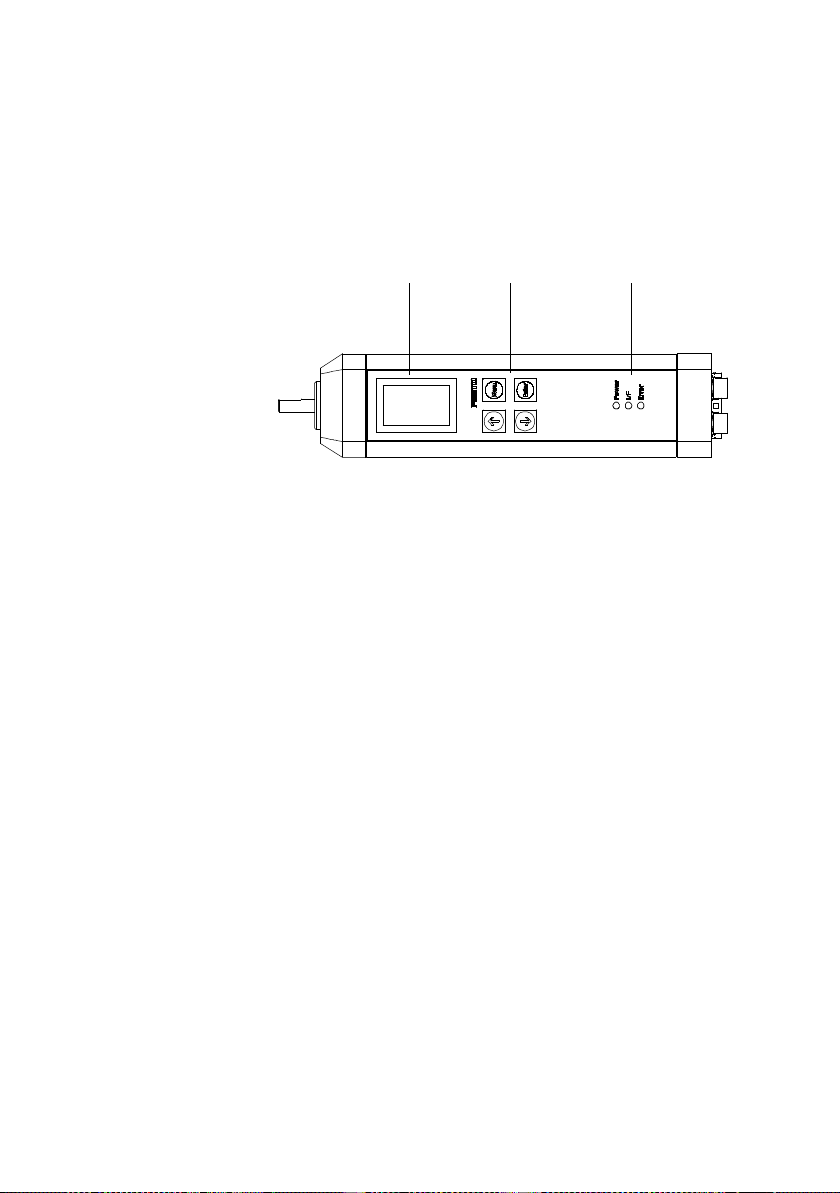
4. Control panel (only type MTR-DCI-...-H2)
4.1 Composition and function of the control panel
1
LC d ispla y
2
Operating
buttons
3
LEDs
– Power (green)
– I/F (green/red)
– Error (red)
Fig. 4/1: Control panel of the MTR-DCI-...-H2-...
LC display The graphic LCD (128 x 64 points) shows all texts in English.
The display can be turned in 180° steps, see menu command
[LCD adjustment].
Operating buttons The following settings and functions for commissioning are
enabled via menus using 4 keys of the touch-sensitive
keyboard:
1
2
3
– Parametrizing and referencing the drive
– Teaching standard applications and editing positioning
sets
– Processing/testing individual positioning sets.
LEDs The operating states are shown with 3 LEDs (see also
chapter 6.2).
– Power: Power supply
– I/F: Bus communication
Bus operating status: green
Bus connection: red
– Error: Error
4-4
Festo P.BE-MTR-DCI-CO-EN en 1209a
Page 77
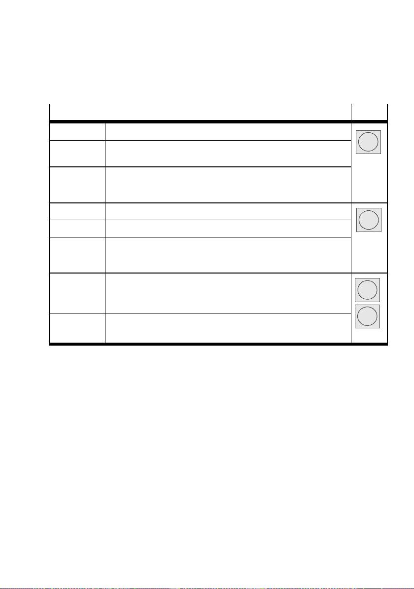
4. Control panel (only type MTR-DCI-...-H2)
Functio n Button
MENU Activates the main menu from the status display.
ESC Rejects the current entry and switches back in stages to the higher-order
menu level or status display.
EMERG.STOP interrupts the current positioning procedure (> Error mode; confirm
with <Enter>, then automatic return to the status display)
Only when HMI = on
OK Confirms the current selection or entry.
SAVE Saves parameter settings permanentlyin the EE PROM.
START/STOP Starts or stops a positioning procedure (only in Demo mode).
After stop: Display of current position; use <Menu> to return to th e
higher-order menu level.
<- -> Scrolls within a menu level in order to select a menu command.
EDIT Sets parameters.
Tab. 4/1: Button function (overview)
Menu
Enter
v
V
Festo P.BE-MTR-DCI-CO-EN en 1209a
4-5
Page 78

4. Control panel (only type MTR-DCI-...-H2)
4.2 The menu system
4.2.1 Accessing the main menu
MTR-DCI...
= 0.00 mm
X
a
HMI:off
<Menu>
When the power supply is switched on, the MTR-DCI automatically carries out an internal check. At first the display
briefly shows the Festo Logo then changes to the status display. The status display shows the following information:
– the type designation of your MTR-DCI,
– the current position of the drive x
– the current setting of the device control
(HMI = Human Machine Interface).
The current button function will be displayed in the lower
lines of the display:
<Menu> The main menu is accessed from the status dis-
4.2.2 Selecting a menu command
} Diagnostic
Positioning
Settings
S ESC <Menu>
<--> OK <Enter>
} HMI control
LCD adjustment
s ESC <Menu>
<--> OK <Enter>
<- -> With the arrow buttons on the control panel you
ESC With the <menu> button you can interrupt the
OK With the <Enter> button you can confirm the cur-
= ...,
a
play with the <Menu> button.
can select a menu command from the list. The
current selection is marked with an arrow ( }
Diagnostic). Select S in order to display further
menu commands.
current entry and return to the status display
or from a sub-menu to the higher-order menu.
rent selection or entry.
4-6
Festo P.BE-MTR-DCI-CO-EN en 1209a
Page 79
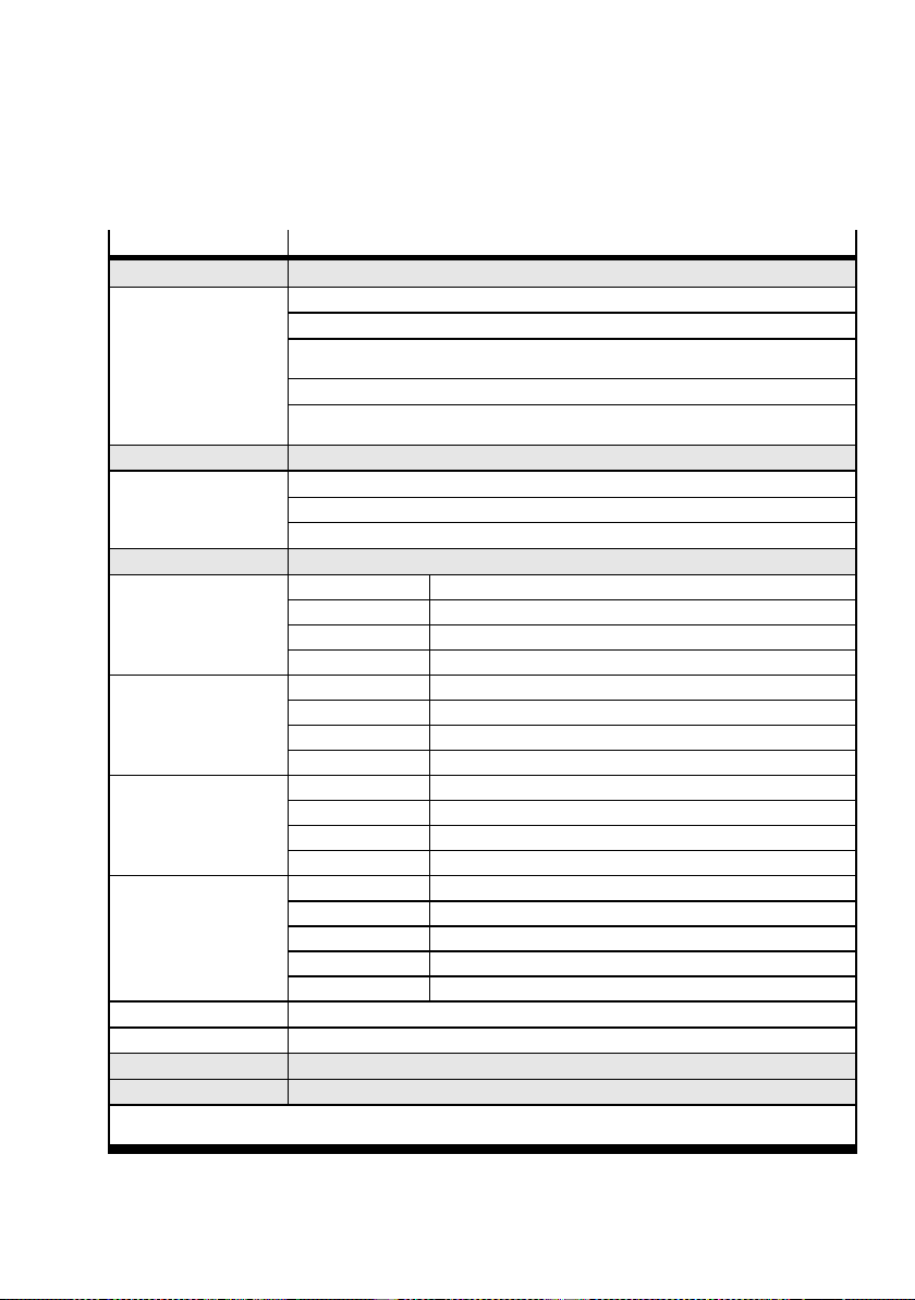
4. Control panel (only type MTR-DCI-...-H2)
Menu command Description
} Diagnostic Displays the system data and the currently effective settings (see chapter 4.3)
} Po s. set table Displays the po sition record table
} Axi s parameters Displays axis parameters and data
} System
paramet.
} CAN Bus Diag Displays data for CANopen diagnosis
} Softw are
information
} Positioning
} Move posit. set Start positioning run “Position set”
} Demo posit. tab Start positioning run “Position set table”
} Homing Star t the reference run
} Settings
} Axis type
} Axi s parameters
} Homing
parameter
} Po sition set
} Password edit Set up a local password with 3 figures for the control panel (see chapter 4.5)
} CAN parameter Setting the field bus parameter
} HMI control
} LCD adjus tme nt Rotate the display in steps of 90°
1)
If necessary password protection3)Teach mode
2)
Controller interface must be deactivated, see [HMI] control] :HMI = on
1) 2)
1) 2)
1)
Displays system parameters and system data
Displays the operating system version (firmware)
Reference run and positioning runs for testing the po sition records (see chapter 4.4)
Selection of the drive, parametrizing, programming the position sets ... (see chapter 4.5)
} Type DM ES-... Valve actuator DM ES-...
} Type DNCE-... Electric cylinder DNCE-...
} Rotation drive Rotation axis with stop
} User config Any linear drive
} Zero point
} Abs.min.po s
} Abs.max.pos3)Stroke limitation: Software end position, positive
} SAVE... Sav e parameters in EEPROM
} Homing method Select referencing (h oming) method (stop, software limit switch...)
} Velocity v_sw Positioning speed for searching for the reference point
} Velocity v_s0 Positioning speed for moving to the axis zero point
} SAVE... Sav e parameters in EEPROM
} Position nr. Number of the position record (0...14)
} Pos set mode Absolute or relative positioning
} Position
} Ve lo ci ty Positioning speed of the position set
} SAVE... Sav e parameters in EEPROM
Presetting the device control via the control panel (see chapter 4.6)
3)
Offset axis zero point
3)
Stroke limitation: Software end position, negative
3)
Target position of the position set
Tab. 4/2: Menu commands (overview)
Festo P.BE-MTR-DCI-CO-EN en 1209a
4-7
Page 80

4. Control panel (only type MTR-DCI-...-H2)
4.3 [Diagnostic] menu
In order to display the currently effective settings in the
positioning set table, axis and system parameters as well as
status and diagnostic information for bus communication and
for firmware version:
} Diagnostic
Pos.set table
Axis parameter
System paramet.
CAN-BUS Diag
Sodtware
information
1. Select the [Diagnostic] menu in the main menu.
2. Select a menu command (see Tab. 4/3 and Tab. 4/4).
<- -> You can scroll through the data with the arrow
buttons.
ESC With the <Menu> button you can return to the
higher-order menu.
4-8
Festo P.BE-MTR-DCI-CO-EN en 1209a
Page 81

4. Control panel (only type MTR-DCI-...-H2)
Menu command Description
[Pos. set table] No. Number of the position set
a/r – a = absolute positioning
– r = relative positioning
Pos Target position
Vel Positioning speed
[Axis parameter]
v
max
x
min
x
max
x
0
feed
2)
Maximum positioning speed
Stroke limitation: Software end position, negative
Stroke limitation: Software end position, positive
Offset axis zero point
Feed constant
1)
[System param] Vpower Supply voltage [V]
Imax Maximum current [A]
Iact Actual current [A]
Temp Operating temperature [°C]
Cycle Number of positioning movements
Ref.switch Reference switch (ON/OFF)
Mode Measuring system e.g. mm
Hom.meth. – bl.pos Fixed sto p in positive direction
– bl.neg Fixed stop in negative direction
– sw.pos Reference switch in positive direction
– sw.neg Reference switch in negative direction
Gear Gear reduction of the motor unit ( e.g. 6.75)
1)
Measuring unit depends on set measuring system
2)
not for ax is type “Rotation drive”
Tab. 4/3: [Diagnostic] menu (1)
Festo P.BE-MTR-DCI-CO-EN en 1209a
4-9
Page 82

4. Control panel (only type MTR-DCI-...-H2)
Menu command Description
[CAN-BUS-Diag] Bus diagnosis
– Guarding error1)“Node guarding” activated (if enabled in master),
–CAN
WarningLimit
– CO status
stopped
– CO status
pre-op
– State
operational
Bit rate S et bit rate of the MTR-DCI:
Profiles Pre-set data profile.
CAN Node ID CAN address of the MTR-DCI (hexadecimal/decimal).
Volt.supply int./ext. CAN interface voltage supply internal/external
e.g. master shut down or cable break.
Telegrams not being received or cannot be sent (no ac-
1)
knowledgementatlowestCANlevel),e.g.nobusconnection.
“Stop” network management command received.
Pre operational, normal state after power-on before the
master transmits “Start node operational”.
“Start node operational” transmitted by master, normal
operating state.
Value s:
1000k (1 Mbit/s), 800k, 500k, 800k, 125k, 100k, 50k,
20k (20 kBit/s)
Controller or device profile used for communication
between the CAN master and the MTR-DCI.
– FHPP: The MTR-DCI is controlled as per the Festo
Handling and Positioning Profile.
–
CiA
402: The MTR-DCI is controlled as per
CiA
402.
[Software
information]
1)
The “Guarding Error” and “CAN WarningLimit” state displays are prioritized (regardless of the
other states).
Version of the firmware of the MTR-DCI, e. g. V1.20
Tab. 4/4: [Diagnostic] menu (2)
4-10
Festo P.BE-MTR-DCI-CO-EN en 1209a
Page 83
4. Control panel (only type MTR-DCI-...-H2)
4.4 [Positioning] menu
Warning
Damage to or impairment of the mechanical components
With all positioning procedures the motor turns or the
connected axis starts to move.
•
Make sure that:
– nobody can place his/her hand in the positioning
range
– there are no objects within the positioning path.
Note
•
Before starting the reference run, make sure that:
– the positioning system is set up and wired
completely, and is supplied with power.
– the parameterizing is completed.
•
Do not start a positioning run until the reference system
has been defined by means of a reference run (see
chapter 4.4 .3).
Festo P.BE-MTR-DCI-CO-EN en 1209a
Note
Please note that position records with speed v = 0 or
invalid target positions ( -> error TARGET POSITION OUT OF
LIMIT) cannot be executed.
4-11
Page 84
4. Control panel (only type MTR-DCI-...-H2)
Selecting positioning travel or reference travel:
} Positioning
Move position set
Demo posit tab
Homing
1. Select the menu [Positioning] in the main menu.
2. Select the menu command:
– [Move position set] for testing a certain position set in
the position record table (see chapter 4.4.1).
– [Demo posit tab] in order to execute all position sets
in the position record table one after the other.
– [Homing] reference travel for determining the measur-
ing system (see chapter 4.4.3).
4.4.1 [Positioning] [Move position set]
Note
Do not start a positioning run until the reference system
has been defined by means of a reference run.
For testing a particular position record in the position record
table.
1. Select the number of the position set.
Move position set
Position no.
[1...31] = _?
EDIT <--> OK <Enter>
ESC <Menu>
<- -> You can set the desired number with the arrow
buttons.
OK You can accept the selection with the <Enter> button.
ESC With the <Menu> button you can interrupt the activ-
ity and return to the higher-order menu.
Move position set
Attention! Motor moves
ESC <Menu>
START <Enter>
4-12
2. Start the positioning procedure with START <Enter>.
During positioning travel the following information is
displayed:
– the active positioning set e.g. Pos 2
Festo P.BE-MTR-DCI-CO-EN en 1209a
Page 85

4. Control panel (only type MTR-DCI-...-H2)
Move position set
Pos 2
x
= 220 mm
t
v = 22 mm/s
x
= 200 mm
a
EMERG.STOP<Menu>
– the target position xt
– the positioning speed v
– the current position xa.
EMERG.
STOP
With the <Menu> button you can interrupt the
current positioning procedure (> MOTOR
STOP fault).
Move posit set
Pos 2
= 220 mm/s
xt
v = 22 mm/s
xa = 220 mm/s
ESC<Menu>
When positioning travel is completed:
ESC With the <Menu> button you can return to the
selection of the positioning set.
4.4.2 [Positioning] [Demo position table]
Theremustbeatleasttwopositionrecordsinthememory.
If the position record table contains a position record with
speed v = 0, this position record and all the following sets will
not be executed; the positioning run will be continued with
position record 1.
In order to execute all position sets in the position record
table one after the other:
Demo position table
Attention! Motor moves
ESC <Menu>
START <Enter>
Demo position table
Pos 2
x
= 220 mm
t
v = 22 mm/s
x
= 220 mm
a
DEMO STOP<Enter>
EMERG.STOP<Menu>
Festo P.BE-MTR-DCI-CO-EN en 1209a
•
Start the positioning procedure with START <Enter>.
During positioning travel the following information is displayed:
– the active position set e.g. Pos 2
– the target position xt
– the positioning speed v
– the current position xa.
4-13
Page 86

4. Control panel (only type MTR-DCI-...-H2)
DEMO
STOP
EMERG.
STOP
4.4.3 [Positioning] [Homing]
Note
•
Note also the instructions on carrying out reference
travel in chapter 5.2.
First set the parameter in the menu [Settings] [Homing parameter]. (see chapter 4.5.3). Factory setting: Referencing to
reference switch in negative direction.
Homing
Warning Motor moves.
ESC<Menu>
START <Enter>
Defining the reference point by means of reference travel
•
Start reference travel with START <Enter>.
The following information is displayed:
You can interrupt the positioning procedure with
<Enter>.
The current position set will be executed before
the axis stops. With a new start processing begins again with the first position set
.
With the <Menu> button you can interrupt the
positioning procedure (> MOTOR STOP fault).
Homing
V_sw = 20 mm/s
v_s0 = 10 mm/s
EMERG.STOP<Menu>
4-14
– the search speed v_sw for moving to the reference point
[Velocity v_sw]
– the positioning speed v_s0 for moving to the axis zero
point v_0.
During reference travel the drive moves slowly at reduced
search speed to the stop or reference switch and accepts the
position as the reference point.
Festo P.BE-MTR-DCI-CO-EN en 1209a
Page 87

4. Control panel (only type MTR-DCI-...-H2)
EMERG.
STOP
With the <Menu> button you can interrupt the
reference travel (> HOMING ERROR fault).
•
Acknowledge the error message with
<Enter>.
•
Repeat the reference run.
After successful reference travel the menu [Positioning] will
be shown.
Festo P.BE-MTR-DCI-CO-EN en 1209a
4-15
Page 88
4. Control panel (only type MTR-DCI-...-H2)
4.5 Menu [Settings]
The menu [Settings] contains all functions necessary for
parametrizing the axis system and the position sets. Further
iinformation on the individual menu commands can be found
in the chapters specified (see Tab. 4/5).
} Settings
Axis type
Axis parameter
Homing paramet.
Position set
Password edit
CAN parameter
[Settings]
[Axis type] Select the axis driven by the MTR-DCI 4.5.1
[Axis parameter] Teach mode for setting the axis parameters 4.5.2
[Homing paramet.] Setting the reference travel method and the speed during
[Position set] Teach mode for programming the position record table 4.5.4
[Password edit] Setting up a local password with 3 figures for the control panel 4.5.5
[CAN parameter] Setting the field bus parameters 4.5.6
Description Chapter
reference travel
1. Select the menu [Settings] in the main menu.
2. Select a menu command.
4.5.3
Tab. 4/5: Menu [Settings]
Note
The set parameters take effect immediately after confirmation with OK <ENTER>. The settings are saved permanently
in EEPROM with the [SAVE...] menu c ommand:
•
Choose [SAVE...] to save the parameter settings. Only
then will the settings be retained even when the power
supply is switched off or if there is a power failure.
4-16
Festo P.BE-MTR-DCI-CO-EN en 1209a
Page 89
4. Control panel (only type MTR-DCI-...-H2)
4.5.1 [Settings] [Axis type]
SelecttheaxisdrivenbytheMTR-DCI
[Axis type]
[Type DMES-...] Festo servo axis
[Type DNCE-...] Festo electrocylinder
[Rotationdrive] Specific rotation axis
[User config] Specific linear axis
Description
Tab. 4/6: Menü [Settings] [Axis type]
<- -> With the arrow keys you can set the axis-specific
features e.g. feed constant, measuring system or
counting direction according to the entry request.
(details see chapter 5.2.1).
SAVE You can save the settings permanently in EEPROM
with the <Enter> button
ESC With the <Menu> button you can interrupt the
activity and return to the higher-order menu.
•
Save the settings with SAVE <Enter>.
Festo P.BE-MTR-DCI-CO-EN en 1209a
4-17
Page 90
4. Control panel (only type MTR-DCI-...-H2)
4.5.2 [Settings] [Axis parameter]
Teach mode for setting the axis parameters
•
In order to set the measuring system select the following
parameters. Observe the instructions in chapter 5.2.4.
[Axis parameter]
[Zero point] Offset axis zero point
[Abs.min.pos] Stroke limitation: Software end position,
[Abs.max.pos] Stroke limitation: Software end position,
[SAVE...] Save parameters in EEPROM
Description
negative
positive
Tab. 4/7: Menu [Settings] [Axis parameter]
<- -> You can move the axis into the desired position with
the arrow buttons.
OK You can accept the selection with the <Enter> button.
ESC With the <Menu> button you can interrupt the activ-
ity and return to the higher-order menu.
•
Choose [SAVE...] to save the parameter settings. Only then
will the settings be retained even when the power supply
is switched off or if there is a power failure.
4-18
Festo P.BE-MTR-DCI-CO-EN en 1209a
Page 91
4. Control panel (only type MTR-DCI-...-H2)
4.5.3 [Settings] [Homing paramet.]
Setting the reference travel method and the speed during
reference travel. Observe the instructions in chapter 5.2.2.
The maximum speed during reference travel is limited to half
the maximum positioning speed v_max (v_max see [Diagnostics] [Axis parameter] ).
[Hom. paramet.]
[Homing method] sw.neg
[Velocity v_sw] v_sw Speed for searching for the reference point
[Velocityv_s0] v_s0 Speed for moving to the axis zero point
[SAVE...] Save parameters in EEPROM
Param. Description
(switch negative)
sw.pos
(switch positive)
bl.neg
(block negative)
bl.pos
(block positive)
Homing to reference switch, negative = factory setting
Homing to reference switch, positive
Homing to fixed stop, negative
Referencing to
fixed stop, positive
Tab. 4/8: Menu [Settings] [Homing paramet.]
•
Choose [SAVE...] to save the parameter settings.
Festo P.BE-MTR-DCI-CO-EN en 1209a
4-19
Page 92

4. Control panel (only type MTR-DCI-...-H2)
4.5.4 [Settings] [Position set]
Programming the position record table
•
Select the number of the desired position set. The following settings refer to the currently selected position set.
Note also the instructions on programming the position
sets in chapter 5.2.5.
[Position set]
[Position no.] No. Number of the position set
[Pos set mode] [absolute/
[Position] xt Teach mode for setting the target position in the selected
[Velocity] v Positioning speed in the selected measuring system e.g. [mm/s]
[SAVE...] Save parameters in EEPROM
Param. Description
relative]
Positioning mode
absolute = absolute position specification, related to the
project zero point
relative = relative position specification, related to the current
position
measuring system e.g. [mm].
Do not teach the positions until the reference system has been
defined by means of a reference run. (see chapter 4.4.3)
Tab. 4/9: Menü [Settings] [Position set]
<--> Youcanmovetheaxisintothedesiredpositionor
select the parameter setting with the arrow buttons.
OK You can accept the selection with the <Enter> button.
ESC With the <Menu> button you can interrupt the activ-
ity and return to the higher-order menu.
4-20
•
Choose [SAVE...] to save the parameter settings. Only then
will the settings be retained even when the power supply
is switched off or if there is a power failure.
Festo P.BE-MTR-DCI-CO-EN en 1209a
Page 93

4. Control panel (only type MTR-DCI-...-H2)
4.5.5 [Settings] [Password edit]
In order to prevent unauthorized or unintentional overwriting
or modification of parameters in the device, access via the
control panel can be protected by a (local) password. No
password has been preset at the factory (presetting = 000).
•
KeepthepasswordfortheMTR-DCIinasafeplace,
e.g. with the internal documentation for your system.
If the active password in the MTR-DCI should be lost in spite
of care being taken:
the password can be deleted by entering a master password.
In this case please contact your Festo Service partner.
Activate password
Select the menu [Settings] [Password edit].
New Password:
[?xx] =
ESC<Menu>
EDIT <--> OK <Enter>
Enter a password with 3 figures (0...9). The current entry
position is marked with a question mark.
1. Use the arrow buttons to select a figure.
Festo P.BE-MTR-DCI-CO-EN en 1209a
2. Confirm your entry with <Enter>.
3. Set a figure for the next entry position “?”.
4. After entering the third figure, save the password with
SAVE <Enter>.
After saving, access to all parameter functions and control
functions of the control panel is only possible with a password access blocked.
4-21
Page 94

4. Control panel (only type MTR-DCI-...-H2)
Enter password
Enter Password:
[?xx] =
EDIT <--> OK <Enter>
ESC<Menu>
As soon as a password is active, it will be scanned automatically when the menu commands [Positioning], [Settings] or
[HMI control] are accessed.
The current entry position is marked with a question mark.
1. Use the arrow buttons to select a figure 0...9.
2. Confirm your entry with <Enter>. The next entry position
will be displayed.
3. Repeat the entry for the remaining entry positions.
When the correct password is entered, all parameterising and
control functions of the control panel are enabled until the
power supply is switched off.
Modify/deactivate password
Enter Password:
[?xx] =
EDIT <--> OK <Enter>
New Password:
[?xx] =
EDIT <--> OK <Enter>
ESC<Menu>
ESC<Menu>
4-22
Select the menu [Settings] [Password edit].
Enter the previous password with 3 figures 0...9. The current
entry position is marked with a question mark.
1. Set the first figure of the previous password with the
arrow buttons.
2. Confirm the figure with OK <Enter>.
3. Set the figure for the next entry position “?”.
After selecting the 3rd. figure of the previous password,
you can modify or deactivate the password.
Enter the new password with 3 figures or “000” in order
to deactivate the old password:
4. Use the arrow buttons to select the first figure.
Festo P.BE-MTR-DCI-CO-EN en 1209a
Page 95

4. Control panel (only type MTR-DCI-...-H2)
5. Confirm the figure with <Enter>.
6. Set the figure for the next entry position “?”.
7. After selecting the 3rd. figure, save your setting with SAVE
<Enter>.
4.5.6 [Settings] [
[CAN parameters]
[CAN Node ID] 1 ... 127
[CAN bit rate] 1000 kBd,
[CAN profiles] CiA 402,
[CAN Volt.Supply] internal,
CAN parameters]
Param. Description
(1 ... 7fh)
800 kBd,
500 kBd,
250 kBd,
125 kBd,
100 kBd,
50 kBd,
20 kBd
FHPP
external
Setting the field bus parameters
Field bus address of the MTR-DCI.
Representation:
“1 dec, 1 hex”...“127 dec, 7f hex”
Fieldbus bit rate corresponding to the settings of the master.
Pre-set data profile.
Controller or device profile used for communication between the
CAN master and the MTR-DCI.
–
CiA
402:
The MTR-DCI is controlled as per
– FHPP:
The MTR-DCI is controlled as per the Festo Handling and Positioning Profile.
only MTR-DCI 42,52,62: Supply for the CAN interface,
see chapter 3.6. and 5.2.7
CiA
402.
Tab. 4/10: Menu [Settings] [C AN parameter]
Festo P.BE-MTR-DCI-CO-EN en 1209a
4-23
Page 96

4. Control panel (only type MTR-DCI-...-H2)
<- -> You can select the parameter setting with the arrow
buttons.
OK You can accept the selection with the <Enter> button.
ESC With the <Menu> button you can interrupt the activ-
ity and return to the higher-order menu.
The settings in the menu [CAN parameter] are saved directly
and permanently (including in the event of a power failure) in
the EEPROM after confirmation with OK <Enter>.
4-24
Festo P.BE-MTR-DCI-CO-EN en 1209a
Page 97

4. Control panel (only type MTR-DCI-...-H2)
4.6 Menu command [HMI control]
HMI control
[on/off] = on?
HMI Access free
<--> OK <Enter>
ESC<Menu>
In order to select the menu commands [Positioning] and
[Settings], you must enter the setting “HMI on”. Only then is
the MTR-DCI ready to process user entries on the control
panel.
When selecting the menu commands you will be requested to
modify the HMI setting.
You can also modify the setting directly with the menu command [HMI control].
1)
HMI
on The device is controlled manually via the control panel. The control interface of the MTR-
off The device control is carried out via the control interface of the MTR-DCI.
1)
Description
DCI is deactivated and the control enable is set. The actual status of the FHPP control
bytes or the transmitted CiA 402 control word is then ineffective. With activated control
via the control panel, the drive cannot be stopped with the STOP bit.
Human Machine Interface
Tab. 4/11: States [HMI control]
<- -> You can select the parameter setting with the arrow
buttons.
OK You can accept the selection with the <Enter> button.
ESC With the <Menu> button you can interrupt the activ-
ity and return to the higher-order menu.
Festo P.BE-MTR-DCI-CO-EN en 1209a
Access to the MTR-DCI via HMI and FCT can be blocked via
the field bus as follows:
– FHPP: Bit CCON.B5, “HMI Access locked”.
4-25
Page 98

4. Control panel (only type MTR-DCI-...-H2)
4-26
Festo P.BE-MTR-DCI-CO-EN en 1209a
Page 99

Commissioning
Chapter 5
Commissioning
Festo P.BE-MTR-DCI-CO-EN en 1209a
5-1
Page 100

5. Commissioning
Contents
5. Commissioning 5-1................................................
5.1 Procedure for commissioning 5-4.....................................
5.2 Commissioning with the control panel (only MTR-DCI-...H2) 5-7.............
5.2.1 Setting the axis type 5-9.....................................
5.2.2 Setting the reference travel parameters 5-10.....................
5.2.3 Starting a reference run 5-13..................................
5.2.4 Teach the axis zero point AZ and the software end positions 5-16.....
5.2.5 Teach position records 5-18...................................
5.2.6 Test run 5-20...............................................
5.2.7 Setting CAN parameters 5-22..................................
5.3 Commissioning with FCT 5-26.........................................
5.3.1 Installing the FCT 5-27........................................
5.3.2 Procedure 5-28.............................................
5.4 CommissioningonaCANopenmaster 5-30..............................
5.4.1 Overview of commissioning on the field bus 5-31..................
5.4.2 Configuration of the CANopen master (“I/O configuration”) 5-32.....
5.4.3 Communication 5-33.........................................
5.4.4 PDO mapping 5-34...........................................
5.5 Festo profile for handling and positioning (FHPP standard) 5-37.............
5.5.1 Supported operating modes 5-37...............................
5.5.2 Composition of the cyclic I/O data (FHPP standard) 5-39............
5.5.3 Description of the I/O data (Record select) 5-41...................
5.5.4 Description of the I/O data (Direct mode) 5-42....................
5.5.5 Description of the control bytes CCON, CPOS, CDIR 5-43............
5.5.6 Description of the status bytes SCON, SPOS, SDIR (RSB) 5-46.......
5.5.7 Examples of the I/O data 5-49.................................
5.6 Sequence control as per FHPP standard 5-62............................
5.6.1 Homing 5-62................................................
5.6.2 Jog mode 5-64..............................................
5.6.3 Teaching via field bus 5-66....................................
5-2
Festo P.BE-MTR-DCI-CO-EN en 1209a
 Loading...