

Page 1
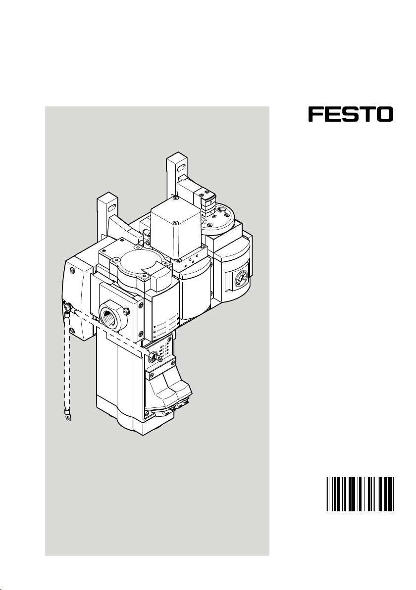
MSE6-C2M
Energy efficiency module
Description| Commissioning, Function, Electronics
8095305
8095305
2019-03
[8095307]
Page 2

Translation of the original instructions
PI PROFIBUS PROFINET® is a registered trademark of its respective trademark holder in certain countries.
2 Festo — MSE6-C2M — 2019-03
Page 3

Table of contents
1 Applicable documents................................................................................................. 5
2 Safety........................................................................................................................... 5
2.1 Safety instructions........................................................................................................ 5
2.2 Intended use................................................................................................................ 5
2.3 Foreseeable misuse...................................................................................................... 5
2.4 Training of qualified personnel..................................................................................... 6
3 Additional information................................................................................................ 6
4 Service..........................................................................................................................6
5 Product overview......................................................................................................... 7
5.1 Design........................................................................................................................... 7
5.1.1 Product design........................................................................................................7
5.1.2 Display components............................................................................................... 7
5.1.3 Connecting components......................................................................................... 8
5.2 Functions...................................................................................................................... 9
5.3 Electrical system configuration..................................................................................... 12
5.4 Combination with MS6 modules................................................................................... 14
6 Commissioning............................................................................................................ 14
6.1 Safety............................................................................................................................ 14
6.2 Commissioning the product.......................................................................................... 15
6.3 Commissioning with bus node CPX-M-FB34................................................................. 16
6.3.1 Interfaces and display components........................................................................ 16
6.3.2 Using the memory card........................................................................................... 17
6.3.3 Network interface................................................................................................... 18
6.3.4 Setting the DIL switches..........................................................................................19
6.3.5 Commissioning and configuration...........................................................................21
6.3.6 Faultless commissioning, normal operating status................................................. 23
7 Measuring and control function.................................................................................. 23
7.1 Flow rate....................................................................................................................... 23
7.2 Consumption................................................................................................................ 24
7.3 Pressure....................................................................................................................... 25
7.4 Pressure change........................................................................................................... 27
7.4.1 Method of measurement.........................................................................................27
7.4.2 Function structure...................................................................................................29
7.5 Pressure regulation and blocking function................................................................... 29
7.5.1 Overview.................................................................................................................29
7.5.2 User-controlled pressure regulation and blocking function (USER).........................30
7.5.3 Automatic pressure regulation and blocking function (AUTO).................................31
7.5.4 Functional states.................................................................................................... 34
7.5.5 Function structure...................................................................................................35
7.6 Electrical inputs............................................................................................................ 37
3Festo — MSE6-C2M — 2019-03
Page 4

7.7 Electrical outputs...........................................................................................................38
8 Input/output data.........................................................................................................39
8.1 Overview....................................................................................................................... 39
8.2 Description of I/O data.................................................................................................. 41
8.2.1 Output word Am.0 "Module control" [Modul control]............................................. 42
8.2.2 Output word Am.1 "Input address" [Input address]............................................... 43
8.2.3 Output word Am.2 "Pressure setpoint P2" [Set point pressure P2]........................ 44
8.2.4 Input word Em.0 "Flow rate" [Flow]....................................................................... 44
8.2.5 Input word Em.1 "Consumption" [Consumption]................................................... 45
8.2.6 Input word Em.2 "Pressure P2" [Pressure P2]........................................................ 46
8.2.7 Input word “Pressure change DP2"....................................................................... 46
8.2.8 Input word Em.3 “Module status” [Status]............................................................. 47
8.3 Selectable input data function.......................................................................................49
8.3.1 Procedure.............................................................................................................. 49
8.3.2 Output word Am.1 "Input address" [Input address]............................................... 50
8.3.3 Input word Em.4 “Selected input address” [Selected input address]...................... 51
8.3.4 Input word Em.5 "Selected input data word" 0 [Selected input data word 0]......... 51
8.3.5 Input word Em.6 Selected input data word 1 [Selected input data word 1]............. 52
8.3.6 Selectable 32-bit input data with permanently assigned address...........................52
8.3.7 Selectable, freely combinable 16-bit input data with address to be calculated.......53
9 Parameter.....................................................................................................................55
9.1 Overview of module parameters....................................................................................55
9.2 Modifiable module parameters......................................................................................58
9.3 Read-only module parameters.......................................................................................72
10 Diagnostics...................................................................................................................73
10.1 Error numbers................................................................................................................74
11 Commissioning examples of parameterisation............................................................ 78
11.1 Commissioning example – automatic shut-off function................................................. 78
11.2 Commissioning example – monitoring of pressure drop................................................ 81
4 Festo — MSE6-C2M — 2019-03
Page 5
Applicable documents
1 Applicable documents
All available documents for the product èwww.festo.com/pk.
Document Product Contents
Instructions Energy efficiency module MSE6-C2M-IN Operating, Assembly
Description CPX system description P.BE-CPX-SYS-… Installation, Commis-
sioning
Description PROFINET bus node IO P.BE-CPX-PNIO-… PROFINET
Instructions Wall mounting-SET MS6-WPG Assembly
Tab. 1 Documentation on the product
2 Safety
2.1 Safety instructions
– Only use the product in original status without unauthorised modifications.
– Only use the product if it is in perfect technical condition.
– Only use the product in an industrial environment.
– This product can generate high frequency malfunctions, which may make it necessary to imple-
ment interference suppression measures in residential areas.
– Observe labelling on the product.
– Prior to mounting, installation and maintenance work: Switch off power supply and secure it from
being switched back on. Only switch on the power supply when the product has been assembled
and installation and maintenance work is complete.
– Product is opened in normal position (pressurisation status). If the minimum supply voltage is not
reached, the shut-off valve of the product switches to the pressurisation status.
– Note that, when the input pressure is switched off, depending on the function a residual pressure
of <1bar (<0.1MPa) can remain at the output.
2.2 Intended use
The energy efficiency module MSE6-C2M monitors and optimises the compressed air consumption via
an adjustable outlet pressure.
2.3 Foreseeable misuse
The following examples of foreseeable misuse are among those not approved as intended use:
– Outdoor use
– Exhaust ports sealed
– Use of the integrated shut-off valve in continuous switching operation for pneumatic components
5Festo — MSE6-C2M — 2019-03
Page 6

Additional information
2.4 Training of qualified personnel
Installation, commissioning, service and disassembly should only be conducted by skilled personnel.
The skilled personnel must be familiar with the installation of electrical and pneumatic control systems.
3 Additional information
– Accessories èwww.festo.com/catalogue.
– Spare parts èwww.festo.com/spareparts.
– Information on the CPX field bus node èwww.festo.com/sp.
– Information on the short documentation for the CPX-Extension èwww.festo.com/sp.
4 Service
Contact your regional Festo contact person if you have technical questions èwww.festo.com.
6 Festo — MSE6-C2M — 2019-03
Page 7
Product overview
5 Product overview
5.1 Design
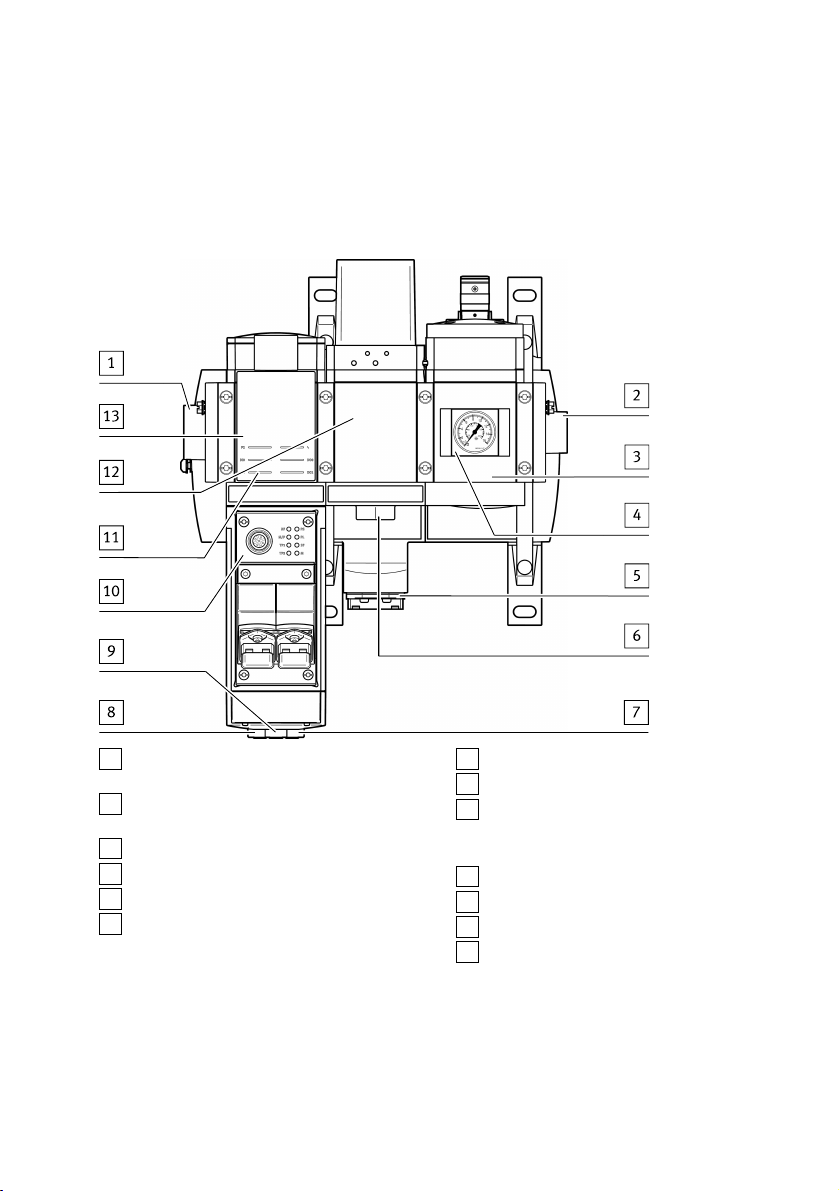
5.1.1 Product design
1
Pneumatic connection 1:
Input for compressed air
2
Pneumatic connection 2:
Output for compressed air
3
Shut-off valve with pressure sensor
4
Pressure gauge
5
Electrical system supply
6
Pneumatic connection 3:
Exhaust
Fig. 1 Product design
5.1.2 Display components
The product has two electrical inputs and two electrical outputs.
7
Connection for electrical inputs
8
Connection for electrical outputs
9
Only MSE6-C2M...-M: connection for CPXExtension series 1 for connecting devices
with CPX-Extension series 2 connection
10
PROFINET bus node CPX-M-FB34
11
Status LEDs
12
Proportional-pressure regulator
13
Flow sensor
7Festo — MSE6-C2M — 2019-03
Page 8
Product overview
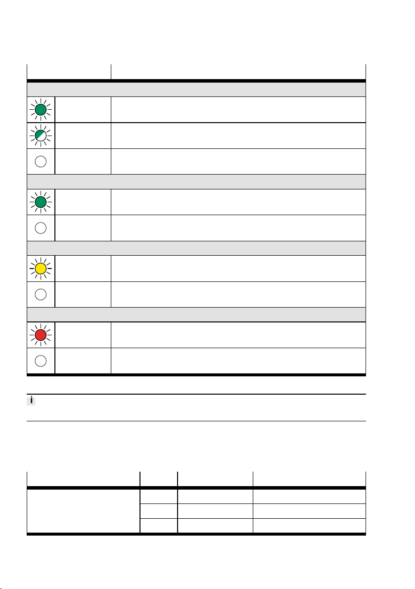
LED Meaning
P2 (green)
LED illumin-
Outlet pressure p2 ³ lower critical limit pressure p2
ated
LED flashes Outlet pressure p2 < lower critical limit pressure p2 and
Outlet pressure p2 ³ pressure setpoint auto standby –0.5bar
LED does not
Outlet pressure p2 < pressure setpoint auto standby –0.5bar
illuminate
DI0 and DI1 (green)
LED illumin-
Signal at electrical input 0 or 1 is present (logic 1)
ated
LED does not
Signal at electrical input 0 or 1 is not present (logic 0)
illuminate
DO0 and DO1 (yellow)
LED illumin-
Electrical output 0 or 1 sends 1-signal (logic 1)
ated
LED does not
Electrical output 0 or 1 sends 0-signal (logic 0)
illuminate
P Red
LED illumin-
Module error
ated
LED does not
No module error
illuminate
Tab. 2 Status LED display for module functions
Display elements bus node è 6 Commissioning.
5.1.3 Connecting components
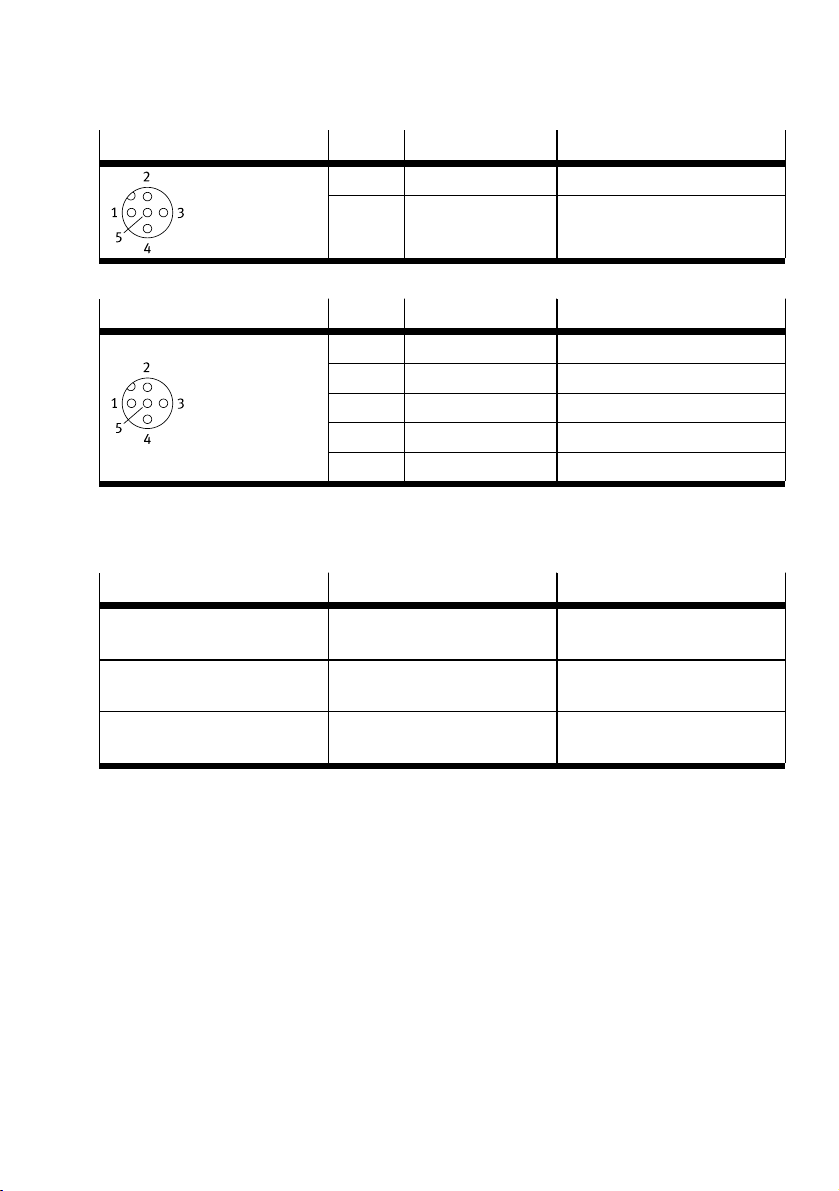
I/O connections
The product has two electrical inputs and two electrical outputs.
Plug Pin System supply Function
M12
1 24V DC U
SEN
Supply voltage
2 Input-1 Input 1
3 0V U
8 Festo — MSE6-C2M — 2019-03
SEN
0V load
Page 9
Product overview
Plug Pin System supply Function
4 Input-0 Input 0
5 FE Functional earth
Tab. 3 Electrical inputs DI0 and DI1
Plug Pin System supply Function
M12
1
–
Not assigned
2 Output-1 Output 1
3 0
VA
0V load
4 Output-0 Output 0
5 FE Functional earth
Tab. 4 Electrical outputs DO0 and DO1
I/O and CPX-Extension connections for MSE6-C2M-…(-M)
The product has two electrical inputs, two electrical outputs and a CPX-Extension series 1 connection.
Connection Position Plug
Electrical inputs Connections on the cover under
the bus node
Electrical outputs Connections on the cover under
the bus node
1)
CPX
Connections on the cover under
the bus node
1) extension only available for MSE6-C2M-…-M
Design: M12, 5-pin
Identification: X2
Design: M12, 5-pin
Identification: X1
Design: M12, hybrid, 8-pin
Identification: none
Tab. 5 Electrical inputs, electrical outputs and CPX-Extension
Bus node
The product has a PROFINET bus node CPX-M-FB34.
Only energy efficiency module MSE6-C2M-…-M
The product has a CPX-Extension series 1 connection. Use only the preassembled extension connecting cables from Festo èwww.festo.com/catalogue.
5.2 Functions
Overview
– Pressure regulation and blocking function (energy efficiency function)
– Automatic blocking and subsequent regulation to the standby target pressure with a pro-
longed reduced flow rate
– User-controlled blocking and pressure regulation
– Parameterisable target pressure rise limitation
9Festo — MSE6-C2M — 2019-03
Page 10

Product overview
– Recording and processing of measurement data
– Outlet pressure P2
– Pressure change (for pressure tightness testing)
– Flow rate
– Air consumption
– Limit monitoring
– Pressure, lower and upper critical limit
– Pressure change, upper critical limit
– Flow rate, upper critical limit value
– Electrical I/Os
– 2 digital inputs
– 2 digital outputs
– Channel-based status indicator via LED
– Parameterisable special functions
– Fieldbus connection
– e.g. PROFINET connection CPX-M-FB34
Standby detection and automatic pressure reduction
The product detects downtimes of a pneumatic system upon corresponding parameterisation. If the
parameterised flow rate critical limit is continuously not reached during the parameterised delay period, when the automatic function is activated (controller auto-user and controller auto-enable logic 1),
the supply air is blocked until the parameterised standby target pressure value is reached. The outlet
pressure is then adjusted to this value. This prevents unnecessary exhausting of the system and
enables leakage detection via an analysis of the pressure drop. A control signal can be used to switch
back over from standby pressure regulation to normal pressure regulation. When the automatic function is deactivated, the shut-off valve and the pressure regulator can be directly controlled by the
machine controller.
Regulation of the compressed air supply
The product regulates the compressed air supply to the set pressure setpoint. This can be done in
manual mode by the setting from the controller. In automatic mode, regulation takes place via the
parameterised target pressure values. Prerequisite: operating pressure P1 ³ target pressure + 1bar.
Pressure tightness testing
The product continuously measures the pressure change in the parameterised time interval and monitors this value to ensure it is not exceeded in the blocking status. The measured pressure change
serves as a measure of the leakage existing in the downstream system.
Pressure recording
The product continuously measures the outlet pressure, prepares the data and makes it available cyclically. To detect operating pressures that are too high or too low, the product offers the option of
parameterising critical limits for pressure. If the parameterised critical limit is exceeded, the product
will output a diagnostic message. The status of monitoring to ensure the critical limit is not exceeded
is indicated via an input bit and via the P2 LED on the module.
10 Festo — MSE6-C2M — 2019-03
Page 11

Product overview
Flow recording
The product continuously records the flow rate, prepares the data and makes it available cyclically. To
detect excessive flow rates, the product offers the option of parameterising the upper critical limit for
the flow rate. If the parameterised critical limit is exceeded, the product will output a diagnostic message.
Consumption recording
The product determines the compressed air consumption by recording the system flow rate. With the
aid of output data, the consumption measurement can be switched on and off and the consumption
value can be reset.
Operational functions
The behaviour of the product can be influenced by accessing the internal parameters, e.g.:
– Diagnostic behaviour by enabling maskable diagnostic messages
– Specification of the units and the measuring interval
– Setting of critical limits
The product is delivered with pre-set parameters. Information on parameterisation è 9 Parameter.
11Festo — MSE6-C2M — 2019-03
Page 12
Product overview
5.3 Electrical system configuration
The maximum permissible current load of the system supply for the MSE6-C2M-…-M (with CPX extension) is 6A.
The product is equipped with a field bus node. Input and output data as well as parameters and diagnostic information can be transferred to the higher-level controller via the field bus node. Power is
supplied via a separate supply port.
The MSE6-C2M-…-M product variant has a CPX-Extension Series 1 interface to which certain products
with a CPX-Extension Series 2 interface can be connected:
– 1 energy efficiency module MSE6-D2M or
– up to a maximum of 3 digital and/or analogue CPX input and output modules
The following CPX I/O modules are permitted:
– CPX-4DE (4 digital inputs)
– CPX-8DE (8 digital inputs)
– CPX-4DA (4 digital outputs)
– CPX-8DA (8 digital outputs)
– CPX-8DE/8DA (8 digital inputs and 8 digital outputs)
– CPX-4AE-U-I (4 analogue inputs)
– CPX-2AA-U-I (2 analogue outputs)
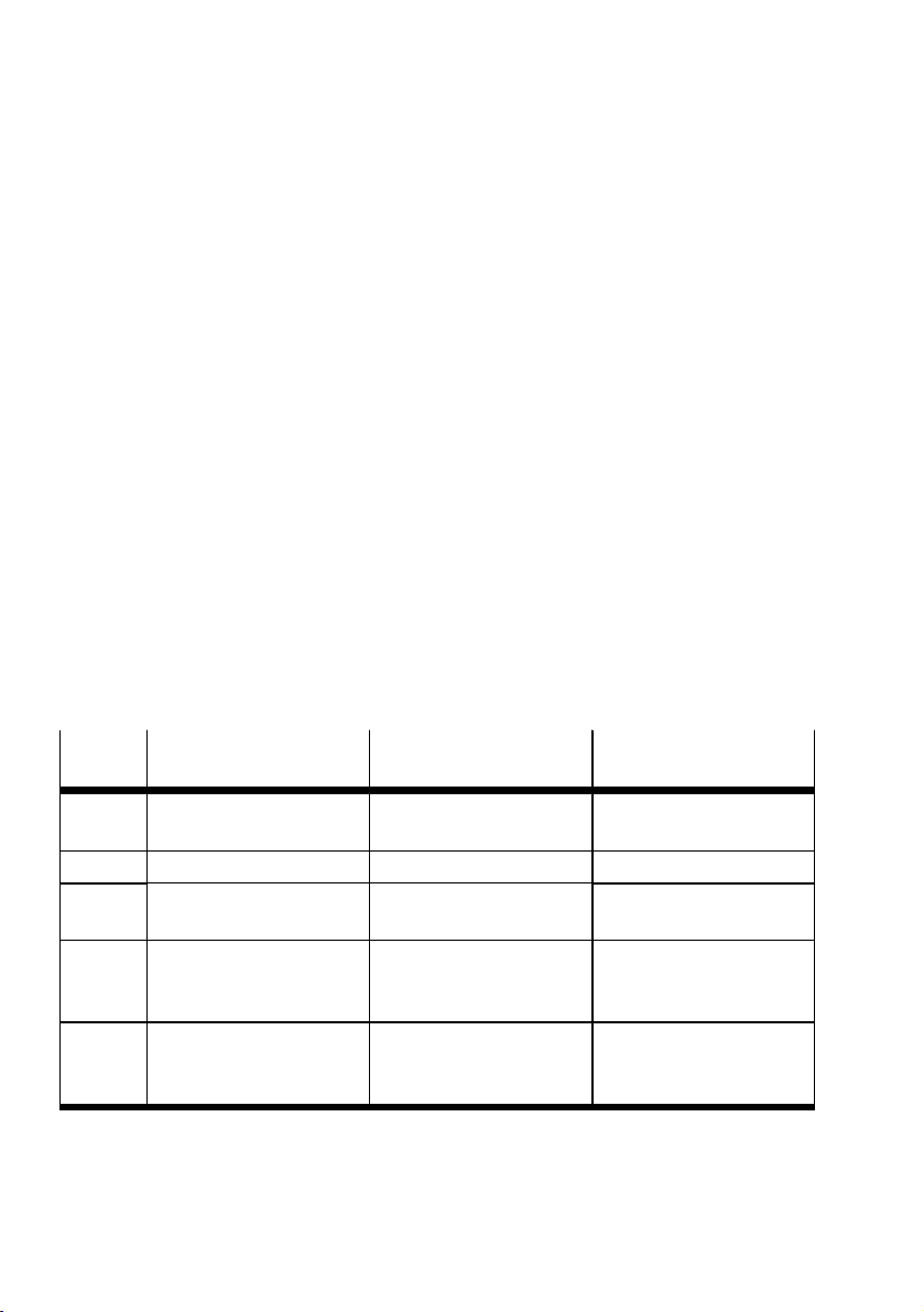
The MSE6-C2M consists of the energy efficiency module and field bus node sub-functions, each of
which is assigned its own fixed module number.
Additional modules can be connected to the MSE6-C2M-…-M via CPX-Extension. These form a complete system with the MSE6-C2M-...-M and have a consecutive module number (from module number
2).
Module
number
0 Energy efficiency module
MSE6-C2M-…
Individual device
MSE6-C2M
MSE6-C2M-…-M
with MSE6-D2M
Energy efficiency module
MSE6-C2M
MSE6-C2M-…-M
with CPX I/O modules
Energy efficiency module
MSE6-C2M
1 Bus node CPX-FBxx Bus node CPX-FBxx Bus node CPX-FBxx
2
3
–
– –
Energy efficiency module
MSE6-D2M
1st CPX I/O module in
CPX-Extension series 2
2nd CPX I/O module in
CPX-Extension series 2
(optional
4
– –
3rd CPX I/O module in
CPX-Extension series 2
(optional)
Tab. 6 Module numbers
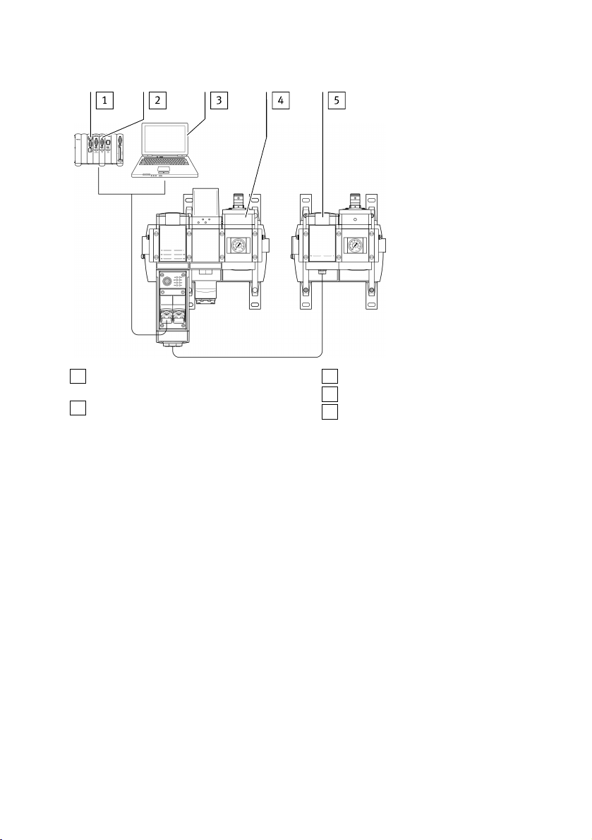
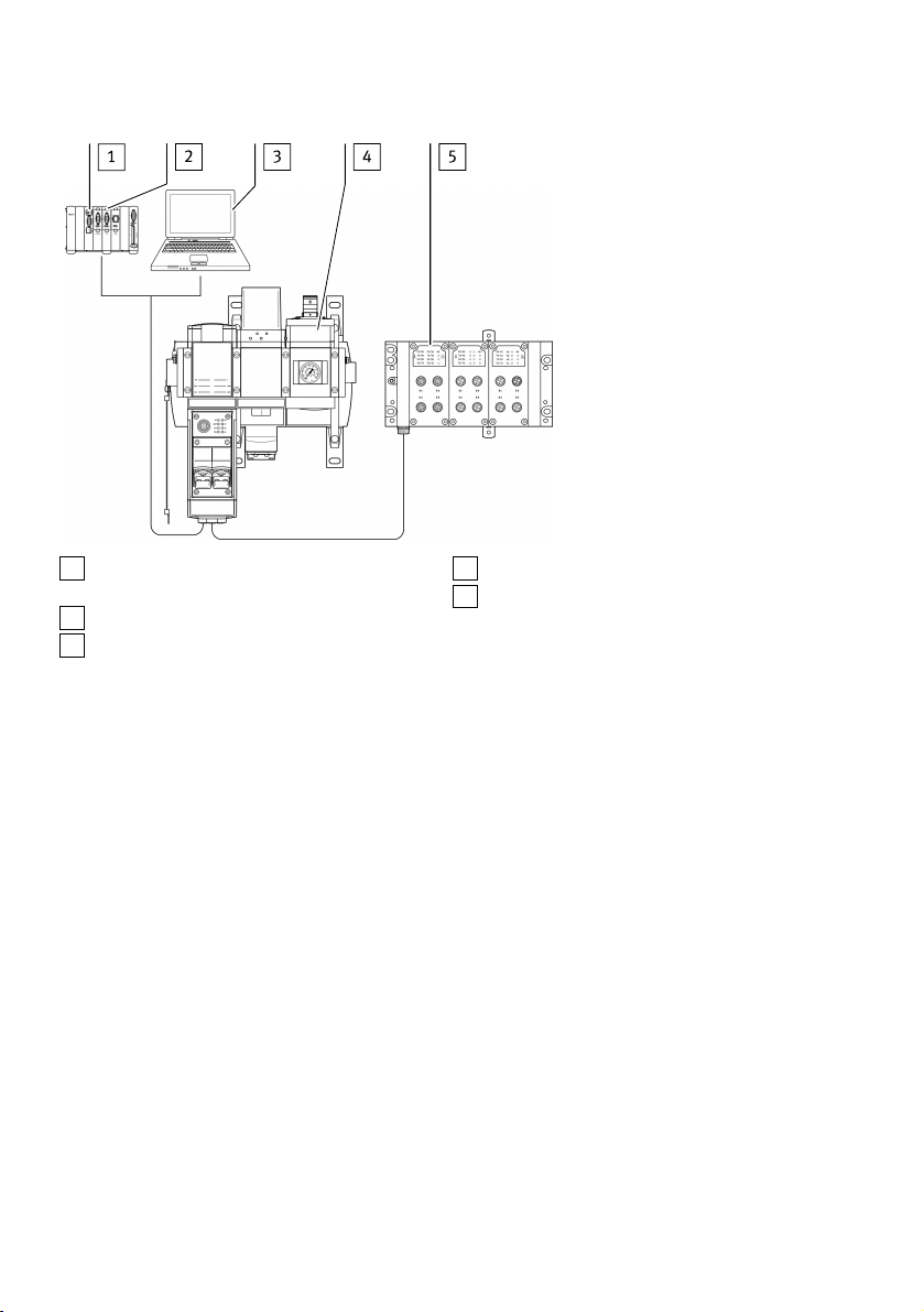
The following illustrations show the communication paths for system configurations with the MSE6-
C2M-...-M and system extensions via CPX-Extension.
12 Festo — MSE6-C2M — 2019-03
Page 13
Product overview
1
Interface module or network-scanner/bus
master
2
User program in the machine controller
3
Network-specific configurator
4
Energy efficiency module MSE6-C2M-...-M
5
Energy efficiency module MSE6-D2M
Fig. 2 System configuration with MSE6-C2M-...-M and MSE6-D2M
13Festo — MSE6-C2M — 2019-03
Page 14
Commissioning
1
Interface module or network-scanner/bus
master
2
User program in the machine controller
3
Network-specific configurator
Fig. 3 System configuration with MSE6-C2M-...-M and 3 CPX I/O modules (maximum configuration)
4
Energy efficiency module MSE6-C2M-...-M
5
CPX I/O modules with CPX-Extension series
2 connection
5.4 Combination with MS6 modules
The product can be extended on the left and right side with service unit components of the MS6
series.
Information on operating and assembly è Instructions for energy efficiency module MSE6-C2M-IN,
www.festo.com/spareparts
6 Commissioning
6.1 Safety
The product is equipped with a pneumatically-piloted proportional-pressure regulator and a downstream shut-off valve. The shut-off valve is pneumatically piloted and is open in a normal position.
When input pressure P1 is applied, the product automatically regulates the outlet pressure in the following cases to the last parameterised power-on target pressure (default setting 10 bar):
– Switch on of operating voltage until the connection is successfully made with the high-order con-
troller.
– Interruption of the network communication with correspondingly set system parameters
– Stopping of the higher-order controller (see manufacturer's specifications), e.g. in the case of
transmission of control programs, parameters, configuration data.
In the basic state, the module regulates the output pressure to the preset Power-On target pressure
when the shut-off valve is open. In the event of undervoltage in the operating voltage or the load
14 Festo — MSE6-C2M — 2019-03
Page 15
Commissioning
voltage, the electronic pressure regulation is inactive when the shut-off valve is open. If prolonged,
this can lead to an undefined drop in the outlet pressure.
6.2 Commissioning the product
In order to avoid connecting and addressing errors, you should carry out the commissioning steps as
follows.
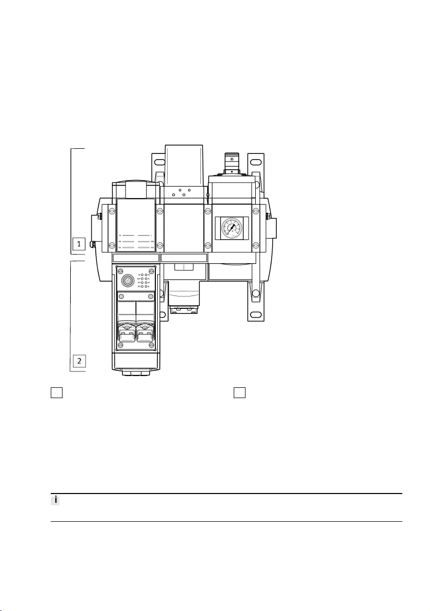
1
Step 1 - Check the connected pneumatic
application
Fig. 4 Commissioning steps
Preparing for commissioning
1. Check pneumatic tubing connection.
2. Check the electrical wiring.
3. Check earth terminal.
4. Check settings of the DIL switches.
The characteristics of the product can be adapted to various requirements.
You can carry out important settings as follows:
– With the DIL switch directly on the bus node
– With parameterisation
2
Step 2 - Commissioning on bus node with
testing of the address allocation
15Festo — MSE6-C2M — 2019-03
Page 16
Commissioning
The product is delivered with pre-set DIL switch and parameters.
Information about DIL èswitches www.festo.com/sp .
6.3 Commissioning with bus node CPX-M-FB34
This section provides a brief overview of the interfaces of the bus node.
Detailed information on the bus ènodes www.festo.com/sp .
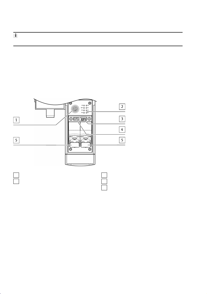
6.3.1 Interfaces and display components
Interfaces and display components on the bus node CPX-M-FB34
1
Service interface
2
Network-specific and CPX-specific LED dis-
plays
Fig. 5 Interfaces and display components on the bus node CPX-M-FB34
16 Festo — MSE6-C2M — 2019-03
3
Memory card (under a cover)
4
DIL switch (under a cover)
5
Network connection (RJ45 bushing)
Page 17
Commissioning
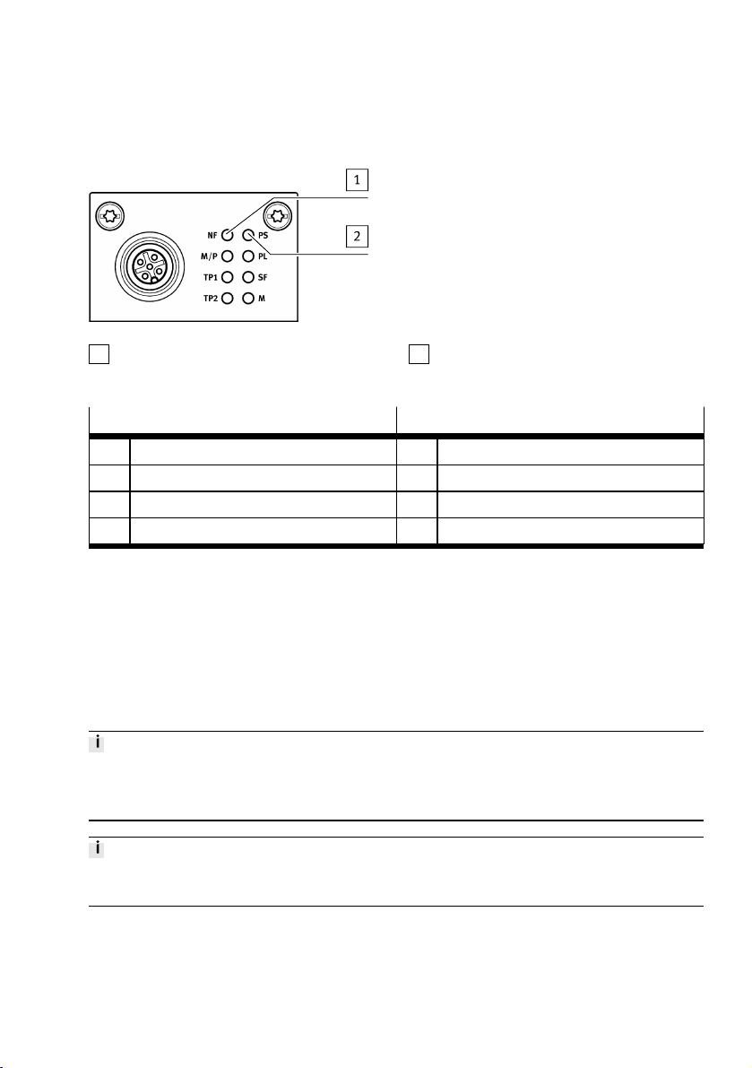
LED displays on the bus node CPX-M-FB34
1
Network-specific LEDs
2
CPX-specific LEDs
Fig. 6 LED display on the bus node CPX-M-FB34
Network-specific LEDs
1)
CPX-specific LEDs
2)
NF Network failure (red) PS Power system (green)
M/P Maintenance/PROFlenergy (green) PL Power load (green)
TP1 Link 1 (green) SF System failure (red)
TP2 Link 2 (green) M Modify (yellow)
1) Without network connection, the LED NF flashes.
2) In normal operating status, all green LEDs light up. The yellow and red LEDs do not light up.
3) parameterisation modified or Force active.
3)
Tab. 7 LED displays
6.3.2 Using the memory card
The memory card is used as a carrier of configuration data for PROFINET addressing and thus simplifies bus node replacement:
– PROFINET I/O device name
– IP address
Inserting or removing the memory card while the power supply is switched on may cause malfunctions
or damage to the memory card.
• Disconnect the power supply before you insert or remove the memory card.
Data stored on the memory card has priority over other configuration data which is stored, e.g. in the
bus node memory or in the higher-order controller.
1. Switch off power supply.
2. Unscrew and remove the retaining screws of the cover.
3. Remove cover.
4. Inserting the memory card.
17Festo — MSE6-C2M — 2019-03
Page 18
Commissioning
5. Fit cover.
6. Tighten the retaining screws of the cover. Tightening torque: 0.4Nm ± 10%.
6.3.3 Network interface
The connection from the bus node to the network is effected with a specific connection technology.
Bus node Connection technology Network connectors
CPX-M-FB34 2x RJ45 bushing, push-pull, AIDA-compli-
Plug connector FBD-RJ45-PP-GS
ant, corresponding to IEC 60603, IEC
61076-3
Tab. 8 Connection technology and network connectors
Seal unused connections with cover caps or blanking plugs to achieve the specified degree of protection.
Network interface on bus node CPX-M-FB34
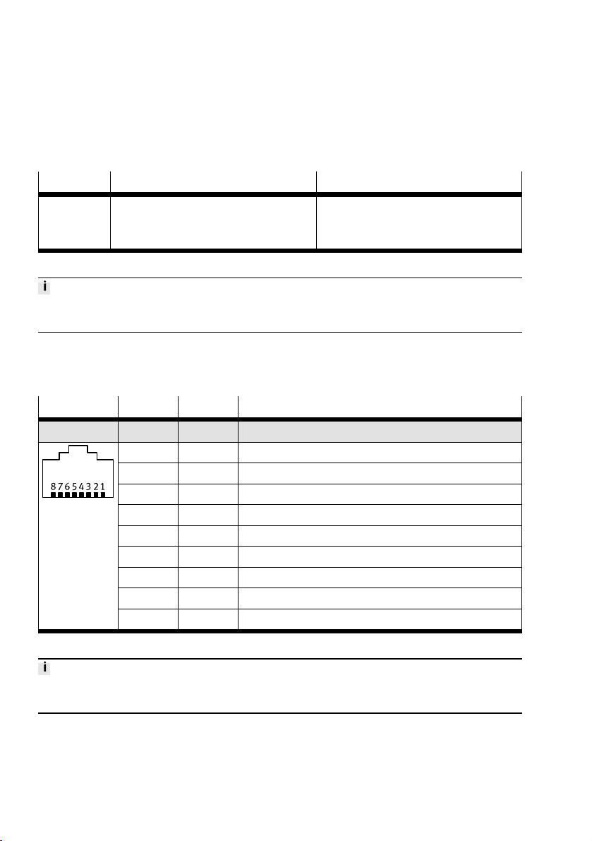
There are two RJ45 push-pull socket bushings (AIDA-compliant) on the bus node CPX-M-FB34 for the
network connection.
RJ45 bushing Pin Signal Explanation
Push-pull
1 TD+ transmit data (transmit data, TD) +
2 TD transmit data –
3 RD+ receive data (receive data, RD) +
4 n.c. Not connected
5 n.c. Not connected
6 RD receive data –
7 n.c. Not connected
8 n.c. Not connected
Housing Shield/FE Shield/functional earth
Tab. 9 Pin allocation of network interfaces on bus node CPX-M-FB34 (RJ45)
Connect the bus node to the network with a Festo plug connector (FBD-RJ45-PP-GS).
The plug connector is designed for Ethernet lines with cable diameters 5…8 mm.
18 Festo — MSE6-C2M — 2019-03
Page 19
Commissioning
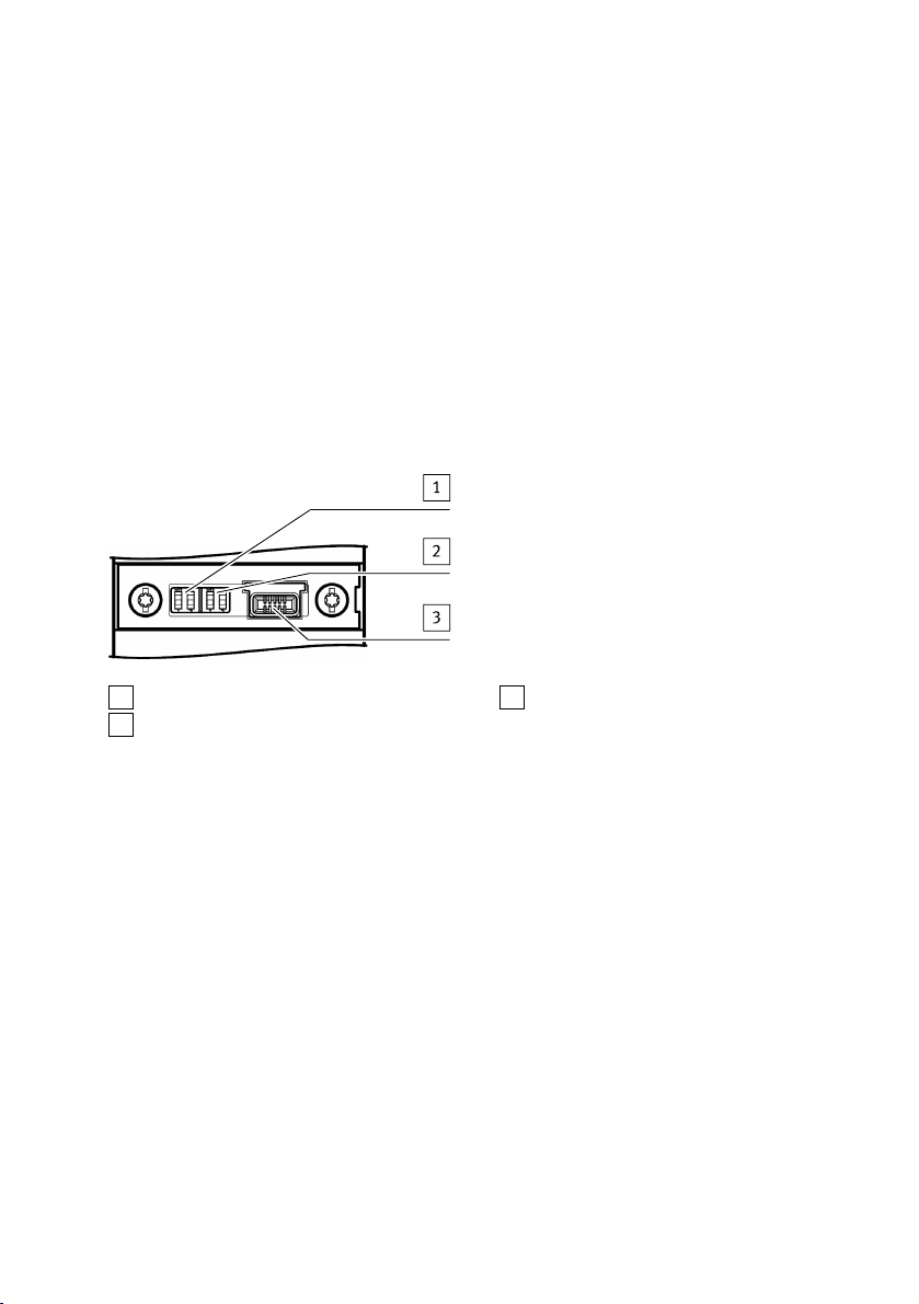
6.3.4 Setting the DIL switches
You can set the following parameters with the DIL switches:
– Operating mode (the MSE6-C2M-…(-M) only supports the Remote I/O operating mode in connec-
tion with the bus node CPX-M-FB34)
– Diagnostics mode
1. Switch off power supply.
2. Unscrew and remove the retaining screws of the cover.
3. Remove cover è2 DIL switches are visible.
4. Use DIL switch1 to set operating mode.
5. Set diagnostic mode using DIL switch2.
6. Fit cover.
7. Tighten the retaining screws of the cover. Tightening torque: 0.4Nm ± 10%.
1
DIL switch 1: operating mode
2
DIL switch 2: diagnostic mode
Fig. 7 DIL switches on bus node CPX-M-FB34
3
Memory card
19Festo — MSE6-C2M — 2019-03
Page 20
Commissioning
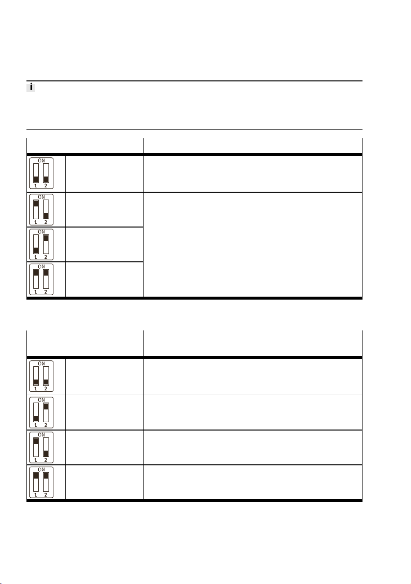
Setting the operating mode (DIL switch 1)
The MSE6-C2M-…(-M) with the bus node CPX-M-FB34 only supports the operating mode Remote I/O
(factory setting).
All switch elements of the DIL switch1 must be in the OFF position.
Setting DIL switch 1 Setting the operating mode
DIL 1.1: OFF
DIL 1.2: OFF
(factory setting)
DIL 1.1: ON
DIL 1.2: OFF
Operating mode: remote I/O
All functions of the MSE6-C2M-…(-M) are controlled directly by
the controller or by a higher-level PLC.
Is not supported by MSE6-C2M-…(-M).
The DIL switch elements 1.1 and 1.2 must be in the OFF position.
DIL 1.1: OFF
DIL 1.2: ON
DIL 1.1: ON
DIL 1.2: ON
Tab. 10 Setting the operating mode with DIL switch 1
Setting the diagnostic mode (DIL switch2)
Setting DIL switch 2 Setting the operating mode
(in the Remote I/O operating mode)
DIL 2.1: OFF
DIL 2.2: OFF
(factory setting)
DIL 2.1: OFF
DIL 2.2: ON
DIL 2.1: ON
DIL 2.2: OFF
I/O diagnostics interface and status bits are switched off or diagnostic mode is set via the hardware configuration of the configuration software1) (+0 Byte E/O byte A)
Status bits are switched on
(+1 byte I/O byte A)
2)
I/O diagnostics interface is switched on
(+2 byte I/2 byte O)
3)
DIL 2.1: ON
Reserved for future extensions
DIL 2.2: ON
1) from Revision 21
2) Status bits occupy 1 byte address space (8 E bits)
3) I/O diagnostics interface occupies 4 bytes of address space (16 I and 16 O bits)
Tab. 11 Setting the diagnostic mode using DIL switch2
20 Festo — MSE6-C2M — 2019-03
Page 21

Commissioning
6.3.5 Commissioning and configuration
Commissioning and configuration of the bus node depend on the higher-order control.
The following steps provide an example for the use of the Siemens SIMATIC S7-315 and the Siemens
STEP 7 controller software (version 5.5 with Service Pack SP 3) with in English. èDocumentation of
higher-level control and control software.
Switching on the power supply
If the control and network participants have separate power supplies, the devices must be switched in
the following sequence:
1. Switch on the power supply of the MSE6-C2M-…(-M).
2. Switch on the power supply for the controller.
Addressing the network
The controller uses the following for addressing:
– Device names
– IP addresses (optional MAC-ID)
– Input and output addresses (I/O addresses)
Basic addressing rules
Bus node:
– The bus node occupies 0 inputs and 0 outputs if no diagnostic message is active.
– Active status bits occupy 8 input bits.
– 1 active I/O diagnostic interface occupies 16 input and 16 output bits.
Network:
– The address assignment of the inputs does not depend on the address assignment of the outputs.
– Addressing is carried out in bytes
Device description file (GSDML file)
A device description file (GSDML file) is needed for configuration and parameterisation of the bus
node. The device description file contains all information required to integrate the module into the
higher-order controller.
Device description file èwww.festo.com/sp.
Setting up automation project and controller
1. Start the controller software.
Create a new project: [File] > [New…].
2.
3. Enter a project name, e.g. MSE6-C2M, PROFINET.
Insert control used: [Insert] >[Station, e.g. SIMATIC 300 Station].
4.
5. Extend project tree and select controller.
Open the hardware configuration window: [Edit] > [Open Object].
6.
Installing the device description file
1. Open the Festo Support Portal èwww.festo.com/sp.
2. Enter search term "GSDML MSE".
3. Select, save and unpack the current device description file in the Software tab.
21Festo — MSE6-C2M — 2019-03
Page 22

Commissioning
Install the device description file: [Options] > [Install GSD File...]. Select the file path of the device
4.
description file: [Browse]. Select and install the file: [Install].
Update hardware catalogue: [Options] > [Update Catalog].
5.
èAll available CPX modules appear in the hardware catalogue under:
\PROFINET IO\Additional Field Devices\Valves\Festo MSE Air Supply
Setting up automation project and controller
Open hardware catalogue: [View] > [Catalog].
1.
2. Extend control in hardware catalogue (e.g. SIMATIC300) and folder structure.
3. Expand folder RACK-300.
4. Insert profile rail in controller.
5. Reproduce the controller configuration using the components from the rack rail table in the hardware catalogue.
Row 1 (Slot 1) is reserved, e.g. for a fixed power supply.
Creating a PROFIBUS network
1. Open Properties… dialogue. Right-click on the interface, e.g. X2 and [Object Properties].
2. Switch to the “General” tab.
3. Open the dialogue "Properties Ethernet…": Click on the button "Properties".
4. Creating a new network: click on the button "New" and adjust specific settings.
5. Right-click on interface, e.g. X2 and [Insert PROFINET IO System].
Insert PROFINET station ("Station")
• Drag the status symbol MSE6-C2M-5000-FB34 from the hardware catalogue onto the bus line of
the PROFINET-IO system.
\PROFINET-IO\Additional Field Devices\Valves\Festo MSE Air Supply
– MSE6-C2M-5000-FB34
Assigning a "Device Name"
Assign device names: [PLC] > [Ethernet] > [Assign Device Name].
1.
2. Search participant: click on the button "Update".
3. Select device. Click the Assign name button.
Transmitting hardware configuration
• Translate hardware configuration and transmit it to controller.
22 Festo — MSE6-C2M — 2019-03
Page 23
Measuring and control function
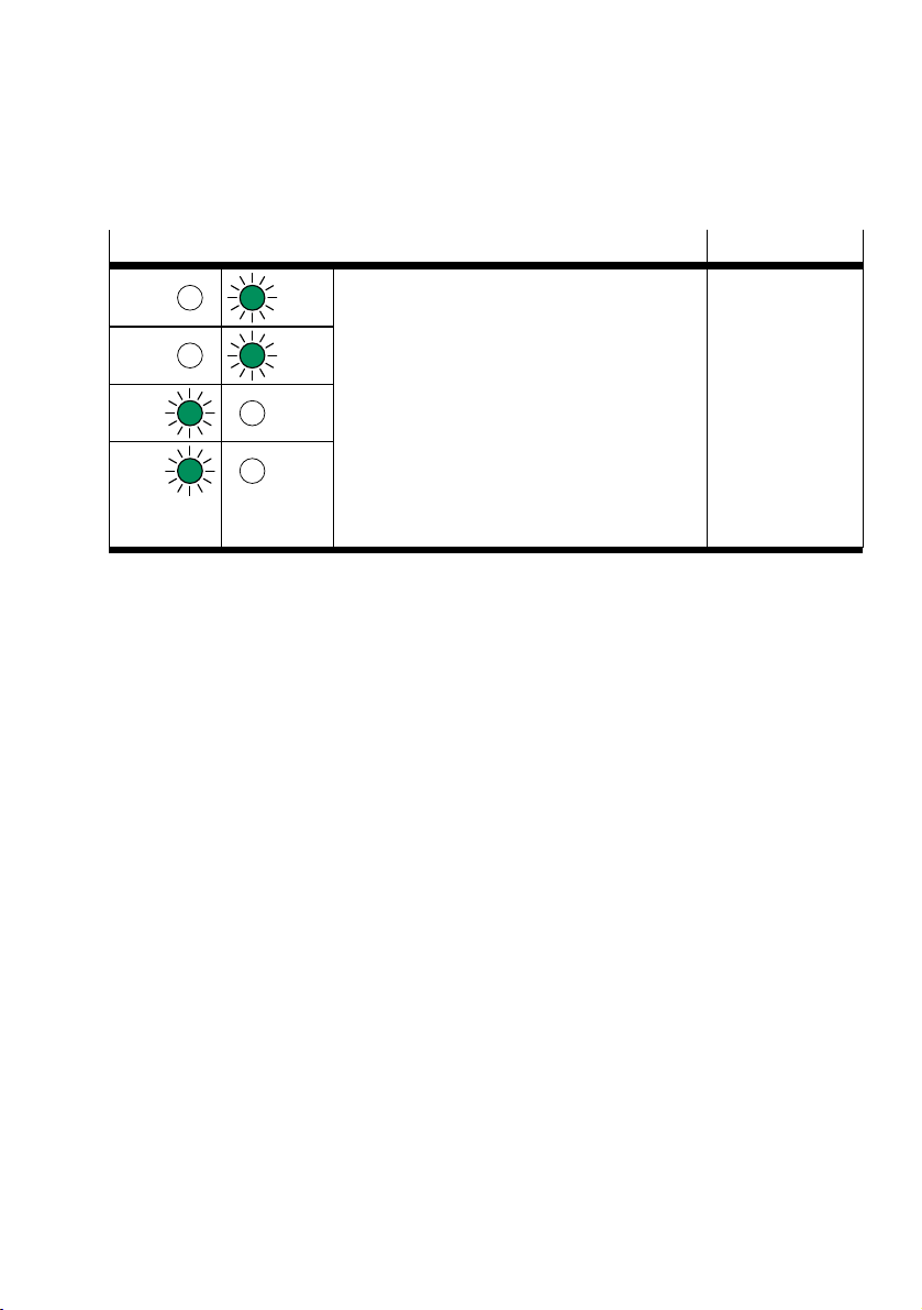
6.3.6 Faultless commissioning, normal operating status
After faultless commissioning, specific LED displays on the bus node light up. The other LEDs are for
diagnostics and error handling è 10 Diagnostics.
LED displays Operating status
NF PS
The following LEDs light green:
Normal, no error
– PS
M/P PL
TP1 SF
– PL
1)
– TP1
1)
– TP2
The following LEDs do not light:
– NF
TP2 M
– M/P
– SF
The "M" LED lights or flashes if parameterisation
is changed or Force is active.
1) Only if port used: continuous light (network connection OK).
Tab. 12 Normal operating status of the MSE6-C2M-…(-M) with bus node CPX-M-FB34
7 Measuring and control function
The following sections provide an overview of the individual measurement and control functions of the
product and present their setting options and their influencing variables.
Individual functions and their behaviour can be controlled using the outputs and/or parameters.
Measurement and status signals are available as input values. Diagnostic information is made available as a combination of the error number and their respective channel allocation.
For the following designations of inputs and outputs and parameters, m is the module number that is
based on the address position of the product in the CPX overall system and has the fixed value m=0.
7.1 Flow rate
Input signal
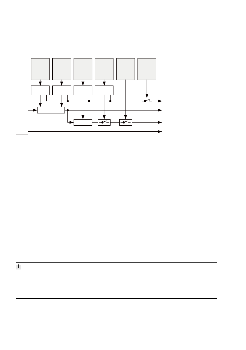
The measured flow rate is prepared according to the set parameters flow rate (Pm.8.2-8.3) and "Unit
flow rate" (Pm.8.6-8.7) and “Unit flow rate standard” and provided as an input signal (Em.0).
Critical limit monitoring
A comparator is used to compare the measured flow rate value with the parameter “Upper critical limit
flow rate” (Pm.11-12). When the time set in the parameter "Monitor critical limits" startup (Pm.7) has
elapsed and critical limit monitoring is activated (Pm.0.6), the appropriate error/diagnostic message is
output if a critical limit is exceeded.
Monitoring of parameters
The parameters flow rate (Pm.8.2-8.3), flow standard (Pm.8.6-8.7), upper limit flow (Pm.11-12) and
monitoring critical limit startup(Pm.7) are checked for permissible values when entered. In case of
error, the appropriate error message is output if parameterisation error monitoring is activated
(Pm.0.7).
23Festo — MSE6-C2M — 2019-03
Page 24
Unit
flow rate
Pm.8.2-8.3
Flow rate
standard
Pm.8.6-8.7
Upper
critical limit
flow rate
Pm.11-12
Monitoring
of
critical limit
startup
Pm.7
Monitoring
of
critical limits
Pm.0.6
Monitoring
of
parameter
Pm.0.7
Data
check
Scaling
Flow
rate
sensor
sensor
error
Data
check
Data
check
Data
check
Comparator
Diagnostics, maskable
FN25, Em.0: parameterisation error upp. critical limit
FN29, Em.0: error in parameterisation
Input
Em.0: flow rate
Diagnostics, maskable
FN10, Em.0: upp. critical limit exceeded
Diagnostics, not maskable
FN15, Em.0: sensor defective
Flow rate
Measuring and control function
Sensor monitoring
If there is a sensor error, the appropriate error message, which cannot be deactivated, is output.
Fig. 8 Block diagram of the "Flow rate" function
7.2 Consumption
Input signals
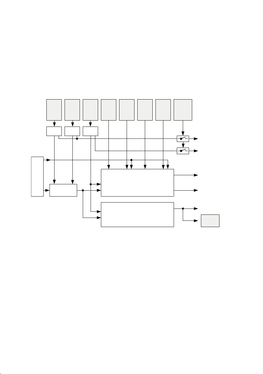
The consumption measurement is based on the prepared flow rate value. Depending on the unit consumption (Pm.8.4-8.5) and flow standard (Pm.8.6-8.7) parameters, the consumption values are processed in 2 independent channels and provided as input signals in 16-bit and 32-bit data format:
– Consumption V0 (16 bit): input Em.1 and selectable inputs Em.5 and/or Em.6
– Consumption V0 (32 bit): selectable inputs Em.5-6
– Consumption V1 (16 Bit): selectable inputs Em.5 and/or Em.6
– Consumption V1 (32 bit): selectable inputs Em.5-6
There is also a continuous consumption measurement which, after a certain, unit-dependent consumption, generates a logic 1 measurement impulse with a duration of 100ms. For the consumption
units l and m³, the consumption value is 200l. For the consumption unit scf, the consumption value is
10scf.
The measuring pulse is provided at the input Measuring pulse consumption VC (Em.3.7). In addition,
the signal is output at electrical output 0 if the parameter Select DO0 signal has the value
Pm.28.3=1.
If there is a change to the parameter values “Unit flow rate” or “Flow rate standard”, the measured
consumption values are reset to the value “0”.
If there is a change to the parameter value “Unit consumption”, the current measured consumption
values are saved and converted to the new consumption unit.
User-controlled consumption measurement
2-channel consumption measurement is controlled using two data bits in the output word for module
control (Am.0). With the outputs Consumption V0 Run (Am.0.12) or Consumption V1 Run (Am.0.14),
24 Festo — MSE6-C2M — 2019-03
Page 25
Unit
flow rate
Pm.8.2-8.3
Flow rate
standard
Pm.8.6-8.7
Unit
consumption
Pm.8.4-8.5
Consumption
V0
Run
Am.0.12
Monitoring
of
parameter
Pm.0.7
Data check
Scaling
Data check Data check
Diagnostics, maskable
FN29, Em.0:
error in parameterisation
Inputs
Em.1: consumption V0 (16 Bit)
Em.3.12: status measurement consumption 0
Em.3.13: status measurement consumption 1
Consumption
Consumption
V0
Reset
Am.0.13
Consumption
V1
Run
Am.0.14
Consumption
V1
Reset
Am.0.15
Reset
consumption
V0
User-controlled
consumption measurement
V0 and V1
Run / Stop
consumption
V0
Run / Stop
consumption
V1
Reset
consumption
V1
Selectable inputs
Em.5-6: consumption V0 (16/ 32 bit)
consumption V1 (16/ 32 bit)
Diagnostics, maskable
FN29, Em.1:
error in parameterisation
Continuous
consumption measurement
VC
Consumption
measurement
impulse
Input:
Em.3.7: measurement impulse consumption VC
Electrical
output
VC
Sensor
error
flow
rate
sensor
Measuring and control function
the respective consumption measurement is started, continued or stopped. Via the outputs Consumption V0 Reset (Am.0.13) or Consumption V1 Reset (Am.0.15), the respective consumption measurement values can be reset to the value 0.
Monitoring of parameters
The parameters “Unit flow rate”, (Pm.8.2-8.3), “Unit flow rate standard” (Pm.8.6-8.7) and “Unit
consumption” (Pm.8.4-8.5) are checked on entry for permitted values. In the event of an error, the corresponding error message is output if parameterisation error monitoring is activated (Pm.0.7).
Fig. 9 Block diagram of the “Consumption” function
7.3 Pressure
Input signal
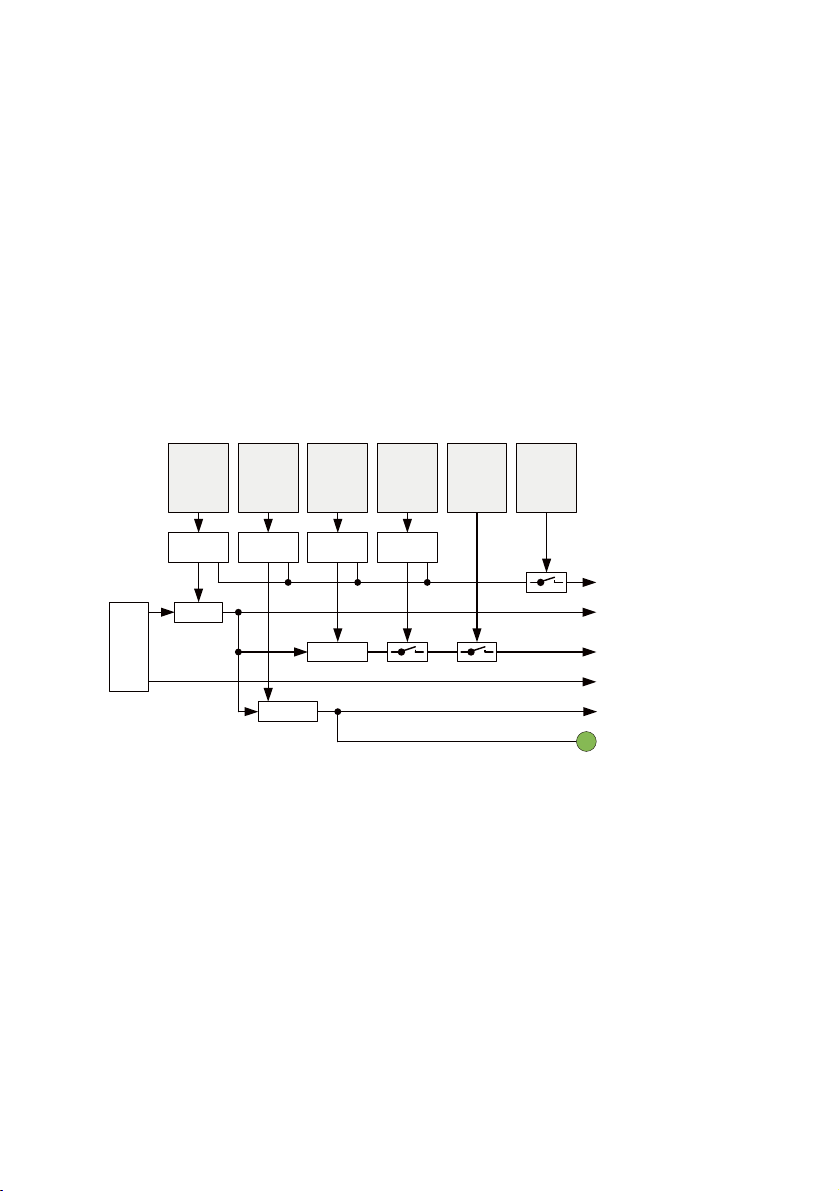
The measured value output pressure P2 is prepared according to the parameter “Unit pressure”
(Pm.8.0-8.1) and made available as an input signal pressure P2 (Em.2).
Monitoring of lower pressure critical limit P2 and status indicator
A comparator is used to compare the measured pressure value with the parameter “Lower pressure
critical limit” P2. The result is indicated in two ways.
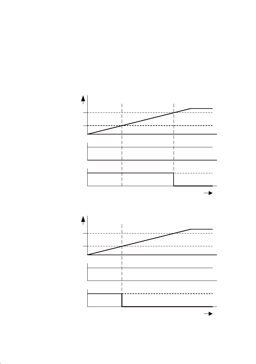
• Status LED P2
LED lights up: outlet pressure P2 ³ lower critical limit pressure P2
–
LED flashes: outlet pressure P2 < lower critical limit pressure P2 and
–
Outlet pressure p2 ³ pressure setpoint auto standby - 0.5bar
Condition not applicable if:
Lower critical limit pressure P2 < Pressure setpoint Auto Standby - 0.5bar
LED not illuminated: outlet pressure P2 < pressure setpoint auto standby - 0.5bar
–
25Festo — MSE6-C2M — 2019-03
Page 26
Em.2:
pressure P2
Pm.25-26:
lower critical limit pressure P2
Status LED P2
LED P2 not
illuminated
t
LED P2 illuminated
1
Em.3.6:
monitoring of
lower critical limit pressure
P2
0
Pm.23-24 – 0.5 bar:
pressure setpoint auto standby
– 0.5 bar
LED P2 flashes
Em.2:
pressure P2
Pm.25-26:
lower critical limit pressure P2
Status LED P2
LED P2 not
illuminated
t
LED P2 illuminated
1
Em.3.6:
monitoring of
lower critical limit pressure P2
0
Pm.23-24 – 0.5 bar:
pressure setpoint
auto standby – 0.5 bar
Measuring and control function
• Input monitoring "Lower pressure critical limit" P2 (Em.3.6)
Logic 1: outlet pressure P2 < lower critical limit pressure P2
–
Logic 0: outlet pressure P2 ³ lower critical limit pressure P2
–
The figures show the behaviour of the status LED P2 and the input signal Monitoring of lower critical
limit pressure P2 for the two parameterisation cases:
Case 1: Lower critical limit pressure P2 > pressure setpoint Auto Standby - 0.5bar
–
Case 2: Lower critical limit pressure P2 <pressure setpoint Auto Standby - 0.5bar
–
Fig. 10 Monitoring of lower pressure critical limit P2 and status indicator (case 1)
Fig. 11 Monitoring of lower pressure critical limit P2 and status indicator (case 2)
26 Festo — MSE6-C2M — 2019-03
Page 27
Unit
pressure
Pm.8.0-8.1
Upper
critical limit
pressure
Pm.13-14
Monitoring
of
critical limit
startup
Pm.7
Monitoring
of
critical limits
Pm.0.6
Monitoring
of
parameter
Pm.0.7
Data
check
Data
check
Data
check
Comparator
Diagnostics, maskable
FN24, Em.2: parameterisation error low. critical limit
FN25, Em.2: parameterisation error upp. critical limit
FN29, Em.2: error in parameterisation
Input
Em.2: pressure P2
Diagnostics, maskable
FN10, Em.2: upp. critical limit exceeded
Diagnostics, not maskable
FN15, Em.2: sensor defective
Pressure P2
(MSE6-D2M)
Scaling
Status LED P2
Lower
critical limit
pressure
P2
Pm.25-26
Comparator
Data
check
Input
Em.3.6: status monitoring P2_UGR
P2
pressure
sensor
sensor
error
Measuring and control function
Monitoring of upper pressure critical limit
A comparator is used to compare the measured pressure value with the parameter “Upper pressure
critical limit” (Pm.13-14). When the time set in the parameter "Monitor critical limits" startup (Pm.7)
has elapsed and critical limit monitoring is activated (Pm.0.6), the appropriate error/diagnostic message is output if a critical limit is exceeded.
Monitoring of parameters
The parameters unit pressure (Pm.8.0-8.1), lower critical limit pressure P2 (Pm.25-26), upper critical
limit pressure (Pm.13-14) and monitoring critical limit startup (Pm.0.7) are checked for permissible
values during input. In the event of an error, the corresponding error message is output if parameterisation error monitoring is activated (Pm.0.7).
Sensor monitoring
If there is a sensor error, the appropriate error message, which cannot be deactivated, is output.
Fig. 12 Block diagram of the “Pressure” function
7.4 Pressure change
7.4.1 Method of measurement
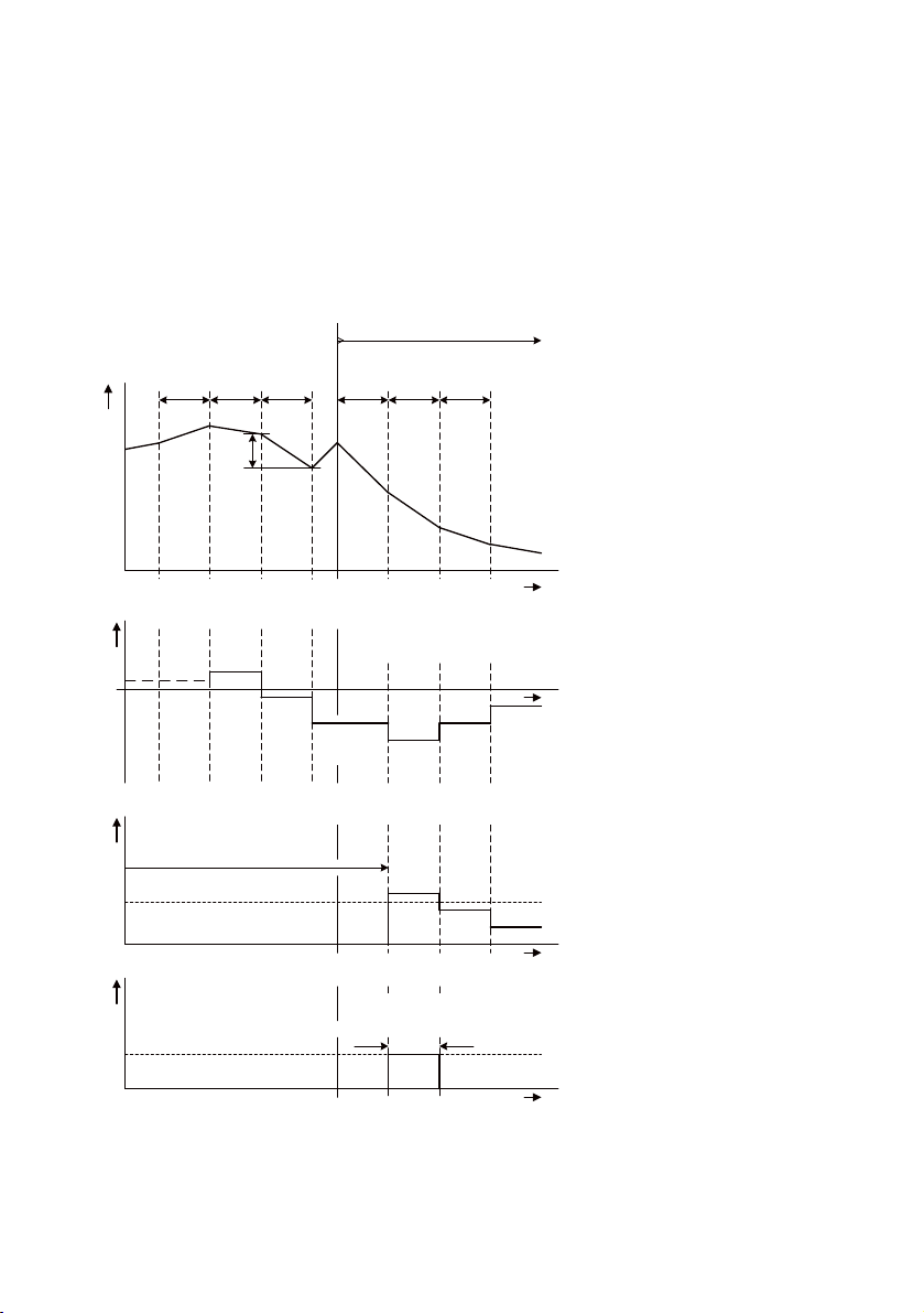
The pressure change DP2 is determined cyclically at intervals of the parameterisable pressure change
sample time DT. When calculating the pressure change, the difference between the current measured
pressure value and the measured pressure value DT, based on the pressure change sample time P2, is
calculated:
DP2=P2(t)–P2(t-DT); t=current measurement time.
The start of the measuring cycle to calculate the pressure change is automatically synchronised with
the activation signal of the shut-off valve. The current pressure change value DP2 remains constant up
to the next measuring time. Each time the parameter "Unit" (Pm.8) is written, a re-synchronisation follows.
27Festo — MSE6-C2M — 2019-03
Page 28
Pressure
P2
DT
t
0
DT DT DT DT DT
DP2
t
1
t
2
t3t
4
t
5
t
6
t
7
t
Blocking
DT synchronisation on
switching on the shut-off valve at t = t
4
0
Pressure
change
DP2
DP2 =
P2(t
1
)
- P2(t
0
)
DP2 =
P2(t
2
)
- P2(t
1
)
DP2 =
P2(t
3
) - P2(t2)
DP2 =
P2(t
5
)
- P2(t
4
)
DP2 =
P2(t
6
)
- P2(t
5
)
t
DP2 =
P2(t
7
)
- P2(t
6
)
DP2 signal extension
for DT synchronisation from t = t
4
DP2_OGR
Amount
of
pressure
change:
ABS(DP2)
t
No ABS(DP2) calculation
Diagnostics
message
t
Upper critical limit
exceeded:
ABS(DP2) > DP2_OGR
Message
active
Measuring and control function
In the blocking state, the amount of the pressure change value is compared to the upper pressure
change critical limit DP2_OGR and monitored to determine whether the critical limit has been
exceeded. Once critical limit monitoring is activated, a diagnostic message is generated if the parameter ABS(DP2) is > DP2_OGR.
DT synchronisation and DP2 OGR critical limit monitoring
The time diagrams show the DT synchronisation and DP2 OGR critical limit monitoring.
Fig. 13 DT synchronisation and DP2 OGR critical limit monitoring
28 Festo — MSE6-C2M — 2019-03
Page 29
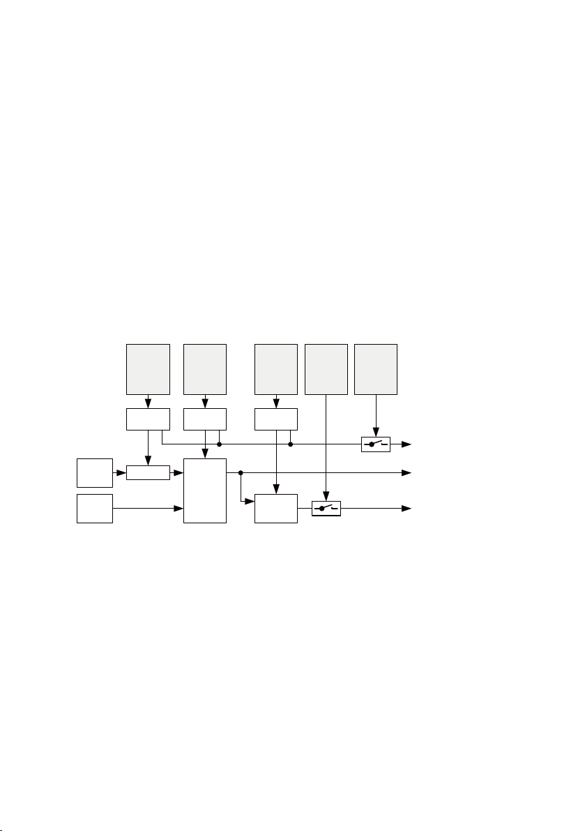
Unit
pressure
Pm.8.0-8.1
Upper
critical limit
pressure
change
Pm.15-16
Pressure
change
measurement
time
Pm.10
Monitoring
of
critical limits
Pm.0.6
Monitoring
of
parameter
Pm.0.7
Data
check
P2
pressure
sensor
Data
check
Data
check
Comparator
Diagnostics, maskable
FN25, Em.3: parameterisation error upp. critical limit
FN29, Em.2: error in parameterisation
FN29, Em.3: error in parameterisation
Selectable inputs
Em.5 / 6: pressure change DP2
Diagnostics, maskable
FN10, Em.3: upp. critical limit exceeded
Pressure change DP2
Scaling
Em.3.0:
status
shut-off
valve
Measurement
pressure
change
Measuring and control function
7.4.2 Function structure
Input signal
The measured pressure change value DP2 is prepared according to the set parameters “Unit pressure”
(Pm.8.0-8.1) and “Pressure change sample time” (Pm.10) and can be shown as a selectable input signal in Em.5 and/or Em.6.
Critical limit monitoring
If the shut-off valve is in the blocking state, the amount of the measured pressure change is compared
with the parameter “Upper critical limit pressure change”(Pm.15-16) using a comparator. If critical
limit monitoring is activated (Pm.0.6), the appropriate error/diagnostic message is output if the critical limit is exceeded.
Monitoring of parameters
The parameters “Unit Pressure” (Pm.8.0-8.1), “Pressure change sample time” (Pm.0) and “Upper limit
pressure change” (Pm.15-16) are checked on entry for permitted values. In the event of an error, the
corresponding error message is output if parameterisation error monitoring is activated (Pm.0.7).
Fig. 14 Block diagram of the “Pressure change” function
7.5 Pressure regulation and blocking function
7.5.1 Overview
The pressure regulation and blocking function function determines the current module status by evaluating pressure and flow measured values. The desired outlet pressure P2 is set by controlling the
pressure regulator and the shut-off valve accordingly.
Depending on the setting, the module works in user-controlled or automatic pressure regulation and
blocking function.
In the user-controlled pressure regulation and blocking function, the shut-off valve is controlled directly. One of the various fixed values or a variable value can be set as the target pressure.
29Festo — MSE6-C2M — 2019-03
Page 30

Measuring and control function
In automatic pressure regulation and blocking function, the target pressure is set to Auto Normal in
the basic state. If the flow rate falls below the set flow rate critical limit for the specified period of time,
the automatic pressure regulation and blocking function first switches to shut-off mode if activated
accordingly. After a pressure drop to the target pressure Auto Standby, the function then switches to
pressure regulation mode with the target pressure Auto Standby.
In this state, a corresponding control signal is required to change to pressure regulation mode with
the target pressure Auto Normal. Depending on the selection, this control signal must be generated by
an output control bit or one of the two electrical inputs.
Status and status signals of the pressure regulation and blocking function are displayed in an input
word for user-side sequence monitoring.
In both user-controlled and automatic pressure regulation and blocking function, there is a moduleinternal target pressure value limitation to a range between 2.5…and 10 bar and a parameterisable
target pressure rise limitation.
The entire structure of the pressure regulation and blocking function with all sub-functions, operands
(inputs, outputs, parameters) and error/diagnostic messages is described in the subchapter Function
Structure.
7.5.2 User-controlled pressure regulation and blocking function (USER)
The user-controlled pressure regulation and blocking function is activated if the output control AutoUser (Am.0.1) has the value 0 (not active).
In this state, the shut-off valve can then be switched by the user to the status "Pressurise" or "Block"
with the output Controller Shut-off valve (Am.0.0). The switching status of the shut-off valve is signalled in input Em.3.0.
For the target pressure for the pressure regulating valve, the target pressure user selection
(Am.0.3-0.4) output can be used to select between the following values and functions:
– Power-On target pressure, adjustable to 10 bar or 6 bar with the parameter Power-On target pres-
sure (Pm.28.2)
– Minimum target pressure (2.5 bar)
– Deactivated electronic pressure regulation
– Variable target pressure setting via output target pressure user (Am.2)
With Power-On and any further user-side increase in the target pressure value, the rise slope is limited
to the value set with the target pressure rise limitation parameter (Pm.28.4-28.6).
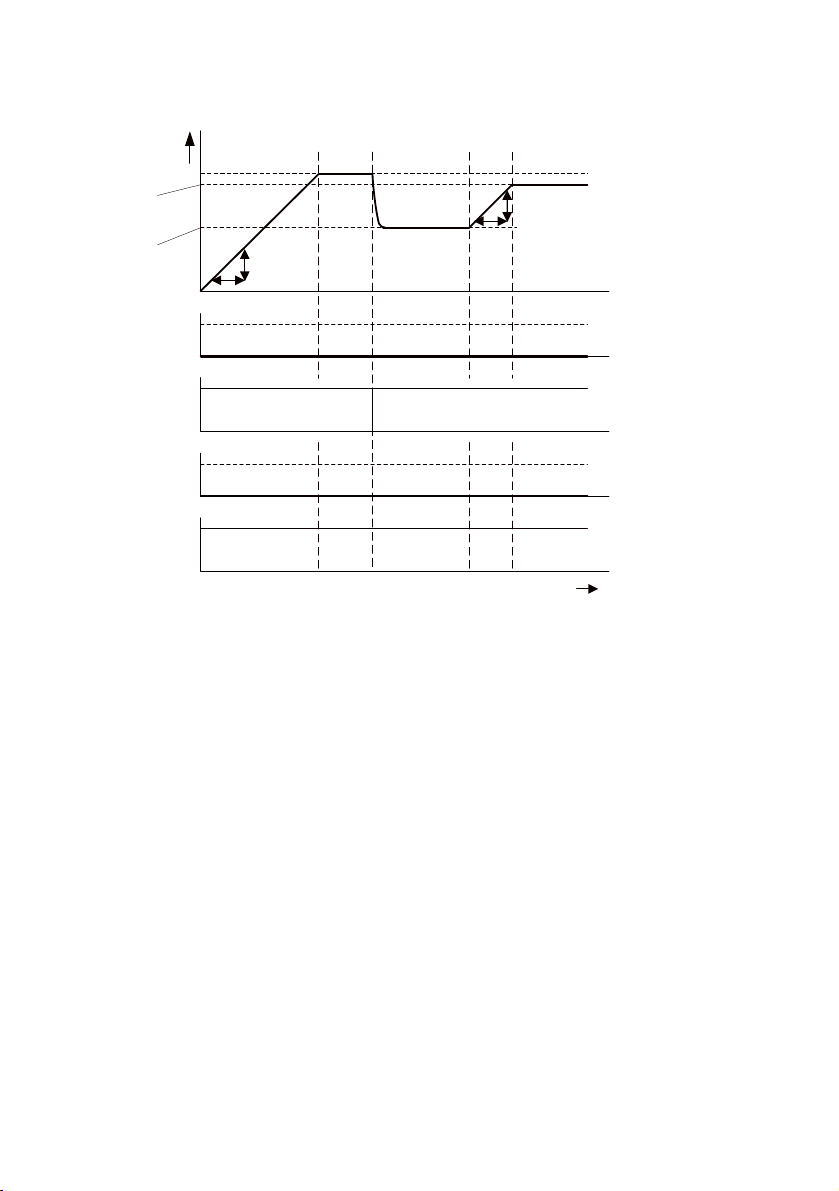
The time diagram shows the module behaviour after Power-On and subsequent variable target pressure adjustment to 2 different values.
30 Festo — MSE6-C2M — 2019-03
Page 31
Em.2:
pressure P2
Em.3.8-3.11:
module status
0:
USER_
RISE
1:
USER_
PON
Am.0.3-0.4:
target
pressure
user selection
t
Am.0.1:
control of
auto user
Auto = 1
User = 0
4:
USER_
VAR
Am.2:
target pressure user
2nd value
Pm.28.4-28.6:
target
pressure
rise
limitation
Pm.28.2:
target
pressure
power on
0:
Power on
target pressure
6 bar = 1
10 bar = 0
10 bar
Pm.28.4-28.6:
target
pressure
rise
limitation
Am.2:
target pressure user
1st value
0:
USER_
RISE
4:
USER_
VAR
3:
target pressure
user variable
Measuring and control function
Fig. 15 User-controlled pressure regulation and blocking function
7.5.3 Automatic pressure regulation and blocking function (AUTO)
The automatic pressure regulation and blocking function is activated when the output control AutoUser (Am.0.1) has the value 1 (active).
The automatic pressure regulation and blocking function starts with each activation in module state
AUTO_NORMAL (Em.3.8-3.11 =8). In this state, the shut-off valve is open and the pressure regulating
valve regulates to the parameter value Target pressure Auto Normal (Pm.21-22). At the same time, the
Q_low-Timerfunction starts monitoring to check whether the flow rate value falls below the parameter
value Auto-controller flow rate critical limit (Pm.19-20). If the value falls below the critical limit, a
change to the state AUTO_WAIT(Em.3.8-3.11 =9) takes place and the duration of the state is monitored by the Q_low-Timer. If the critical limit underrun exceeds the time limit set with the parameter
Auto-controller delay time (Q_low-Timer has elapsed), a change to the state AUTO_HOLDoccurs
(Em.3.8-3.11 =10). In this state, if the shut-off valve is still open, the setpoint pressure is set to Auto
Normal. If the flow rate reaches or exceeds the Auto-controller flow rate critical limit during the states
AUTO_NORMAL, AUTO_WAITandAUTO_HOLD, the flow rate immediately returns to the state
AUTO_NORMAL(Em.3.8-3.11 =8).
To switch the target pressure from Auto Normal to Auto Standby in the stateAUTO_HOLD, the output
control Auto-Enable (Am.0.5 =1) must be activated. This can be done permanently or by the user
depending on the system, e.g. if automatic switching is not permitted due to the situation.
31Festo — MSE6-C2M — 2019-03
Page 32

Measuring and control function
If Auto-Enable is activated (Am.0.5 =1) in the output control stateAUTO_HOLD, the shut-off valve
switches to the shut-off state and the new module state is AUTO_SHUTOFF(Em.3.8-3.11 =11). As
soon as the pressure P2 has dropped to the target pressure Auto Standby, the module status changes
to AUTO_STANDBY(Em.3.8-3.11 =12). The shut-off valve is open again and the pressure regulating
valve regulates to the target pressure Auto Standby.
A change from the module state AUTO_STANDBYwith target pressure Auto Standby to the module
state AUTO_NORMAL with target pressure Auto Normal is only possible by resetting the Q_low-Timers.
While the pressure increases, the function is in module AUTO_RISEstate (Em.3.8-3.11 =13). In this
state, the slope of the pressure rise is limited to the value set with the target pressure rise limitation
parameter (Pm.28.4-28.6).
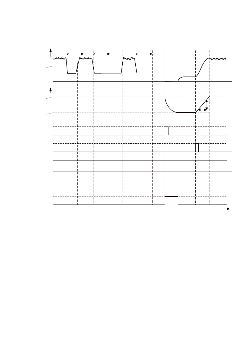
The following figure gives an overview of the relevant measurement, control and status signals of the
automatic pressure regulation and blocking function by means of an exemplary flow rate curve. The
output Q_low-Timer-Reset(Am.0.2) is set as the signal source for resetting theQ_low-Timers.
32 Festo — MSE6-C2M — 2019-03
Page 33
Em.0:
flow rate
Pm.19-20:
Auto
control of
flow rate
critical limits
Em.2:
pressure P2
Pm.17-18:
auto control of
time delay
Em.3.8-3.11:
module status
8:
AUTO_
NORMAL
9:
AUTO_
WAIT
8:
AUTO_
NORMAL
9:
AUTO_
WAIT
11:
AUTO_
SHUTOFF
13:
AUTO_
RISE
Em.3.4-3.5:
status of
Q_low timer
0:
RES
0:
RES
1:
RUN
2:
UP
1:
RUN
0:
RES
Em.3.0:
status
shut-off valve
Am.0.2:
Q_LOW
timer reset
t
Am.0.5:
control of
auto enable
10:
AUTO_
HOLD
2:
UP
Shutoff
= 1
0
1
0
1
0
Pm.17-18:
auto control of
time delay
8:
AUTO_
NORMAL
9:
AUTO_
WAIT
Pm.17-18:
auto control of
time delay
10:
AUTO_
HOLD
0:
RES1:RUN2:UP
Pm.21-22:
pressure set
point
auto normal
Pm.23-24:
pressure
setpoint
auto standby
12:
AUTO_
STANDBY
8:
AUTO_
NORMAL
Pm.28.4-28.6:
target pressure
rise
limitation
2:
UP
0:
RES
Measuring and control function
Fig. 16 Automatic pressure regulation and blocking function
33Festo — MSE6-C2M — 2019-03
Page 34

Measuring and control function
7.5.4 Functional states
The current functional state is displayed in the input module state (Em.3.6-3.9).
The table shows an overview of the possible functional states in all operating modes.
Em.3.8-3.11
Module
Functional
status
Functional
mode
Meaning
Status
0 USER_RISE USER Pressure increase until the target pressure set by
the user is reached
1 USER_PON USER Pressure regulation to set Power-On target pres-
sure
2 USER_MIN USER Pressure regulation to minimum target pressure
(2.5 bar)
3 USER_REGOFF USER Electronic pressure regulation is deactivated
4 USER_VAR USER Pressure regulation to set target pressure accord-
ing to Am.2
5 USER_SHUTOFF USER_ Module in shut-off mode
7 OFF_24VA USER/AUTO No load power supply
Pressure regulation and blocking function not active
8 AUTO_NORMAL AUTO Pressure regulation at parameterised target pres-
sure Auto Normal
9 AUTO_WAIT AUTO Pressure regulation at parameterised target pres-
sure Auto Normal, Q_low-Timerexpired, automatic
pressure regulation and blocking function not activated
10 AUTO_HOLD AUTO Pressure regulation at parameterised target pres-
sure Auto Normal, Q_low-Timerexpired, automatic
pressure regulation and blocking function not activated
11 AUTO_SHUTOFF AUTO Module in shut-off mode, Q_low-Timer expired,
automatic pressure regulation and blocking function activated
12 AUTO_STANDBY AUTO Pressure regulation at parameterised target pres-
sure Auto Standby
13 AUTO_RISE AUTO Pressure increase up to the parameterised target
pressure Auto Normal
Tab. 13 Possible functional states in all operating modes
34 Festo — MSE6-C2M — 2019-03
Page 35
Unit
flow
rate
Pm.8.2
-8.3
Flow
rate
standard
Pm.8.6
-8.7
Auto
control of
flow rate
critical
limit
Pm.19
-20
Auto
control of
delay
time
Pm.17
-18
Moni-
toring of
Uaus/
Uven
Pm.0.2
Scaling
Compa-
rator
FN29, Am.0:
parameterisation
error
Em.3.4-3.5:
status of
Q_low_timer
Pressure
regulation and
blocking
function
Flow
rate
Q_low
timer
FN26, Am.0:
undervoltage
actuator
supply
Q_low
timer
reset
Am.0.2
FN29,
Em.0, Em.2:
paramaterisation
error
Target
pressure
user
selection
Am.0.3
-0.4
Target
pressure
user
Am.2
Target
pressure
rise
limitation
Pm.28.4
-28.6
Moni-
toring of
parameter
Pm.0.7
Auto
control of
shutoff valve
and
auto
target
pressure
calculation
Pressure regulator
DI0
Em.3.2
DI1
Em.3.3
OR
Q_low-
timer
reset
selection
Pm.28.0
-28.1
Monitoring of
actuator
supply
Module status
Em.3.8-3.11:
module
status
Pressure
Unit
pressure
Pm.8.0
-8.1
Data
check
Pressure
setpoint
auto
normal
Pm.21
-22
Target
pressure
value
auto
standby
Pm.23
-24
FN29, Am.1:
parameterisation
error
Target
pressure
rise
limitation
Shut-off
valve
Em.3.0:
status of
shutoff valve
Pm.31-32:
switching cycles of
shutoff valve
Control of
shut-off
valve
Am.0.0
Control of
auto
user
Am.0.1
Numerator
Target
pressure
power-
on
Pm.28.2
Target
pressure
value
limitation
2.5...10 bar
Control
of
auto
enable
Am.0.5
Reset
10 bar
Data
check
Data
check
Data
check
Data
check
Data
check
Scaling
2.5 bar
6 bar
OFF
1 0
Measuring and control function
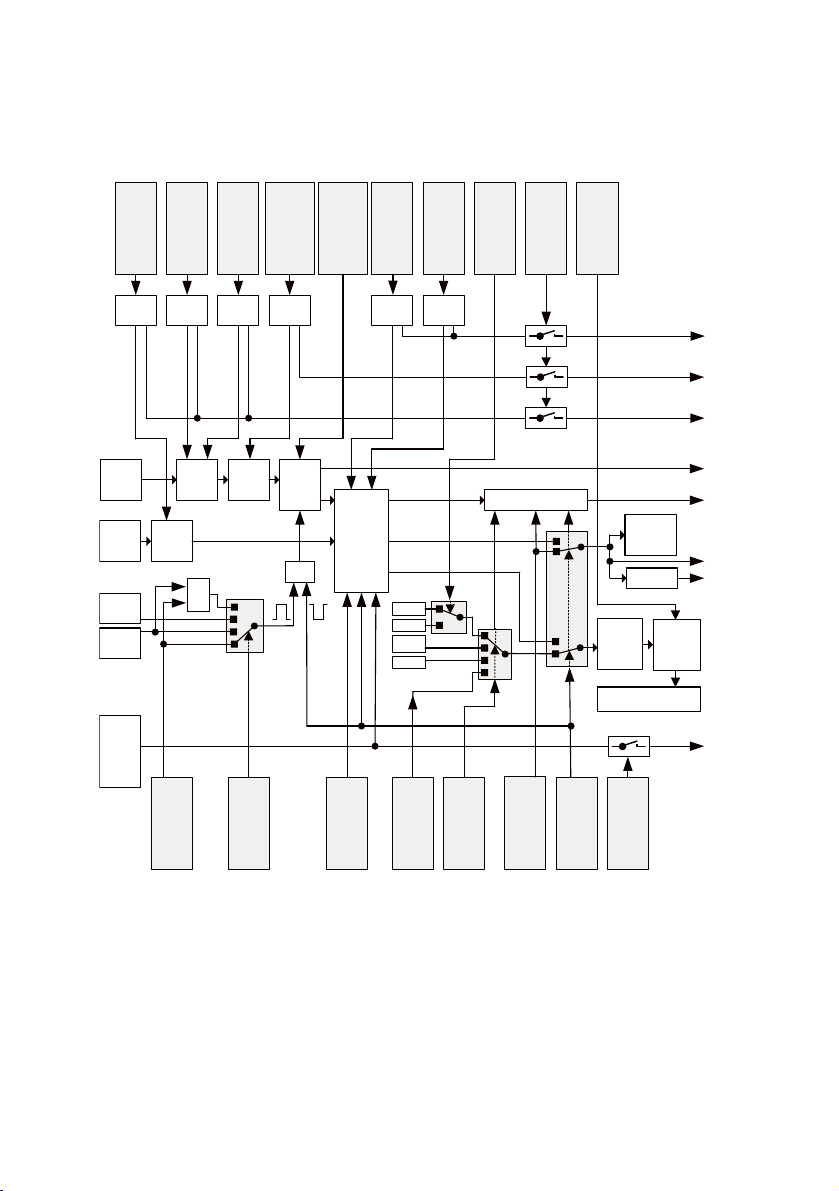
7.5.5 Function structure
Fig. 17 Block diagram of the pressure regulation and blocking function
Q_low-Timer
The function Q_low-Timer continuously compares the prepared measured flow rate value with the
parameter Auto-controller flow rate critical limit. If the critical limits are not reached, Q_low-Timer is
started. The Q_low-Timer enters status UP if the flow rate critical limit is not reached for longer than
the time parameterised in the parameter Auto-controller delay time (Pm.17-18).
The timer status is displayed in the input status Q_low-Timer (Em.3.4-3.5) and can have the following
values:
– 0=RES: the timer is reset and not started.
35Festo — MSE6-C2M — 2019-03
Page 36

Measuring and control function
– 1=RUN: the timer was started and is running.
The timer has not yet exceeded the parameter value Auto-controller delay time (Pm.17-18).
– 2=UP: the Timer has expired.
The timer has exceeded the parameter value Auto-controller delay time (Pm.17-18).
The Q_low-Timer is reset in the following cases:
– In module state AUTO_WAIT(Em.3.8-11=9) and
In module state AUTO_HOLD(Em.3.8-11=10) when Auto-controller flow rate critical limit is
exceeded (Pm.19-20)
– by a reset control signal (1=active). The signal can be selected with the parameter Q_low-Timer-
Reset selection (Pm.28.0-28.1):
– Output Q_low-Timer-Reset (Am.0.2)
– Electrical input DI0
– Electrical input DI1
– Logic operation: electrical input DI0 OR output Q_low-Timer-Reset(Am.0.2)
Module status
The module status results from the status or status of sub-functions of the pressure regulation and
blocking function and is displayed in input (Em.3.8-3.11).
The individual module states are described in chapter Function states.
Shut-off valve
Depending on the setting of output control Auto-User (Am.0.1), the shut-off valve is controlled either
by the user or by the partial function Auto-controller shut-off valve.
The switching status of the shut-off valve is determined by the input Status shut-off valve (Em.3.0):
The shut-off valve switching cycle number is provided in different types and data formats:
– 16-bit or 32-bit input value via selectable inputs Em.5 and/or Em.6
– 16 bit parameter value (Pm.31-32)
Pressure regulator
Depending on the setting of output control Auto-User (Am.0.1), the target pressure for the pressure
regulator is determined as follows:
– By the target pressure value set by the user
– By the target pressure value specified by the Auto target pressure sub-function.
Before being passed on to the pressure regulator, the setpoint value is limited to values between 2.5
and…10.0bar within the module. The rise is limited to the set parameter value when the target pressure is increased.
Monitoring of parameters
The parameters "Pressure unit" (Pm.8.0-8.1), "Flow rate unit" (Pm.8.2-8.3), "Flow rate standard"
(Pm.8.6-8.7), "Auto-controller flow rate critical limit" (Pm.19-20) are checked for permissible values
when entered. In case of error, the appropriate error message is generated if parameterisation error
monitoring is activated (Pm0.7).
Actuator supply monitoring
This function is used to monitor the actuator supply for undervoltage. In the event of an error, the corresponding error message is generated with activated monitoring (Pm.0.2).
36 Festo — MSE6-C2M — 2019-03
Page 37
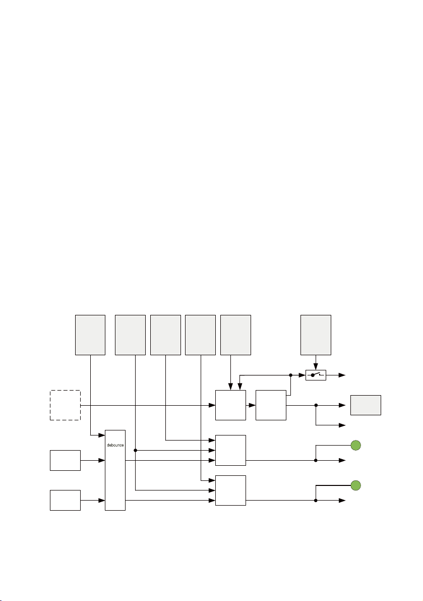
Electrical inputs
Monitoring of
short circuit /
overload
sensor
supply
Pm.0.0
Diagnostics, maskable
FN2, Em.3
error in undervoltage
sensor supply
System supply
24VES
Behaviour
after
short circuit /
overload
sensor supply
Pm.27.6
Signal
generation
sensor
supply
24VSEN
Short circuit /
overload
protection
24VSEN
Sensor supply
24VSEN
Diagnostics KS/Ü
Electrical
input 1
Electrical
input 0
Signal
DI0,
DI1,
Signal
debounce
time
Pm.27.4-27.5
Signal
extension
channel
DI1
Pm.27.1
Signal
extension
time
Pm.27.2-27.3
Signal
extension
DI0
Input Em.3.2:
Electr. input DI0
Signal
extension
DI1
Input Em.3.3:
Electr. input DI1
Status LED DI1
Status LED DI0
Signal
extension
channel
DI0
Pm.27.0
Input Em.3.1:
monitoring of sensor
supply
Measuring and control function
7.6 Electrical inputs
The "Electrical inputs" function is equipped with 2 digital inputs, which can also be used to reset the
Q_low-Timers of the pressure regulation and blocking functions with appropriate parameterisation.
Input signals
The signals of the electrical inputs 0 and 1 are processed according to the parameters debounce time
DI (Pm.27.4-27.5) and signal extension time DI (Pm.27.2-27.3). The times are valid for both channels.
The activation of the signal extension is set channel by channel with the parameters Signal extension
channel DI0 (Pm.27.0) and Signal extension channel DI1 (Pm.27.1). The input signals are provided as
electrical input DI0 (Em.3.2) and electrical input DI1 (Em.3.3).
Status indicators
The status of the electrical inputs is indicated channel by channel by status LEDs. When the LED is lit,
a logic 1 is present at the input, when the LED is not lit, a logic 0.
Sensor supply
The sensor supply voltage 24VSEN is provided at the connections for the electrical inputs. The sensor
supply voltage 24VSEN is internally protected against short-circuit/overload. The parameter Behaviour after short-circuit/overload sensor supply (Pm.27.6) is used to set whether the sensor supply is
switched on again after short-circuit/overload end or remains switched off. If the diagnosis with the
parameter Monitoring short-circuit/overload sensor supply (Pm.0.0) is activated, the corresponding
error message is generated in case of overload.
m=module number (0)
Fig. 18 Block diagram, electrical inputs
37Festo — MSE6-C2M — 2019-03
Page 38

Measuring and control function
7.7 Electrical outputs
The electrical outputs function is equipped with 2 digital outputs, one of which can be used alternatively for the output of the consumption measurement pulse.
Output signals
The electrical outputs are controlled via the outputs module control Am.0.6 and Am.0.7 during basic
setting. Alternatively, the consumption measurement pulse VC can be output at output DO0 if the DO0
Signal Selection (Pm.28.3) parameter is set accordingly.
The electrical outputs have an internal short-circuit/overload protection. The parameter Behaviour
after short-circuit/overload outputs (Pm.27.7) defines whether the electrical outputs remain switched
off after short-circuit/overload end or are switched on again automatically.
Status indicators
The status of the electrical outputs is displayed channel by channel by means of a status LED. When
the LED is lit, the output provides a logic 1. If the LED is not lit, the output provides a logic 0.
Monitoring of short circuit/overload
The electrical outputs are monitored channel by channel for short-circuit/overload. The error status is
signalled in input module status (Em.3.14 for output 0, Em.3.15 for output 1). In addition, with activated diagnostics (setting with parameter Pm.0.1), a group error message is generated for outputs 0
and 1 if at least 1 channel is overloaded.
Actuator supply monitoring
The actuator supply is monitored for undervoltage. In the event of an error, the corresponding error
message is generated with activated monitoring (Pm.0.2).
38 Festo — MSE6-C2M — 2019-03
Page 39
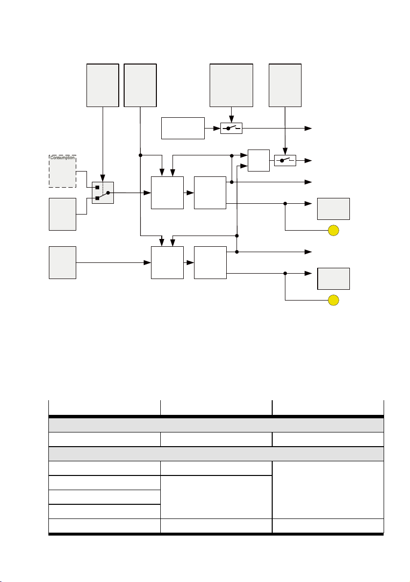
OR
Signal
generation
DO0
Diagnostics, maskable
FN2, Am.0:
short circuit/overload error
Electr. outputs
Input
Em.3.14: short circuit/overload
output 0
Electrical
outputs
Electrical
output
DO0
Am.0.6
Electrical
output
DO1
Am.0.7
Behaviour
after
short circuit /
overload
el. outputs
Pm.27.7
Monit-
oring of
short circuit /
overload
el. outputs
Pm.0.1
Short circuit /
overload
protection
Diagnostics KS/Ü DO0
Electrical
output
0
Input
Em.3.15: short circuit/ overload
output 1
Short circuit /
overload
protection
Diagnostics KS/Ü DO1
Electrical
output
1
Signal
generation
DO1
Monitoring of
undervoltage
actuator supply
24VA
Pm.0.2
Monitoring of
actuator supply
24VA
Diagnostics, maskable
FN26, Am.0:
error in undervoltage
actuator supply
Status LED DO0
Status LED DO1
Selection
DO0
signal
Pm.28.3
Measure-
ment
impulse
VC
Input/output data
Fig. 19 Block diagram, electrical outputs
8 Input/output data
The product possesses multiple items of functional module data, which can be replaced with the higher-order controller using the I/O data presented below.
8.1 Overview
Data field / function Input
Flow measurement
1)
Measured value Em.0
Consumption measurement
Measured value V0 (16bit) Em.1
Measured value V0 (32bit)
Measured value V1 (16bit)
Measured value V1 (32bit)
Measurement impulse VC Em.3.7
Data access via selectable input
data: Em.5, Em.6
2)
Output
–
Input address for data selection: Am.1
–
39Festo — MSE6-C2M — 2019-03
Page 40
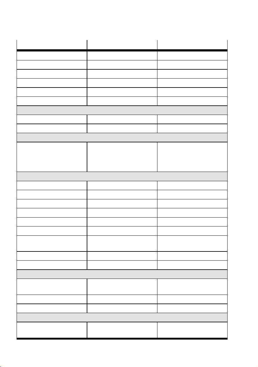
Input/output data
Data field / function Input
1)
Status V0 Em.3.12
Status V1 Em.3.13
Consumption V0 Run
Consumption V0 Reset
Consumption V1 Run
Consumption V1 Reset
–
–
–
–
Pressure measurement
Measured value Em.2
Monitoring of lower critical limit Em.3.6
Pressure change measurement
Measured value Data access via selectable input
data: Em.5, Em.6
è 8.3 Selectable input data
function.
Pressure regulation and blocking function
Status of shut-off valve Em.3.0
Status Q_low-Timer Em.3.4-3.5
Module status Em.3.8-3.11
Shut-off valve controller
Auto-user controller
Q_low-Timer-Reset
Selection of user target pres-
–
–
–
–
sure
Auto enable controller
User pressure setpoint
–
–
Electrical inputs
Monitoring
Em.3.1
Sensor supply
Status of electrical input 0 Em.3.2
Status of electrical input 1 Em.3.3
Electrical outputs
Monitoring
Em.3.14
Electrical output 0
Output
–
–
Am.0.12
Am.0.13
Am.0.14
Am.0.15
–
–
Input address for data selection: Am.1
è 8.3 Selectable input data
function.
–
–
–
Am.0.0
Am.0.1
Am.0.2
Am.0.3-0.4
Am.0.5
Am.2
–
–
–
–
40 Festo — MSE6-C2M — 2019-03
Page 41
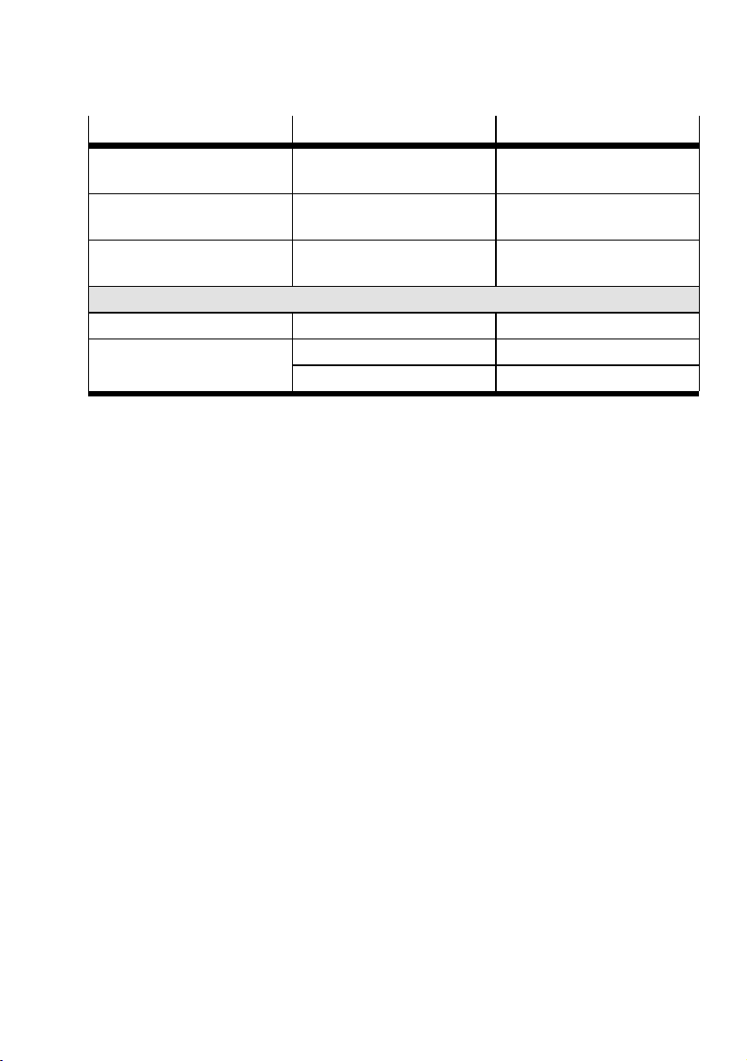
Input/output data
Data field / function Input
Monitoring
1)
Em.3.15
Output
–
Electrical output 1
Control
–
Am.0.6
Electrical output 0
Control
–
Am.0.7
Electrical output 1
Selectable input data
Input address Em.4 Am.1
Input data
Em.5 (data bits 0…15)
Em.6 (data bits 16…32)
1) m=Module number (0)
2) Data access also possible via selectable input data.
–
–
Tab. 14 Overview of I/O data
8.2 Description of I/O data
• The input and output words of all I/O data are shown in Motorola format (MSB-LSB).
• The output words (2 byte, 16 bit) are transferred to the higher-order controller.
• The output words (2 byte, 16 bit) are transmitted from the higher-order controller.
41Festo — MSE6-C2M — 2019-03
Page 42

Input/output data
8.2.1 Output word Am.0 "Module control" [Modul control]
Output word Am.0 is used to control the pressure regulation and blocking function as well as the consumption measurement.
Data format of output word “16 bits, right-justified”
D15 D14 D13 D12 D11 D10 D9 D8 D7 D6 D5 D4 D3 D2 D1 D0
B15 B14 B13 B12
– – – –
B7 B6 B5 B4 B3 B2 B1 B0
MSB LSB
Abbreviations used
B0 Shut-off valve controller
B1 Auto-user controller
B2 Q_low-Timer-Reset
B3, B4 Selection of user target pressure
B5 Auto enable controller
B6 Electrical controller output 0
B7 Electrical controller output 1
B12 Consumption V0 Run
B13 Consumption V0 Reset
B14 Consumption V1 Run
B15 Consumption V1 Reset
––
Reserved data bits
D0…D15 16bit output data field
MSB/LSB Most significant bit /least significant bit
Tab. 15 Data format of output word Am.0
Output data, pressure regulation and blocking function
Data bit B0 has the following values:
– 0=open shut-off valve - (pressurisation state, default)
– 1=closed shut-off valve (blocking state)
Data bit B1 has the following values:
– 0=operating mode "User-controlled pressure regulation and blocking function" active (default)
– 1=operating mode "Automatic pressure regulation and blocking function" active
Data bit B2 has the following values:
– 0=no change in status of the Q_low-Timers (default)
– 1=Resetting the Q_low-Timers
42 Festo — MSE6-C2M — 2019-03
Page 43

Input/output data
Data bits B3 and B4 have the following values:
– 0=user-controlled target pressure=Power-On target pressure (depending on Pm.28.2, default)
– 1=user-controlled target pressure=2.5bar
– 2=electronic pressure regulation not active
– 3=user-controlled target pressure=target pressure user variable (Am.2)
Data bit B5 has the following values:
– 0=automatic pressure regulation and blocking function not active (default)
– 1=automatic pressure regulation and blocking function active
The control signal can be used for a user-controlled or permanent activation of the automatic pressure
regulation and blocking function.
Output data, electrical outputs
Data bit B6 has the following values:
– 0=electrical output 0 sends logic 0 (default)
– 1=electrical output 0 sends logic 1
Data bit B7 has the following values:
– 0=electrical output 1 sends logic 0 (default)
– 1=electrical output 1 sends logic 1
Consumption measurement output data
Data bits B12 and B14 have the following values:
– 0=measurement not active: measurement is stopped (default)
– 1=measurement active: measurement is started or continued
Data bits B13 and B15 have the following values:
– 0=reset function not active (default)
– 1=reset function active: measured consumption value is reset to value 0
8.2.2 Output word Am.1 "Input address" [Input address]
The output wordAm .1 belongs to the function Selectable input data and is described in the chapter of
the same name.
43Festo — MSE6-C2M — 2019-03
Page 44
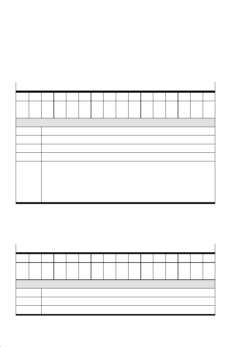
Input/output data
8.2.3 Output word Am.2 "Pressure setpoint P2" [Set point pressure P2]
Setting target pressure P2
– In the operating mode "User-controlled pressure regulation and blocking function" (Am.0.1)
– With output word P2
– With user-controlled target pressure (Am.0.3=3)
– In the currently valid pressure unit (Pm.8.0-8.1)
Data format of output word "sign+15 bits, right-justified"
D15 D14 D13 D12 D11 D10 D9 D8 D7 D6 D5 D4 D3 D2 D1 D0
VZ B14 B13 B12 B11 B10 B9 B8 B7 B6 B5 B4 B3 B2 B1 B0
MSB LSB
Abbreviations used
VZ Sign (for data format sign+15 bits always =0, i.e. positive value)
B0…B14 Pressure setpoint P2
D0…D15 16bit output data field
MSB/LSB Most significant bit /least significant bit
Remarks: Pressure setpoints are automatically limited within the permissible value range
(0…32767) to the end values of the nominal pressure range within the module,
depending on the parameterised pressure unit and without an error message:
– mbar: 2500…10000
– kPa: 250…1000
– psi/10: 363…1450
Tab. 16 Data format of output word Am.2
8.2.4 Input word Em.0 "Flow rate" [Flow]
In the input word Em.0, the flow rate value is displayed in accordance with the parameterised flow rate
unit and flow rate standard. The presetting of the module parameter “Unit flow rate” is “l/min”, the
presetting of the module parameter “Flow rate standard” is “DIN 1343”.
Data format of input word “Sign + 15 bits, right-justified”
D15 D14 D13 D12 D11 D10 D9 D8 D7 D6 D5 D4 D3 D2 D1 D0
VZ B14 B13 B12 B11 B10 B9 B8 B7 B6 B5 B4 B3 B2 B1 B0
MSB LSB
Abbreviations used
VZ Sign (for data format Sign+15 bits always =0, i.e. positive value)
B0…B14 Flow rate value
D0…D15 16-bit input data field
44 Festo — MSE6-C2M — 2019-03
Page 45
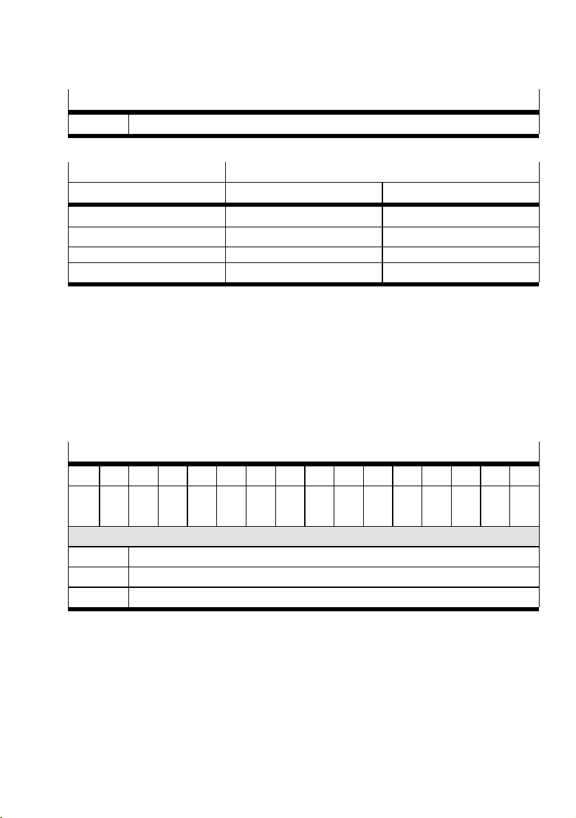
Input/output data
Data format of input word “Sign + 15 bits, right-justified”
MSB/LSB Most significant bit /least significant bit
Tab. 17 Data format of input word Em.0 "Flow rate"
Flow rate Input value
[l/min] [l/min] [scfm/10]
0 0 0
50 50 18
… … …
5000 5000 1766
Tab. 18 Unit-dependent flow rate values
8.2.5 Input word Em.1 "Consumption" [Consumption]
In the input word Em.1, the consumption value V0 (16 bit) is displayed in accordance with the parameterised consumption unit and flow rate standard and limited to max. 65535 (16-bit value) independently of the parameterised unit. Via selectable input data, the measurement value is also available as a 32-bit value. The presetting of the module parameter “Unit consumption” is l, the presetting
of the module parameter “Unit flow rate standard” is “DIN 1343”. If there is a change to the flow rate
unit and/or flow rate standard, the consumption is reset to the value “0”. If there is a change to the
consumption unit, the consumption value remains unchanged and is converted correspondingly.
Data format of input word “16 bits, right-justified”
D15 D14 D13 D12 D11 D10 D9 D8 D7 D6 D5 D4 D3 D2 D1 D0
B15 B14 B13 B12 B11 B10 B9 B8 B7 B6 B5 B4 B3 B2 B1 B0
MSB LSB
Abbreviations used
B0…B15 Consumption value
D0…D15 16-bit input data field
MSB/LSB Most significant bit /least significant bit
Tab. 19 Data format of input word Em.1 "Consumption"
45Festo — MSE6-C2M — 2019-03
Page 46
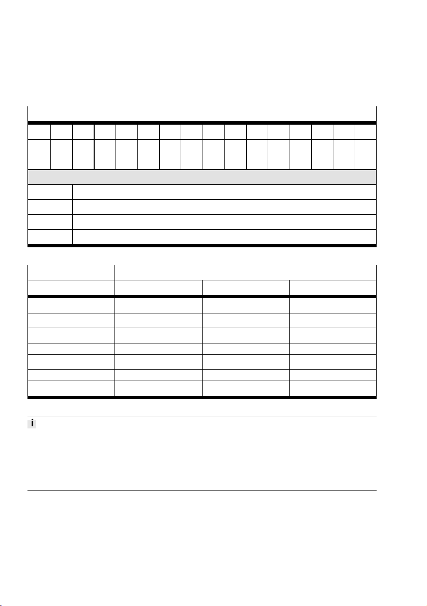
Input/output data
8.2.6 Input word Em.2 "Pressure P2" [Pressure P2]
In the input word Em.2, the pressure value P2 is displayed in accordance with the parameterised pressure unit. The presetting of the module parameter “Unit pressure” is “mbar”.
Data format of input word “Sign+15 bits, right-justified”
D15 D14 D13 D12 D11 D10 D9 D8 D7 D6 D5 D4 D3 D2 D1 D0
VZ B14 B13 B12 B11 B10 B9 B8 B7 B6 B5 B4 B3 B2 B1 B0
MSB LSB
Abbreviations used
VZ Sign (for data format “Sign+15bits” always = 0, i.e. a positive value)
B0…B14 Pressure value P2
DO…D15 16-bit input data field
MSB/LSB Most significant bit /least significant bit
Tab. 20 Data format of input word Em.2 "Pressure P2"
Pressure P2 Input value
[bar] [mbar] [kPa] [psi/10]
0 0 0 0
1 1000 100 145
4 4000 400 580
… … … …
7.36 7360 736 1067
… … … …
14 14000 1400 2030
Tab. 21 Unit-dependent pressure values
The pressure measurement data is presented according to the unit and is rounded off.
Measured value resolution:
• mbar: 20
• kPa: 2
• psi/10: 5
8.2.7 Input word “Pressure change DP2"
The value of the pressure change can only be displayed via selectable input data as a signed 16-bit
value in the input words Em.5 and/or Em.6 in accordance with the parameterised pressure unit and
pressure change measurement time.
46 Festo — MSE6-C2M — 2019-03
Page 47
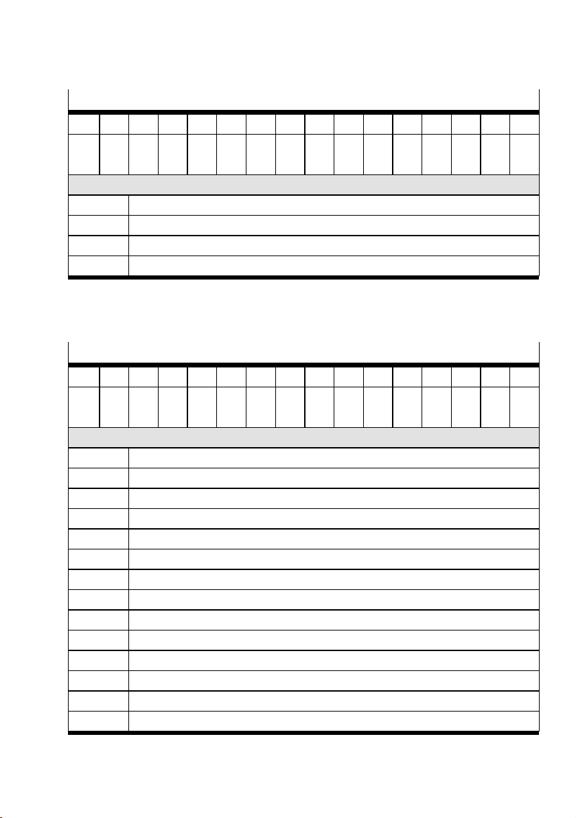
Input/output data
Data format of input word “Sign+15 bits, right-justified”
D15 D14 D13 D12 D11 D10 D9 D8 D7 D6 D5 D4 D3 D2 D1 D0
VZ B14 B13 B12 B11 B10 B9 B8 B7 B6 B5 B4 B3 B2 B1 B0
MSB LSB
Abbreviations used
VZ Sign
B0…B14 Pressure change value
DO…D15 16-bit input data field
MSB/LSB Most significant bit /least significant bit
Tab. 22 Data format of input word Em.5/Em.6 “Pressure change”
8.2.8 Input word Em.3 “Module status” [Status]
In the input word Em.3, status information on the module is displayed.
Data format of input word “16 bits, right-justified”
D15 D14 D13 D12 D11 D10 D9 D8 D7 D6 D5 D4 D3 D2 D1 D0
B15 B14 B13 B12 B11 B10 B9 B8 B7 B6 B5 B4 B3 B2 B1 B0
MSB LSB
Abbreviations used
B0 Status of shut-off valve
B1 Monitoring sensor supply
B2 Status of electrical input 0
B3 Status of electrical input 1
B4, B5 Status Q_low-Timer
B6 Monitoring of lower critical limit pressure P2
B7 Measurement of impulse consumption VC
B8…B11 Module status
B12 Status of consumption V0
B13 Status of consumption V1
B14 Monitoring of electrical output 0
B15 Monitoring of electrical output 1
D0…D15 16bit input data field
MSB/LSB Most significant bit /least significant bit
Tab. 23 Data format of the input word Em.3 "Module status"
47Festo — MSE6-C2M — 2019-03
Page 48

Input/output data
Input data, shut-off function
Data bit B0 has the following values:
– 0=open shut-off valve (pressurise status)
– 1=closed shut-off valve (blocking state)
Data bits B4, B5 indicate the status of Q_low-Timers and have the following values:
– 0=RESET: Q_low-Timernot started
– 1=RUN: Q_low-Timer running
– 2=UP: Q_low-Timer expired
Data bits B8…B11 signal the current function status and have the following values:
– 0=USER_RISE: pressure increase until user-set target pressure is reached (USER mode)
– 1=USER_PON: pressure regulation to set Power-On target pressure (USER mode)
– 2=USER_MIN: pressure regulation to minimum target pressure=2.5bar (USER mode)
– 3=USER_REGOFF: electronic pressure regulation deactivated (USER mode)
– 4=USER_VAR: pressure regulation to set target pressure according to Am.2 (USER mode)
– 5=USER_SHUTOFF: module in shut-off mode (USER mode)
– 7=OFF_24VA: missing load voltage supply, pressure pressure regulation and blocking function
not active (USER/AUTO mode)
– 8=AUTO_NORMAL: pressure regulation at parameterised target pressure Auto Normal (AUTO
mode)
– 9=AUTO_WAIT: pressure regulation at parameterised set point pressure Auto Normal during an
underrun of the parameter value Auto-controller flow rate critical limit, Q_low-Timerrunning
(AUTO mode)
– 10=AUTO_HOLD: pressure regulation at parameterised target pressure Auto Normal, Q_low-
Timerexpired, automatic pressure regulation and blocking function not activated (AUTO mode)
– 11=AUTO_SHUTOFF: module in blocking state, Q_low-Timerexpired, automatic pressure regula-
tion and blocking function activated (AUTO mode)
– 12=AUTO_STANDBY: pressure regulation to parameterised target pressure Auto Standby (AUTO
mode)
– 13=AUTO_RISE: pressure increase up to the configured target pressure Auto Normal (AUTO
mode)
Input data of pressure measurement
Data bit B6 has the following values:
0=pressure P2 is ³the parameter value Lower pressure critical limit P2
–
1=pressure P2 is <the parameter value Lower pressure critical limit P2
–
Consumption measurement input data
Data bit B7 indicates the measurement impulse of the continuous consumption measurement and has
the following values:
– 0=idle signal between consumption measurement impulses
– 1=100ms continuous consumption measurement impulse after 200 l with consumption unit l³
– 1=100ms continuous consumption measurement impulse after 10scf with consumption unit
scf
48 Festo — MSE6-C2M — 2019-03
Page 49

Input/output data
Data bit B12 has the following values:
– 0=measurement of consumption V0 not active
– 1=measurement of consumption V0 active
Data bit B13 has the following values:
– 0=measurement of consumption V1 not active
– 1=measurement of consumption V1 active
Input data Electrical inputs
Data bit B1 has the following values:
– 0=sensor supply is switched off (after short-circuit/overload)
– 1=sensor supply is switched on
Data bit B2 has the following values:
– 0=signal at electrical input 0 not present (logic 0)
– 1=signal at electrical input 0 applied (logic 1)
Data bit B3 has the following values:
– 0=signal at electrical input 1 not present (logic 0)
– 1=signal at electrical input 1 applied (logic 1)
Input data Electrical outputs
Data bit B14 has the following values:
– 0=no short-circuit/overload at electrical output 0
– 1=short-circuit/overload at electrical output 0
Data bit B15 has the following values:
– 0=no short-circuit/overload at electrical output 1
– 1=short-circuit/overload at electrical output 1
8.3 Selectable input data function
The input and output words of all I/O data are shown in Motorola format (MSB-LSB).
The selectable input data function allows a special read access to functional module data. By setting
an address in the output word Am.1, depending on the address value in the input words Em.5 and
Em.6, 2 16-bit values or one 32-bit value can be read at the same time. In the input word Em.4, the
address of the currently shown input value is displayed. With invalid address values, the error bit is
set (Em.4, B15=1).
8.3.1 Procedure
The extended read access must be performed by the user as follows:
1. Set the desired address in the output word Am.1.
2. Compare input word Em.4 (current input address) and output word Am.1 (set address).
49Festo — MSE6-C2M — 2019-03
Page 50
Input/output data
3. Distinguish between the following cases:
– Addresses are identical
èRead in valid data from input words Em.5 and Em.6.
– Addresses are different (Em.4, B15 (ERR)=0)
èInput data of the new address is not yet available. Repeat address comparison.
– Addresses are different (Em.4, B15 (ERR)=1)
èSet address is not available. Set valid address value.
As long as the set address remains unchanged, a comparison of the addresses and an evaluation of
the error bit is not necessary. The data is updated cyclically.
If an invalid or unsupported input address is set in Am.1, the set address value is taken over in Em.4
(selected input address) and bit 15 (ERR) in Em.4 is set to 1 at the same time. The selected input data
words 0 and 1 in Em.5 and Em.6 each have the value 0.
8.3.2 Output word Am.1 "Input address" [Input address]
The address of the desired input value is transmitted.
Data format of input word “16 bits, right-justified”
D15 D14 D13 D12 D11 D10 D9 D8 D7 D6 D5 D4 D3 D2 D1 D0
B15 B14 B13 B12 B11 B10 B9 B8 B7 B6 B5 B4 B3 B2 B1 B0
MSB LSB
Abbreviations used
B0…B14 Address of the requested input value
B15 Output bit with fixed value 0
D0…D15 16-bit output data field
MSB/LSB Most significant bit /least significant bit
Tab. 24 Data format of output word Am.1
50 Festo — MSE6-C2M — 2019-03
Page 51

Input/output data
8.3.3 Input word Em.4 “Selected input address” [Selected input address]
The address of the current input value is transmitted. In the basic setting, the address value 0 is set.
Data format of input word “16 bits, right-justified”
D15 D14 D13 D12 D11 D10 D9 D8 D7 D6 D5 D4 D3 D2 D1 D0
B15 B14 B13 B12 B11 B10 B9 B8 B7 B6 B5 B4 B3 B2 B1 B0
MSB LSB
Abbreviations used
B0…B14 Address of the input value shown
B15 Error bit. ERR=1: invalid/unsupported address
D0…D15 16-bit input data field
MSB/LSB Most significant bit /least significant bit
Tab. 25 Data format of the input word Em.4
8.3.4 Input word Em.5 "Selected input data word" 0 [Selected input data word 0]
The input data of the currently set address is transmitted.
Data format of input word “16 bits, right-justified”
D15 D14 D13 D12 D11 D10 D9 D8 D7 D6 D5 D4 D3 D2 D1 D0
B15 B14 B13 B12 B11 B10 B9 B8 B7 B6 B5 B4 B3 B2 B1 B0
MSB LSB
Abbreviations used
B0…B15 Input data word 0 of the currently set address
D0…D15 16-bit input data field
MSB/LSB Most significant bit /least significant bit
Tab. 26 Data format of the input word Em.5
51Festo — MSE6-C2M — 2019-03
Page 52
Input/output data
8.3.5 Input word Em.6 Selected input data word 1 [Selected input data word 1]
The input data of the currently set address is transmitted.
Data format of input word “16 bits, right-justified”
D15 D14 D13 D12 D11 D10 D9 D8 D7 D6 D5 D4 D3 D2 D1 D0
B15 B14 B13 B12 B11 B10 B9 B8 B7 B6 B5 B4 B3 B2 B1 B0
MSB LSB
Abbreviations used
B0…B15 Input word 1 of the currently set address
D0…D15 16-bit input data field
MSB/LSB Most significant bit /least significant bit
Tab. 27 Data format of the input word Em.6
8.3.6 Selectable 32-bit input data with permanently assigned address
Selectable 32-bit input data with permanent addresses are displayed at the fixed position in the input
words Em.5 and Em.6.
Input address Selected input data
Output word Am.1 Input word Em.6 Input word Em.5
Input address
[Input address]
Selected input
data word 1
[Selected input
data word 1]
Selected input
data word 0
[Selected input
data word 0]
Decimal Hexadecimal Value Value Description
10000 0x2710 Consumption V0
B31…B16
Consumption V0
B15…B0
Consumption
value V0 with
32-bit limit
10001 0x2711 Consumption V1
B31…B16
Consumption V1
B15…B0
Consumption
value V1 with
32-bit limit
10002 0x2712 Module time of
operation
B31…B16
10003 0x2713 Shut-off valve
cycles
B31…B16
Module time of
operation
B15…B0
Shut-off valve
cycles
B15…B0
Module time of
operation with
32-bit limit
Switching cycles
Shut-off valve with
32-bit limitation
Tab. 28 Selectable input data with permanently assigned address
52 Festo — MSE6-C2M — 2019-03
Page 53

Input/output data
8.3.7 Selectable, freely combinable 16-bit input data with address to be calculated
The freely combinable 16-bit input data are values that can be displayed by the user in both Em.5 and
in Em.6. For this, the address value must be calculated and displayed as follows in Am.1:
Input in hexadecimal display:
– Am.1, High Byte: Address of data in Em.6
– Am.1, Low Byte: Address of data in Em.5
Input in decimal display:
– Address value=(address value of data in Em.6)x256+(address of data in Em.5)
An address value is only valid if the individual address values (low-byte value, high-byte value) are
valid.
53Festo — MSE6-C2M — 2019-03
Page 54

Input/output data
Available selectable individual data
Input address Selected input data
Low byte and/or high byte
Input word Em.5 or Em.6
Address value in output word Am.1
Decimal Hexadecimal Value Description
0 0x00 Pressure change P2 Pressure change DP2
during the parameterised pressure change
sample time
1 0x01 Fixed value 0 Reserved
2 0x02 Consumption V0 Consumption measure-
ment value V0 with
16-bit limit
3 0x03 Consumption V1 Consumption measure-
ment value V1 with
16-bit limit
4 0x04 Module time of opera-
tion
Module time of operation with 16-bit limit
5 0x05 Shut-off valve cycles Shut-off valve cycles
with 16-bit limitation
6 0x06 Current module error Current module error
(only errors for which
monitoring is activated
and are reported):
Low byte (8 bit):
Error number
High byte (8 bit):
Error channel1) (Em.x,
Am.x continuous)
7 0x07 All module errors All module errors (inde-
pendent of parameterised activation):
Low byte (8 bit):
Error number High Byte
(8 bit):
Error channel1) (Em.x,
Am.x continuous)
1) Error channel input in a continuous counting method: 0…6:Em.0…Em.6.;7…9:Am.0…Am.2
Tab. 29 Available selectable individual data
54 Festo — MSE6-C2M — 2019-03
Page 55
Parameter
Examples of addressing
Output word Am.1 Input word
Em.6
Input address Selected input data
word 1
[Input address] [Selected input data
word 1]
Input word
Em.5
Selected input data
word 0
[Selected input data
word 0]
Decimal Hexadecimal Value Value
256*0+0
0x000 Pressure change DP2 Pressure change DP2
=0
Default
256*6+0
0x0600 Current module error Pressure change DP2
=1536
256*3+2
0x0302 Consumption V1 Consumption V0
=770
256*2+3
0x0203 Consumption V0 Consumption V1
=515
Tab. 30 Examples of addressing
9 Parameter
9.1 Overview of module parameters
The product can only be parameterised via the fieldbus or diagnostic interface.
Overview of the module parameters of the function module. A distinction is made between changeable
module parameters and read-only module parameters.
Detailed information on parameterisation è 1 Applicable documents.
Module parameters
4828
+ m * 64 + 0
1)
Changeable module parameters
Monitoring
Bit 0: SCS (short circuit/over-
FunctionFunction no.
Q2)V3)P24)DP25)REG6)DI7)DO
– – – – –
load in sensor supply)
Bit 1: SCS (short circuit/over-
– – – – – –
load at outputs)
8)
–
n
n
55Festo — MSE6-C2M — 2019-03
Page 56
Parameter
1)
4828
+ m * 64 + 0
4828
+ m * 64 + 7
4828
+ m * 64 + 8
4828
+ m * 64 + 10
4828
+ m * 64 + 11…12
4828
+ m * 64 + 13…14
4828
+ m * 64 + 15…16
4828
+ m * 64 + 17…18
4828
+ m * 64 + 19…20
4828
+ m * 64 + 21…22
4828
+ m * 64 + 23…24
4828
+ m * 64 + 25…26
+ m * 64 + 27
Changeable module parameters
Bit 2: Uaus/Uven (undervoltage in actuator supply)
Bit 6: Critical limits
Bit 7: Parameters
Critical limit startup
Units
Bit 0…1: Pressure
Bit 2…3: Flow rate
Bit 4…5: Consumption
Bit 6…7: Flow standard
Pressure change sample time
Upper critical limit flow rate
Upper critical limit pressure
Upper critical limit pressure
change
Auto controller delay time
Auto controller flow rate critical limit
Pressure setpoint auto normal
Pressure setpoint auto
standby
Lower critical limit pressure
P2
Module control (byte 0)4828
Bit 0: signal extension channel digital input 0
FunctionFunction no.
Q2)V3)P24)DP25)REG6)DI7)DO
– – – –
–
n
n n n n n
n
– –
n
–
n n
– – –
n
– –
– – –
– – – –
– – – –
– – – –
– – – –
– –
– – – – –
n n
–
– – –
n
– – – – – –
– – – –
n
n n n
– – – – –
– –
n
– – – –
n
n
– – – –
n
–
n
– – –
– –
– –
– –
n
– –
n
– – –
– – –
– –
n
– –
n
– –
n
– –
n
n
n
–
8)
56 Festo — MSE6-C2M — 2019-03
Page 57
Parameter
1)
Changeable module parameters
4828
+ m * 64 + 27
Bit 1: signal extension channel digital input 1
Bit 2…3: signal extension
time digital inputs
Bit 4…5: debouncing time
digital inputs
Bit 6: behaviour of sensor
supply U
after short cir-
SEN/EL
cuit/overload
Bit 7: behaviour of digital outputs after short circuit / overload
4828
+ m * 64 + 28
Module control (byte 1)
Bit 0…1: Q_low-Timer Reset
selection
Bit 2: target pressure power
on
Bit 3: selection for digital output 0
Bit 4…6: target pressure rise
limit
1) m = module number (0)
2) Flow measurement
3) Consumption measurement
4) Pressure measurement
5) Pressure change
6) Control and shut-off function
7) Digital inputs
8) Digital outputs
Tab. 31 Overview - changeable module parameters
FunctionFunction no.
Q2)V3)P24)DP25)REG6)DI7)DO
– – – – –
– – – – –
– – – – –
– – – – –
– – – – – –
– – – –
– – – –
– – – – – –
– – – –
n
n
n
n
n
n
n
– –
– –
– –
–
–
–
–
n
n
8)
Function no.
1)
Read-only module parameters
4828 + m * 64 + 29…30 Module time of operation
4828 + m * 64 + 31…32 Shut-off valve cycles
1) m = module number (0)
Tab. 32 Overview - read-only module parameters
57Festo — MSE6-C2M — 2019-03
Page 58
Parameter
9.2 Modifiable module parameters
Module parameter: Monitor [Monitor]
Function no. 4828+m*64+0 m = module number
Description For the product, monitoring of individual errors can be independently activated or
deactivated (suppressed).
Activation of the monitoring function causes the following:
– Error is sent to the bus node.
– Error is displayed via the module error LED.
Bit Description
0 SCS monitoring
(short circuit/overload in sensor supply
1 SCO monitoring
(short circuit/overload at outputs
2 Monitoring of Uaus/Uven [Monitor Vout/Vval]
6 Monitoring of critical limits [Monitor critical limits]
7 Monitoring of parameters [Monitor parameters]
0=not active [Inactive]Values
1=active (default) [Active]
Comment Monitoring of parameters:
Some parameters are checked for non-permitted values during parameterisation,
e.g.:
– Critical limit monitoring startup
– Units
– Critical limit values
– Pressure set points
Tab. 33 Module parameter “Monitor”
[Monitor SCS]
[Monitor SCO]
58 Festo — MSE6-C2M — 2019-03
Page 59
Parameter
Module parameter: Monitor critical limits startup [Monitor limit values]
Function no. 4828+m*64+7 m = module number
Description Specifies the time after the supply voltage has been switched on, during which the
critical limit monitoring is deactivated.
Bit Bit 0…7: Critical limit monitoring startup
Values Meaning
0 0s
1 3s
2 5s
3 10s default
4 30s
5 60s
6 120s
7 300s
8…255 Not permissible
Comment If parameter monitoring is active (Pm.0.7), invalid values will lead to the paramet-
erisation error FN29 è 10.1 Error numbers.
Tab. 34 Module parameter "Monitor critical limits" startup
59Festo — MSE6-C2M — 2019-03
Page 60
Parameter
Module parameter "Units" [Units]
The parameter determines the unit for pressure, flow rate, consumption and flow rate standard and
applies for all the related input and output values as well as parameter values. The data width is 8 bits
(1 byte). In the “Units” module parameter, the parameters “Pressure”, “Flow rate” and “Flow rate
standard” each occupy 2bits.
Module parameter: Unit pressure [Unit Pressure]
Function no. 4828+m*64+8 m = module number
Description Specifies the unit for all pressure-related data.
Bit Bit 0, 1: Unit pressure
All other bits are reserved.
Values
Bit 10 Value Meaning
00 0 mbar (default)
01 1 kPa
10 2 psi/10
11 3 Not permissible
Comment If parameter monitoring is active (Pm.0.7), invalid values will lead to the paramet-
erisation error FN29 è 10.1 Error numbers.
When the module parameter “Unit pressure” is changed, the values of other pressure-related module parameters remain unchanged and are not adjusted automatically.
Tab. 35 Module parameter "Unit pressure"
60 Festo — MSE6-C2M — 2019-03
Page 61
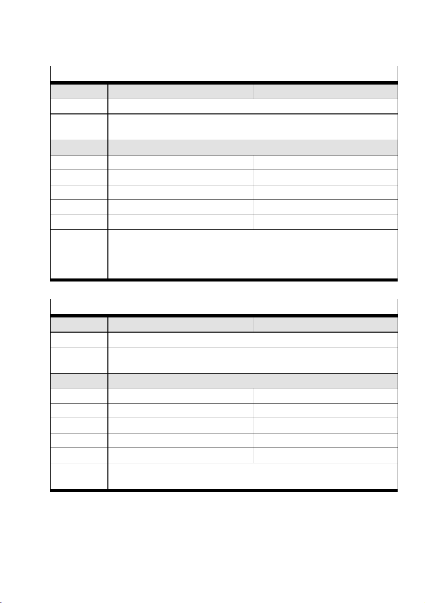
Parameter
Module parameter: Unit flow rate [Unit Flow]
Function no. 4828+m*64+8 m = module number
Description Specifies the unit for all flow-related data.
Bit Bit 2, 3: Unit flow rate
All other bits are reserved.
Values
Bit 32 Value Meaning
00 0 l/min (default)
01 1 Not permissible
10 2 scfm/10
11 3 Not permissible
Comment If parameter monitoring is active (Pm.0.7), invalid values will lead to the paramet-
erisation error FN29 è 10.1 Error numbers.
When the module parameter “Unit flow rate” is changed, the values of other flowrelated module parameters remain unchanged and are not adjusted automatically.
Tab. 36 Module parameter "Unit flow rate"
Module parameter: Unit consumption [Unit Consumption]
Function no. 4828+m*64+8 m = module number
Description Specifies the unit for all consumption-related data.
Bit Bit 4, 5: Unit consumption
All other bits are reserved.
Values
Bit 54 Value Meaning
00 0 l (default)
01 1 m³
10 2 scf
11 3 Not permissible
Comment If parameter monitoring is active (Pm.0.7), invalid values will lead to the paramet-
erisation error FN29 è 10.1 Error numbers.
Tab. 37 Module parameter "Unit consumption"
61Festo — MSE6-C2M — 2019-03
Page 62
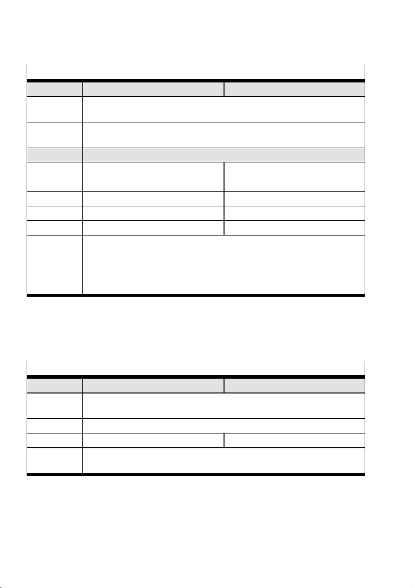
Parameter
Module parameter: Flow rate standard [Unit Flow standard]
Function no. 4828+m*64+8 m = module number
Description Specifies the flow rate standard for all data related to the flow rate and consump-
tion.
Bit Bit 6, 7: Flow rate standard
All other bits are reserved.
Values
Bit 76 Value Meaning
00 0 DIN 1343 (default)
01 1 ISO2533
10 2 ISO6358
11 3 Not permissible
Comment If parameter monitoring is active (Pm.0.7), invalid values will lead to the paramet-
erisation error FN29 è 10.1 Error numbers.
When the module parameter “Unit flow rate standard” is changed, the values of
other module parameters related to the flow rate remain unchanged and are not
adjusted automatically.
Tab. 38 Module parameter "Flow rate standard"
Module parameter “Pressure change sample time”
The parameter specifies the time of the measuring interval, during which the pressure values for the
calculation of the pressure change are determined. The set time corresponds to the parameterised
value, multiplied by 100ms. The data width is 8 bits (1 byte).
Module parameter: Pressure change sample time [Pressure change sample time]
Function no. 4828+m*64+10 m = module number
Description Specifies the time interval between two pressure measurements, from whose meas-
ured values the pressure change is calculated.
Bit Bit 0…8: Time interval between 2 measurements
Values 1…255 100 (default)…25500ms
Comment If parameter monitoring is active (Pm.0.7), invalid values will lead to the paramet-
erisation error FN29 è 10.1 Error numbers.
Tab. 39 Module parameter “Pressure change sample time”
Module parameter “Critical limits”
The module parameter “Critical limits” can be used to specify the specific critical limits “Upper critical
limit pressure”, “Upper critical limit flow rate” and “Upper critical limit pressure change”. The data
width is 16bits (2bytes).
62 Festo — MSE6-C2M — 2019-03
Page 63
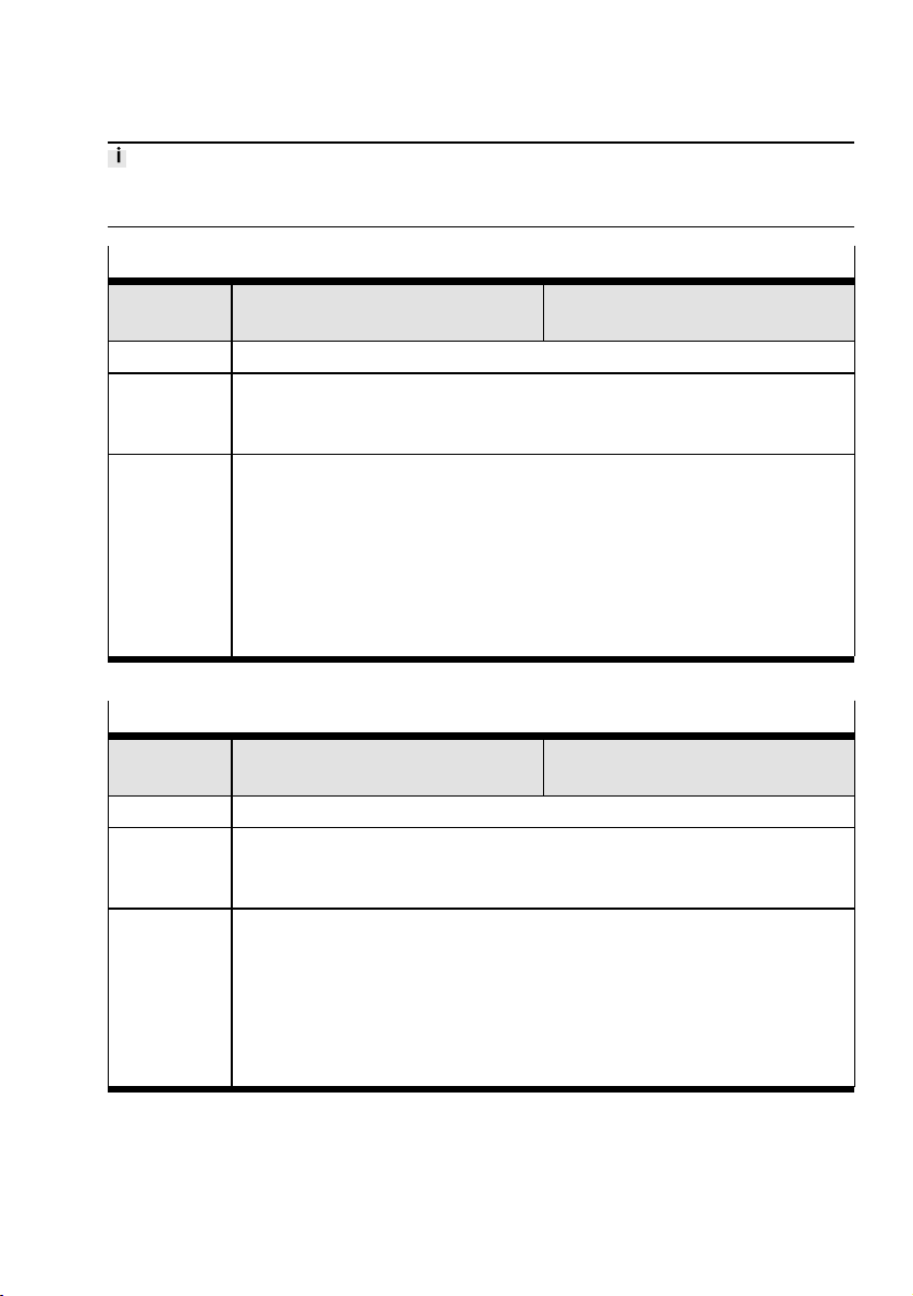
Parameter
If the unit is changed, the data for the critical limits is not changed and may need to be adjusted separately.
Module parameter: Upper critical limit flow rate [Upper limit flow]
Function no. 4828+m*64+11(low byte)
m = module number
4828+m*64+12 (high byte)
Description An upper flow limit can be set for the module.
Values 2-byte value: low byte + 256* high byte
Default: 32767 (low byte=255; high byte=127)
Permissible values: 0…32767
Comment If parameter monitoring is active (Pm.0.7), invalid values will lead to the paramet-
erisation error FN29 è 10.1 Error numbers.
If the flow rate set according to the parameterised unit exceeds the parameterised
upper critical limit, the diagnostic message FN10 is output if the parameter “Monitor critical limits” is active.
The monitoring of critical limit violation only becomes active after the expiry of the
time set in the parameter “Monitor critical limits”startup. The time is active even
after shifting to the state “Pressurise”.
Tab. 40 Module parameter "Upper critical limit flow rate"
Module parameter: Upper pressure critical limit [Upper limit pressure]
Function no. 4828+m*64+13 (low byte)
m = module number
4828+m*64+14 (high byte)
Description An upper pressure limit can be set for the module.
Values 2-byte value: low byte + 256* high byte
Default: 32767 (low byte=255; high byte=127)
Permissible values: 0…32767
Comment If parameter monitoring is active (Pm.0.7), invalid values will lead to the paramet-
erisation error FN29 è 10.1 Error numbers.
If the pressure P2 according to the parameterised unit exceeds the parameterised
upper critical limit, the diagnostic message FN10 is output if the parameter “Monitor critical limits” is active.
The monitoring of critical limit violation only becomes active after the expiry of the
time set in the parameter “Monitor critical limits”startup.
Tab. 41 Module parameter "Upper pressure critical limit"
63Festo — MSE6-C2M — 2019-03
Page 64
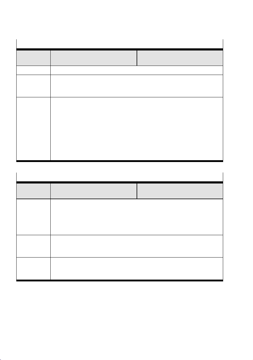
Parameter
Module parameter: Upper critical limit pressure change [Upper limit pressure change]
Function no. 4828+m*64+15 (low byte)
m = module number
4828+m*64+16 (high byte)
Description An upper pressure critical limit for pressure change can be set for the module.
Values 2-byte value: low byte + 256* high byte
Default: 32767 (low byte=160=0xA0; high byte=15=0x0F)
Permissible values: 0…32767
Comment If parameter monitoring is active (Pm.0.7), invalid values will lead to the paramet-
erisation error FN25 è 10.1 Error numbers.
If the amount of the pressure change set according to the parameterised unit
exceeds the parameterised critical limit, the diagnostic message FN10 is output if
the parameter “Monitor critical limits” is active.
The monitoring of critical limit violation only becomes active after the expiry of the
time parameterised in the parameter diagnostics “Monitor critical limits” startup.
The monitoring function is only active if the shut-off valve is in the blocking state
(Em.3.0=1).
Tab. 42 Module parameter "Upper critical limit pressure change"
Module parameter: Auto-controller delay time [Auto control delay time]
Function no. 4828+m*64+17 (low byte)
m = module number
4828+m*64+18 (high byte)
Description Time in minutes after which an uninterrupted underrun of the parameter value
“Auto-controller flow rate critical limit” switches to the expired state (UP) in the
operating mode "Automatically controlled blocking" (Am.0.1=1) of the Q_lowTimer. With the active output Auto-Enable (Am.0.5=1), the product automatically
switches to the blocking state.
Values 2-byte value: low byte + 256* high byte
Default: 10 (low byte=10; high byte=0)
Permissible values: 0…65535
Comment Changes to the parameter value are immediately effective. With an expired Q_low-
Timer, i.e. status Q_low-Timer=2 (UP), extending the delay time no longer affects
the status. In other words, there is no status change from UP to RUN.
Tab. 43 Module parameter "Auto-controller delay time"
64 Festo — MSE6-C2M — 2019-03
Page 65
Parameter
Module parameter: Auto-controller flow rate critical limit [Auto control low flow limit]
Function no. 4828+m*64+19
m = module number
4828+m*64+20
Description Flow rate critical limit that must be underrun in the "Automatically controlled block-
ing" operating mode (Am.0.1=1) on an uninterrupted basis for the parameterised
duration of the Auto-controller delay time (Pm.17-18) so that the Q_low-Timer
switches to the expired status (UP). With the active output Auto-Enable
(Am.0.5=1), the product automatically switches to the blocking state.
Values 2-byte value: low byte + 256* high byte
Default: 0 (low byte=0; high byte=0)
Permissible values: 0…32767
Comment Changes to the parameter value are immediately effective. If the shut-off valve is
already in the automatic blocking state, i.e. module status=AUTO_SHUTOFF
(Em.8-11=11), this status will not change if there is a change to the flow rate critical limit.
If parameter monitoring is active (Pm.0.7), invalid values will lead to the parameterisation error FN29 è 10.1 Error numbers.
Tab. 44 Module parameter "Auto-controller flow rate critical limit"
Module parameter: Pressure setpoint Auto Normal [Pressure setpoint auto normal]
Function no. 4828+m*64+21(low byte)
m=module number
4828+m*64+22(high byte)
Description The parameter determines the target pressure that applies when the automatic
pressure regulation and blocking function is activated in the module states
AUTO_NORMAL, AUTO_WAITand AUTO_HOLD(Em.3.8-3.11=8, 9, 10).
Values 2-byte value: low byte+256*high byte
Default: 10000 (low byte=16; high byte=39)
Permissible values: 0…32767
Parameter value Pressure setpoint Auto Normal (Pm.21-22) must be greater than
parameter value Pressure setpoint Auto Standby (Pm.23-24).
Comment If parameter monitoring is active (Pm.0.7), invalid values will lead to the paramet-
erisation error FN29 è 10.1 Error numbers.
The parameterised pressure setpoints are automatically limited within the permissible value range, depending on the parameterised pressure unit, to the end values
of the nominal pressure range within the module without an error message:
– mbar: 2500…10000
– kPa: 250…1000
– psi/10: 363…1450
Tab. 45 Module parameter "Pressure setpoint Auto Normal"
65Festo — MSE6-C2M — 2019-03
Page 66
Parameter
Module parameter: Pressure set point Auto Standby [Pressure setpoint auto standby]
Function no. 4828+m*64+23(low byte)
m=module number
4828+m*64+24(high byte)
Description The parameter determines the target pressure that applies when the automatic
pressure regulation and blocking function is activated in the module state
AUTO_STANDBY(Em.3.8-3.11=12).
Values 2-byte value: low byte+256* high byte
Default: 4000 (low byte=160; high byte=15)
Permissible values: 0…32767
Parameter value Pressure setpoint Auto Normal (Pm.21-22) must be greater than
parameter value Pressure setpoint Auto Standby (Pm.23-24).
Comment If parameter monitoring is active (Pm.0.7), invalid values will lead to the paramet-
erisation error FN29 è 10.1 Error numbers.
The parameterised pressure setpoints are automatically limited within the permissible value range, depending on the parameterised pressure unit, to the end values
of the nominal pressure range within the module without an error message:
– mbar: 2500…10000
– kPa: 250…1000
– psi/10: 363…1450
Tab. 46 Module parameter "Pressure setpoint Auto Standby"
Module parameter: Lower pressure critical limit P2 [Lower limit pressure P2]
Function no. 4828+m*64+25 (low byte)
m = module number
4828+m*64+26 (high byte)
Description For the module, a lower critical limit can be set for the output pressure P2.
Values 2-byte value: low byte + 256* high byte
Default: 4000 (low byte=160; high byte=15)
Permissible values: 0…32767
Comment If parameter monitoring is active (Pm.0.7), invalid values will lead to the paramet-
erisation error FN24 è 10.1 Error numbers.
The pressure P2 prepared according to the parameterised unit is continuously compared with the parameterised lower critical limit. The result is indicated in input
Em.3.6 and with the status LED P2.
Detailed description è 7.3 Pressure.
Tab. 47 Module parameter "Lower pressure critical limit P2"
66 Festo — MSE6-C2M — 2019-03
Page 67
Parameter
Module parameter "Signal extension channel DI0" [Signal extension channel DI0]
Function no. 4828+m*64+27 m=module number
Description The parameter determines whether the signal extension for the electrical input 0 is
active or not.
Bit Bit 0
0=not active (default) [inactive]Values
1=active [Active]
Tab. 48 Module parameter "Signal extension channel DI0"
Module parameter: Signal extension channel DI1 [Signal extension channel DI1]
Function no. 4828+m*64+27 m=module number
Description The parameter determines whether the signal extension for electrical input 1 is act-
ive or not.
Bit Bit 1
0=not active (default) [Inactive]Values
1= active [Active]
Tab. 49 Module parameter "Signal extension channel" DI1
Module parameter: Signal extension time DI [Signal extension time DI]
Function no. 4828+m*64+27 m = module number
Description The parameter defines the signal extension time for the electrical inputs 0 and 1 of
this module. Signal statuses accepted as logical input signals usually remain valid
at least until the specified signal extension time (minimum signal duration) has
expired. Signal changes within the extension time are ignored.
Bit Bit 2, 3
Values
Bit 32 Value Meaning
00 0 5ms
01 1 15ms (presetting)
10 2 50ms
11 3 100ms
Comment If a higher-order controller has long cycle times, there is the danger that short sig-
nals cannot be “detected” by this controller. So that such signals can be taken into
consideration in the control sequence, a signal extension time can be set. èCPX
system description.
67Festo — MSE6-C2M — 2019-03
Page 68
Parameter
Module parameter: Signal extension time DI [Signal extension time DI]
The signal extension time defined with this parameter applies to the electrical
inputs of this module and can be activated channel by channel with separate module parameters.
Tab. 50 Module parameter "Signal extension time" DI
Module parameter: Debounce time DI [Debounce time DI]
Function no. 4828+m*64+27 m = module number
Description The parameter determines when an edge change of the electrical inputs is to be
accepted as a logical input signal for this module.
Bit Bit 4, 5
Values
Bit 54 Value Meaning
00 0 1ms
01 1 3ms (presetting)
10 2 10ms
11 3 20ms
Comment Input debounce times are set to eliminate disturbing signal edge changes during
switching operations (bouncing of the input signal). The setting applies to the electrical inputs of this module.
Further information on this parameter èCPX system description.
Tab. 51 Module parameter "Debounce time DI"
Module parameter: Behaviour after SCS [Behavior after SCS]
Function no. 4828+m*64+27 m=module number
Description The parameter determines whether the voltage remains switched off after a short-
circuit/overload of the sensor supply 24VDCUsen or is switched on again automatically.
Bit Bit 6
0=leave deactivated [Leave switched off]Values
1=switch on again (default) [Resume]
Comment If the setting is left switched off, Power Off/On is required to restore the voltage.
– Check which setting is required for the safe operation of the system.
Tab. 52 Module parameter "Behaviour after SCS"
68 Festo — MSE6-C2M — 2019-03
Page 69
Parameter
Module parameter: Behaviour after SCO [Behavior after SCO]
Function no. 4828+m*64+27 m=module number
Description The parameter determines whether the corresponding voltage remains switched off
or is switched on again automatically after a short-circuit/overload of the electrical
outputs (Output-1) in this module.
Bit Bit 7
0=leave deactivated (default) [Leave switched off]Values
1=switch on again [Resume]
Comment If the setting is left switched off, Power Off/On or Reset/Setting of the correspond-
ing output is required for voltage recovery.
– Check which setting is required for safe operation of the system.
Tab. 53 Module parameter "Behaviour after SCO"
Module parameters: Q_low-Timer Reset selection [Q_low timer reset select]
Function no. 4828+m*64+28 m = module number
Description The parameter defines the signal source for resetting the Q_low-Timerspressure
regulation and blocking function when automatic pressure regulation and blocking
functions are activated.
Bit Bit 0, 1
Values
Bit 10 Value Meaning
00 0=Am.0.2 (default) Output Am.0.2
01 1=DI0 Electrical input 0
10 2=DI1 Electrical input 1
11 3=Am.0.2 OR DI0 Logical OR signal:
Output Am.0.2
OR
Electrical input 0
(logic 1 if Am.0.2=1 or electrical input
0=1)
Tab. 54 Module parameter Q_low-TimerReset selection
69Festo — MSE6-C2M — 2019-03
Page 70
Parameter
Module parameter: Target pressure Power-On [Pressure setpoint power on]
Function no. 4828+m*64+28 m=module number
Description The parameter is used to define the target pressure when the supply voltage is
switched on (Power-On), when the module is in user-controlled pressure regulation
and blocking function.
Bit Bit 2
0=10bar (default) [1000kPa; 1450psi/10]Values
1=6bar [600kPa; 870psi/10]
Comment The parameter value is permanently stored in the module and is the valid value for
the next power-on. A change in the parameter value is effective immediately and
can be used in user-controlled pressure regulation and blocking function to set a
target pressure fixed value.
Tab. 55 Module parameter Target Pressure Power-On
Module parameter: Output DO0 selection [Output DO0 select]
Function no. 4828+m*64+28 m=module number
Description The parameter defines the signal to be output at electrical output 0.
Bit Bit 3
Values
0: DO0=Am.0.6 (default) Signal source for the electrical output 0
is the output value Am.0.6
1: DO0=VC_PULSE Signal source for the electrical output 0
is the measuring pulse signal of the continuous consumption measurement VC
Tab. 56 Module parameter "Output DO0 selection"
70 Festo — MSE6-C2M — 2019-03
Page 71
Parameter
Module parameter: Target pressure rise limitation [Pressure setpoint rise limit]
Function no. 4828+m*64+28 m = module number
Description The parameter defines the slope as the target pressure increases. The limitation is
effective for both automatic and user-controlled operation, including Power-On. The
set rise limitation also applies when the operating mode is changed.
Bit Bit 4…6
Values
Bit 654 Value Meaning
000 0=OFF (default)
–
001 1=10bar/s [1000kPa/s; 145.04psi/s]
010 2=5bar/s [500kPa/s; 72.52psi/s]
011 3=2.5bar/s [250kPa/s; 72.52psi/s]
100 4=1bar/s [100kPa/s; 14.50psi/s]
101 5=0.5bar/s [50kPa/s; 7.25psi/s]
110 6=0.25bar/s [25kPa/s; 3.63psi/s]
111 7=0.125bar/s [12.5kPa/s; 1.81psi/s]
Comment
During the target pressure increase, the target pressure can deviate up to 15% from
the ideal value.
The parameter value is permanently stored in the module and is the valid value for
the next power-on. A change of the parameter value is effective immediately.
Tab. 57 Module parameter "Target pressure rise limitation"
71Festo — MSE6-C2M — 2019-03
Page 72
Parameter
9.3 Read-only module parameters
Module parameter: Module time of operation [Module time of operation]
Function no. 4828+m*64+29 (low byte)
4828+m*64+30 (high byte)
Description Operating time of the function module in hours.
The operating time is the duration for which the module was supplied with electrical energy.
Values Unsigned binary number with the decimal value range:
0…65535 Hours (low byte + 256* high byte)
Comment The operating time is limited to a maximum value of 65535.
The operating hours counter is increased by 1 each time the operating voltage is
switched on and then when each additional hour elapses.
If the operation takes place more often than 65535 times, the parameter remains at
this value.
This parameter can only be read.
Tab. 58 Module parameter "Module time of operation"
Module parameter: Shut-off valve switching cycles [Shut off valve cycles]
Function no. 4828+m*64+31 (low byte)
4828+m*64+32 (high byte)
Description Counts the switching cycles of the shut-off valve.
Values Unsigned binary number with the decimal value range:
0…65535 Cycles (Low Byte + 256* high byte)
Comment The switching cycles counter is limited to a maximum value of 65535.
If the operation takes place more often than 65535 times, the parameter remains at
this value.
This parameter can only be read.
Tab. 59 Module parameter "Shut-off valve cycles"
m = module number
m = module number
72 Festo — MSE6-C2M — 2019-03
Page 73

Diagnostics
10 Diagnostics
The product offers extensive possibilities of diagnosis and error handling via the fieldbus or diagnostic
interface of a CPX field bus node.
Diagnostics Description Information
Via status LEDs on
1
product
The LEDs on the module indicate the status
of the outlet pressure p2, the status of the
electrical inputs and outputs and module
errors.
Via status LEDs on CPX
field bus node
2 Locally via the bus node
diagnostic interface and
operation using the CPX
FMT (Festo Maintenance Tool)
System status scanning
3
via the network (status
The LEDs on the module indicate hardware
errors, bus errors, etc.
The CPX-FMT:
– Shows current error messages in plain
text
– Offers access to the diagnostic
memory.
The 8 status bits display common diagnostic messages (global error message).
bits scanning)
System diagnostics
with the network (via
I/O diagnostic interface)
Internal diagnostics data can be read via
the I/O diagnostics interface. In this way,
detailed diagnostic information can be
accessed, even if the network used does
not offer any extensive network-specific
diagnostic functions.
The I/O diagnostic interface offers:
– Access to the current error message
– Access to the diagnostic memory
– Read access to internal parameters and
data.
Network-specific diagnostic functions
Diagnostic functions or communication services e.g. DPV1 (PROFIBUS)
Tab. 60 Description of diagnostic options
è 5.1.2 Display
components.
CPX system description
è 3 Additional
information
è 6.3.1 Interfaces and
display components.
è 1 Applicable
documents.
CPX system description
è 3 Additional
information.
73Festo — MSE6-C2M — 2019-03
Page 74

Diagnostics
10.1 Error numbers
Error
no.
Error
chan-
1)
nel
Meaning Remedy Activation para-
No error or end of a message status [No error]0
– – –
Short circuit/overload [Short circuit]2
Em.3 Short circuit/
Overload sensor
supply
24VDC Usen
2 Am.0 Short circuit/
overload at electrical outputs on
at least one
electrical output
– Eliminate short circuit/overload and
check connected sensors if necessary.
– Depending on the set parameter value,
behaviour according to SCS (Pm.27.6):
– Setting 1= switch onagain: sensor
supply voltage is automatically
switched on again after elimination
of short-circuit/overload
– Setting 0=leave off. Switching on
the sensor supply voltage again:
Power Off/On necessary.
or
Change parameter "Behaviour after
SCS" (Pm.27.6) to 1=switch on
again
– Check the connected actuators, elimin-
ate short circuit/overload if necessary.
The number of the faulty channel is signalled in the inputs Em.3.14 (DO0) and
Em.3.15 (DO1).
meter
cannot
Can be deactivated
Pm.0.0
Monitoring
Short circuit/
Overload
Sensor supply
Pm.0.1
Monitoring
Short circuit/
Overload
Electrical outputs
74 Festo — MSE6-C2M — 2019-03
Page 75
Diagnostics
Error
no.
10
15
Error
Meaning Remedy Activation para-
chan-
1)
nel
– Depending on the set parameter "Beha-
viour according to SCO" (Pm.27.7):
– Setting 1=switch on again: output
is automatically switched on again
after elimination of short-circuit/overload
– Setting 0=leave off: output
remains reset to 0. Switch the output back on: set the output to 0 and
then set it back to 1.
or
Change parameter "Behaviour after
SCO" (Pm.27.7) to 1=switch on
again
Upper critical limit exceeded [Upper limit exceeded]
Em.0 Upper flow rate
critical limit
exceeded
– Check flow rate
– Check parameterised critical limit
– If necessary, adjust the parameter
"Monitor critical limits"startup
Em.2 Upper pressure
critical limit
exceeded
– Check pressure
– Check parameterised critical limit
– If necessary, adjust the parameter
"Monitor critical limits"startup
Em.3 Upper pressure
change critical
limit exceeded
– Check pressure change
– Check parameterised critical limit
– If necessary, adjust the parameter
"Monitor critical limits"startup
– Check system for leakage
Module/channel failure [Module/channel failure]
Em.0 Flow sensor
defective
Em.2 Pressure sensor
P2 defective
– Power off/on necessary
– If this error occurs again, replace device
– Power off/on necessary
– If this error occurs again, replace device
3)
meter
2)
Pm.0.6:
Monitoring of
critical limits
cannot
Can be deactivated
75Festo — MSE6-C2M — 2019-03
Page 76
Diagnostics
Error
no.
25
26
Error
channel
Meaning Remedy Activation para-
meter
1)
Fault in parameterisation of the lower critical limit [Fault in parametrizing lower limit]24
Em.2 An error has
occurred in the
setting of the
– Check the parameterisation undertaken
and carry out the parameterisation
again
Pm.0.7:
Monitoring of
parameters
“Lower critical
limit pressure”
P2 parameter
Fault in parameterising the upper critical limit [Fault in parametrizing upper limit]
Em.0 An error has
occurred in the
setting of the
– Check the parameterisation undertaken
and carry out the parameterisation.
Pm.0.7:
Monitoring of
parameters
“Upper critical
limit flow rate”
parameter
Em.2 An error has
occurred in the
setting of the
“Upper critical
limit pressure”
parameter
Em.3 An error has
occurred in the
setting of the
“Upper critical
limit pressure
change” parameter
Actuator supply undervoltage [Fault in actuator supply]
Am.0 Undervoltage in
load voltage
supply 24 VDC
– Load voltage supply 24 VDC and
increase if required
– Check the cabling of the load voltage
2)
Pm.0.2:
Monitoring of
Uaus/Uven
supply and repair if required.
2)
4)
76 Festo — MSE6-C2M — 2019-03
Page 77
Diagnostics
Error
no.
29
Error
Meaning Remedy Activation para-
chan-
1)
nel
Error in parameterisation [Fault in parametrizing]
Em.0 Error in setting
the parameter:
– Unit flow
– Check the parameterisation undertaken
and carry out the parameterisation
again
rate
– Flow stand-
ard
Em.1 An error has
occurred in the
setting of the
“Unit
consumption”
parameter
Em.2 An error has
occurred in the
setting of the
“Unit pressure”
parameter
Em.3 An error has
occurred in the
setting of the
“Pressure
change sample
time” parameter
Em.5 An error has
occurred in the
setting of the
“Monitor critical
limits” parameter startup
Am.0 Error in setting
the parameter
"Auto-controller
flow rate critical
limit"
meter
2)4)
Pm.0.7:
Monitoring of
parameters
77Festo — MSE6-C2M — 2019-03
Page 78
Commissioning examples of parameterisation
Error
no.
29 Am.2 Error when cre-
Error
chan-
1)
nel
Meaning Remedy Activation para-
meter
ating the parameters:
– Check the parameterisation undertaken
and carry out the parameterisation
again
Pm.0.7:
Monitoring of
parameters
– Auto
target pressure
Normal
and/or
– Auto
target pres-
sure
Standby
1) m = module number (0)
2) With active monitoring, the module displays the relevant error depending on the parameterisation. Input signals will, however, be processed further.
3) All the electrical module functions are stopped.
4) The parameter values entered will be ignored. The module operates internally with the last valid parameter values.
Tab. 61 Module-specific error numbers
11 Commissioning examples of parameterisation
11.1 Commissioning example – automatic shut-off function
Each system must be set individually. The sample values are only intended as an orientation.
78 Festo — MSE6-C2M — 2019-03
Page 79
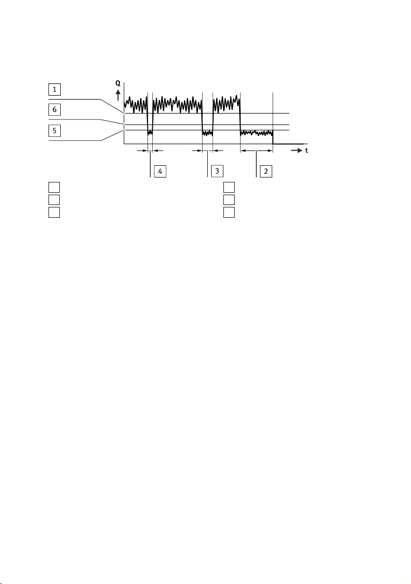
Commissioning examples of parameterisation
1
Minimum flow rate in production operation
2
Auto controller delay time
3
Short-time production downtime
4
Short-time production downtime
5
Maximum flow rate for production downtime
6
Auto controller flow rate critical limit
Fig. 20 Commissioning of the automatic pressure regulation and blocking function
Recommended procedure for determining the parameter "Auto-controller flow rate critical limits"
and "Auto-controller delay time"
1. Record the relevant function-specific production data.
To be able to set the parameters for the automatic blocking function of the product correctly, the
following data of the downstream system is required:
– Minimum flow rate in production operation
– Pneumatic and electrical system in operation
– Actuators in action
– Maximum time at continuous minimum flow rate (e.g. production downtime)
– Maximum flow rate for production downtime
– Pneumatic and electrical in operation
– Actuators not in action
Sample values in the “Pressurise” state:
– Minimum flow rate in production operation: 250l/min
– Maximum pause time in production operation: 2min
– Maximum flow rate for production downtime: 80l/min
79Festo — MSE6-C2M — 2019-03
Page 80

Commissioning examples of parameterisation
2. Set parameters for automatic pressure regulation and blocking function.
Additional tolerances and safety additions must be taken into account during parameterisation.
– The module must be in the operating mode "User-controlled blocking" (Am.0.1=0) for para-
meterisation and the automatic shut-off valve controller deactivated (Am.0.5=0).
This ensures that the Q_low-Timer is reset for activating the automatic blocking function and
the shut-off valve does not unintentionally switch to the blocking state.
– Set the parameter "Auto-controller delay time" (Pm.17-18). Here, set a greater value than the
actual production pause time to prevent unwanted blocking during production operation,
e.g. to 10min.
– Set the parameter "Auto-controller flow rate critical limit" (Pm.19-20). The parameter value
must be greater than the maximum flow rate for production downtime than the minimum flow
rate in production operation.
In the example, a parameter value can be set between 90 and 240l/min.
3. Activate automatic pressure regulation and blocking function.
– With the change to automatic pressure regulation and blocking function by setting the output
Am.0.1=1 and resetting the Q_low-Timer Reset function by Am.0.2=0, the parameterised
flow monitoring by the Q_low-Timer.
The Q_low-Timer status is indicated at input Em.3.4-3.5. When this time has elapsedQ_lowTimer, the automatic pressure regulation and blocking function is executed with supply air
shut-off and subsequent control to the target pressure Auto Standby if the output control
Auto-Enable is set (Am.0.5=1). This prevents unintentional blocking of the supply air and
reduction of the outlet pressure when the time has elapsedQ_low-Timer.
If the flow rate of the system exceeds the set Auto-controller flow rate critical limit for output
Am.0.5 that has not yet been set, the Q_low-Timer is reset. The Auto-controller delay time
starts again. It continues to control to the pressure setpoint Auto Normal, even if the output
control Auto-Enable is set (Am.0.5=1).
As soon as the module is in the state AUTO_SHUTTOFF (shut-off state) or AUTO_STANDBY
(control to pressure setpoint Auto Standby), this state can only be exited again by the user.
4. Switch the module from the blocking state (AUTO_SHUTOFF) or Auto Standby pressure regulation
state (AUTO_STANDBY) back to the Auto Normal pressure regulation state.
– The Q_low-Timer status is UP (Em.3.4-3.5=2) and the module status is AUTO_SHUTOFF
(Em.3.8-3.11=11) or AUTO_STANDBY (Em.3.8-3.11=12).
– To switch to the Auto Normal pressure regulation state AUTO_NORMAL (Em.3.8-3.11=8),
the Q_low-Timer Reset output must first be set (Am.0.2=1) and then reset (Am.0.2=0).
5. Check the set values over multiple production cycles.
Changes to system parameters can lead to a change in the determined production data.
• If necessary, check wither the set parameter values are still valid.
– The respective current module status can be tracked in input Em.3.8-3.11. The status of the
Q_low-Timers in input Em.3.4-3.5 and the switching position of the shut-off valve in input Em.3.0.
80 Festo — MSE6-C2M — 2019-03
Page 81

Commissioning examples of parameterisation
11.2 Commissioning example – monitoring of pressure drop
Each system must be set individually. The sample values are only intended as an orientation.
Recommended procedure for determining the parameters "Upper critical limit pressure change"
and "Pressure change sample time"
1. At output pressure setpoint P2 (Am.2), set the parameterised target pressure value Auto Normal
(Pm.21-22). Switch the shut-off valve at the control output to the pressurisation state
(Am.0.1=0). At the Auto-User control output, activate the user-controlled pressure regulation
and blocking function (Am.0.1=0).
2. Set the parameter "Pressure change sample time" (Pm.10).
If the system shows a high pressure drop, start with a setting of 100ms (corresponds to
Pm.10=1). If there is a lower pressure drop, increase the pressure change sample time, e.g. to
1s (Pm.10=10), the pressure change is displayed per 1s. Vary the parameter value until you
have determined a suitable value for your system.
3. Switch the shut-off valve to the shut-off state (Am.0.1=1).
4. Record pressure change values as long as the output pressure is greater than the parameterised
pressure setpoint Auto Standby (Pm.23-24). The values are available as selectable input data in
the inputs Em.5 or Em.6. The corresponding input address must first be set in Am.1. Z.B.
Am.0=0 indicates the pressure change in both Em.5 and Em.6.
The pressure change is a signed value. When the pressure falls, the values are correspondingly
negative.
5. Generate the amount of the pressure change. With positive values, adopt the input value, with
negative values, reverse the sign, e.g. –10 becomes 10.
6. Determine the amount of the largest pressure change value during the blocking state.
7. By repeatedly switching the shut-off valve from the pressurise to the shut-off state with the pressure setpoint unchanged, determine the largest pressure change value in the shut-off state in
terms of amount.
If you have obtained very low values, it may be wise to increase the value for the parameter “Pressure change sample time” (Pm.10).
81Festo — MSE6-C2M — 2019-03
Page 82

Commissioning examples of parameterisation
8. Set the specified value, with an added safety tolerance, for the parameter “Upper critical limit
pressure change” (Pm.15-16). In this way, you can avoid accidental error messages.
Sample values:
– Parameter “Pressure change sample time: 1s
– Parameter "Upper critical limit pressure change":
– Specified, amount of maximum pressure change value: 160mbar
– Set critical limit including safety tolerance: 200mbar
The monitoring of the pressure change only takes place in the blocking state and with activated
critical limit monitoring (Pm.0.6=1).
82 Festo — MSE6-C2M — 2019-03
Page 83

Page 84

Reproduction, distribution or sale of this document or communication of its contents to others without express authorization is
prohibited. Offenders will be liable for damages. All rights
reserved in the event that a patent, utility model or design patent
is registered.
Copyright:
Festo AG & Co. KG
Ruiter Straße 82
73734 Esslingen
Germany
Phone:
+49 711 347-0
Fax:
+49 711 347-2144
e-mail:
[email protected]
Internet:
www.festo.com
 Loading...