

Festo HMP-...-SL Series, HMP-25-...-SL Series, HMP-20-...-SL Series, HMP-16-...-SL Series, HMP-32-...-SL Series Operating Instructions Manual

Bedienungsanleitung
Operating instructions
Einbau und Inbetriebnahme sind nur
durchzuführen von Fachpersonal mit
entsprechender Qualifikation gemäß Bedienungsanleitung.
Fitting and commissioning must be carried out only by qualified technicians in
accord ance with these op eratin g instru ctions.
Es bedeuten:/Symbols:
Warnung
Warning, Caution
Hinweis
Note
Recycling
Recycling
Zubehör
Accessories
9912b D/GB 1
Sensorleiste für
Linearmodul HMP-...
Typ HMP-...-SL
396 406
Sensor manifold for HMP-...
linear module
type HMP-...-SL

HMP-...-SL
1
Bedienteile und Anschlüsse
Operating parts and
connections
Magnet
1
Zylinderstift zur Positionierung des
2
Magnethalters
Magnethalter
3
Nut für max. 2 Näherungsschalter
4
Enddeckel
5
Einfräsung für Kab elabgan g
6
(im En ddecke l des Line armodu ls)
Nut für max. 3 Näherungsschalter
7
Sensorleiste
8
Frontdeckel
9
Kugellaufbahn des Führungsrohrs
0
zur Winkelausrichtung des
Magnethalters
Magnet
1
Cylin der pin f or posi tionin g the
2
magnet suppor t
Magnet suppor t
3
Groove for max. 2 prox. switches
4
End cove r
5
Recess for cable exit
6
(in en d cover of lin ear modul e)
Groove for max. 3 prox. switches
7
Sensor manifold
8
Front co ver
9
Ball- bearin g trac k of the gu ide tub e
0
for se tting t he angle of the ma gnet
support
9912b D/GB 2
0
9
Fig. 1
123
54
6
7
8
2
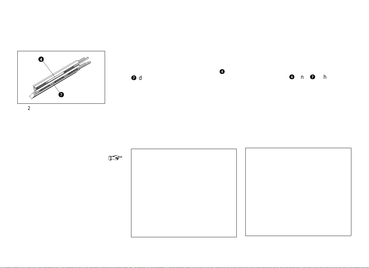
Funktion und Anwendung
Function and application
Fig. 2
4
7
Die Sensorleiste HMP-...-SL ist ein Ergänzungsmodul zum pneumatischen Li-
nearmodul HMP-... . Es können bis zu 5
Näherungsschalter in den Nuten
7
der Sensorleiste plaziert werden. Die
elektrischen Kabel werden durch eine
Profilaussparung am Enddeckel des Linearmoduls nach außen geführt. Dabei
ist die Kabelführung gemäß Fig. 2 zu
beachten.
Die Sensorleiste dient bestimmungsgemäß zur Abfrage von Endlagen- und
Zwischenpositionen mit Näherungs-
schaltern vom Typ SME-8-.../SMT-8-... .
HINWEIS:
Stark e Magn etfel der i n unm ittel bare r
Nähe des Linearmoduls (z.B. bei
Schweißanlagen) führen zu einer
Dauermagnetisierung der ferromagnetischen Teile. Die Folge ist eine
bleibe nde Ve rsc hiebu ng de r Sch altpunkte d er Nä heru ngssch alte r.
•
Stellen Sie sicher, daß starke
elekt romag neti sche Störfe lder vom
HMP-... ferngehalten werden
(z.B. mit Abschirmungen aus einem
Trafoblech).
4
und
The HMP-...-SL sensor manifold is a
supplementary module to the pneumatic
linear module type HMP-... . Up to 5
proximity switches ca n be placed in the
4
sensor grooves
cables can be pass ed out thro ugh a recess on the end cover of the linear module. Please note the cable routing as
shown in Fig. 2.
The sensor manifold is intended for
scanning both the end and intermediate
positions of the piston in the linear module. The proxim ity swi tches use d are of
type SME-8-.../SMT-8-... .
PLEASE NOTE
Strong magnetic fields in the immediate vi cinit y of th e l i ne ar m odu le ( i. e.
with welding systems) can lead to continous magnetization of the ferromagnetic parts. This results in continous
displacement of the switching points
of the proximity switches.
•
Make su re, th eref ore, t hat th ere a re
no strong fields of electromagnetic
interference in the vicinity of the
HMP-... (e.g. by screening made of
transformer magnetic steel).
and 7. The electric
9912b D/GB 3

HMP-...-SL
3
Fig. 3
Vorauss etzun gen f ür den
Condit ions of use
Produkteinsatz
HINWEIS:
Durch unsach gemäße Handha bung
entstehen Fehlfunktionen.
•
Stelle n Sie s ich er, da ß die Hinweise d ies es Kapi tel s stet s ein gehalt en wer den.
Dies m acht d as Pr oduk tverha lten
ordnungsgemäß und si cher.
•
C
%
mbar
Vergleichen Sie die Grenzwerte dieser Bed ienun gsan leitu ng mi t Ihr em
aktuel len E ins atzfal l (z .B. f ür Kräfte,
Momente, Temperaturen).
•
Berücksich tige n Sie d ie Umg ebun gsbedingungen vor Ort.
•
Verwenden Sie das Produkt im Originalzu stand ohne j egli che e igenmäch-
tige Veränderung.
PLEASE NOTE:
Incor rect h andli ng and oper atio n can
lead to malfunctioning.
•
Make sur e th at thes e inst ructi ons
are al ways ob serv ed.
The product will then operate
correct ly an d rel iabl y.
•
Compare the limit values in these
operat ing i nstru ctio ns wi th you r actual ap plic atio n (e.g . in re spec t of
forces, torques, temperatures).
•
Take th e ambi ent c ondi tions at th e
location site into consideration.
•
Use the product in its original condition w ithout und ertaki ng a ny mod ifications.
9912b D/GB 4

4
Einbau
Fitting
Einbau mechanisch
HINWEIS:
Fehlschaltungen der Näherungs-
schalt er können dur ch ein en fal sch
positi onie rten M agnet halte r oder
eine falsch positionierte Sensorleiste
entstehen.
•
Stellen Sie sicher, daß der Magnethalter und die Sensorleiste nur in
der be schri ebene n Wei se un d an
der vorgegebenen Position befestigt wird.
0 mm
Zur Vorbereitung des Magnethaltereinbaus:
•
Vollzi ehen S ie f olgen de Sc hrit te:
1. Ansch lag de s Magn ethal ters auf
Fig. 4
2
Fig. 5
9912b D/GB 5
der Enddeckelseite am Führungs-
rohr
0
plaz ieren.
3
2. Magnethalter
drehen (vom Fron tdeck el
gesehen), bis der Zylinderstift
in der ober en Kuge llau fbahn des
Führun gsro hrs an der re chten
Flanke anli egt.
3. Magnethal ter wieder herausnehm en.
4. Auflagefläche reinigen.
im Uhrzeigersinn
9
2
Mechanical fitting
PLEASE NOTE:
The prox imi ty swi tches may no t
switch co rrect ly i f the mag net su pport or the se nsor m anif old is inc orrectly positioned.
•
Make su re that the ma gnet
suppo rt and t he s ensor mani fold
are fastened only as described
and only in the position specified.
In order to prepare the magnet support
for fitting:
•
proceed as follows:
1. Place t he st op co ntour o f the
magnet suppor t on the en d cover
side of the guide tube
2. Turn the mag net supp ort
clockwise dir ection (as seen from
the front cove r
2
lies in the upper ball-bearing
pin
track of th e guid e tube on the righ t
side.
3. Remove the magnet switch again.
4. Clean the fastening surfaces.
9
0
.
3
in a
), until the cylinder

HMP-...-SL
HINWEIS:
Falsch positionierte Bauteile können
nach de m Aushärten de s Kle bers
nicht mehr korrigiert werden.
•
Berücksich tige n Sie die ve rkürz te
Aushärtezeit von ca. 10 s bei
Verw endung des Akt ivat ors gemäß
Zubehör.
Zur Befestigung des Magnethalters:
5. Anwendungshinweise von Aktivator
und Klebstoff beachten.
6. Zu r V er kür zung der Aushärtezeit
die zu verklebenden Oberflächen
mit Aktivator Loctit e 7469
gemäß Zubehör vorbehandeln.
Anschließend Klebemittel Loctite
3660 dünn auf di e Auf lage fl äche
des Magnethalters auftragen.
7. Magnethalter gem. Punkt 1 und 2
aufkleben und bis zum Aushärten
fixieren. Der Kl ebstoff härtet unter
Luftabschluß aus.
Zum Einbau der Sensorleiste:
•
Vollzi ehen S ie f olgen de Sc hrit te:
1. Führungsro hr aus fahre n.
2. Auflageflächen (A) reinigen.
PLEASE NOTE:
Incorrectly positioned components
can no lo nger b e move d when the
glue has hardened.
•
Please obse rve th e bri ef har denin g
time of appr ox. 10 s when usi ng the
activator according to Accessories.
In order to fasten the magnet support:
5. Ob se r ve the i ns tr u ct io ns f or us in g th e
acti vat or an d th e glue .
6. Apply Activator Loctite 7469 to the
surfaces to be glued as per
Accessories in order to reduce the
hardening time.
Then apply Loctite 3660 lightly to the
surface of the magnet support.
7. Glue the magnet support as per
points 1 and 2 and hold until the glue
hardens. The glue hardens under
exclusion of air.
In order to fit the sensor manifold:
•
proceed as follows:
1. Move the piston rod out.
2. Clean the fastening surfaces (A).
9912b D/GB 6

Fig. 6
Fig. 7
(A)
3. Sensorleiste in die Kontur des
HMP-Grundprofils plazieren (siehe
Fig. 6) .
4. Sensorleiste bis zum Anschlag in
Richtung Enddeckel schieben.
3. Place the sensor manifold in the
contour of the HMP base profile
(see Fig. 6).
4. Push the sensor manifold as far as
possibl e in t he di recti on of the en d
cover.
5. Klebeflächen zur Ver kürzung der
Aushärtezeit mit Aktivator Loctite
7469 vo rbeh andel n.
Sensorleiste in der beschriebenen
Posit ion m it Loct ite 3660 ei nkle ben
und bis z um Au shärte n fix ier en.
Dabei muß die gesa mte Aufl age fläche der Sensorleiste in der Kontur
aufliegen.
5. Apply Activator Loctite 7469 to the
surfaces to be glued in order to
reduce the hardening time. Glue the
sensor manifold into the position
descri bed wi th Lo ctite 3660 an d
hold until hardened. In doing this,
make sure that the complete
fastening surface of the sensor
manifold is in contact with the base
profile.
Zur Vormontage der Näherungsschalter:
•
Beac hten S ie fol gend e Punk te:
2
– der Kab elabg ang d er Näherungs-
schalter zeigt in Richtung End-
3
deckel.
– die Kabelführungsnuten sind für
folgen de Anz ahl an Näherungs-
schalt ern v orges ehen :
When pre -fit tin g the p roxim ity s witch es:
•
observe the following points:
– the cable exit for the proximity
switche s face s in t he dire ctio n
of the e nd cove r.
– the cable grooves are intended
for the following number of
proximity switches:
Vorgesehene A nzahl
an Kabeln
Fig. 9
9912b D/GB 7
Obere Nut 2
Untere Nut 3
Fig. 8
Upper sensor groove 2
Lower sensor groove 3
Fig. 8
Intended num ber
of senso r cables

HMP-...-SL
Fig. 10
Fig. 11
Fig. 12
8
(B)
•
Schieben Sie die Näherungsschalter
zur Positionsabfrage in die Sensorleiste.
Eine kurze Schaltfolge S kann durch
Näherungsschalter in getrennten Nuten realisiert werden.
•
Befestigen Sie die Näherungsschal-
ter zunächst an d er gewünschten
Stelle.
Mögliche Positionskorrekturen können im Probelauf vorgenommen werden.
•
Drücken S ie di e Kabel der Nä-
herung ssch alter in di e Kabe lfüh-
rungsn ut. Nu r dann kann die max imal vorgesehene Anzahl der Nä-
herungsschalter verwendet werden.
•
Entf ernen Sie d ie Pro fil dicht ung ( B).
Die Anschlußkabel der Näher u ngs-
schalter werden über die Einfräsung
8
im Enddeckel des Linearmoduls
nach außen gef ührt (siehe Fig. 12).
•
Push the proximity switches for scanning t he pis ton po siti on in to the s ensor manifold.
A short switching distance S can be
implemented if the proximity switches
are placed in separate sensor
grooves.
•
Fasten the proximity switches first in
the desired position.
Possible corrections to the position
can be made d uring a test run.
•
Press the cables for the proximity
switches into the cable groove.
Only in this way can the maximum
intended number of proximity
switches be used.
•
Remove the profile sealing (B).
The connecting cables for the
proximity switches are brought to the
outside through the recess
8
end cover of the linear module (see
Fig. 12).
in the
9912b D/GB 8

Einbau elektrisch
•
Verkabeln Sie die Näherungs-
schalter (z. B. mit Abschlußmodul
HMP-...-EL).
Dabei ist auf genügend Kabelreserve
für mögliche Positionskorrekturen der
Näher ungssc hal ter zu achte n.
Electrical fitting
•
Connect the cables of the proximity
switches (e.g. with terminating module type HMP-...-EL).
Make sure here that there is sufficient cable i n case th e posit ion of th e
proximity switch must later be modified.
•
Verw enden S ie st ets N äherungs-
schalter mit dem selben Schaltausgang (z.B. nur positivschaltende
Näherungsschalter - PNP).
Der Mischbetrieb von positiv- und
nullschaltenden Näh erung sschalter n
Fig. 13
5
9912b D/GB 9
ist nicht zulässig.
Inbetriebnahme
•
Starten Sie einen Probelauf des Linearmoduls.
•
Prüfen S ie im P robe lauf , ob di e gewünscht en Sc hal tpunk te der Näherungsschalter erreicht werd en.
•
Always use proximity switches with
the same switching output (e.g. only
positive-switching proximity switches
- PNP).
Mixed oper atio n with p osi tive an d
negative-switching proximity switches
is no t perm itte d.
Commissioning
•
Start a test run on the linear module.
•
During this test run check to see if
the desired switching points of the
proxi mity s wit ches ar e achi eved.

HMP-...-SL
6
Störung Möglich e Ursache Abhilfe
Näherung sschalter schaltet nicht Anschlußfehler Näherungsschalte r gemäß dessen
Mehrfachschalt ungen eines Näher ungsschalters Ungenaue Monta ge von Sensorleiste oder Magnethalter Linearmodul zu Fes to senden
LED am Näherung sschalter leuchtet nicht Mischbetrieb von positiv- und nullsch altenden Sensoren Sensoren mit de m selben
Fig. 14
Störungsbeseitigung
Bedienungsanle itung anschließen
Kabelbruch Näherungss chalter austauschen
Ungenaue Monta ge von Sensorleiste oder Magnethalter Linearmodul zu Fes to senden
Nähe rungsschalter defekt Näherungss chalter austauschen
Schaltausgang ve rwenden
Elimin a ting fa ults
Fault Possible cause Remedy
Proximity switch does not switc h Connection fault Connect proximity switch according
to relevant opera ting instructions
Cable fracture Replace proximit y switch
Fitting fault in sens or manifold or magnet supp ort Return linear module to Festo
Proximity switch def ective Replace proxim ity switch
Proximity switch switc hes several times Fitting fault in sens or manifold or magnet supp ort Return linear module to Festo.
LED on proximity switch does not light up Mixed operation w ith positive and
negative-switc hing sensors
Fig. 14
9912b D/GB 10
Always use sens ors with the same
switching outp ut

7
Typ HMP-16-...-SL HMP-20-...-SL HMP-25-...-SL HMP-32-...-SL
Bauart Sensorleiste
Einbaulage In der Kontur des HMP-G rundprofils
Zulässiger Temperaturbereich 0... max. + 60 °C
Mindest-Schaltweg: – SME-8-..
– SMT-8-...
Minimaler Abstan d der Schaltpunkte zweie r
Näherung sschalter in gleicher Nut
Werkstoffe Sensor-/Magnethalter: A l Zylinderstift: St
Fig. 15
Technische Daten
8 mm
4 mm
35 mm
Technical specifications
Type HMP-16-...-SL HMP-20-...-SL HMP-25-...-SL HMP-32-...-SL
Design Sensor manifo ld
Fitting position In the contour of the HMP base profile
Permitted temperature range 0... max. + 60 °C
Switching path: – SME-8-..
– SMT-8-...
Minimum distan ce between switching points of
two proximity sw itches in the same groove
Materials Sensor/magnet support: Al Cylinder pin: St
Fig. 15
8 mm
4 mm
35 mm
9912b D/GB 11

8
Postfach
D-73726 Esslingen
Phone +49/711/347-0
Quelltext: Deutsch
Version: 9912b
Weitergabe sowie Vervielfätigung dieses
Dokuments, Verwertung und Mitteilung
seines Inhalts verboten, soweit nicht
ausdrücklich gestattet. Zuwiderhandlun-
Zubehör
Bezeichnung Typ
Nähe rungsschalter
– elektrisch
– elektronisch
Klebemittel Loctite 3660
Aktivator Loctite 7649
Fig. 16
SME-8-...
SMT-8-...
Accessories
Designation Type
Proximity switch
– electric
– electronic
Adhesive Loctite 3660
Activator Loctite 7649
Fig. 16
SME-8-...
SMT-8-...
gen verpflic hten zu Schadenersatz. Alle
Rechte vorbehalten, insbesondere das
Recht, Patent-, Gebrauchsmuster- oder
Geschmacksmusteranmeldungen durchzuführen.
The copying, distribution and utilization
of this document as well as the communic ation of i ts cont ents to oth ers wit hout expressed authorization is prohibited. Offenders will be held liable for
the payment of damages. All rights
reserved, in particular the right to carry
out patent, utility model or ornamental
design registrations.
9912b D/GB 12
 Loading...