

Page 1
227 924
Bedienungsanleitung
Quickstepper
Typ FSS-12
Anwendung
Pneumatische Ablaufsteuerung mit bis 12 Schritten.
Schritte kurzgeschlossen.
mehr
12 Schritten werden entsprechend viele Quickstepper
hintereinander geschaltet (2 Quickstepper: bis 24 Schritte, 3: bis
36 Schritte..
Montage
Montage wahlweise auf FESTO
plattenmontage.
oder Front-
Operating instructions
Quickstepper
Type
Application
Pneumatic sequence control with up to 12 steps. If less than 12 steps
are required, the unused steps should be short-circuited. If more
than
steps are required, an appropriate number of Quicksteppers
should be connected in series (2 Quicksteppers: up to 24 steps, 3:
Fitting
A desired, either on a FESTO assembly frame
panel.
2
. ..).
or on a front
1. Frontplatte auf
2. mit beiden Handen
aufsetzen,
3. Rahmen einschnappen.
Schutzkappe,
Bestellbezeichnung 11569 FSS-K-12
Frontplatten-Bausatz
Bestellbezeichnung 11 570 FSS-F-l2
Funktion
Der Quickstepper schaltet ablaufsicher
angezeigt. Nur dieser Ausgang hat Signal,
sind
Der automatische Steuerungsablauf erfolgt in
der
Fehlt eine
Grenztaster nicht angefahren), so bleibt die Steuerung an dieser
Der Einrichtbetrieb (manuell) kann direkt am Quickstepper vorge-
nommen werden. Die Bedienelemente sind am Gerat vorhanden.
Weitere Bedienelemente sind extern
eine pneumatisch be-
wird am Schritt-
anderen
(z. B.
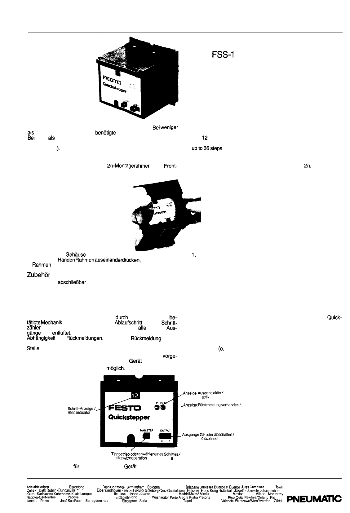
Fit front panel onto housing,
2. Press frame apart, using both hands,
3. Snap the frame in.
Accessories
Protective cap, lockable
Order code 11 569 FSS-K-l2
Front panel kit
Order code 11 570 FSS-F-l2
Function
Thanks to its pneumatically-actuated mechanical system, the
stepper provides reliable sequence switching. The sequence step
which is currently being processed is indicated on the step counter.
Only this output has a signal present, all the other outputs are exhausted. The automatic control sequence is produced as a function
of the acknowledgement signals. If an acknowledgement signal is
not present
stops at this point.
Setting operation can be carried out (manually) directly on the
Quickstepper. The control elements are fitted on the device itself.
It is possible to fit further external control elements.
Display: tis activ
Display: acknowledgement present
Connect or
oder
g. a limit switch has not been actuated), the control
outputs
Bedienungselemente
Auckland.
Oslo
San
Taste
Button for
operabon or selection of
step
Einrichtebetrieb (im Gertit enthalten). Control elements for setting operation (contained within the unit).
Bangkok
Durban
Pans Perth Port Ellabeth
Leeds
Seoul
Bordeaux.
London Lyon
Port
Stockholm Sydney
Teheran Tokyo
Melbourne
Puerto
Cute
City
Cape
FESTO
de
Page 2

(Tippbetrieb):
Output 1.
jeder
von MAN. STEP wird ein Schritt
weitergeschaltet und ausgefuhrt.
eines Schrittes:
Output
MAN. STEP betatigen bis
erscheint. Dann Output 0
auf 1 schieben: Ein Schritt
Schritt an Schritt-
wird
FSS-12
max. 6
Compressed air max. 6 bar
lnbetriebnahme
Bewegungsablauf festlegen
2. Belegung der Ein- und
Auf
A,
Ausgang 1
geben Sie immer die
Bewegung 1) zum Arbeitsventil einer Steue-
rung.
Ruckmeldung
wurde
Grenztaster ob Ausgang 1
Bewegung 1 fertig).
= Ausgang 2
=
3. Quickstepper
bis 6 bar versorgen.
Bewegung 2 fertig.
P Nennweite 4 mm mit Druckluft
Druck 3,5 bis
der nachgeschalteten Arbeitsventile beachten.)
4.
externes Richtsignal
einem Signal auf
L Nennweite 3 mm
L schaltet der
stepper auf den 12. Schritt (mu8 mindestens 200
Richten betatigen oder Schrittzahler mit Output 0 und
auf 12 stellen.
6. Einzelschritte durchtakten (zur Kontrolle) siehe
7. Signal am
Start betatigen
AUTO
AUTO Nennweite 3 mm vorsehen.
Quickstepper arbeitet, wenn Dauersignal an
des automatischen Ablaufs ansteht.
Liste..
bar, Ansteuerdruck
Signaldauer
Wartung:
Der Quickstepper arbeitet
Die Schutzkappe kann mit Seifenwasser oder Waschbenzin gereinigt
werden (kein Azeton).
Treten
(ohne
FESTO einzusenden mit Angaben tiber Druckluftversorgung,
Bedingungen und
12 gestellt und der letzte Schritt ausgefuhrt (Grun
rung).
Hinweis:
Das Arbeitsteil mu8 separat gerichtet werden.
Fehlersuche mit Hilfe der Signalanzeigen:
P zeigt an, ob Befehl am Ausgang A, bis
anzeige) vorhanden.
Input zeigt an, ob eine der
Schrittanzeige) vorhanden (Sammelanzeige).
am Quickstepper auf, so ist nur das
und eventuelle
(entsprechend Schritt-
bis
(entsprechend
an
der Steue-
Single step (inching operation):
Output 1. Each time
is actuated, the control advances
to the next step and executes this.
Preselecting a step:
Output 0. Actuate
until the desired step appears on the
step counter. Then press output 0 and shift to 1: a step is
Sub-base
I
I
Reset with manual
Commissioning
Define the motion sequence (sequence diagram, list..
2. Allocation of inputs and outputs.
Always proceed to the starting position with port
A,
Output 1
Acknowledgement, e.g. via a limit switch, to indicate whether
output 1 has been executed
Motion 1) leading to the power valve of a control.
Motion 1 complete).
= Output 2.
Acknowledgement 2, etc..
3. Supply the Quickstepper via port P, nominal size 4 mm, with
compressed air at 2.5 to 6 bar. (Ideal pressure 3.5 to 4.5 bar,
take into account the switching pressure of the downstream power
valves).
4. If appropriate, connect an external setting signal to port
nal size 3 mm. After a signal to port
to the 12th step (signal endurance at least 200 ms).
the Quickstepper switches
5. Actuate the setting control, or use output 0 and
advance the step counter to
6. Work through the individual steps (as a check); see description
of control elements.
7. Connect the start valve to the AUTO port, nominal size 3 mm.
8. Actuate START; the Quickstepper operates if a continuous signal
is present at the AUTO port during the automatic sequence.
Maintenance:
The Quickstepper is maintenance-free in operation.
The protective cap can be cleaned with soapy water or cleaning
petroleum (no acetone).
Malfunctions:
If malfunctions occur with the
send the basic unit (without sub-base, and front panel/protective
cap if fitted) to your FESTO agent with a note describing the compressed-air supply, pulse conditions and reset frequency used.
Setting
If a signal is applied to porl L (Setting), the indicator is set to 12,
and the last step is executed (return to the starting position of the
control).
Note:
The power
must be set separately.
Troubleshooting with the aid of the signal indicators:
P indicates whether an instruction is present at one of the outputs
A, to A,* (in accordance with the step indicator).
The input indicates whether one of the acknowledgements
(in accordance with the step indicator) is present (common indicator).
it is only necessary to
nomi-
to
to
Page 3

Anzeige P und
taster prufen.
Anzeige P und Schritf nicht
A-Leitung prufen.
Anzeige Input und kein Weiterschalten: Verschlauchungsfehler im
der
Schritt.
kann der
bestimmt
im angezeigten Schritt
im angezeigten Schritt
Wiih the control at a standstill, the fault can rapidly be
Indication P and step executed; check the limit switch for the
indicated step.
Indication P and step not executed; check the A-line for the in-
dicated step.
Input indication and no advance; tubing incorrect in next Step.
Technische Daten I Technical Data
I Order designation
Anzahl der Schritte I Number of steps
Anzahl der
Anzahl der
Druckbereich I Pressure range
Schutzart (mit Schutzkappe) I Degree of protection (with protective cap)
Medium
Temperaturbereich /Temperature range
Werkstoff I Materials I
Min.
Number of outputs
I Number of inputs
P I Connections Compressed-air supply P
I Outputs/inputs
L I START/Set L
P
A I Standard nominal flow rate P
A
L) I Min. reset pulse (port L)
11568 FFS-12
max.
12
bis
to 6 bar
JP 54
5
5
filtered, non-lubricated compressed air
-1.5 bis /to
Stecknippel NW 4 /barbed fitting 4 mm
Stecknippel NW 3 I barbed fitting 3 mm
Stecknippel NW 3 I barbed fitting 3 mm
70
Housing:
nicht
(-15
Sub-base:
trockener
I
I-15°C with dry air)
iinderungen vorbehalten
The right to modification is reserved
Page 4
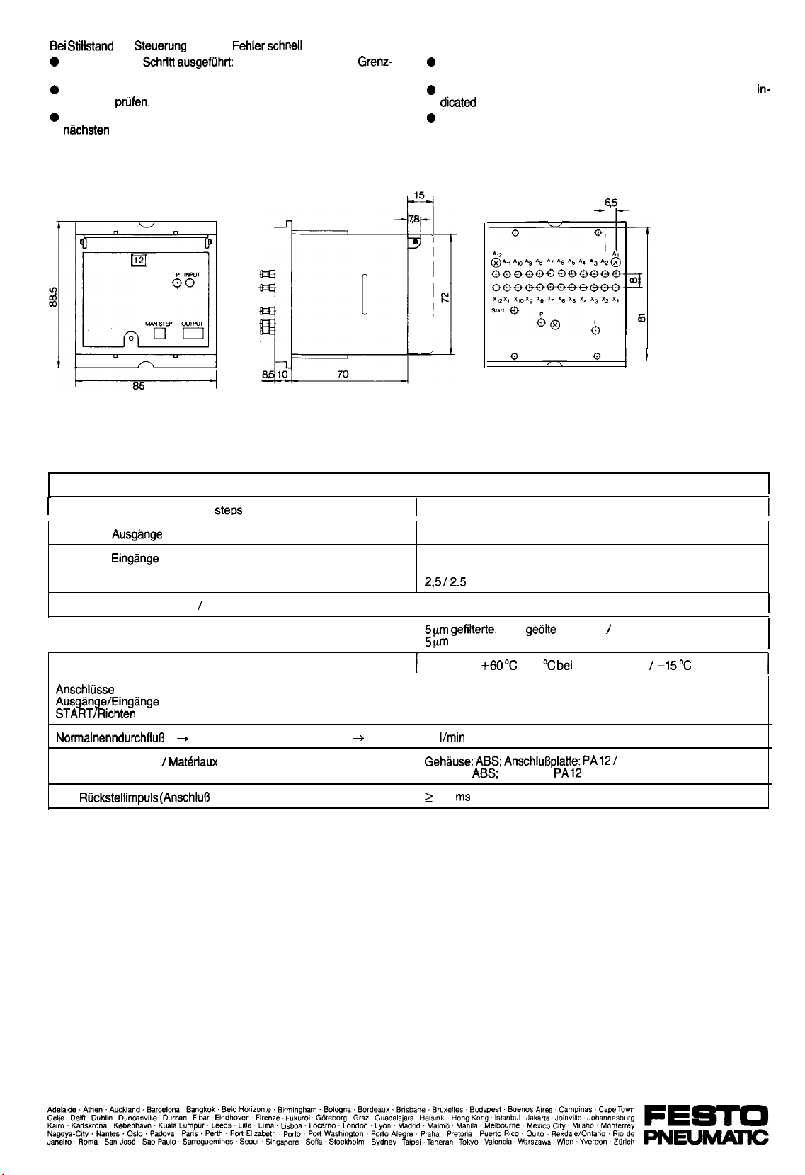
Anzeige P und
taster prufen.
Anzeige P und Schritt nicht ausgefuhrt: im angezeigten Schritt
A-Leitung prufen.
Anzeige Input und kein Weiterschalten: Verschlauchungsfehler im
der
Schritt.
kann der
bestimmt werden:
im angezeigten Schritt
With the control at a standstill, the fault can rapidly be located:
Indication P and step executed; check the limit switch for the
indicated step.
Indication P and step not executed; check the A-line for the in-
step.
Input indication and no advance; tubing incorrect in next step.
Technische Daten /Technical Data
Bestellbezeichnung I Order designation
Anzahl der Schritte I Number of
Anzahl der
Anzahl der
Druckbereich I Pressure range
Schutzart (mit Schutzkappe)
Medium
Temperaturbereich I Temperature range
Luftversorgung P I Connections Compressed-air supply P
Werkstoff I Materials
Min.
I Number of outputs
I Number of inputs
Degree of protection (with protective cap)
I Outputs/inputs
L /START/Set L
P
A I Standard nominal flow rate P
Materiaux
L) I Min. reset pulse (port L)
11568 FFS-12
max.12
12
12
bis I to 6 bar
JP 54
filtered, non-lubricated compressed air
-15 bis /to
Stecknippel NW 4 I barbed fitting 4 mm
Stecknippel NW 3 I barbed fitting 3 mm
Stecknippel NW 3 I barbed fitting 3 mm
A
70
Housing:
180
nicht
(-15
Sub-base:
Druckluft
trockener Luft
with dry air)
Anderungen vorbehalten
The right to modification is reserved
Page 5
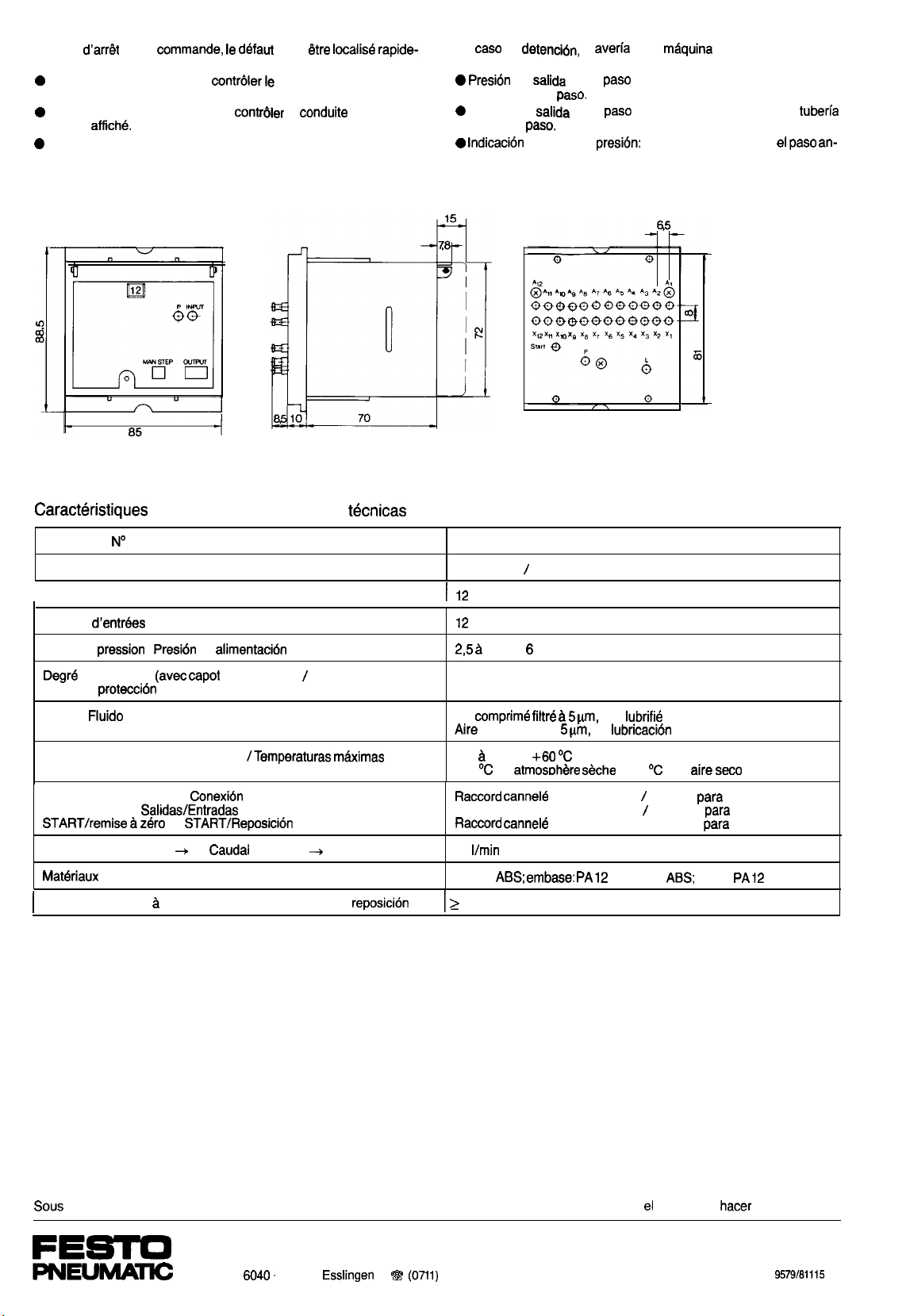
En cas
de la
defaut peut
localise
ment:
Indication P et pas execute:
le capteur de fin de course
du pas execute.
Indication P et pas non execute: contrbier la
A au niveau
du pas
Indication input sans commutation au pas suivant: erreur de
raccordement au niveau du pas suivant.
En
de
muy rapidamente:
en salida (P) y
carrera en este
Presion en salida (P) y
A de este
INPUT sin
terior.
la
en la
puede ser localizada
realizado: comprobar el final de
no realizado: comprobar la
error de conexion en
techniques I Caracteristicas
Reference I
Nombre de pas I Numero de pasos
Nombre de sorties I Numero de Salidas
Nombre
Plage de
de protection
Grado de protecci6n (con caperuza)
Fluide I
Plage des temperatures admissibles
Ftaccords Alimentation P I
Sorties/Entrees I
Debit nominal normal P
lmpulsion de remise
Articulo
I Numero de Entradas
I
a
I Materiales
zero min. (Orifice L) I lmpulsio de
L I
de
de protection)
A I
P
nominal P
maximas
A
11568 FSS-12
12 pas max.
12 maxim0
I hasta
bars I bar
JP54
Air
non lubrifie I
comprimido a sin
-15
I hasta
-15
en
Flaccord cannel6 0 de passage 3
70
(L)
Corps:
2 180 ms
I -15
con aire
0 de passage 4
Boquilla para tubo 0 int. 4 mm
Boquillas
tubos 0 int. 3 mm
0 de passage 3 I Boquillas para tubos 0 int. 3 mm
I Cuerpo:
Base:
reserve de toutes modifications Reservado
Postfach 6040. D-7300
1
l 347-0. l l 722727-0
derecho de
modificaciones
Gg
Page 6
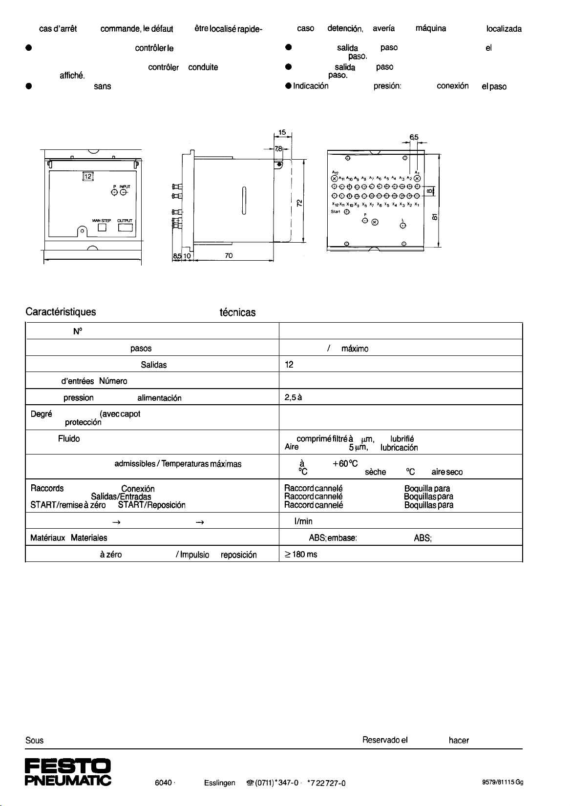
En cas
ment:
Indication P et pas execute:
du pas execute.
de la
le defaut peut
capteur de fin de course
l Indication P et pas non execute: contr~ler la
du pas
Indication input
raccordement au niveau du pas suivant.
commutation au pas suivant: erreur de
85
A au niveau
En case de
muy rapidamente:
Presion en salida (P) y
carrera en este
Presion en salida (P) y
A de este
terior.
INPUT sin
la
en la
realizado: comprobar
no realizado: comprobar la tuberfa
error de
puede ser localizada
final de
en
an-
techniques I Caracterkticas
Reference I
Nombre de pas I Numero de
Nombre de sorties I Numero de
Nombre
Plage de pression I Presion de
de protection
Grado de protecci6n (con caperuza)
Fluide I
Plage des temperatures
Sorties/Entrees I
Debit nominal normal P
lmpulsion de remise
Articulo
I
Alimentation P I
L I
I Materiales
de Entradas
capot de protection) I
A I Caudal nominal P
min. (Orifice L)
11568 FSS-12
12 pas max.
12
JP54
Air cornprime
comprimido a sin
P
maximas -15 h I hasta
A
de
(L)
-15
70
Corps:
12 maxim0
I hasta 6 bars I bar
h 5
en atmosphere
0 de passage 4 I
0 de passage 3 I
0 de passage 3 I
PA 12 I Cuerpo:
non lubrifie I
I -15
con
para tubo 0 int. 4 mm
para tubos 0 int. 3 mm
tubos 0 int. 3 mm
Base: PA 12
reserve de toutes modifications
Postfach 8040. D-7300
1
derecho de
l
modificaciones
 Loading...