

Page 1
Bedienungsanleitung
Operating instructions
Pneumatisch-elektrisches
Abschlußmodul
Typ HMP-...-AD/-EL
Einbau und In betr iebna hme
nur von qual ifiz ierte m Fach per sonal ,
gemäß B edien ungs anlei tung .
Fitting and commissioning to be
carried out by qualified personnel
only in acco rdan ce with the op erat ing
instructions.
Es bedeuten/Symbols:
Warnung
Warning, Caution
Hinweis
Note
Recycling
Recycling
Zubehö r
Accessories
0001a D/GB 1
397 780
Pneumatic-electric
end module
type HMP-...-AD/-EL
Page 2
HMP-...-AD/- EL
1
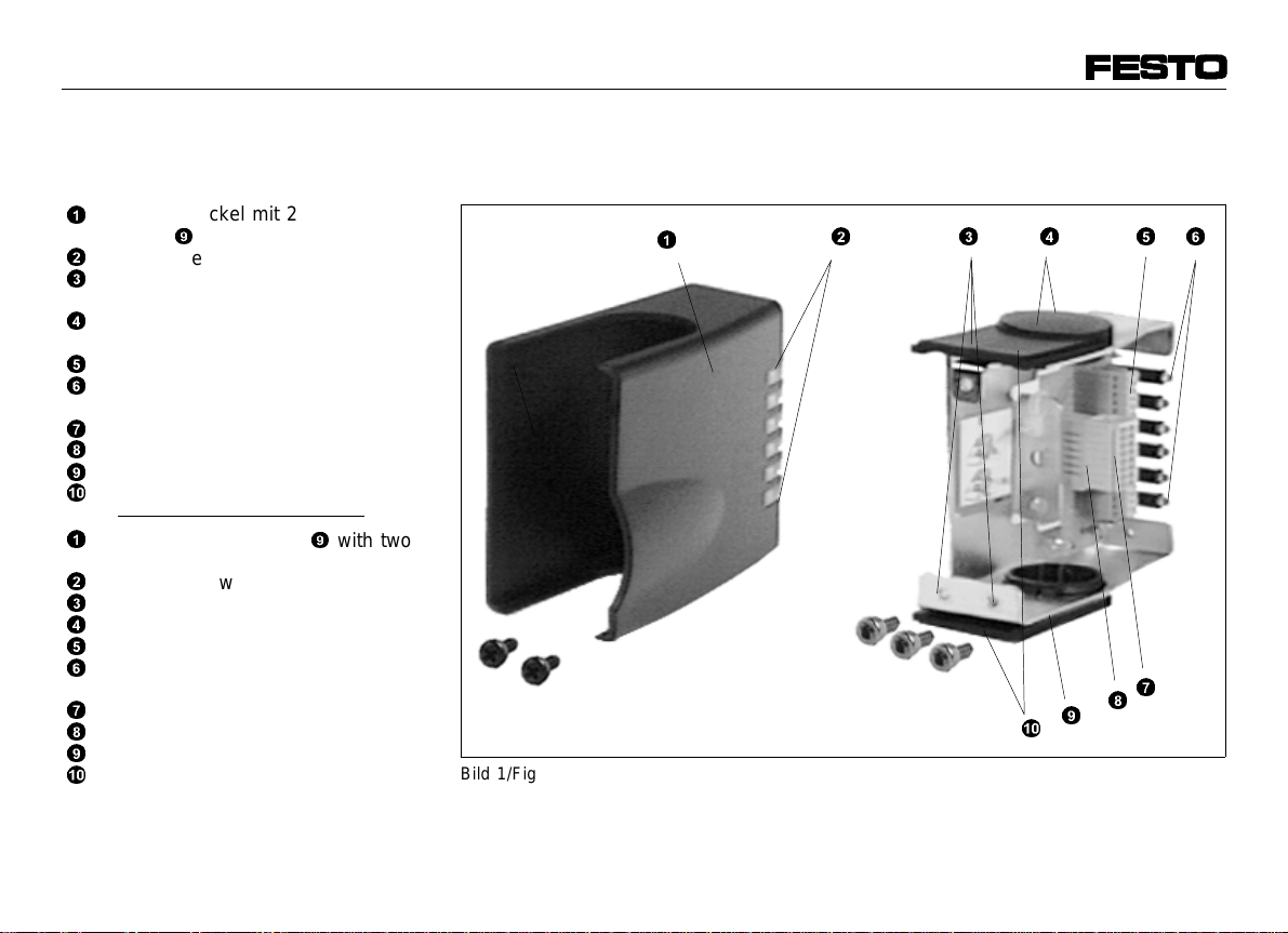
Bedienteile und Anschlüsse Operating parts and
connections
Abschlußdeckel mi t 2 Schr auben
1
M 3 an
Sichtfenster für LED’s
2
Bohrun gen zur Befest igung de s
3
Abschlußmoduls
4
Verschlußkappe für Kab elaustrittsöffnung
Klemmleiste für Sensorenk abel
5
6
Gelbe LED’s für Schaltzustandsanzeige für sechs mögliche Sensor en
Stecke r für Sa mmelkab el
7
Steckersockel
8
Metallträger
9
Einschubblende
0
1
End cove r fasten ed at 9 with two
M 3 screws
LED display window
2
3
Holes f or fast ening the end modu le
End cap f or cable exit
4
Terminal strip for sensor cables
5
6
Yellow LEDs for switching status
displa y of six possible sensor s
Plug for common cable
7
8
Plug ba se
Metal su pport
9
Slide-in screen
0
0001a D/GB 2
9
befest igt
Bild 1/Fig. 1
1
0
43
7
8
9
256
Page 3
2
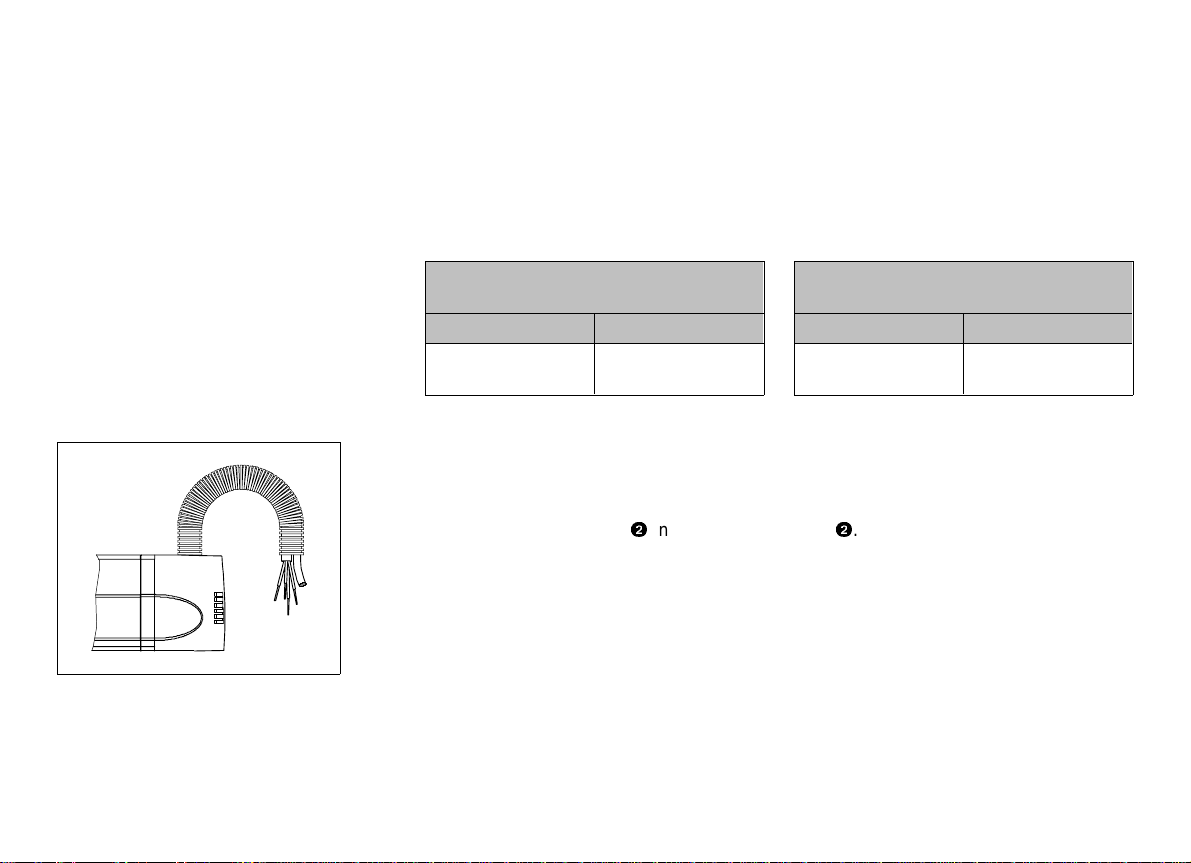
Funktion und Anwendung
Function and application
Bild 3/Fig. 3
Das pneumatisch-elektrische Abschlußmodul HMP-...-AD/-EL dient be-
stimmungsgemäß zur zentralen Zufüh-
rung folgender Versorgungsleitungen:
Mögliche ze ntrale Zuführung von
Versorgungsleitun gen
HMP-...-AD HMP-...-EL
– pneumatis ch – pneum atisch
– elektrisch
Bild 2
Die elektrischen Kabel können an einem
Sammelanschluß verkabelt werden. Der
Schaltzustand von bis zu sechs Sensoren wird durch LED’s angezeigt, die
durch die Sichtfenster
2
nach außen
durchscheinen. Sämtliche Versorgungsleitungen werden mit Hilfe eines Kabelschutzschlauchs abgeführt.
The pneumatic-electric end module
HMP-...-AD/-EL is used for grouping together the following supply lines:
Possible central gr ouping of
supply lines
HMP-...-AD HMP-...-EL
– pneum atic – pneumatic
– electric
Fig. 2
The electrical connections can be made
with a common cable. The switching
status is indicated by LEDs which are
visible from the outside through a window
2
. All supply cables have protecti-
ve tubing.
0001a D/GB 3
Page 4

HMP-...-AD/- EL
4
C
Bild 4/Fig. 4
3
Voraussetzungen für den
Condit ions of us e
Produkteinsatz
Allgemeine, stets zu beachtende Hinweise für den o rdnungs gemäßen und sicheren Einsatz des Produkts:
•
Vergleichen Sie die angegebenen
Grenzwerte mit Ihrem Einsatzfall.
%
mbar
Die zulässigen Grenzwerte, z.B. für
Momente und Temperaturen dürfen
nicht überschr itten werden.
•
Verwen den Sie das P rodu kt im O rigi nalzustand ohne jegliche eigenmäch-
tige Veränderung.
Einbau
mechanisch
•
Befestigen Sie das Abschlußmodul
wie folgt:
These general conditions for the correct
and safe use of the product must be observed at a ll ti mes.
•
Compare the specified values with
your ap plic atio n.
Please observe the specified limits
(e.g. for moments and temperatures).
•
The pr oduc t mus t be us ed in i ts ori ginal s tate . Unau thori zed m odif icati on
is not permitted.
Fitting
Mechanical
•
Fasten the en d modu le a s fol lows :
0001a D/GB 4
Page 5

1. Die zwei Schrauben aus dem Ab-
schlußdeckel drehen (gut verwahren).
1. Unscrew the two screws from the end
cover (keep in a safe place).
Bild 5/Fig. 5
Bild 6/Fig. 6
2. Abschlußdeckel vom Metallträger
9
herunterziehen .
3. Metallträger mit drei beiliegenden
Schrauben M5 am hinteren Enddeckel
des Linearmoduls HMP-... befestigen.
•
Montie ren S ie den Kabel sch utzschlauch wie folgt:
1. Kabelaustrittsöffnung wählen.
2. Verschlußkappe
0
blende
4
entfernen. Einschub-
dabei nicht demontieren.
3. Verschraubung mit Gegenmutter befestigen (siehe Zubehör).
4. Pneumatikschläuche und elektrisches
Sammelkabel (nur bei HMP-...-EL)
durch Verschraubung und Kabelschutzschlauch (siehe Zubehör) füh-
ren.
5. Kabelschutzschlauch in Verschraubung
einstecken.
2. Pull the end cover down from the Metallträger
9
end module.
3. Fasten the metal support to the rear
end cover of linear module HMP-...
with the three M5 screws supplied.
•
Fit the protective cable as follows:
1. Select cable exit.
2. Remove the end cap
remove the slide-in screen
4
. Do not
0
.
3. Fasten the screw connector with the
lock nut (see "Accessories").
4. Pass the pneumatic tubing and the
common electric cable (only on HMP...-EL) through the screw connector
and the protective tubing (see "Accessories").
5. Plug in the protective tubing.
0001a D/GB 5
Page 6

HMP-...-AD/- EL
Y
/
1
Y
/
1
Bild 7/Fig. 7
elektrisch
•
Verw enden S ie nur Net ztei le, di e
eine si che re elek tri sche T rennu ng
der Betriebsspannung nach IEC 742/
EN 6074 2/VD E 0551 m it mi ndest ens
4 kV Isolationsfestigkeit gewähr-
Electrical
•
Use only power units which ensure
reli able e lect ric al is olat ion of t he
operat ing v olta ges wi th at leas t 4 kV
isolation resistance as per
IEC 74 2/ EN 60 742/V DE 055 1.
leisten.
Schaltnetzteile sind zulässig, wenn
sie d ie si chere Tren nung i m Sinne
der EN 60950/ VDE 0805
Switch power pac ks are permi tted
provi ding t hey en sure reli able
isolation as per EN 60950/VDE 0805.
gewährleisten.
•
Verw enden S ie st ets S enso ren mi t
dem sel ben Sc hal tausg ang ( z.B. nu r
positivschaltende Sensoren - PNP).
Der Mischbetrieb von positiv- und
nullschaltenden Sensoren ist nicht
zulässig.
Y
1/1
Zur Einstellung des zulässigen Scha ltausgangs:
•
Positionieren Sie den Jumper
!
ge-
mäß Bild 7 für positivschaltende Sen-
!
Y
/1/
soren (PNP; Werkseinstellung) oder
nullschaltende Sensoren (NPN).
•
Alway s use se nsor s wit h the s ame
switching output (e.g. only positiveswitching sensors - PNP).
Mixed operation with posit ive and negative-switching sensors is not permitted.
Setting the permitted switching output
•
Position the jumper
!
as shown in
Fig. 7 for positive-switching sensors
(PNP; factory setting) or negativeswitching sensors (NPN).
0001a D/GB 6
Page 7

•
Verkabeln Sie die elektrischen Anschlüsse wie folgt (siehe Bild 8 u. 9):
•
Wire t he el ectri cal co nnec tions a s fo llows ( see Fig. 8 a nd 9) :
Bild 8/Fig. 8
Bild 9/Fig. 9
Bild 10/Fig. 10
1. Sensoren an der Klemmleiste
5
beln (auf Polung der Sensoren achten)
7
2. Stecker für Sammelkabel
8
Steckersockel
abziehen.
vom
3. Adern abisolieren (Abisolierlänge:
ca. 6 mm).
4. Stecker verkabeln und wieder aufstecken. Sensoradern dabei nicht quetschen.
5. Sammelkabel mit Kabelbinder am
Metallträger fixieren (Zugentlastung).
•
Befestigen Sie den Abschlußdeckel
mit den beiliegenden Schrauben.
verka -
1. Connect the terminal strip
5
for the
sensors (check polarity of the sensors).
2. Disconnect the plug for the common
7
cable
from the plug base 8.
3. Remove approx. 6 mm of insulation
from the cable core.
4. Connect the plug and insert it again.
Do not squeeze the sensor cables.
5. Fix the common cable at the metal support with a cable binder (strain relief).
•
Fasten the en d cov er wi th the
screws supplied.
0001a D/GB 7
Page 8

HMP-...-AD/- EL
5
6
Inbetriebnahme
•
Star ten Si e eine n Pro belau f an hand
der Bedienungsanleitung des Linearmodul.
•
Prüfen S ie im P robe lauf , ob fol gen de
Punkte erfüllt sind:
– LEDs zei gen den gef ord erten
Schaltzustand an
– Kabels chutz schl auch w ird nicht
unzuläs sig geboge n ode r ged ehnt
(siehe Technische Daten).
Wartun g und Pflege
•
Reinigen Sie im Falle von Verschmutzungen das HMP-... mit einem weichen Lappen.
Zulässige Reinigungsmedien sind:
– Seifenlauge (max. +60
– alle werkstoffschonenden Medien.
o
C) und
Commissioning
•
Start a test run with t he oper atin g instructions with the linear module.
•
During the test run, check whether
the following conditions are fulfilled:
– the LEDs show the required
operat ing s tatu s
– the protective tubing must not be
bent or stret che d (se e "Tec hnic al
Specifications").
Care an d ma inten ance
•
If the HMP-... is dirty, clean it with a
soft cloth.
Permitted cleaning agents are:
– soap suds (ma x. +60
– non-ab rasi ve agen ts.
o
C) and all
0001a D/GB 8
Page 9

7
Störungsbeseitigung
Störung mögliche U rsache Abhilfe
LED leuchte t nicht – Anschlußfehler
– unzuläss ige Kabelbiegung
Jumpereinstellun g an der HMP-
...-EL entspricht nicht dem
Schalterausga ng der Sensoren
Druckluftversor gun g
unterbrochen
Bild 11
Kabelschutzschla uch zu stark
gebogen
beheben
Jumper an der HMP-...-EL
gemäß Kapitel ’Einba u
elektrisch’ plazieren
Zul. Mindest-Biege radius
einhalten (siehe Techn ische
Daten)
Eliminating faults
Fault Possible causes Remedy
LED does not light up – Connection fau lt or
– cable is bent
Jumper setting on HMP-...-EL
does not corresp ond to switching
output on sensor s.
Compressed air
supply interrupted
Fig. 11
Cable protection tub ing bent too
much
Rectify
Position jumper on HMP-EL
as per chapter "Elec trical
fitting"
Observe max. perm itted
bending radius for cable
protection tubing (s ee
”Technical specifications”)
0001a D/GB 9
Page 10

HMP-...-AD/- EL
8
Typ HMP-...-AD HMP-...-EL
Bauart Pneumatisches A bschlußmodul Pneuma tisch-elektrische s Abschlußmod ul
Einbaulage am hinteren Enddeckel de s Linearmodul HMP-... gemäß Bohr bildcodierung
Zulässiger Temperat urbereich 0 ... max. +60
Schutzart nach EN 605 29 IP 40 IP 40
Zul. Leitung squerschnitt – 0,08 ... max. 0,5 mm
Abisolierläng e – 5 - 6 mm
Zul. Minde st-Biegeradiu s für
Kabelschut zschlauch (statisch )
Werkstoffe Abschlußdeck el: PA
Bild 12
Technische Daten
o
C
MKR-...-PG-21 > 45 mm
MKR-...-PG-29 > 50 mm
MKG-20-PG-21 > 130 mm
MKG-23-PG-29 > 155 mm
MKG-37-PG-29 > 205 mm
Sichtfenster: PC
Blechwinkel: St, verzinkt
Klebemittel: Adhäsionskleber
2
/AWG 28-20
0001a D/GB 10
Page 11

Technical specifications
Type HMP-...-AD HMP-...-EL
Design Pneuma tic end module Pneumatic-e lectric end module
Fitting position On rear end cover of linear module HMP-...
o
Permitted temperature r ange 0 ... max. +60
Protection class as per EN 60529 IP 40 IP 40
Permitted cable cross section – 0.08 ... max. 0.5 mm
Insulation removed – 5 - 6 mm
Max. permitted ben ding radius for cable pro-
tection tubing
MKR-...-PG-21 > 45 mm
MKR-...-PG-29 > 50 mm
MKG-20-PG-21 > 130 mm
MKG-23-PG-29 > 155 mm
MKG-37-PG-29 > 205 mm
Materials End cover: PA
Window: PC
Sheet met al angle: St, galvan ized
Adhesive
Fig. 12
C
2
/AWG 28-20
0001a D/GB 11
Page 12

Postfach 6040
9
D-73726 Esslingen
Phone +49
/ 711 / 347-0
Zubehör
Accessories
Quelltext: deutsch
Version: 0001a
Weitergabe sowie Vervielfätigung dieses
Dokuments, Verwertung und Mitteilung
seines Inhalts verboten, soweit nicht
ausdrücklich gestattet. Zuwiderhandlungen verpflic hten zu Schadenersatz. Alle
Rechte vorbehalten, insbesondere das
Recht, Patent-, Gebrauchsmuster- oder
Geschmacksmusteranmeldungen durchzuführen.
Bezeichnung Typ
Kabelsch utz-
schlauch
Verschraubung MK..V-...
Gegenmutter MKM-...
Sammelkabe l KH MP -1- 8x0,25-X
Bild 13
MKR-... / MKG-...
Designation Type
Protective
tubing
Screw connector MK..V-...
Lock nut MKM-...
Common cable KHMP-1-8x0,25-X
Fig. 13
MKR-... / MKG-...
The copying, distribution and utilization
of this document as well as the communic ation of i ts cont ents to oth ers wit hout expressed authorization is prohibited. Offenders will be held liable for
the payment of damages. All rights
reserved, in particular the right to carry
out patent, utility model or ornamental
design registrations.
0001a D/GB 12
 Loading...