

Page 1
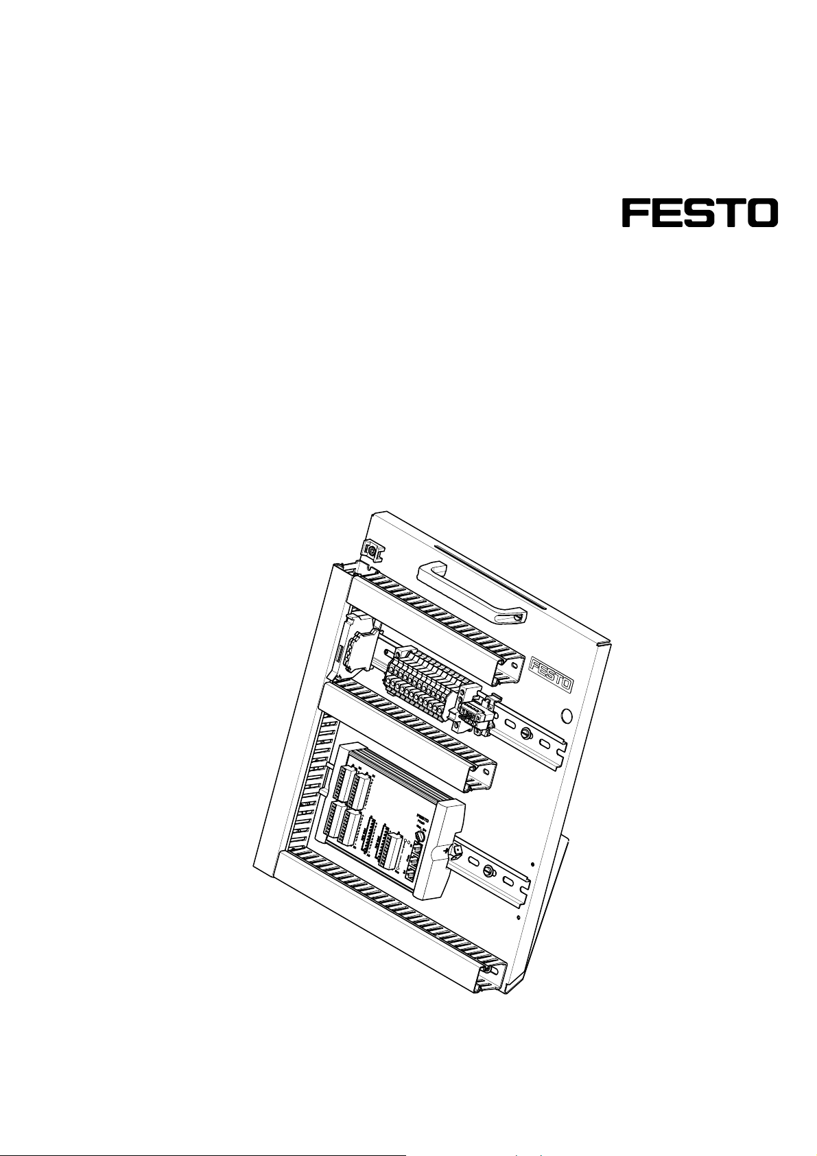
SPS-Board
FESTO
®
FEC
Standard
Handbuch
PLC board
FESTO
®
FEC
standard
Manual
668858 DE/EN
07/05
Page 2

Bestimmungsgemäße Verwendung/Intended use
Dieses SPS-Board ist ausschließlich für die Aus- und Weiterbildung im Bereich
Automatisierung und Technik entwickelt und hergestellt. Das
Ausbildungsunternehmen und/oder die Ausbildenden hat/haben dafür Sorge zu
tragen, dass die Auszubildenden die Sicherheitsvorkehrungen, die in den
begleitenden Handbüchern beschrieben sind, beachten.
Festo Didactic schließt hiermit jegliche Haftung für Schäden des Auszubildenden,
des Ausbildungsunternehmens und/oder sonstiger Dritter aus, die bei
Gebrauch/Einsatz des SPS-Boards außerhalb einer reinen Ausbildungssituation
auftreten; es sei denn Festo Didactic hat solche Schäden vorsätzlich oder grob
fahrlässig verursacht.
This PLC board has been developed and produced solely for vocational and further
training purposes in the field of automation and technology. The company
undertaking the training and/or the instructors is/are to ensure that trainees
observe the safety precautions described in the manuals provided.
Festo Didactic herewith excludes any liability for damage or injury caused to
trainees, the training company and/or any third party, which may occur if the system
is in use for purposes other than purely for training, unless the said damage/injury
has been caused by Festo Didactic deliberately or through gross negligence.
Bestell-Nr./Order No.:
Stand/Status:
Autoren/Authors:
Grafik/Graphics:
Layout/Layout:
668858
07/2005
Frank Ebel, Remo Jedelhauser, Markus Pany
Doris Schwarzenberger
07/2005
© Festo Didactic GmbH & Co. KG, D-73770 Denkendorf, 2005
Internet:
e-mail:
www.festo-didactic.com
Weitergabe sowie Vervielfältigung dieses Dokuments, Verwertung und Mitteilung
seines Inhalts verboten, soweit nicht ausdrücklich gestattet. Zuwiderhandlungen
verpflichten zu Schadenersatz. Alle Rechte vorbehalten, insbesondere das Recht,
Patent-, Gebrauchsmuster- oder Geschmacksmusteranmeldungen durchzuführen.
The copying, distribution and utilisation of this document as well as the
communication of its contents to others without express authorisation is prohibited.
Offenders will be held liable for the payment of damages. All rights reserved, in
particular the right to carry out patent, utility model or ornamental design
registration.
2
© Festo Didactic GmbH & Co. • 668858
Page 3

Inhalt/Contents
1. Einleitung ____________________________________________________ 5
2. Sicherheitshinweise ____________________________________________ 6
3. Aufbau und Funktion____________________________________________ 7
3.1 Lieferumfang __________________________________________________ 8
3.2 Zubehör ______________________________________________________ 8
3.3 Anschluss externer Geräte _______________________________________ 9
3.4 Einbauweise__________________________________________________ 10
3.5 Ein-/Ausgänge ________________________________________________ 10
3.6 NOT-AUS Funktion_____________________________________________ 10
4. Inbetriebnahme mit MPS
®
______________________________________ 11
4.1 Kabelverbindungen ____________________________________________ 11
5. Kontaktbelegungstabelle_______________________________________ 13
5.1 Ein-/Ausgänge (digital) _________________________________________ 13
5.2 NOT-AUS Stecker/Klemme ______________________________________ 14
6. Technische Daten _____________________________________________ 15
Anhang __________________________________________________________ 17
Elektrische Schaltpläne_________________________________________ 17
© Festo Didactic GmbH & Co. • 668858 3
Page 4

Inhalt/Contents
1. Introduction__________________________________________________ 21
2. Notes on safety _______________________________________________ 22
3. Design and function ___________________________________________ 23
3.1 Scope of delivery ______________________________________________ 24
3.2 Accessories __________________________________________________ 24
3.3 Connection of external equipment ________________________________ 25
3.4 Installation options ____________________________________________ 26
3.5 Inputs/outputs________________________________________________ 26
3.6 EMERGENCY STOP function______________________________________ 26
4. Commissioning with MPS
®
______________________________________ 27
4.1 Cable connections _____________________________________________ 27
5. Contact allocation table ________________________________________ 29
5.1 Inputs/outputs (digital)_________________________________________ 29
5.2 EMERGENCY STOP plug/terminal _________________________________ 30
6. Technical data ________________________________________________ 31
Appendix __________________________________________________________ 33
Electrical circuit diagrams _______________________________________ 33
4
© Festo Didactic GmbH & Co. • 668858
Page 5

1. Einleitung
Die IPC FEC® Standard ist ein modulares SPS-System der Firma Festo für den
Industrieeinsatz. Für die Verwendung in der Aus- und Weiterbildung wurde die SPS
in eine didaktische Umgebung im Festo Didactic MPS
®
-System integriert.
Die digitalen Ein- und Ausgänge sind auf zwei SysLink-Kabel (IEEE 488) verdrahtet.
Die Pin-Belegung entspricht der SysLink-Schnittstelle des Modularen ProduktionsSystems (MPS
®
) von Festo Didactic.
© Festo Didactic GmbH & Co. • 668858 5
Page 6

2. Sicherheitshinweise
Die SPS-Boards sind nach dem heutigen Stand der Technik und den anerkannten
sicherheitstechnischen Regeln gebaut. Dennoch können bei dessen unsachgemäßer
Verwendung Gefahren für Leib und Leben des Benutzers oder Dritter und
Beeinträchtigungen des SPS-Boards entstehen. Die SPS-Boards sind daher nur zu
benutzen
• für die bestimmungsgemäße Verwendung im Lehr- und Ausbildungsbetrieb
• in sicherheitstechnisch einwandfreiem Zustand
Störungen, die die Sicherheit beeinträchtigen können, sollten beim
Schulungsbetrieb nicht erzeugt werden und sind umgehend zu beseitigen.
Beachten Sie im Interesse Ihrer eigenen Sicherheit die folgenden
Sicherheitshinweise:
Allgemein
• Die Auszubildenden dürfen nur unter Aufsicht einer Ausbilderin/eines Ausbilders
an der Station arbeiten.
Elektrik
• Stellen Sie elektrische Verbindungen nur in spannungslosem Zustand her!
• Bauen Sie elektrische Verbindungen nur in spannungslosem Zustand ab!
• Verwenden Sie nur Kleinspannungen, maximal 24 V DC.
6
© Festo Didactic GmbH & Co. • 668858
Page 7
3. Aufbau und Funktion
4
3
2
5
1
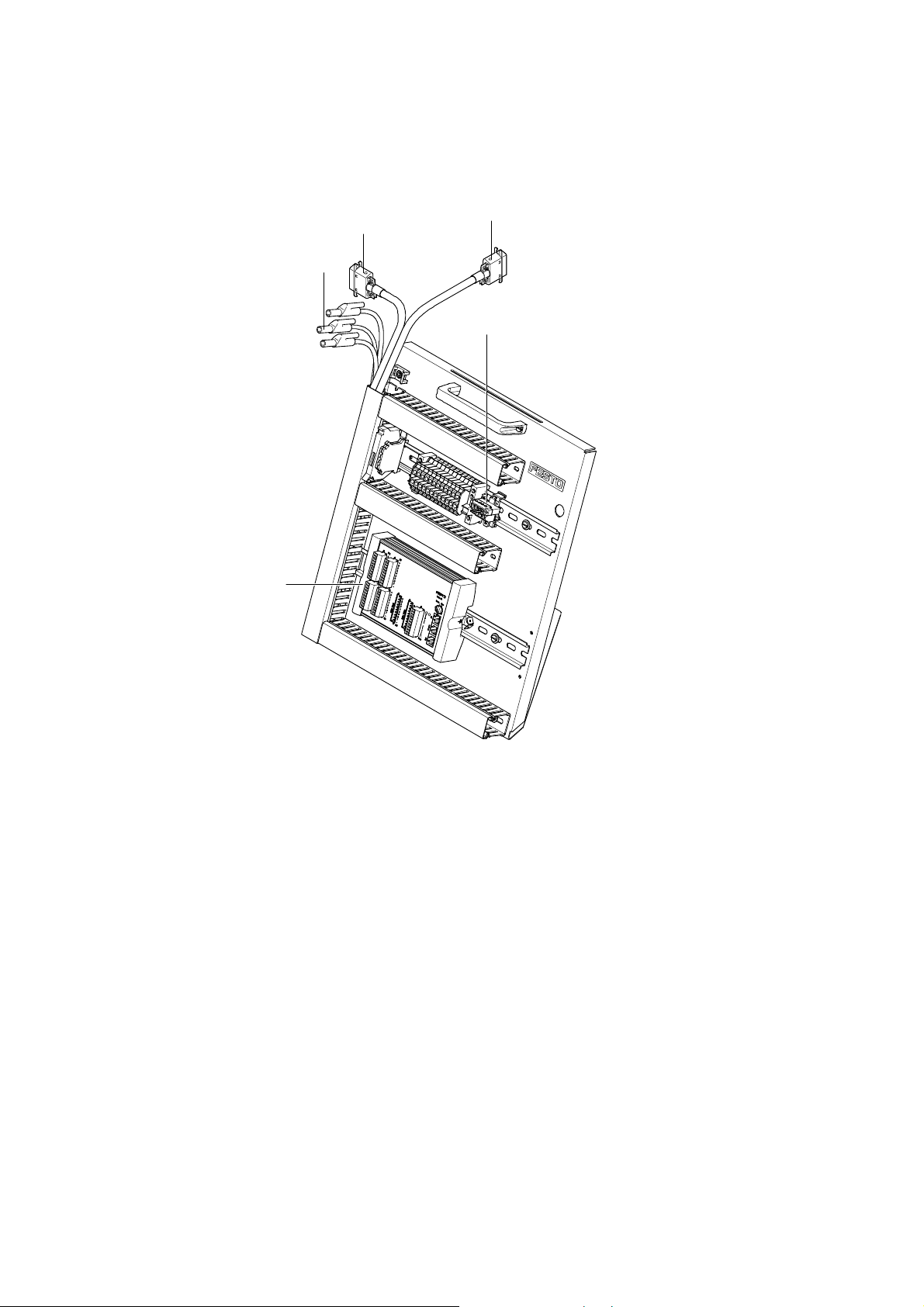
1 NOT-AUS mit gesteckter Brücke (XN)
2 CPU IPC FEC
®
Standard,Typ FC640
3 24 V-Anschlusskabel mit 4 mm Sicherheitsstecker
4 Anschlusskabel mit SysLink-Stecker zum Bedienpult (XMG1)
5 Anschlusskabel mit SysLink-Stecker zur Station (XMA2)
© Festo Didactic GmbH & Co. • 668858 7
Page 8

Aufbau und Funktion
Aus dem Baugruppenspektrum der IPC Reihe wurden bestimmte Module ausgewählt
und in das SPS-Board integriert. Damit lässt sich in gewissen Grenzen die
Modularität der IPCs auch auf das SPS-Board übertragen.
3.1
Lieferumfang
3.2
Zubehör
Das SPS-Board mit IPC FEC
®
Standard Typ FC640 besitzt:
• 32 x digitale Eingänge, 16 x digitale Ausgänge,
• 2 x serielle Schnittstellen,
• 1 x Ethernet 10 Base T Schnittstelle.
Das SPS-Board wird über RS 232 / Ethernet Schnittstelle mit dem PC verbunden und
mit der Programmiersoftware Festo FST programmiert.
Ein SPS-Board besteht aus:
• CPU IPC FEC
®
Standard Typ FC640
In unserem Produktkatalog finden Sie :
• Programmierkabel TLL-RS 232,
• Programmiersoftware,
• optionale Erweiterungsbaugruppen,
• Datenkabel,
• Dokumentation,
• Teachware.
8
© Festo Didactic GmbH & Co. • 668858
Page 9

Aufbau und Funktion
3.3
Anschluss externer Geräte
• Verbindung zu einer Prozesssimulation
Das SPS-Board kann mit einer Prozesssimulation kommunizieren (COSIMIR
EasyVeep). Das geschieht über die SysLink-Schnittstelle.
Für digitale Signale benötigen Sie:
– Interface EasyPort Best.-Nr. 167121,
– 2 x E/A-Datenkabel Best.-Nr. 167197.
Achtung
Materialschäden im EasyPort möglich, durch doppelte Spannungsversorgung.
Durch das E/A-Datenkabel wird das EasyPort mit Betriebsspannung versorgt.
Deshalb darf keine separate Spannungsversorgung angeschlossen werden.
• Die Simulationsbox
Sie simuliert Eingangssignale und zeigt Ausgangssignale der SPS an.
Für digitale Signale benötigen Sie:
– Simulationsbox, digital Best.-Nr. 170643 (ist direkt einsteckbar).
®
PLC,
Achtung
Materialschäden an der Simulationsbox möglich, durch doppelte
Spannungsversorgung.
Durch das E/A-Datenkabel wird die Simulationsbox mit Betriebsspannung versorgt.
Deshalb darf keine separate Spannungsversorgung angeschlossen werden.
© Festo Didactic GmbH & Co. • 668858 9
Page 10

Aufbau und Funktion
• Die Universalanschlusseinheit (SysLink) Best.-Nr. 162231 kann direkt am
SPS-Board, angeschlossen und Aktoren und Sensoren über 4 mm
Sicherheitsstecker verbunden werden.
•
Die Spannungsversorgung muss über eine externe 24 V DC-Quelle erfolgen. Dafür
bieten sich die Netzgeräte von Festo Didactic an, die als Einschubvariante für den
ER-Aufnahmerahmen oder als Tischvariante verfügbar sind.
3.4
Einbauweise
3.5
Ein-/Ausgänge
3.6
NOT-AUS Funktion
• Das SPS-Board besteht aus einem Metallwinkel auf dem die Steuerelemente und
Anschlussmöglichkeiten angebracht sind. Das SPS-Board steht im Wagen und
kann zur besseren Handhabung herausgenommen werden.
• Die digitalen Ein- und Ausgänge sind auf zwei SysLink-Stecker (IEEE 488)
verdrahtet. Die Pin-Belegung entspricht der SysLink-Schnittstelle des MPS
®
von
Festo Didactic.
• Der Stecker der NOT-AUS Klemme ist im Lieferzustand gebrückt. Somit sind die
digitalen Ausgänge mit Spannung versorgt. Wird die NOT-AUS Funktion
gewünscht, muss an diesem Stecker, anstatt der Brücke, das NOT-AUS Gerät
(Öffner) angeschlossen werden. Beim Betätigen des Öffners wird die
Spannungsversorgung der Ausgänge (Ausgangsbyte 0) unterbrochen.
(Die genaue Steckerbelegung ist aus den Kontaktbelegungstabellen in diesem
Handbuch ersichtlich.)
10
© Festo Didactic GmbH & Co. • 668858
Page 11
4. Inbetriebnahme mit MPS
®
4.1
Kabelverbindungen
2
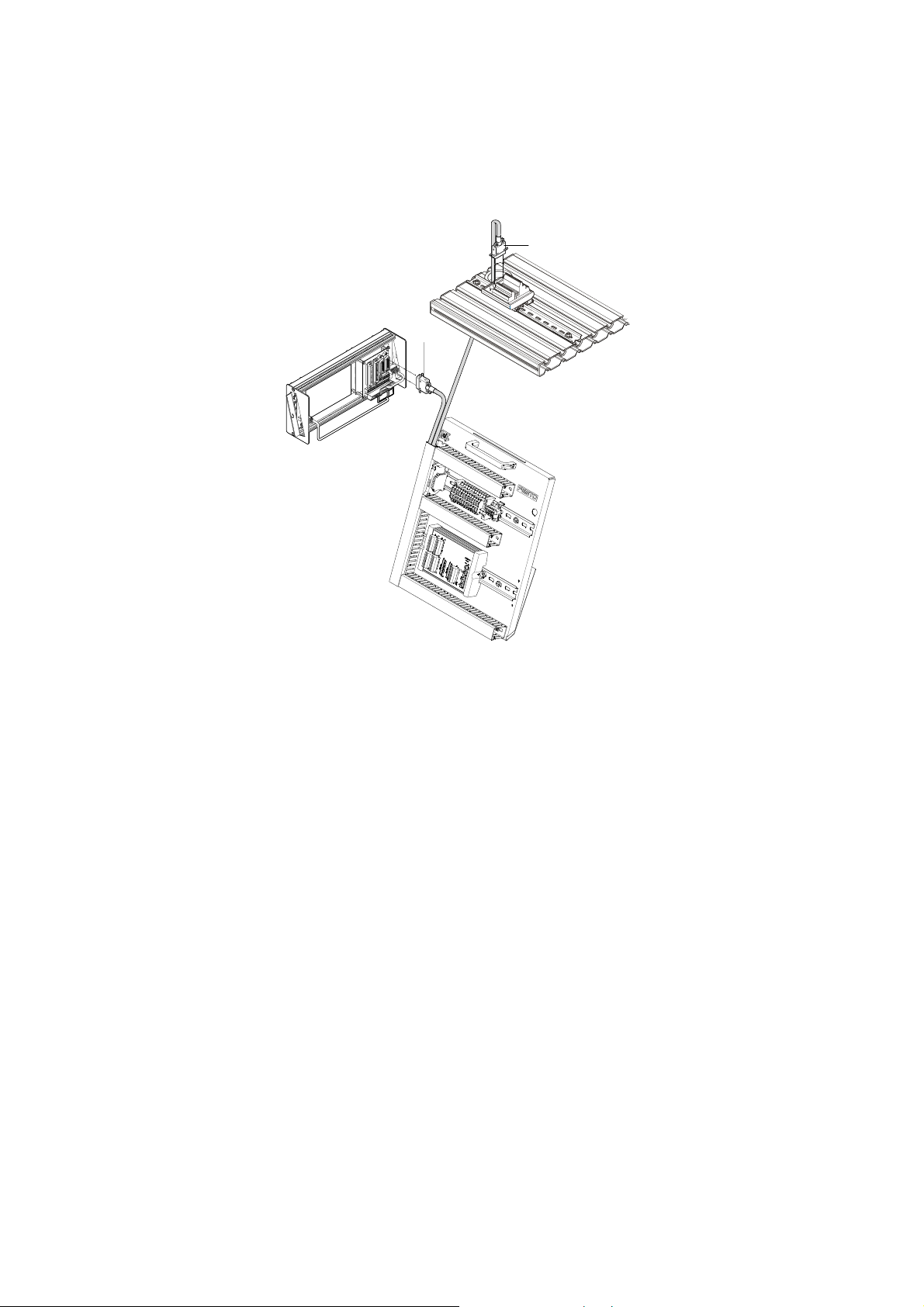
Kabelverbindungen zwischen SPS-Board, Bedienpult und Station
1
1. SPS Board – Station
Stecken Sie den Stecker XMA2 des SPS Boards in die Buchse XMA2 des
E/A-Terminals der Station.
2. SPS Board – Bedienpult
Stecken Sie den Stecker XMG1 des SPS Boards in die Buchse XMG1 des
Bedienpults.
3. SPS Board – Netzgerät
Stecken Sie die 4 mm Sicherheitsstecker in die Buchsen des Netzgerätes.
4. PC – SPS
Verbinden Sie Ihren PC durch ein Programmierkabel mit der SPS.
Achtung
Beachten Sie auch die Hinweise zur Inbetriebnahme im MPS
®
Stations-Handbuch!
© Festo Didactic GmbH & Co. • 668858 11
Page 12

Inbetriebnahme mit MPS®
12
© Festo Didactic GmbH & Co. • 668858
Page 13

5. Kontaktbelegungstabelle
5.1
Ein-/Ausgänge (digital)
Kontaktbelegung SPS-Board / Stecker
SPS-Board Stecker XMA2 SPS-Board Stecker XMG1 Digital
FC640 Adresse SysLink PIN FC640 Adresse Syslink PIN
OUT A 0.0 1 A 1.0 1
A 0.1 2 A 1.1 2
A 0.2 3 A 1.2 3
A 0.3 4 A 1.3 4
A 0.4 5 A 1.4 5
A 0.5 6 A 1.5 6
A 0.6 7 A 1.6 7
A 0.7 8 A 1.7 8
IN E 0.0 13 E 1.0 13
E 0.1 14 E 1.1 14
E 0.2 15 E 1.2 15
E 0.3 16 E 1.3 16
E 0.4 17 E 1.4 17
E 0.5 18 E 1.5 18 (NA 24V)
E 0.6 19 E 1.6 19
E 0.7 20 E 1.7 20
Versorgung 24 V 9,10,21,22 9,10,21,22
0 V 11,12,23,24 11,12,23,24
© Festo Didactic GmbH & Co. • 668858 13
Page 14

Kontaktbelegungstabelle
5.2
NOT-AUS Stecker/Klemme
Kontaktbelegung NOT-AUS Stecker NOT-AUS Klemme auf
SPS-Board (XN)
NOT-AUS 1 (gebrückt) 1 24 V
NOT-AUS 2 (gebrückt) 2 NA 24V (XMA2)
Kontakt Erweiterung 3 3 (gebrückt)
Kontakt Erweiterung 4 4 (gebrückt)
Hinweis
Das NOT-AUS -Signal wird zusätzlich auf E 1.5 (XMG1 Syslink) geführt!
14
© Festo Didactic GmbH & Co. • 668858
Page 15
6. Technische Daten
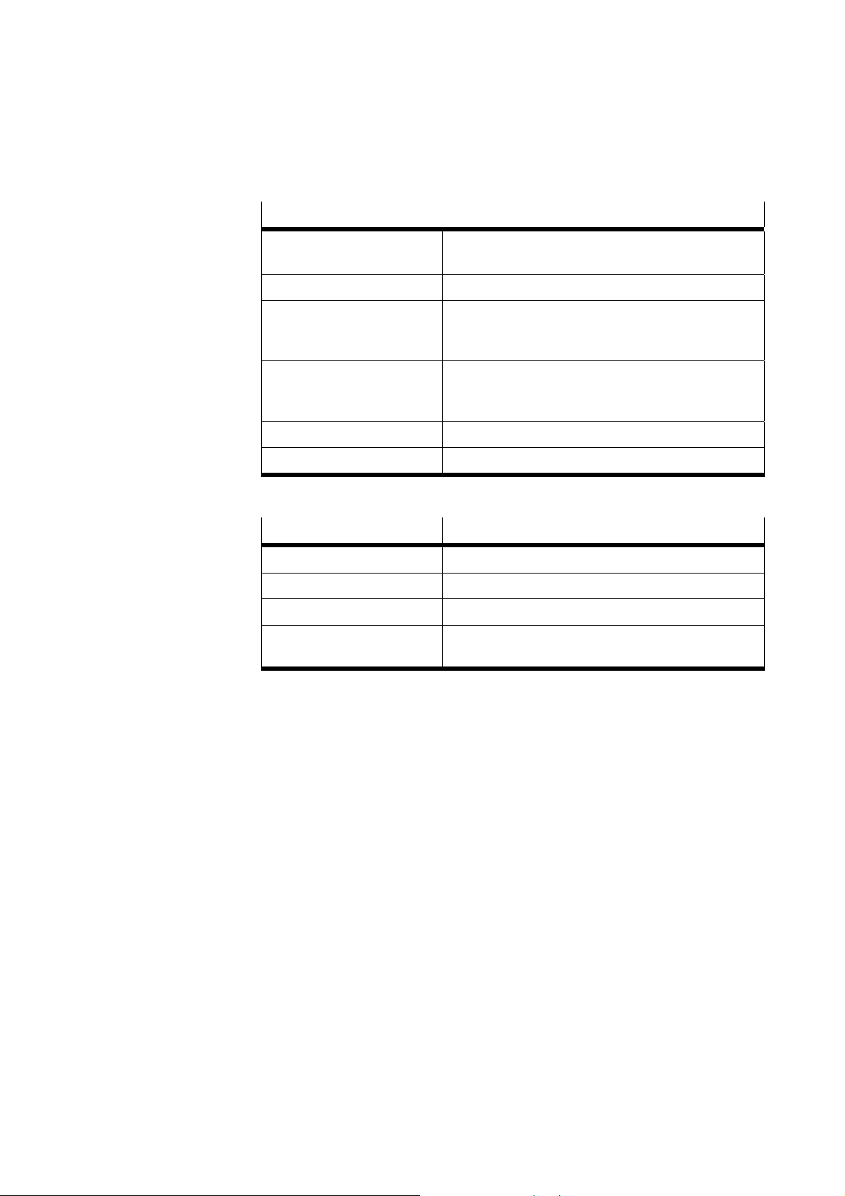
Technische Daten für alle Varianten des SPS-Boards
Betriebsspannung 24 V DC
(wird von externem Netzgerät geliefert)
Datensicherung
Schnittstellen SysLink Kabel für Anschluss Station,
Kabel für Anschluss Bedienpult
Brücke für NOT-AUS
Abmessungen Höhe 400 mm
Breite 340 mm
Tiefe 300 mm
Gewicht ca. 5 kg
Schutzart IP 20
Übersicht der Ausstattung CPU FEC-FC640-…
Arbeitsspeicher (kByte) 512
Digitale Eingänge 32
Digitale Ausgänge 16
Best.-Nr. 526875
© Festo Didactic GmbH & Co. • 668858 15
Page 16

Technische Daten
CPU FEC-FC640
Versorgungsspannung 24 V DC (20,4 – 30 V DC)
Leistungsaufnahme < 5 W
Gepufferte Echtzeituhr nein
Spannung/Strom (Eingang digital) 24 V DC / 5 mA
Verzögerungszeit 5 ms
2 schnelle Zählereingänge max. 2 kHz
Spannung/Strom (Ausgang
digital)
Maximaler Gruppenstrom
(Ausgang)
Maximale Schaltfrequenz
(Ausgang)
Merker / Zähler / Zeiten 10000 / 256 / 256
Arbeitsspeicher 512 kByte SRAM
Remanente Daten 30 kByte SRAM
Programmspeicherung 512 kByte in Flash-Speicher (Laufw. B: 500 kByte frei, Lese-
Programmierschnittstellen Serielle asynchrone TTL, RJ12 / Ethernet, RJ45
Netzwerkanschluss 10Base T, RJ45
24 V DC / max.400 mA
3,2 A
1 kHz
Schreibzugriff)
16
© Festo Didactic GmbH & Co. • 668858
Page 17

Anhang
Elektrische Schaltpläne
Die elektrischen Schaltpläne finden Sie am Ende dieses Handbuchs.
Zusätzlich finden Sie elektrische Schaltpläne zu den SPS Boards auf der “Technische
Unterlagen“ CD-ROM der MPS
®
Station(en) oder im Internet unter der Adresse:
http://www.festo-didactic.com/Service > MPS > Schaltpläne
© Festo Didactic GmbH & Co. • 668858 17
Page 18

Anhang
18
© Festo Didactic GmbH & Co. • 668858
Page 19

Contents
1. Introduction__________________________________________________ 21
2. Notes on safety _______________________________________________ 22
3. Design and function ___________________________________________ 23
3.1 Scope of delivery ______________________________________________ 24
3.2 Accessories __________________________________________________ 24
3.3 Connection of external equipment ________________________________ 25
3.4 Installation options ____________________________________________ 26
3.5 Inputs/outputs________________________________________________ 26
3.6 EMERGENCY STOP function______________________________________ 26
4. Commissioning with MPS
®
______________________________________ 27
4.1 Cable connections _____________________________________________ 27
5. Contact allocation table ________________________________________ 29
5.1 Inputs/outputs (digital)_________________________________________ 29
5.2 EMERGENCY STOP plug/terminal _________________________________ 30
6. Technical data ________________________________________________ 31
Appendix __________________________________________________________ 33
Electrical circuit diagrams _______________________________________ 33
© Festo Didactic GmbH & Co. • 668858 19
Page 20

Contents
20
© Festo Didactic GmbH & Co. • 668858
Page 21

1. Introduction
The IPC FEC® standard is a modular PLC system from Festo designed for industrial
use. It has been integrated into a didactic environment in the Festo Didactic Modular
Production System (MPS
®
) for use in vocational and further training.
The digital inputs and outputs are wired up to two SysLink plugs (IEEE 488). The pin
allocation corresponds to the SysLink interface of the MPS
®
of Festo Didactic.
© Festo Didactic GmbH & Co. • 668858 21
Page 22

2. Notes on safety
The PLC boards are designed according to state of the art technology and in
compliance with recognised safety regulations. However when using the system
there is nevertheless a risk of physical or fatal injury to the user or third parties or of
damage being caused to the machinery or other material assets.
The PLC boards are to be used only:
• for its intended purpose and
• in an absolutely safe conditions.
Faults impairing safety must be rectified immediately!
For your own safety please follow the safety notes below:
General
• Trainees must only work on the PLC board under the supervision of an instructor.
Electrics
• Electrical connections are to be wired up only when power is disconnected!
• Electrical connections are to be disconnected only when power is disconnected!
• Use only low voltages of up to 24 V DC.
22
© Festo Didactic GmbH & Co. • 668858
Page 23
3. Design and function
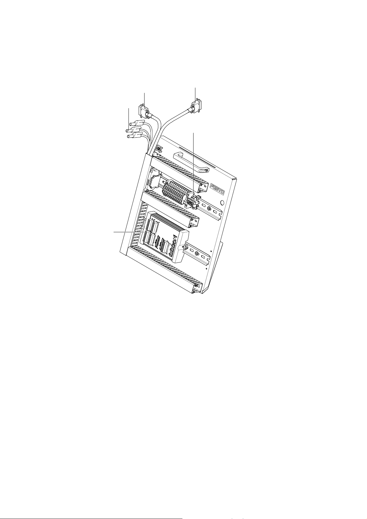
4
3
2
5
1
1 EMERGENCY STOP with slotted jumper (XN)
2 CPU IPC FEC
®
standard,type FC640
3 24 V connecting cable with 4 mm safety plugs
4 Connecting cable with SysLink plug to the control console (XMG1)
5 Connecting cable with SysLink plug to the station (XMA2)
© Festo Didactic GmbH & Co. • 668858 23
Page 24

Design and function
Specific modules have been selected from the module spectrum of the IPC FEC®
standard series and integrated into the PLC boards and with that the modularity of
the PLC can to some extent also be transferred to the PLC board.
3.1
Scope of delivery
3.2
Accessories
The PLC Board IPC FEC
®
Standard, type FC640 consists of:
• 32 x digital inputs and 16 x digital outputs,
• 2 x seriell interfaces,
• 1 x Ethernet 10 Base T interface.
The PLC is connected to the PC via RS 232 / Ethernet interface on the CPU and
programmed using the FST software.
The IPC FEC
• CPU IPC FEC
®
standard consists of:
®
Standard, type FC640
In our product catalogue you will find:
• Programming cable TLL-RS 232,
• Programming software,
• optional extension modules,
• Data cables,
• Documetation,
• Courseware.
24
© Festo Didactic GmbH & Co. • 668858
Page 25

Design and function
3.3
Connection of external
equipment
• Connection to a process simulation
The PLC board can communicate with a process simulation (COSIMIR
EasyVeep) via the SysLink interface.
For digital signals you need:
– The Interface EasyPort, Order No. 167121,
– 2x I/O data cable (crossed), Order No. 167197.
®
PLC,
Attention
The EasyPort must not be connected to a separate voltage if the I/O data cable is
used. The voltage supply to the EasyPort is effected via the cable.
• The simulation box
It generates binary input signals and displays binary output signals of the PLC.
For digital signals you need:
– Digital simulation box, Order No. 170643.
Attention
The simulation box does not need to be connected to a separate voltage supply if
this cable is used, since the voltage supply from the PLC board is effected via that
cable.
• The universal terminal unit (SysLink) Order No. 162231, equipped with the same
interface, can be connected via the cable Order No. 034031, and the actuators
and sensors connected via 4 mm fail-safe plug.
The voltage supply must be effected via an external 24 V DC source. The power
supply units from Festo Didactic are suitable for this and are available in the form of
a function card variant for the ER-cabinet frames or in the form of a table variant.
© Festo Didactic GmbH & Co. • 668858 25
Page 26

Design and function
3.4
Installation options
3.5
Inputs/outputs
3.6
EMERGENCY STOP function
• Controller, terminals, cable ducts and rails are mounted on a metal bracket. the
PLC board is suspended in the trolley. The PLC board can be simply removed
from the trolley and placed on a table when working on the PLC board or for
demonstration purposes.
• The digital inputs and outputs are wired up to two SysLink plugs (IEEE 488). The
pin allocation corresponds to the SysLink interface of the MPS
®
from Festo
Didactic.
• The two sockets marked with EMERGENCY-STOP are bridged with the short-
circuit plug provided in order to provide the voltage supply to the digital outputs.
If the EMERGENCY-STOP function is wanted, then the EMERGENCY-STOP device
(normally closed contact) must be connected to these sockets. The voltage
supply of the outputs (output byte 0) is interrupted if this normally closed
contact is actuated.
(The precise plug allocation can be found in the contact allocation tables of this
document.)
26
© Festo Didactic GmbH & Co. • 668858
Page 27
4. Commissioning with MPS
®
4.1
Cable connections
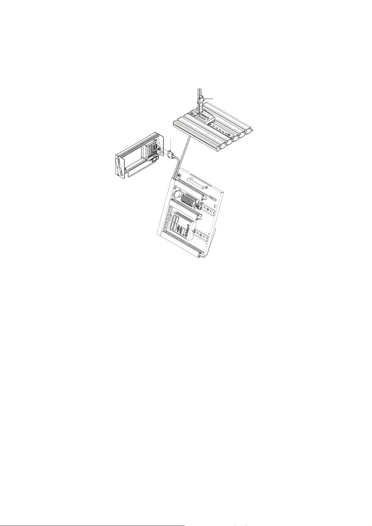
2
Cable connections from PLC board to control console and station
1
1. PLC board – station
Plug the XMA2 plug of the PLC board into the XMA2 socket of the I/O terminal of
the station.
2. PLC board – control console
Plug the XMG1 plug of the PLC board into the XMG1 socket of the control
console.
3. PLC board – power supply unit
Plug the 4 mm safety plugs into the sockets of the power supply unit.
4. PC – PLC
Connect your PC to the PLC by means of a programming cable.
Attention
Observe the notes for commissioning in the MPS
®
station manual!
© Festo Didactic GmbH & Co. • 668858 27
Page 28

Commissioning with MPS®
28
© Festo Didactic GmbH & Co. • 668858
Page 29

5. Contact allocation table
5.1
Inputs/outputs (digital)
Contact allocation PLC-board / plug
PLC-board plug XMA2 PLC-board plug XMG1 Digital
FC640 adress SysLink PIN FC640 adress Syslink PIN
OUT A 0.0 1 A 1.0 1
A 0.1 2 A 1.1 2
A 0.2 3 A 1.2 3
A 0.3 4 A 1.3 4
A 0.4 5 A 1.4 5
A 0.5 6 A 1.5 6
A 0.6 7 A 1.6 7
A 0.7 8 A 1.7 8
IN E 0.0 13 E 1.0 13
E 0.1 14 E 1.1 14
E 0.2 15 E 1.2 15
E 0.3 16 E 1.3 16
E 0.4 17 E 1.4 17
E 0.5 18 E 1.5 18 (NA 24V)
E 0.6 19 E 1.6 19
E 0.7 20 E 1.7 20
Supply 24 V 9,10,21,22 9,10,21,22
0 V 11,12,23,24 11,12,23,24
© Festo Didactic GmbH & Co. • 668858 29
Page 30

Contact allocation table
5.2
EMERGENCY STOP
plug/terminal
Contact allocation EMERGENCY-STOP plug EMERGENCY-STOP terminal at the
PLC board (XN)
EMERGENCY-STOP 1 (bridged) 1 24 V
EMERGENCY-STOP 2 (bridged) 2 NA 24V (XMA2)
contact extension 3 3 (bridged)
contact extension 4 4 (bridged)
Note
The Emergency-Stop signal additionally is connected to E 1.5 (XMG1 Syslink)!
30
© Festo Didactic GmbH & Co. • 668858
Page 31
6. Technical data
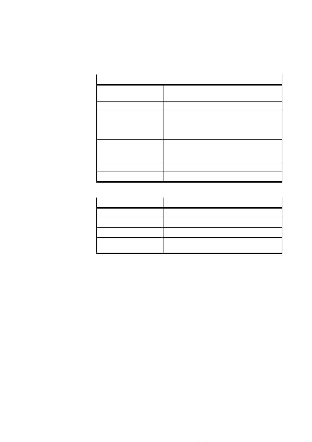
Technical data for all PLC boards
Operating voltage 24 V DC
(supplied by an external power supply unit)
Data backup
SysLink interfaces 1 x cable for connection to station
1 x cable for connection to console
1 x strap for connection to EMERGENCY-STOP
Dimensions Height 400 mm
Width 340 mm
Depth 300 mm
Weight Approx. 5 kg
Protection classification IP 20
Overview of equipment CPU FEC-FC640
Main memory (kByte) 512
Digital inputs 32
Digital outputs 16
Order No. 526875
© Festo Didactic GmbH & Co. • 668858 31
Page 32

Technical data
CPU FEC-FC640
Supply voltage 24 V DC (20,4 – 30 V DC)
Power consumption < 5 W
Buffered real time clock no
Input voltage/ current (digital) 24 V DC / 5 mA
Input signal delay 5 ms
2 high-speed inputs max. 2 kHz
Output voltage/ current (digital) 24 V DC / max.400 mA
Maximum group current (outputs) 3,2 A
Maximum switching speed
(outputs)
Flags / Counters / Timers 10000 / 256 / 256
Main Memory 512 kByte SRAM
Remanent data 30 kByte SRAM
Buffering 512 kByte in the flash-memory (drive B: 500 kByte free,
Programming interfaces serial asynchronous TTL, RJ12 / Ethernet, RJ45
Network interface 10Base T, RJ45
1 kHz
reading- writing access)
32
© Festo Didactic GmbH & Co. • 668858
Page 33

Appendix
Electrical circuit diagrams
Electrical circuit diagrams please find at the end of this manual.
Additionally electrical circuit diagrams for the PLC boards can be found on the
“Technical details” CD-ROM of the MPS
®
station(s) or in internet at the address:
http://www.festo-didactic.com / Service > MPS > Circuit diagrams
© Festo Didactic GmbH & Co. • 668858 33
Page 34

Appendix
34
© Festo Didactic GmbH & Co. • 668858
 Loading...