

Page 1
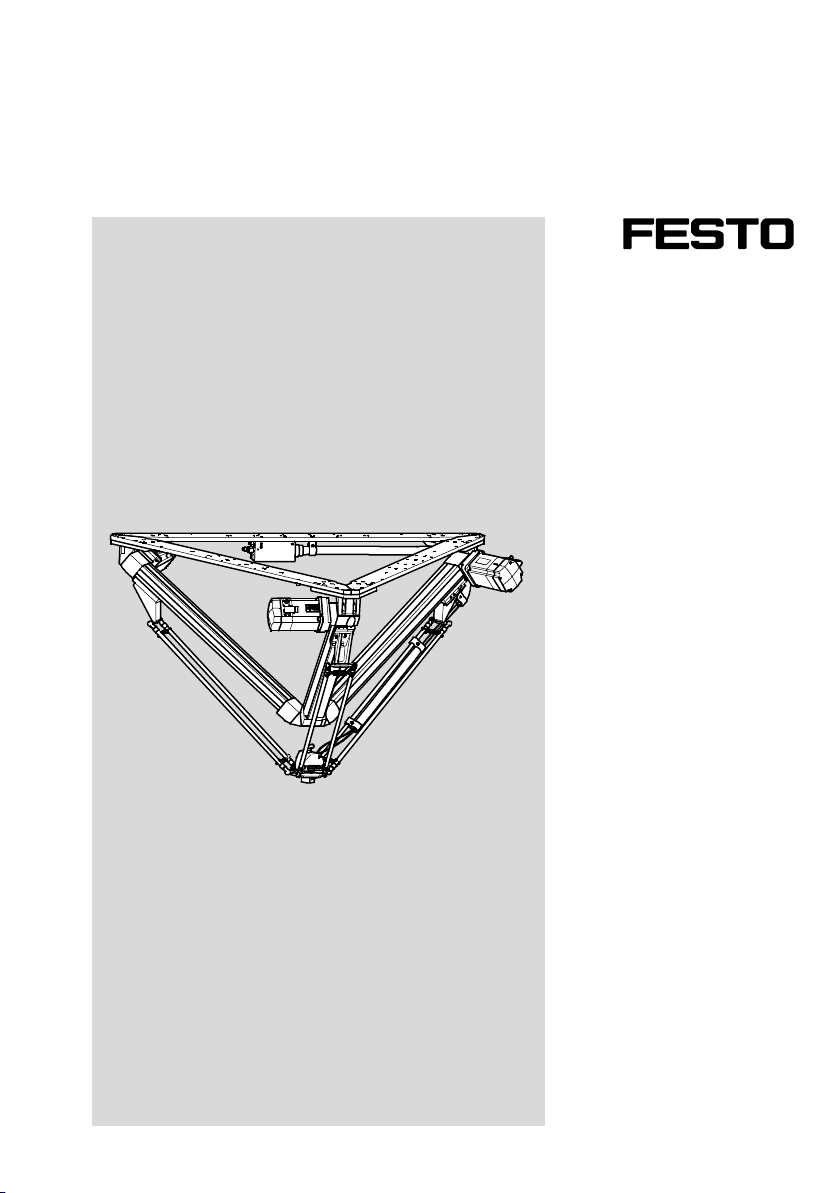
Tripod kinematics
EXPT
Description
Mechanical assembly
8003784
1204a
Page 2
EXPT
Translation of the original instructions
GDCP-EXPT-KM-KOMP-EN
®
CoDeSys
is a re gistered trademark of its respe ctive trademark holder in certain countries.
Identificationof hazards and instructions on how to prevent them:
War ning
Hazards that can cause death or serious injuries.
Caution
Hazards that can cause minor injuries or serious material damage.
Other symbols:
Note
Material damage or loss of function.
Recommendations, tips, references to other documentation.
Essential or useful accessories.
Information on environmentally sound usage.
Text designations:
• Activities that may be carried out in any order.
1. Activities that should be carried out in the order stated.
– General lists.
2 Festo – GDCP-EXPT-KM-KOMP-EN – 1204a –
Page 3

EXPT
Table of Contents – EXPT
1 Safety and requirements for product use 5......................................
1.1 Safety 5..................................................................
1.1.1 General safety regulations 5..........................................
1.1.2 Intended use 5.....................................................
1.2 Safety conditions 6.........................................................
1.2.1 Technical requirements 6............................................
1.2.2 Qualification of trained personnel 6....................................
1.2.3 Areas of application and approval by authorities 6........................
2Overview 7................................................................
2.1 Features 7................................................................
2.2 Function and application 9....................................................
2.3 Overview of interfaces 9.....................................................
2.4 Control elements and connections 10............................................
3 Assembly and installation 11..................................................
3.1 Transport 11................................................................
3.2 Storage conditions 11........................................................
3.3 Unpacking 12...............................................................
3.4 Checking tripod kinematics and scope of delivery 13................................
3.5 Preparations for assembly 14..................................................
3.5.1 Dimensions 14......................................................
3.5.2 Requirements for the assembly site 14..................................
3.6 Assembly on a frame 15.......................................................
3.7 Mountingoptions 16.........................................................
3.7.1 Direct mounting with screws 16........................................
3.7.2 Mounting with slot nuts 17............................................
3.8 Preparing tripod kinematics for mounting 19......................................
3.9 Mountingof attac hments 23...................................................
3.9.1 Attachment for EXPT-...-T0 23..........................................
3.9.2 Attachment for EXPT-...-T1 to T4 23.....................................
3.10 Installation 24..............................................................
3.10.1 Overview 24........................................................
3.10.2 Overview of connections 25...........................................
3.10.3 Connect compressed air 25............................................
3.10.4 Installing motor cables and sensor cable 25..............................
3.10.5 Earthing 27........................................................
Festo – GDCP-EXPT-KM-KOMP-EN – 1204a – English 3
Page 4

EXPT
4 Commissioning 28...........................................................
5 Operation and diagnostics 29..................................................
5.1 Maintenance and care 29......................................................
5.2 Troubleshooting 31..........................................................
6 Disassembly and repair 32....................................................
6.1 Dismantling 32..............................................................
6.1.1 Dismounting the tripod kinematics from the frame 32.......................
6.1.2 Dismounting motors 35...............................................
6.1.3 Dismounting the front unit 36..........................................
6.1.4 Dismantling the protective conduit 38...................................
6.1.5 Dismounting a pair of rods 39..........................................
6.2 Repair 40..................................................................
6.3 Accessories 40..............................................................
6.4 Disposal 40................................................................
A Technical appendix 41........................................................
A.1 Technical data for tripod kinematics EXPT-...-T0 to T4 41.............................
A.1.1 General 41.........................................................
A.1.2 Mechanical 41......................................................
A.1.3 Dynamic 42........................................................
A.1.4 Operating and environmental conditions 42...............................
A.2 Technical data of front unit for EXPT-...-T1 to T4 43.................................
A.2.1 General 43.........................................................
A.2.2 Mechanical 43......................................................
A.2.3 Electrical 43........................................................
4 Festo – GDCP-EXPT-KM-KOMP-EN – 1204a – English
Page 5
1 Safety and requirements for product use
1 Safety and requirements for product use
1.1 Safety
1.1.1 General safety regulations
• Follow the general safety instructions in the relevant chapters.
Specific safety instructions can be found immediately before the task instructions.
1.1.2 Intended use
The EXPT tripod kinematics are intended for installation in machines and automation systems and are
to be used as follows:
– in excellent technical condition
– in original status without unauthorised modifications
– within the limits of the product defined by the technical data ( Appendix A.1)
– in a n industrial environment.
Note
The removal of mechanical components (e.g. motor, axis, pair of rods) c auses
referencing to be lost and thus results in a reduction in absolute positioning accuracy.
When commissioning, referencing or calibration must be carried out again.
Note
In the event of damage caused by unauthorised manipulation or other than intended
use, the guarantee is invalidated and the manufacturer is not liable for damages.
Festo – GDCP-EXPT-KM-KOMP-EN – 1204a – English 5
Page 6

1 Safety and requirements for product use
1.2 Safety conditions
• Make this documentation available to the design engineer, installer and personnel responsible for
commissioning the machine or system in which this product is used.
• Make sure that the specifications of the documentation are always complied with. Also read and
follow all accompanying documentation and the documentation for any associated accessories.
• Take into considerationthe legal regulations applicable for the destination, as well as:
– regulations and standards
– regulations of the testing organizations and insurers
– national specifications.
1.2.1 Technical requirements
• All warnings and instructions in th is documentation for the correct and safe use of the product must
be obser ved at all times.
• Comply with the connection and environmentalconditions of the product ( Appendix A.1) and all
connected components.
Only compliance with the limit values or load limits permits operation of the product in accordance
with the relevant safety regulations.
1.2.2 Qualification of trained personnel
The product should only be installed by properly trained personnel in accordance with these instructions. The trained personnel must be must be familiar with:
– the applicable regulations on accident protection and industrial safety, and
– the documentation for the product.
1.2.3 Areas of application and approval by authorities
Standards and test values, which the product complies with and fulfils, can be found in the “Technical
data” section ( Appendix A.1).
6 Festo – GDCP-EXPT-KM-KOMP-EN – 1204a – English
Page 7

2Overview
2Overview
2.1 Features
Tripod kinematics feature Code Specification
Working space –45 ∅ 450 mm, height 100 mm
–70 ∅ 700 mm, height 100 mm
–90 ∅ 900 mm, height 100 mm
– 120 ∅ 120 mm, height 100 mm
Attachment components –T0 Front unit without attachment component
–T1 Front unit with rotary drive, size 8
–T2 Front unit with rotary drive, size 8, and pneumatic
rotary through-feed
–T3 Front unit with rotary drive, size 11
–T4 Front unit with rotary drive, size 11, and pneumatic
rotary through-feed
Motor attachment position
( Fig. 3.12)
Particle protection Standard
Tab. 2 . 1
– HHH Motor axis A1, A2, A3 rear
–HHV Motor axis A1 rear
Motor axis A2 rear
Motor axis A3 front
–HVH Motor axis A1 rear
Motor axis A2 front
Motor axis A3 rear
–HVV Motor axis A1 rear
Motor axis A2 front
Motor axis A3 front
–VHH Motor axis A1 front
Motor axis A2 rear
Motor axis A3 rear
–VHV Motor axis A1 front
Motor axis A2 rear
Motor axis A3 front
– VVH Motor axis A1 front
Motor axis A2 front
Motor axis A3 rear
– VVV Motor axis A1, A2, A3 front
–P Protected version
Festo – GDCP-EXPT-KM-KOMP-EN – 1204a – English 7
Page 8
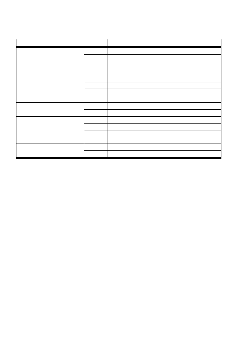
2Overview
Accessories feature Code Specification
Control system Without control system
–C Control system on a mounting plate for installation in a
control cabinet
–CC Complete control system with control cabinet
Multi-axis controller Without control system
–C1 Control system with multi-axis controller CMXR-C1
–C2 Control system with multi-axis controller CMXR-C2 and
integrated PLC
Operator terminal Without operator unit
–B With operator unit CDSA
Cable length No cables or tubing included
–5 Connecting cable and 5 m long tubing included
–10 Connecting cable and 10 m long tubing included
–15 Connecting cable and 15 m long tubing included
Calibration Standard
–S With calibration
Tab. 2 . 2
8 Festo – GDCP-EXPT-KM-KOMP-EN – 1204a – English
Page 9
2Overview
2.2 Function and application
The E XPT is a tripod kinematics unit with three ser vo motors, each powering a toothed belt axis. The
linear movements of the axes are transferred to the front unit by the principle of parallel kinematics.
A rotary drive is mounted on the front unit for variants T1 to T4. Suction cups or grippers can either be
attached to these directly or via the corresponding adapter kits. In addition, variants T2 and T4 are also
equipped with a pneumatic rotary through-feed for an air connection.
Variant P8 with particle protection is functionally identical to the other variants. The only difference
being that the axes are rotated by 180° and the toothed belt faces upwards. This prevents abrasion in
the working space.
The optional control system includes a higher-order multi-axis controller. This controls the interplay of
movements for the three motor controllers.
The EXPT tripod kinematics are intended for installation in machines and automation systems.
2.3 Overview of interfaces
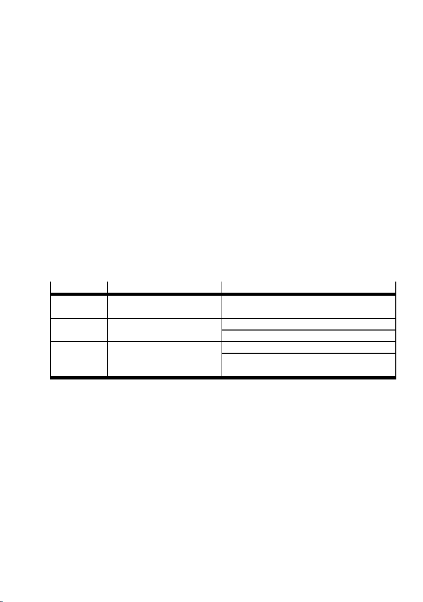
Interface Documentation Description
Motors Accompanying user manual
for the motors
Pneumatic
components
Sensors Chapter 3.10. Sensor connection for rod loss detection
Tab. 2 . 3
Chapter 3.10. Compressed air supply for rod loss detection
Connections of the motors
Air supply for actuators (T2 and T4)
Sensor connection for position sensing of the
rotary drive on the front unit (T1 to T4)
Festo – GDCP-EXPT-KM-KOMP-EN – 1204a – English 9
Page 10
2Overview
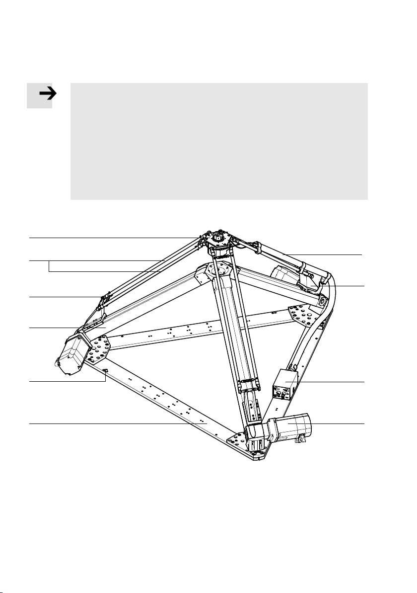
2.4 Control elements and connections
Note
The attachment position of the motors will vary according to the configuration of the
tripod kinematics and depends on the order code ( www.festo.com/catalogue).
• Be mindful of the following during assembly and installation:
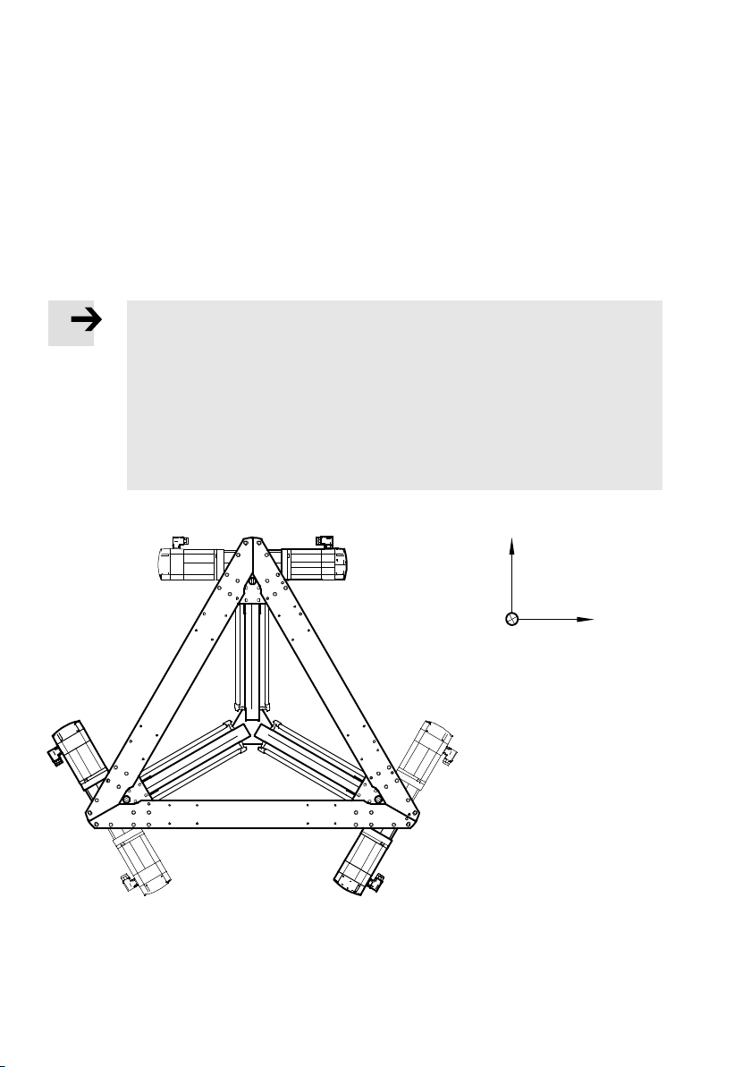
– the motor attachment position ( Fig. 3.12).
The illustrated variant is an example and corresponds to the variant T1 to T4 with
rotary drive and motors in attachment position HH H.
– the position of the electrical and pneumatic connections.
The interface housing is located opposite the motor of axis 1 on the mounting
frame.
The E XPT has the following components, connections and display components:
1
2
3
4
5
6 7
1 Front unit
(Variant T1 to T4 with rotary drive)
2 Rod pair
3 Joint
4 Toothed belt axis
5 EarthconnectionM6(6x)
Fig. 2.1
6 Mounting frame
7 Motor (standard alignment HHH)
8 Interface housing
9 Manifold block (different for variant P8)
aJ Protective conduit
aJ
9
8
10 Festo – GDCP-EXPT-KM-KOMP-EN – 1204a – English
Page 11
3 Assembly and installation
3 Assembly and installation
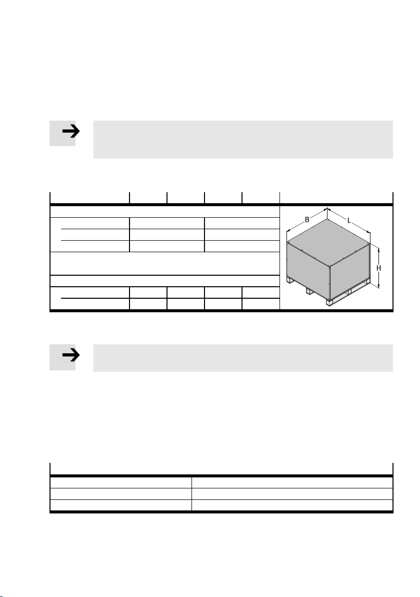
3.1 Transport
Note
• Always transport the tripod kinematics lying on the mounting frame 6 ( Fig. 2.1)
(delivery status).
When delivered, the tripod kinematics are lying on the mounting frame, bolted to the pallet and packed
in a box.
EXPT
Dimensions [mm]
H 1090 1320
L 1725 1925
B 1425 1725
Weight [ kg]
Tri po d k in em atics 45 47.5 61.5 66
Total w e igh t
1) With max. accessories
Tab. 3 . 1
45 70 95 120
1)
165 170 220 225
Note
• For transport, observe the marking on the upper side of the transport box.
1. Transport the packed tripod kinematics to the prepared installationsite on the pallet.
2. Set down the pallet on a stable, flat ground or base as close as possible to the installation site.
3.2 Storage conditions
If the tripod kinematics are not assembled immediately, they must be stored under the following conditions.
Storage conditions
Storage temperature [°C] –10 … +60
Maximum storage period 60 months
Requirements of storage location Dry, stable and flat
Tab. 3 . 2
Festo – GDCP-EXPT-KM-KOMP-EN – 1204a – English 11
Page 12
3 Assembly and installation
3.3 Unpacking
Note
Damage to the product from incorrect handling.
• To unpack, set down the pallet on a stable, flat ground or base as close as possible
to the installation site.
• Have ready an appropriate triple square screwdriver to undo the screws.
• Make sure that packaging parts cannot fall onto the tripod kinematics.
• Keep the packaging for later use or dispose of it in the proper manner.
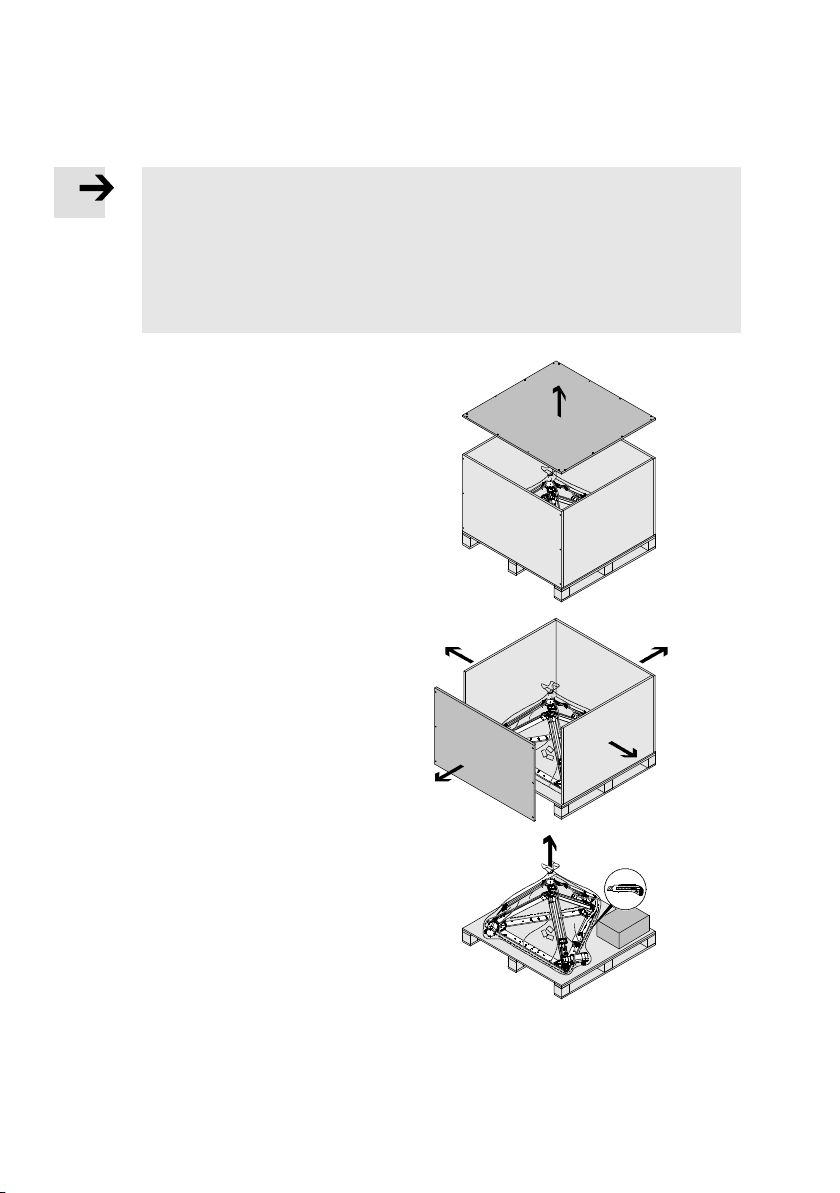
Removing transport packaging
1. Remove the four screws of the lid and lift the
lid up and off the transport box.
2. Remove all screws from the side walls and
remove them.
Start with one of the long sides.
As you do so, secure the other side walls to
make sure they do not fall over.
3. Remove the transparency. Do this by using an
appropriate tool to cut the transparency
parallel to the contour of the product. When
cutting, make sure that you do not damage or
scratch the tripod kinematics. Then pull the
transparency up and away from the product.
Fig. 3.1
12 Festo – GDCP-EXPT-KM-KOMP-EN – 1204a – English
Page 13
3 Assembly and installation
3.4 Checking tripod kinematics and scope of delivery
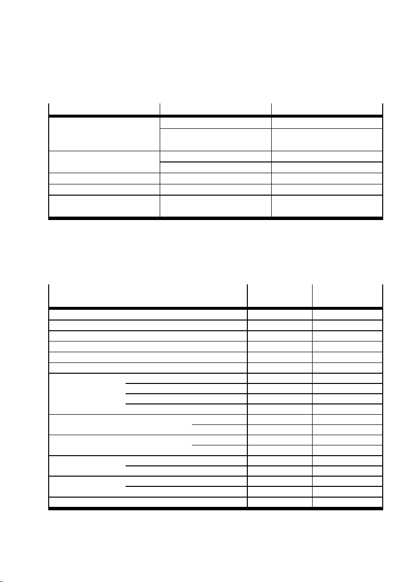
1. After unpacking, check the following parts:
Checking
Rod pair broken or damaged replace
Compressed air/supply air hose damaged replace
Protective conduit damaged replace
Mounting clip damaged replace
Electrical or pneumatic
connection
1) ( www.festo.com/spareparts)
Tab. 3 . 3
2. Open t he accessories box fastened to the pallet and remove its contents.
3. Remove the mounting screw in the box and remove the box from the pallet.
4. Check that the delivery is c omplete.
Designation
Description of tripod kinematics 1 1
Washer for oblong hole 6 6
Spacer for referencing the axes 1 1
USB memory card 1 1
Lubricating grease LUB-KC1 1 1
User manual for motor Kinematics 1 1
Assembly
instructions
Axial kit Kinematics 1 1
Motor cable Kinematics 1
Encoder cable Kinematics 1
Front unit with rotary drive – 1
Motor cable Kinematics 3
Encoder cable Kinematics 3
Sensor cable Pressure switch 1
Position detection for rotary drive – 1
Tubing Rod loss detection 1 1
Rotary drive air – 11)(T2 and T4 only)
Inscription label for cables 3x2
1) Optional
Tab. 3 . 4
Possible defect Remedy
1)
detached from the joint
install ( Chapter 6.1.5)
( Fig. 2.1)
1)
disconnected from the por t re-connect
1)
1)
damaged replace
1)
Number for
EXPT-...-T0
1)
1)
1)
Rotary drives – 1
1)
Rotary drives – 1
1)
1)
Number for
EXPT-...-T1 to T4
1)
1
1)
1
1)
3
1)
1)
3
1)
1)
1
1)
1)
4x2
Festo – GDCP-EXPT-KM-KOMP-EN – 1204a – English 13
Page 14
3 Assembly and installation
3.5 Preparations for assembly
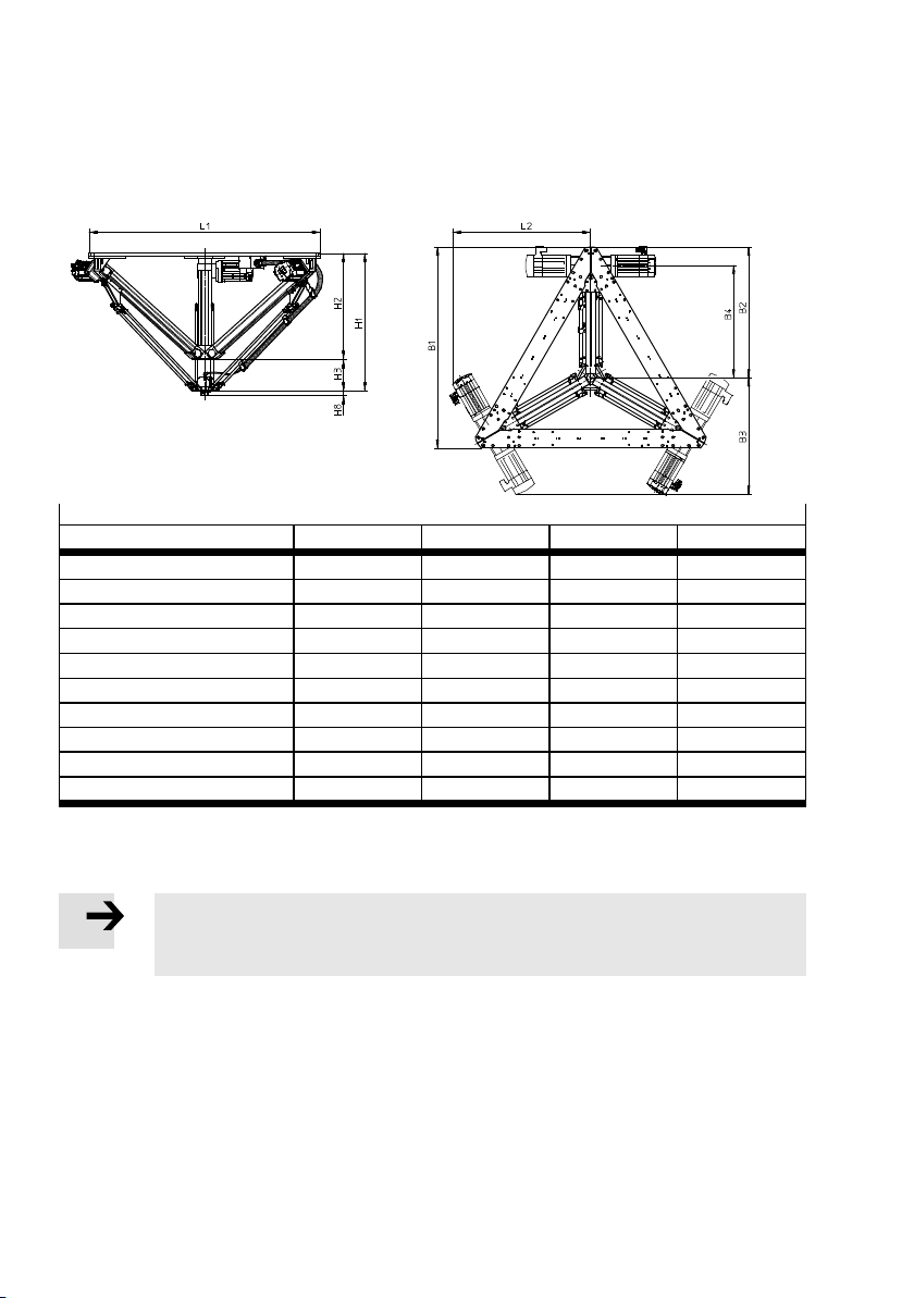
3.5.1 Dimensions
Dimensions [mm]
EXPT 45 70 95 120
B1 947 1077 1213 1355
B2 617 703 794 888
B3 549 590 626 672
B4 530 622 705 800
H1 659 727 827 944
H2 493 561 636 710
H3 166 166 191 234
H8 (for E XPT-...-T1 to T4 only) 27 27 27 27
L1 1088 1238 1394 1558
L2 652 727 803 885
Tab. 3 . 5
3.5.2 Requirements for the assembly site
Note
• Observe the catalogue specifications for the exac t positioning of the mounting holes
( www.festo.com/catalogue).
The following conditions must be met, otherwise the range of functions may be restricted:
– enough room for the tripod kinematics to move, including room outside the working space
(see catalogue specifications regarding obstructions www.festo.com/catalogue)
– torsionally rigid, tension-free suspension of the tripod kinematics
– flat bearing surface at the mounting corners
– adequate mounting to absorb the maximum forces ( www.festo.com/catalogue)
– allowance made for the affects of mass and rigidity on positioning accuracy and path accuracy
– adherence to the catalogue specifications for vibration limits, permissible forces and torques
( www.festo.com/catalogue).
14 Festo – GDCP-EXPT-KM-KOMP-EN – 1204a – English
Page 15
3 Assembly and installation
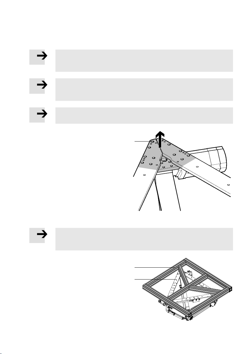
3.6 Assembly on a frame
Note
The frame is not included in the scope of delivery. Installation varies according to the
design of t he frame.
Note
If the oblong holes 1 are used, the bea ring surface of the screws is too small.
• Use the accompanying washers with the screws. ( Fig. 3.2).
Note
• Use screws with strength class of at least 8.8.
The tripod kinematics must be fastened to a
frame only in the area of the corner bracket of the
mounting frame. There must be a torsionally rigid,
flat bearing surface in the area of the corner
bracket. In order for the tripod kinematics to
attain the positioning accuracy stated in the technical data, the following minimum requirements
apply to the bearing surface:
– flatness = 0.05 mm
– parallelism = 0.5 mm.
Other holes can be used only as an assembly aid
or for fastening additional installation elements
such as cable ducts.
Note
Deviations from the minimum requirements lead to increased wear and/or inaccuracies
in positioning during later operation.
1
Fig. 3.2
1
2
1 Frame with reinforcements (example)
2 Mounting frame of tripod kinematics
Festo – GDCP-EXPT-KM-KOMP-EN – 1204a – English 15
Fig. 3.3
Page 16
3 Assembly and installation
3.7 Mounting options
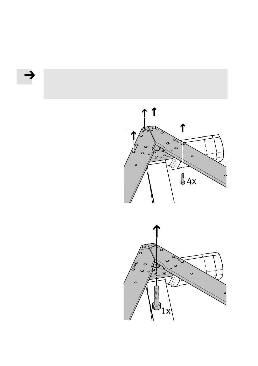
3.7.1 Direct mounting with screws
Note
Removing a motor causes the referencing of the corresponding axis to be lost. When
commissioning, the axis must be referenced again.
• If possible, use mounting holes which do not require the motor to be removed.
Screws M8 to DIN 912
Direct mounting with at least 4 screws per corner
bracket directly on the frame
(dimensions catalogue specifications).
These 4 screws should be placed far enough
apart to ensure a torsionally rigid connection.
If the oblong holes 1 are used, use the accompanying washers.
1
Fig. 3.4
Screws M20 to DIN 912
Direct mounting with one screw per corner
bracket directly on the frame.
There is a central hole for this purpose on every
corner.
• Make sure t hat the bearing surface is in the
area of the corner bracket.
Fig. 3.5
16 Festo – GDCP-EXPT-KM-KOMP-EN – 1204a – English
Page 17
3 Assembly and installation
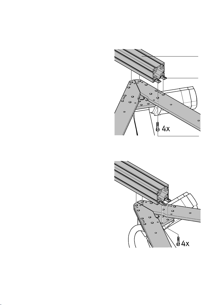
3.7.2 Mounting with slot nuts
Slot nut mounting parallel to mounting frame
Example 1
The holes in the corner brackets are arranged so
that a 80x80 profile 1 with 40 mm between slots
can be fastened in a number of different positions.
1 Profile (e.g. HMBS-80/80)
2 Slot nut (e.g. NST-HMV-8-2-M8)
3 Screw ( e.g. M8x35 DIN 912 )
Fig. 3.6
Example 2
1
2
3
Fig. 3.7
Festo – GDCP-EXPT-KM-KOMP-EN – 1204a – English 17
Page 18
3 Assembly and installation
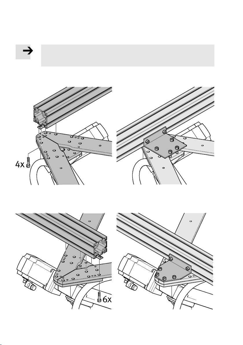
Slot nut mounting across the mounting frame with additional angle brackets
Note
The additional angle brackets are required in the following examples in order to
increase the torsional rigidity and the bearing surface.
Example 1
Holes for slot nut mounting Holes for additional angle brackets
Example 2
Holes for slot nut mounting Holes for additional angle brackets
Fig. 3.8
18 Festo – GDCP-EXPT-KM-KOMP-EN – 1204a – English
Page 19
3 Assembly and installation
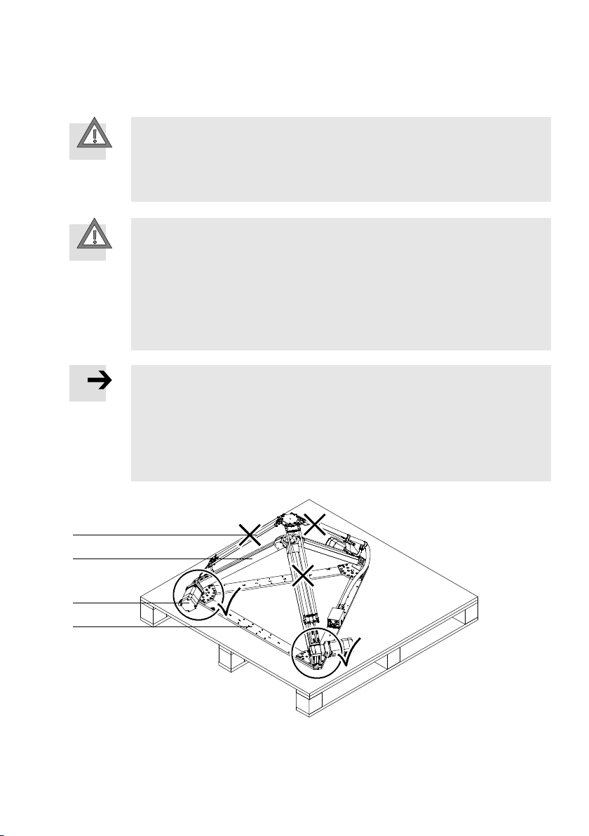
3.8 Preparing tripod kinematics for mounting
Caution
Lifting large loads can lead to permanent injury.
• Depending on size and weight, the tripod kinematics should be lifted and turned
overbytwotothreepersons( Tab. 3.1). An additional person is required for
fastening on the mounting frame.
Caution
Crushing of body parts.
In the event of stress on the joints of the tripod kinematics, the rods can break or the
balls can spring out of the ball cups. This can cause the tripod kinematics to fall down or
tip over. The front unit must not strike against anything or be placed against the floor.
• Grip the EXPT only in the area of the motors and axes or on the mounting frame.
• Set down the tripod kinematics only on the mounting frame.
• Lift up the tripod kinematics in such a way that you can turn them freely.
Note
After being turned over, the tripod kinematics cannot be set down without damaging
them. First, therefore, make the following preparations:
• Prepare the required mounting accessories for mounting on the frame.
• Observe the instructions for the frame used and the intended method of mounting.
• When installing on the frame, be mindful of the position of the pneumatic port 5
( Fig. 3.14).
1
2
3
4
1 Pair of rods
2 Toothed belt axis
Fig. 3.9
Festo – GDCP-EXPT-KM-KOMP-EN – 1204a – English 19
3 Motor
4 Mounting frame
Page 20
3 Assembly and installation
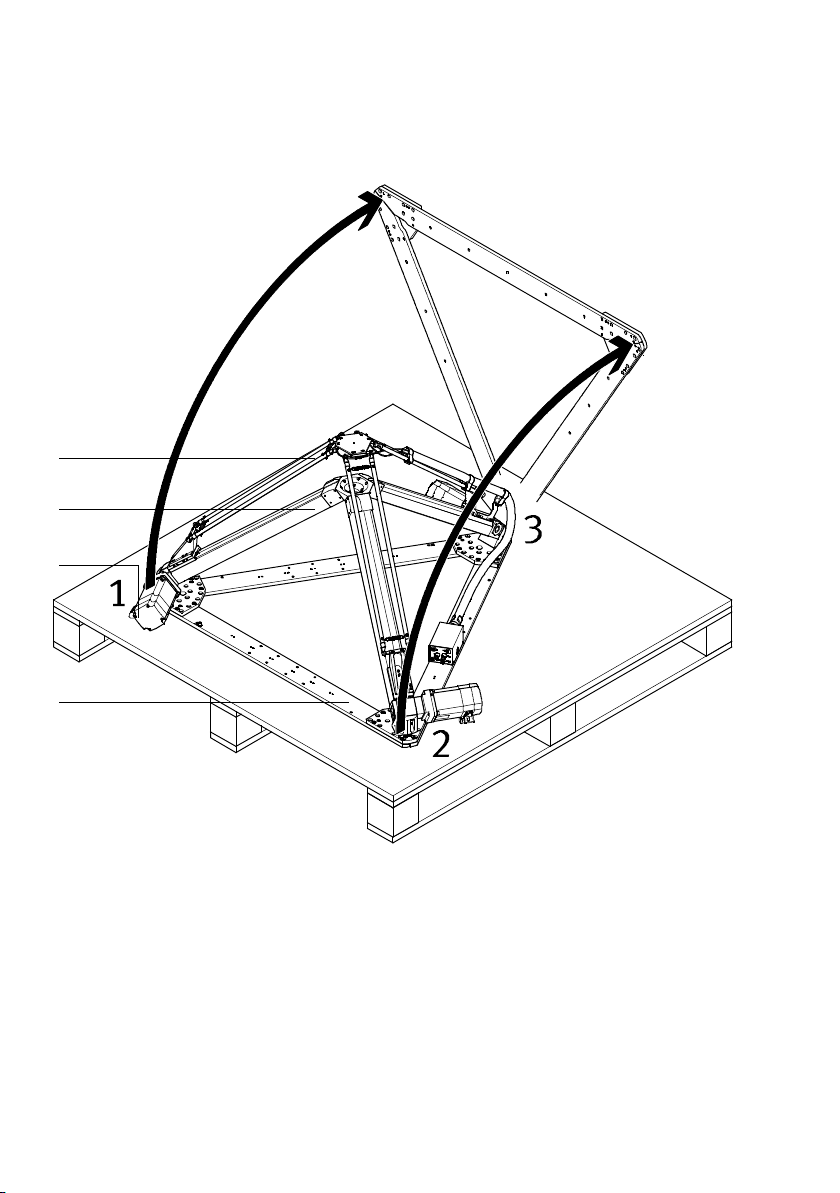
Raising the tripod kinematics to the upright position
1
2
3
4
1 Pair of rods
2 Toothed belt axis
3 Motor
4 Mounting frame
Fig. 3.10
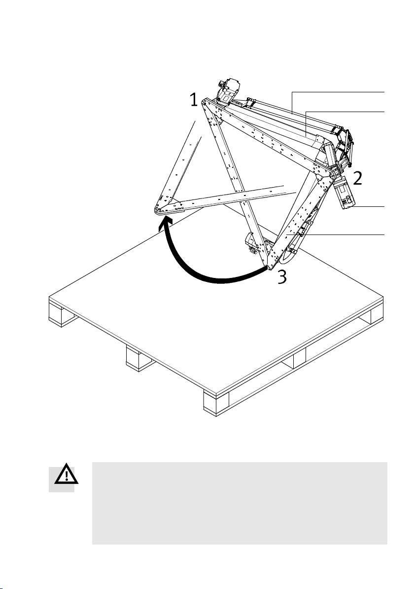
1. Remove the screws using the appropriate tool.
The tripod kinematics are fastened to the base pallet with 6 triple square socket screws.
2. Grip the tripod kinematics together with a second person and only in the area of the motors, axes
and mounting frame (corners 1 + 2).
3. Acting together, raise the tripod kinematics until upright:
• Make sure that the corner 3 on which the tripod kinematics are standing is securely in place and
cannot slip off the pallet.
• Acting together, push the tripod kinematics up until it is resting on corner 3.
20 Festo – GDCP-EXPT-KM-KOMP-EN – 1204a – English
Page 21
3 Assembly and installation
Turning and installing the tripod kinematics
1
2
3
4
1 Pair of rods
2 Toothed belt axis
3 Motor
4 Mounting frame
Fig. 3.11
War ning
Crushing of body parts. If improperly fastened, th e tripod kinematics can come undone
and fall down.
• Fasten the tripod kinematics on the frame in accordance with the specifications on
the assembly drawing.
• Observe the specifications for mounting ( Chapter 3.6 and 3.7).
• Secure the screw connections.
Festo – GDCP-EXPT-KM-KOMP-EN – 1204a – English 21
Page 22
3 Assembly and installation
y
4. Hold the tripod kinematics firmly in the upright position by gripping only on motors, axes or the
mounting frame. Position a third person at c orner 3 of the mounting frame where that person can
grip the product in the area of the motor, axis and mounting frame.
5. The third person turns the tripod kinematics by pulling corner 3 upwards in the area of the motor,
axis and mounting frame.
6. Have three people raise the tripod kinematics into the mounting position on the frame where they
can be screwed in place by a fourth person.
7. The tightening torque is 10 Nm ± 20 % in the case of slot nut mounting.
Note
When installing on the frame, be mindful of the position of the pneumatic and electrical
ports on the interface ho using. The position of the interface housing depends on the
attachment position of the motor on axis A1.
The interface housing is located on the mounting frame opposite motor 1 in relation to
axis 1.
Whether the motors are installed in position V or H ( Fig. 3.12) depends on the type
ordered. The alignment of the A1 axis determines the position of the X axis for the controller's co-ordinate system.
A1
Coordinate s
stem
HV
X
Z
Y
HV
A2
V
H
A3
Fig. 3.12
22 Festo – GDCP-EXPT-KM-KOMP-EN – 1204a – English
Page 23
3 Assembly and installation
3.9 Mounting of attachments
Note
The calibration of the tripod kinematics is lost if the original alignment of the front unit
andthepairsofrodsisnotmaintained.
1. Mark the front unit so that when re-installing, you can put it into exactly the same
position as be fore removal. By de fault, variants T1 to T4 are provided with the marking A1, which points to axis 1.
2. Dismantle the front unit ( Chapter 6.1.3).
3. When re-assembling, make sure that the front unit's original alignment to the
pairs of rods is not lost (observe the markings).
EXPT-...-T0 EXPT-...-T1 to T4
6
1
2
3
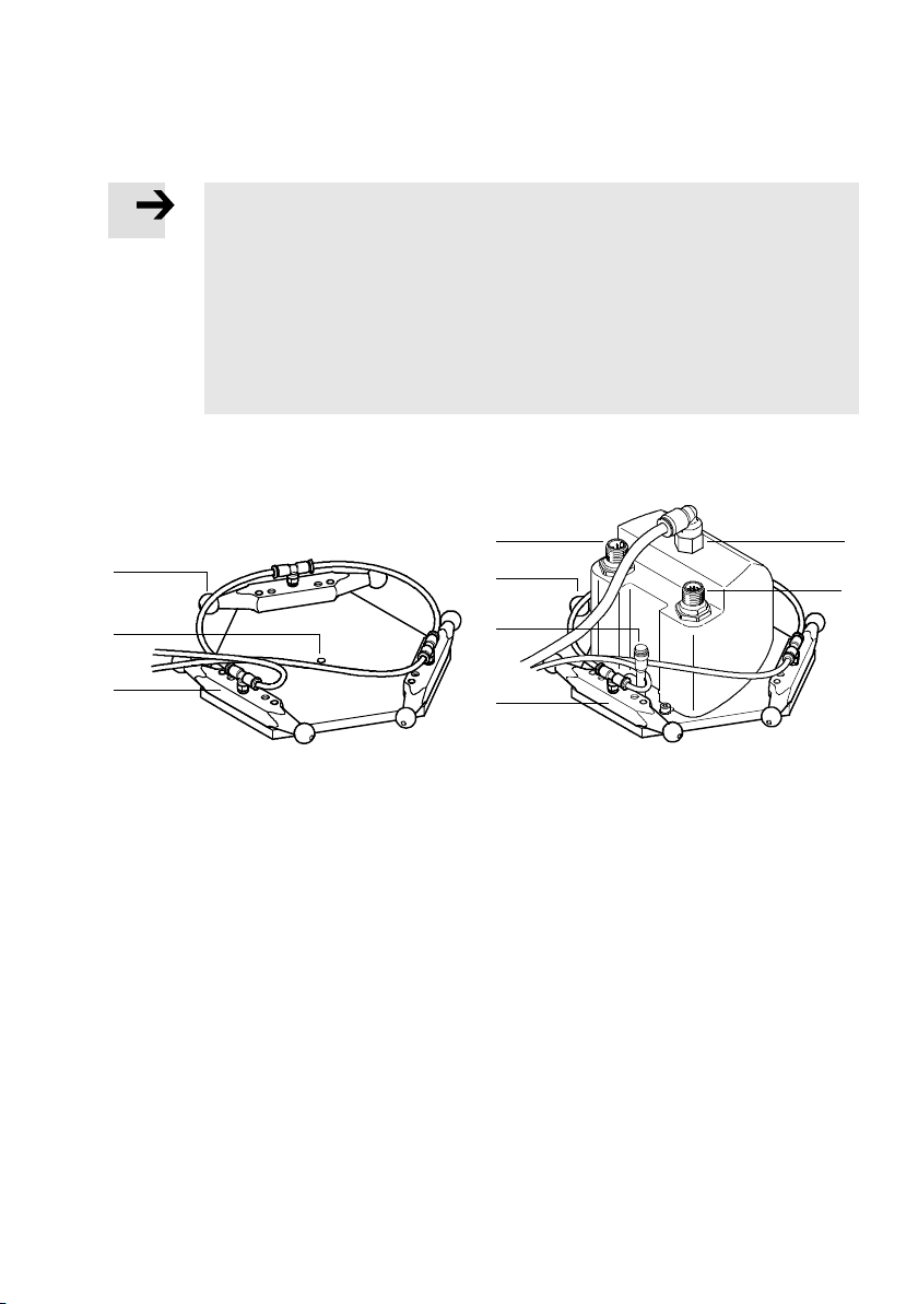
1 Ball
2 Central hole ∅ 4mm
3 Ball stud with pneumatic port
Fig. 3.13
3.9.1 Attachment for EXPT-...-T0
• Mount grippers or other tools on the front unit.
There is no special hole pattern for the standard version of the EXPT-...-T0.. When the product is in
its delivery status, there is only one central ∅ 4 mm hole on this plate, c orresponding to the centre
point (TCP = Tool Cente r Point) . This hole can be used as a starting point for configuring the front
unit with attachments.
3.9.2 Attachment for EXPT-...-T1 to T4
For attaching grippers, suction cups, adapter kits and other accessories to the rotary drive:
( Assembly instructions for the accessories).
1
7
3
4 Airport(variantT2andT4)
5 Connection for encoder cable
6 Connection for motor cable
7 Connection for sensor cable
4
5
Festo – GDCP-EXPT-KM-KOMP-EN – 1204a – English 23
Page 24
3 Assembly and installation
3.10 Installation
3.10.1 Overview
Note
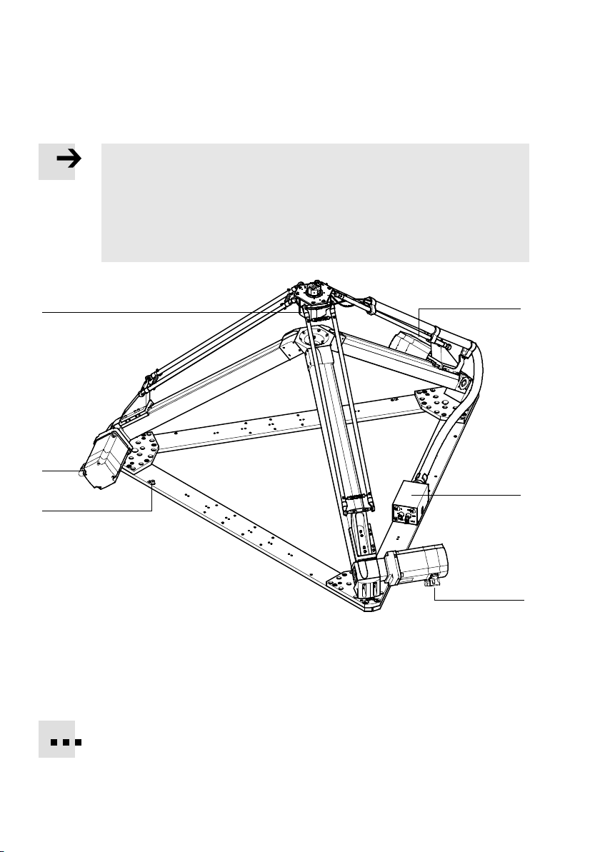
The alignment of the motors will vary according to the configuration of the tripod
kinematics and depends on the order code ( www.festo.com/catalogue).
• Be mindful of the following during assembly and installation:
– the alignment of the motors. The illustrated variant is an example and corres-
ponds t o the standard alignment HHH.
– the interface housing is located opposite motor 1 on the mounting frame.
6
3
4
1 Connections for motor 1
2 Connections for motor 2
3 Connections for motor 3
4 EarthconnectionM6(6x)
Fig. 3.14
1
5
2
5 Interface housing with pneumatic and
electrical ports
6 Rotary drive (variant T1 to T4)
You can expand the installationby ordering additional installation material as accessories
( www.festo.com/catalogue).
24 Festo – GDCP-EXPT-KM-KOMP-EN – 1204a – English
Page 25
3 Assembly and installation
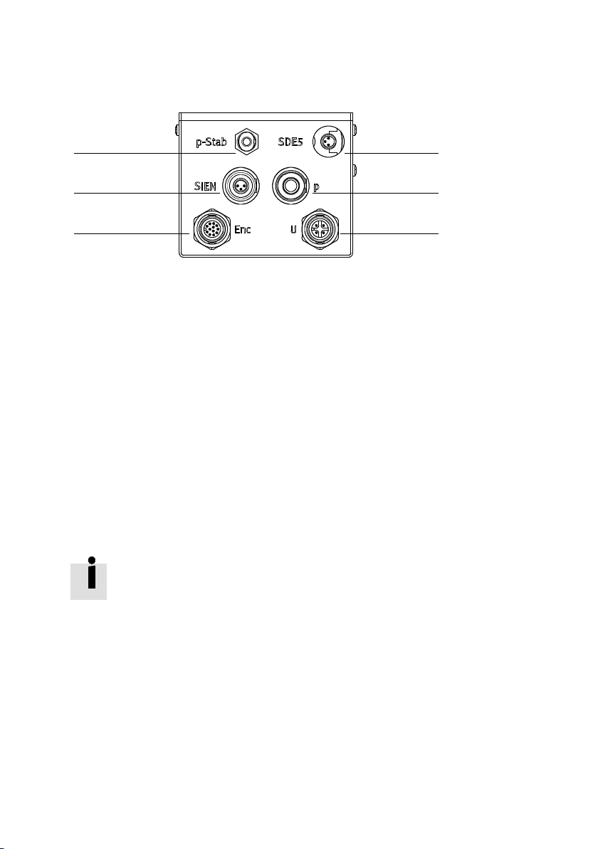
3.10.2 Overview of connections
1
2
3
1 Supply port for rod loss detection
2 Sensor cable connection for position sensing
of rotary drive (variant T1 to T4)
3 Encoder cable connectionfor rotary drive
(variant T1 to T4)
4 Pressure switch SDE5 for rod loss detection
5 Air port for pneumatic rotary through-feed
(variant T2 and T4)
6 Motor cable connection for rotary drive
(variant T1 to T4)
4
5
6
Fig. 3.15
3.10.3 Connect compressed air
• Connect the supply port 1 for rod loss detection on the interface housing to the compressed air
supply.
Rod loss detection is preset at the factory. The built-in pressure switch SDE5 4 sets an output
signal when at least one pair of rods is detached
• Connect the air port 5 or pneumatic rotary through-feed to the front unit (variant T2 and T4 only)
on the interface housing with the air supply.
3.10.4 Installing motor cables and sensor cable
• For the installation, use the optionally supplied cables with pre -assembled plug
connectors ( www.festo.com/catalogue).
• Install one motor cable and one encoder cable on each motor 1 to 3 ( assembly instructions).
• On the interface housing, install the sensor cable for the pressure switch SDE5 4.
Only for variant T1 to T4 with rotary drive:
• On the interface housing, install the motor c able 6 and encoder cable 3 or the rotary drive.
• On the interface housing, install the sensor cable for the position sensing option SIEN of the rotary
drive 2.
Festo – GDCP-EXPT-KM-KOMP-EN – 1204a – English 25
Page 26
3 Assembly and installation
• Later installation and c onnection to the co ntrol components can be carried out only by
a specialist trained as an electrotechnician.
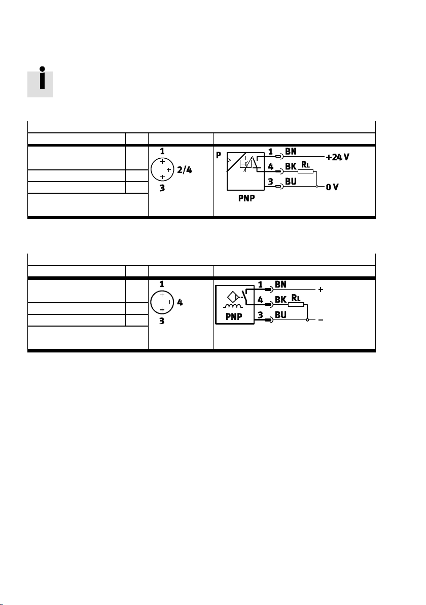
SDE5connection
Port identification/signal Pin Plug pattern Circuit diagram
+24 V DC
1
Operating voltage
Switching output A (out A) 2/4
0V 3
Fig. 3.16
SIEN connection
Port identification/signal Pin Plug pattern Circuit diagram
+10 ... +30 V DC
1
Operating voltage
Switching output A (out A) 4
0V 3
Fig. 3.17
26 Festo – GDCP-EXPT-KM-KOMP-EN – 1204a – English
Page 27
3 Assembly and installation
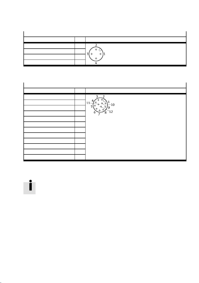
Connection U power supply for rotary drive
Port identification/signal Pin Plug pattern
Operating voltage U 1
Operating voltage V 2
Operating voltage W 3
Protective earth conductor PE 4
Fig. 3.18
Connection of ENC encoder for rotary drive
Port identification/signal Pin Plug pattern
Signal trace A 1
Signal trace A\ 2
Signal trace B 3
Signal trace B\ 4
Signal trace Z 5
Signal trace Z\ 6
Signal trace U 7
Signal trace V 8
Signal trace W 9
GND encoder 10
5 V supply 11
Shield 12
Fig. 3.19
3.10.5 Earthing
• For correct earthing, use one of the earth terminals 4 on the mounting frame
( Fig. 3.14).
Festo – GDCP-EXPT-KM-KOMP-EN – 1204a – English 27
Page 28

4 Commissioning
4 Commissioning
Note
Commissioning must always be carried out by a specially trained technician (a robotics
specialist). The following knowledge is required:
– specialist with knowledge of robotics and CoDeSys
– knowledge of the handling of the Festo components CMMP and CMXR
– knowledge of the handling and operation of the tripod kinematics EXPT.
Commissioning is described in separate documents.
For support in commissioning:
• Please contact your Festo contact person or on the internet ( www.festo.com).
28 Festo – GDCP-EXPT-KM-KOMP-EN – 1204a – English
Page 29
5 Operation and diagnostics
5 Operation and diagnostics
Caution
Crushing of body parts and damage to the system.
Unintended starting can trigger unexpected movements.
• Before any conversion or maintenance work or inspections of the system, ensure
that the system is safely brought to a standstill and is locked off to prevent restarting.
Detached parts could cause unexpected movements or fall down.
• Secure the parts so that they cannot move unexpectedly or bring them into a secure
end position.
Note
Maintenance work should only be conducted by properly trained personnel in accordance with these instructions.
5.1 Maintenance and care
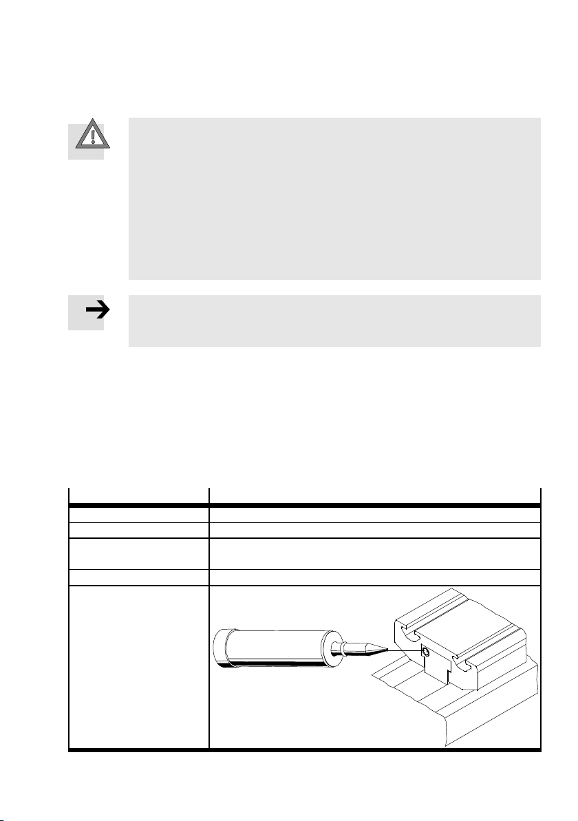
Lubricating ball joints
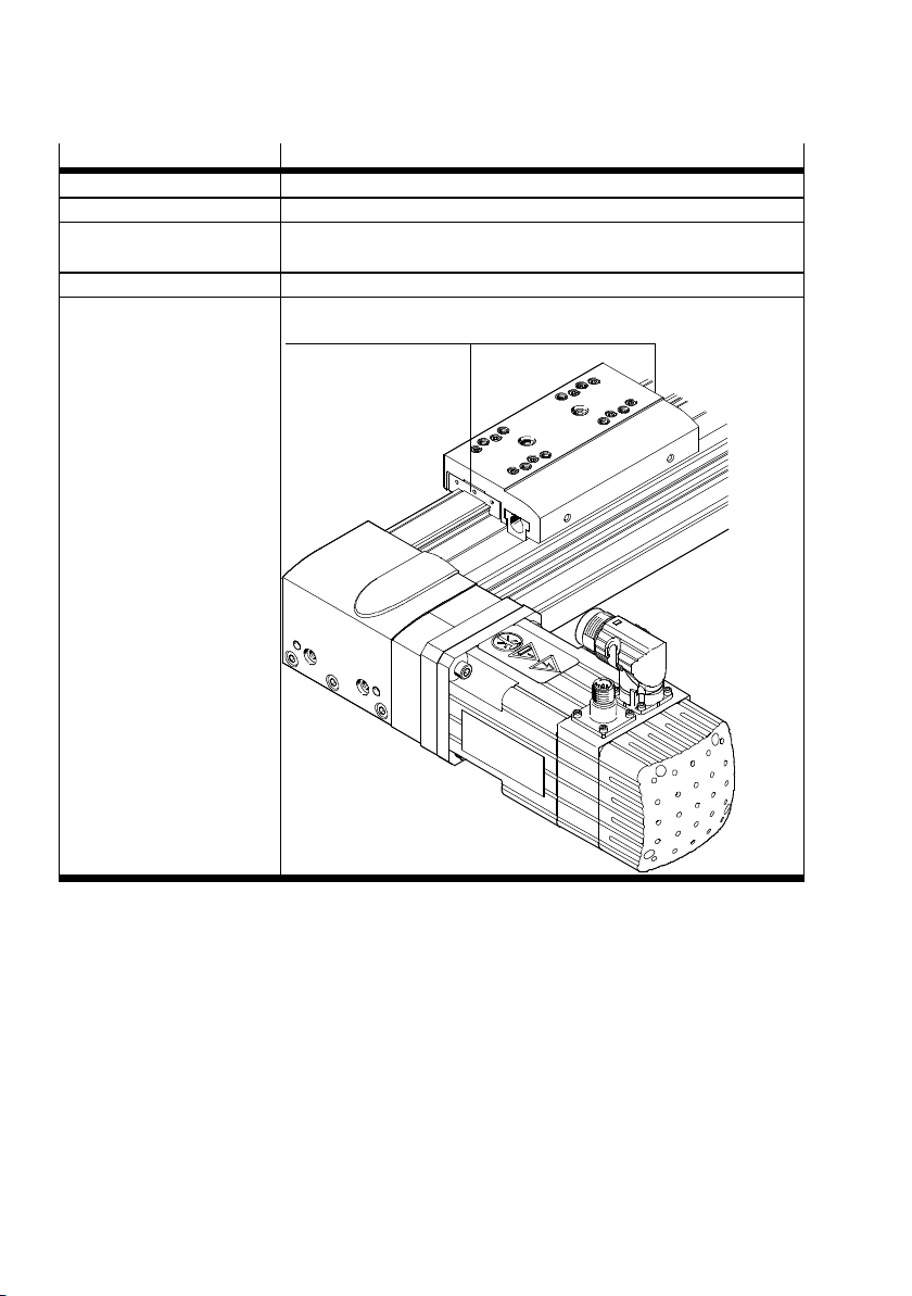
• Lubricate the ball joints ( 2 Fig. 6.4) every 2000 operating hours with lubricant LUB-KC1 (tube
included). Removal is described in ( Chapter 6.1.5).
Lubricating toothed belt axes
• Lubricate the toothed belt axes as follows:
Size
Toothed belt axis DGE-25-...-ZR-RF
Maintenance task Oiling the roller guide
Lubrication interval
in operating hours
Lubricant (oil) Constant OY 390 (from Klüber)
Lubricating point
Tab. 5 . 1
Festo – GDCP-EXPT-KM-KOMP-EN – 1204a – English 29
45/70
[h] 6000
Page 30
5 Operation and diagnostics
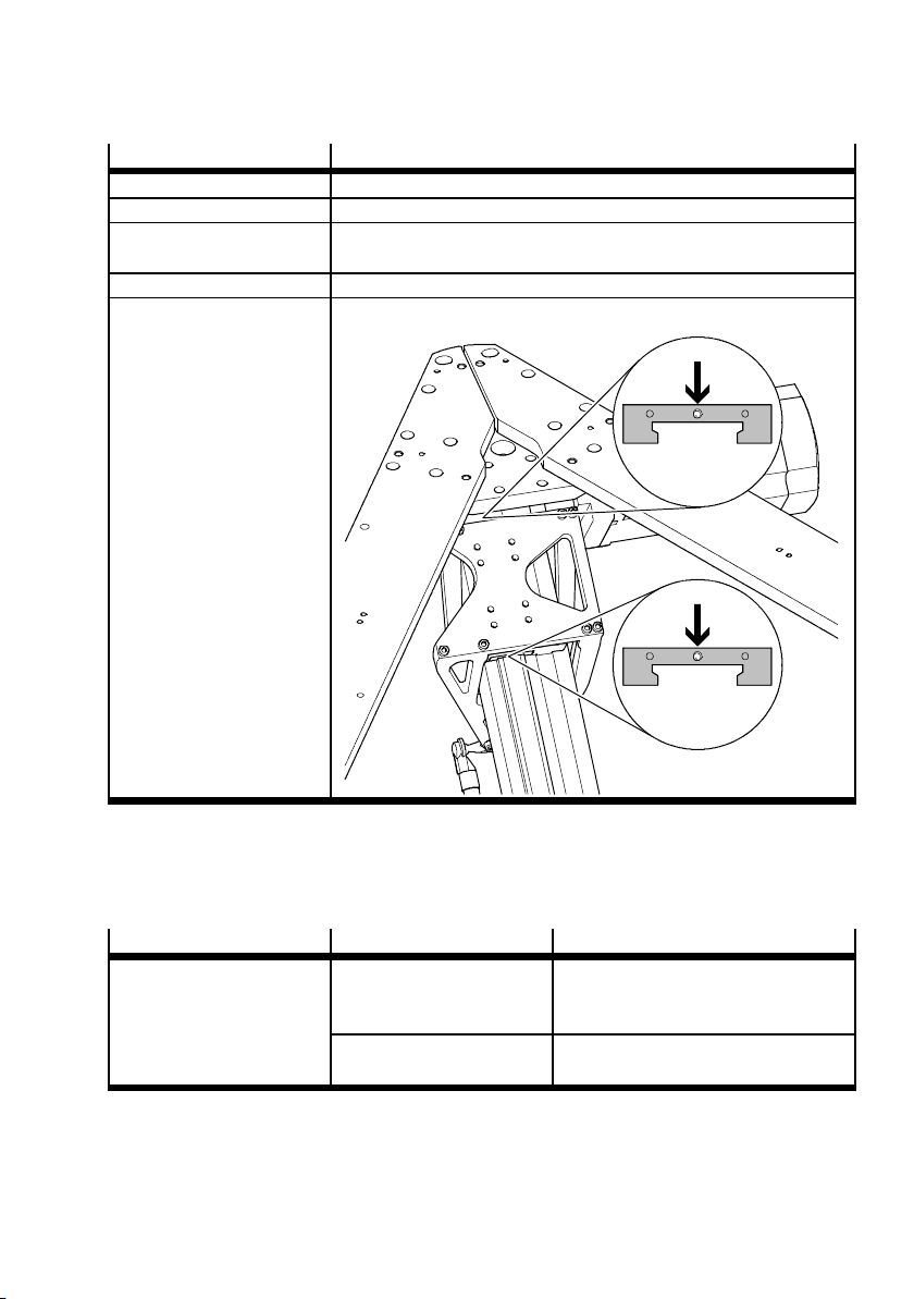
Size 95/120
Toothed belt axis EGC-80-...-TB-KF
Maintenance task Greasing the bearing guide 1
Lubrication interval
[h] 6000
in operating hours
Lubricant (grease) Lub-KC1 ( from Festo)
Lubricating point
1
Tab. 5 . 2
30 Festo – GDCP-EXPT-KM-KOMP-EN – 1204a – English
Page 31
5 Operation and diagnostics
Size 95/120-P8
Toothed belt axis EGC-80-...-TB-KF
Maintenance task Greasing the bearing guide 1
Lubrication interval
in operating hours
Lubricant (grease) Lub-KC1 (from Fe sto)
Lubricating point
[h] 6000
Tab. 5 . 3
5.2 Troubleshooting
Malfunction Possible cause Remedy
Audible leakage of
compressed air
Tab. 5 . 4
Festo – GDCP-EXPT-KM-KOMP-EN – 1204a – English 31
Rod loss Clean, check and grease the ball heads
and cups and re-attach the pair of rods
( Chapter 6.1.5)
Tubing disconnected Re-install the tubing at the intended
place
Page 32
6 Disassembly and repair
6 Disassembly and repair
6.1 Dismantling
Caution
Crushing of body parts and damage to the system.
Unintended starting can trigger unexpected movements.
• Before any conversion or maintenance work or inspections of the system, ensure
that the system is safely brought to a standstill and is locked off to prevent
restarting.
• Remove the following components:
– all cables and tubes from the interface housing
– the motor and encoder cables of the servo motors
6.1.1 Dismounting the tripod kinematics from the frame
Caution
Lifting large loads can lead to permanent injury.
• Due to their size and weight, the tripod kinematics should be held and turned over
by a total of three persons ( Tab. 3.1). An additional person is required to release
the mounting.
Caution
Crushing of body parts.
In the event of stress on the joints of the tripod kinematics, the rods can break or the
balls can spring out of the ball cups. This can cause the tripod kinematics to fall down or
tip over. The front unit must not strike against anything or be placed against the floor.
1. Grip the tripod kinematics only in the area of the motors and axes or on the mounting frame.
2. Hold the tripod kinematics in such a way that you can turn it freely.
3. Set down the tripod kinematics only on the mounting frame.
Note
The tripod kinematics can be set down without damage only after being turned over:
• Prepare the required set-down surface (a pallet).
32 Festo – GDCP-EXPT-KM-KOMP-EN – 1204a – English
Page 33
6 Disassembly and repair
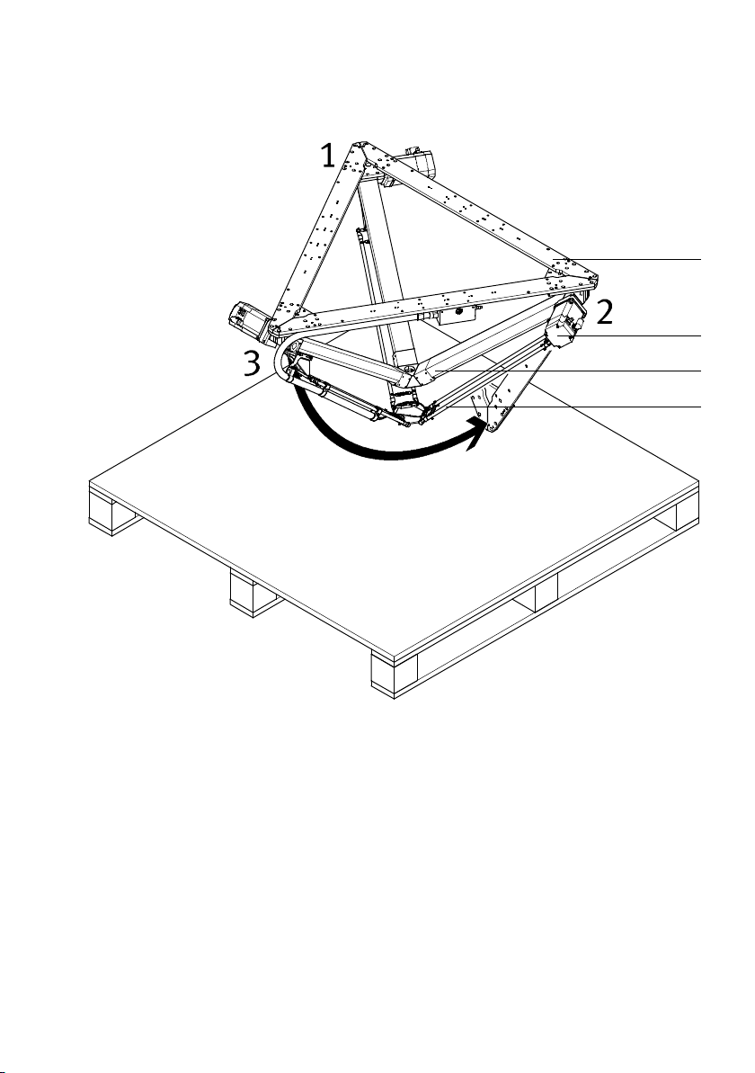
Removing and turning the tripod kinematics
4
3
2
1
1 Pair of rods
2 Toothed belt axis
3 Motor
4 Mounting frame
Fig. 6.1
1. Make absolutely sure that the tripod kinematics are supported at all three c orners before loosening
the mounting screws.
2. Have three people holding the tripod kinematics while a fourth person unscrews them.
3. Carefully remove the tripod kinematics from the mounting frame and bring them to the prepared
pallet.
4. The third person turns the tripod kinematics by gripping c orner 3 at the motor and axis and setting it
down on the set-down surface (e.g. transport pallet).
5. Hold the tripod kinematics firmly in the upright position by gripping on motors, axes or the mounting
frame.
Festo – GDCP-EXPT-KM-KOMP-EN – 1204a – English 33
Page 34
6 Disassembly and repair
Lowering the tripod kinematics
1
2
3
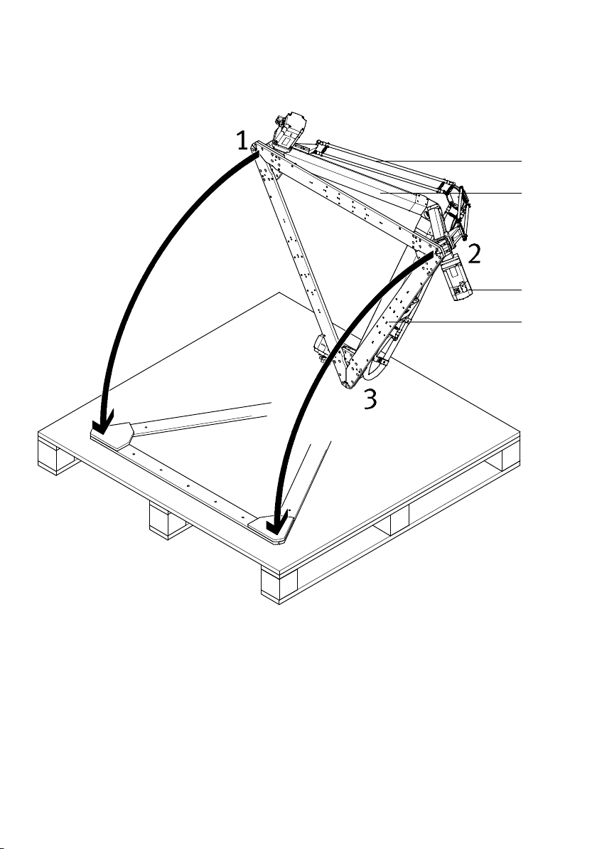
4
1 Pair of rods
2 Toothed belt axis
3 Motor
4 Mounting frame
Fig. 6.2
6. Acting together, lower the tripod kinematics until they are resting on the mounting frame:
• Make sure that the corner 3 on which the tripod kinematics are standing is securely in place and
cannot slip off the pallet.
For transport later:
7. To secure the tripod kinematics for transport, fasten them with the 6 self-tapping screws on the
base plate.
34 Festo – GDCP-EXPT-KM-KOMP-EN – 1204a – English
Page 35
6 Disassembly and repair
6.1.2 Dismounting motors
Caution
Crushing of body parts. When dismounting the motor, the slide of the toothed belt axis
can move freely. This can cause the tripod kinematics to move unexpectedly.
• Secure the tripod kinematics so that they cannot move unexpectedly or bring them
into a secure end position.
Note
Removing a motor causes the referencing of the corresponding axis to be lost. When
commissioning, the axis must be referenced again.
Removal of the motor is required when:
– a concealed mounting hole is used
– the motor needs to be replaced due to a defect
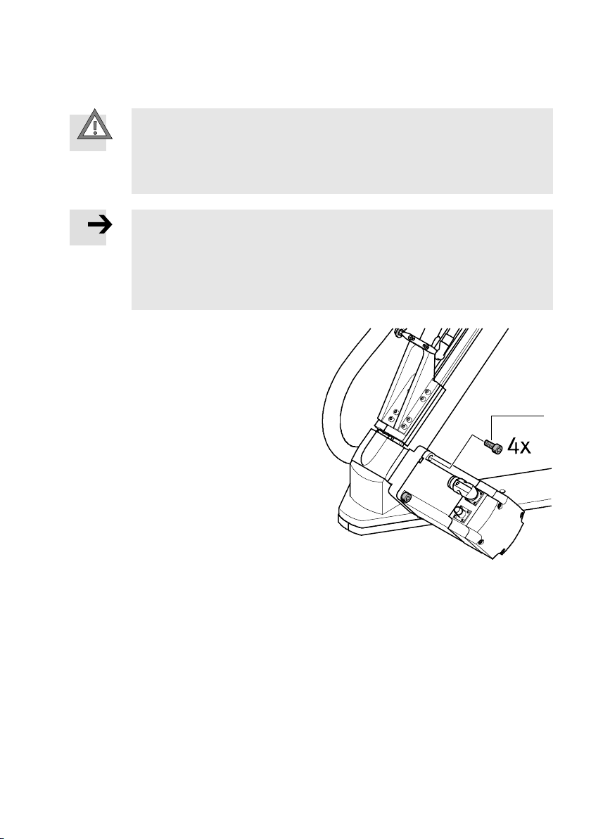
To remove a motor:
• Loosen the screws 1.
If necessary, also remove the coupling
housing.
When re-mounting:
1
• Make sure that the motor has the same
alignment when it is re-assembled
( accompanying assembly instructions for
axial kit).
Fig. 6.3
Festo – GDCP-EXPT-KM-KOMP-EN – 1204a – English 35
Page 36
6 Disassembly and repair
6.1.3 Dismounting the front unit
Grippers, suction cups or other accessories can be mounted on the front unit of the tripod kinematics,
as required by the customer.
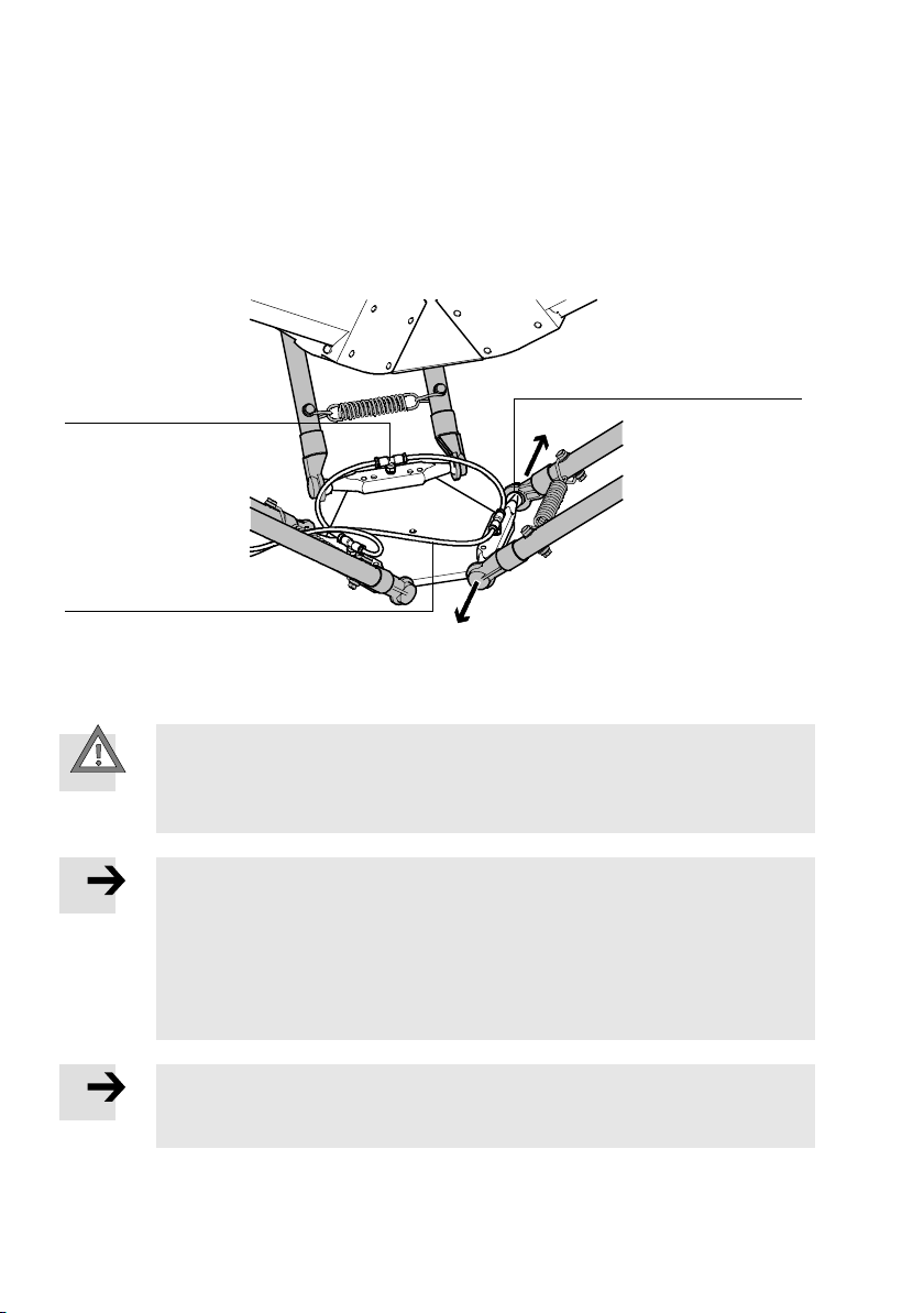
The front unit is fitted with ball studs with balls for attaching the pairs of rods. The balls form ball joints
with the ball cups of the pairs of rods 2. T-fittings are provided on the ball studs 3 to connect the
compressed air for rod loss detection.
2
3
1
1 Hose
3 Push-in T-fitting
2 Ball joint
Fig. 6.4
Caution
Danger of crushing exists when disconnecting the ball cups from the balls.
• Be sure that you do not let your fingers be pinched between the balls and the ball
cups.
Note
The calibration of the tripod kinematics is lost if the original alignment of the front unit
to the pairs of rods is not maintained.
• Mark the front unit for variant T0 so that when re-installing, you can put it into
exactly the same position as before removal.
By default, variants T1 to T4 are provided with the marking A1, which points to
axis 1.
Note
After the first pair of rods is disconnected, the other two pairs can move causing the
front unit to lose its stability and its position.
36 Festo – GDCP-EXPT-KM-KOMP-EN – 1204a – English
Page 37
6 Disassembly and repair
To disconnect the front unit, proceed as follows:
1. Vent the supply port (t o depressurise).
2. Pull the rod loss detection hoses coming from the protective conduit 1 out of their push-in T-fittings 3 ( Fig. 6.4).
Note
For variants T1 to T4, the motor cable 6,encodercable5 and sensor cable 7 must
also be removed.
For variants T2 and T4, the hose from the air supply port 4 must also be removed.
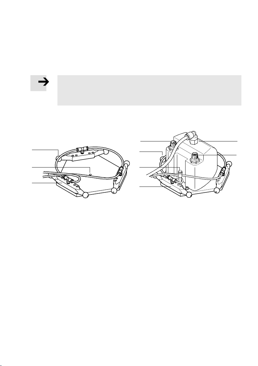
EXPT-...-T0 EXPT-...-T1 to T4
4
5
1
2
3
1 Ball
2 Central hole ∅ 4mm
3 Ball stud with pneumatic port
6
1
7
3
4 Airport(variantT2andT4)
5 Connection for encoder cable
6 Connection for motor cable
7 Connection for sensor cable
Fig. 6.5
3. Disconnect the rods of the first rod pair from the balls as follows:
Hold the front unit firmly in one hand and pull the first rod from the ball with your other hand. The
pretension of the springs means that a relatively high amount of force is needed to separate the
joints 2 ( Fig. 6.4). The spring forces between the rods can cause the partially disconnected pair
of rods to cross over. Keep holding the front unit firmly in one hand and pull the second rod from the
ball.
4. Place the front unit in a position which allows you to disconnect the other two pairs of rods from the
front unit.
5. Disconnect the second and third pair of rods and remove the front unit.
Festo – GDCP-EXPT-KM-KOMP-EN – 1204a – English 37
Page 38
6 Disassembly and repair
6.1.4 Dismantling the protective conduit
EXPT-...-T0 to T4 EXPT-...-T1 to T4
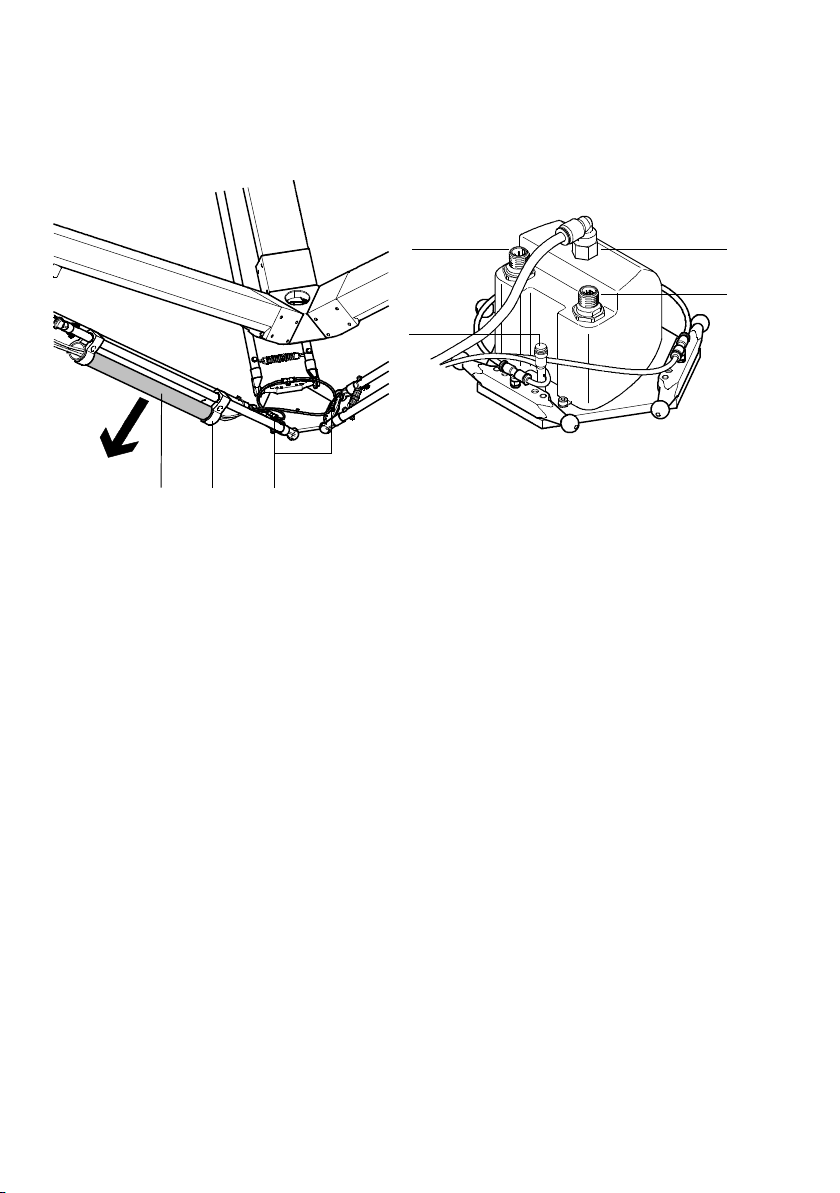
6
7
12
1 Protective conduit
2 Retainer
3 T-fitting
3
4 Airport(variantT2andT4)
5 Connection for encoder cable
6 Connectionfor motor cable
7 Connectionfor sensor cable
Fig. 6.6
To remove the protective conduit, proceed as follows.
1. Vent the supply ports.
2. Pull the rod loss detection hoses coming from the protective conduit 1 out of their push-in T-fittings 3.
For T1 to T4: remove the encoder cable 5, motor cable 6 and sensor cable 7.
For T2 and T4: remove the air hose 4.
3. Undo the screws on the retainers 2
(Tightening torque for re-assembly: 0.25Nm ±20%).
4. Pull the protective conduit 1 from the retainers.
For installation of a new tubing holder ( assembly instructions). Acc essories and spare parts can be
found at: ( www.festo.com).
4
5
38 Festo – GDCP-EXPT-KM-KOMP-EN – 1204a – English
Page 39
6 Disassembly and repair
6.1.5 Dismounting a pair of rods
The following preparation work is necessary before dismounting a pair of rods:
– removal of the front unit
– removal of the protective conduit and the tubing holder if necessary ( 6.1.4).
Removing pairs of rods
Note
Swapping pairs of rods around causes loss of calibration and thus a reduction in absolute positioning accuracy.
• Put markings on the pairs of rods so that when re-installing, you can put them into
exactly the same position as before removal.
• If fitted, remove the protective conduit and the tubing holder before removing the
pairsofrods( 6.1.4).
After removing the front unit ( 6.1.3) and the protective conduit and tubing holder if necessary
( 6.1.4):
1. Carefully separate a pair of rods from the upper ball studs and remove the pair of rods.
2. Disconnect and remove the other pairs the same way as the first.
Cleaning, inspecting and greasing the tripod kinematics
1. Use a cloth to clean the balls and ball cups of the detached rods.
2. Check the balls and ball cups for damage.
3. Likewise check th e springs, pins, washers and suppor ts for damage.
If there is any damage:
• Replace the components in question.
Replacements must always be done in pairs ( www.festo.com/spareparts).
4. Thinly coat the friction marks on the balls and ball cups with silicone-free grease, e.g. LUB-KC1
( www.festo.com/spareparts) .
5. After mounting the pairs of rods (see next section), remove the exc ess grease on the balls and/or
ball cups.
Installing the pairs of rods
Note
Swapping pairs of rods around causes loss of calibration and thus a reduction in absolute positioning accuracy.
• Maintainthe original arrangement of the pairs of rods and the front unit.
To install the rods:
Start by attac hing the pairs of rods on the side of the connection block 9 ( Fig. 2.1).
1. Place the ball cup of the first rod on the ball on the ball stud.
2. Pull apart the springs with the second rod.
3. Place the ball cup of the second rod on the other ball.
4. Repeat the procedure until all pairs of rods are attached to the connection block.
5. Attach the pairs of rods to the front unit.
Festo – GDCP-EXPT-KM-KOMP-EN – 1204a – English 39
Page 40

6 Disassembly and repair
6.2 Repair
• Observe the information regarding mounting and dismantling ( Chapter 6.1).
Recommendation:
• Consult our repair service.
This ensures that the necessary fine adjustments and checks will be given particular attention.
• Information about spare parts and auxiliary means can be found at: ( www.festo.com/spareparts).
6.3 Accessories
• Please select the appropriate accessories from our catalogue
( www.festo.com/catalogue).
6.4 Disposal
• When dismantling parts, observe the instructions ( Chapter 6.1).
• Observe the local regulations for environmentally-friendly disposal of modules.
Some materials are listed in the technical data section to enable separate disposal of
particular materials ( Chapter A.1, Tab. A.2).
• Handle the lubricants (greases, oils) in accordance with the applicable regulations
governing health and safety and hazardous materials.
• Observe the local regulations regarding waste disposal and the environment.
40 Festo – GDCP-EXPT-KM-KOMP-EN – 1204a – English
Page 41
A Technical appendix
A Technical appendix
A.1 T echnical data for tripod kinematics EXPT-...-T0 to T4
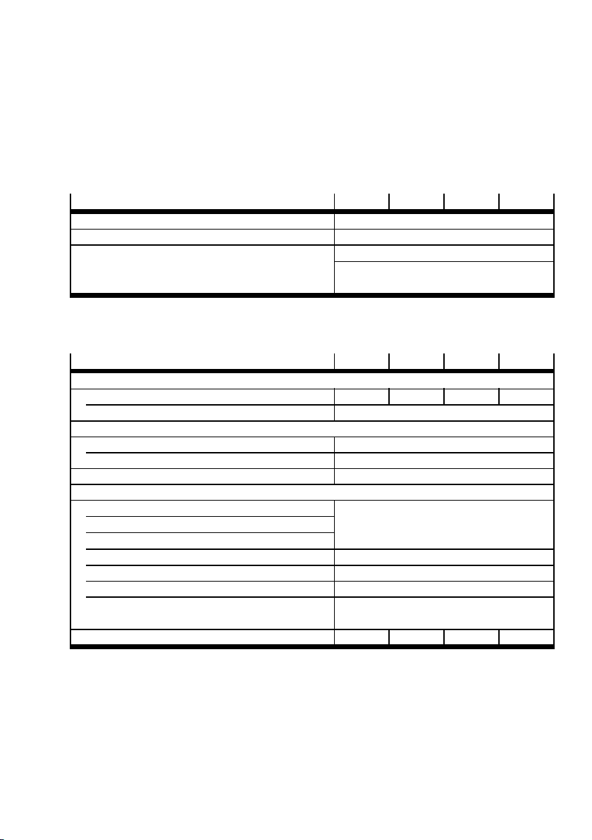
A.1.1 General
Size
Design Tri po d k in em atics
Mounting position Horizontal
Type of mounting Direct mounting
Tab. A . 1
A.1.2 Mechanical
Size
Working space
Nominal diameter [mm] 450 700 950 1200
Nominal he ight [mm] 100
Rod loss detection
Pneumatic connection Hose with a nominal diameter of 4mm
Operating pressure [bar] 2…8
Note on materials Contains PWIS
Materials
Front Unit Aluminium
Ball stud
Coupling housing
Pair of rods Plastic, carbon-fibre reinforced
Balls Ceramic
Ball cups Polyamide
Screws, pins, washers
nuts, springs, sleeves
Base weight of the kinematics [kg] 45 47.5 61.5 66
1) PWIS = paint-wetting impairment substances
Tab. A . 2
45 70 95 120
Profile mounting
(with additional angle brackets if necessary)
45 70 95 120
1)
Steel
Festo – GDCP-EXPT-KM-KOMP-EN – 1204a – English 41
Page 42
A Technical appendix
A.1.3 Dynamic
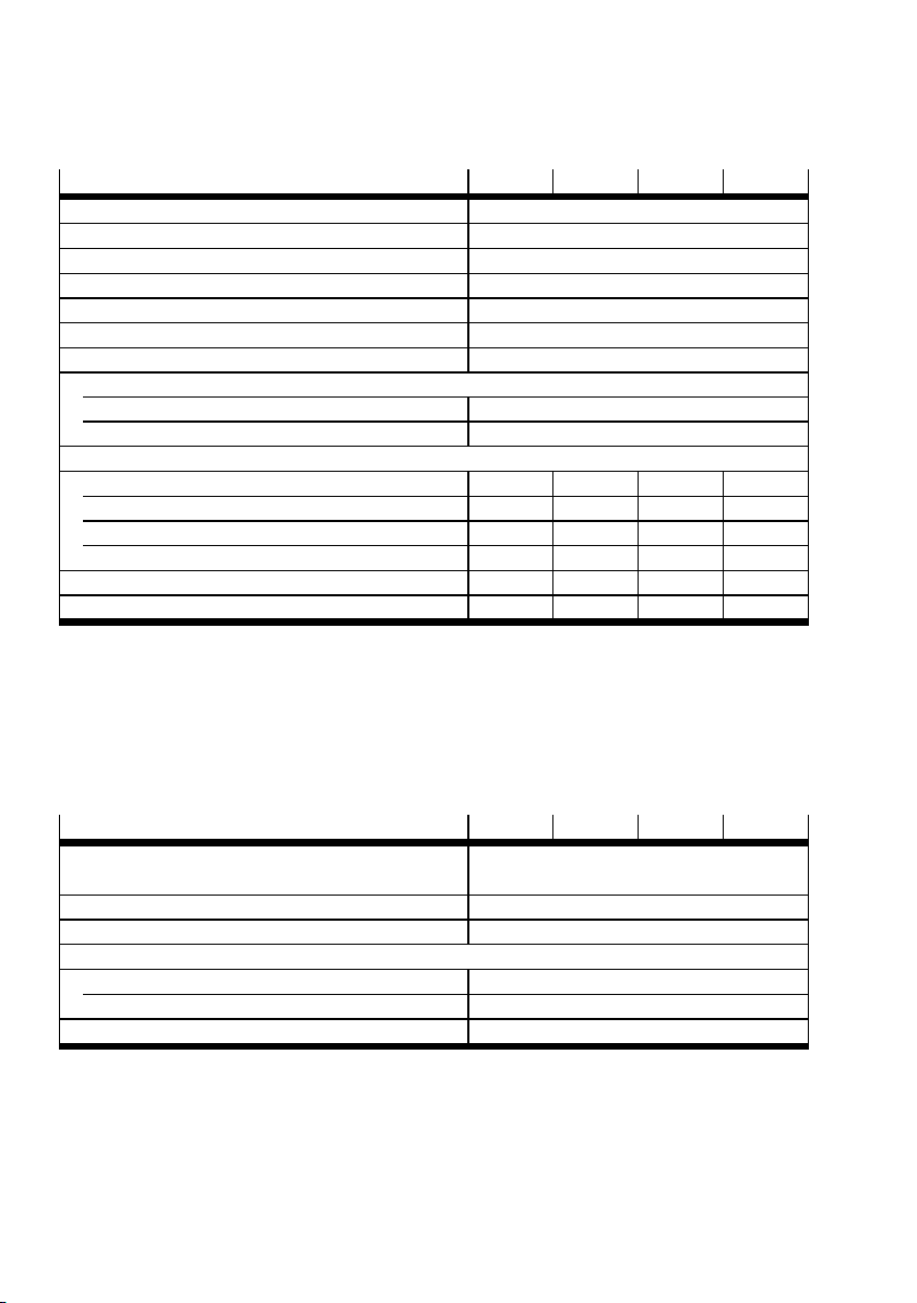
Size
45 70 95 120
Motor type Servo motor
Max. acceleration
Max. speed
Max. picking rate
1)
1)
1)5)
[m/s2] 110
[m/s] 7
[picks/min] 150(in12inchcycle)
Repetition accuracy [mm] ±0.1
Positioning accuracy
Tra ck preci si on
Effective load
2)
3)
4)
[mm] ±0.5
[mm] ±0.5
With min. dynamic response [kg] 5
With max. dynamic response [kg] 1
Max. process force in Z direction
With working space ∅ [mm] 0 0 0 0
Process force in Z direction [N] 1300 1000 1000 850
With working space ∅ [mm] 112.5 175 237.5 300
Process force in Z direction [N] 1000 750 750 750
Max. frame strength horizontal [N] ±145 ± 150 ± 200 ± 215
Max. frame strength vertical [N] ± 250 ± 290 ± 325 ±475
1) When used in conjunction with motor controller C MMP-AS-C5-3A and controller CMXR (multi- axis control).
2) Only with calibrated system (order code S)
3) Only with calibrated system (order code S) and a speed of ≤ 0. 3 m/s
4) Sum of load mass and accessories attached to the front unit
5) With a max. transie nt response of ±0.5mm
Tab. A . 3
A.1.4 Operating and environmental conditions
Size
45 70 95 120
Operating medium Compressed air in accordance with
ISO 8573-1:2010 [5:4:1]
Ambient temperature [°C] 0…+40
Storage temperature [°C] –10 … +60
Air humidity
– [%] 5 … 95, non-condensing
T1 to T4 [%] 20 … 80, non-condensing
Duty cycle [%] 100
Tab. A . 4
42 Festo – GDCP-EXPT-KM-KOMP-EN – 1204a – English
Page 43
A Technical appendix
A.2 Technical data of front unit for EXPT-...-T1 to T4
A.2.1 General
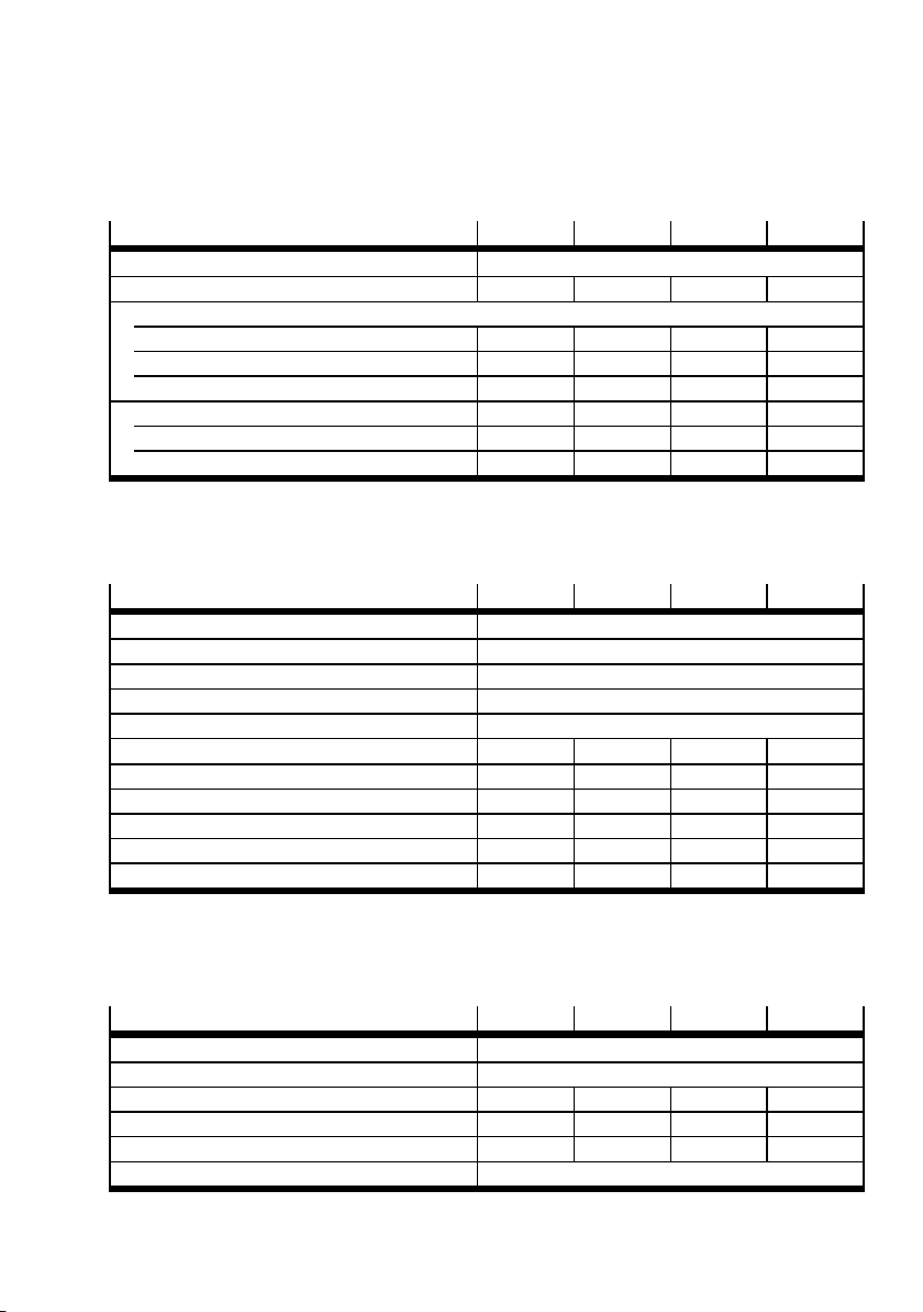
Var ian t
Design Electro-mechanical rotary module
Size 8 8 11 11
Compressed air
Operating pressure [bar] – –0.9 … +10 – –0.9 … +10
Standard nominal flow rate [l/min] – 350 – 350
Permissible leakage
1)
[l/h] – 10 – 10
Air through-feed – Yes – Yes
Pneumatic connection – G1/8 – G1/8
Nominal size [mm] – 4 – 4
1) At 6 bar nominal pressure after 10 million cycles
Tab. A . 5
A.2.2 Mechanical
Var ian t
Rotation angle Infinite
Gear ratio [mm] 30:1
Repetition accuracy [°] ±0.01
Max. output speed [rpm] 200
Max. continuous speed [rpm] 117
Nominal torque [Nm] 0.75 0.75 1.8 1.8
Peak torque [Nm] 1.8 1.8 4.5 4.5
Max. axial force [N] 200 200 300 300
Max. pull-out torque, static [Nm] 15 15 40 40
Perm. mass moment of inertia of load [kgm2] 0.0026 0.0026 0.006 0.006
Load for E XPT
1)
[g] 640 690 850 900
T1 T2 T3 T4
T1 T2 T3 T4
1) The load must be taken into account when calculating the effective load of the EXPT
Tab. A . 6
A.2.3 Electrical
Var ian t
T1 T2 T3 T4
Nominal voltage AC [V] 230
Max. output speed [rpm] 200
Nominal motor current [A] 0.31 0.31 0.74 0.74
Peak motor current [A] 0.61 0.61 1.5 1.5
Rated motor output [w] 9.2 9.2 22.1 22.1
Duty cycle [%] 100
Tab. A . 7
Festo – GDCP-EXPT-KM-KOMP-EN – 1204a – English 43
Page 44

Copyright:
Festo AG & Co. KG
Postfach
D-73726 Esslingen
Phone:
+49 711 347 0
Fax:
+49 711 347 2144
e-mail:
[email protected]
Reproduction, distribution or sale of this document or communication of its contents to others without express authorization is
prohibited. Offenders will be liable for damages. All rights reserved in the event that a patent, utility model or design patent is
registered.
Internet:
www.festo.com
Original: de
Version: 1204a
 Loading...