

Page 1
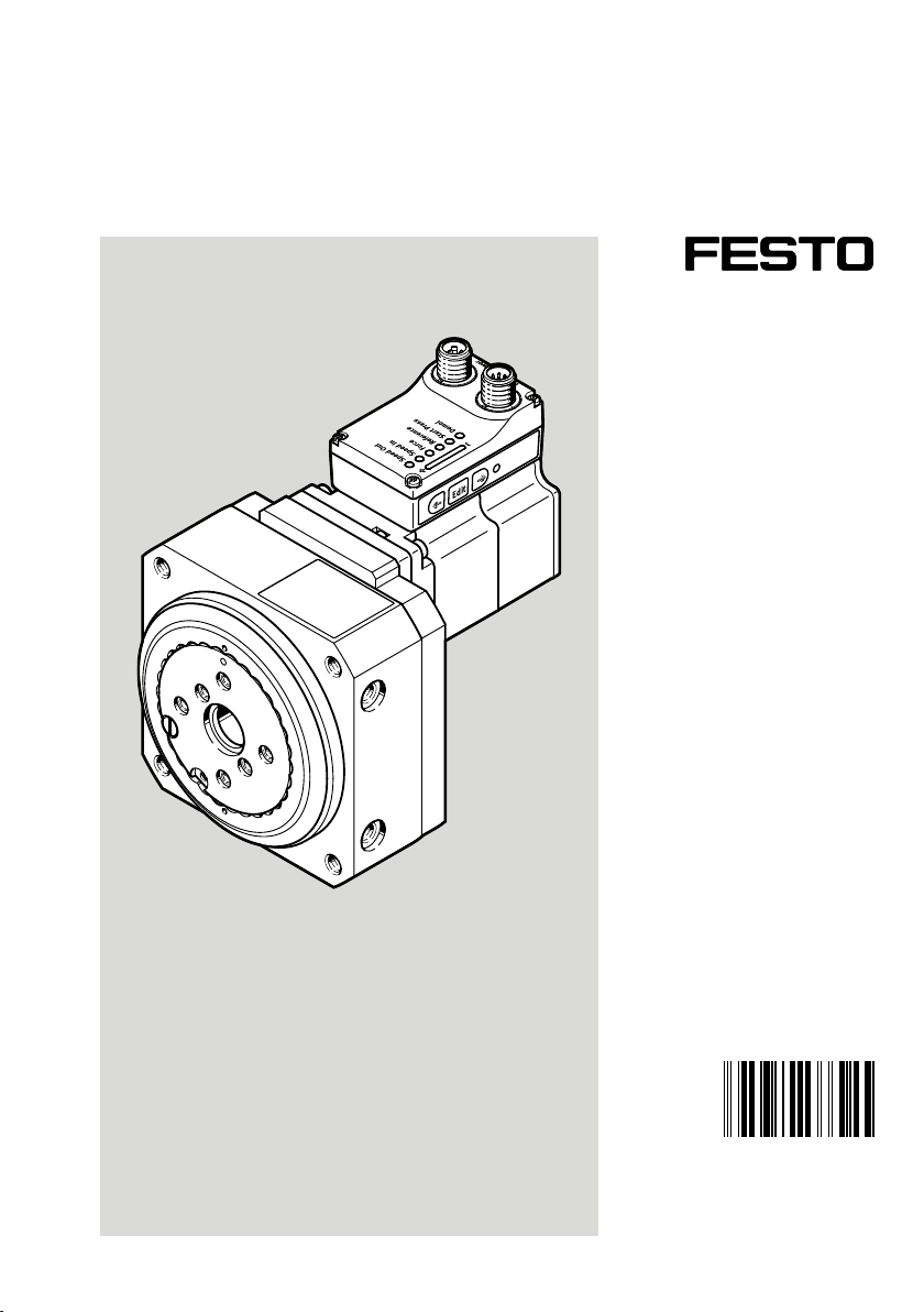
ERMS
Rotary drive unit
Instructions| Operating
8103921
8103921
2019-07
[8103923]
Page 2

Translation of the original instructions
IO-Link® is a registered trademark of its respective trademark holder in certain countries.
2 Festo — ERMS — 2019-07
Page 3

Table of contents
1 About this document................................................................................................... 4
1.1 Applicable documents.................................................................................................. 4
2 Safety........................................................................................................................... 4
2.1 Safety instructions........................................................................................................ 4
2.2 Intended use................................................................................................................ 4
2.3 Training of qualified personnel..................................................................................... 4
3 Additional information................................................................................................ 4
4 Service..........................................................................................................................4
5 Product overview......................................................................................................... 5
5.1 Scope of delivery.......................................................................................................... 5
5.2 Function....................................................................................................................... 5
5.3 System overview.......................................................................................................... 5
5.3.1 Product design........................................................................................................6
6 Transport..................................................................................................................... 6
7 Assembly..................................................................................................................... 7
7.1 Mounting drive............................................................................................................. 7
7.2 Mounting attachment component................................................................................ 9
8 Installation.................................................................................................................. 9
9 Commissioning............................................................................................................ 11
9.1 Commissioning "DIO operation (digital I/O)"............................................................... 12
9.2 Commissioning "IO-Link Operation"............................................................................ 13
10 Operation..................................................................................................................... 13
10.1 Master control.............................................................................................................. 13
10.2 Dimension reference system........................................................................................ 14
10.3 Display and operating components (HMI)..................................................................... 15
10.4 Homing..........................................................................................................................16
10.5 End-to-end operation................................................................................................... 17
11 Maintenance................................................................................................................ 18
11.1 Disassembly................................................................................................................. 18
11.2 Cleaning....................................................................................................................... 18
12 Malfunctions............................................................................................................... 19
12.1 Fault clearance............................................................................................................. 21
12.2 Repair............................................................................................................................21
13 Disposal........................................................................................................................21
14 Technical data............................................................................................................. 22
3Festo — ERMS — 2019-07
Page 4
About this document
1 About this document
1.1 Applicable documents
All available documents for the product èwww.festo.com/pk.
Type Product Contents
EMCS-ST Integrated drive Description, commissioning
NEFC-M12G8-0.3-M12G5-LK Adapter Instruction manual, mounting
Tab. 1 Other applicable documents for the product
2 Safety
2.1 Safety instructions
– Observe labelling on the product.
– Prior to assembly, installation and maintenance work: Switch off power supply, ensure that it is
off and secure it against being switched back on.
– Store the product in a cool, dry, UV-protected and corrosion-protected environment. Ensure that
storage times are kept to a minimum.
– Observe tightening torques. Unless otherwise specified, the tolerance is±20%.
2.2 Intended use
The rotary drive unit ERMS is used as intended for the rotary movement of payloads.
2.3 Training of qualified personnel
Installation, commissioning, maintenance and disassembly should only be conducted by qualified personnel.
The personnel must be familiar with the installation of mechatronic control systems.
3 Additional information
– Accessories èwww.festo.com/catalogue
– All available documents for the product èwww.festo.com/sp.
4 Service
Contact your regional Festo contact person if you have technical questions èwww.festo.com.
Festo — ERMS — 2019-074
Page 5
Product overview
5 Product overview
5.1 Scope of delivery
The following components are included in the scope of delivery:
– Rotary drive unit ERMS
– Instruction manual for the rotary drive unit ERMS
– Adapter for IO-Link operation (optional accessory) èwww.festo.com/catalogue
5.2 Function
The rotation of the motor is transferred to the rotary table by a helical gear unit.
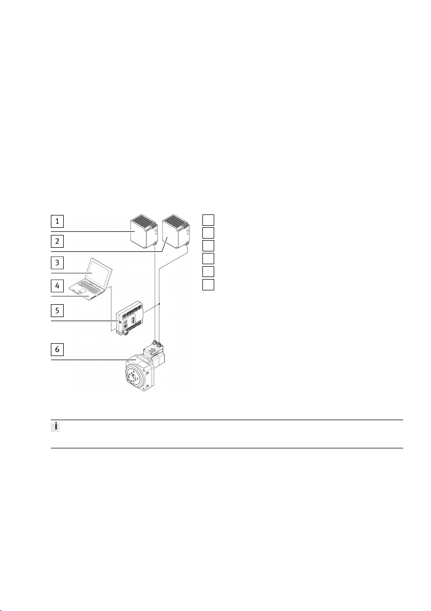
5.3 System overview
1
PELV fixed power supply for power voltage
2
PELV fixed power supply for logic voltage
3
Application software
4
PC or Laptop
5
Controller or IO-Link master
6
Rotary drive unit ERMS
Fig. 1 System overview
The positions 1…5 are not in scope of delivery.
5Festo — ERMS — 2019-07
Page 6
Transport
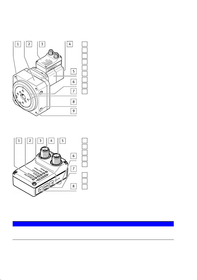
5.3.1 Product design
1
Rotary drive ERMS
2
Product labelling
3
Controller housing
4
Warning symbol "Attention! Hot surface"
5
Integrated drive EMCS-ST
6
Rotating plate
7
Thread/centring holes for attachment components
8
Thread for mounting (lateral)
9
Thread for mounting (front)
Fig. 2 Product design
Electrical connections, display and operating components (HMI)
1
LED display Menu (Speed Out, ..., Demo)
2
LED parameter display
3
LED display C/Q
4
Power voltage connection [power]
5
Logic voltage and digital I/O or IO-Link [Logic] connection
6
Pushbutton actuator (right arrow)
7
Pushbutton actuator (Edit)
8
Pushbutton actuator (left arrow)
Fig. 3 Electrical connections, display and operating components (HMI)
6 Transport
NOTICE!
Unexpected and unbraked movement of components
• Secure moving components for transport.
• Take product weight into account è 14 Technical data.
6 Festo — ERMS — 2019-07
Page 7
Assembly
7 Assembly
WARNING!
Risk of injury due to unexpected movement of components.
The drive can move freely in the voltage-free state. This can cause unexpected movements of the connected mechanics and crush parts of the body.
• Bring moving parts of the mechanical system into a safe position.
Requirements
– Do not modify screws and threaded pins.
Exception: direct request in these operating instructions to make changes.
– Connect motor cables only after the drive is mounted.
Loss of homing settings due to change of position of the stop.
• After completion of mounting, start homing è 9 Commissioning.
7.1 Mounting drive
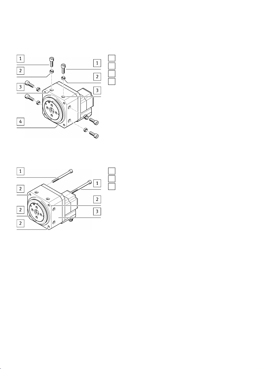
The drive can be mounted on the side or front/rear:
– Side mounting è Fig.4
– Front/rear mounting è Fig.5
Position the drive in such a way that its operating components are accessible.
– Select mounting attachments è Tab. 2.
– Make sure that mounting components are outside the positioning range.
– Mount the drive.
– Tighten screws evenly.
– Observe the maximum screw-in depth and tightening torque è Tab. 2.
Size 25 32
Screw M6 M8
Tightening torque [Nm] 8 24
Centring [mm] Æ9H7 Æ12H7
Max. screw-in depth (side mounting) [mm] 9.5 15
Tab. 2
7Festo — ERMS — 2019-07
Page 8
Assembly
Side mounting of drive
Fig. 4 Side mounting of drive
Front/rear mounting of drive
1
Screw
2
Centring sleeve
3
Mounting hole
4
Rotary drive unit ERMS
1
Screw
2
Mounting hole
3
Rotary drive unit ERMS
Fig. 5 Front/rear mounting of drive
8 Festo — ERMS — 2019-07
Page 9
Installation
7.2 Mounting attachment component
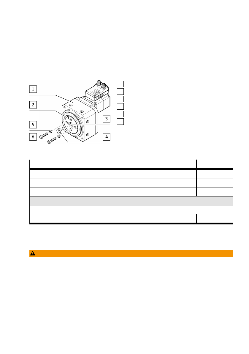
– Select mounting attachments è Tab. 3.
– Mount the attachment component on the rotary table with screws and centring sleeves.
– Tighten screws evenly.
– Observe the maximum screw-in depth and tightening torque è Tab. 3.
1
Rotary drive unit ERMS
2
Mounting hole
3
Central drill hole
4
Central drill hole for centring sleeve
5
Mounting hole for centring sleeve
6
Screw
Fig. 6 Mounting attachment component
Size 25 32
Screw M5 M5
Max. screw-in depth [mm] 8.5 10
Tightening torque [Nm] 5 5
Centring
Mounting hole [mm] Æ7H7
Central drill hole [mm] Æ15H8 Æ20H8
Tab. 3
8 Installation
WARNING!
Risk of injury due to electric shock.
• For the electrical power supply with extra-low voltages, use only SELV circuits that ensure a reliable separation from the mains network.
• Observe IEC60204-1/EN60204-1.
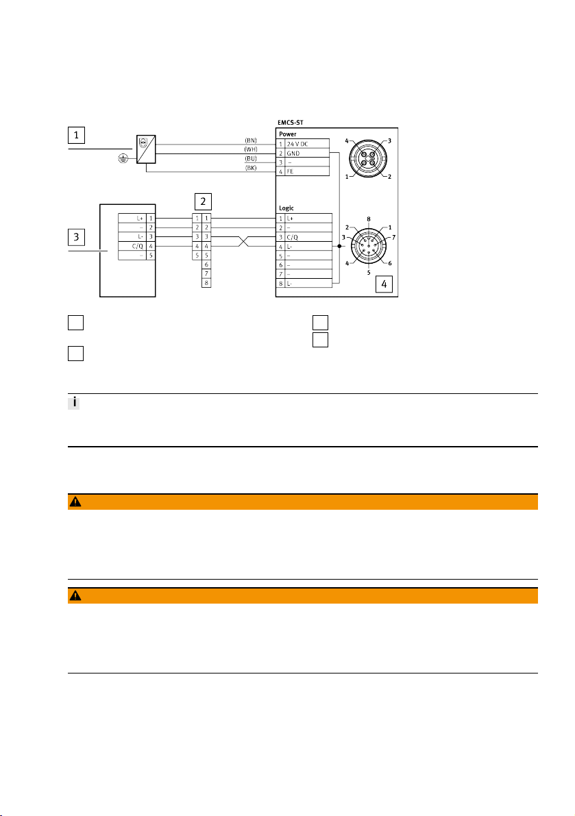
1. Connect the cables to the [Logic] and [Power] connections of the integrated drive EMCS-ST. Do not
connect pin3 at the [Power] terminal to high or low potential.
2. Connect cables to the controller or IO-Linkmaster and to the PELV fixed power supply units.
9Festo — ERMS — 2019-07
Page 10
Installation
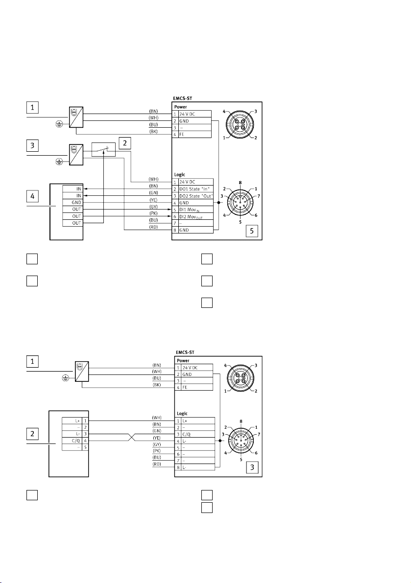
Wiring diagram: DIO operation (digital I/O)
– Reset (optional)
1
PELV fixed power supply unit for power supply 24 V DC
2
Reset button for acknowledging an error and
triggering a restart (optional)
Fig. 7 Wiring diagram: DIO operation (digital I/O)
Wiring diagram: IO-Link operation
1
PELV fixed power supply unit for power supply 24 V DC
Fig. 8 Wiring diagram: IO-Link operation
3
PELV fixed power supply for logic voltage
supply 24 V DC
4
Higher-level open-loop control (controller)
with digital I/O
5
EMCS-ST
2
IO-Link master with IO-Link interface
3
EMCS-ST
10 Festo — ERMS — 2019-07
Page 11
Commissioning
Wiring diagram: IO-Link operation with adapter NEFC
1
PELV fixed power supply unit for power supply 24 V DC
2
Adapter NEFC
Fig. 9 Wiring diagram: IO-Link operation with adapter
Core colours of Festo cables:
BK=black, BN=brown, BU=blue, GN=green, GY=grey, PK=pink, WH=white, YE=yellow
3
IO-Link master with IO-Link interface
4
EMCS-ST
9 Commissioning
WARNING!
Risk of injury due to unexpected movement of components.
• Protect the positioning range from unwanted intervention.
• Keep foreign objects out of the positioning range.
• Perform commissioning with low dynamic response.
WARNING!
Severe, irreversible injuries from accidental movements of the connected actuator technology.
Unintentional movements of the connected actuator technology can result from exchanging the connecting cables of a servo drive or between servo drives.
• Before commissioning: All cables must be correctly assigned and connected.
11Festo — ERMS — 2019-07
Page 12
Commissioning
WARNING!
Danger of burns from hot housing surfaces.
Metallic housing parts can reach high temperatures during operation.
Contact with metal housing parts can cause burn injuries.
• Do not touch metallic housing parts.
• After the power supply is switched off, let the device cool down to room temperature.
• A new homing is only necessary if the reference end position Ref or the useful range is changed.
• When homing, the Start Press Position Pos
is equated with the new end position Lim
Start Press
Out
9.1 Commissioning "DIO operation (digital I/O)"
Preparation
1. Check the mounting of the drive system.
2. Check wiring of power supplies [Power], [Logic] and digital I/O (DIO) [Logic].
Processing
1. Switch on power voltage.
2. Switch on logic voltage.
3. Wait for initialisation until LED "C/Q" lights yellow.
4. Parameterise (optional): Velocities (Speed In/Speed Out), Force/Torque (Force), Reference End
Position Ref (Reference) or Start Press Position Pos
è 10.3 Display and operating components (HMI)
è Tab. 5 Parameterise and control homing
è Tab. 6 Parameterise and control end-to-end operation
Start Press
(Start Press).
.
The drive system is ready for operation and can be controlled via the DIO control interface (digital I/O).
With the first motion task and after each restart, the position of the reference end position "Ref" is reinitialised (drive first moves to the reference end position "Ref" before the actual motion task is
executed), LED "C/Q" lights green.
12 Festo — ERMS — 2019-07
Page 13
Operation
9.2 Commissioning "IO-Link Operation"
Preparation
1. Check the assembly of the drive unit.
2. Check the wiring of the power supplies [Power] and the IO-Link interface [Logic].
3. Install the application software.
4. Open IODD file in the application software èwww.festo.com/sp.
Processing
1. Switch on power voltage.
2. Switch on logic voltage via IO-Link master.
3. Wait for initialisation until LED "C/Q" lights yellow.
4. Establish IO-Link connection with the drive system.
5. Parameterise (optional):
Reference endposition Ref (Reference), Velocities (SpeedIn/SpeedOut), Force, Start Press PositionPos
è Tab. 5 Parameterise and control homing
è Tab. 6 Parameterise and control end-to-end operation
The drive system is ready for operation and can be controlled via the IO-Link interface. With the first
motion task and after each restart, the position of the reference end position "Ref" is re-initialised
(drive first moves to the reference end position "Ref" independently of the motion task before the
actual motion task is executed), LED "C/Q" flashes green.
(PositionStartPress) or End positionLim
Start Press
(End PositionOut)
Out
10 Operation
WARNING!
Danger of burns from hot housing surfaces.
Metallic housing parts can reach high temperatures during operation.
Contact with metal housing parts can cause burn injuries.
• Do not touch metallic housing parts.
• After the power supply is switched off, let the device cool down to room temperature.
10.1 Master control
– Lowest priority: DIO operation (after Power ON and initialisation)
– Medium priority: IO-Link operation (after established IO-Link communication)
– Highest priority: HMI operation (unlocked pushbuttons)
13Festo — ERMS — 2019-07
Page 14
Operation
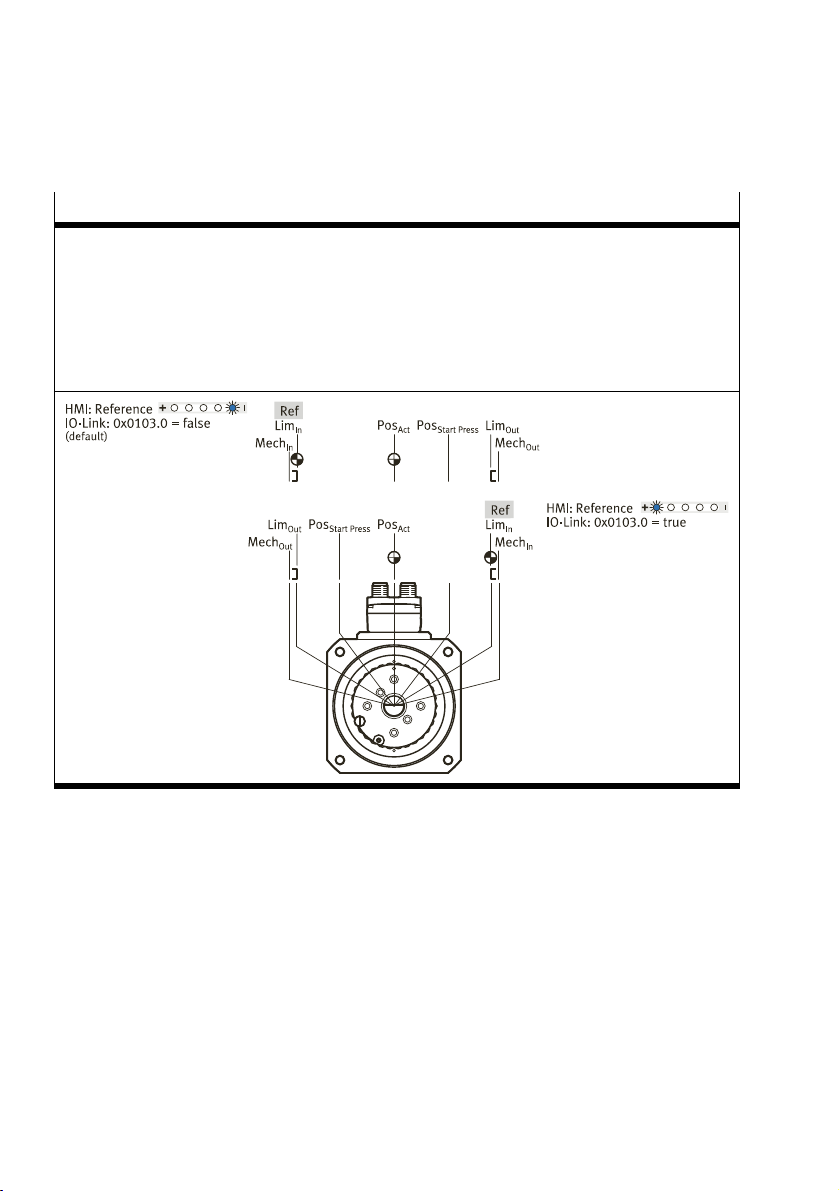
10.2 Dimension reference system
The correct positioning of the drive requires a defined dimension reference system.
Rotary drive system
– Ref: reference end position (reference point for LimIn, Lim
– left (default)
– right
– LimIn/Lim
– MechIn/Mech
– Pos
– Pos
: end positions
Out
: mechanical stops
Out
: current position
Act
: Start Press Position
Start Press
Tab. 4 Dimension reference system for rotary drive systems
Out
, Pos
and Pos
Act
Start Press
)
14 Festo — ERMS — 2019-07
Page 15
Operation
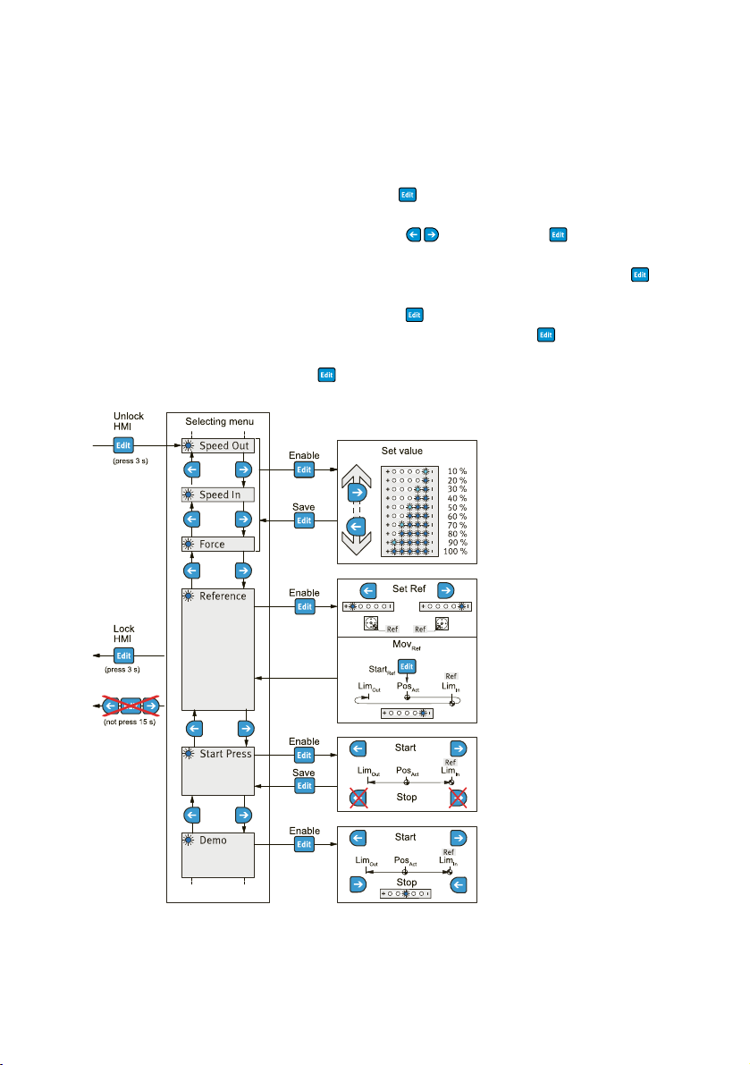
10.3 Display and operating components (HMI)
The display and operating components (HMI) can be used to perform the following functions in the
HMI menu:
– Unlock pushbutton actuators (Unlock HMI), 3s press
(Condition for IO-Link operation: IO-Link parameter 0x000C.4 = false)
– Select menu function with pushbutton actuators (selecting menu), press
– Parameterise setpoint values Speed Out, Speed In and Force
(Set value: 10, 20, ..., 100%of maximum value è 14 Technical data) and save (Save), press
– Parameterise the position of the reference end position Ref (Set Ref) and run the homing move-
ment Mov
– Start Press Run (Start/Stop) and Start Press Position Pos Save
– Execute Demo Run (Start/Stop)
– Lock pushbuttons (Lock HMI), 3s press or 15s no pushbutton entry
Ref
(Start
Ref
: Pos
èLimInèLim
Act
), press
Out
Start Press
, press.
Fig. 10 HMI menu
15Festo — ERMS — 2019-07
Page 16
Operation
10.4 Homing
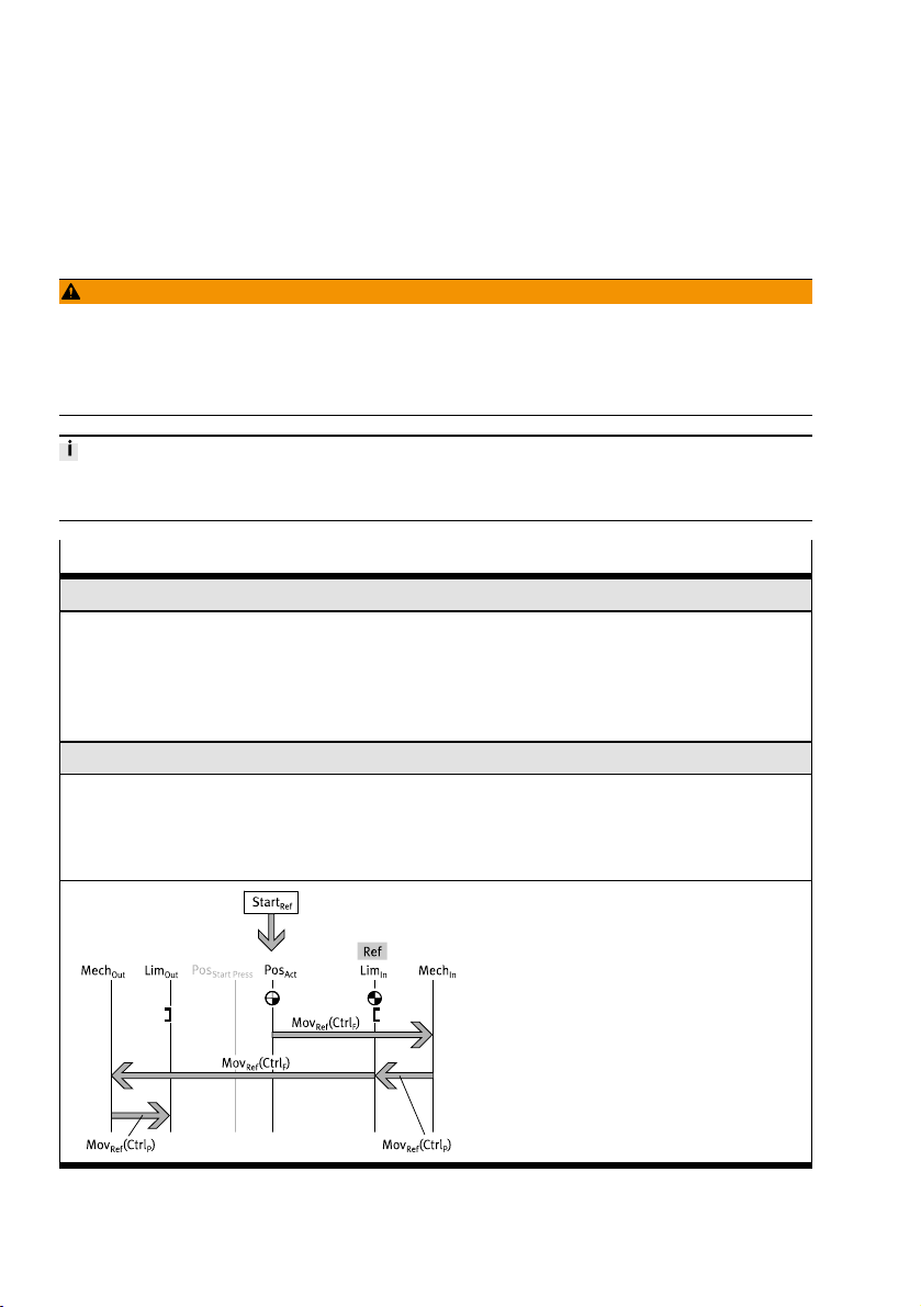
During homing, the positions of the mechanical stops MechIn/ Mech
culate the end positions LimIn (Ref)/Lim
for the dimension reference system.
Out
Before the homing run is carried out, the drive is de-energised for a required re-initialisation. Then the
power supply is restored and the homing process starts.
WARNING!
Risk of injury due to unexpected movement of components.
When starting the homing run, the drive is disconnected from the power supply for a short time. This
can cause unexpected movements of the connected mechanics and crush parts of the body.
• Bring moving parts of the connected mechanical system into a safe position.
• A new homing is only necessary if the reference end position Ref or the useful range is changed.
• When homing, the Start Press Position Pos
is equated with the new end position Lim
Start Press
Homing
Parameterise reference endposition "Ref"
HMI:
– Menu, Reference è 10.3 Display and operating components (HMI)
IO-Link (acyclic device data):
– left (default): 0x0103.0, reference=false
– right: 0x0103.0, reference=true
Control homing
HMI:
– Start
: menu, reference
Ref
è 10.3 Display and operating components
IO-Link (acyclic device data):
– Start
Ref
0x0104.0, Execute Mov
(HMI)
are determined in order to cal-
Out
:
=true
Ref
Out
.
Tab. 5 Parameterise and control homing
16 Festo — ERMS — 2019-07
Page 17
Operation
10.5 End-to-end operation
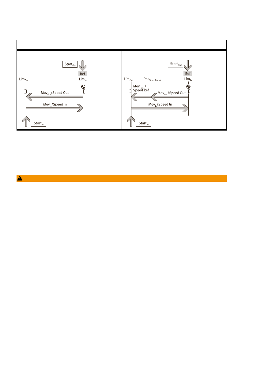
In end-to-end operation with or without press function, the unit can be moved between the end positions LimIn/ Lim
Each time the logic voltage is switched on, the position of the reference endposition Ref is re-initialised with speedRef with the first motion task. When moving to theLim
position is approached at theSpeedOut velocity.
End-to-end operation
Parameterise end-to-end operation
HMI:
– Speed Out, Speed In, Force and Start Press è 10.3 Display and operating components (HMI)
IO-Link (acyclic device data):
– Velocity Speed Out: 0x0101.0, Speed Out
– Velocity Speed In: 0x0100.0, Speed In
– Force/Torque: 0x0102.0, Force
– Start Press Position Pos
– End position Lim
Control end-to-end operation
DIO: IO-Link (cyclic process data):
.
Out
1)
2)
: 0x0105.0, Position Start Press [mm]
Start Press
: 0x0106.0, end position Out [mm]
Out
end position, theLim
Out
1)
1)
2)
3)4)
4)
Out
end
17Festo — ERMS — 2019-07
Page 18
Maintenance
End-to-end operation
Single end-to-end operation End-to-end operation with press function
1) 10, 20, ..., 100% of maximum value
2) Only required for end-to-end operation with press function
3) Reset
4) with each reference point "reference end position Ref"
Tab. 6 Parameterise and control end-to-end operation
11 Maintenance
WARNING!
Danger of crushing due to unexpectedly fast-moving loads and unintentional movements.
• Switch off power to the product.
• Safeguard the power supply from being switched on again unintentionally.
11.1 Disassembly
• Remove motor cables and retaining screws.
Observe transport information è 6 Transport.
11.2 Cleaning
• Clean the outside of the product with a soft cloth. Do not use aggressive cleaning agents.
18 Festo — ERMS — 2019-07
Page 19
Malfunctions
12 Malfunctions
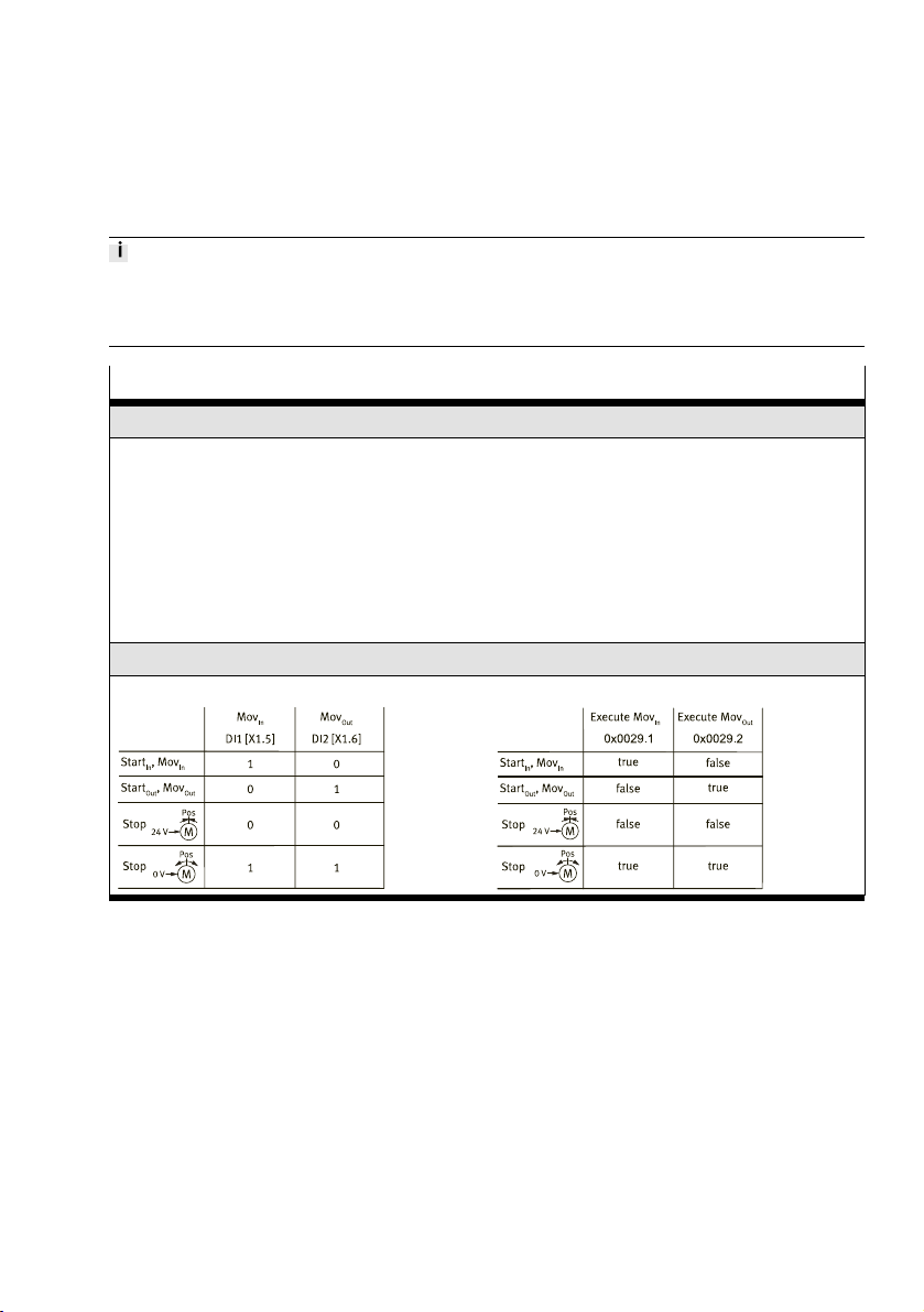
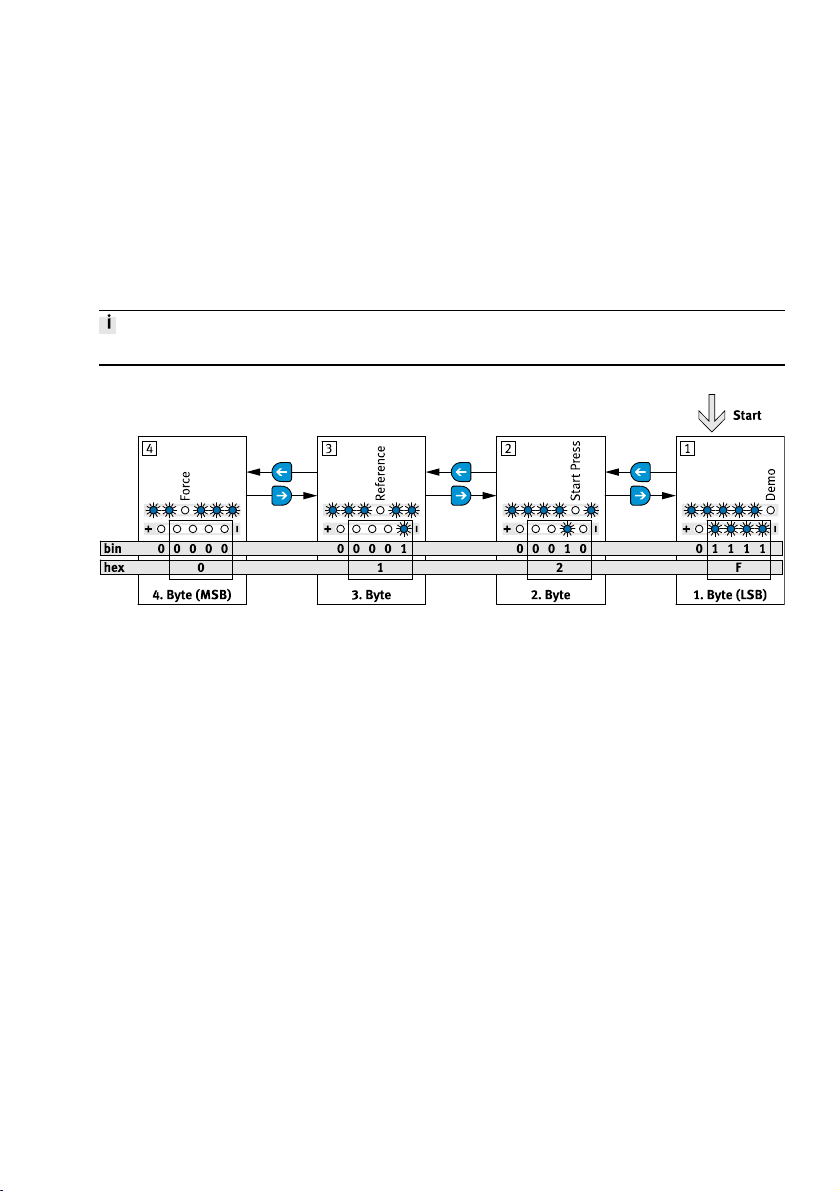
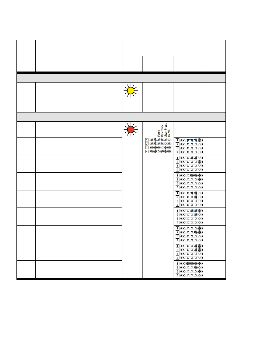
Diagnostic messages "Warnings and Errors" are displayed via the LED displays C/Q, menu and parameters.
In DIO mode, errors are reported to the controller via the sensor signal combination "1–1".
Errors can be reset as follows:
– DIO mode èreset of logic voltage
– IO-Link operatingèparameter "Quit Error" (0x0029.3 or 0x0107.0)
The first error that occurred is always displayed.
Fig. 11 Display of diagnostic messages (example)
19Festo — ERMS — 2019-07
Page 20
Malfunctions
Error
code
hex
(dec)
Warning
z
Error
z
0x000F
(15)
0x0016
(22)
0x0017
(23)
0x0026
(38)
0x0027
(39)
Description LED displays Event
code
C/Q Menu Parameter (IO-
Link)
Warnings
z z
0x...
Detailed information èDescription of
integrated drive EMCS-ST
yellow
on
Common device error
èContact Festo
I2t monitoring output stage error 0x1805
Logic voltage undersupply
1)
red on
…
0x1000
0x1804
Logic voltage oversupply 0x1803
Load voltage undersupply or not con-
0x1802
nected
Load voltage oversupply 0x1801
0x0031
Device undertemperature
0x4000
(49)
0x0033
Device overtemperature
(51)
0x012F
IO-Link connection lost
z
(303)
1) This error can only be acknowledged by a restart.
Tab. 7 Diagnostic messages "Warnings and Errors"
20 Festo — ERMS — 2019-07
Page 21
Disposal
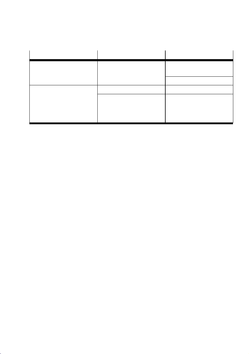
12.1 Fault clearance
Malfunction Possible cause Remedy
Squeaking noises, vibrations or
the drive is not running
smoothly
Tab. 8 Fault clearance
Tensions
Loads too high Reduce payload/torques.Rotary table does not move
Retaining screws of the tool too
long
Change arrangement of the
tool/payload.
Change the travel velocity.
Observe the maximum screw-in
depth
è 7.2 Mounting attachment
component.
12.2 Repair
Send the product to the Festo repair service for repair.
13 Disposal
Dispose of the product and packaging at the end of its useful life through environmentally friendly
recycling in accordance with applicable regulations.
21Festo — ERMS — 2019-07
Page 22
Technical data
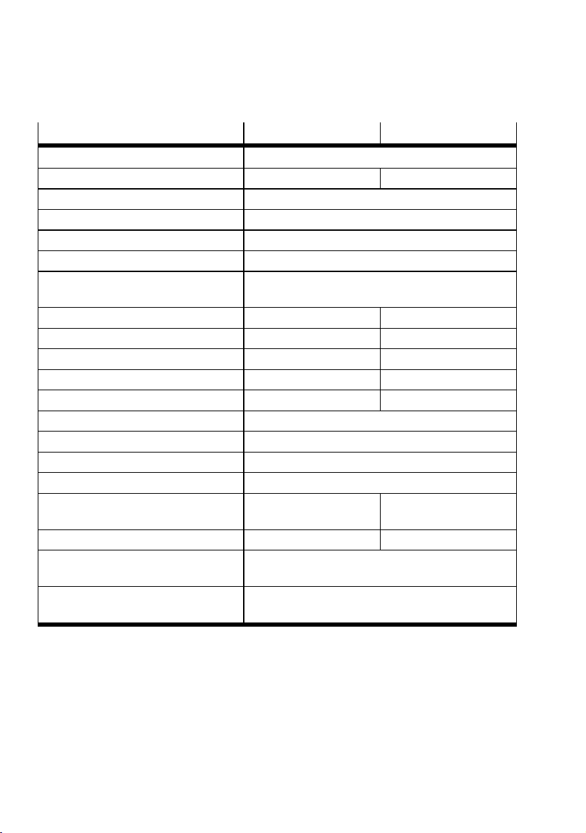
14 Technical data
Size 25 32
Mounting position Any
Product weight [kg] 1.47 2.30
Ambient temperature [°C] 0…+50
Storage temperature –20…+60
Relative humidity [%] 0…85 (non-condensing)
Degree of protection IP40
CE marking
è Declaration of Conformity
Max. dynamic axial force [N] 350 450
Max. dynamic radial force [N] 450 550
Max. rotational speed
1)
[rpm] 150 100
Velocity "SpeedPress" [rpm] 3 2
Max. torque
2)3)
[Nm] 2.7 5.6
Acceleration/deceleration [rad/s2] 140
Observe duty cycle
Distance stop/end position
4)
5)
[%] 100
[°] 2
Torsional backlash (new) [°] 0.2
Permissible mass moment of
[kgcm2] 65 164
inertia
Repetition accuracy [°] ±0.05 ±0.1
Vibration resistance in accordance with EN 61800-2 and EN 61800-5-1
Shock resistance in accordance with EN 61800-2
1) Maximum value for Speed In/Speed Out at level10
2) Maximum value for force at stage10
3) The force is controlled and evaluated by regulating the motor current. Depending on the mechanism of the drive, a torque level can be
determined from the level of current measured. The target is set as a percentage of the rated motor current and may differ from the
actual force at the rotary drive. In the case of low set force levels, the influence of friction in the system on the running behaviour and
the actual force on the rotary drive must also be taken into account.
4) derating
5) Distance (MechIn –LimIn or MechOut –LimOut)
Tab. 9 Technical data ERMS
In accordance with EU EMC Directive
In accordance with EU RoHS
Severity level1
Severity level1
22 Festo — ERMS — 2019-07
Page 23
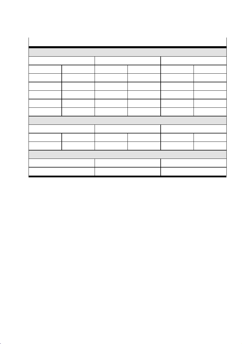
Technical data
Features of severity level (SL)
Vibration load
Frequency range [Hz] Acceleration [m/s2] Deflection [mm]
SL1 SL2 SL1 SL2 SL1 SL2
2…8 2…8
8…27 8…27 10 10
27…58 27…60
58…160 60…160 20 50
160…200 160…200 10 10
– –
– –
±3.5 ±3.5
– –
±0.15 ±0.35
– –
– –
Shock load
Acceleration [m/s2] Duration [ms] Shocks per direction
SL1 SL2 SL1 SL2 SL1 SL2
±150 ±300 11 11 5 5
Continuous shock load
Acceleration [m/s2] Duration [ms] Shocks per direction
±150 6 1000
Tab. 10 Features of severity level (SL)
23Festo — ERMS — 2019-07
Page 24

Reproduction, distribution or sale of this document or communication of its contents to others without express authorization is
prohibited. Offenders will be liable for damages. All rights
reserved in the event that a patent, utility model or design patent
is registered.
Copyright:
Festo AG & Co. KG
Ruiter Straße 82
73734 Esslingen
Germany
Phone:
+49 711 347-0
Internet:
www.festo.com
 Loading...