

Page 1
EMMB-AS
Servo motor
Instructions| Operating
8101200
2019-04
[8101202]
5.2 Product design
Festo AG & Co. KG
Ruiter Straße 82
73734 Esslingen
Germany
+49 711 347-0
www.festo.com
8101200
Translation of the original instructions
1 About this document
1.1 Applicable documents
All available documents for the product èwww.festo.com/pk.
• Comply with the assembly instructions for the attachment elements.
1.2 Product version
This documentation describes the following product versions:
EMMB-AS-...-... Product version
K Featherkey
S Absolute encoder, single-turn
M Absolute encoder, multi-turn
B Holding brake
Tab. 1 Product version
2 Safety
2.1 Safety instructions
– Observe labelling on the product.
– Prior to assembly, installation and maintenance work: Switch off power sup-
ply, ensure that it is off and secure it against being switched back on.
– Store the product in a cool, dry, UV-protected and corrosion-protected envir-
onment. Ensure that storage times are kept to a minimum.
– Observe tightening torques. Unless otherwise specified, the tolerance
is±20%.
2.2 Intended use
The motor is intended to be used for driving positioning systems.
2.3 Foreseeable misuse
The holding brake must not be used for braking the motor.
2.4 Area of application and approval
In combination with the UL inspection mark on the product, the information in this
section must also be observed in order to comply with the certification conditions
of Underwriters Laboratories Inc. (UL) for USA and Canada.
UL approval information
Product category PRHZ2 (USA) or PRHZ8 (Canada)
File number E342973
Standards taken into account UL 1004-1/-6, C22.2 No.100
UL inspection mark
Tab. 2 Approval information
3 Additional information
– Accessories èwww.festo.com/catalogue.
4 Service
Contact your regional Festo contact person if you have technical questions
èwww.festo.com.
5 Product overview
5.1 Function
The product is a permanently excited, electrodynamic, brushless servo motor. The
motor is equipped with an encoder. The encoder supplies motor data, speed and
position signals to a higher-order servo drive/motor controller in the form of digital signals.
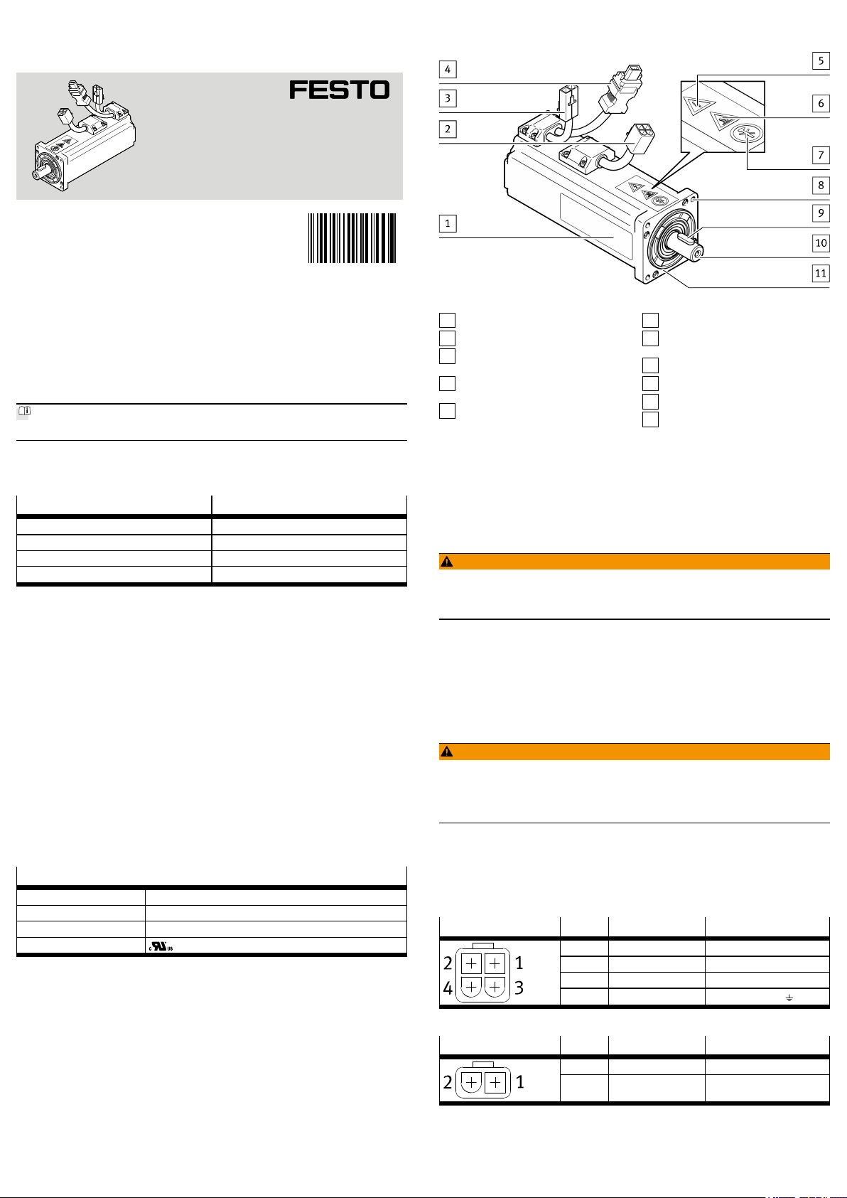
Product labelling
1
Electrical connection: motor
2
Electrical connection: holding
3
brake (optional)
Electrical connection: absolute
4
encoder
Warning: dangerous electrical
5
voltage
Warning: hot surface
6
Note: no mechanical impacts per-
7
mitted
Through-hole for mounting
8
Featherkey (optional)
9
Motor shaft
10
Motor flange
11
Fig. 1 Product design EMMB-AS
6 Transport
Take product weight into account è 13 Technical data
7 Mounting
7.1 Installation
WARNING!
Risk of injury due to unexpected movement of components.
• Bring moving parts of the connected mechanical system into a secure position (e.g.move into the lower end position).
Mount motor
1. Clean motor shaft. The motor shaft must be dry and free of grease.
2. Fasten the motor to the driven mechanical system è accompanying documents.
7.2 Mounting accessories
– Use Festo accessories èwww.festo.com/catalogue.
8 Electrical installation
WARNING!
Risk of injury due to electric shock.
• Switch off power supply prior to assembly and installation work; ensure that
it is off and secure it against being switched back on.
Cancelling the enable signal is not sufficient.
1. Connect cable to the servo drive èObserve documentation for cable and
servo drive.
2. Connect cable to the motor.
– Conductor cross-section must be adequately dimensioned.
– Use screened cables.
Motor plug, 4-pin Pin Identifier Function
1 U Motor phase U
2 V Motor phase V
3 W Motor phase W
4 PE Protective earthing
Tab. 3 Plug for motor
Connecting plug, 2-pin Pin Identifier Function
1 BR+ Holding brake, 24VDC
2 BR– Holding brake, reference
potential 0V
Tab. 4 Plug for holding brake
Page 2
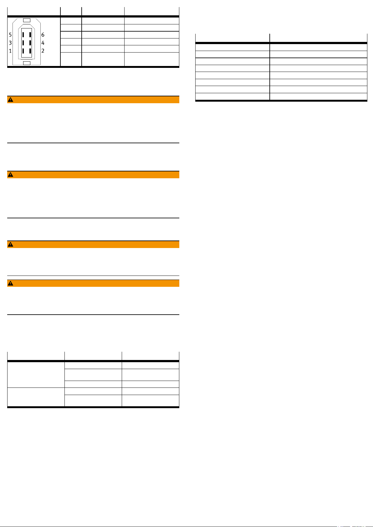
Encoder plug, 6-pin Pin Identifier Function
1 V
2 GND Weight
3 BAT+ Supply voltage battery
4 BAT– Battery earth
5 SD+ positive signal
6 SD– negative signal
1) only with EMMB-AS-...-...M with absolute encoder multi-turn
CC
Supply voltage 24VDC
1)
1)
Tab. 5 Plug for absolute encoder
9 Commissioning
WARNING!
Risk of injury due to unexpected movement of components.
• When releasing the holding brake, secure the driven mechanical system to
prevent unintended movement.
• Deenergise the motor before releasing the holding brake manually.
• Before setting the enable signal, protect the traversing range of the driven
mechanical system from access.
– Commission the motor together with the servo drive èDocumentation for
servo drive.
10 Operation
WARNING!
Danger of burns from hot housing surfaces.
Metallic housing parts can reach high temperatures during operation.
Contact with metal housing parts can cause burn injuries.
• Do not touch metallic housing parts.
• After the power supply is switched off, let the device cool down to room temperature.
13 Technical data
Technical data for the product:
1. Internet èwww.festo.com/pk.
2. Product labelling 1 with the following values:
Identifier
IPxx Degree of protection
U
n
M
M
I
N
I
0
Class F Temperature class F (155°C)
1) all data in accordance with EN60034-1: 2010-10
2) The product is intended for use in industrial environments. Measures for interference suppression may be
1)2)
DC
N
N
0
required in residential areas. The product may generate high frequency malfunctions, which may require
interference suppression measures in residential areas.
[V] Nominal operating voltage DC
[rpm] Nominal rotary speed
[Nm] Nominal torque
[Nm] Stall torque
[A] Nominal current
[A] Continuous stall current
Description
Tab. 7 Designations on the product labelling
11 Maintenance
11.1 Disassembly
WARNING!
Risk of injury due to electric shock.
• Switch off power supply prior to assembly and installation work; ensure that
it is off and secure it against being switched back on.
Cancelling the enable signal is not sufficient.
WARNING!
Risk of injury due to unexpected movement of components.
• Bring moving parts of the connected mechanical system into a secure position (e.g. for vertical installation, move the slide into the lower end position).
• Only then should you disconnect the motor from the mechanical system.
11.2 Cleaning
Before cleaning, the product must be cooled down to below 40°C.
Clean the outside of the product with a soft cloth as required. Cleaning agents
include all non-abrasive media.
11.3 Fault clearance
Fault description Cause Remedy
Motor shaft does not turn.
tion or vibrates.
Excessive load Reduce load.
Servo drive has not yet been
enabled.
Holding brake is active. Release holding brake.
Cabling error Check and correct cabling.Motor turns in the wrong direc-
Controller parameter is incorrect.
Check signals.
Check and correct controller
parameter.
Tab. 6
11.4 Repair
Send the product to the Festo repair service for repair.
12 Disposal
Dispose of the product and packaging at the end of its useful life through environmentally friendly recycling in accordance with applicable regulations.
 Loading...