

Page 1
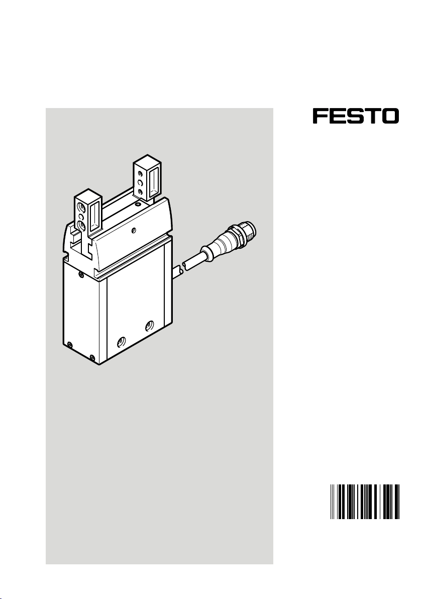
EHPS-...-LK
Parallel gripper
Instructions| Operating
8107761
8107761
2019-08
[8107763]
Page 2

Translation of the original instructions
IO-Link® is a registered trademark of its respective trademark holder in certain countries.
2 Festo — EHPS-...-LK — 2019-08
Page 3

Table of contents
1 About this document................................................................................................... 5
1.1 Further applicable documents...................................................................................... 5
1.2 Product labelling.......................................................................................................... 5
2 Safety........................................................................................................................... 5
2.1 Safety instructions........................................................................................................ 5
2.2 Intended use................................................................................................................ 5
2.3 Training of qualified personnel..................................................................................... 6
3 Additional information................................................................................................ 6
4 Service..........................................................................................................................6
5 Product overview......................................................................................................... 6
5.1 Function....................................................................................................................... 6
5.2 Design........................................................................................................................... 7
6 Mounting..................................................................................................................... 7
6.1 Preparing the gripper fingers........................................................................................ 7
6.2 Mounting the gripper fingers........................................................................................ 8
6.3 Mounting the gripper.................................................................................................... 9
6.4 Mounting accessories................................................................................................... 10
7 Installation.................................................................................................................. 10
7.1 Electrical installation.................................................................................................... 10
8 Commissioning............................................................................................................ 11
8.1 Processing.................................................................................................................... 12
9 IO-Link Interface description....................................................................................... 12
9.1 General information on the IO-Link............................................................................... 13
9.2 General specification IO-Link........................................................................................ 13
9.3 Communication functions............................................................................................. 14
9.4 Identification parameters............................................................................................. 15
9.5 IO-Link Standard parameters and commands............................................................... 15
9.6 Process Data OUT......................................................................................................... 16
9.6.1 Use cases................................................................................................................17
9.7 Process Data IN............................................................................................................ 18
9.7.1 Description "StatusWord"......................................................................................19
9.8 Device-specific parameters........................................................................................... 19
9.9 Commissioning............................................................................................................. 24
9.10 Datastorage.................................................................................................................. 24
9.11 System Commands....................................................................................................... 24
9.12 Fault clearance IO-Link................................................................................................. 25
10 Maintenance................................................................................................................ 28
10.1 Safety............................................................................................................................ 28
10.2 Cleaning....................................................................................................................... 28
10.3 Lubrication................................................................................................................... 28
3Festo — EHPS-...-LK — 2019-08
Page 4

11 Malfunctions................................................................................................................ 28
11.1 Diagnostics....................................................................................................................28
11.2 Fault clearance.............................................................................................................. 30
11.3 Repair............................................................................................................................31
12 Disassembly.................................................................................................................31
13 Disposal........................................................................................................................32
14 Technical data.............................................................................................................. 32
14.1 Technical data, general..................................................................................................32
14.2 Characteristic curves..................................................................................................... 33
4 Festo — EHPS-...-LK — 2019-08
Page 5
About this document
1 About this document
1.1 Further applicable documents
All available documents for the product èwww.festo.com/pk.
1.2 Product labelling
Warning symbols on the product
Symbol Meaning
General warning indicator:
The symbol means a hazardous area and that the operating instructions must be read
and observed.
Tab. 1 Warning symbols on the product
2 Safety
2.1 Safety instructions
– Observe labelling on the product.
– Prior to assembly, installation and maintenance work: Switch off power supply, ensure that it is
off and secure it against being switched back on.
– Store the product in a cool, dry, UV-protected and corrosion-protected environment. Ensure that
storage times are kept to a minimum.
– Observe tightening torques. Unless otherwise specified, the tolerance is±20%.
– The occurrence of a failure could lead to unforeseeable movements if the gripper is connected
with the power supply. Only operate the gripper once protective measures have been taken
against mechanical threats to body parts.
– Contrary to specification IO-Link port class B without galvanic isolation between primary and sec-
ondary power supply. This can lead to malfunction or damage to the IO-Link Master and the con-
nected IO-Link devices and must be observed during wiring.
2.2 Intended use
The intended use of the product is to grip and hold payloads (workpieces) using custom-designed
gripper fingers attached by the customer.
The gripper fingers are not included in the delivery.
When not used as intended, the product-supported protection can be impaired.
5Festo — EHPS-...-LK — 2019-08
Page 6

Additional information
2.3 Training of qualified personnel
Installation, commissioning, maintenance and disassembly should only be conducted by qualified personnel. The qualified personnel must be familiar with installation of electrical control systems.
3 Additional information
– Accessories èwww.festo.com/catalogue.
4 Service
Contact your regional Festo contact person if you have technical questions èwww.festo.com.
5 Product overview
5.1 Function
The gripper has an integrated motor. The gripper mechanism converts the rotary motion of the motor
into a linear motion of the gripper jaws.
The gripper jaws move towards one another (closing) or apart (opening). Gripper fingers are fastened
to the gripper jaws.
The payload can be gripped in 2 ways:
– on the external contour (external gripping) when closing
– on the internal contour (internal gripping) when opening
The parallel gripper is controlled via an IO-Link interface.
6 Festo — EHPS-...-LK — 2019-08
Page 7
Mounting
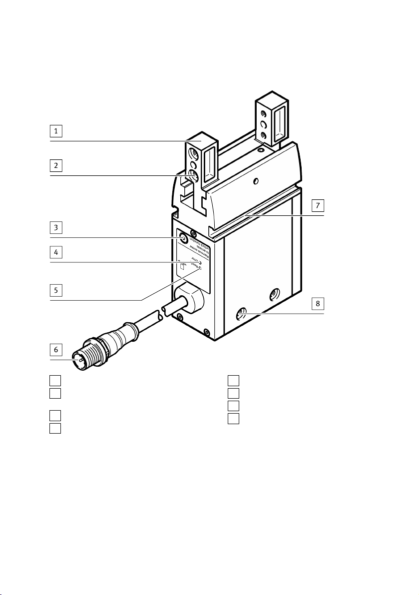
5.2 Design
1
Gripper jaws
2
Locating hole and thread for mounting the
gripper fingers
3
Plug screw
4
LED indicator (Error)
Fig. 1 Product design
5
LED indicator (Ready)
6
Electrical connection
7
Slot for proximity sensor
8
Locating hole and thread for mounting the
gripper
6 Mounting
6.1 Preparing the gripper fingers
Requirements for gripper fingers:
– Observe maximum permitted forces and torques on the gripper jaws è 14 Technical data.
– Use gripper fingers that are as short and lightweight as possible.
– Observe maximum length and weight è 14 Technical data.
– Produce gripper fingers that are suitable for the payload and type of gripping action.
7Festo — EHPS-...-LK — 2019-08
Page 8
Mounting
6.2 Mounting the gripper fingers
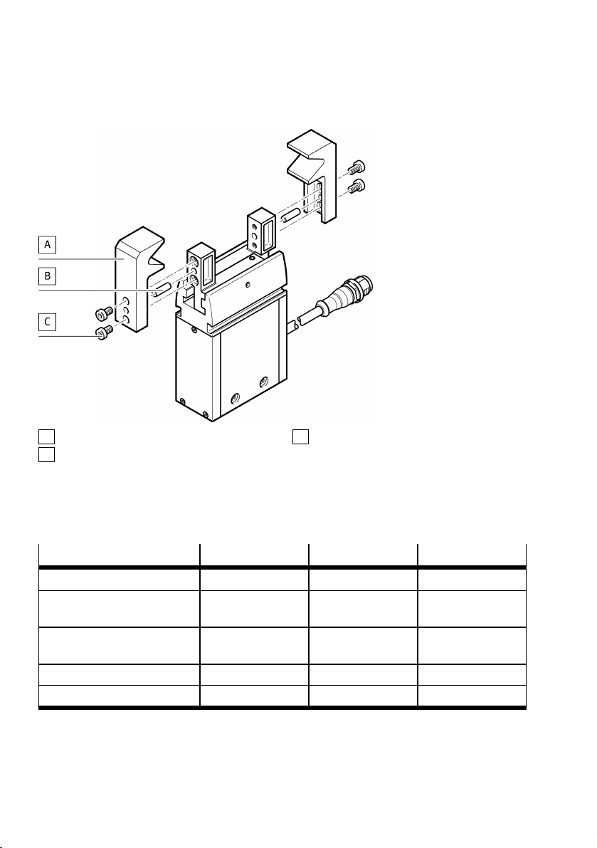
A
Gripper finger
B
Centring pin
C
Screw
Fig. 2 Gripper finger mounting
1. Press centring pin or centring sleeve into locating holes in the gripper jaws.
2. Position the prepared gripper fingers on the gripper jaws and secure with 2 screws on each. Fix
gripper jaws in place during mounting and comply with tightening torque.
Size 16 20 25
Screw M4 M4 M5
Centring hole for cent-
[mm] 7 7 9
ring sleeve [H8]
Centring hole for cent-
[mm] 3 4 4
ring pin [H8]
Jaw width [mm] 10 ±0.05 12 ±0.05 15 ±0.05
Tightening torque
1) Brace at gripper jaws
1)
[Nm] 2.9 2.9 5.9
Tab. 2 Gripper finger mounting, dimensions and tightening torque
8 Festo — EHPS-...-LK — 2019-08
Page 9
Mounting
6.3 Mounting the gripper
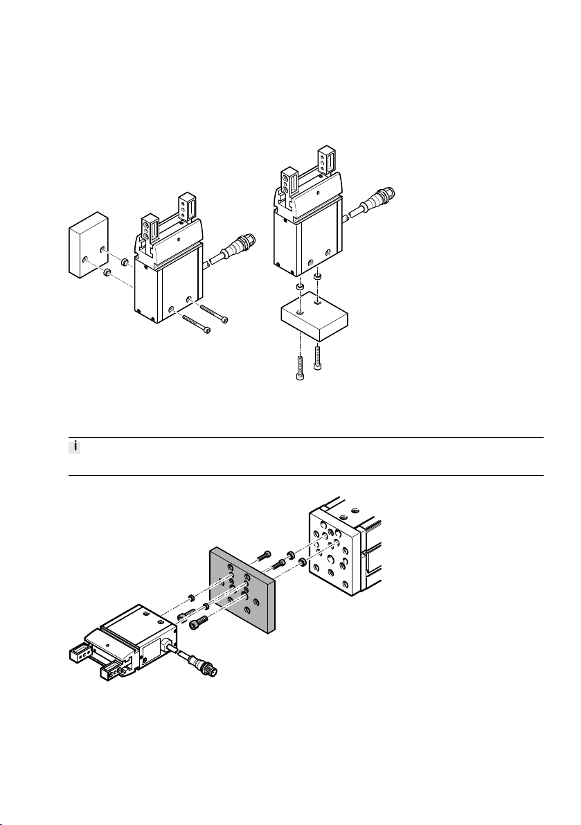
Through-hole mounting and direct mounting
Fig. 3 Through-hole mounting on the side, direct mounting underneath (also possible on the side)
Mounting with adapter kit
Adapter kits èwww.festo.com/catalogue.
Fig. 4 Mounting with adapter kit from underneath
9Festo — EHPS-...-LK — 2019-08
Page 10
Installation
NOTICE!
Accumulation of heat results from cramped installation situation.
Material damage or malfunction.
• Mount the product with sufficient space for heat dissipation.
1. Press 2 centring sleeves into the locating holes of the gripper.
2. Use the centring sleeves to position the gripper on the connecting surface.
3. Select screws in accordance with the type of mounting.
4. Tighten screws with the associated tightening torque.
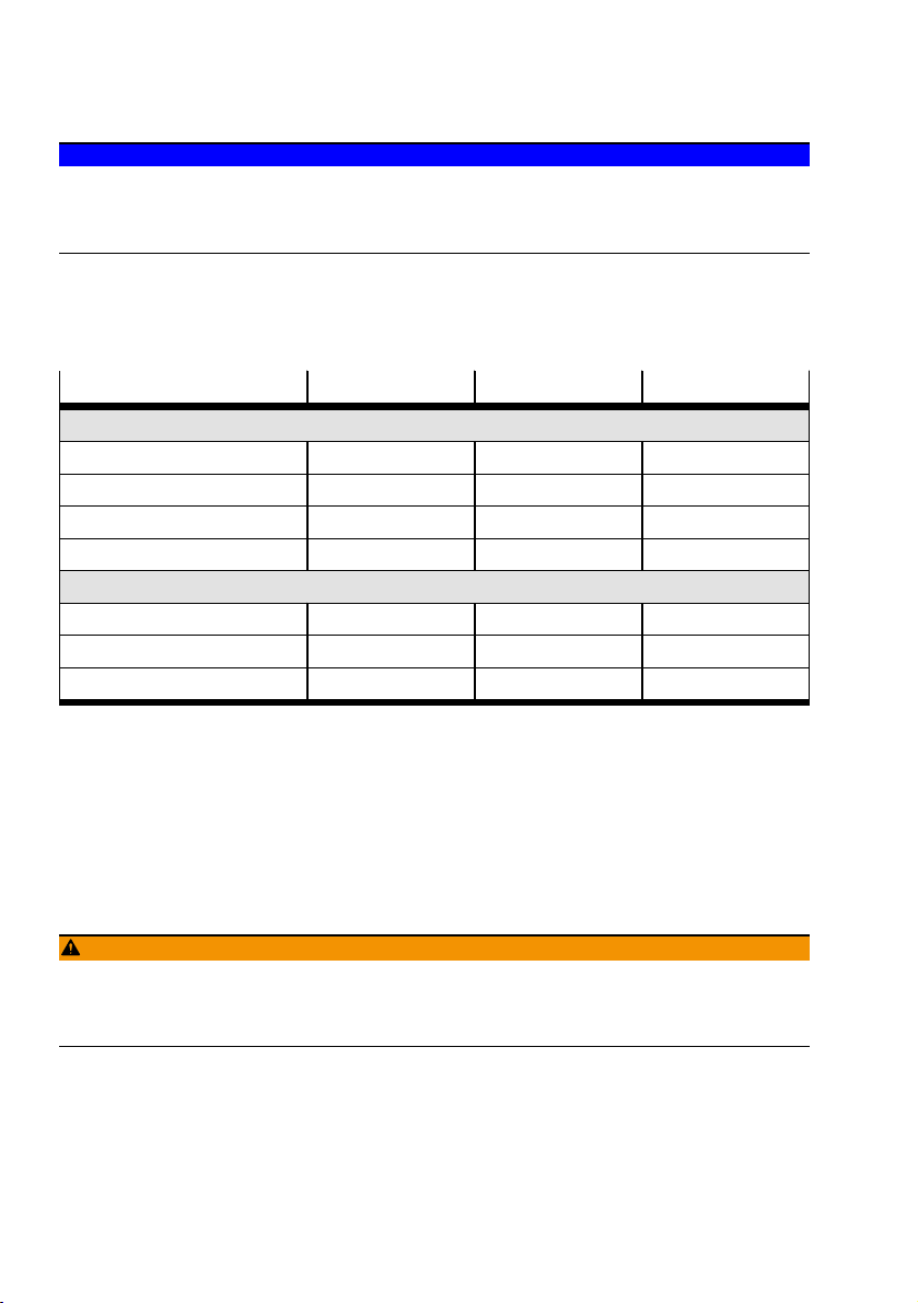
Size 16 20 25
Direct mounting
Screw M4 M4 M6
Max. screw-in depth [mm] 8 8 12
Centring hole [mm] 7 7 9
Tightening torque [Nm] 2.9 2.9 10
Through-hole mounting
Screw M3 M3 M4
Centring hole [mm] 7 7 9
Tightening torque [Nm] 1.2 1.2 2.9
Tab. 3 Mounting attachments and tightening torque
6.4 Mounting accessories
If required: use proximity sensor to sense the position of the gripper jaws in the slot.
Use only proximity sensors approved for the product.
7 Installation
7.1 Electrical installation
WARNING!
Risk of injury due to electric shock
• For the electric power supply, use only PELV or SELV circuits that ensure a reliable electric disconnection from the mains network.
10 Festo — EHPS-...-LK — 2019-08
Page 11
Commissioning
WARNING!
Risk of injury due to electric shock or burns.
The gripper does not offer any additional protection against unintended high currents in the supply
cables.
• The cross section of the supply cables should be designed to meet the maximum current value
that could occur in the event of a failure.
WARNING!
Danger of crushing.
The gripper fingers could move unintentionally and crush body parts.
• Do not reach into the movement range.
1. Switch off power to the controller and safeguard it from being switched on again unintentionally.
2. Use permissible connecting cable èwww.festo.com/catalogue.
3. Connect the parallel gripper to the controller at the connection plug.
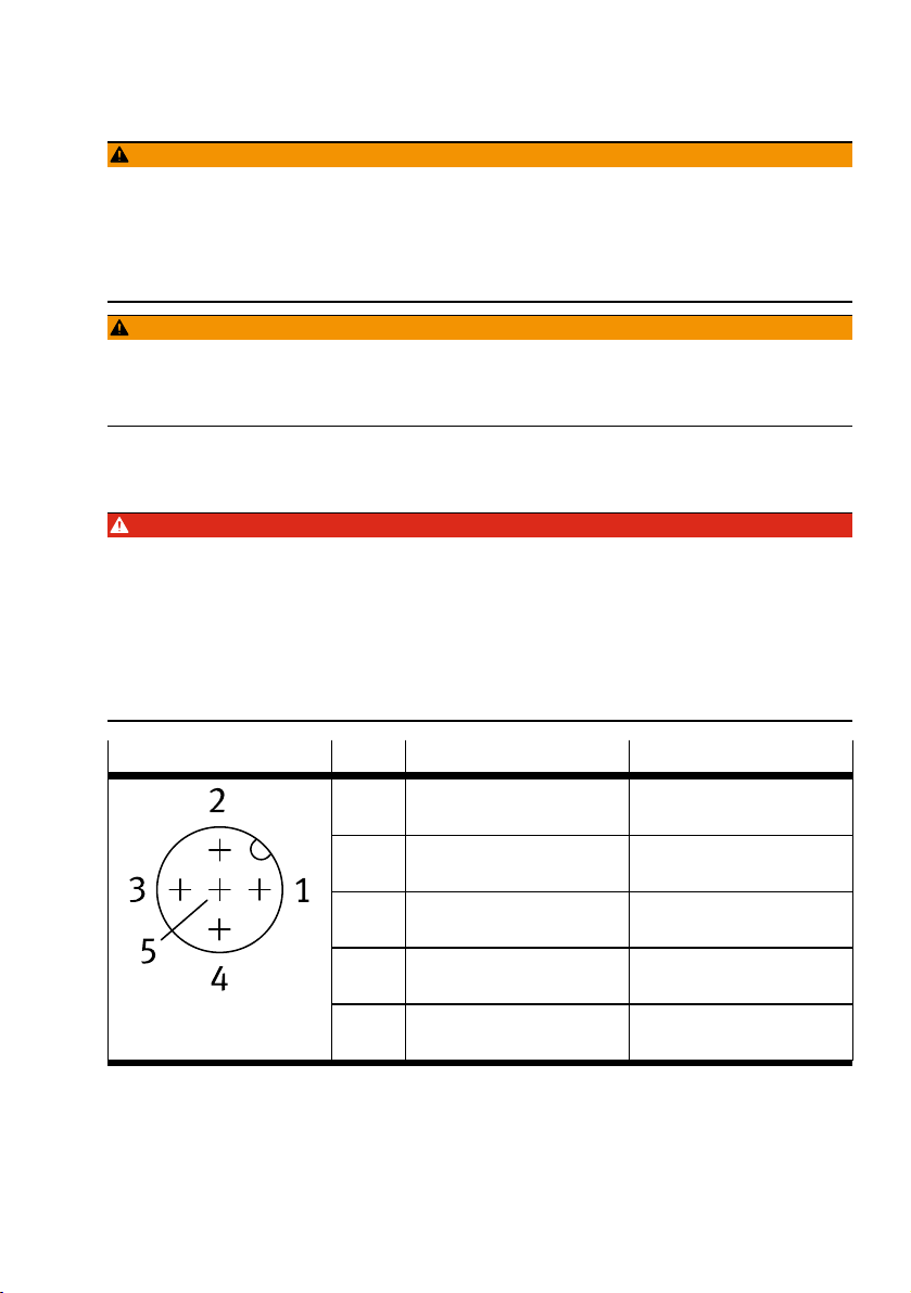
DANGER!
Danger of crushing due to unexpectedly moving loads and unintentional movements.
Contrary to specification IO-Link port class B without galvanic isolation between primary and secondary power supply. This can lead to malfunction or damage of the IO-Link Master and the connected IOLink devices.
• Connect pin 3 (L-) and pin 5 (N24) externally to avoid compensating currents via the gripper.
• When installing further IO-Link devices on the master, note that the actuator supply can only be
switched off via pin 2 (P24).
M12 plug (5-pin, A-coded) Pin
1)
1 (BN)
Connection Identifier
+18VDC…+30VDC Sensor: Supply voltage for
brown
2 (WH)
+24VDC (±10%) Actuator: supply voltage
white
3 (BU)
0VDC Sensor: supply voltage IO-
blue
4 (BK)
C/Q IO-Link Communication
black
5 (GY)
0VDC Actuator: supply voltage
grey
1) Wire colour with use of connecting cables according to accessories èwww.festo.com/catalogue
Tab. 4 Pin allocation
8 Commissioning
IO-Linkcommunication
Link communication
11Festo — EHPS-...-LK — 2019-08
Page 12

IO-Link Interface description
8.1 Processing
DANGER!
Danger of crushing due to unexpectedly moving loads and unintentional movements.
Contrary to specification IO-Link port class B without galvanic isolation between primary and secondary power supply. This can lead to malfunction or damage of the IO-Link Master and the connected IOLink devices.
• Connect pin 3 (L-) and pin 5 (N24) externally to avoid compensating currents via the gripper.
• When installing further IO-Link devices on the master, note that the actuator supply can only be
switched off via pin 2 (P24).
WARNING!
Danger of crushing.
The gripper fingers could move unintentionally and crush body parts.
• Do not reach into the movement range.
NOTICE!
Material damage due to incorrect or incomplete installation.
The following conditions must be fulfilled for commissioning:
• The system must be fully assembled.
• The electrical installation must be complete and checked.
9 IO-Link Interface description
• The associated device description file (IODD) èwww.festo.com/sp
• Detailed information on the IO-Link specification èwww.io-link.com
12 Festo — EHPS-...-LK — 2019-08
Page 13
IO-Link Interface description
9.1 General information on the IO-Link
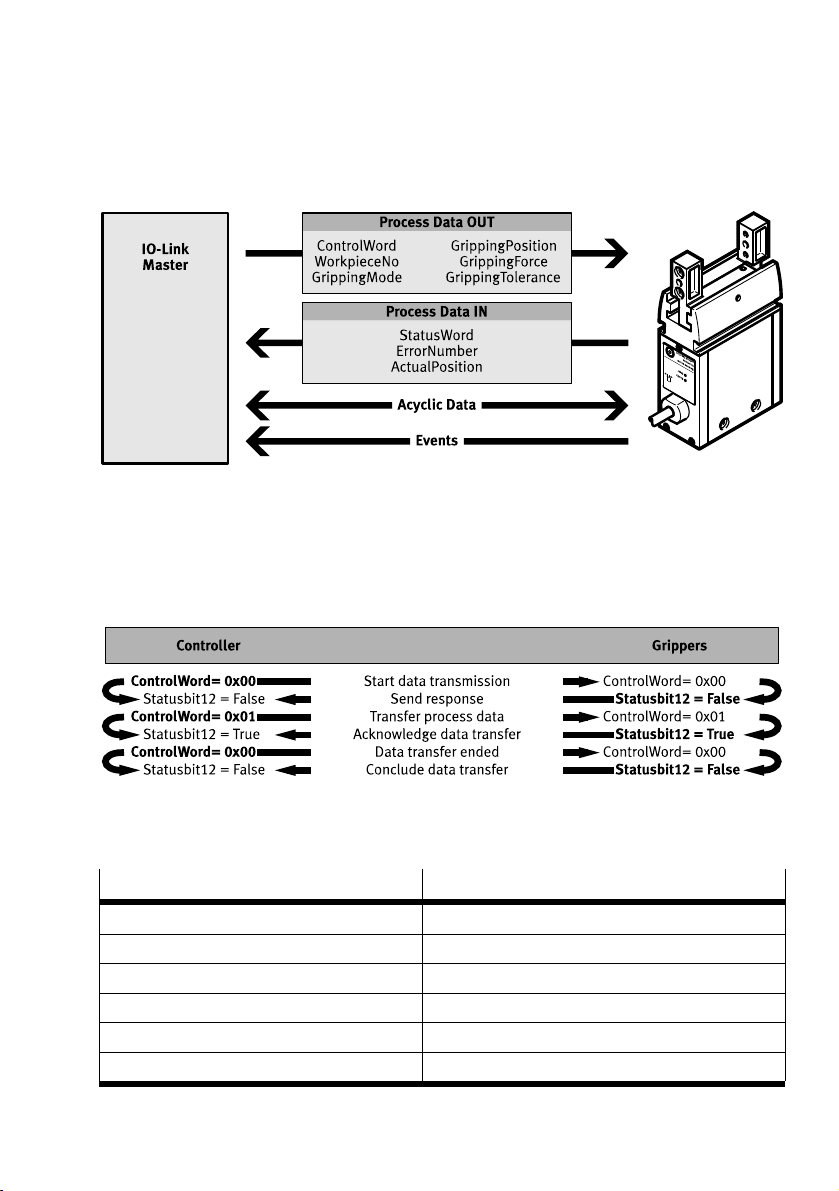
Data exchange
Fig. 5 Data exchange
Handshake
Data must be transferred between controller and gripper using the Handshake protocol. The data
receiver confirms data reception by setting a bit. Another command cannot be sent until the previous
data transfer has been completed.
Fig. 6 Handshake
9.2 General specification IO-Link
Feature Specification
Protocol IO-Link
IO-Link, protocol version Device V 1.1
IO-Link, communication mode COM3 (230.4 kbaud)
IO-Link, SIO mode support no
IO-Link, port class Device B
IO-Link, number of ports Device 1
13Festo — EHPS-...-LK — 2019-08
Page 14

IO-Link Interface description
Feature Specification
IO-Link, process data width OUT [Bytes] 8
IO-Link, process data content OUT [bit] 16 "ControlWord"
8 "GrippingMode"
8 "WorkpieceNo"
16 "GrippingPosition"
8 "GrippingForce"
8 "GrippingTolerance"
IO-Link, process data width IN [Bytes] 6
IO-Link, process data content IN [bit] 16 "StatusWord"
16 "ErrorNumber"
16 "ActualPosition"
IO-Link, service data content IN
[Bytes] 32 "ApplicationSpecificTag"
[bit] 16 "StatusWord"
16 "ErrorNumber"
32 "CycleCounter"
16 "Temperature"
16 "ControlWord"
[Bytes] 64 "ErrorMessage"
[bit] 16 "ErrorCount"
16 "ActualPosition"
16 "GrippingPosition"
8 "WorkpieceNo"
8 "GrippingMode"
8 "GrippingTolerance"
8 "GrippingForce"
40 "WorkpieceSet"
IO-Link, min. cycle time [ms] 5
IO-Link, data memory required [Kbyte] < 0.5
1) Copy of the process data
2) data currently used
Tab. 5 General specification IO-Link
1)
1)
1)
1)
2)
2)
2)
2)
2)
9.3 Communication functions
Feature Specification
Preoperate M-sequence type _1_V, (8 Byte On-request Data)
Operate M-sequence type _2_V, (8 Byte OUT; 6 Byte IN; 2
Byte On-request Data)
14 Festo — EHPS-...-LK — 2019-08
Page 15
IO-Link Interface description
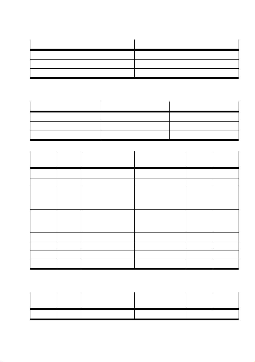
Feature Specification
ISDU supported
Data Storage supported
Block Parameterization supported
Tab. 6 Communication functions
9.4 Identification parameters
EHPS-...-A-LK Device ID [dec/hex] Vendor ID [dec/hex]
16 49/0x000031 333/0x014D
20 50/0x000032 333/0x014D
25 51/0x000033 333/0x014D
Tab. 7 Identification parameters
Index Sub index Name Value (example) Length
[byte]
0x0010 0 "Vendor Name" Festo AG & Co. KG 64 String
0x0011 0 "Vendor Text" www.festo.com 64 String
0x0012 0 "Product Name" EHPS-16-A-LK
EHPS-20-A-LK
EHPS-25-A-LK
0x0013 0 "Product ID" 8103809
8103810
8103811
0x0014 0 "Product Text" parallel gripper 64 String
0x0015 0 "Serial Number" KNP00002 16 String
0x0016 0 "Hardware Revision" REV01 64 String
0x0017 0 "Firmware Revision" V1.0.0 64 String
Tab. 8 Identification parameters
64 String
64 String
Format
9.5 IO-Link Standard parameters and commands
Index Sub index Name Value Length
[byte]
0x0020 0 "ErrorCount" Example: 123456 16 UIntegerT
Tab. 9 IO-Link Standard parameters and commands
Format
15Festo — EHPS-...-LK — 2019-08
Page 16
IO-Link Interface description
9.6 Process Data OUT
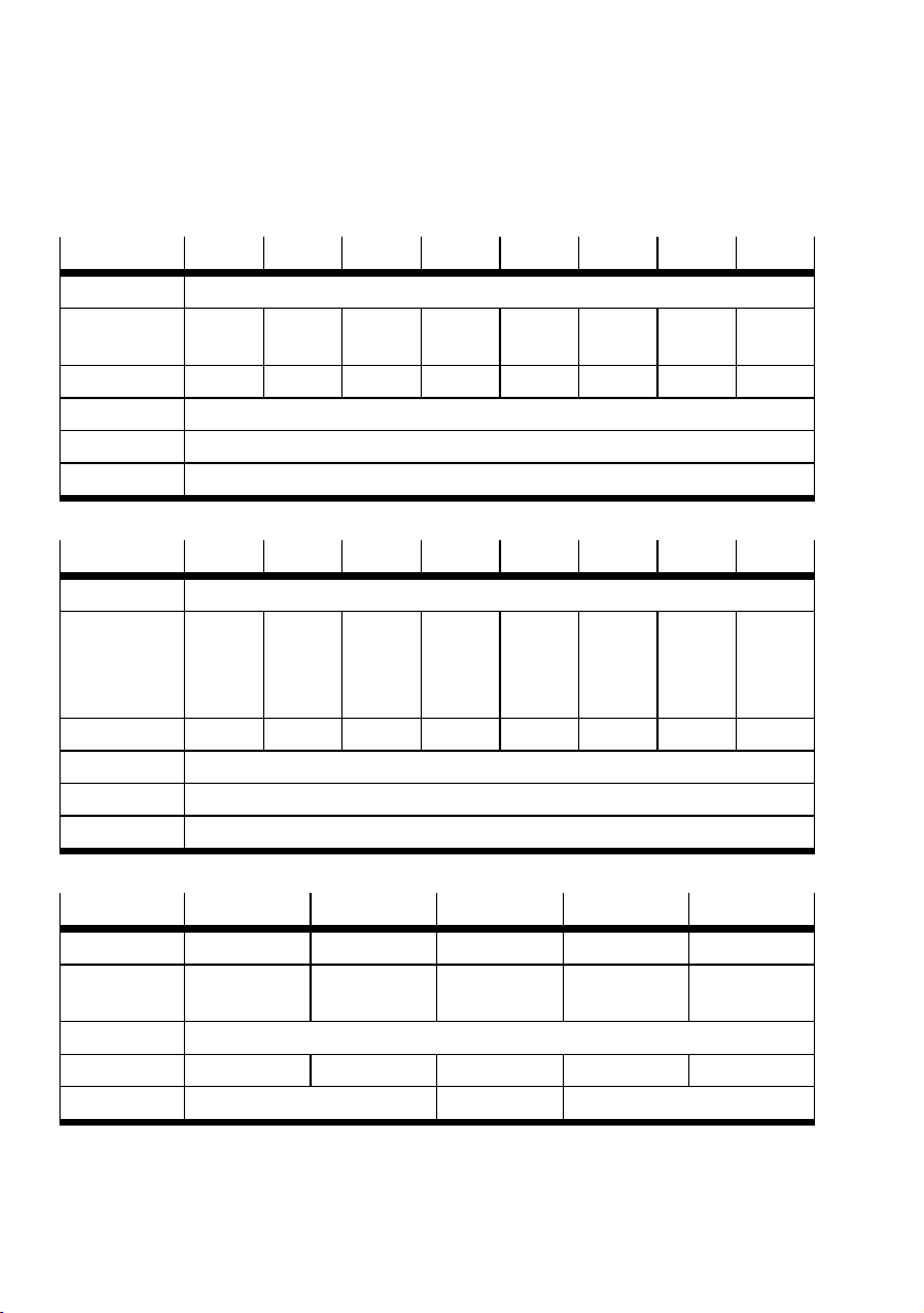
The gripper can only be controlled with the cyclically transmitted process data. A maximum of 1 bit
only may be set in the "ControlWord".
Bit 63 62 61 60 59 58 57 56
Process data "ControlWord"
Data content "Rese-
tError"
Decimal 32768
Index 0x0029
Sub index 1
Data type UIntegerT16
Tab. 10 Process data OUT
Bit 55 54 53 52 51 50 49 48
Process data "ControlWord"
Data content "Find-
NewEndPositions"
Decimal 128
Index 0x0029
Sub index 1
Data type UIntegerT16
Tab. 11 Process data OUT
– – – – –
– – – – –
– – –
"TeachGrippingPosition"
– – –
8 4 2 1
"ResetDirectionFlag"
"Close" "Open"
512 256
"Store" "Latch-
Data"
Bit 47…40 39…32 31…16 15…8 7…0
Meaning MSB…LSB MSB…LSB MSB…LSB MSB…LSB MSB…LSB
Process data "Gripping-
Mode"
"WorkpieceNo""GrippingPosi-
tion"
"GrippingForce""GrippingTol-
erance"
Index 0x0029
Sub index 2 3 4 5 6
Data type UIntegerT8 UIntegerT16 UIntegerT8
Tab. 12 Process data OUT
16 Festo — EHPS-...-LK — 2019-08
Page 17

IO-Link Interface description
9.6.1 Use cases
"LatchData" (bit 48)
– "WorkpieceNo = 0"
With this command, the transferred process data are accepted as an active data set.
"WorkpieceNo > 0"
–
This command accepts the data stored in the "WorkpieceSet" as an active data set.
"Store" (bit 49)
– "WorkpieceNo = 0"
This command is not possible for the "WorkpieceSet= 0" è"ErrorNumber": 776
"WorkpieceNo > 0"
–
Specific data ("GrippingMode", "GrippingPosition", "GrippingTolerance", "GrippingForce") for
different workpieces can be stored in the "WorkpieceSet". The data set accepted with
"LatchData"is transferred to the corresponding parameters during execution by "Store".
"ResetDirectionFlag" (bit 50)
The gripper stores the last travelled direction. After the "Close" command, the "Open" command
must follow and vice versa. If, for example, it is necessary to move the jaws in the same direction when
changing a workpiece, the "DirectionOpenFlag" or "DirectionCloseFlag" direction flag can be reset via
the "ResetDirectionFlag" command. Then a movement in the previous direction is possible again.
"TeachGrippingPosition" (bit 51)
– "WorkpieceNo = 0"
This command is not possible for the "WorkpieceSet= 0".
"WorkpieceNo > 0"
–
The stored parameter"GrippingPosition" in the "WorkpieceSet" can be written by this command.
The "ActualPosition" value on execution of "TeachGrippingPosition" is transferred to the "GrippingPosition" parameter of the selected "WorkpieceSet".
Reaching of this gripping position can be checked in the "StatusWord" with the "GrippedPositionFlag" marker.
"FindNewEndPositions" (bit 55)
If required (for example in the case of reduced installation space), the end positions can be redefined
with this command so that the desired layers are returned with the "ClosedPositionFlag" and "OpenedPositionFlag"flags in the "StatusWord".
This command "FindNewEndPositions" moves the gripper open-close and open again. From the open
position, the gripper moves exclusively closed-open. The minimum and maximum values approached
in this way are transferred to the internal memory as new end positions.
The positions are reset by executing the command again, whereby the gripper can again move its maximum stroke without a previous stop.
"Open" (bit 56)
With this command, the gripper moves the jaws to the outer position (opening).
"Close" (bit 57)
With this command, the gripper moves the jaws to the inner position (closing).
17Festo — EHPS-...-LK — 2019-08
Page 18
IO-Link Interface description
"ResetError" (bit 63)
With this command, safety-relevant errors can be acknowledged and the gripper can be switched back
to operational status.
Individual errors cannot be reset by the user. The reset is then performed automatically as soon as the
specified operating conditions are met again.
9.7 Process Data IN
The gripper transmits data cyclically. This allows the gripping process to be monitored.
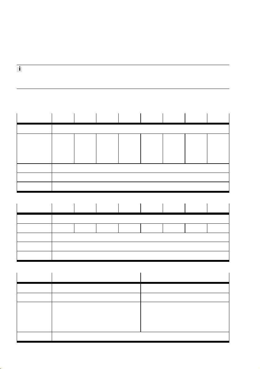
Bit 47 46 45 44 43 42 41 40
Process data "StatusWord"
Data content "Error" "Direc-
tionCloseFlag"
Value range 0…65535
Index 0x0028
Data type UIntegerT16
Tab. 13 Process data IN
"DirectionOpenFlag"
"LatchDataOk"
"UndefinedPositionFlag"
"ClosedPositionFlag"
"GrippedPositionFlag"
"OpenedPositionFlag"
Bit 39 38 37 36 35 34 33 32
Process data "StatusWord"
Data content
–
"Ready"
– – – – – –
Value range 0…65535
Index 0x0028
Data type UIntegerT16
Tab. 14 Process data IN
Bit 31 …16 15 …0
Meaning MSB…LSB MSB…LSB
Process data "ErrorNumber" "ActualPosition"
Value range 0…65535 0…max. jaw stroke
– EHPS-16: 0…2150
– EHPS-20: 0…2750
– EHPS-25: 0…3350
Index 0x0028
18 Festo — EHPS-...-LK — 2019-08
Page 19
IO-Link Interface description
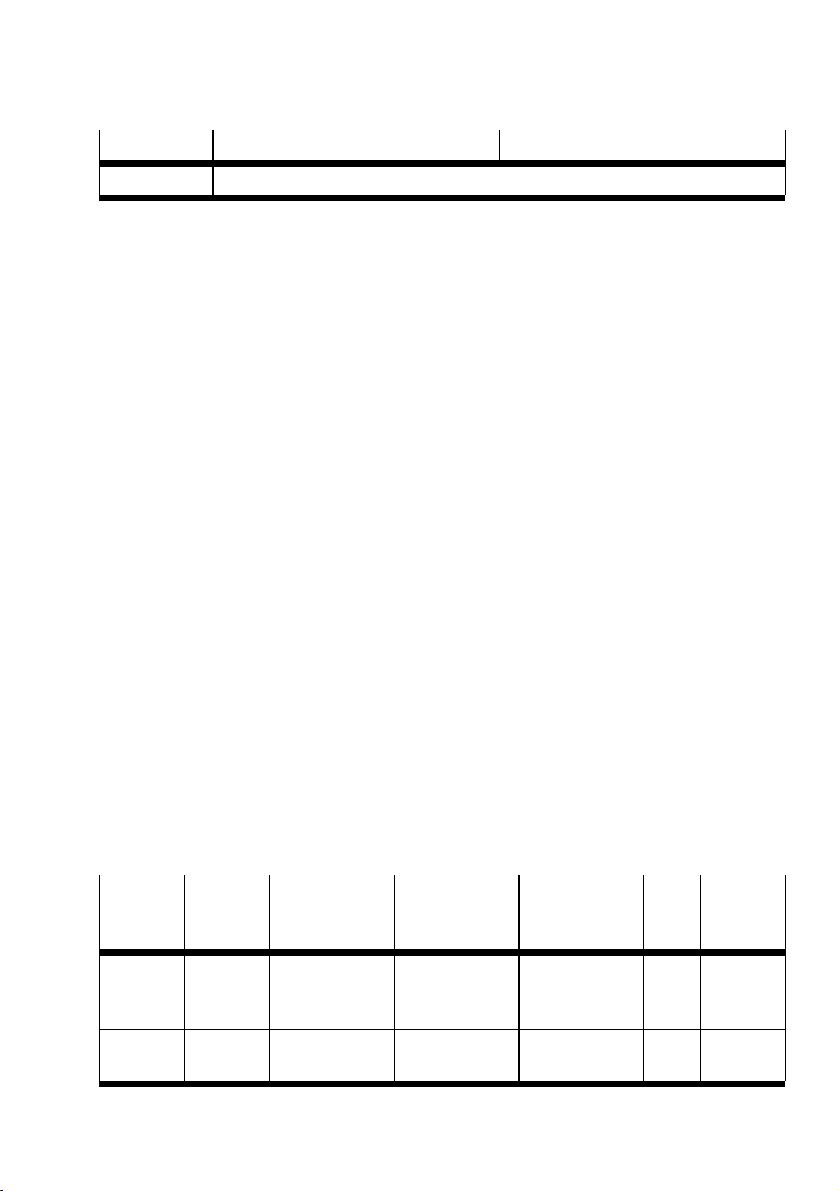
Bit 31 …16 15 …0
Data type UIntegerT16
Tab. 15 Process data IN
9.7.1 Description "StatusWord"
"Ready" (bit 38)
Active as soon as the gripper is raised. It can also be used to check a byte swap.
"OpenedPositionFlag" (bit 40)
Active when the open position is reached. In the case of a previous redefinition of the end position,
the bit always becomes active when the gripper has reached this stored position or is further opened.
"GrippedPositionFlag" (bit 41)
Active, if the gripper is in the taught-in or predefined gripper position, taking into account the predefined tolerances.
"ClosedPositionFlag" (bit 42)
Active when the gripper has reached the closed position. In the case of a previous redefinition of the
end position, the bit always becomes active when the gripper has reached this stored position or is
further closed.
"UndefinedPositionFlag" (bit 43)
Active if the gripper is in an undefined position.
"LatchDataOk" (bit 44)
Active as soon as the transmitted data has been transferred from the gripper.
"DirectionOpenFlag" (bit 45)
This bit is a direction flag and becomes active if the last run command was from the "Open" master.
"DirectionCloseFlag" (bit 46)
This bit is a direction flag and becomes active if the last run command was from the "Close" master.
"Error" (bit 47)
Active if there is an error. The present errors can be viewed in the "ErrorNumber" and "ErrorMessage"
parameters.
9.8 Device-specific parameters
Index Sub index Name Description Value (example) Lengt-
h
[byte]
0x0018 "Application-
SpecificTag"
0x0040 "StatusWord"
Text to be
defined by the
user
1)
è 9.7 Process
Data IN
*** 32 StringT
Format
19Festo — EHPS-...-LK — 2019-08
Page 20

IO-Link Interface description
Index Sub index Name Description Value (example) Lengt-
h
[byte]
0x0041 "ErrorNumber"
1)
è 9.7 Process
Data IN
0x0042 "CycleCounter" Counter for grip-
0…429496729-54 UIntegerT
ping cycles
0x0043 "Temperature" Gripper temper-
0…65535 2 UIntegerT
ature in °C
If the gripper
<temperature is
0 °C, 0 is output.
0x0044 "ControlWord"
1)
è 9.6 Process
Data OUT
0x0045 "ErrorMessage" Outputs an error
64 StringT
description.
0x0046 "ErrorCount" Counter of error
2 UIntegerT
messages
è 9.12 Fault
clearance IOLink
0x0100 "ActualPosition
1)
"
0x0101 "GrippingPosi-
2)
tion"
è 9.7 Process
Data IN
Gripper position
e.g. for checking
the workpiece
dimensions
0…nominal
stroke
(+tolerance)
– EHPS-16:
2 UIntegerT
0…2150
– EHPS-20:
0…2750
– EHPS-25:
0…3350
0x0102 "WorkpieceNo"1)Workpiece num-
0…32 1 UIntegerT
ber of a workpiece set
0x0103 "GrippingMode"2)Driving mode – Invalid: 0
1 UIntegerT
– Universal:
100
Format
32
16
16
16
8
8
20 Festo — EHPS-...-LK — 2019-08
Page 21

IO-Link Interface description
Index Sub index Name Description Value (example) Lengt-
h
[byte]
– External
gripping: 60
– Internal
gripping: 70
0x0104 "GrippingToler-
2)
ance"
Tolerance of
"GrippingPosi-
0…255 1 UIntegerT
tion"
0x0105 "GrippingForce"2)– Invalid
– Gripping
force level
1: approx.
50%
– Gripping
– 0
– 1
– 2
– 3
– 4
1 UIntegerT
force level
2: approx.
70%
– Gripping
force level
3: approx.
85%
– Gripping
force level
4: 100%
0x0800 0x081F
"WorkpieceSet" Workpiece sets
with 4 paramet-
5 RecordT40
ers each
1 "GrippingMode" Description see
Index: 0x0103
2 "GrippingForce" Description see
Index: 0x0105
3 "GrippingPosi-
4 "GrippingToler-
1) Copy of the process data
2) Currently used data
tion"
ance"
Description see
Index: 0x0101
Description see
Index: 0x0104
Tab. 16 Device-specific parameters
Format
8
8
21Festo — EHPS-...-LK — 2019-08
Page 22
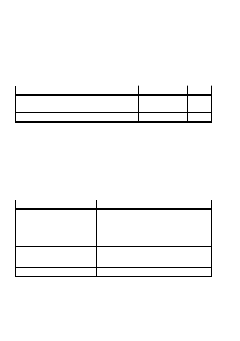
IO-Link Interface description
Parameters "GrippingPosition"
The gripping position is the value that can either be entered manually in the workpiece or described
using the "TeachGrippingPosition" command. As soon as the position is reached within the "GrippingTolerance", it is returned in the "GrippedPositionFlag" with "StatusWord".
Since the different sizes have different strokes, the permissible values for the parameter depend on
the size. The value range goes from 0 to the total stroke of the gripper in [mm x 100]. The value "0" is
the open state and the maximum value is the closed state.
EHPS-...-A-LK 16 20 25
permissible value range total stroke [mm x 100] 0…2150 0…2750 0…3350
Values in open state [mm x 100] 0 0 0
Theoretical values in the closed state [mm x 100] 2000 2600 3200
Tab. 17 "GrippingPosition" parameter
Parameters "WorkpieceNo"
The number to select a workpiece set.
– 0: Current process data are used.
– 1-32: Data from the corresponding "WorkpieceSet"one are used.
Parameters "GrippingMode"
A movement mode can be set with this parameter.
3 modes are possible:
– Universal operation: "universal"
– External gripping: "external gripping"
– Internal gripping: "internal gripping"
Gripping mode Decimal value Description
"universal" 100 Opening and closing movements are carried out with the
force ("GrippingForce") set and thus at the same speed.
"internal gripping" 70 The opening movement takes place with the force set in
"GrippingForce" and the (resulting) speed. The closing
movement takes place at maximum speed.
"external
gripping"
60 The closing movement takes place with the force specified
in "GrippingForce" and the (resulting) speed. The opening
movement takes place at maximum speed.
"Invalid" 0
–
Tab. 18 Gripping modes
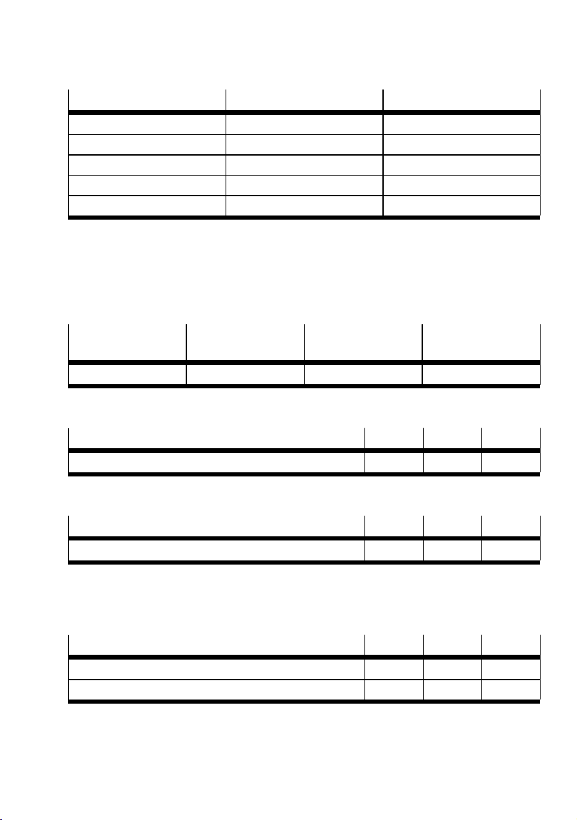
Parameters "GrippingForce"
The gripping force can be adjusted in 4 different force levels. Since the gripping force is built up
dynamically via the speed, a change in the gripping force setting also results in a change in speed.
22 Festo — EHPS-...-LK — 2019-08
Page 23
IO-Link Interface description
Power stage Decimal value Force value
Invalid 0
–
Level 1 1 approx. 50%
Level 2 2 approx. 70%
Level 3 3 approx. 85%
Level 4 4 approx. 100%
Tab. 19 "GrippingForce" parameter
Parameters "GrippingTolerance"
With this parameter, a tolerance can be set for the gripper exclusively for the "GrippingPosition" parameter. This functionality is helpful, for example, when checking the correct workpiece.
The entered value is effective in both directions of the "GrippingPosition". The total tolerance field
width is therefore twice the tolerance value.
Parameter Decimal value Resolution Tolerance to be recor-
ded
"GrippingTolerance" 0…255 0.01mm 0…±2.55 mm
Tab. 20 GrippingTolerance" parameter
The following repeat accuracy can be achieved:
EHPS-...-A-LK 16 20 25
Repetition accuracy [mm] ± 0.02 ± 0.02 ± 0.02
Tab. 21 Repetition accuracy
The linearity of the displacement measuring system over the entire stroke is enclosed:
EHPS-...-A-LK 16 20 25
Linearity [mm] ± 0.05 ± 0.1 ± 0.15
Tab. 22 Linearity
In the case of a gripper exchange, the taught-in and stored in IO-Link Data Storage positions of the
workpieces can be returned by the displacement encoder with the following accuracy (plus tolerance
of the gripper fingers):
EHPS-...-A-LK 16 20 25
External gripping interchangeability [mm] ± 0.1 ± 0.1 ± 0.2
Internal gripping interchangeability [mm] ± 0.5 ± 0.5 ± 0.7
Tab. 23 Interchangeability
Parameters "WorkpieceSet"
In the gripper, 4 parameters can be defined for each of 32 different workpieces
23Festo — EHPS-...-LK — 2019-08
Page 24

IO-Link Interface description
– "GrippingMode"
– "GrippingForce"
– "GrippingPosition"
– "GrippingTolerance"
The writing of the "WorkpieceSet" is exclusively via the process data with the "LatchData" and
"Store"commands. No value must be specified for the "GrippingPosition" parameter; this parameter
can also be taught-in with "TeachGrippingPosition".
9.9 Commissioning
Byte-Swap
Correct data mapping is can be recognised by the "Ready" bit, since this is the only one set after
switching on.
9.10 Datastorage
The following data can be transferred in the Datastorage:
– "ApplicationSpecificTag"
– Data from the "WorkpieceSet":
– "GrippingMode"
– "GrippingForce"
– "GrippingPosition"
– "GrippingTolerance"
9.11 System Commands
The gripper can be operated without prior input of valid process data via the System Commands 160,
161 and 162.
The following parameters are stored via the System Commands for operation:
– "GrippingForce":1
– "GrippingMode":Universal
Name Description Index Value
[Restore Factory Settings] Reset of all parameters to the fact-
ory values
[Enable Gripper] Activation of system commands for
easy triggering of movement commands. A standard configuration is
thus loaded into the parameters and
the movement commands are
released.
[Close Gripper] With previous release, this com-
mand can initiate a movement of the
gripper jaws in the direction of
"closing".
24 Festo — EHPS-...-LK — 2019-08
0x0002 130
0x0002 160
0x0002 161
Page 25

IO-Link Interface description
Name Description Index Value
[Open Gripper] With previous release, this com-
mand can initiate a movement of the
gripper jaws in the direction of
"opening".
Tab. 24 System Commands
9.12 Fault clearance IO-Link
Parameters "ErrorNumber"
Diagnostic
message
Hex (Dec)
0x0 (0) "Status ok,
0x100
(256)
0x101
(257)
0x102
(258)
0x010A
(266)
Device status Error Possible cause Remedy "Error-
device is ready"
Outside the specification
"Power supply
error"
– Actuator
supply not
connected
– Cable break
– Actuator
supply not
sufficient
Out of specification (drive can no
longer be moved)
"Temperature
too high"
– Ambient
temperature
too high
– Gripper has
overload
Out of specification (drive can no
"Temperature
too low"
Ambient temperature too low
longer be moved)
2)
Outside the specification
"Actuator under
voltage during
movement"
– Actuator
supply
unstable
– Line resist-
ance
increased
(faulty sup-
ply cable)
0x0002 162
Testing the actuator supply
voltage
ensure adequate
pressurisation/cooling/connection
ensure sufficient
operating temperature
– Check grip-
ping force,
check power
supply and
peak load
Count"
No
Yes
Yes
Yes
No
1)
25Festo — EHPS-...-LK — 2019-08
Page 26

IO-Link Interface description
Diagnostic
message
Hex (Dec)
0x300
(768)
0x301
(769)
0x302
(770)
0x304
(772)
0x305
(773)
0x306
(774)
0x307
(775)
0x308
(776)
Device status Error Possible cause Remedy "Error-
Count"
– Power sup-
ply not sufficiently
designed for
peak loads,
faulty supply
– Manual
acknowledgement of
error message necessary
cables
Outside the specification
"ControlWord
not plausible"
Wrong value in
"ControlWord"
Checking the
value in the
No
"ControlWord"
Outside the specification
Outside the specification
Outside the specification
Failure "Reference posi-
"GrippingPosition not
plausible"
"GrippingForce
not plausible"
"GrippingTolerance not plausible"
tion error"
Incorrect value in
parameter "GrippingPosition"
Incorrect value in
parameter "GrippingForce"
Incorrect value in
parameter "GrippingTolerance"
Gripper has no
reference posi-
Check the parameter "GrippingPosition"
Check the parameter "GrippingForce"
Check the parameter "GrippingTolerance"
Service Festo AG
& Co. KG
No
No
No
Yes
tion
Outside the specification
Motion task cannot be executed
"GrippingMode
not plausible"
"Drive command
cannot be
executed"
Incorrect value in
parameter "GrippingMode"
Multiple travel
commands in the
same direction
Check the parameter "GrippingMode"
Reset "ResetDirectionFlag" direction flag or
No
No
send movement
command in the
other direction
Outside the specification
"WorkpieceNo
not plausible"
Incorrect value in
parameter
"WorkpieceNo"
Check the parameter "WorkpieceNo"
No
1)
26 Festo — EHPS-...-LK — 2019-08
Page 27

IO-Link Interface description
Diagnostic
message
Hex (Dec)
0x309
(777)
0x30D
(781)
0x30F
(783)
0x310
(784)
0x311
(785)
0x312
(786)
0x400
2)
(1024)
Device status Error Possible cause Remedy "Error-
Count"
Outside the specification
Outside the specification
Outside the specification
Outside the specification
Outside the specification
Outside the specification
"GrippingPosition not latched"
"GrippingForce
not latched"
"GrippingTolerance not
latched"
"GrippingMode
not latched"
"WorkpieceNo
not latched"
"Initial handshake missing"
Process data
sent by the master have been
changed
Process data
sent by the master have been
changed
Process data
sent by the master have been
changed
Process data
sent by the master have been
changed
Process data
sent by the master have been
changed
After a cold start,
a single data
migration by
"Latch-
Transfer of the
changed parameters by
"LatchData."
Transfer of the
changed parameters by
"LatchData."
Transfer of the
changed parameters by
"LatchData."
Transfer of the
changed parameters by
"LatchData."
Transfer of the
changed parameters by
"LatchData."
Transfer of the
changed parameters by
"LatchData."
No
No
No
No
No
No
Data"("ControlWord" = 1) is
required.
Failure "Gripper
blocked"
– Gripper is
difficult to
move
– The travel
path of the
grab is
– Restoring
the free
movement of
the gripper
– Service Festo
AG & Co. KG
Yes
impaired
1)
27Festo — EHPS-...-LK — 2019-08
Page 28
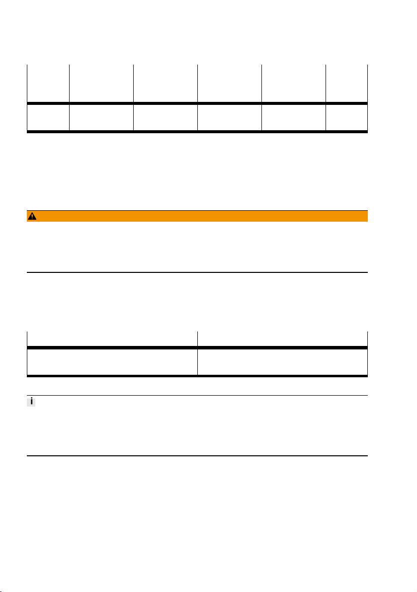
Maintenance
Diagnostic
message
Hex (Dec)
0x406
(1030)
1) Incrementing the "ErrorCount" parameter for these messages
2) Acknowledge error with "ResetError"
Tab. 25 "ErrorNumber" parameter
Device status Error Possible cause Remedy "Error-
Count"
Failure "System error /
internal error"
Internal system
error
Service Festo AG
& Co. KG
Yes
10 Maintenance
10.1 Safety
WARNING!
Danger of crushing due to unexpectedly fast-moving loads and unintentional movements.
• Remove the payload.
• Switch off power to the product.
• Safeguard the power supply from being switched on again unintentionally.
10.2 Cleaning
• Clean the outside of the product with a soft cloth. Do not use aggressive cleaning agents.
10.3 Lubrication
Interval Maintenance work
After 5 million switching cycles Grease the guide of the gripper jaws. Permissible
lubricating grease èwww.festo.com/spareparts.
Tab. 26
1)
Cut the lubrication interval by half if one of the following applies:
• High thermal stress
• Heavy contamination
• Proximity of grease-dissolving liquids or vapours
11 Malfunctions
11.1 Diagnostics
28 Festo — EHPS-...-LK — 2019-08
Page 29
Malfunctions
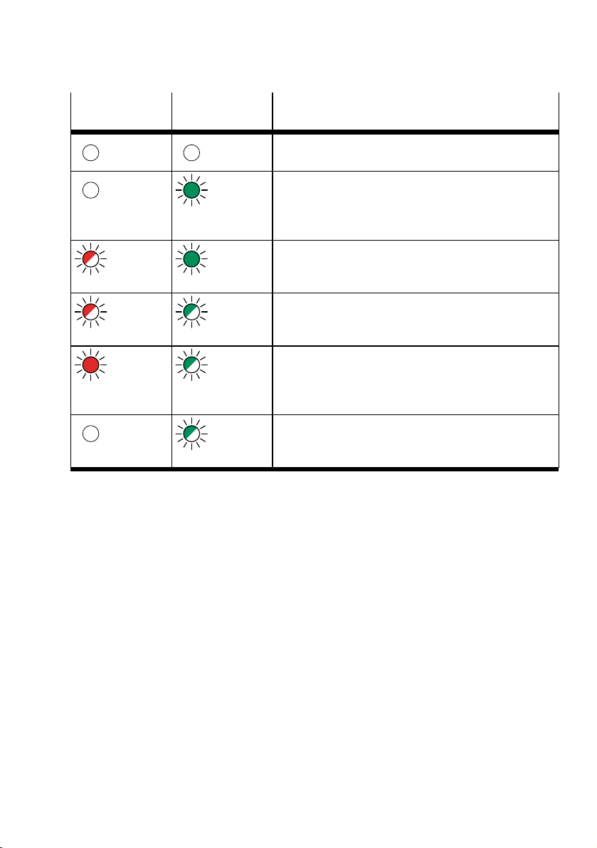
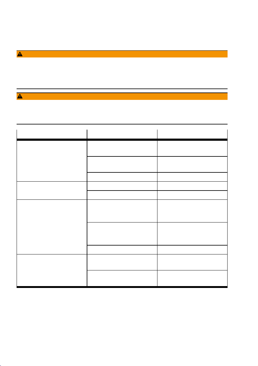
LED red "Error" LED green
"Ready"
Off Off – IO-Link Supply voltage is not connected èIO-Link-
Off Illumin-
Flashes
red
Flashes
red
red on Flashes
Off Flashes
Tab. 27 LED display
ated green
Illuminated green
Flashes
green
green
green
Meaning
Communication not active.
Actuator ready for operation (Fallback, SIO Mode)
– IO-Link Supply voltage: connected
– IO-Link Communication: not active
– Actuator supply voltage: connected
– IO-Link Supply voltage: connected
– IO-Link Communication: not active
– Actuator supply voltage: not connected
– IO-Link Supply voltage: connected
– IO-Link Communication: active
– Actuator supply voltage: not connected
– IO-Link Supply voltage: connected
– IO-Link Communication: active
– Actuator supply voltage: connected
– "ErrorNumber" and "ErrorCode" is output
– IO-Link Supply voltage: connected
– IO-Link Communication: active
– Actuator supply voltage: connected
29Festo — EHPS-...-LK — 2019-08
Page 30
Malfunctions
11.2 Fault clearance
WARNING!
Danger of crushing due to unexpectedly fast-moving loads and unintentional movements.
• Remove the payload.
• Switch off power to the product.
• Safeguard the power supply from being switched on again unintentionally.
WARNING!
Danger of crushing.
The gripper fingers could move unintentionally and crush body parts.
• Do not reach into the movement range.
Fault description Cause Remedy
Gripper does not hold payload
firmly.
formly.
Gripper fingers do not
open/close.
Squeaking noises
Tab. 28
Gripping point of gripper fingers
Move gripping point inwards.
is too far outwards.
Sufficient force cannot be
applied.
Increase travel path. Minimum
travelè 14 Technical data.
Payload is too heavy. Select a larger gripper.
Slots are dirty. Clean and grease the slots.Gripper fingers do not move uni-
Gripper jaws are distorted. Rectify distortion.
Jamming due to excessive
speed of the gripper fingers
Resolve jamming
è Resolve mechanical jamming
of gripper jaws.
Interruption of communication
between gripper and control
Check connecting cable.
IO-Link Check master.
unit
Gripper is faulty. Replace gripper.
Lack of lubrication Lubricate gripper
è 10.3 Lubrication.
Payload is too great. Observe permissible values
è 14 Technical data.
30 Festo — EHPS-...-LK — 2019-08
Page 31
Disassembly
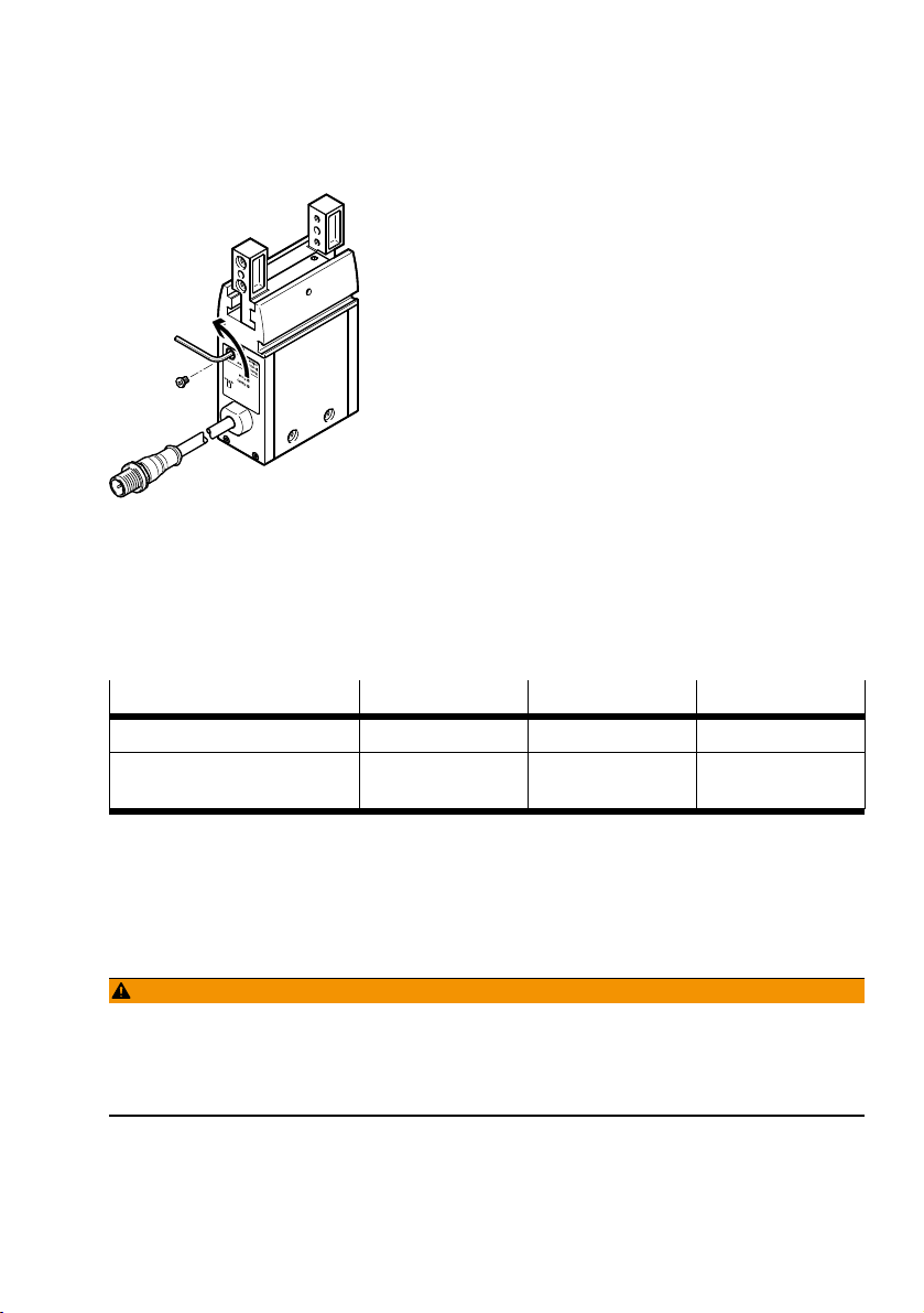
Resolve mechanical jamming of gripper jaws
Fig. 7 Resolve jamming of gripper jaws
1. Remove the plug screw.
2. Rotate the worm shaft underneath using the hex wrench until the jamming is resolved:
– Anti-clockwise (external gripping)
– Clockwise (internal gripping)
3. Retighten plug screw.
Size 16 20 25
Hex wrench ß 1.5 ß 1.5 ß 2
Tightening torque for
plug screw
Tab. 29 Tightening torques
[Nm] 0.6 0.6 2.8
11.3 Repair
Send product to the Festo repair service for repair.
12 Disassembly
WARNING!
Danger of crushing due to unexpectedly fast-moving loads and unintentional movements.
• Remove the payload.
• Switch off power to the product.
• Safeguard the power supply from being switched on again unintentionally.
31Festo — EHPS-...-LK — 2019-08
Page 32
Disposal
13 Disposal
Dispose of the product and packaging at the end of its useful life through environmentally friendly
recycling in accordance with applicable regulations.
14 Technical data
14.1 Technical data, general
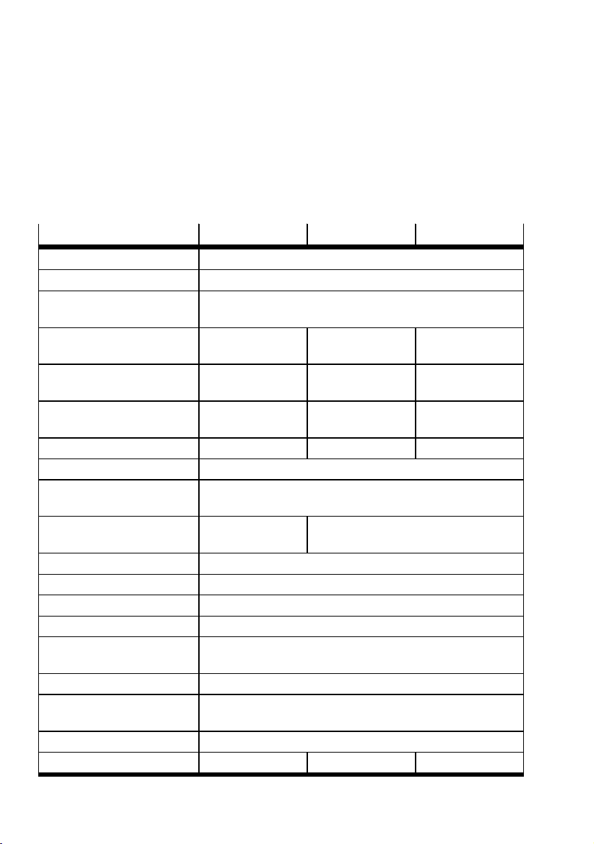
Size 16 20 25
Constructive design Electric parallel gripper
Mounting position Any
Minimum travel per jaw
for max. gripping force
Mass moment of inertia [kg
Max. load per gripper
finger
Max. permissible
length of gripper finger
Repetition accuracy [mm] £0.03 £0.01 £0.01
Max. interchangeability [mm] £0.02
Nominal operating
voltageDC
Max. current consumption
Max. cable length [m] 20 (including gripper cable)
Min. wire cross section [mm2]0.34
Degree of protection IP40
Relative humidity [%] 0…95 (at 25C non-condensing)
Ambient
temperature
Storage temperature [°C] –20…+60
CE marking (declaration of conformity)
Electrical safety In accordance with standard EN 61010-1:2010
Weight [g] 296 532 904
1)
[mm] 0.5
0.78 2.02 5.24
cm²]
[g] 100 150 230
[mm] 80 100 120
[VDC] Sensor IO-Link: 18…30
Actuator: 24±10%
[A] 1 2
[°C] +5…+60
As per EU EMC Directive2)
3)
32 Festo — EHPS-...-LK — 2019-08
Page 33
Technical data
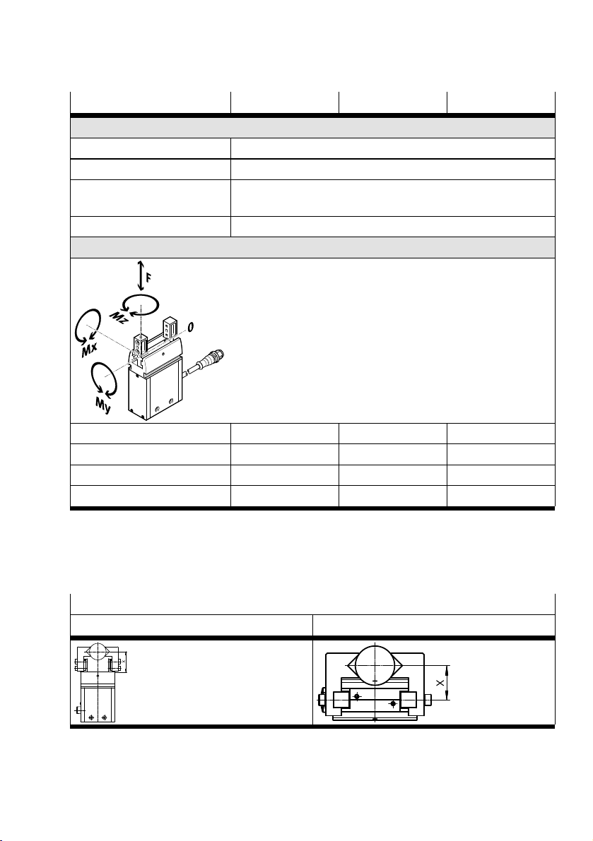
Size 16 20 25
Materials
Housing Aluminium
Cover Polymer
Gripper jaws, bearings,
Steel
plugs, screws
O-ring NBR
Max. force (static) and max. torque (static)
F
Z
M
X
M
Y
M
Z
1) Max. housing temperature = ambient temperature +35K
2) Only when using the connecting cable from Festo
3) Max. length of connecting cable (including gripper cable): 20m
[N] 200 325 450
[Nm] 7 13 28
[Nm] 4.4 8 16
[Nm] 7 13 28
Tab. 30 Technical data
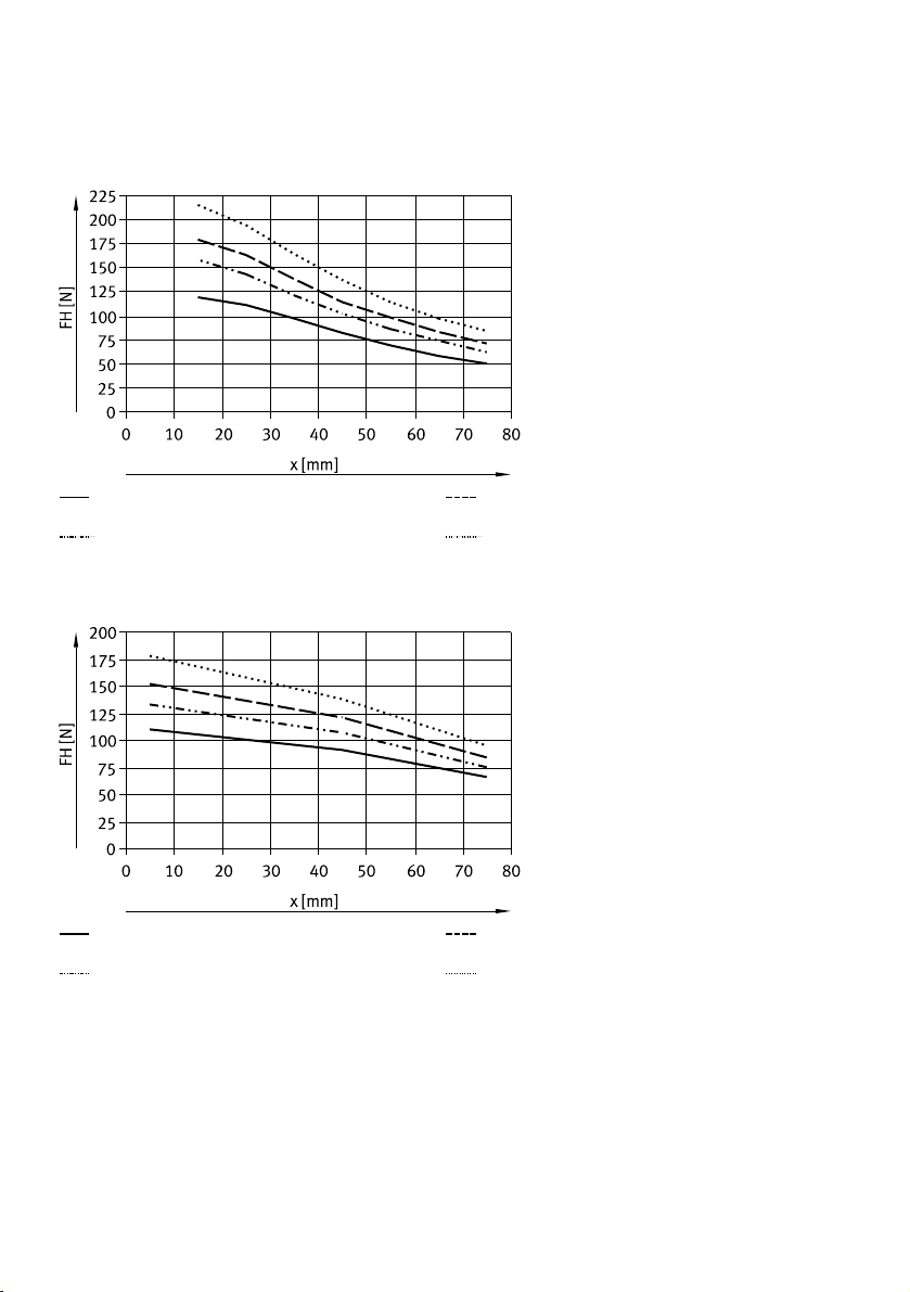
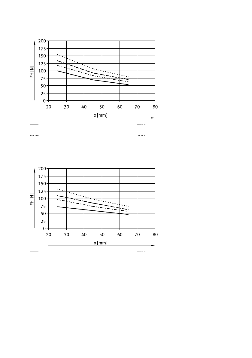
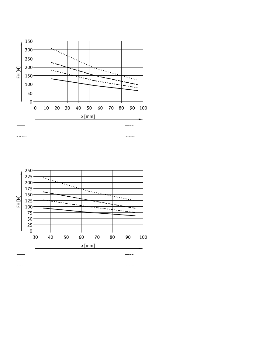
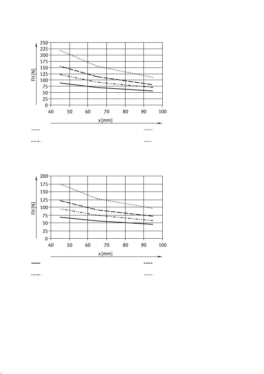
14.2 Characteristic curves
Lever arm x
Vertical Horizontal
Tab. 31 Alignment of lever arm x
33Festo — EHPS-...-LK — 2019-08
Page 34
Technical data
Total gripping force FH (2x jaw gripping force) as a function of lever arm x and force class
Power class 1
Power class 2
Fig. 8 EHPS-16 external gripping, lever arm vertical
Power class 1
Power class 2
Fig. 9 EHPS-16 internal gripping, lever arm vertical
Power class 3
Power class 4
Power class 3
Power class 4
34 Festo — EHPS-...-LK — 2019-08
Page 35
Technical data
Power class 1
Power class 2
Fig. 10 EHPS-16 external gripping, lever arm horizontal
Power class 1
Power class 2
Fig. 11 EHPS-16 internal gripping, lever arm horizontal
Power class 3
Power class 4
Power class 3
Power class 4
35Festo — EHPS-...-LK — 2019-08
Page 36
Technical data
Power class 1
Power class 2
Fig. 12 EHPS-20 external gripping, lever arm vertical
Power class 1
Power class 2
Fig. 13 EHPS-20 internal gripping, lever arm vertical
Power class 3
Power class 4
Power class 3
Power class 4
36 Festo — EHPS-...-LK — 2019-08
Page 37
Technical data
Power class 1
Power class 2
Fig. 14 EHPS-20 external gripping, lever arm horizontal
Power class 1
Power class 2
Fig. 15 EHPS-20 internal gripping, lever arm horizontal
Power class 3
Power class 4
Power class 3
Power class 4
37Festo — EHPS-...-LK — 2019-08
Page 38
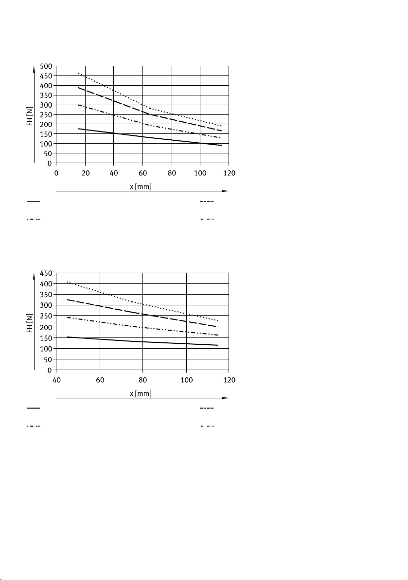
Technical data
Power class 1
Power class 2
Fig. 16 EHPS-25 external gripping, lever arm vertical
Power class 1
Power class 2
Fig. 17 EHPS-25 internal gripping, lever arm vertical
Power class 3
Power class 4
Power class 3
Power class 4
38 Festo — EHPS-...-LK — 2019-08
Page 39
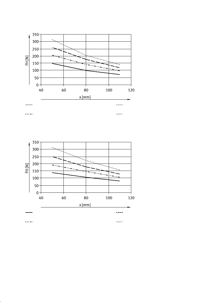
Technical data
Power class 1
Power class 2
Fig. 18 EHPS-25 external gripping, lever arm horizontal
Power class 1
Power class 2
Fig. 19 EHPS-25 internal gripping, lever arm horizontal
Power class 3
Power class 4
Power class 3
Power class 4
39Festo — EHPS-...-LK — 2019-08
Page 40

Reproduction, distribution or sale of this document or communication of its contents to others without express authorization is
prohibited. Offenders will be liable for damages. All rights
reserved in the event that a patent, utility model or design patent
is registered.
Copyright:
Festo AG & Co. KG
Ruiter Straße 82
73734 Esslingen
Germany
Phone:
+49 711 347-0
Internet:
www.festo.com
 Loading...