

Page 1

EGSC-BS-KF
Mini slide
Instructions | Operating
8099637
8099637
2018-11c
[8099639]
Page 2

Translation of the original instructions
2 Festo — EGSC-BS-KF — 2018-11c
Page 3

Table of contents
1 About this document................................................................................................... 4
2 Safety........................................................................................................................... 4
2.1 Safety instructions........................................................................................................ 4
2.2 Intended use................................................................................................................ 4
2.3 Training of qualified personnel..................................................................................... 4
3 Additional information................................................................................................ 4
4 Service..........................................................................................................................4
5 Product overview......................................................................................................... 5
5.1 Function....................................................................................................................... 5
5.2 Design........................................................................................................................... 5
6 Transport..................................................................................................................... 6
7 Assembly..................................................................................................................... 7
7.1 Preparation................................................................................................................... 7
7.2 Mounting...................................................................................................................... 8
7.3 Attachment................................................................................................................... 9
7.4 Mounting accessories................................................................................................... 10
8 Commissioning............................................................................................................ 12
9 Service..........................................................................................................................13
10 Disassembly................................................................................................................ 14
11 Disposal........................................................................................................................14
12 Fault clearance............................................................................................................ 15
13 Technical data............................................................................................................. 16
3Festo — EGSC-BS-KF — 2018-11c
Page 4
About this document
1 About this document
All available documents for the product èwww.festo.com/pk.
The mini slideEGSC-BS-KF is designated as product in these operating instructions. Read the operating instructions carefully before starting all work on the product.
2 Safety
2.1 Safety instructions
– Observe product labelling.
– Before working on the product, switch off the power supply and secure it against being switched
back on.
– Store the product in a cool, dry environment that is protected against UV and corrosion. Ensure
short storage times.
– Protect the product during operation from damaging influences.
Damaging influences include grinding dust, glowing chips or sparks.
– Observe tightening torques. Unless otherwise specified, the tolerance is ±20%.
2.2 Intended use
The mini slide is intended to be used for positioning payloads in combination with tools.
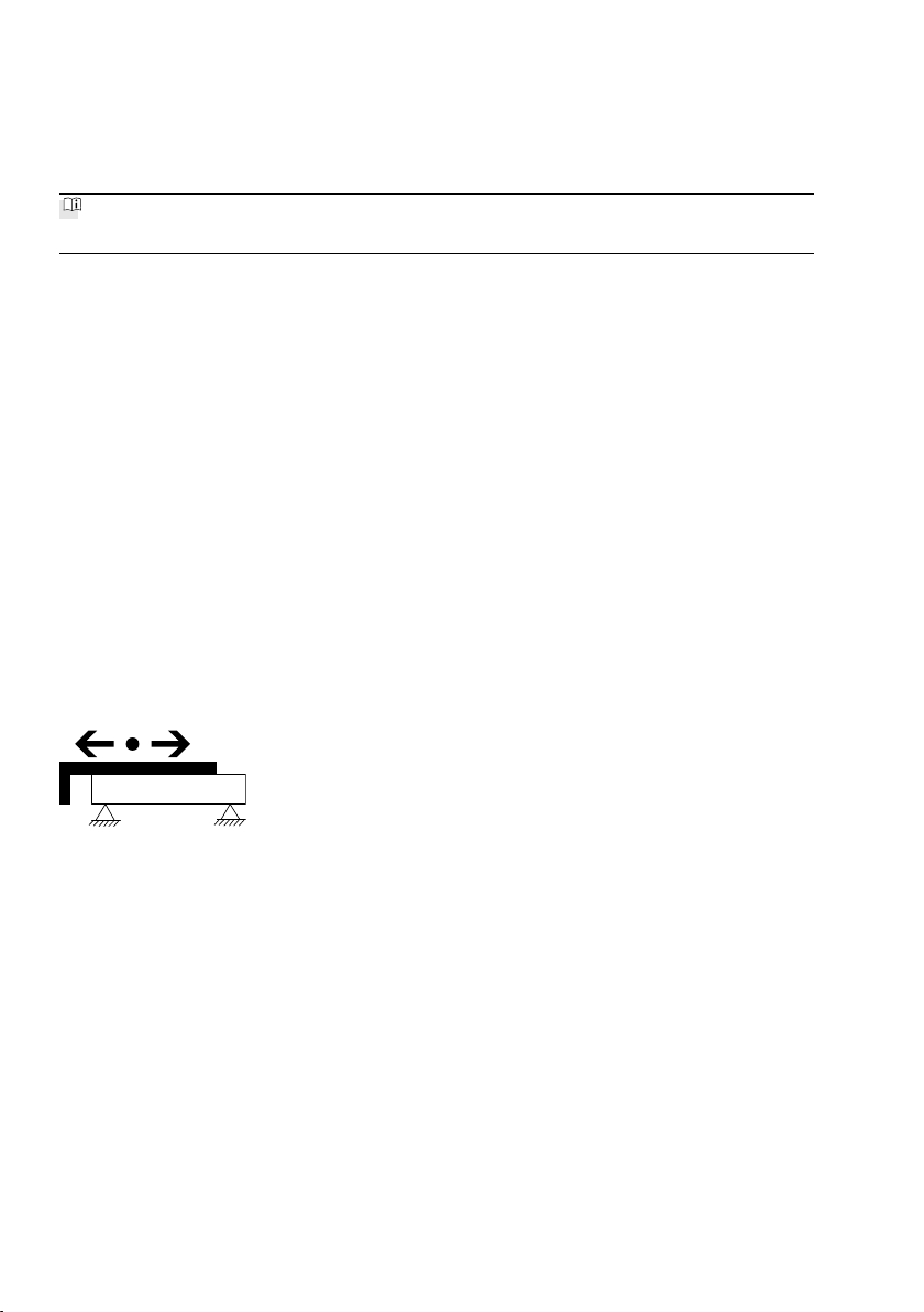
The mini slide is approved for the "Slide Operation" mode è Fig.1.
Fig. 1
2.3 Training of qualified personnel
Only skilled personnel may carry out installation, commissioning, maintenance and disassembly of the
product. The qualified personnel must be familiar with installation of electrical control systems.
3 Additional information
Accessories è www.festo.com/catalogue
4 Service
Contact your regional Festo contact person if you have technical questions
è www.festo.com
Festo — EGSC-BS-KF — 2018-11c4
Page 5
Product overview
5 Product overview
5.1 Function
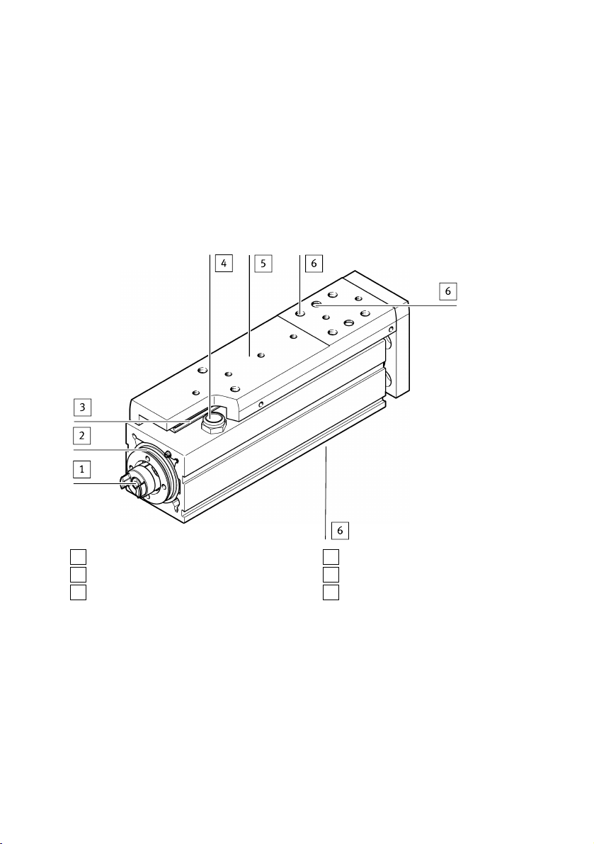
A rotating ball screw drive converts the rotation of a motor into straight-line motion. As a result, the
slide 5 moves backwards and forwards. The slide is ball-bearing guided. The reference position of the
slide can be determined using proximity sensors (è 7.4 Mounting accessories) or by referencing a
fixed stop (retracted end position).
5.2 Design
1
Drive hub
2
Interface for motor mounting kit
3
Guide rail
Fig. 2
4
Venting hole with filter element
5
Slide with ball guide
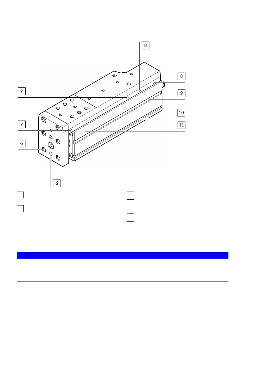
6
Thread/centring holes for attachment components
5Festo — EGSC-BS-KF — 2018-11c
Page 6
Transport
6
Thread/centring holes for attachment components
7
Drilled hole for accessories, at both ends
(e.g. clamping unit)
Fig. 3
8
Thread for optional switch lug
9
Slot for sensor bracket
10
Slots for attachment
11
Profile housing
6 Transport
NOTICE!
Unexpected movement of components. The mini slide is unbraked. Without input torque, the slide is
freely movable.
• Secure slide during transport.
• Take product weight into account è 13 Technical data.
6 Festo — EGSC-BS-KF — 2018-11c
Page 7
Assembly
7 Assembly
7.1 Preparation
– Do not modify the screws and threaded pins.
Exception: if immediate modification is required based on these operating instructions.
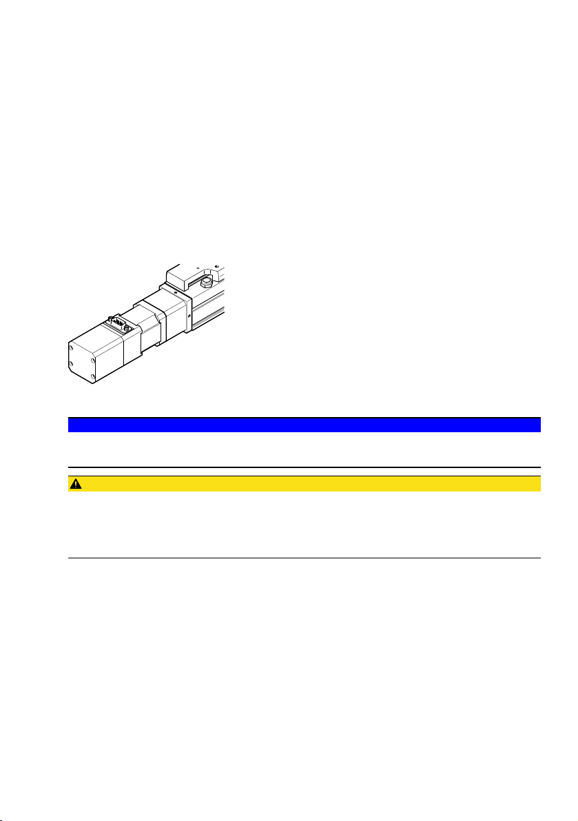
– Select the motor and motor mounting kit from the Festo catalogue èwww.festo.com/catalogue
When using other motors: observe the critical limits for forces, torques and speeds
è 13 Technical data.
– When mounting the motor: follow the assembly instructions for the motor mounting kit.
– Connect motor cables only after the mini slide is mounted.
Fig. 4
NOTICE!
The reference position is lost when the motor is dismounted (e.g., when turning the motor around).
• Start homing è 8 Commissioning.
CAUTION!
With vertical or diagonal mounting position:
When power is off, the slide can travel or fall uncontrolled into the lower end position. Injury due to
impacts or crushing.
• Bring moving parts of the product into a safe end position or secure them against falling.
– Place the product in such a way that the operating elements can be reached.
– Install product without tension or distortion.
– Fasten product to a mounting surface with flatness of 0.05% of the stroke length, but max.
0.5mm.
For gantry applications, attention must also be paid to parallel alignment or product height when
aligning the axes.
For additional information, contact your local Festo Service.
7Festo — EGSC-BS-KF — 2018-11c
Page 8
Assembly
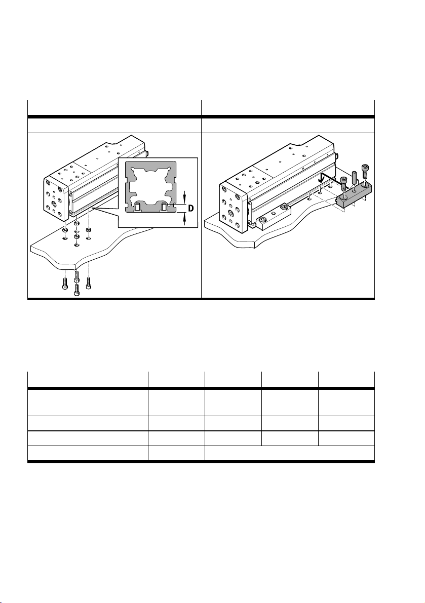
7.2 Mounting
Interfaces for mounting components
On the housing On the profile
With screws For example, with profile mounting EAHF-L2
1) Accessoriesèwww.festo.com/catalogue
Tab. 1 Mounting alternatives
1. Select mounting components according to the hole pattern èwww.festo.com/catalogue
2. Mount the mounting components outside the positioning range to avoid collisions.
3. Mount the mini slide.
4. Tighten screws evenly.
1)
Size 25 32 45 60
Screw
M3 M4 M5 M5
(on housing)
Max. screw-in depth D [mm] 6 8.5 7 8
Tightening torque [Nm] 1.4 3.4 3.2 3.2
Centring H7
1) Remove the rubber cover cap
1)
[mm] @ 5 @ 7
Tab. 2
8 Festo — EGSC-BS-KF — 2018-11c
Page 9
Assembly
7.3 Attachment
Requirements
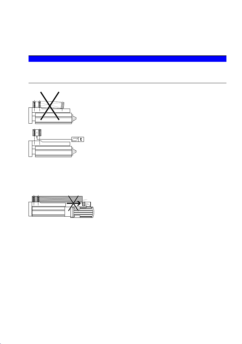
NOTICE!
A warped attachment component bends the slide and shortens the service life of the guide.
• Use an attachment component with an even surface. Evenness: t = 0.01 mm è Fig.5
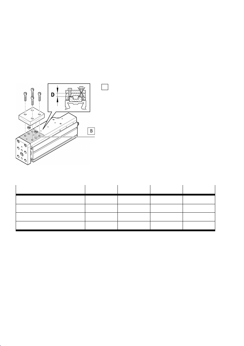
• Mount only to the mounting surface (B) è Fig.7.
Fig. 5
– Set down rated load in such a way that the tilt moment resulting from the force (parallel to the
axis of movement) and lever arm are kept as small as possible.
– Avoid collisions of the mounting part and payload with other mounting parts è Fig.6.
Fig. 6
9Festo — EGSC-BS-KF — 2018-11c
Page 10
Assembly
Mounting
– Fasten the attachment to the slide with screws and centring sleeves. Observe the maximum screw-
in depth D and tightening torque è Tab.3.
For attachment components with their own guide:
– Precisely adjust the additional guide and mini slide or use a connection that enables a tolerance
compensation. In this way, the guide is not overloaded.
B
Assembly surface
Fig. 7
Size 25 32 45 60
Screw M3 M4 M5 M5
Max. screw-in depth D [mm] 4.5 5 6 8
Tightening torque [Nm] 1.5 2.7 5.1 6.5
Centring H7 [mm] @ 2 @ 4 @ 5 @ 7
Tab. 3
7.4 Mounting accessories
To protect the end positions against uncontrolled overtravel:
– Check the necessity of proximity sensors (hardware limit switches).
If proximity sensors are used as limit switches:
– Preferably use proximity sensors with normally closed function.
This protects against excess travel beyond the end position, if the proximity sensor cable is
broken.
If proximity sensors are used as reference switches:
– Use proximity sensors that correspond to the input of the controller being used.
10 Festo — EGSC-BS-KF — 2018-11c
Page 11
Assembly
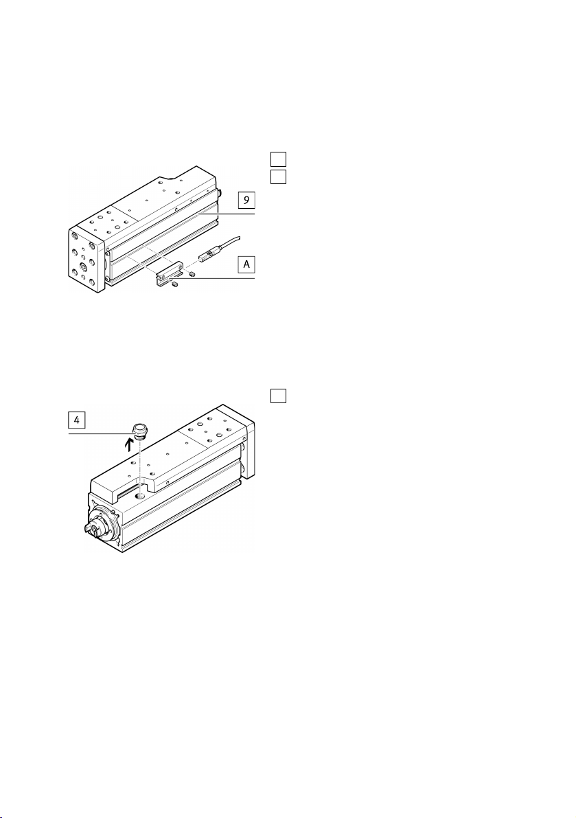
Proximity sensor mounting
Use the proximity sensor with sensor bracket [A] in the slot 9 èAssembly instructions of the
accessories.
9
Slot
A
Sensor bracket
Fig. 8
Prevention of contamination
Connect sealing air. To do so, remove the filter element 4 from the housing and connect the compressed air. Use the recommended fittings from the Festo accessories èwww.festo.com/catalogue.
4
Filter element
Fig. 9
11Festo — EGSC-BS-KF — 2018-11c
Page 12
Commissioning
8 Commissioning
CAUTION!
Risk of injury due to unexpected movement of components.
• Protect the positioning range from unwanted intervention.
• Keep foreign objects out of the positioning range.
• Perform commissioning at low speed.
NOTICE!
Incorrect set values for the braking ramp in STOP statuses
(e.g. EMERGENCY OFF, Quick Stop) result in an overloading of the spindle axis and can destroy it or
drastically reduce its service life.
• Check the settings for all braking ramps in the controller or the higher-order control system (decel-
eration values and jerk).
• Adjust delay values (braking delay, delay times) in such a way that the maximum driving torque,
acceleration or maximum feed force is not exceeded. In the process, take the following into con-
sideration:
– Travel speed
– Moving mass
– Mounting position
• When designing the spindle axis, use the Festo engineering software "PositioningDrives"
èwww.festo.com
NOTICE!
Block-shaped acceleration profiles (without jerk limitation) cause high peaks in the drive force that
can lead to an overloading of the drive. Due to overshooting effects, positions outside of the permissible range may also occur. A jerk-limited acceleration specification reduces vibrations in the entire system and has a positive effect on stress in the mechanical system.
• Check the controller settings and adapt if necessary (e.g. jerk limitation, smoothing of the acceler-
ation profile).
NOTICE!
Axes of the same design may demonstrate different running noises depending on the respective component. The following factors may also influence this issue:
• Parameterisation
• Operating mode
• Type of mounting
• Installation situation (e.g. rigidity of the foundation, vibration behaviour, resonance frequencies)
12 Festo — EGSC-BS-KF — 2018-11c
Page 13
Service
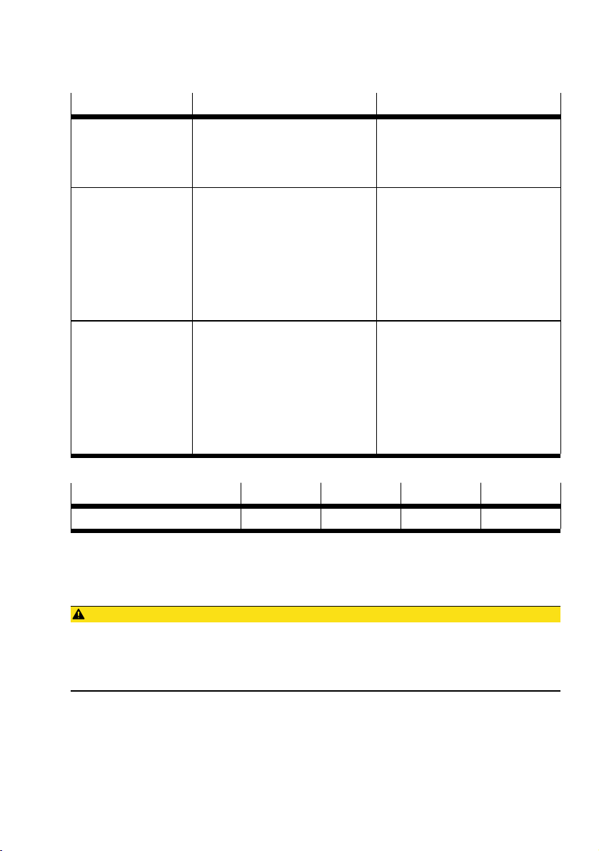
Procedure Purpose Note
1. Control travel Determining the approach direction
of the motor
Even with identical control, motors
of the same design can turn in
opposite directions due to different
wiring.
2. Homing Comparison of real situation to the
image of the controller
Homing takes place:
– Towards the reference switch
– Against an end stop. Comply
with maximum impact energy
è Tab. 5.
Observe additional information
èOperating instructions of the drive
system.
3. Test run Checking the overall behaviour Check the following requirements:
– The slide moves through the
intended positioning cycle completely.
– Slide stops as soon as a limit
switch is reached.
After a successful test run, the slide
is ready for operation.
Tab. 4
Size 25 32 45 60
Max. impact energy1)[10-3 J] 0.005 0.009 0.014 0.044
1) max. Speed of homing for all sizes: 0.01 m/s
Tab. 5
9 Service
CAUTION!
Unexpected movement of components.
Injury due to impacts or crushing.
• Before working on the product, switch off the control and secure it to prevent it from being
switched back on accidentally.
Checking wear
– Regularly check the reversing backlash of the slide for spindle nut wear. The wear on the ball
screw will lead to increased noise in the long term and eventually cause the ball screw drive to
block or the spindle nut to break. The maximum permissible reversing backlash is 0.2 mm.
13Festo — EGSC-BS-KF — 2018-11c
Page 14

Disassembly
Cleaning
– Clean the mini slide with a soft cloth if necessary. Do not use aggressive cleaning agents.
10 Disassembly
CAUTION!
Unexpected movement of components.
Injury due to impacts or crushing.
• Before working on the product, switch off the control and secure it to prevent it from being
switched back on accidentally.
• Observe transport information è 6 Transport.
– Remove motor cables and mounting components.
11 Disposal
– Dispose of the packaging and slide at the end of the production service life according to the valid
provisions for environmentally sound recycling.
14 Festo — EGSC-BS-KF — 2018-11c
Page 15
Fault clearance
12 Fault clearance
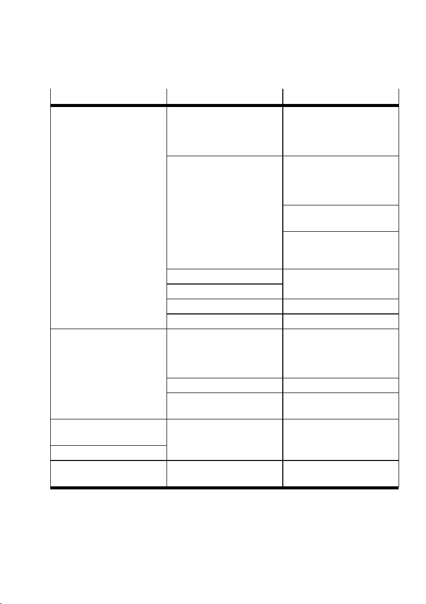
Malfunction Possible cause Remedy
Squealing noises or vibrations
Coupling spacing is wrong. Observe the permissible coupand/or the mini slide runs
roughly.
Tensions
Resonance point of the actuator
Rotational speed exceeded
Controller is set incorrectly. Change parameters.
Guide is defective or worn. Exchange the mini slide.
Slide does not move.
Coupling spins. Check the assembly of the
Loads too high. Reduce load mass/torques.
Retaining screws on tool are too
long.
The reversing backlash is too
Wear Exchange the mini slide.
large è 9 Service.
The idling torque increases.
Slide travels over end position. Proximity sensor does not
switch.
Tab. 6
ling spacings èAssembly
instructions of the motor
mounting kit.
Install the mini slide so it is free
of tension; maintain evenness
of the bearing surface
è 7.1 Preparation.
Change arrangement of the
tool/payload.
Align the mini slide precisely
parallel to the second mini
slide.
Change the travel speed.
motor mounting set
èAssembly instructions of the
motor mounting kit.
Observe the maximum screw-in
depth è 7.3 Attachment.
Check proximity sensor, connections and controller.
15Festo — EGSC-BS-KF — 2018-11c
Page 16
Technical data
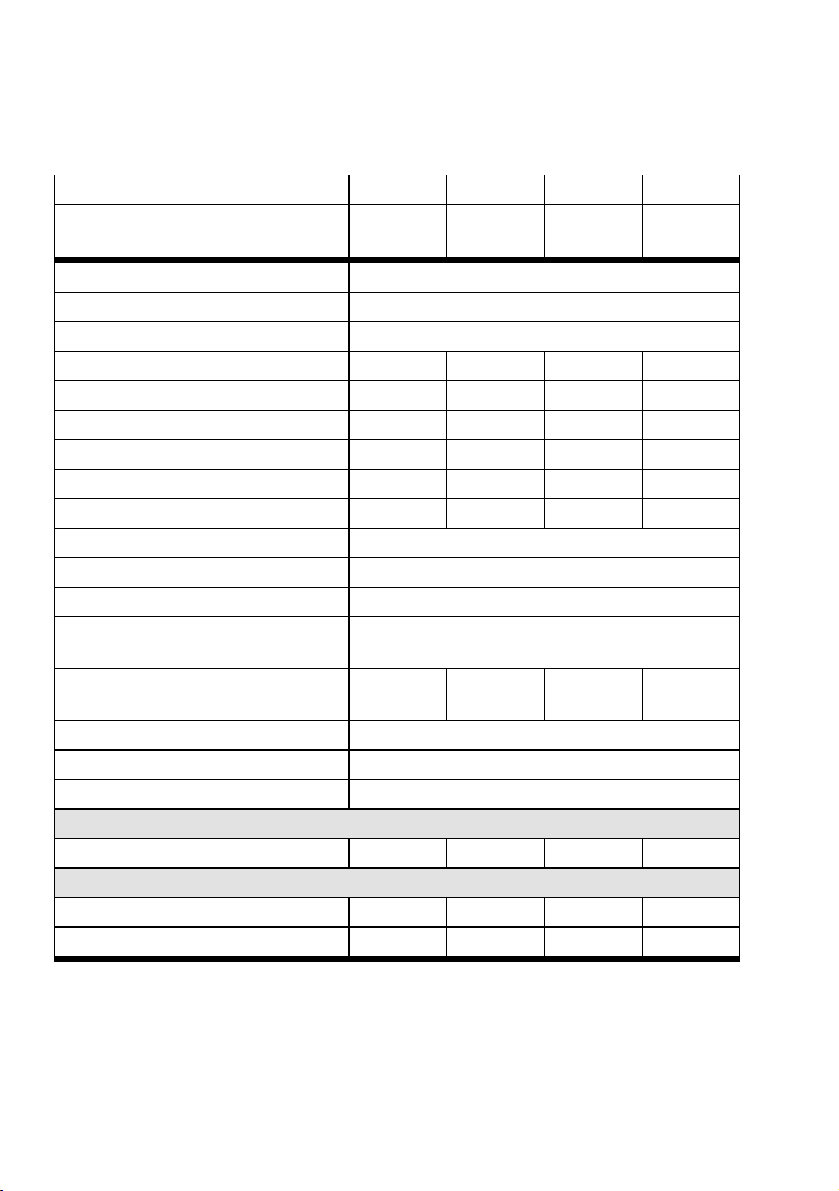
13 Technical data
1)
Size
Spindle pitch [mm/re-v]6 8 10 12
Design Electromechanical mini slide with ball screw drive
Guide Recirculating ball bearing guide
Mounting position Any
Max. perm. payload [kg] 1 2 6 10
Max. feed force F
x
Max. no-load driving torque
[N] 20 60 120 250
2)
[Nm] 0.008 0.014 0.026 0.069
Max. radial force on drive shaft [N] 30 75 180 230
Max. rotational speed [1/min] 4000 3750 3600 3000
Max. speed [m/s] 0.4 0.5 0.6 0.6
Max. acceleration [m/s2] 15
Repetition accuracy [mm] ± 0.015
Reversing backlash (new) [mm] < 0.15
Reversing backlash (critical limit)
Feed constant [mm/re-v]6 8 10 12
25 32 45 60
è 9 maintenance
Ambient temperature [°C] 0…+50
Storage temperature [°C] –20…+60
Degree of protection IP40
Max. perm. forces at the midpoint of the guide
Fy = F
z
[N] 669 991 1314 4937
Max. permissible torques at the midpoint of the guide
M
x
My = M
z
1)
The "PositioningDrives" engineering software is available for sizing tasks èwww.festo.com/sp.
2) at a speed of 0.05 m/s.
[Nm] 2 3.4 8.1 20
[Nm] 2.1 3.2 7 30
Tab. 7
16 Festo — EGSC-BS-KF — 2018-11c
Page 17

Technical data
Size 25 32 45 60
Geometric characteristics
H13 [mm] 7.3 7.9 10.2 15.9
L6 [mm] 25.1 31.8 37.3 53.4
Determination of the load compensation factor for combined
loads:
Materials
Note on materials Contains materials that include PWIS
1)
Profile, slide Anodised aluminium
Guide, screws, ball
Steel
bearing, spindle
Coverings PA, NBR
Weight
Zero stroke length [kg] 0.176 0.331 0.608 1.555
Per 100mm stroke [kg] 0.186 0.305 0.629 0.95
1) PWIS = paint-wetting impairment substances
Tab. 8
17Festo — EGSC-BS-KF — 2018-11c
Page 18

Reproduction, distribution or sale of this document or communication of its contents to others without express authorization is
prohibited. Offenders will be liable for damages. All rights
reserved in the event that a patent, utility model or design patent
is registered.
Copyright:
Festo AG & Co. KG
Ruiter Straße 82
73734 Esslingen
Germany
Phone:
+49 711 347-0
Fax:
+49 711 347-2144
e-mail:
[email protected]
Internet:
www.festo.com
 Loading...