

Page 1
DRRD-08/10
Festo AG & Co. KG
Postfach
73726 Esslingen
Germany
+49 711 347-0
www.festo.com
Operating instructions 8030937
1310NH
[8030939]
Original: de
Semi-rotary drive DRRD-8/10 English....................................
Note
Installation and commissioning may only be performed in accordance with these
instructions by technicians with appropriate qualifications.
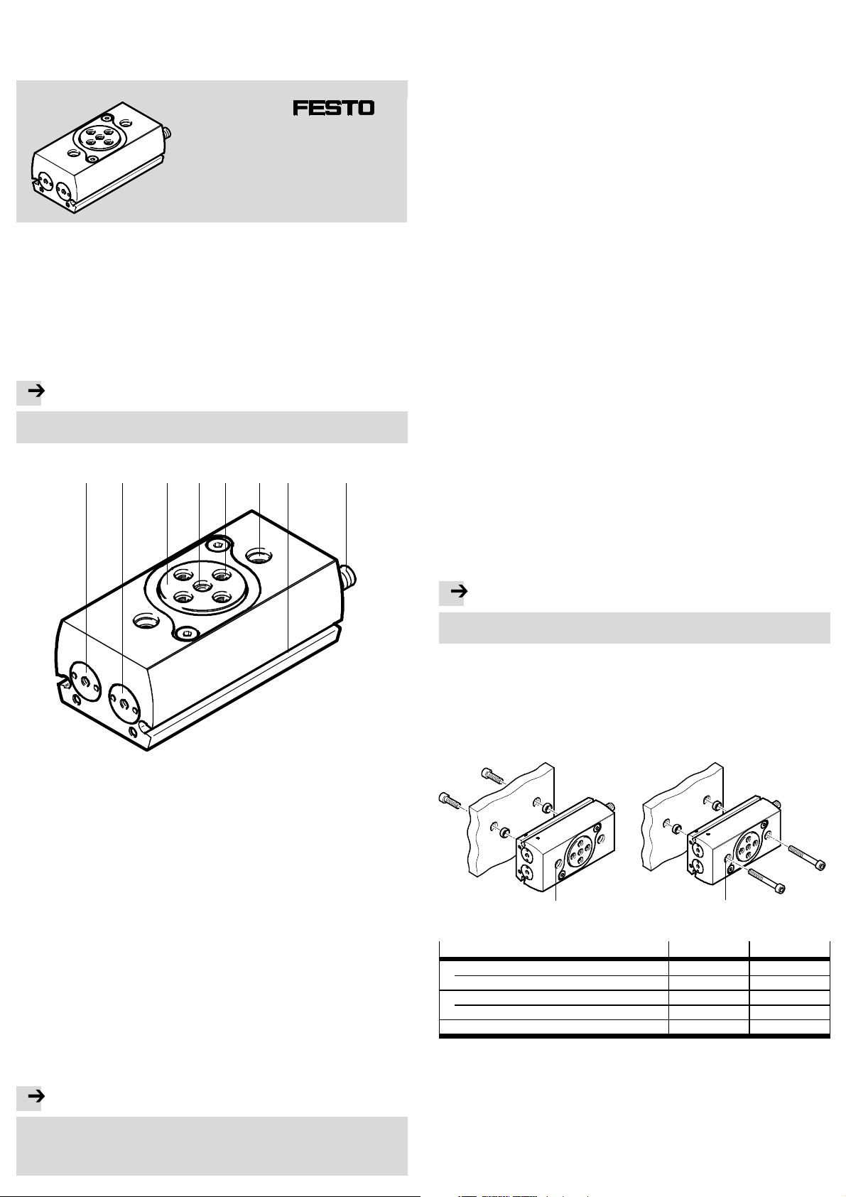
1 Control sections and connections
1 234
67 8
5
• Take into consideration the legal regulations applicable for the destination, as
well as:
– regulations and standards,
– regulations of the testing organizations and insurers,
– national specifications.
• Observe the warnings and notes on the product and in the relevant operating
instructions.
• Remove all transport packaging, such as transparencies, caps and cartons
(with the exception of any covers in the pneumatic ports).
The packaging is intended for recycling
(exception: oil paper = residual waste).
• Take into account the materialspecifications ( 11 Technical data).
• Use the product in its original status, without any unauthorised product modifications.
• Take into consideration the ambient conditions at the location of use.
Corrosive elements in the environment (e.g. ozone) will reduce the service life of
the product.
• Compare the limit values specified in these operating instructions with your
actual application (e.g. pressures, forces, torques, temperatures, masses,
speeds, etc.).
Operation of the product in compliance with the relevant safety regulations is
contingent on adherence to the load limits.
• Take the tolerance of the tightening torques into account. Unless otherwise
specified, the tolerance is ± 20 %.
• Do not modify any screws or threaded pins unless this is requested in these
instructions. For safety reasons, they are fixed with a screw locking agent.
For vertical installation:
• Make sure that the drive has reached a stable position when it comes to a stop
(e.g. the lowest point or secured with external stops).
• Make sure there is a supply of correctly prepared compressed air
( 11 Technical data).
• Having selected a medium, stick with it for the entire life of the product
(e.g. always use unlubricated compressed air).
• Pressurize your entire system slowly.
There will then be no uncontrolled movements. For slow start-up pressurisation,
use on-off valve HEL.
1 Supply port
(swivel clockwise)
2 Supply port
(swivel anti-clockwise)
3 Flanged shaft
4 Shaft opening with centring recess
5 Payload mounting interface (4x)
6 Mounting interface DRRD (2x)
7 Slot for cylinder switch (2x)
8 Shock absorber for swivel angle
adjustment, secured with lock nut
(2x)
for through-feed of
cables/compressed
Fig. 1
2 Function and application
The DRRD semi-rotary drive is a double-acting twin-piston drive. Whe n the compressed air supply ports are pressurised reciprocally, two pistons arranged in parallel move in the opposite direction backwards and forwards. This linear motion is
converted through pinions into a swivel motion of the flanged shaft. The DRRD has
an elastic end-position c ushioning.
The DRRD semi-rotary drive is intended for swivelling payloads which have to execute a defined angular movement.
4 Installation
4.1 Mechanical installation
Note
• Handle the DRRD with care to prevent damage to the flanged shaft. This applies in particular to the following points:
1. Position the DRRD so that you can easily reach the control sections and connections.
2. Secure the DRRD at the mounting interface 6 by using two screws and two
centring sleeves each.
Observe the tightening torque ( Fig. 3).
Direct mounting Through-hole fastening
6 6
Fig. 2
Size
Screw (direct mounting) M4 M4
Tightening torque [Nm] 3 3
Screw (through-hole fastening) M3 M3
Tightening torque [Nm] 1.2 1.2
Centring sleeve ZBH [mm] 7 7
8 10
Fig. 3
3 Requirements for product use
Note
Malfunction and material damage due to incorrect handling.
• Always comply with the specifications of this c hapter.
Only in this way can you ensure that the product functions correctly and
safely.
Page 2
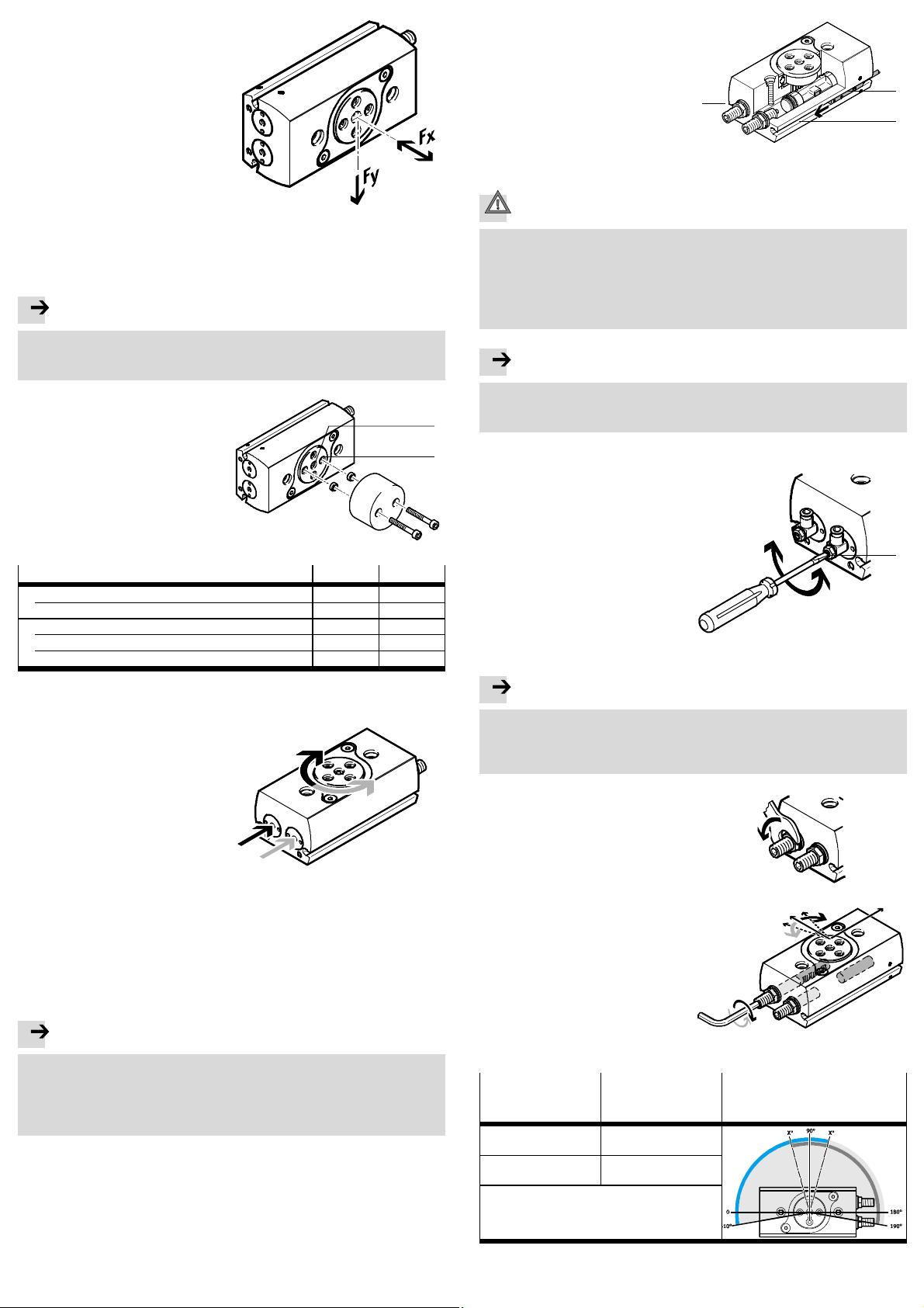
3. Pull tubing and cables through the
hollow flanged shaft, if necessary.
Diameter for wiring ( Fig. 6).
4. When mounting the payload, observe the following specifications:
– installation without tilting
– permissible radial force Fy
– permissible axial force Fx
– permissible mass moment of
inertia
– a structure that is as rotationally
symmetrical as possible.
Fig. 4
The mass moment of inertia of the payload should be calculated. Lever arms,
cantilevers and masses should be considered in the calculation (maximum permissible values www.festo.com/catalogue).
Note
If there are demanding requirements for concentricity of the components on the
flanged shaft:
• Use the middle centring hole 4 as well as one of the 4 existing centring holes.
5. Secure the payload to the drive
flange at the mounting interface 5
by using at least two screws positioned opposite one another and
centring sleeves.
Observe the tightening torque
( Fig. 6).
Fig. 5
Size 8 10
Shaft opening 4 [mm] ∅ 3 ∅ 3
Centring sleeve ZBH for middle centring hole [mm] 5 5
Screw for thread at 5 M3 M3
Centring sleeve ZBH [mm] 5 5
Tightening torque [Nm] 1.2 1.2
Fig. 6
4.2 Pneumatic installation
• If necessary, remove the covers in the
pneumatic ports.
To adjust the swivel speed:
• Use the GRLA one-way flow control
valves.
These are screwed directly into the
compressed air supply ports.
Fig. 7
4
5
• Place the proximitysensors for
sensing the end positions into the
slots 7.
7
Fig. 8
5 Commissioning
Caution
Danger of injury from rotating loads.
• Make sure the DRRD is only set into motion with protective devices.
• Make sure that in the swivel angle of the DRRD
– nobody can reach in
– no foreign objects can enter
(e.g. by means of an individual protective guard).
Note
• Comply with the following prerequisites:
– the sh ock absorbers are secured with lock nuts
– the o perating conditions are within the permissible ranges.
5.1 Commissioning end-position adjustment
1. Rotate both upstream one-way flow
control valves (B):
– at first completely closed
– thenopenthemagain
approximately one turn.
2. Pressurize the drive optionally in one
of the following ways:
– slow pressurisation of one side
– simultaneous pressurisation of
both sides with subsequent
exhausting of one side.
Fig. 9
Note
Risk of damage!
If the shock absorber is unscrewed too far, it will result in the piston colliding
with the end cap with insufficient cushioning.
• Observe the permissible shock absorber settings ( Fig. 13).
3. Pressurize the corresponding port to
swivel the DRRD into the desired end
position.
4. Loosen the lock nut on the shock
absorber.
Fig. 10
(A)
7
(B)
For vertical installation and eccentric loads:
• Use the controlled check valve HGL or a compressed air spacer compensation
reservoir VZS.
In this way you can prevent the effective load from sliding down suddenly if
there is a sudden pressure drop.
4.3 Electrical installation
Note
Multiple switching cycles of proximity sensors are possible, dependent on the
design.
• Make sure the proximity sensors are always set to the first switching point.
To do this, push the cylinder switch (A Fig. 8) in from the slot end where the
piston to be sensed is located until the first switching occurs.
5. Turn the corresponding shock
absorber until the desired end
position adjustment has been
reached.
Fig. 11
Angle setting Reaction Setting range related to the
basic factory setting (example
DRRD-...-180)
Turn the shock absorber
clockwise
Turn the shock absorber
anti-clockwise
Reduce the swivel angle
Increase the swivel angle
Fig. 12
Page 3

The following settings are possible:
Size
Angle adjustment per rotation [°] 8.2 6.8
Max. shock absorber setting XPmax [mm] 11.9 13.8
Min. shock absorber setting XPmin [mm] 5 5
8 10
Fig. 13
6. Tighten the locking nut of the shock absorber. Observe the tightening torque:
Size
ß Internal hexagon socket [mm] 3 3
ß Lock nut [mm] 8 8
Tightening torque [Nm] 1 1
8 10
Fig. 14
7. Repeat the procedure to set the second end position.
5.2 Carrying out commissioning
1. Start a test run at low swivel speed.
2. When conductingthe test run, check whether the DRRD settings need to be
corrected. These could be:
– swivel angle of the payload ( Fig. 12)
– swivel speed of the payload.
3. Unscrew the one-way flow control valves (B) slowly again up to the desired swivel speed.
4. Interrupt the test run if the piston can be heard to strike ha r d.
Causes of metallic striking may be:
– mass moment of inertia of the payload too high
– swivel speed of the payload too high
– no compressed air cushion on the exhaust side
– Shock absorber unscrewed too far (maximum values Fig. 13).
5. Make sure you remedy the above-named causes.
6. End the test run when all of the necessary corrections have been detected.
7 Maintenance and care
To check functioning of cushioning:
• Carry out the following steps:
DRRD-...
Tes t in t e r va l 2 million switching cycles
Procedure 1. Check the function of the shock absorbers.
Replacement interval
P
In case of audible bottoming out or rebounding:
2. Replace th e cushioning componentsand seals (lubricate the cushioning
components before installation with, for example, LUB-KC1).
If there is evidence of wear (bottoming out)
Fig. 16
If the piston can be heard to strike hard in the end position:
• In case of wear, replace the internal cushioning components of the DRRD
( 8 Disassemblyand repair).
• If the DRRD is c ontaminated, clean it with a soft cloth.
Permissible cleaning agents include:
– warm soap suds up to + 60 °C
– petroleum ether
– all non-abrasive cleaning agents.
8 Disassembly and repair
For eccentric masses on the lever arm:
Caution
Danger of injury from masses dropping suddenly.
• Make sure the payload has reached a stable position before venting (e.g. the
lowest point).
• Make sure that the semi-rotary drive is exhausted for disassembly.
• Recommendation: Send the product to o ur re pair service.
This way, the required fine tuning and tests will be taken into special consideration.
• Information about spare parts and accessories can be found at:
www.festo.com/spareparts.
6Operation
Caution
Danger of injury from moving masses.
• Make sure that in the swivel angle of the DRRD
– nobody can reach in
– no foreign objects can enter
(e.g. by means of an individual protective guard).
In the case of several uninterrupted swivel cycles:
Note
Operational reliability can be impaired by an excessive temperature rise.
• Make sure that the following maximum swivel frequencyis not exceeded.
Size
Maximum swivel frequency [Hz] 2.2 2.1
8 10
Fig. 15
To replace the integrated cushioning components
( 9 Accessories):
• Carry out the following steps:
1. Vent the DRRD.
2. Measure the positionof the shock absorber
(dimensionXP) and loosen the lock nut on the
shock absorber 8.
3. Unscrew the shock absorber, lubricate the new
cushioning component (e.g. with LUB-KC1) and
assemble. Use new sealing discs (C Fig. 17) if
required.
4. Screw in shock absorbers up to dimension XP
( point 2).
5. Check the angle adjustment and c orrect,
if necessary.
6. Tighten the lock nut on the shock absorber 8
(tightening torque Fig. 14).
9 Accessories
Note
• Select the corresponding accessories from our catalogue
www.festo.com/catalogue.
(C)
Fig. 17
Page 4

10 Fault clearance
Malfunction
Uneven movement of the
payload
Hard metal impact at the end
position
Flanged shaft does not remain
in th e end position
(rebounding)
Possible cause Remedy
Flow control valves inserted
incorrectly
Asymmetric angle setting Symmetric setting preferred
DRRD defective Return to Festo
Residual energy too high Select a lower swivel speed
Semi-rotary drive moves
against an unpressurized
chamber
Shock absorber unscrewed
too far
Cushioning component
defective/worn
Check the flow control
function (supply or exhaust air
flow control)
Move only against residual air
cushionontheexhaustside
Select a lighter load
Pressurize semi-rotary drive
on both sides
Observe the maximum
permissible unscrewing length
Replace cushioning component
( 8 Disassembly and repair)
Fig. 18
11 Technical data
Size
Design Semi-rotary drive with twin pistons
Cushioning Elastic cushioning rings/plates at both ends
Pneumatic por t M3
Operating medium Compressed air to ISO 8573-1:2010 [7:4:4]
Note on the operating medium Lubricated operation possible (in which case
Operating pressure [bar] 3…8
Mounting position any
Swivel angle [°] 180
Setting range on both sides [°] infinitely adjustable between –100 … +10
Cushioning angle (Z minimum swivel
angle)
Repetition accuracy [°] ≤ 0.03
Ambient temperature [°C] –10 … +60
Theoretical to rque at 6 bar [Nm] 0.2 0.4
Max. axial load (static)
Ten s ion [kN] 0.26
Pressure [kN] 0.7 1.1
Max. permissible axial and radial
force on flanged shaft
Max. permissible mass moment of
inertia
End-position adjustment by turning the cushioning components
Note on materials Contains paint-wetting impairment substances
Materials
Housing Anodised aluminum
Flanged shaft, plug, shock absorber
retaining plate, screws
Seals TPE-U (PU), NBR
Product weight [kg] 0.16 0.25
8 10
lubricated o peration will always be required)
[°] 38 37
dependent on the distance of the force
application point ( www.festo.com/catalogue)
[kgcm2] 15 20
(PWIS)
Steel
Fig. 19
 Loading...