

Page 1
DGP(L)-…-B
Festo AG & Co. KG
Postfach
D-73726 Esslingen
++49/711/347-0
www.festo.com
Bedienungsanleitung 757170
1012h
Original: de
Linearantrieb DGP(L)-…-B Deutsch......................................
Hinweis
Einbau und Inbetriebnahmenur von qualifiziertem Fachpersonal, gemäß
Bedienungsanleitung.
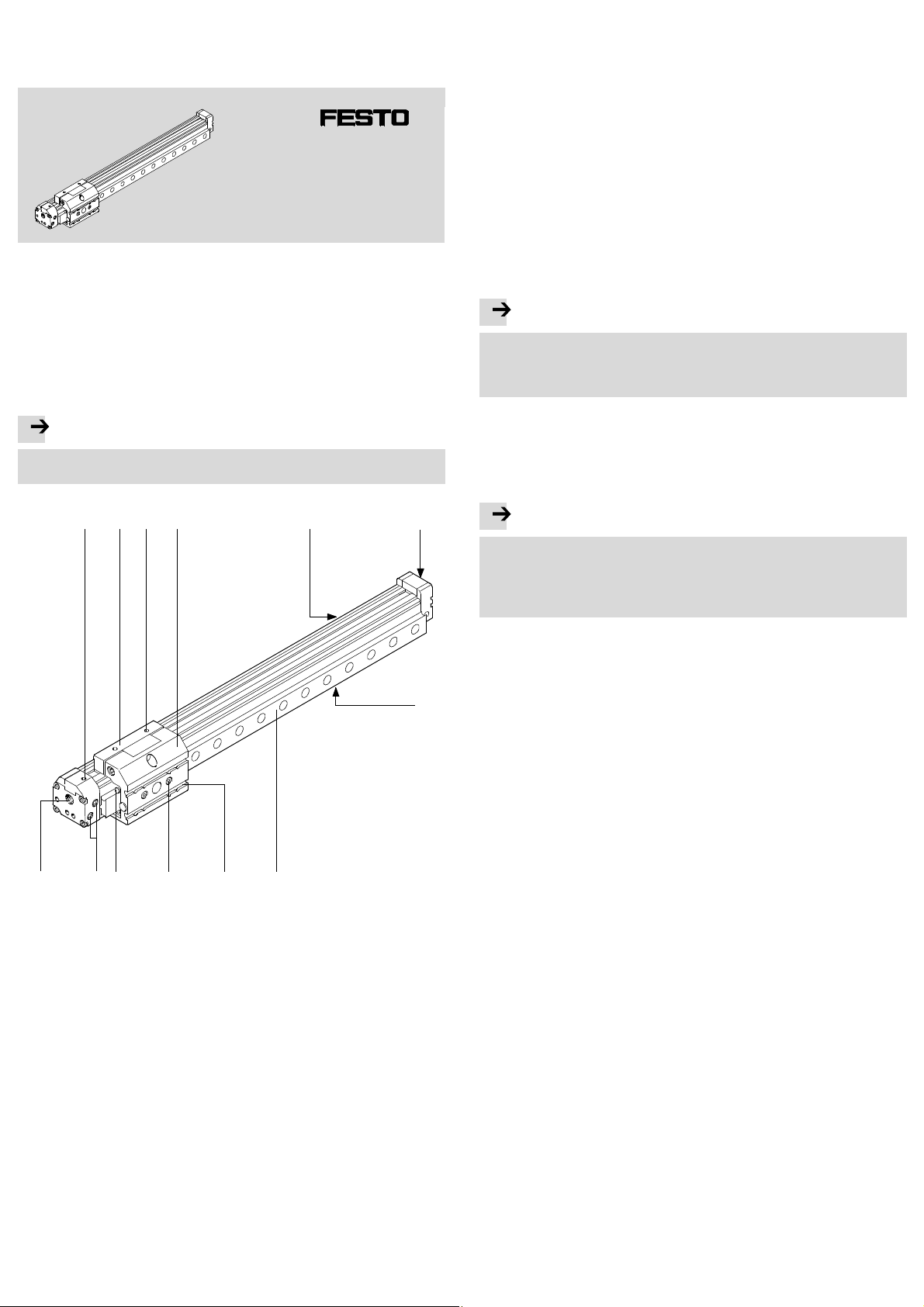
1 Bedienteile und Anschlüsse
1 32 4 5 6
2 Funktion und Anwendung
Durch wechselweise Belüftung der Druckluftanschlüsse bewegt sich der Innenläufer im Rohr hin und her. Durch eine starre Verbindung bewegt sich der Außenläufer
mit. Den dazu notwendigen Schlitz im Zylinderrohr überspannt ein Bandsystem.
Bestimmungsgemäß dient das Produkt zum Massetransport.
Das drucklose Bewegen des Schlittens ist nur zur Störungsbeseitigung und mit
geringer Geschwindigkeit zugelassen. Bei zu hoher Geschwindigkeit kann der entstehende Unterdruck das Dichtband in den Kolbenraum zieh en. Dies führt zu:
– hoher Leckage und
– unzulässigen Beschleunigungen (z. B. bei senkrechter Einbaulage).
Unterscheiden Sie die Einsatzfälle:
– als Zylinder:
Im Normalbetrieb durchfährt der Läufer den gesamten Hub von Endlage zu Endlage.
– als servopneumatische Positionierachse:
Gesteuert durch ein Regelgerät fährt der Läufer im Normalbetrieb beliebige
Zwischenpositionen an.
Bei Einsatz des DGP(L) als servopneumatische Positionierachse:
Hinweis
• Überspringen Sie die Abschnitte, die mit “nur Zylinder” gekennzeichnet sind.
Sonst treten Positionierprobleme auf.
• Beachten S ie die Hinweise in den Beschreibungender verwendetenPositioniercontroller (z. B. SPC11/SPC200).
3 Transport und Lagerung
• Berücksichtigen Sie das Gewicht des DGP(L).
Je nach Ausführung wiegt der DGP(L) über 80 kg.
4 Voraussetzungen für den Produkteinsatz
Hinweis
Durch unsachgemäßenGebrauch entstehen Fehlfunktionen.
• Stellen Sie sicher, dass die Vorgaben dieses Kapitels stets eingehalten
werden.
• Berücksichtigen Sie die Warnungen und Hinweise am Produkt und in den
zugehörigenBedienungsanleitungen.
aC
1 Stellschraube für Endlagen-
2 Mitnehmer
3 Gewinde für Nutzlast
4 Schlitten
5 Nut mit Aussparung für
6 Gewinde zur Befestigung des
Fig. 1
aB
aA
dämpfung PPV
(nicht bei DGPL)
Näherungsschalter
DGP(L) (4x)
aJ
7
9 8
7 Nut ohne Aussparung für Nuten-
steine
8 Führungsschiene (nur DGPL)
9 Nut zur Befestigung der Nutzlast
aJ Gewinde für Nutzlast und
Zentrierung
aA Schmiernippel (nur DGPL-…-KF)
aB Druckluftanschluss indirekt
(nicht bei …-D2)
aC Druckluftanschluss direkt
• Vergleichen Sie die Grenzwerte in dieserBedienungsanleitung mit denen Ihres
Einsatzfalls (z. B. Kräfte, Momente,Temperaturen, Massen).
Nur die Einhaltung der Belastungsgrenzen ermöglicht ein Betreibendes Produkts gemäß der einschlägigen Sicherheitsrichtlinien.
• Berücksichtigen Sie die Umgebungsbedingungen am Einsatzort.
Korrosive Umgebungen verkürzen die Lebensdauer des Produkts (z. B. Ozon).
• Berücksichtigen Sie die Vorschriften der Berufsgenossenschaft, des
Technischen Überwachungsvereins,des VDE oder entsprechende nationale
Bestimmungen.
• Verwenden Sie das Produkt im Originalzustandohne jegliche eigenmächtige
Verände rung.
• EntfernenSie die Verpackungenwie Folien, Kappen, Kartonagen.
Ausnahme: Haftetiketten an Druckluftanschlüssen (Verschmutzungsgefahr).
Die Verpackungensind vorgesehenfür eine Verwertung auf stofflicher Basis
(Ausnahme: Ölpapier = Restmüll).
• Lassen Sie die Abdeckkappen aus blauem Kunststoff an den Abschlussdeckeln
aufgesteckt. Diese schützen die Spannvorrichtung des Bandsystems gegen
äußere Einflüsse.
• Sorgen Sie für Druckluft mit ordnungsgemäßer Aufbereitung Tec hn i s c he
Daten.
• Berücksichtigen Sie die Toleranz der Anziehdrehmomente. Ohne spezielle
Angabe beträgt die Toleranz±20 %.
5 Einbau
5.1 Einbau mechanisch
• Vermeiden Sie, dass das Bandsystem beschädigt wird.
Beschädigungenam Bandsystem führen zu Leckage und mindern die Leistungsfähigkeit des DGP(L).
• Vermeiden Sie das Eindrücken bzw. Einsaugen des Dichtbands.
Schäden am Dichtband mindern die Betriebszuverlässigkeit. Durch ruckartiges
Bewegen des drucklosen Schlittens kann ein Unterdruck entstehen, der das
Dichtband in den Kolbenraum saugt.
• Lassen Sie Schrauben und Gewindebolzen grundsätzlich unverändert, sofern Sie
in dieserAnleitung nicht dazu aufgefordert werden.
• Achten Sie auf einen Einbau ohne Verspannungenund Biegungen.
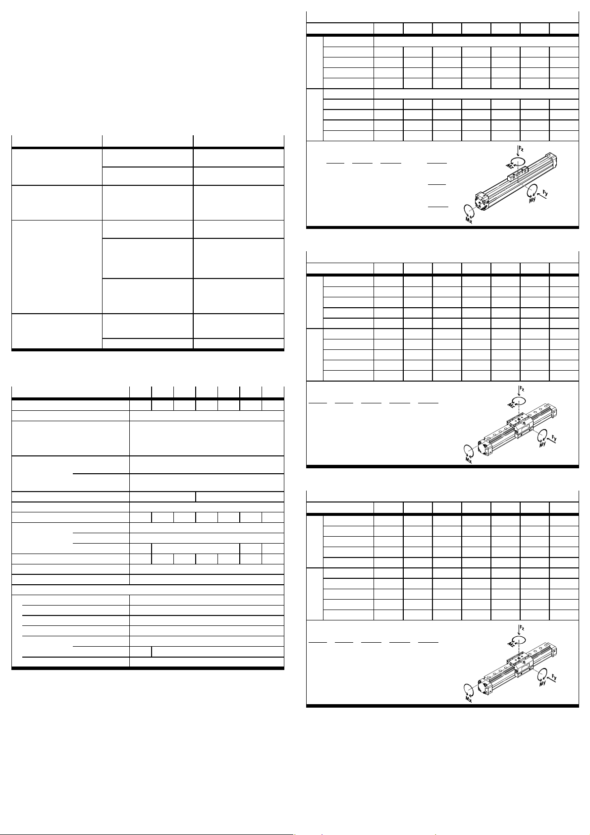
• Verwenden Sie die Mittenstütze (Profilbefestigung) MUP mit folgenden Stützabständen (l) ( Fig. 2).
Page 2

F
4
3
2
1
1 DGP…-18
2 DGP…-25
3 DGP…-32
4 DGP…-40
F
l l
3
2
1
1 DGP…-50
2 DGP…-63
Fig. 2: Notwendige Stützabstände
Bei Anbau von MittenstützenMUP:
1. PositionierenSie die Profilbefestigungen gleichmäßig über die gesamte Antriebslänge verteilt, nicht
nur über die Hubstrecke.
2. Platzieren Sie den DGP(L) so, dass alle Bedienteile
erreichbar sind.
3. Platzieren Sie die Mittenstütze am DGP(L) nach
Fig. 3.
Durch Verkippen gleiten die Nutensteine bei den
Baugrößen 32 … 80 an jeder Stelle des Profils in die
Nut.
4. Drehen Sie die Klemmschrauben gleichmäßig fest.
Anziehdrehmomente [Nm]
MUP-18/25 MUP-32 MUP-40 MUP-50 MUP-63 MUP-80
3 4,5 5,5 18 18 18
Fig. 4
5. Stellen Sie sicher, dass die Mittenstütze nicht mit
dem Schlitten bzw. der Nutzlast kollidiert (insbesondere bei seitlicher Befestigung). Schieben
Sie den S chlitten mit der Nutzlasthierfür einmal
über die gesamte Verfahrstrecke.
3 DGP…-80
DGP(L)-18 … 25
DGP(L)-32 … 80
Fig. 3
F
Zur Befestigung der Nutzlast:
• Wählen Sie eine Befestigungsmöglichkeit:
DGP
1. Durchgangsbohrungenund Gewindebohrungen im Mitnehmer
( Fig. 1)
Fig. 7
• B eachten Sie bei der Auslegung Ihrer Schra ubverbindung zur Befestigung der
Nutzlast die folgenden maximalen Anziehdrehmomente:
Anziehdrehmomente [Nm]
DGP(L) 18 25 32 40 50 63 80
DGP M5 3,5 3,5 3,5 – – – –
M6 – – – 6 – – –
M8 – – – – 12 12 –
M12 – – – – – – 30
DGPL M5 4,5 4,5 4,5 5 – – –
M8 – – – – 15 15 15
Fig. 8
• Im Falle von Befestigungsmöglichkeit mit DGPL
müssen die Schrauben kürzer als die Gewindebohrung sein.
Bei Nutzlastenmit eigener Führung:
• Just ie ren Sie die Führungen von Nutzlast und DGP(L) exakt parallel.
Nur so vermeiden Sie Überlastungen am Schlitten 11 Technische Daten:
zul. Kräfte.
5.2 Einbau, pneumatisch
Bei Einbauin senkrechter oder schräger Lage:
War nung
Im Falle eines Druckabfalls fällt die bewegliche Masse nach unten: Gefahr von
Quetschungen!
• Lesen Sie die Beschreibungen der verwendeten Positioniercontroller (z. B.
SPC11/SPC200). Dort findenSie pneumatische Sc haltpläne, mit denen das
Herabfallen verzögert werden kann (nur bei servopneumatischem Positionieren).
• Prüfen Sie, ob Rückschlagventile HGL erforderlich sind (nur bei Verwendung
als Zylinder). Dadurch vermeiden Sie, dass die bewegliche Masse schlagartig
abgleitet.
• Prüfen Sie, ob Sicherungsmaßnahmen gegen langsames Absinken durch
Leckage erforderlich sind (z. B. Zahnklinken oder bewegte Bolzen).
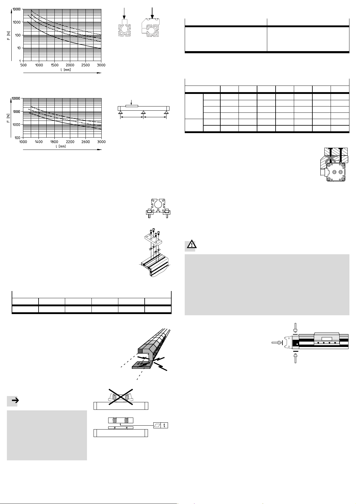
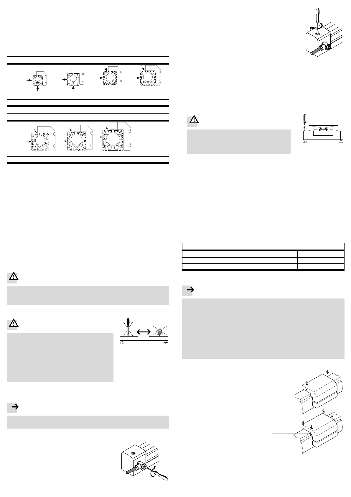
• Wählen Sie die Druckluftanschlüsse.
Zu den ab Werk vorgesehenen Druckluftanschlüssen (A) existieren Alternativanschlüsse (B, C). In diesen
sitzen Verschlussschrauben.
A = Druckluftanschlüsse ab Werk
B, C = Alternativanschlüsse
DGPL
1. Nutensteine NSTL am Schlitten
2. Gewindebohrungen und Zentrierelemente ( 9 Zubehör) am
Schlitten
Fig. 9
B
A
Fig. 10
C
Bei harten und steifen Nutzlasten:
Hinweis
Ein Verbiegen des Schlittens aufgrund
einer gekrümmten Nutzlast mindert
die Lebensdauer der Führung.
• Stellen Sie sicher, dass die Montagefläche der Nutzlast folgende
Ebenheit (t) aufweist:
–GF:t≤ 0,03 mm
–KF:t≤ 0,01 mm
Fig. 6
Fig. 5
Bei Variante …-D2 (mit beidseitigem
Luftanschluss) kann der Luftanschluss nicht einseitig vorgenommen
werden.
Zum Einstellen der Geschwindigkeit (nur Zylinder):
• Verwenden Sie Drossel-Rückschlagventile vom Typ GRLA.
Bei Hublängen > 500 mm:
Bei Ansteuerung des DGP(L) mit Hilfe von SPC11 oder SPC200 muss die Drucklufteinspeisung beidseitig erfolgen (Variante …-D2).
Nur die beidseitige Einspeisung garantiert optimale Dynamik.
Page 3

5.3 Einbau, elektrisch
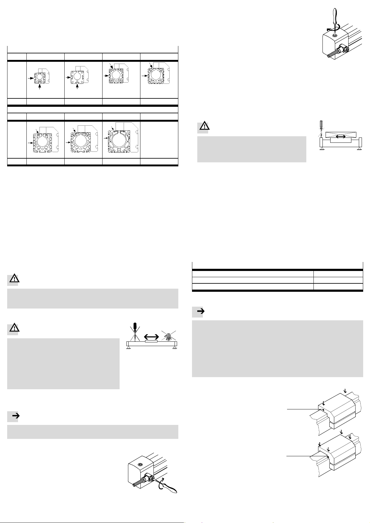
Bei Positionsabfrage mit Näherungsschaltern:
• A chten Sie darauf, dass der Mindestabstand L zwischen statischen oder bewegten ferritischen Massen und den Näherungsschaltern den in Tabelle Fig. 11
angegebenen Werten entspricht.
Dadurch vermeiden Sie Fehlschaltungen durch Fremdbeeinflussung.
Mindestabstände L [mm]
DGP(L) 18 25 32 40
POS
L 40 4,2 4,8 5,6
Bei Verwendung der internen EndlagendämpfungPPV:
2. Drehen Sie die Stellschrauben für die interne Endlagendämpfung PPV
– beidseitig zunächst ganz zu,
– dann wieder eine Umdrehung auf.
Fig. 14
3. Belüften Sie den DGP(L) wie folgt:
– Zunächst gleichzeitig auf beiden Seiten. Dadurch bewegt sich der Schlitten
geringfügig bis zu einem Gleichgewichtspunkt.
– Entlüften S ie den DGP(L) anschließendauf einer Seite. So vermeiden Sie
Spitzenbelastungen am DGP(L) und im Druckluftnetz.
4. Starten Sie einen Probelauf.
5. Prüfen Sie, ob die Schlitten-Geschwindigkeit verändert werden muss.
DGP(L) 50 63 80
POS
L 11,4 14 5
Fig. 11 (POS = Position des Näherungsschalters)
• Verwenden Sie Nutabdeckungen zur Vermeidung von Verschmutzung in den
Sensornuten.
6 Inbetriebnahme
6.1 Inbetriebnahme Gesamtanlage
• Belüften Sie die Anlage insgesamt langsam. Dadurch vermeiden Sie Bewegungen unkontrollierter Art.
Zur langsamen Einschaltbelüftung dient das Druckaufbau-VentilHEL.
6.2 Vorbereitung der Inbetriebnahme
Bei Nutzlastenoder Schlittengeschwindigkeitenhoher und mittlerer Größe:
• Verwenden Sie Dämpfungselemente ausreichender Dimensionierung.
Ohne externe Abfangvorrichtungenverträgt der DGP(L) maximale Geschwindigkeiten und Nutzlasten gemäß Katalogangaben.
War nung
Ohne externe Abfangvorrichtungenkann ein Überschreiten der im Katalog
angegebenen Grenzwerte zur Zerstörung des DGP(L) führen.
• A uch bei Störungen dürfen die Grenzwerte nicht überschritten werden.
Vor jeder Inbetriebnahme und im Betrieb:
War nung
Stellen S ie sicher, dass im Verfahrbereich
– niemand in die Laufrichtung der bewegten Bau-
teile greifenkann (z. B. durch Schutzgitter).
Fig. 12
– sich keineFremdgegenstände befinden.
Nur bei völligem Stillstand der Masse darf ein
Greifen an den DGP(L) möglich sein.
6.3 Durchführungder Inbetriebnahme
Zur Inbetriebnahme des DGP(L) als servopneumatische Positionierachse:
Hinweis
• Vollziehen S ie die Inbetriebnahme gemäß den VorgabenIhres Positioniersystems.
Zur Inbetriebnahme des DGP(L) als Zylinder:
1. Drehen Sie die Drossel-Rückschlagventile
– für die beiden Seiten zunächst ganz zu,
– dann wieder eine Umdrehung auf.
Bei Masse-Geometrienmit Überstand:
War nung
Kollisionsgefahr !
• B erücksichtigen Sie, dass die Stellschrauben
des DGP(L) nur bei Stillstand des Schlittens verdreht werden dürfen.
Fig. 15
6. Drehen Sie die Drossel-Rückschlagventile langsam auf, bis die gewünschte
Schlitten-Geschwindigkeit erreicht ist.
7. Drehen Sie die Stellschrauben für die interne Endlagendämpfung PPV auf.
Bestimmungsgemäß soll der Schlitten die Endlage erreichen, ohne hart anzuschlagen oder zurückzufedern.
7WartungundPflege
Zur Pflege des Bandsystems:
• Reinigen Sie das Bandsystem bei Bedarf mit einem weichen Lappen.
Reinigungsmedien: alle werkstoffschonenden Medien.
• Fetten Sie das Bandsystem oberflächlich, falls es keine Fettschicht mehr aufweist. Fettsorte: LUB-KC1.
Zur Schmierungder Führung der Typen KF:
1. Stellen Sie sicher, dass die Schmierintervalle gemäß Fig. 16 eingehalten werden.
Schmierintervalle und Fettsorten
Erstintervall 5 000 km
Folgeintervall mit Spezialfett LUB-KC1 (silikonfrei) 400 km
Oder: Folgeintervall mit Spezialfett LUB-RN2 (silikonfrei) 5 000 km
Fig. 16
Hinweis
Das Schmierintervall ist abhängig von der Belastung des Produkts.
• Halbieren Sie das S c hmierintervall ( Fig. 16) wenn eine der folgenden
Situationen vorliegt:
– staubige und schmutzige Umgebung
– Nennhübe > 2m/s
– Umgebungstemperatur > 40 °C
– Betriebsalter des Produkts > 3Jahre.
Wenn mehrere Situationen gleichzeitig vorliegen, ist das Schmierintervall zu
vierteln.
2. Entlüften Sie den DGPL.
3. Fetten Sie die Wälzlager über die
DGPL-18-K F
Bohrungen aJ.
Dazu dient eine Fettpresse mit Nadel-Spitzmundstück oder alternativ
aJ
eine Einwegspritze mit Nadel.
• Schieben Sie den Schlitten während des Fettens hin- und her.
Sonst füllen sich die Fetträume
nicht gleichmäßig.
DGPL-...-KF
aJ
Fig. 13
Fig. 17
4. Fetten Sie die Führungsschiene oberflächlich, falls sie keine Fettschicht mehr
aufweist (Fettsorte Fig. 16).
Alternativbietet Ihnen Festo eine Inspektion als Serviceleistung inklusive des
Nachfettens an. Ansonsten ist der DGP(L) wartungsfrei.
Page 4
8 Reparatur
• Empfehlung: Schicken Sie das Produkt an unseren Reparaturservice.
Dadurch werden erforderliche Feinabstimmungen und Prüfungen besonders
berücksichtigt.
• Informationen über Ersatzteile und Hilfsmittel finden Sie unter:
www.festo.com/spareparts
9Zubehör
Wählen Sie bitte das entsprechende Zubehör aus unserem Katalog
www.festo.com/catalogue/DGP
10 Störungsbeseitigung
Störung
Ungleichförmige Bewegung
des Schlittens
Störungen bei der Positionsabfrage
Starke Leckage Zylinder verspannt eingebaut Zylinder auf ebenem Un-
Zylinder erreicht nicht die gewünschte Geschwindigkeit
Mögliche Ursache Abhilfe
Drossel-Rückschlagventile
falsch eingesetzt
Führungsschiene nicht
gefettet
Ferritische Teile in der Nähe
des Näherungsschalters
Dichtung verschlissen Verschleißteile ersetzen:
Dichtband eingedrückt/eingesaugt
Fehlendes Luftvolumen – Anschlussquerschnitte
Hohe Reibungoder Gegenkraft Grenzwerte einhalten
Möglichst die Abluft drosseln
(nicht die Zuluft)
Führungsschiene fetten
7 Wartung und Pflege
Teileaus nichtmagnetischen
Werkstoffen einsetzen oder
Mindestabstände einhalten
5.3 Einbau, elektrisch
tergrund befestigen.
– Selbstreparatur mit Ver-
schleißteilesatz
– zur Reparatur an Festo schi-
cken
Unterdruck im Kolbenraum
vermeiden (z. B. drucklosen
Schlitten nur langsam bewegen)
vergrößern
– Volumen vorschalten
Fig. 18
11 Technische Daten
DGP(L)
Pneumatischer Anschluss M5 GÁ GÁ G¼ G¼ GÅ G½
Funktionsweise doppeltwirkend
Einbaulage beliebig
Betriebsmedium Einsatz als
Betriebsdruck [bar] 2…8 1,5 … 8
Umgebungstemperatur [°C] –10 … +60
Theoretische Kraft bei 6 bar [N] 153 295 483 754 1 178 1 870 3 016
Geschwindigkeiten
DGPL
(min … max)
Dämpfungslänge PPV [mm] 16 18 20 30 30 30 85
Dämpfung PPV pneumatische Dämpfung beidseitig einstellbar
Max. Energie Diagramme Katalogangaben
Werkstoffe
Abschlussdeckel/Profil Aluminium,eloxiert
Abdeckband Stahl
Mitnehmer Aluminium, eloxiert
Schlitten Aluminium,eloxiert
Führungs-
schiene
Dichtungen Nitrilkautschuk, Polyurethan
Zylinder:
Einsatz als
Positionierachse:
GF [m/s] 0,05 … 1
KF [m/s] 0,2 … 3
GA [m/s] – 0,2 … 3 – –
GF Aluminium, elo xiert
KF Stahl Stahl, korrosionsgeschützt
18 25 32 40 50 63 80
(Empfehlung bei Hublängen > 2 000 mm und horizontalem Einbau: DGP(L) mit Dichtband nach unten einbauen)
Druckluft nach ISO 8573-1:2010 [7:–:–]
Druckluft nach ISO 8573-1:2010 [6:4:4]
Fig. 19
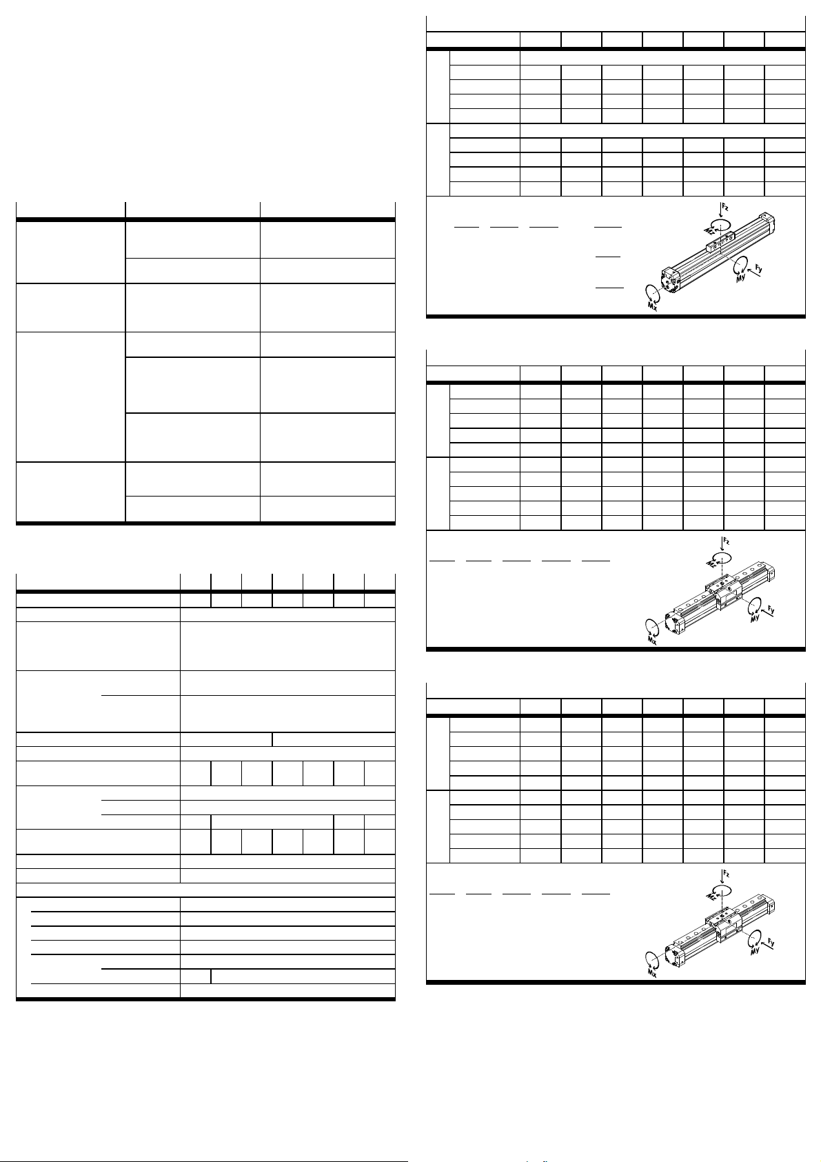
Zulässige Kräfte- und Momentenbelastung
DGP 18 25 32 40 50 63 80
GK Fymax [N] –
Fzmax 120 330 480 800 1 200 1 600 5 000
Mxmax [Nm] 0,5 1 2 4 7 8 32
Mymax 11 20 40 60 120 120 750
Mzmax 1 3 5 8 15 24 140
GV Fymax [N] –
Fzmax 120 330 480 800 1 200 1 600 –
Mxmax [Nm] 1 2 4 8 14 16 –
Mymax 22 40 80 120 240 240 –
Mzmax 2 6 10 16 30 48 –
Formelfür kombinierte Belastungen:
0, 4 ×
Fz
+
Fz
Mx
max.
Mx
max.
My
+
+ 0, 2 ×
My
max.
Mz
≤ 1
Mz
max.
Fz
≤ 1
Fz
max.
Mz
≤ 1
Mz
max.
Fig. 20
Zulässige Kräfte- und Momentenbelastung
DGPL-GF 18 25 32 40 50 63 80
GK Fymax [N] 340 430 430 1 010 1 010 2 000 2 000
Fzmax 340 430 430 1 010 1 010 2 000 2 000
Mxmax [Nm] 2,2 5,4 8,5 23 32 74 100
Mymax 10 14 18 34 52 140 230
Mzmax 10 14 18 34 52 140 230
GV Fymax [N] 330 400 395 930 870 1 780 –
Fzmax 330 400 395 930 870 1 780 –
Mxmax [Nm] 2 5 8 21 28 66 –
Mymax 18 25 30 58 83 235 –
Mzmax 18 25 30 58 83 235 –
Formelfür kombinierte Belastungen:
Fy
Fz
+
Fy
max.
+
Fz
Mx
max.
Mx
max.
My
max.
Mz
+
≤ 1
Mz
max.
+
My
Fig. 21
Zulässige Kräfte- und Momentenbelastung
DGPL-KF 18 25 32 40 50 63 80
GK Fymax [N] 930 3 080 3 080 7 300 7 300 14 050 14 050
Fzmax 930 3 080 3 080 7 300 7 300 14 050 14 050
Mxmax [Nm] 7 45 63 170 240 580 745
Mymax 23 85 127 330 460 910 1545
Mzmax 23 85 127 330 460 910 1545
GV Fymax [N] 930 3 080 3 080 7 300 7 300 14 050 –
Fzmax 930 3 080 3 080 7 300 7 300 14 050 –
Mxmax [Nm] 7 45 63 170 240 580 –
Mymax 45 170 250 660 920 1 820 –
Mzmax 45 170 250 660 920 1 820 –
Formelfür kombinierte Belastungen:
Fy
Fz
+
Fy
max.
+
Fz
Mx
max.
Mx
max.
My
max.
Mz
+
≤ 1
Mz
max.
+
My
Fig. 22
Page 5

DGP(L)-…-B
Festo AG & Co. KG
Postfach
D-73726 Esslingen
++49/711/347-0
www.festo.com
Operating instructions 757170
1012h
Original: de
Linear drive DGP(L)-…-B English........................................
2 Function and application
When the compressed air ports are pressurized alternately, th e piston moves backwards and forwards in the tubing. By means of a rigid connection, the outer slide
also moves. The slot in the cylinder barrel required for this is covered by a band
system.
This product has been designed for transporting mass loads.
Pressureless movement of the slide is only approved when eliminating faults and
at a low speed. If excessive speed is used, the vacuum which results can pull the
sealing band into the pistonchamber. This can lead to:
– high leakage and
– non-permitted acceleration (e. g. when installed vertically).
The following distinctions are made:
– as cylinder:
In normaloperation the slide traverses the complete stroke from one end
position to the other.
– as servopneumaticpositioning axis:
When controlled by a controller, the slide can move to any intermediate position
in normaloperation.
Using the DGP(L) as a servopneumatic positioning axis:
Note
• Omit the sections which are marked “Only cylinder”. Otherwise positioning
problems will occur.
• Observe the instructions in the manuals for the positioning controller used
(e.g. SPC11/SPC200).
Note
Fitting and commissioning is to be carried out only by qualified personnel in
accordancewith the operating instructions.
1 Control sections and connections
1 32 4 5 6
aC
1 Adjusting screw for end position
2 Driver
3 Thread for effec tive load
4 Slides
5 Groove with recess for proximity
6 Thread for fastening the DGP(L)
7 Groove without recess for sliding
Fig. 1
aB
cushioning
(not for DGPL)
switch
(4x)
blocks
aA
aJ
9 8
8 Guide rail (DGPL only)
9 Groove for fastening the effective
load
aJ Thread for effec tive load and
centring
aA Lubricating nipple
(DGPL-…-KF only)
aB Compressed air port indirect
(not for …-D2)
aC Compressed air port direct
7
3 Transport and storage
• Consider the weight of the DGP(L).
Depending on the design, the DGP(L) can weigh over 80 kg.
4 Requirementsfor productuse
Note
Malfunctions will occur if the device is incorrectly used.
• Be sure to always complywith the specifications in this chapter.
• Note the warnings and instructions on the product and inthe relevant operating instructions.
• Compa re the maximum values specified in these operating instructions with
your actual application (e.g. forces, torques, temperatures, masses).
Only compliance with the load limits allows operation of the product in
compliance with the relevant safety regulations.
• Take into consideration the ambient conditions at the location of use.
Corrosive elements in the environment (e.g. ozone) will reduce the service life of
the product.
• Please comply with national and local safety laws and regulations.
• Use the product in its original condition without any unauthorised modifications.
• Remove all transport packing such as foils, caps, cardboard.
Exception: adhesive labels on compressed air ports (danger of dirt entering the
tubing)
The packingis intended for recycling (except for: oiled paper = other waste).
• Leave the blue plastic cover caps fitted on the end c aps. These protect the
clamping device of the band system from external influences.
• Ensure tha t the compressed air is properly prepared Technical data.
• Take the tolerance of the tighteningtorques into ac c ount. Unless otherwise
specified, the tolerance is ±20 %.
5 Installation
5.1 Mechanical installation
• Avoid damaging the band system.
Damage to the band system can cause leakageand reduce the efficiencyof the
DGP(L).
• Avoid the sealing band being pressed and/or sucked in.
Damage to the sealing band reduces operational reliability. Sudden movement
of the unpressurised slide can create a vacuum which sucks the sealing band
into the piston chamber.
• Leave all screws and threaded bolts intheir original states, unless you are
requested to modify them in these instructions.
• Make sure that the device is fitted free of mechanical stress and distortion.
• U se the central support (profile mounting) MUP with the following gaps
between supports (l) ( Fig. 2).
Page 6
F
4
3
2
1
1 DGP…-18
2 DGP…-25
3 DGP…-32
4 DGP…-40
F
l l
3
2
1
1 DGP…-50
2 DGP…-63
Fig. 2: Necessary gaps between supports
Fitting central supports MUP:
1. Place the profile fastenings equally over the entire
length of the drive, and not just over the stroke
length.
2. Place the DGP(L) so that all the operating parts are
accessible.
3. Place the central support on the DGP(L) in
accordancewith Fig.3.
When the slot nuts (size 32 … 80) are tilted, they
slide into the groove at each point on the profile.
4. Tighten the clamping screws evenly.
Tightening torques [Nm]
MUP-18/25 MUP-32 MUP-40 MUP-50 MUP-63 MUP-80
3 4.5 5.5 18 18 18
Fig. 4
5. Make sure the central support does not collide with
the slide or the effective load (especially with
lateral attachment). In order to do this, push the
slide with the effective load once over the entire
positioning path.
With hard and stiff effective loads:
Note
If the slide is bent due to a buckled
effective load, it will reduce the service
life of the guide.
• Make sure th e mounting surface of
the effective load exhibits the
following evenness (t):
–GF:t≤ 0.03 mm
–KF:t≤ 0.01 mm
3 DGP…-80
DGP(L)-18 … 25
DGP(L)-32 … 80
Fig. 3
Fig. 5
Fig. 6
F
To mount the effective load:
• Select a mounting option:
DGP
1. Through holes and threaded holes in
the driver ( Fig. 1)
Fig. 7
• When designing your screw connection for mounting the effective load, observe
the following maximum tightening torques:
Tightening torques [Nm]
DGP(L) 18 25 32 40 50 63 80
DGP M5 3.5 3.5 3.5 – – – –
M6 – – – 6 – – –
M8 – – – – 12 12 –
M12 – – – – – – 30
DGPL M5 4.5 4.5 4.5 5 – – –
M8 – – – – 15 15 15
Fig. 8
• I f the mounting option with DGPL is used, the
screws must be shorter than the threaded hole.
Effective loadswith their own guide:
• Adjust the guides of the effective load and the DGP(L) so that they are exactly
parallel.
Only in this way can you avoid overloading on the slide 11Technical data:
permitted forces.
5.2 Fitting pneumatic components
For installation in a vertical or sloping position:
War ning
If there is a power failure, the work mass will slide down. Danger of crushing!
• Read the manuals for the positioning controller used (e.g. S PC11/SPC200).
There you will find pneumatic circuit diagrams with which the moving mass
can be prevented from sliding down (only with servopneumatic positioning).
• Check whether non-returnvalves HGL are required here (onlyif used as a
cylinder). In this way, you can prevent the work mass from sliding down suddenly.
• Check whether safety measures are necessary to preventthe mass from sinking down slowly as a result of leakage (e.g. toothed latches or moveable
bolts).
• Select the compressed air ports.
In addition to the compressed air
ports provided at the factory (A),
there are also the alternative ports
(B, C). These are fitted with plug
screws.
A = Compressed air ports
provided at the factory
B, C =Alternativeports
With variant …-D2 (with bilateral air
ports) the air cannot be supplied on
onesideonly.
Setting the speed (cylinder only):
• Only use one-wayflow control valves of type GRL A.
For stroke lengths > 500 mm:
If the DGP(L) is c ontrolled by the S PC11 or SPC200, the compressed air must be
provided on both sides (variant …-D2).
Only bilateral air supply will guarantee optimum dynamics.
DGPL
1. Slot nuts NSTL on the slide
2. Threaded holes and centring elements ( 9 Accessories) on the
slide
Fig. 9
B
A
Fig. 10
C
Page 7
5.3 Installing the electric components
If you are using proximity switches to scan positions:
• Make sure th at the minimum distance L between static or moving ferritic masses
and the proximity switches corresponds to the values specified in the table
Fig. 11.
In this way you will avoid incorrect switching as a result of external influences.
Minimum distances L [mm]
DGP(L) 18 25 32 40
POS
L 40 4.2 4.8 5.6
Using the internal end position cushioning:
2. Close the adjusting screws for the internal end
position cushioning
– on both sidesat first completely,
– thenopenonerotation.
Fig. 14
3. Pressurize the DGP(L) as follows:
– at first on both sides simultaneously. The slide will then move slightly to a
centre of equilibrium.
– Then exhaust the DGP(L) on one side. In this way you can avoidpeak loadings
on the DGP(L) andin the compressed air network.
4. Start a test run.
5. Check whether the speed of the slide has to be modified.
DGP(L) 50 63 80
POS
L 11.4 14 5
Fig. 11 (POS = position of proximityswitch)
• Use slot covers to prevent contaminationin the sensor slots.
6 Commissioning
6.1 Commissioning the complete system
• Slowly pressurise the complete system. In this way you will prevent sudden
uncontrolledmovements.
For slow start-up pressurization, use safety start-up valve type HEL.
6.2 Preparing for commissioning
In the case of heavy or medium effective loads or at high and medium slide
speeds:
• Use cushioning elements of sufficientsize.
Without external cushioning devices the DGP(L) will withstand maximum speeds
and effective loads as per catalogue specifications.
War ning
Without external cushioning devices the DGP(L) may be damaged if the limit
valuesspecified in the catalogue are exceeded.
• Even in the event of faults, the limit values must not be exceeded.
Before each commissioning procedure and in operation:
War ning
Make sure that, in the positioning range,
– nobody can place his/her hand in the path of the
moveable mass (e. g. by providing a protective
Fig. 12
grill).
– there are no foreign objects.
It should not be possible to touch the DGP(L)
until the mass has come to a complete standstill.
6.3 Carrying outcommissioning
Commissioning the DGP(L) as a servopneumatic positioning axis:
Note
• Complete commissioning in accordance with the specifications for your
positioning system.
Commissioning the DGP(L) as a cylinder:
1. Close the one-wayflow control valves
– for both sides at first c ompletely,
– thenopenonerotation.
Fig. 13
For mass geometrieswith projection:
War ning
Risk of collision!
• Note that the adjusting screws of the DGP(L)
may only be turned when the slide is at a standstill.
Fig. 15
6. Open up the one-way flow control valves slowlyuntil the desired slide speed is
reached.
7. Open the adjusting screws for the internal end position cushioning.
The slide should reach the end position without striking hard against it or
bouncing back.
7 Maintenance and care
Maintaining the band system:
• Clean the band systemif required with a soft cloth.
Cleaning agents: all non-abrasive cleaningagents.
• Lubricate the surface of the band system if it no longer has a layerof grease.
Grease type: LUB-KC1.
Lubricating guide type KF:
1. Make sure that the lubrication intervals in accordance with Fig. 16 are observed.
Lubrication intervals and types
First interval 5 000 km
Subsequent interval with special grease LUB-KC1(silicone-free) 400km
or: Subsequent interval with special grease LUB-RN2(silicone-free) 5 000 km
Fig. 16
Note
The lubrication interval depends on the product load.
• Halve the lubricatinginterval ( Fig. 16) if one of the following situations
arises:
– dusty and contaminated environment
–Nominalstroke> 2m/s
– Ambient temperature > 40 °C
– If the product has been in operation for > 3 years.
If several situations are present at the same time, the lubrication interval is to be
divided into quarters.
2. Exhaust the DGPL.
3. Lubricate the roller bearings via the
DGPL-18-K F
holes aJ.
For this purpose use a grease gun
with pinpoint nozzle or alternatively a
aJ
disposable syringe with needle.
• Push the slide backwards and
forwards during lubrication.
Otherwise the grease cavities will
not be filled to an equal extent.
DGPL-...-KF
aJ
Fig. 17
4. Lubricate the surface of the band system if it no longer has a layer of grease
(grease type Fig. 16).
Alternatively, Festo offers a service inspection which includes lubrication.
Otherwise the DGP(L) does not require anymaintenance.
Page 8

8Repair
• R ecommendation: Return the product to our repair service for overhaul.
This ensures that special attention will be paid to the necessary fine adjustments and inspections.
• Information about spare parts and aids can be found at:
www.festo.com/spareparts
9 Accessories
Please select the appropriate accessories from our catalogue
www.festo.com/catalogue/DGP
10 Troubleshooting
Malfunction
Uneven movement of the slide One-wayflow control valvenot
Faults in position scanning Ferritic parts in the vicinity of
Heavy leakage Cylinder is distorted Fasten the cylinder to a flat
Cylinder does not reach the
desired speed
Possible cause Remedy
fitted correctly
Guide rail not greased Lubricate guide rail
the proximity sensor
Seal wo rn Replace worn parts:
Sealing band pressed/suckedinAvoid creatinga vacuumin the
Air volume notsufficient – Select tubing with larger
High friction or counteracting
force
If possible reduce the exhaust
(not the supply air)
7 Maintenance and care
Use par ts consisting of
non-magnetic materials or
observe minimumclearances
5.3 Fitting electric
components
base.
– yourself with wearing parts
kit
– by returning to Festo for
repairs
piston chamber (e.g. only move
the unpressurised slide slowly)
diameter
– Switch volume upstream
Observe maximumlimits
Fig. 18
11 Technical data
DGP(L)
Pneumatic connection M5 GÁ GÁ G¼ G¼ GÅ G½
Mode of operation Double-acting
Mounting position Any
Operating medium Use as cylinder: Compressed air as per ISO 8573-1:2010 [7:–:–]
Use as
Operating pressure [bar] 2…8 1.5 … 8
Ambient temperature [°C] –10 … +60
Theoretical force at 6 bar [N] 153 295 483 754 1 178 1 870 3 016
Speeds
DGPL
(min … max)
Cushioning length PPV [mm] 16 18 20 30 30 30 85
Cushioning PPV Pneumatic cushioning,adjustable at both ends
Max. energy Diagrams Catalogue specifications
Materials
End cap/profile Anodised aluminium
Cover strip Steel
Driver Anodised aluminium
Slide Anodised aluminium
Guide rail GF Anodisedaluminium
Seals Nitrile rubber, poly urethane
positioning axis:
GF [m/s] 0,05 … 1
KF [m/s] 0.2 … 3
GA [m/s] – 0.2 … 3 – –
KF Steel Corrosion-resistant steel
18 25 32 40 50 63 80
(Recommendation for stroke lengths > 2 000 mm and
horizontal installation:Install the DGP(L) with the
sealing band facing down)
Compressed air as per ISO 8573-1:2010 [6:4:4]
Fig. 19
Permitted force and torque loading
DGP 18 25 32 40 50 63 80
GK Fymax [N] –
Fzmax 120 330 480 800 1 200 1 600 5 000
Mxmax [Nm] 0.5 1 2 4 7 8 32
Mymax 11 20 40 60 120 120 750
Mzmax 1 3 5 8 15 24 140
GV Fymax [N] –
Fzmax 120 330 480 800 1 200 1 600 –
Mxmax [Nm] 1 2 4 8 14 16 –
Mymax 22 40 80 120 240 240 –
Mzmax 2 6 10 16 30 48 –
Formula for combined loadings:
0, 4 ×
Fz
+
Fz
Mx
max.
Mx
max.
My
+
+ 0, 2 ×
My
max.
Mz
≤ 1
Mz
max.
Fz
≤ 1
Fz
max.
Mz
≤ 1
Mz
max.
Fig. 20
Permitted force and torque loading
DGPL-GF 18 25 32 40 50 63 80
GK Fymax [N] 340 430 430 1 010 1 010 2 000 2 000
Fzmax 340 430 430 1 010 1 010 2 000 2 000
Mxmax [Nm] 2.2 5.4 8.5 23 32 74 100
Mymax 10 14 18 34 52 140 230
Mzmax 10 14 18 34 52 140 230
GV Fymax [N] 330 400 395 930 870 1 780 –
Fzmax 330 400 395 930 870 1 780 –
Mxmax [Nm] 2 5 8 21 28 66 –
Mymax 18 25 30 58 83 235 –
Mzmax 18 25 30 58 83 235 –
Formula for combined loadings:
Fy
Fz
+
Fy
max.
+
Fz
Mx
max.
Mx
max.
My
max.
Mz
+
≤ 1
Mz
max.
+
My
Fig. 21
Permitted force and torque loading
DGPL-KF 18 25 32 40 50 63 80
GK Fymax [N] 930 3 080 3 080 7 300 7 300 14 050 14 050
Fzmax 930 3 080 3 080 7 300 7 300 14 050 14 050
Mxmax [Nm] 7 45 63 170 240 580 745
Mymax 23 85 127 330 460 910 1545
Mzmax 23 85 127 330 460 910 1545
GV Fymax [N] 930 3 080 3 080 7 300 7 300 14 050 –
Fzmax 930 3 080 3 080 7 300 7 300 14 050 –
Mxmax [Nm] 7 45 63 170 240 580 –
Mymax 45 170 250 660 920 1 820 –
Mzmax 45 170 250 660 920 1 820 –
Formula for combined loadings:
Fy
Fz
+
Fy
max.
+
Fz
Mx
max.
Mx
max.
My
max.
Mz
+
≤ 1
Mz
max.
+
My
Fig. 22
Page 9

DGP(L)-…-B
Festo AG & Co. KG
Postfach
D-73726 Esslingen
++49/711/347-0
www.festo.com
Instrucciones de utilización 757170
1012h
Original: de
Actuador lineal DGP(L)-…-B Español....................................
2 Funcionamiento y aplicación
Mediante la alimentación alterna de aire de las tomas de aire comprimido, el
émbolo avanza y retrocede en el tubo. Por medio de una c onexión rígida, también
se mueve el carro. La ranura necesaria para ello en la camisa del cilindro es sellada
por un sistema de cinta.
Este producto ha sido diseñado para el transporte de cargas.
El movimiento sin presión del carro solo es admisible para la eliminación de fallos y
con una velocidad baja. Si la velocidad es demasiado alta, el vacío c reado puede
arrastrar la cinta selladora a la cámara del lado del émbolo. Esto origina:
–grandesfugasy
– aceleraciones no admisibles ( p. ej. en posiciónde montaje vertical).
Se hace la siguiente distinción:
– como cilindro:
en funcionamiento normal el cursor recorre toda la carrera desde una posición
final a la otra.
– como eje de posicionamiento servoneumático:
controlado por un regulador, el cursor puede moverse a cualquier posición intermedia en funcionamiento normal.
Utilizando el DGP(L) como eje de posicionamiento servoneumático:
Importante
• Omita las secciones que estén marcadas como “solo cilindro”. De lo contrario
se producirán problemas de posicionado.
• Observe las indicaciones de las descripciones del controlador de posicionamiento utilizado (p. ej. SPC11/SPC200).
Importante
El montaje y la puesta a punto solo pueden ser realizados por personal técnico y
según las instrucciones de utilización.
1 Elementos de mando y conexiones
1 32 4 5 6
7
aC
1 Tornillo de control para
2 Arrastrador
3 Roscaparalacargaútil
4 Carro
5 Ranura con entalladura para
6 RoscaparafijarelDGP(L)(4x)
7 Ranura sin entalladura para
Fig. 1
aB
aA
amortiguación de fin de recorrido
PPV
(no con DGPL)
detector de proximidad
tuercas deslizantes
aJ
9 8
8 Carril de guía (solo DGPL)
9 Ranura para fijar la carga útil
aJ Rosca para carga útily centrado
aA Boquilla de engrase (solo
DGPL-…-KF)
aB Alimentación indirecta de aire
comprimido (solo con …-D2)
aC Alimentación directa de aire
comprimido
3 Transporte y almacenamiento
• T en g a en cuenta el peso del DGP(L).
Según la ejecución, el DGP(L) puede pesar hasta 80 kg.
4 Requerimientos parael uso del producto
Importante
Un uso inadecuado puede provocar un funcionamiento incorrecto.
• Deben observarse en todo momento las indicaciones de este capítulo.
• Observe las advertencias e indicaciones del producto y de las instrucciones
de utilización correspondientes.
• Compare los valores límite especificados en estas instrucciones de utilización
con su aplicación actual (p. ej. fuerzas, pares, temperaturas, masas).
Solo si se observan los límites de carga puede hacerse funcionar este producto
conforme a las directivas de seguridad pertinentes.
• Tenga en cuenta las condiciones ambientales del lugar de utilización.
Los elementos corrosivos del entorno (p. ej. ozono) reducirán la vida útil del
producto.
• Obse rve las directrices y normas de seguridad nacionales y locales establecidas.
• Utilice el producto únicamente en su estado original y sin realizar en él
modificaciones no autorizadas.
• Retire todos los embalajes y protecciones como láminas, tapones y cajas de
cartón.
Excepciones: las etiquetas adhesivas de las alimentaciones de aire comprimido
(riesgo de penetración de suciedad).
Los embalajes están diseñadospara ser reciclados separándolos en funcióndel
material ( exc epción: papel aceitado = desechos residuales).
• Deje las tapas ciegas de plástico azules montadas en las culatas traseras.
Esto protege el dispositivo de sujeción del sistema de cinta contra influencias
externas.
• Asegúrese de que el aire comprimido esté correctamente preparado
Especificaciones técnicas.
• Obse rve la tolerancia de los pares de apriete. Sin indicaciones especiales, la
tolerancia es de ±20 %.
5Instalación
5.1 Instalación mecánica
• Evite dañar el sistema de cinta.
Los daños en el sistema de cinta pueden causar fugas y reducen el rendimiento
del DGP(L).
• Evite apretar o aspirar la cinta selladora.
Los daños en la cinta selladora reducen la fiabilidad operativa. A causa de
movimientos bruscos del carro sin presión se puede generar un vacío que aspira
lacintaselladorahacialacámaradelladodelémbolo.
• Deje todos los tornillos y pernos roscados en su estado original, a no ser que se
le indique modificarlos en estas instrucciones.
• Asegúrese de que el dispositivo se monta libre de deformaciones por tensiones
y de flexiones.
• Utilice el soporte central (fijación para perfil) MUP con las siguientes distancias
entre soportes (l) ( Fig. 2).
Page 10

F
4
3
2
1
1 DGP…-18
2 DGP…-25
3 DGP…-32
4 DGP…-40
F
l l
3
2
1
1 DGP…-50
2 DGP…-63
Fig. 2: Distancias necesarias entre soportes
MontajedelossoportescentralesMUP:
1. Coloque las fijaciones para perfil equidistantes en
toda la longitud del actuador, no solo en la longitud
de la carrera.
2. Coloque el DGP(L) de forma que todos los
elementos de mando sean accesibles.
3. Coloque el soporte central en el DGP(L) según la
Fig. 3.
Inclinando las tuercas deslizantes de los
tamaños 32 … 80, estas se pueden introducir
en la ranura en cualquier punto del perfil.
4. Apriete por igual los tornillos de sujeción.
Pares de apriete [Nm]
MUP-18/25 MUP-32 MUP-40 MUP-50 MUP-63 MUP-80
3 4,5 5,5 18 18 18
Fig. 4
3 DGP…-80
DGP(L)-18 … 25
DGP(L)-32 … 80
Fig. 3
F
Fijación de la carga útil:
• Elija un método de fijación:
DGP
1. Taladros pa santes y taladros
roscados en el arrastrador
( Fig. 1)
Fig. 7
• A l planificar su unión roscada para fijar la carga útil observe los siguientes pares
de apriete máximos:
Pares de apriete [Nm]
DGP(L) 18 25 32 40 50 63 80
DGP M5 3,5 3,5 3,5 – – – –
M6 – – – 6 – – –
M8 – – – – 12 12 –
M12 – – – – – – 30
DGPL M5 4,5 4,5 4,5 5 – – –
M8 – – – – 15 15 15
Fig. 8
• Si se utiliza el método de fijación con DGPL, los
tornillos deben ser más cortos que el taladro
roscado.
Cargas útiles con su propia guía:
• Ajuste las guías de la carga útil y del DGP(L) de forma que queden exactamente
paralelas.
Solo así evitará sobrecargas en el carro 11 Especificaciones técnicas:
Fuerzas admisibles.
5.2 Instalación neumática
En caso de montaje en posición vertical o inclinada:
Advertencia
En caso de una caída de presión, la masa móvil puede descender. Hay riesgo de
aplastamiento.
• Observe las descripciones del controlador de posicionamiento que utilice
(p. ej. SPC11/SPC200). A llí encontrará esquemas neumáticos con los que se
puede retrasar la caída (solo con posicionamiento servoneumático).
• Verifique si se necesitan válvulas de antirretorno HGL (solo si se utiliza como
cilindro). De esta forma puede evitarse que la masa móvil se deslice inesperadamente.
• Verifique si es necesario tomar medidas de seguridad para evitar que la masa
descienda lentamente debido a pequeñas fugas (p. ej. trinquetes o bulones
móviles).
DGPL
1. Tuercas deslizantes NSTL en el carro
2. Taladros roscados y elementos de
centrado( 9 Accesorios) en el
carro
Fig. 9
5. Asegúrese de que el soporte central no colisione
con el carro o la carga útil (especialmente si las
fijaciones son laterales). Para ello empuje el carro
con la carga útil una vez por todo el trayecto.
Con cargas útiles duras y rígidas:
Importante
Si el carro se dobla por efecto de una
carga útil alabeada, disminuirá la vida
útil de la guía.
• A segúrese de que la superficie de
montajedelacargaútiltengala
siguiente planicidad (t):
–GF:t≤ 0,03 mm
–KF:t≤ 0,01 mm
Fig. 6
Fig. 5
• Seleccione las alimentaciones de
aire comprimido.
Además de las alimentaciones de
aire comprimido previstas de
fábrica (A), tambiénhay conexiones
alternativas (B, C). Estas tienen
tornillos de cierre.
A = Alimentacionesde aire com-
primido previstas de fábrica
B, C = Conexiones alternativas
Conlavariante…-D2 (con
alimentaciones de aire bilaterales) el
aire no puede suministrarse solo por
un lado.
Para ajustar la velocidad (solo cilindro):
• U se reguladores de caudal en un sentido tipo GRLA.
En carreras > 500 mm:
Si el DGPI(L) es controlado por el SPC11 o SPC200, el aire comprimido debe
alimentarsepor ambos lados (variante …-D2).
Solo la alimentación bilateral de aire garantizará una dinámica óptima.
A
Fig. 10
B
C
Page 11
5.3 Instalación eléctrica
Para la detección de posiciones con detectores de proximidad:
• A segúrese de que la distancia mínima L entre masas ferríticas móviles o
estáticasylosdetectoresdeproximidadcorrespondealosvalores
especificados en la tabla Fig. 11.
De esta forma evitará conmutaciones incorrectas como resultado de influencias
externas.
Distancias mínimas L [mm]
DGP(L) 18 25 32 40
POS
L 40 4,2 4,8 5,6
DGP(L) 50 63 80
POS
L 11,4 14 5
Fig. 11 (POS = posición del detector de proximidad)
• Utilice tapas de ranuras para evitar que penetre la suciedad en las ranuras del
sensor.
6 Puesta a punto
6.1 Puestaa puntode todoel sistema
• A plique presión a todo el sistema lentamente. De esta forma pueden evitarse
movimientos súbito s incontrolados.
Para un aumento lento y progresivo de la presión, use la válvula de arranque
progresivo HEL.
6.2 Preparativosdelapuestaapunto
Para cargas útiles o velocidades de carro grandes y medianas:
• Utilice elementos amortiguadores de dimensionado suficiente.
Sin dispositivos de amortiguación externos, el DGP(L) soporta las velocidades y
cargas útiles máximas que se indican en el catálogo.
Advertencia
Sin dispositivos externos de amortiguación, si se exceden los valores límite
indicados en el catálogo pude destruirse el DGP(L).
• Incluso en el caso de fallo, no deben excederse los valores límite.
Antes de cada puesta a punto y durante el funcionamiento:
Advertencia
Asegúrese de que en el margen de desplazamiento:
– nadie pueda poner la mano en el recorrido de las
piezas en movimiento (p. ej. colocando una rejilla
Fig. 12
protectora).
– no haya objetos extraños.
No debería ser posible tocar el DGP(L) hasta que
la masa esté completamente parada.
6.3 Realización de la puesta a punto
Puesta a punto del DGP(L) como eje de posicionamiento servoneumático:
Importante
• Complete la puesta a punto según las especificaciones para su sistema de
posicionamiento.
Puesta a punto del DGP(L) como cilindro:
1. Cierre los reguladores de caudal
– para ambos lados primero completamente,
– a continuaciónábralos una vuelta.
Fig. 13
Utilizando la amortiguación interna de fin de
recorrido PPV:
2. Cierre los tornillos de control de la amortiguación
interna de fin de recorrido PPV
– primero c iérrelos completamente en ambos lados,
– a continuaciónábralosuna vuelta.
Fig. 14
3. Aplique presión al DGP(L) como sigue:
– primero en ambos lados simultáneamente. El carro se moverá ligeramentea
una posición central de equilibrio.
– A continuación, purgue el DGP(L) en uno de los lados. De esta forma, se
evitan picos de carga en el DG P(L) y en la red del aire comprimido.
4. Inicie un funcionamiento de prueba.
5. Verifique si la velocidad del carro debe ser modificada.
En caso de partes salientes de la masa móvil:
Advertencia
¡Peligro de colisión!
• Observe que los tornillos de control del DGP(L)
solo deben girarse cuando el carro está
detenido.
Fig. 15
6. Abra los reguladoresde caudal lentamentehasta alcanzar la velocidad del carro
deseada.
7. Abra los tornillos de ajuste de la amortiguación interna de la posición final.
El carro debe alcanzar la posición final sin golpear fuerte ni rebotar.
7 Cuidados y mantenimiento
Mantenimiento del sistema de cinta:
• Si es necesario, limpie el sistema de cinta con un trapo suave.
Productos de limpieza: todo tipo de productos de limpieza no abrasivos.
• Lubrique la superficie del sistema de cinta si ha perdido su capa de grasa.
Tipo de grasa: LUB-KC1.
Para la lubricación de la guía tipo KF:
1. Asegúrese de que se observen los intervalos de lubricación según la Fig. 16.
Intervalos de lubricación y tipos de grasa
Primera lubricación 5 000 km
Intervalo siguiente con grasa especial LUB-KC1(sin silicona) 400 km
O bien: Intervalo siguientecon grasaespecial LUB-RN2 (sin silicona) 5 000 km
Fig. 16
Importante
Los intervalos de lubricación dependen de la carga a la que se someta el
producto.
• Reduzca a la mitad los intervalos de lubricación ( Fig. 16) en los siguientes
casos:
– en entornos polvorientos y sucios
– carreras nominales > 2m/s
– temperatura ambiente > 40 °C
– sielproductotiene> 3años.
Si se presentan varios de estos casos al mismo tiempo, los intervalos de
lubricaciónse deben reducir a una cuarta parte.
2. Purgue el DGPL.
3. Engrase los rodamientos a través de
DGPL-18-K F
los agujeros aJ.
Para ello utilice una bomba
engrasadora con boquilla
aJ
puntiaguda o una jeringuilla
desechable con aguja.
• Desplaceelcarrohaciaadelantey
hacia atrás durante la lubricación.
De lo contrario no se rellenarán
DGPL-...-KF
uniformemente con grasa todas
las cavidades.
aJ
Fig. 17
4. Lubrique la superficie del carril de guía si ha perdido su capa de grasa (tipo de
grasa Fig. 16).
Alternativamente, Festo ofrece un servicio de inspección que incluye el reengrase.
Aparte de la lubricación, el DGP(L) no requiere mantenimiento.
Page 12

8 Reparación
• R ecomendación: Envíe el producto a nuestro servicio de reparación.
Así se tendrán especialmente en cuenta los ajustes de precisión y controles
necesarios.
• Hallará información sobre las piezas de repuesto en:
www.festo.com/spareparts
9 Accesorios
Escoja de nuestro catálogo el ac c esorio correspondiente:
www.festo.com/catalogue/DGP
10 Eliminación de fallos
Fallo
Movimiento irregular del carro Regulador de caudal mal
Fallos en la detección de
posiciones
Fuga abundante El cilindro está forzado Fije el cilindro sobre una base
El cilindro no alcanza la
velocidad deseada
Posible causa Remedio
montado
Carril de guía sin engrasar Engrasar el carril de guía
Piezas ferríticas cerca del
detector de proximidad
Juntas desgastadas Reemplazar las piezas
Cinta selladora
apretada/aspirada
Caudal de aire insuficiente – Aumentar la sección de las
Alta fricción o fuerza
antagónica
Si es posible, estrangular el
escape (no la alimentación)
7 Cuidados y mantenimiento
Utilizar piezas de materiales
no magnéticos o mantener las
distancias mínimas
5.3 Instalación eléctrica
plana.
desgastadas:
– usando un juego de piezas
sujetas a desgaste
– devolviéndolo a Festo para
reparar
Evitar el vacío en la cámara del
lado émbolo (p. ej. si el carro
está sin presión solo se debe
desplazar lentamente)
conexiones
– Instalar un depósito previo
Observar los valores límite
Fig. 18
11 Especificaciones técnicas
DGP(L)
Tom a ne u máti c a M5 GÁ GÁ G¼ G¼ GÅ G½
Modo de funcionamiento Doble efecto
Posición de montaje Indistinta
Fluido Uso como
Presión de funcionamiento [bar] 2…8 1,5 … 8
Temperatura ambiente [°C] –10 … +60
Fuerza teórica con 6 bar [N] 153 295 483 754 1 178 1 870 3 016
Velocidades
DGPL
(mín … máx)
Carrera de amortiguación
Amortiguación PPV Amortiguación neumática regulable en ambos lados
Energía máx. Diagramas Especificaciones del catálogo
Materiales
Culata trasera/Perfil Aluminio anodizado
Bandadecierre Acero
Arrastrador Aluminioanodizado
Carro Aluminio anodizado
Carril de guía GF Aluminio anodizado
Juntas Caucho nitrílico, poliuretano
cilindro:
Usocomoejede
posicionamiento:
GF [m/s] 0,05 … 1
KF [m/s] 0,2 … 3
GA [m/s] – 0,2 … 3 – –
PPV [mm] 16 18 20 30 30 30 85
KF Acero Acero inoxidable
18 25 32 40 50 63 80
(Recomendación para carreras > 2 000 mm y montaje
horizontal: monte el DGP(L) con la cinta selladora
debajo)
Aire comprimido según ISO 8573-1:2010 [7:–:–]
Aire comprimido según ISO 8573-1:2010 [6:4:4]
Fig. 19
Cargas de fuerza y de par permitidas
DGP 18 25 32 40 50 63 80
GK Fymax [N] –
Fzmax 120 330 480 800 1 200 1 600 5 000
Mxmax [Nm] 0,5 1 2 4 7 8 32
Mymax 11 20 40 60 120 120 750
Mzmax 1 3 5 8 15 24 140
GV Fymax [N] –
Fzmax 120 330 480 800 1 200 1 600 –
Mxmax [Nm] 1 2 4 8 14 16 –
Mymax 22 40 80 120 240 240 –
Mzmax 2 6 10 16 30 48 –
Fórmula para cargas combinadas:
0, 4 ×
Fz
+
Fz
Mx
max.
Mx
max.
My
+
+ 0, 2 ×
My
max.
Mz
≤ 1
Mz
max.
Fz
≤ 1
Fz
max.
Mz
≤ 1
Mz
max.
Fig. 20
Cargas de fuerza y de par permitidas
DGPL-GF 18 25 32 40 50 63 80
GK Fymax [N] 340 430 430 1 010 1 010 2 000 2 000
Fzmax 340 430 430 1 010 1 010 2 000 2 000
Mxmax [Nm] 2,2 5,4 8,5 23 32 74 100
Mymax 10 14 18 34 52 140 230
Mzmax 10 14 18 34 52 140 230
GV Fymax [N] 330 400 395 930 870 1 780 –
Fzmax 330 400 395 930 870 1 780 –
Mxmax [Nm] 2 5 8 21 28 66 –
Mymax 18 25 30 58 83 235 –
Mzmax 18 25 30 58 83 235 –
Fórmula para cargas combinadas:
Fy
Fz
+
Fy
max.
+
Fz
Mx
max.
Mx
max.
My
max.
Mz
+
≤ 1
Mz
max.
+
My
Fig. 21
Cargas de fuerza y de par permitidas
DGPL-KF 18 25 32 40 50 63 80
GK Fymax [N] 930 3 080 3 080 7 300 7 300 14 050 14 050
Fzmax 930 3 080 3 080 7 300 7 300 14 050 14 050
Mxmax [Nm] 7 45 63 170 240 580 745
Mymax 23 85 127 330 460 910 1545
Mzmax 23 85 127 330 460 910 1545
GV Fymax [N] 930 3 080 3 080 7 300 7 300 14 050 –
Fzmax 930 3 080 3 080 7 300 7 300 14 050 –
Mxmax [Nm] 7 45 63 170 240 580 –
Mymax 45 170 250 660 920 1 820 –
Mzmax 45 170 250 660 920 1 820 –
Fórmula para cargas combinadas:
Fy
Fz
+
Fy
max.
+
Fz
Mx
max.
Mx
max.
My
max.
Mz
+
≤ 1
Mz
max.
+
My
Fig. 22
Page 13

DGP(L)-…-B
Festo AG & Co. KG
Postfach
D-73726 Esslingen
++49/711/347-0
www.festo.com
Notice d’utilisation 757170
1012h
2 Fonctionnement et application
La mise sous pression réciproque des raccords d’air comprimé provoque le va-etvient du coulisseau interne dans le tube. Une liaison rigide permet le déplacement
du coulisseau externe. La fente nécessaire pour cela dans le corps de vérin est
fermée par un système de bande.
Conformément à l’usage prévu, le produit sert au transport de masses.
Le déplacement sans pression du chariot est autorisé uniquement pour le dépannage et à une vitesse réduite. À une vitesse trop élevée, la dépression générée
peut exercer une traction sur le ruban isolant dans la chambre du piston. Cela peut
provoquer :
– une fuite importante et
– des accélérations inadmissibles (par ex. en cas de position de montage
verticale).
Cas d’utilisation à distinguer :
– Utilisation comme vérin :
En fonctionnement normal, le coulisseau parcourt la totalité de la course d’une
findecourseàl’autre.
– Utilisation comme axe de positionnement servopneumatique :
Piloté par un régulateur, en fonctionnement normal le coulisseauaccoste les
positionsintermédiaires au choix.
En cas d’utilisation du DGP(L) comme axe de positionnement servopneumatique :
Version originale : de
Vérin linéaire DGP(L)-…-B Français......................................
Nota
Montage et mise en service uniquement par un personnel qualifié,
conformément à la notice d’utilisation.
1 Éléments de commande et raccordements
1 32 4 5 6
aC
1 Vis de réglage de l’amortissement
2 Étrier
3 Trou fileté pour charge utile
4 Chariot
5 Rainure avec évidement pour
6 Troufileté pour la fixation du
7 Rainure sans évidement pour
Fig. 1
aB
aA
de fin de course PPV
(sauf sur DGPL)
capteur de proximité
DGP(L) (4x)
écrous pour rainure
aJ
9 8
8 Rail de guidage (uniquement
DGPL)
9 Rainure pour fixation de la charge
utile
aJ Trou fileté pour charge utile et
centrage
aA Graisseur (uniquement sur
DGPL-…-KF)
aB Raccord d’air comprimé indirect
(non disponible sur …-D2)
aC Raccord d’air comprimé direct
7
Nota
• Sauter les sections repérées par la mention “vérin uniquement” .Sinondes
problèmes de positionnement surviennent.
• Respecter les consignes figurant dans les manuels des contrôleurs de positionnement utilisés (p.ex. SPC11/SPC200).
3 Transport et stockage
• Ten ir compte du poids du DGP(L).
Selon le modèle, le DGP(L) pèse plus de 80 kg.
4 Conditions de mise en œuvre du produit
Nota
Une utilisation non conforme peut causer des dysfonctionnements.
• Veiller au respect permanent des instructions énoncées dans ce chapitre.
• Tenir compte des avertissements et indications figurant sur le produit et dans
la présente notice d’utilisation.
• Comparer les valeurs limites indiquées dans cette notice d’utilisation avec les
conditions d’utilisation (p. ex. forces, couples, températures, masses).
Seul le respect des limites de charge permet une exploitatio n du produit
conforme aux directives de sécurité en vigueur.
• Tenir compte des conditions ambiantes sur le lieu d’utilisation.
Les environnements corrosifs réduisent la durée de vie du produit (p. ex. ozone).
• Tenir compte des prescriptions des organismes professionnels, des services de
contrôle technique, de la VDE et des réglementations nationales en vigueur.
• Utiliser le produit dans son état d’origine, sans apporter de modifications.
• Retirer les emballages tels que les films plastiques, les capuchons et les
cartons.
Exception : Étiquettes adhésives sur les raccords d’air comprimé (risque d’encrassement).
Les emballages sont conçus de sorte que leurs matériaux puissent être recyclés
(exception : papier huileux = déchet résiduel).
• Ne pas retirer les caches en plastique bleu des culasses arrière. Ils protègent le
dispositif tendeur du système de bande contre les effets extérieurs.
• Veiller au conditionnement correct de l’air comprimé Caractéristiques
techniques.
• Tenircompte de la tolérance des couples de serrage. Sans indication spéciale, la
tolérance est de ±20 %.
5Montage
5.1 Montage mécanique
• Éviter d’endommager le système de bande.
Les endommagements du système de bande provoquent des fuites et réduisent
le rendement du DGP(L).
• Éviter d’enfoncer ou d’aspirer le ruban isolant.
Tout dommage sur le ruban isolant réduit la fiabilité du fonctionnement. Un
déplacement saccadé du chariot sans pression peut provoquer une dépression,
qui va aspirer le ruban isolant dans la chambre du piston.
• Ne pas modifier en principe les viset les goujons d’assemblage, sauf mention
contrairedanslaprésentenotice.
• Lors du montage, veiller à éviter les déformations et les flexions.
• Utiliser le support central (fixation profilée) MUP avec les écartements suivants
entre les supports (l) ( Fig. 2).
Page 14

1 DGP…-18
2 DGP…-25
1 DGP…-50
2 DGP…-63
Fig. 2: Écartements nécessaire s des a ppuis
3 DGP…-32
4 DGP…-40
3 DGP…-80
4
3
2
1
3
2
1
F
F
l l
F
Pour fixer la charge utile :
• Choisir une possibilité de fixation :
DGP
1. Alésages traversants et trous
taraudésdansl’étrier( Fig. 1)
Fig. 7
• Lors de la conception de raccord à vis pour la fixation de la charge utile, respecter les couples de serrage maximaux suivants :
Couplesde serrage [Nm]
DGP(L) 18 25 32 40 50 63 80
DGP M5 3,5 3,5 3,5 – – – –
M6 – – – 6 – – –
M8 – – – – 12 12 –
M12 – – – – – – 30
DGPL M5 4,5 4,5 4,5 5 – – –
M8 – – – – 15 15 15
Fig. 8
• Dans le cas de la fixationavec DGPL, les visdoivent
être plus courtes que les trous filetés.
DGPL
1. Écrous pour rainure NSTL sur le chariot
2. Troustaraudés et éléments de centrage
( 9 Accessoires) sur le chariot
Fig. 9
Pour le montage des supports centraux MUP :
1. Répartir les fixations de profilé uniformément sur
toute la longueur du vérin et pas seulement sur la
course.
2. Mettre en place le DGP(L) de manière à ce que tous
les éléments de commande soient accessibles.
3. Placer les supports centraux sur le DGP(L)
conformément à la Fig. 3.
Sur les tailles 32 … 80, un léger basculement
permet d’insérer les écrous pour rainure dans la
rainure du profilé.
4. Serrer uniformément les vis de serrage.
Couplesde serrage [Nm]
MUP-18/25 MUP-32 MUP-40 MUP-50 MUP-63 MUP-80
3 4,5 5,5 18 18 18
Fig. 4
5. S’assure r que les supports centraux n’entrent pas
en collision avec le chariot ou la charge utile (en
particulier en cas de fixation latérale). Faire glisser
lechariotaveclachargeutilesurtoutelalongueur
de déplacement.
DGP(L)-18 … 25
DGP(L)-32 … 80
Fig. 3
Pour les charges utiles avec guidage propre :
• Régler de manière exactement parallèle les guidages de la charge utile
et du DGP(L).
Seule cette mesure permet d’éviter les surcharges au niveau du chariot
11 Caractéristiques techniques : forces admissibles.
5.2 Montage,pneumatique
Pour un montage vertical ou incliné :
Avertissement
En cas de chute de pression, la masse mobile tombe : risque d’écrasements !
• Lire les manuels des contrôleurs de positionnement utilisés (p.ex.
SPC11/SPC200). Ils contiennent les schémas de circuits pneumatiques
permettant de ralentir la chute (uniquement pour le positionnement servopneumatique).
• Vérifier s’il est nécessaire d’utiliser des clapets anti-retour HGL (uniquement
en cas d’utilisation comme vérin). Ainsi on évite le glissement brutal de la
masse mobile.
• Vérifier si des mesures de sécurité supplémentaires contre la descente lente
due aux fuites sont nécessaires (p.ex. cliquets de retenue ou verrous
mobiles).
• Cho isir les raccords d’air comprimé.
Il existe des raccords d’air comprimé
alternatifs (B, C) à ceux prévus au
départ usine (A). Ceux-ci sont munis
de bouchons d’obturation.
A = Raccords d’air comprimé
au départ usine
B, C = Raccords alternatifs
A
Fig. 10
B
C
En cas de charges utiles dures et
rigides :
Nota
Une déformation du chariot provoquée
par une charge utile courbée réduit la
durée de vie du guidage.
• S’assurer que la surface de
montagedelachargeutileprésente
la planéité (t) suivante :
–GF:t≤ 0,03 mm
–KF:t≤ 0,01 mm
Fig. 6
Fig. 5
Avec la variante …-D2 (avec raccord
d’air des deux côtés), le raccord d’air
ne peut pas être réalisé d’un seul
côté.
Pour le réglage de la vitesse (vérin uniquement) :
• Utiliser des limiteurs de débit unidirectionnels du type GRLA.
Pour les longueurs de course> 500 mm :
Pour la c ommande du DGP(L) à l’aide du SPC11 ou du SPC200, l’alimentation en
air comprimé doit s’effectuer des deux côtés (variante …-D2).
Seule l’alimentation des deux côtés garantit une dynamique optimale.
Page 15

5.3 Montage électrique
Pour la détection de la position avec des capteurs de proximité :
• Veiller à ce que la distance minimale L entre les masses ferritiques en mouvement ou statiques et les capteurs de proximité corresponde aux valeurs
indiquées dans le tableau Fig. 11.
Les commandes erronées dues à une influence extérieure sont ainsi évitées.
Distances minimales L [mm]
DGP(L) 18 25 32 40
POS
L 40 4,2 4,8 5,6
En cas d’utilisation de l’amortissement de fin de
course interne PPV :
2. Serrer les vis de réglage de l’amortissement de fin
de course interne PPV
– d’abord complètement des deux côtés,
– puis les desserrer d’un tour.
Fig. 14
3. Mettre le DGP(L) sous pression de la manière suivante :
– D’abord simultanément des deux côtés. Le chariot avance ainsi légèrement
jusqu’à un point d’équilibre.
– Mettre ensuite le DGP(L) à l’échappement d’un côté. Il est ainsi possible
d’éviter des charges de pointe sur le DGP(L) et dans le réseau d’air comprimé.
4. Lancer une phase d’essai.
5. Vérifier si la vitesse du chariot doit être modifiée.
DGP(L) 50 63 80
POS
L 11,4 14 5
Fig. 11 (POS = position du capteur de proximité)
• Utiliser les cache-rainure pour éviter l’encrassement dans les rainures de
capteur.
6 Mise en service
6.1 Mise en service de l’installation complète
• Mettre l’installationlentement sous pression. Les mouvements incontrôlés sont
ainsi évités.
Pour une mise sous pression progressive, utiliser le distributeur de mise en
pression progressive HEL.
6.2 Préparationde la mise en service
Pour des charges utiles ou des vitesses de chariot élevées ou moyennes :
• Utiliser des éléments d’amortissement de taille suffisante.
Sans dispositifs de réception externes, le DGP(L) supporte les vitesses et
charges utiles maximales figurant dans les indications du catalogue.
Avertissement
Sans dispositifs de réception externes, un dépassement des valeurs limités
indiquées dans le catalogue peut entraîner la détérioration du DGP(L).
• Même en cas de pannes, les valeurs limites ne doivent pas être dépassées.
Avant chaque mise en service et pendant le fonctionnement :
Avertissement
Dans la zone de déplacement, s’assurer :
– que personne ne puisse pénétrer dans la trajec-
toire des éléments en mouvement(p. ex. par une
Fig. 12
grille de protection),
– qu’aucun c orps étranger n’est présent.
Le DGP(L) doit être accessible uniquement à
l’arrêt complet de la masse.
6.3 Mise en service
Pour la mise en service du DGP(L) comme axe de positionnement servopneumatique :
Nota
• Exécuter la mise en service conformément aux instructions du système de
positionnement.
Pour la mise en service du DGP(L) comme vérin :
1. Visser les limiteurs de débit unidirectionnels
– d’abord à fond pour les deux côtés,
– puis les desserrer d’un tour.
Fig. 13
Pour les géométries de masse avec porte-à-faux :
Avertissement
Risque de collision !
• Tenir compte du fait que les vis de réglage du
DGP(L) ne peuvent être tournées qu’à l’arrêt du
chariot.
Fig. 15
6. Ouvrir lentement les limiteurs de débit unidirectionnels jusqu’à ce que la vitesse
souhaitée pour le chariot soit atteinte.
7. Desserrer les vis de réglage de l’amortissement de fin de course interne PPV.
Normalement, le chariot doit atteindre la fin de course sans accoster la butée
brutalement et sans revenir en arrière avec une force de ressort.
7 Maintenance et entretien
Pour l’entretien du système de bande :
• Nettoyerlesystèmedebandesinécessaireàl’aided’unchiffondoux.
Produits de nettoyage : tous les produits de nettoyage non agressifs.
• Graisser la surface du système de bande s’il ne présente plus de couche de
graisse. Type de graisse : LUB-KC1.
Pour la lubrification du guidage de type KF :
1. Veiller au respect des intervalles de graissage conformément à la Fig. 16.
Intervalles de graissage et types degraisse
Premier intervalle 5 000 km
Intervalles suivants avec graisse spéciale LUB-KC1 (sans silicone) 400km
Ou : Intervalles suivants avec graisse spéciale LUB-RN2
(sans silicone)
5 000 km
Fig. 16
Nota
Les intervalles de graissage dépendent de la sollicitation du produit.
• Réduire les intervalles de graissage de moitié ( Fig. 16) en présence de
l’une des situations suivantes :
– environnement poussiéreux et sale,
– courses nominales > 2m/s,
– température ambiante > 40 °C,
– temps de service du produit > 3ans.
En cas de présence simultanée de plusieurs de ces situations, diviser les intervalles de graissage par quatre.
2.MettreleDGPLàl’échappement.
3. Graisser les roulements à travers les
DGPL-18-K F
alésages aJ.
Pour cela, utiliser une pompe à
graisse munie d’un bec à aiguille ou
aJ
bien une seringue jetable à aiguille.
• Décrire des mouvements de
va-et-vient avec le chariot pendant
le graissage. Sinon, les volumes
de graissage ne seront pas remplis
DGPL-...-KF
de manière uniforme.
aJ
Fig. 17
4. Graisser la surface du rail de guidage si ce dernier ne présente plus de couche
de graisse (type de graisse Fig. 16).
Festo propose également une inspectiondans le c adre du service après-vente
comprenant le graissage ultérieur. Pour le reste, le DGP(L) est sans entretien.
Page 16
8 Réparation
• R ecommandation : Envoyer le produit à notre service de réparation.
Les réglages de précision et les contrôles nécessairesferont ainsi l’objet d’une
attention particulière.
• Des informations c oncernant les pièces détachées et les outils sont disponibles
sur le site :
www.festo.com/spareparts
9 Accessoires
Sélectionner les accessoires correspondants dans notre catalogue
www.festo.com/catalogue/DGP
10 Dépannage
Incident
Mouvement irrégulierdu
chariot
Panneslorsdela
détection de la position
Fuite importante Montage incorrect du vérin Fixer le vérin sur une surface
Le vérin n’atteint pas la
vitesse souhaitée
Cause possible Remède
Montage incorrect des limiteurs
de débit unidirectionnels
Rail de guidage non graissé Graisser le rail de guidage
Pièces ferritiques près du
capteur de proximité
Joint d’étanchéité usé Remplacer les pièces d’usure :
Ruban isolant enfoncé/aspiré Éviter toute dépression dans la
Débit d’air insuffisant – Augmenter la section des
Frottement ou force opposée
important(e)
Limiter le plus possible l’air
d’échappement (et non l’air
d’alimentation)
7 Maintenance et entretien
Installer des pièces en matériaux
non magnétiques ou respecter
les distances minimales
5.3 M o ntage, électrique
plane
– réparer soi-même à l’aide du
kit de pièces détachées,
– retourner à Festo pour toute
réparation.
chambre du piston (par ex. ne
déplacer le chariot sans pression
que très lentement)
raccords
–Intercalerunvolume
Respecter les valeurs limites
Fig. 18
11 Caractéristiques techniques
DGP(L)
Raccord pneumatique M5 GÁ GÁ G¼ G¼ GÅ G½
Mode de fonctionnement Double effet
Position de montage Indifférente
Fluide Utilisation
Pression de service [bar] 2… 8 1,5 … 8
Température ambiante [°C] –10 … +60
Poussée théo rique
sous 6 bars
Vitesses
DGPL
(min … max)
Longueur
d’amortissement
Amortissement PPV Amortissement pneumatique réglable des deux côtés
Énergie max. Diagramme Indications du catalogue
Matériaux
Culasse arrière / profilé Aluminium anodisé
Bande protectrice Acier
Étrier Aluminium anodisé
Chariot Aluminium anodisé
Rail de guidage GF Aluminium anodisé
Joints Caoutchouc nitrile, polyuréthane
comme vérin :
Utilisation
comme axe de
positionnement :
GF [m/s] 0,05 … 1
KF [m/s] 0,2 … 3
GA [m/s] – 0,2 … 3 – –
PPV [mm] 16 18 20 30 30 30 85
KF Acier Acier inoxydable
18 25 32 40 50 63 80
(recommandation pour les longueurs de course
> 2 000 mm et en cas de montage horizontal :
monter le DGP(L) avec le ruban isolant vers le bas)
Air comprimé selon ISO 8573-1:2010 [7:–:–]
Air comprimé selon ISO 8573-1:2010 [6:4:4]
[N] 153 295 483 754 1 178 1 870 3 016
Fig. 19
Forces et c ouples admissibles
DGP 18 25 32 40 50 63 80
GK Fymax [N] –
Fzmax 120 330 480 800 1 200 1 600 5 000
Mxmax [Nm] 0,5 1 2 4 7 8 32
Mymax 11 20 40 60 120 120 750
Mzmax 1 3 5 8 15 24 140
GV Fymax [N] –
Fzmax 120 330 480 800 1 200 1 600 –
Mxmax [Nm] 1 2 4 8 14 16 –
Mymax 22 40 80 120 240 240 –
Mzmax 2 6 10 16 30 48 –
Formule pour charges combinées :
0, 4 ×
Fz
+
Fz
Mx
max.
Mx
max.
My
+
+ 0, 2 ×
My
max.
Mz
≤ 1
Mz
max.
Fz
≤ 1
Fz
max.
Mz
≤ 1
Mz
max.
Fig. 20
Forces et c ouples admissibles
DGPL-GF 18 25 32 40 50 63 80
GK Fymax [N] 340 430 430 1 010 1 010 2 000 2 000
Fzmax 340 430 430 1 010 1 010 2 000 2 000
Mxmax [Nm] 2,2 5,4 8,5 23 32 74 100
Mymax 10 14 18 34 52 140 230
Mzmax 10 14 18 34 52 140 230
GV Fymax [N] 330 400 395 930 870 1 780 –
Fzmax 330 400 395 930 870 1 780 –
Mxmax [Nm] 2 5 8 21 28 66 –
Mymax 18 25 30 58 83 235 –
Mzmax 18 25 30 58 83 235 –
Formule pour charges combinées :
Fy
Fz
+
Fy
max.
+
Fz
Mx
max.
Mx
max.
My
max.
Mz
+
≤ 1
Mz
max.
+
My
Fig. 21
Forces et c ouples admissibles
DGPL-KF 18 25 32 40 50 63 80
GK Fymax [N] 930 3 080 3 080 7 300 7 300 14 050 14 050
Fzmax 930 3 080 3 080 7 300 7 300 14 050 14 050
Mxmax [Nm] 7 45 63 170 240 580 745
Mymax 23 85 127 330 460 910 1545
Mzmax 23 85 127 330 460 910 1545
GV Fymax [N] 930 3 080 3 080 7 300 7 300 14 050 –
Fzmax 930 3 080 3 080 7 300 7 300 14 050 –
Mxmax [Nm] 7 45 63 170 240 580 –
Mymax 45 170 250 660 920 1 820 –
Mzmax 45 170 250 660 920 1 820 –
Formule pour charges combinées :
Fy
Fz
+
Fy
max.
+
Fz
Mx
max.
Mx
max.
My
max.
Mz
+
≤ 1
Mz
max.
+
My
Fig. 22
Page 17

DGP(L)-…-B
Festo AG & Co. KG
Postfach
D-73726 Esslingen
++49/711/347-0
www.festo.com
Istruzioniper l’uso 757170
1012h
Originale: de
Attuatore lineare DGP(L)-…-B Italiano....................................
2 Funzione e applicazione
L’alimentazione alternatadi aria compressa attraverso i rispettiviattacchi determina lo spostamento del cursore interno nelle due direzioni all’interno della canna
del cilindro. Il cursore esterno (slitta) è accoppiato rigidamente a quello interno ed
esegue lo stesso movimento. Un sistema a nastro sovraccarica la scanalatura nella
canna del cilindro.
Il prodotto è destinato al trasporto di c arichi.
Il movimento senza pressione della slitta è ammesso solo per l’eliminazione delle
anomalie e con una velocità ridotta. Con velocità troppo elevate la sottopressione
derivante può tirare il nastro sigillante nella camera del cilindro. Ciò provoca:
– perdita elevata e
– accelerazioni non ammissibili (ad es. con posizione di montaggio verticale).
Distinguere i tipi di impiego:
– come cilindro:
Nell’esercizionormaleilcursoreeseguel’interacorsadafinecorsaafinecorsa.
– come asse lineare servopneumatico:
Comandato da un’unità di controllo, il cursore raggiunge qualsiasi posizione
intermedia nell’esercizio normale.
Se si utilizza il DGP(L) come asse lineare servopneumatico:
Nota
• Saltare i paragrafi contrassegnati con “solo per cilindro”. Altrimenti si
verificano problemi di posizionamento.
• Osse rvare le indicazioni riportate nelle descrizioni dei controllori di assi
utilizzati(ad es. SPC11/SPC200).
Nota
Le operazioni di montaggio e messa in servizio devono essere eseguite solo da
personale qualificato, in conformità alle istruzioni d’uso.
1 Elementi di comando e attacchi
1 32 4 5 6
7
aC
1 Spillo di regolazione per
2 Cursore
3 Filettatura per carico
4 Slitta
5 Scanalatura c on rientranza per
6 Filettatura per il fissaggio del
7 Scanalatura senza rientranza
Fig. 1
aB
aA
decelerazione a finecorsa PPV
(non per DGPL)
finecorsa magnetico
DGP(L) (4x)
per tasselli
aJ
9 8
8 Guida (solo per DGPL)
9 Scanalatura per il fissaggio del
carico
aJ Filettatura per carico e centratura
aA Nipplo di lubrificazione
(solo per DGPL-…-KF)
aB Attacco di alimentazione indiretto
(non per …-D2)
aC Attacco di alimentazione diretto
3 Trasporto e stoccaggio
• T en er e conto del peso del DGP(L).
A seconda della versione il DGP(L) pesa fin oltre 80 kg.
4 Condizioni per l’impiego del prodotto
Nota
L’uso improprio può causare il cattivo funzionamento dell’unità.
• Provvedere affinchévengano sempre verificate le condizioni indicate nel
presente capitolo.
• Osservare le avvertenze e indicazioni riportate sull’unità e nelle relative istruzioni d’uso.
• Confrontare i valori limite indicati nelle presenti istruzioni d’uso (ad es. per pressioni, forze, momenti, temperature e masse) con il caso di impiego specifico.
Solo mantenendo le sollecitazioni nei limiti previsti si ottiene un funzionamento
della tavola conforme alle direttive di sicurezza vigenti.
• Contemplare le condizioni ambientali presenti nel luogo d’impiego.
La durata utile del prodotto può essere pregiudicata se questo viene installato
in un a mbie nte dove sono presenti sostanze corrosive (ad es. ozono).
• Osse rvare le norme dell’associazione di categoria, dell’ente per il collaudo tecnico (TÜV), le prescrizioni VDE (Associazione Elettrotecnica Tedesca) o le norme
nazionali equivalenti.
• Utilizzare l’unità nel suo stato originale senza apportare modifiche non autorizzate.
• Rimuovere tutti gli imballaggi come pellicole, protezioni, cartone.
Eccezione: etichette adesive presenti sugli attacchi di alimentazione (pericolo di
sporco).
Gli imballaggi sono predisposti per il riciclaggio su base materiale (eccezione:
carta oleata = rifiuti non riciclabili).
• La sciare inserite le calotte di plastica blu sulle testate posteriori. Esse proteggono il dispositivo di tensionamento del sistema a nastro contro gli influssi
esterni.
• Garantire un’adeguata preparazione dell’aria compressa Dati tecnici.
• Tenerepresentelatolleranzadellecoppiediserraggio.cheè±20%senzaindicazione specifica.
5 Montaggio
5.1 Montaggio dei componenti meccanici
• Adottare tutte le misure necessarie per prevenire il danneggiamento del sistema
di fasce di tenuta.
I danneggiamenti del sistema di fasce di tenuta causano il trafilamento e diminuiscono l’efficienza del DGP(L).
• Evitare di premere o di aspirare il nastro sigillante.
I danni al nastro sigillante riducono l’affidabilità d’esercizio. Con movimento di
ritorno della slitta senza pressione può derivare una sottopressione che aspira il
nastro sigillante nella camera del cilindro.
• Si raccomanda di non manipolare le viti e i perni filettati quando non viene
richiesto esplicitamente nelle presenti istruzioni.
• Verificare che l’attuatore non sia soggetto a sollecitazioni meccaniche o
flessioni.
• U tilizzare il supporto intermedio (fissaggio del profilo) MUP con i seguenti
interassi (l) ( Fig. 2).
Page 18

1 DGP…-18
2 DGP…-25
1 DGP…-50
2 DGP…-63
Fig. 2: Interassi necessari
3 DGP…-32
4 DGP…-40
3 DGP…-80
4
3
2
1
3
2
1
F
F
l l
F
Fissaggio del carico utile:
• Scegliere una possibilità di fissaggio:
DGP
1. Fori passanti e fori filettati nel
trascinatore ( Fig. 1)
Fig. 7
• Con il dimensionamento del fissaggio a vite per il fissaggio del carico utile osservare che seguenti coppie di serraggio massime:
Coppie di serraggio [Nm]
DGP(L) 18 25 32 40 50 63 80
DGP M5 3,5 3,5 3,5 – – – –
M6 – – – 6 – – –
M8 – – – – 12 12 –
M12 – – – – – – 30
DGPL M5 4,5 4,5 4,5 5 – – –
M8 – – – – 15 15 15
Fig. 8
• Nel caso della possibilità di fissaggio con DGPL le
viti devono essere più corte dei fori filettati.
DGPL
1. Tasselli scorrevoli NSTL sulla slitta
2. Fori filettati ed elementi di centraggio
( 9 Accessori) sulla slitta
Fig. 9
Montaggio di supporti intermedi MUP:
1. Distribuire in modo uniforme i profili di fissaggio
rispetto a tutta la lunghezza dell’attuatore e non
solo alla corsa.
2. Posizionare il DGP(L) in modo che tutti gli elementi
operativi risultino accessibili.
3. Posizionare i supporti centrali al DGP(L) secondo
Fig. 3.
Ribaltando l’attuatore, questi ta sselli dei tipi
32 … 80 scivolano nella scanalatura in qualsiasi
punto del profilo.
4. Stringere le viti di serraggio applicando la stessa coppia di serraggio.
Coppie di serraggio [Nm]
MUP-18/25 MUP-32 MUP-40 MUP-50 MUP-63 MUP-80
3 4,5 5,5 18 18 18
Fig. 4
5. Accertarsi che il supporto centrale non venga in
collisione con la slitta o il carico utile (soprattutto
nel caso di fissaggio laterale). Spostare perciò la
slitta con carico utile una sola volta lungo l’intera
corsa.
Per carichi duri e rigidi:
Nota
Una flessione della slitta in ragione di
un carico piegato può compromettere
la durata della guida.
• A ssicurarsi che la superficie di
montaggio del carico presenti la
seguente planarità (t):
–GF:t≤ 0,03 mm
–KF:t≤ 0,01 mm
Fig. 6
DGP(L)-18 … 25
DGP(L)-32 … 80
Fig. 3
Fig. 5
Carichi con guida propria:
• Le guide del carico e il DGP( L) devono essere perfettamente paralleli.
Soltanto in questo modo è possibile evitare un’eccessiva sollecitazione della
slitta 11 Dati tecnici: forze amm.
5.2 Montaggio delle parti pneumatiche
Montaggio in posizione verticale o inclinata:
Avvertenza
In caso di caduta di pressione il carico, soggetto alla forza in movimento, cade:
pericolo di schiacciamenti!
• Leggere le descrizioni dei controllori di assi utilizzati(ad es. SPC11/SPC200).
Lì vengono forniti gli schemi pneumatici con i quali è possibile ritardare la
caduta (solo per il posizionamento servopneumatico).
• Verificare la necessità di inserire regolatori di portata unidirezionali HGL (solo
se viene utilizzato come cilindro). Mediante questo accorgimento si impedisce
la cadutadel carico in movimento.
• Verificare l’opportunità di misure supplementari di sicurezza contro una graduale caduta causata da perdite (ad es. nottolini o perni mobili).
• Scegliere gliattacchi di
alimentazione da utilizzare.
Oltre agli attacchi di alimentazione
originali (A) sono stati previsti anche
attacchi alternativi (B, C). Al
momento della fornitura, questi sono
chiusi con appositi tappi a vite.
A = Attacchi di alimentazione
di fabbrica
B, C = Attacch i alternativi
Perlavariante…-D2 (con attacchi di
alimentazione su entrambi i lati)
l’attacco di alimentazione non può
essere eseguito su un solo lato.
Regolazione della velocità (solo per cilindro):
• Utilizzare dei regolatori di portata unidirezionale del tipo GRLA.
Con corsa > 500 mm:
Per l’azionamento del DGP(L) con l’aiuto dell’SPC11 o SPC200 l’alimentazione
dell’aria compressa deve eseguire su entrambi i lati (variante …-D2).
Solo l’alimentazione su entrambi i lati garantisce un’ottima dinamica.
A
Fig. 10
B
C
Page 19

5.3 Montaggio delle parti elettriche
In caso di rilevamento delle posizioni mediante finecorsa magnetici:
• Verificare che gli oggetti ferritici statici o in movimento e i finecorsa magnetici si
trovino alla distanza minima indicata nella tabella Fig. 11.
Questo accorgimento esclude la possibilità di errori di commutazione per
effetto di interferenze.
Distanza minima L [mm]
DGP(L) 18 25 32 40
POS
L 40 4,2 4,8 5,6
Utilizzodei deceleratori di finecorsa interni PPV:
2. Gli spilli di regolazione dei deceleratori di fine corsa
interni PPV devono
– essere prima serrati completamente su ambo i lati,
– poi riaperti di un giro.
Fig. 14
3. Alimentare il DGP(L) come segue:
– prima contemporaneamente su entrambi i lati. La slitta si sposta leggermente
in avanti, fino a raggiungere un punto di equilibrio.
– Scaricare il DGP(L) poi su un solo lato. In tal modo si evitano condizioni di
sollecitazioni al DGP(L) e nell’impianto pneumatico.
4. Eseguire una prova di funzionamento.
5. Verificare se occorre modificare la velocità della slitta.
DGP(L) 50 63 80
POS
L 11,4 14 5
Fig. 11 (POS = pozione del finecorsa magnetico)
• Coprire le scanalature per evitare lo sporco nelle scanalature del sensore.
6 Messa in servizio
6.1 Messa in servizio dell’impianto c ompleto
• Alimentare lentamente l’intero impianto. In tal modo si evitano movimenti incontrollati.
Per ottenere un’alimentazione graduale all’inserzione si può utilizzare la valvola
di formazione pressione del tipo HEL.
6.2 Operazioni preliminari per la messa in funzione
In presenza di carichi o livelli di velocità della slitta medi o elevati:
• Utilizzare elementidi ammortizzazionedi dimensionisufficienti.
L’assenza di un equipaggiamento con dispositivi di assorbimento tollera le
velocità massime del DGP(L) e i carichi utili secondo i dati del catalogo.
Avvertenza
L’assenza di un equipaggiamento con dispositivi di assorbimento, il
superamento dei valori limite indicati nel catalogo può causare il danneggiamento del DGP(L).
• A nche nel caso di anomalie non si devono superare i valori limite.
Prima di ogni messa in funzione ed esercizio:
Avvertenza
Assicurarsi che nell’area di traslazione
– non sia possibile introdurre le mani nella
direzione in cui si spostano le parti movimentate
Fig. 12
(ad es. montando delle griglie di protezione).
– non siano presenti oggetti estranei.
Deve essere possibile accedere al DGP(L) solamente quando il carico è fermo.
6.3 Messain funzione
Per la messa in servizio del DGP(L) come asse lineare servopneumatico :
Nota
• Eseguire la messa in servizio osservando le prescrizioni riportate nel sistema
di posizionamento.
Per l’azionamento del DGP(L) come cilindro:
1. Prima chiudere completamente i regolatori di
portata unidirezionali
– suentrambiilati,
– poi riaperti di un giro.
Fig. 13
Nel caso in cui la sagoma del carico risulti sporgente:
Avvertenza
Pericolo di collisione!
• Tenere conto che gli spilli di regolazione del
DGP(L) possono essere rigirati solo quando la
slittaèferma.
Fig. 15
6. Per regolare la slitta sulla velocità prevista, aprire lentamente i regolatori di
portata unidirezionali.
7. Svitare gli spilli di regolazione per la decelerazione di finecorsa interna PPV.
La slitta deve raggiungere la posizione di finecorsa senza arrestarsi violentemente o molleggiando elasticamente.
7 Manutenzione
Per la cura del sistema di fasce di tenuta:
• All’occorrenza, pulire il sistema di fasce di tenuta con un panno morbido.
Detergenti: tutti i fluidi non aggressivi.
• Lubrificare il sistema di fasce di tenuta in superficie quando non presenta più
uno strato di grasso. Tipo di lubrificazione: LUB-KC1.
Per la lubrificazione della guida dei tipi KF:
1. Verificare che vengano rispettati gli intervalli di lubrificazione secondo Fig. 16:
Intervalli di lubrificazione e tipi di grasso
Primo inter vallo 5 000 km
Intervallo successivo con grasso speciale LUB-KC1 (senza silicone) 400 km
Oppure: intervallo successivo con grasso speciale LUB-RN2 (senza
silicone)
5 000 km
Fig. 16
Nota
L’intervallo di lubrificazione dipende dal carico dell’unità.
• Dimezzare l’intervallo di lubrificazione ( Fig. 16) se è presente una delle
seguenti situazioni:
– ambiente polveroso e sporco
– corse standard > 2m/s
– temperatura ambiente > 40 °C
– durata d’impiego del prodotto > 3 anni.
Se sono presenti più situazioni contemporaneamente, occorre dividere in
quattro l’intervallo di lubrificazione.
2.ScaricarelapressionenelDGPL.
3. Lubrificare i cuscinetti a rotolamento
DGPL-18-K F
mediante i fori aJ.
Per la lubrificazione utilizzare un
ingrassatore con punta ad ago o
aJ
alternativamente una siringanon
riusabile con ago.
• Spostare la slittaavanti e indietro
durante la lubrificazione.
Altrimentile cavità di
DGPL-...-KF
lubrificazione non vengono
riempite in modo uniforme.
aJ
Fig. 17
4. Lubrificare la guida in superficie quando non presenta più uno strato di grasso
(tipo di grasso Fig. 16).
Festo offre in alternativa un’ispezione come prestazione del servizio di assistenza,
che include anche la lubrificazione. Il DGP(L) non richiede altri interventi di
manutenzione.
Page 20

8 Riparazione
• Suggerimento: inviare l’unità al servizio assistenza per riparazioni Festo.
Così verranno eseguite soprattutto le microregolazioni e le verifiche necessarie.
• Pe r informazioni su parti di ricambio e accessori vedi:
www.festo.com/spareparts
9 Accessori
Scegliere gli appositi accessori nelcatalogo Festo
www.festo.com/catalogue/DGP
10 Eliminazione di anomalie
Guasto
Movimento irregolare della
slitta
Anomalie nel rilevamento
magnetico delle posizioni
Forte perdita L’attuatore nella posizione di
Velocità dell’attuatore minore
del previsto
Eventuale causa Intervento
Errato impiego dei regolatori
di portata unidirezionali
Profilo di guida non ingrassato Lubrificare le guide di
Presenza di componenti
ferritici in prossimità del
sensore di prossimità
montaggio è soggetto a
sollecitazioni meccaniche
Guarnizione usurata Sostituire le parti d’usura:
Nastro sigillante
pressato/aspirato
Portata d’aria insufficiente – Inserireattacchidisezione
Forte attrito o forza
antagonista elevata
Regolare la portata dello
scarico (non
dell’alimentazione).
fissaggio
7Manutenzione
Installare componenti in
materiale antimagnetico o
rispettare le distanze minime
5.3 Montaggio delle parti
elettriche
Fissare l’attuatore su una
superficie piana.
– autonomamente mediante
il kit ricambi
– inviando il dispositivo a
Festo per la riparazione
Evitare sottopressionenella
camera del cilindro (ad es.
muovere solo lentamente la
slitta senza pressione)
maggiore.
– Regolare la portata dell’aria
Rispettare i valori-limite
Fig. 18
11 Dati tecnici
DGP(L)
Attacco pneumatico M5 GÁ GÁ G¼ G¼ GÅ G½
Funzionamento A doppio effetto
Posizionedi montaggio Ascelta
Fluido d’esercizio Utilizzo come
Pressione d’esercizio [bar] 2…8 1,5 … 8
Temperatura ambiente [° C] –10 … +60
Forzateoricaa6bar [N] 153 295 483 754 1 178 1 870 3 016
velocità
DGPL
(min … max)
Corsa di
decelerazione
Ammortizzazione PPV Deceleratori su entrambi i lati, regolabili
Max. energia Diagrammi ( indicazionidi catalogo)
Materiali
Testata posteriore/profilo Alluminio anodizzato
Nastro di copertura Acciaio
Cursore Alluminio anodizzato
Slitta Alluminio anodizzato
Guida GF Alluminio anodizzato
Guarnizioni Gomma al nitrile,poliuretano
cilindro:
Utilizzo come
asse lineare:
GF [m/s] 0,05 … 1
KF [m/s] 0,2 … 3
GA [m/s] – 0,2 … 3 – –
PPV [mm] 16 18 20 30 30 30 85
KF Acciaio Acciaio, resistente alla corrosione
18 25 32 40 50 63 80
(suggerimento per corse > 2 000 mm e montaggio orizzontale: montare il DGP(L) con nastro di tenuta rivolta
verso basso)
Aria compressa secondo ISO 8573-1:2010 [7:–:–]
Aria compressa secondo ISO 8573-1:2010 [6:4:4]
Fig. 19
Max. sollecitazioni di forza/momento consentite
DGP 18 25 32 40 50 63 80
GK Fymax [N] –
Fzmax 120 330 480 800 1 200 1 600 5 000
Mxmax [Nm] 0,5 1 2 4 7 8 32
Mymax 11 20 40 60 120 120 750
Mzmax 1 3 5 8 15 24 140
GV Fymax [N] –
Fzmax 120 330 480 800 1 200 1 600 –
Mxmax [Nm] 1 2 4 8 14 16 –
Mymax 22 40 80 120 240 240 –
Mzmax 2 6 10 16 30 48 –
Formula per carichi combinati:
0, 4 ×
Fz
+
Fz
Mx
max.
Mx
max.
My
+
+ 0, 2 ×
My
max.
Mz
≤ 1
Mz
max.
Fz
≤ 1
Fz
max.
Mz
≤ 1
Mz
max.
Fig. 20
Max. sollecitazioni di forza/momento consentite
DGPL-GF 18 25 32 40 50 63 80
GK Fymax [N] 340 430 430 1 010 1 010 2 000 2 000
Fzmax 340 430 430 1 010 1 010 2 000 2 000
Mxmax [Nm] 2,2 5,4 8,5 23 32 74 100
Mymax 10 14 18 34 52 140 230
Mzmax 10 14 18 34 52 140 230
GV Fymax [N] 330 400 395 930 870 1 780 –
Fzmax 330 400 395 930 870 1 780 –
Mxmax [Nm] 2 5 8 21 28 66 –
Mymax 18 25 30 58 83 235 –
Mzmax 18 25 30 58 83 235 –
Formula per carichi combinati:
Fy
Fz
+
Fy
max.
+
Fz
Mx
max.
Mx
max.
My
max.
Mz
+
≤ 1
Mz
max.
+
My
Fig. 21
Max. sollecitazioni di forza/momento consentite
DGPL-KF 18 25 32 40 50 63 80
GK Fymax [N] 930 3 080 3 080 7 300 7 300 14 050 14 050
Fzmax 930 3 080 3 080 7 300 7 300 14 050 14 050
Mxmax [Nm] 7 45 63 170 240 580 745
Mymax 23 85 127 330 460 910 1545
Mzmax 23 85 127 330 460 910 1545
GV Fymax [N] 930 3 080 3 080 7 300 7 300 14 050 –
Fzmax 930 3 080 3 080 7 300 7 300 14 050 –
Mxmax [Nm] 7 45 63 170 240 580 –
Mymax 45 170 250 660 920 1 820 –
Mzmax 45 170 250 660 920 1 820 –
Formula per carichi combinati:
Fy
Fz
+
Fy
max.
+
Fz
Mx
max.
Mx
max.
My
max.
Mz
+
≤ 1
Mz
max.
+
My
Fig. 22
Page 21

DGP(L)-…-B
Festo AG & Co. KG
Postfach
D-73726 Esslingen
++49/711/347-0
www.festo.com
2 功能和应用
通过给气接口交替加压使内部的运动部件在气缸筒内往复运动。 通过刚性
连接,带动外部滑块一起运动。 为此,缸筒上加工有一条开口槽并预张密
封带系统。
该产品按照规定用于负载的传送。
滑块的无压力运动仅允许在无故障时以低速方式进行。 速度过快时产生的
负压可能会将密封带吸入活塞腔内。 这会导致:
– 严重漏气和
– 不允许的加速度(例如:在垂直安装位置时)。
请区分使用场合:
– 作为气缸:
正常操作时,滑块从终端位置到终端位置连续驶过整个行程。
– 作为伺服气动定位轴:
在控制器的控制下,滑块正常操作时可运行到任意中间位置。
使用 DGP(L) 作为伺服气动定位轴:
操作指南 757170
1012h
原版:de
直线驱动器 DGP(L)-…-B 中文.........................................
注意
该单元只能由具备资格的专业人员,按照操作说明进行装配和调试。
1 操作部件和接口
1 32 4 5 6
7
注意
• 请跳过标记为“仅气缸”的章节。 否则会出现定位问题。
• 请注意所使用定位控制器(如 SPC11/SPC200)说明书中的提示。
3 运输和存放
• 请考虑 DGP(L) 的自重。
因其结构而不同,DGP(L) 的重量可超过 80 kg。
4 产品使用条件
注意
使用不当会造成功能故障。
• 请确保始终遵守本章规定。
• 请注意产品以及相关操作指南上的警告和提示。
• 请将本操作手册中的极限值与您实际应用的实际值
(例如:力、扭矩、温度、质量)相比较。
只有遵守负载极限值才能使产品按照相应的安全规程安全运行。
• 要考虑到使用地点的环境条件。
环境中的腐蚀性元素(例如:臭氧)会缩短产品的使用寿命。
• 请注意遵守同业公会、技术监督协会、德国电子电气信息协会 (VDE)
的规程或者所在国相关的法规。
• 使用产品时请保持其原样,勿擅自进行任何改动。
• 拆除包装材料,如薄膜、顶盖、纸板盒等。
下述情况除外: 气源接口上的不干胶防尘贴片(否则有污染危险)。
这些包装物均为可回收材料(例外情况:油纸=废料)。
• 把蓝色塑料端
部影响。
• 按规定对压缩空气进行预处理 技术数据。
• 请注意拧紧扭矩的容许公差。如果未作特别说明,则公差为 ±20 %。
盖帽放在端盖上。 它可保护密封带系统的张紧装置不受外
aC
1 终端位置缓冲 PPV 的调节螺丝
2 驱动滑块
3 工作负载连接(DGPL 无)
4 导向滑块
5 带开口的安装槽,用于接近开关
6 用于固定 DGP(L) 的螺纹 (4x)
7 不带开口的安装槽,用于沟槽
图1
螺母
aB
aA
aJ
9 8
8 导轨(仅 DGPL 配有)
9 用于固定工作负载的槽
aJ 工作负载的连接和定位螺纹
aA 注油嘴 (仅 DGPL-…-KF 配有)
aB 气源接口,非直接式
(…-D2 型无)
aC 气源接口,直接式
5安装
5.1 机械安装
• 避免损伤密封带。
损伤密封带会造成漏气和降低 DGP(L) 的工作效率。
• 请注意避免密封带被压入或者被吸入。
密封带的损伤会降低运行可靠性。 突然移动无压状态下的滑块会产生
负压,将密封带吸入活塞腔内。
• 螺丝和螺栓原则上一律保持原样,但本操作手册中要求您改动的除外。
• 要注意确保安装没有应力和弯曲。
• 请按照以下
( 图 2)。
支撑间距 (l) 安装中间支撑件 MUP(缸体固定方式)
Page 22

1 DGP…-18
2 DGP…-25
3 DGP…-32
4 DGP…-40
4
3
2
1
3
2
1
F
F
l l
F
固定工作负载:
• 选择一种安装方式:
DGP
1.驱动滑块上的通孔和螺纹孔
( 图1)
图 7
• 在安放工作负载的固定螺丝时,请注意下述最大拧紧扭矩:
拧紧扭矩 [Nm]
DGP(L) 18 25 32 40 50 63 80
DGP M5 3.5 3.5 3.5 – – – –
M6 – – – 6 – – –
M8 – – – – 12 12 –
M12 – – – – – – 30
DGPL M5 4.5 4.5 4.5 5 – – –
M8 – – – – 15 15 15
图8
• 使用 DGPL 固定时,螺丝必须短于螺纹孔。
DGPL
1.导向滑块上的沟槽螺母 NSTL
2.导向滑块上的螺纹孔和对中元件
( 9附件)
1 DGP…-50
2 DGP…-63
图2:必需的支撑间距
安装中间支撑件 MUP 时应注意:
1.请将缸体支撑件均匀分布在整个驱动器长度范围
内,而不是仅仅分布在行程段范围内。
2.安放 DGP(L) 时确保所有操作部件可触及。
3.请按照图 3 将中间支撑件安放在 DGP(L) 上。
在缸体的任一位置倾斜地将规格为 32 … 80
的沟槽螺母扣入槽中。
4.均匀地拧紧固定螺钉。
拧紧扭矩 [Nm]
MUP-18/25 MUP-32 MUP-40 MUP-50 MUP-63 MUP-80
3 4.5 5.5 18 18 18
图4
5.请确保,中间支撑件不会与滑块或者负载发生碰
撞(特别是在侧面安装时)。
为此要将滑块带着负载在整个移动行程范围内移
动一次作为测试。
3 DGP…-80
DGP(L)-18 … 25
DGP(L)-32 … 80
图 3
图 9
当工作负载自带导向时:
• 校准工作负载导向与 DGP(L),使两者完全平行。
只有这样才能避免导向超载 11 技术参数: 许用的力。
5.2 气动安装
采用垂直或倾斜安装位时:
警告
气压中断时,移动负载会向下坠落:有挤伤的危险!
• 请阅读所使用定位控制器(如:SPC11/SPC200)的说明书。
说明书中附有可延迟移动负载掉落的气动回路(仅在伺服气动定位时)。
• 请检查是否需要使用止回阀 HGL (仅作为气缸应用时)。
用它可以避免移动负载突然下滑。
• 为防止因漏气而导致的缓慢下降,请检查是否需要采取安全措施
(例如:棘轮掣子或可移动的螺栓)。
• 选择气接口。
除了出厂时预定的气接口 (A)
外,还有备用气接口 (B, C)。
备用气接口中装有螺塞。
A = 出厂时的气接口
B, C = 备用气接口
对于 …-D2 型(两侧均带有气
接口),不能只在一侧连接气源。
设定速度时(仅气缸方式):
• 请使用 GRLA 型单向节流阀。
A
图10
B
C
工作负载为刚性时:
注意
变形的工作负载会使滑块产生弯曲,
从而导致导轨使用寿命的缩短。
• 要确保工作负载的安装表面具备以
下平整度 (t):
– GF:t≤ 0.03mm
– KF:t≤ 0.01 mm
图 6
图 5
行程长度 > 500 mm 时:
通过 SPC11 或 SPC200 控制 DGP(L) 时,两侧都必须供给压缩空气
(…-D2 型)。
只有两侧供气才能保证最佳动态特性。
Page 23

5.3 电气安装
使用接近开关进行位置检测时:
• 请注意,表格中静态和动态铁氧体负载和接近开关之间的最小距离 L
图11应符合规定值。
这样可避免由于外来影响而错误接通。
最小距离 L [mm]
DGP(L) 18 25 32 40
位置
L 40 4.2 4.8 5.6
使用内部终端位置缓冲 PPV 时:
2.将内部终端位置缓冲的调节螺丝
– 先将两侧都完全关断,
– 然后再打开一圈。
图14
3.按下述方法为 DGP(L) 加压:
– 先同时为两侧加压。 这样滑块会缓动至一平衡点。
– 接下来在一侧为 DGP(L) 排气。 这样就可避免在 DGP(L) 和压缩空气
管网中产生高峰负载。
4.启动试运行。
5.检查是否必须改变导向速度。
DGP(L) 50 63 80
位置
L 11.4 14 5
图 11(位置 = 接近开关的位置)
• 为避免污染传感器槽,请使用沟槽盖。
6调试
6.1 整套设备的调试
• 缓慢地给整套设备供气。 这样可以避免突然发生失控的动作。
用软启动阀HEL缓慢地建立压力。
6.2 调试准备
对于中等和中等以上规格的工作负载或者导向速度:
• 使用尺寸足够大的缓冲部件。
没有外部止动装置时,DGP(L) 所能承受的最高速度和最大工作负载参见产
品目录。
警告
没有外部止动装置时,超出产品目录中所给的极限值可能会导致 DGP(L)
毁坏。
• 即使发生故障时也不允许超出极限值。
每次调试前和运行中:
警告
要确保在移动范围内
– 任何人不得将手伸向运动部件的行进方向
(例如: 可使用护栏加以隔离)。
图12
– 并且无任何异物。
只有在负载完全处于静止状态时,才可抓握
DGP(L)。
6.3 调试
DGP(L) 作为伺服气动定位轴时的调试:
注意
• 按照定位系统的规定进行调试。
当负载的几何尺寸超出导向尺寸时:
警告
碰撞危险!
• 请注意:只允许导向静止时旋转 DGP(L)
的调节螺丝。
图15
6.缓慢地打开单向节流阀,直至达到所需的导向速度。
7.旋松终端位置缓冲的调节螺丝。
按照规定,导向到达终端位置时不应发生硬性碰撞或者弹回。
7 保养和维护
保养密封系统:
• 需要时用软抹布揩拭密封带。
清洁剂: 所有不损伤材料的清洁剂。
• 当表面不再有润滑脂层时,用油脂涂抹密封带的表面。
油脂品种:LUB-KC1。
KF 型导向的润滑:
1.请确保遵守润滑间隔时间图 16。
润滑周期和油脂品种
首次间隔时间 5 000 km
后续间隔时间,使用专用油脂 LUB-KC1(不含硅) 400 km
或: 后续间隔时间,使用专用油脂 LUB-RN2(不含硅) 5 000 km
图16
注意
润滑时间间隔取决于产品的使用情况。
• 如出现下述情况,请将润滑间隔时间 ( 图16) 减半:
– 环境污浊多尘
– 额定行程为 > 2 m/s
– 环境温度 > 40 °C。
– 产品已使用 > 3 年。
如果多种情况同时出现,请将润滑间隔时间减为四分之一。
2.给 DGPL 排气。
3.通过注油孔润滑滚动轴承 aJ。
DGPL-18-K F
为此,要使用带针形油嘴的加
注枪,或作为替代方案使用带针头
的一次性注射器。
•
在加注润滑脂过程中要来回移动
aJ
滑座。
不然滑脂腔不能均匀分布。
DGPL-...-KF
DGP(L) 作为气缸进行调试:
1.旋转单向节流阀
– 先将两侧都完全关断,
– 然后再打开一圈。
图13
aJ
图17
4.当导轨不再有润滑脂层时,请润滑导轨表面(油脂品种 图16)。
作为另一种可供选择的方案,Festo 公司向客户提供包括加注润滑脂在内的检
修服务。 免维护的 DGP(L) 除外。
Page 24

8维修
• 建议: 将产品寄给我们的维修服务部。 以确保产品获得专业的调试及检查。
• 有关备件和辅助工具的信息详见: www.festo.com/spareparts
9附件
请从我们的产品目录中选择相应的附件。 www.festo.com/catalogue/DGP
10 故障排除
故障
导向运动不均衡 单向节流阀使用不当 尽可能采用排气节流
位置感测错误 在接近开关附近有铁氧体零件 采用非磁性材料部件或遵守最
严重漏气 气缸安装不当,导致应力变形 将气缸固定在平整的底座上。
气缸没有达到要求的速度 供气量不足 – 加大接口截面尺寸
可能的原因 补救方法
未润滑导轨 润滑导轨
密封件磨损 更换易损件:
密封带被压入/吸入 避免在活塞腔内产生负压
摩擦或反作用力太大 遵守极限值
(而非进气)
7 保养和维护
小距离
5.3 电气安装
– 用易损套件自己修理
– 送 Festo 公司修理
(例如:仅缓慢地移动无压力状
态下的导向)
– 上调供气量
图18
11 技术数据
DGP(L)
气接口 M5 GÁ GÁ G¼ G¼ GÅ G½
工作方式 双作用
安装位置 任意
工作介质 作为气缸使用时: 压缩空气应符合 ISO 8573-1:2010 [7:-:-]
作为定位轴使用时: 压缩空气应符合 ISO 8573-1:2010 [6:4:4]
工作压力 [bar] 2 … 8 1.5 … 8
环境温度 [°C] -10 … +60
工作压力为 6 bar
时力的理论值
速度
DGPL
(min … max)
缓冲行程 PPV [mm] 16 18 20 30 30 30 85
缓冲 PPV 两侧可调节气动缓冲
最大能量 图表 产品目录
材料
端盖/缸体 阳极氧化铝
封槽带 钢
驱动滑块 阳极氧化铝
导向滑块 阳极氧化铝
导轨 GF 阳极氧化铝
密封件 丁腈橡胶,聚氨酯
GF [m/s] 0.05 … 1
KF [m/s] 0.2 … 3
GA [m/s] - 0.2 … 3 - -
KF 钢 钢,经防腐保护处理
18 25 32 40 50 63 80
(行程长度> 2 000 mm 且水平安装时建议:
密封带向下安装 DGP(L))
[N] 153 295 483 754 1 178 1 870 3 016
图19
许用的力和力矩负载
DGP 18 25 32 40 50 63 80
GK Fymax [N] -
Fzmax 120 330 480 800 1 200 1 600 5 000
Mxmax [Nm] 0.5 1 2 4 7 8 32
Mymax 11 20 40 60 120 120 750
Mzmax 1 3 5 8 15 24 140
GV Fymax [N] -
Fzmax 120 330 480 800 1 200 1 600 Mxmax [Nm] 1 2 4 8 14 16 Mymax 22 40 80 120 240 240 Mzmax 2 6 10 16 30 48 -
复合负载公式:
0, 4 ×
Fz
+
Fz
Mx
max.
Mx
max.
My
+
+ 0, 2 ×
My
max.
Mz
≤ 1
Mz
max.
Fz
≤ 1
Fz
max.
Mz
≤ 1
Mz
max.
图20
许用的力和力矩负载
DGPL-GF 18 25 32 40 50 63 80
GK Fymax [N] 340 430 430 1 010 1 010 2 000 2 000
Fzmax 340 430 430 1 010 1 010 2 000 2 000
Mxmax [Nm] 2.2 5.4 8.5 23 32 74 100
Mymax 10 14 18 34 52 140 230
Mzmax 10 14 18 34 52 140 230
GV Fymax [N] 330 400 395 930 870 1 780 -
Fzmax 330 400 395 930 870 1 780 Mxmax [Nm] 2 5 8 21 28 66 Mymax 18 25 30 58 83 235 Mzmax 18 25 30 58 83 235 -
复合负载公式:
Fy
Fz
+
Fy
max.
+
Fz
Mx
max.
Mx
max.
My
max.
Mz
+
≤ 1
Mz
max.
+
My
图21
许用的力和力矩负载
DGPL-KF 18 25 32 40 50 63 80
GK Fymax [N] 930 3 080 3 080 7 300 7 300 14 050 14 050
Fzmax 930 3 080 3 080 7 300 7 300 14 050 14 050
Mxmax [Nm] 7 45 63 170 240 580 745
Mymax 23 85 127 330 460 910 1 545
Mzmax 23 85 127 330 460 910 1 545
GV Fymax [N] 930 3 080 3 080 7 300 7 300 14 050 -
Fzmax 930 3 080 3 080 7 300 7 300 14 050 Mxmax [Nm] 7 45 63 170 240 580 Mymax 45 170 250 660 920 1 820 Mzmax 45 170 250 660 920 1 820 -
复合负载公式:
Fy
Fz
+
Fy
max.
+
Fz
Mx
max.
Mx
max.
My
max.
Mz
+
≤ 1
Mz
max.
+
My
图22
 Loading...