

1
Assembly instructions (original: de)
8031498
1401NH
[8031400]
†‡
Terminal CPX
CPX, CPX-M
Festo AG & Co. KG
Postfach
73726 Esslingen
Germany
+49 711 347-0
www.festo.com
1. Safety instructions and notes on mounting .............................................. 1
2. Parts list ................................................................................................... 2
3. Intended use ............................................................................................ 2
4. Wall mounting .......................................................................................... 3
4a. Check positions of the mountings ....................................................... 3
4b. Assemble mountings ........................................................................... 3
4c. Overview of the fastening points ......................................................... 4
5. H-rail mounting ........................................................................................ 5
5a. Mount H-rail ........................................................................................ 5
5b. Mount CPX-terminal to H-rail ............................................................... 5
1. Safety instructions and notes on mounting
Warning
Electric voltage.
Injury (death) due to electric shock.
Switch off power supply before assembly work.
Caution
Unexpected movement of components.
Injury due to electric shock, impact, squeezing.
Switch off compressed air before assembly work.
Note
Electrostatic charge.
Damage to the internal electronics.
Electrostatically discharge assembly personnel prior to assembly work.
Note
Malfunction due to incorrect earthing.
Earth in accordance with regulations
CPX-system description: Potential equalisation.
Note
Malfunction and material damage due to incorrect assembly.
Plan sufficient space:
– permit heat dissipation through air circulation
CPX-system description.
– permit access to the connections.
Requirements of the mounting surface:
– torsion-free operation of the product
– acceptance of the weight and other forces that occur.
Observe assembly conditions ( following tables).
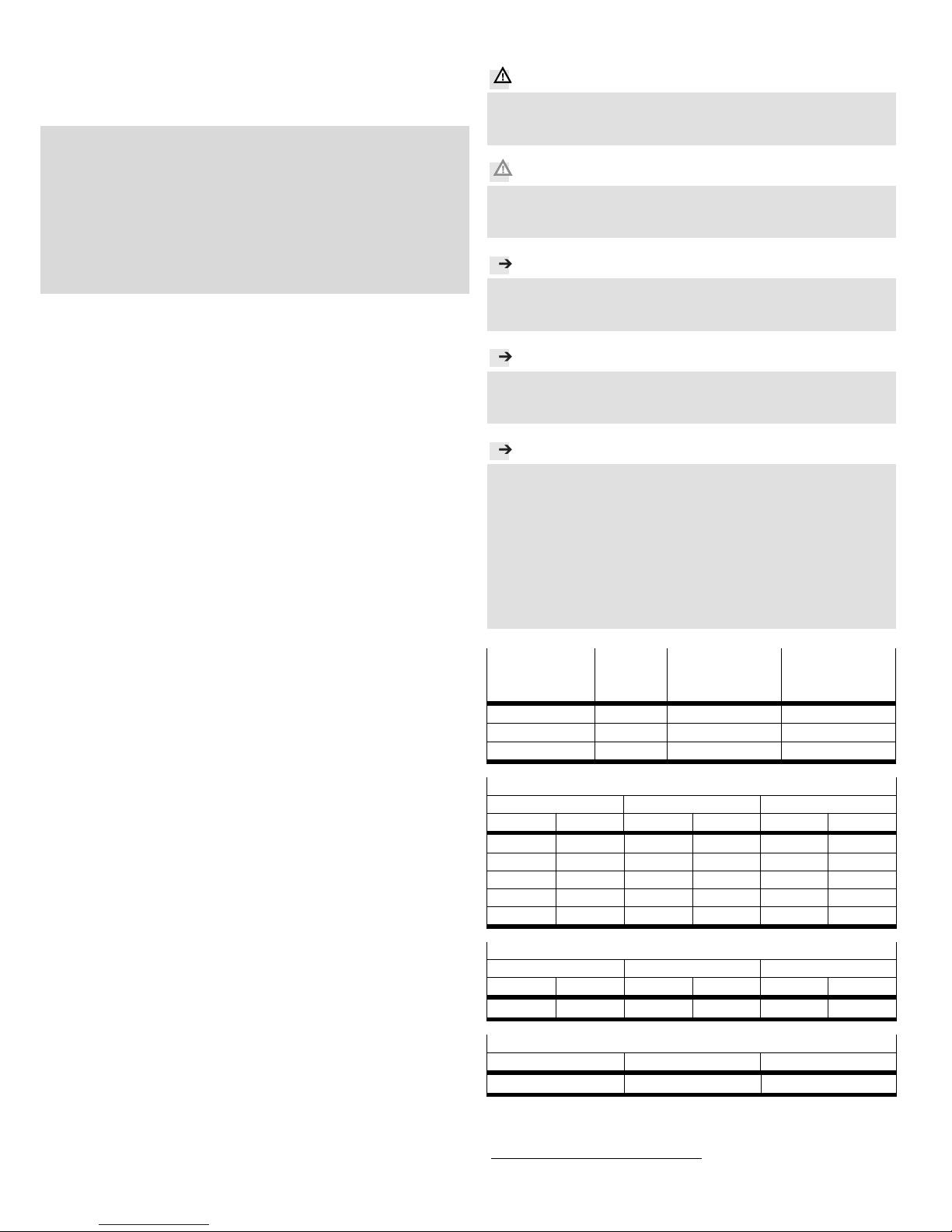
Resistance to vibration/ resistance to
shock
in accordance with
EN 60068
Wall H-rail
Vibration Part 2-6 SL21) SL1
Shock Part 2-27 SL2 SL1
Continuous shock Part 2-27 SL1 SL1
Vibration load
Frequency range [Hz] Acceleration [m/s
2
] Displacement [mm]
SL1 SL2 SL1 SL2 SL1 SL2
2 … 8 2 … 8 − − ±3.5 ±7
8 … 27 8 … 27 10 10 − −
27 … 58 27 … 60 − − ±0.15 ±0.7
58 … 160 60 … 160 20 50 − −
160 … 200 160 … 200 10 10 − −
Shock load
Acceleration [m/s
2
] Duration [ms] Shocks per direction
SL1 SL2 SL1 SL2 SL1 SL2
±150 ±300 11 11 5 5
Continuous shock load
Acceleration [m/s
2
] Duration [ms] Shocks per direction
±150 6 1000
1)
1)
SL1 = Severity level 1
SL2 = Severity level 2

2
2. Parts list
18375d_10
1 Terminal
CPX
(1x)
Wall mounting
18373d_2
Attachment for
CPX-modules (plastic):
2 Mounting
CPX-BG-RW-...
18373d_3
Mounting for
CPX-modules (metal):
3 Mounting bracket
CPX-M-BG-RW-...
4 Screw M3
(thread-cutting)
H-rail mounting
18373d_6
Not included in delivery:
5 H-rail
(EN 60715 - 35x7.5 or
35x15)
(1x)
18373d_7
Mounting
CPX-CPA-BG-NRH:
6 Screw
7 Clamping component
(3x)
(3x)
3. Intended use
Product Usage
CPX-terminal 1 Control of electric actuators.
Interrogation of the sensors.
Mounting 2/3 Additional wall mounting of the CPX-terminal 1.
1 3 4 2 5 7
6

3
4. Wall mounting
4a. Check positions of the mountings
Information
Counting direction of the mod-
ules:
– from end plate (U).
18373d_16
Information
Mountings are pre-assembled, dependent on the configuration.
Check positions of the pre-assembled mountings ( tables) and correct,
if required ( section 4b).
Mounting 2 with CPX-modules (plastic)
Number of modules Mounting between the modules
2/3 5/6 8/9
1 … 3 −
4 … 5 •
6 … 8 • •
9 … 10 • • •
Mounting 3 for CPX-modules (metal)
Number of modules Mounting to the modules
2 3 4 6 7
1 … 3 −
4 •
5 … 6 •
7 •
8 • •
9 … 10 • •
4b. Assemble mountings
Mounting 2 to CPX-modules (plastic)
18375d_4
Press mounting 2 inclined
into the modules (A).
Tilt mounting 2 until it
catches.
Assemble additional mount-
ing 2 opposite.
Mounting 3 to CPX-modules (metal)
Information
For CPX-modules (metal) without system supply, the mounting 3 can be assembled on both sides of the module.
18375d_14
Place mounting 3 aligned
on the module (B).
Tighten screws 4. If you
screw it in again, use the
threads already present.
Observe tightening torque.
2 2
A
3
B
1.5 Nm ± 10 %
4
U

4
4c. Overview of the fastening points
Note
Material damage due to incorrect assembly.
Select screws suitable for the installation situation.
CPX-terminal (plastic)
18375d_7
Mounting point Screw size Number
(C) M6 2x
(D) M4 1x every 2
(E) M6 2x
CPX-terminal (metal)
18375d_15
Mounting point Screw size Number
(C) M6 2x
(F) M6 1x every 3
(E) M6 2x
E
E
D
D
C
D
D
C
E
E
C
F F
C
2
3
5
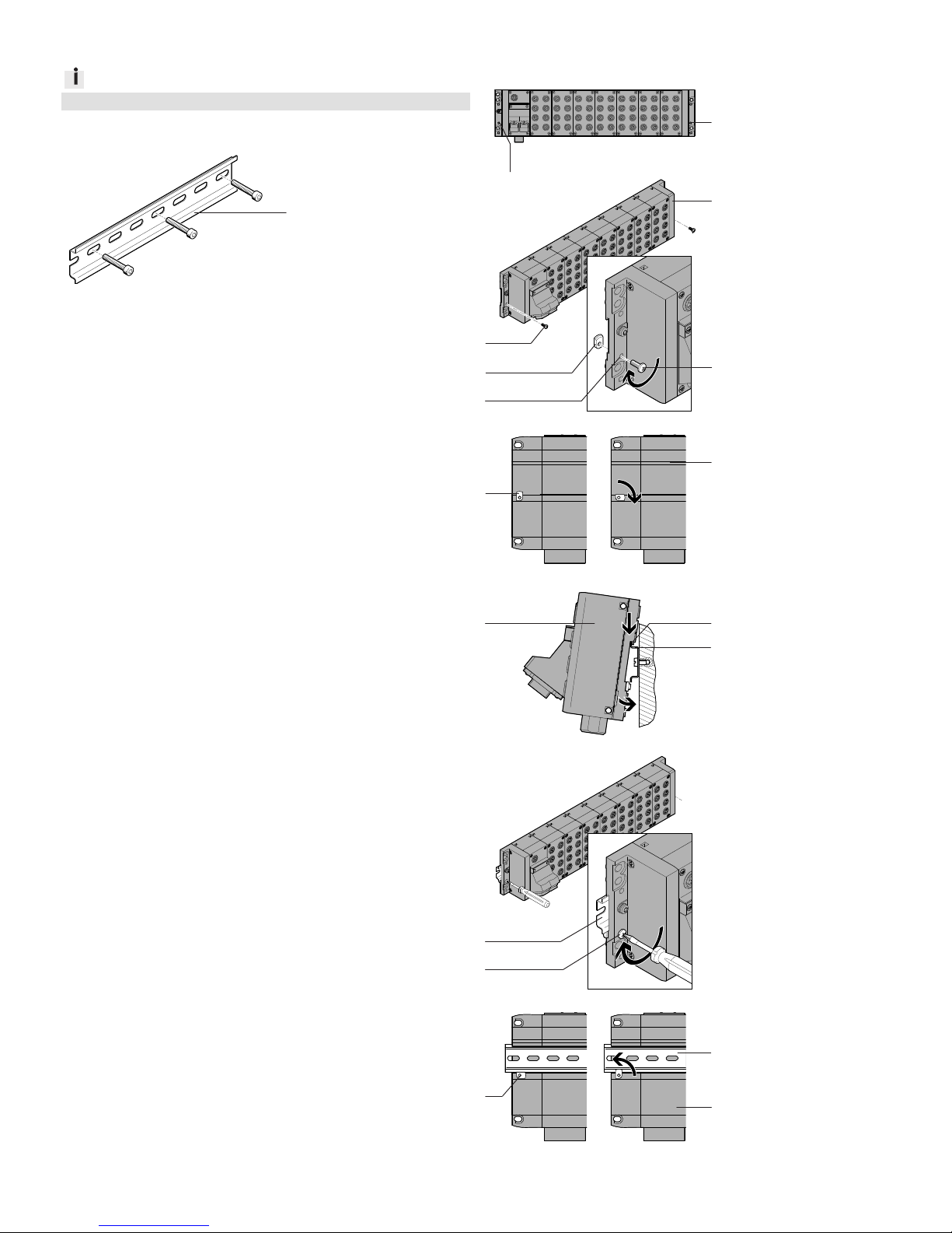
5. H-rail mounting
Information
A screw 6 and a clamping component 7 are left over.
5a. Mount H-rail
18373d_20
Mount H-rail 5 horizon-
tally.
5b. Mount CPX-terminal to H-rail
18375d_6
Remove pre-assembled
mountings 2/3.
18375d_9
On the reverse side of the
modules:
Place clamping compo-
nents 7 at the mounting
points (G).
Fix clamping components 7
with screws 6.
18373d_22
Align clamping compo-
nents 7 parallel to the
slot (H).
18373d_24
Hang CPX-terminal 1 onto
the H-rail 5 at the slot (H).
Swivel CPX-terminal 1 onto
the H-rail 5.
18375d_8
Tighten screws 6. Observe
the tightening torque.
18373d_23
Tightening the screws 6 turns
the clamping components 7
by 90°. CPX-terminal 1 is secured against tilting and slipping.
H
1
1 6
6
7
G
G
G
7
5 1 5
1.3 Nm ± 10 %
5
H
5
6
7
 Loading...