

Page 1
Compact performance
Description
Programming and
diagnosis
CP field bus node 6
Field bus protocol:
INTERBUS−S
typeCP−FB6−E
Description
165 206
en 0802g
[730 602]
Page 2

Page 3

Contents and general instructions
Original de. . . . . . . . . . . . . . . . . . . . . . . . . . . . . . . . . . . . . . .
Edition en 0802g. . . . . . . . .
. . . . . . . . . . . . . . . . . . . . . . . . .
Designation P.BE−CP−FB6−E−EN. . . . . . . . . . . . . . . . . . . . . . . .
no. 165 206. . . . . . . . . . . . . . . . . . . . . . . . . . . . . . . . .
Order
E (Festo AG&Co. KG, D73726 Esslingen,
Germany
2008)
Federal Republic of
Internet: http://www.festo.com
E−Mail: [email protected]
The copying, distribution and utilization of this document as
well as the communication of its contents to others without
expressed authorization is prohibited. Offenders will be held
liable for the payment of damages. All rights reserved, in
particular the right to carry out patent, utility model or
ornamental design registration.
Festo P.BE−CP−FB6−E−EN en 0802g
I
Page 4

Contents and general instructions
II
Festo P.BE−CP−FB6−E−EN en 0802g
Page 5

Contents and general instructions
Contents
Designated use V . . . . . . . . . . . . . . . . . . . . . . . . . . . . . . . . . . . . . . . . . . . . . . . . . . . . . . . .
Target group VI . . . . . . . . . . . . . . . . . . . . . . . . . . . . . . . . . . . . . . . . .
Service VI . . . . . . . . . . . . . . . . . . . . . . . . . . . . . . . .
Notes on the use of this manual VI . . . . . . . . . . . . .
Important user instructions VII . . . . . . . . . . . . . . . . .
. . . . . . . . . . . . . . . . . . . . . . . . . . . . . . .
. . . . . . . . . . . . . . . . . . . . . . . . . . . . . .
. . . . . . . . . . . . . . . . . . . . . . . . . . . . .
. . . . . . . . . . . . . . . . .
1. Installation 1−1 . . . . . . . . . . . . . . . . . . . . .
1.1 General instructions 1−3 . . . . . . . . . . . . . . . . . .
1.2 Setting the DIL switches 1−4 . . . . . . . . . . . . . . . . . . . .
1.3 Connecting the INTERBUS interface 1−6 . . . . . . . . . . . . . . . . . . . . . . . .
1.3.1 Floating structure 1−8 . . . . . . . . . . . . . . . . . . . . . . . . . . . . . . . . . . . . . . . . .
1.3.2 Non−floating structure 1−9 . . . . . . . . . . . . . . . . . . . . . . . . . . . . . . . . . . . . . . . . . .
1.4 Connection to the remote bus 1−10 . . . . . . . . . . . . . . . . . . . . . . . . . . . . . . . . . . . . .
1.4.1 Floating remote bus 1−10 . . . . .
1.4.2 Non−floating remote bus 1−12 . . . . . . .
1.5 Connection to the installation remote bus 1−15 . . . . . . . . . . .
1.5.1 Non−floating installation remote bus 1−15 . . . . . . . . . . . . . . . . . . . . . . . . . . . . . .
1.6 Connecting CP modules 1−17 . . . . . . . . . . . . . . . . . . . . . . . . . . . . . . . . . . . . . . . . . .
1.7 Connecting the power supply 1−18
2. Commissioning 2−1 . . . . . . . . . . . .
2.1 Preparing the CP system for operation on the INTERBUS 2−3 . . . . . .
2.1.1 Operating voltage 2−3 . . . . . . . . . . . . . . . . . . . . . . . . . . . . . . . . . . . . . . .
2.1.2 Saving the string assignment 2−3 . . . . . . . . . . . . . . . . . . . . . . . . . . . . . . . . . . . . .
2.2 Preparing the
2.2.1 Creating the configuration list 2−4 . . . . . . . . . . . . . . . . .
2.2.2 Bus configuration via the CMD software 2−5 . . . . . . . . . . . . . . . . . . . . . . . . .
2.2.3 Bus configuration without CMD software 2−14 . . . . . . . . . . . . . . . . . . . . . . . . . . . .
2.3 Commissioning the CP system on the INTERBUS 2−19 . . . . . .
2.4 Configuration 2−21 . . . . . . . . . . . . . . . . . . . . . . . . . . . . . . . . . .
2.4.1 Addressingthe inputs/outputs 2−21 . . . . . . . . . . . . . . . . . . . . . . . . . . . . . . . .
2.4.2 Manufacturer−specific addressing (byte swap) 2−23 . . . . . . . . . . . . . . . . . . . . . . .
INTERBUS interface module 2−4 . . . . . . . . . . . . . . . . . . . . . . . . . .
. . . . . . . . . . . . . . . . . . . . . . . . . . . . . . . . . . . . . . . .
. . . . . . . . . . . . . . . . . . . . . . . . . . . . . .
. . . . . . . . . . . . . . . . . . . . . . . . . . .
. . . . . . . . . . . . . . . . . . . . . .
. . . . . . . .
. . . . . .
.
. . . . . . . . . . . . . . . . . . . . . . . . . . . . . . . . . .
. . . . . . . . . . . . . . . .
. .
. . . . . . . . . . . . . . . . . . . . . . . . . . . . . . . . . . . .
. . . . . . . . .
. . . . . . . .
. . . . . . . . . . . . . . . . . . . .
. . . .
. . . . . . . . . . . . . . . .
. . . . . . . . . . . . . . . .
. . . .
. . . . . . . . . . . . . . . . . . . . . . . . . . . . . . . . . . . . .
Festo P.BE−CP−FB6−E−EN en 0802g
III
Page 6

Contents and general instructions
2.4.3 Process data assignment via the CMD software (byte swap) 2−26 . . . . . . . . . . . .
2.4.4 Other instructions 2−30 . . . . . . . . . . . . . . . . . . . . . . . . . . . .
. . . . . . . . . . . . . . . . . . .
3. Diagnosis 3−1 . . . . . . . . . . . . . . . . . . . . . . . . . . . . . .
3.1 LED displays on the bus node 3−3 . . . . . . . . . . . . . . . . . . . . . .
3.1.1 Normal operating status 3−5 . . . . . . . . . . . . . . . . . . . . . . . . . . . . . . . .
. . . . . . . . . . . . . . . . . . . . . . .
. . . . . . . . . . . . . . .
. . . . . . . . .
3.1.2 Diagnosis power supply POWER or POWER V 3−6 . . . . . . . . . . . . . . . . . . . . . . . .
3.1.3 Diagnostic bus LEDs 3−7 . . . . . . . .
3.2 Testing the valves 3−9 . . . . . . . . . .
3.3 Diagnosis via INTERBUS 3−11 . . . . . . . . . . .
3.3.1 Diagnostic status register 3−11 . . . . . . . . . . . . . . . . .
3.3.2 Periphery fault (PF) 3−12 . . . . . . . . . . . . . . . . . . . . . . . . .
3.4 Reaction to faults in the control system 3−13 . . . . . . . . . . . . . . . . . . . . . .
A. Technical appendix A−1 . . . . . . . . . . . . . . . . . . . . . . . . . . . . . . . . . . . . . . . . . .
. . . . . . . . . . . . . . . . . . . . . . . . . . . . . . . . . . . . .
. . . . . . . . . . . . . . . . . . . . . . . . . . . . . . . . . . . . .
. . . . . . . . . . . . . . . . . . . . . . . . . . . . . .
. . . . . . . . . . . . . . . . . . . . . . .
. . . . . . . . . . . . . . . . . . . . .
. . . . . . .
. . .
A.1 Technical specifications A−3 . . . . . . . . . . . . . . . . . . . . . . . . . . . . . . . . . . . . . . . . . .
A.2 Index A−5 . .
. . . . . . . . . . . . . . . . . . . . . . . . . . . . . . . . . . . . . . . . . . . . . . . . . . . . . . .
IV
Festo P.BE−CP−FB6−E−EN en 0802g
Page 7

Contents and general instructions
Designated use
The CP field bus node type CP−FB6−E described in this manual
has been designed exclusively for use as a slave on the
INTERBUS−S. CP modules from Festo can be connected to CP
field bus node CP−FB6−E. The CP node may only be used as
follows:
in accordance with designated use
in its original state
without any modifications by the user
in faultless technical condition.
If additional commercially−available components such as sen
sors and actuators are connected, the specifiedlimits for pres
sures, temperatures, electrical data, torques, etc. must not
be exceeded.
Festo P.BE−CP−FB6−E−EN en 0802g
Please observe the standards specified in the relevant
chapters and comply with technical regulations, as well as
with national
and local regulations.
V
Page 8

Contents and general instructions
Target group
This manual is intended exclusively for technicians trained in
control and automation technology, who have experience in
installing, commissioning, programming and diagnosing
INTERBUS−S slaves.
Service
Please consult your local Festo repair service if you have any
technical problems.
Notes on the use of this manual
This manual contains specific information on installing, com
missioning, programming and diagnosing CP field bus node
FB6 for INTERBUS−S.
Current GSD files can be found on the Festo Internet pages
under:
www.festo.com/fieldbus
You can obtain the GSD files and further configuration aids
with the CD ROM Utilities" from Festo:
type P.CD−VI−UTILITIES−2, part no. 533500
most up−to−date GSD files are always available via the
The
Internet.
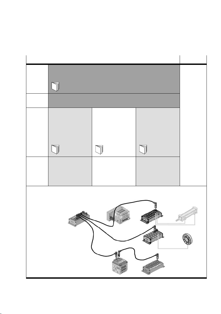
Information on further CP modules can be found in the man
ual for the relevant module. A summary is shown in fig. 0/1.
VI
Festo P.BE−CP−FB6−E−EN en 0802g
Page 9
Contents and general instructions
Important user instructions
Danger categories
This manual contains instructions on the possible dangers
which may occur if the product is not used correctly. These
instructions are marked (Warning, Caution, etc), printed on a
shaded background andmarked additionally with a picto
gram. A distinction is made between the following danger
warnings:
Warning
... This means that failure to observe this instruction may
result in serious personal injury or damage to property.
Caution
... This means that failure to observe this instruction may
result in personal injury or damage to property.
Festo P.BE−CP−FB6−E−EN en 0802g
Please note
... This means that failure to observe this instruction may
result in damage to property.
The following pictogram marks passages in the text which
describe activities with electrostatically sensitive compo
nents.
Electrostatically sensitive components may be damaged if
they are not handled correctly.
VII
Page 10

Contents and general instructions
Marking special information
The following pictograms mark passages in the text contain
ing special information.
Pictograms
Information:
Recommendations, tips and references to other information
sources.
Accessories:
Information on necessary or sensible accessories for the
Festo product.
Environment:
Information on environment−friendly use of Festo products.
VIII
Text markings
S The bullet indicates activites which may be carried out in
any order.
1. Figures denote
activities which must be carried out in the
numerical order specified.
Hyphens indicate general activities.
Festo P.BE−CP−FB6−E−EN en 0802g
Page 11
Contents and general instructions
bbbb
Manuals for the CP system Peripherals
Manual CP system, installation and commissioning"
Contents General, basic information on operating, fitting, installing and
Manual CP fieldbus node,
Contents Special information on
type: P.BE−CPSYS−...
commissioning of CP systems.
programming and
diagnosis"
type: P.BE−CP−FB...
or P.BE−VIFB...−10...
commissioning,
programming and
diagnosing related to
the node used
CPV valve terminal
pneumatics" or
CPAvalve terminal
pneumatics"
type: P.BE−CPV−...
or P.BE−CPA−...
Information on fitting,
installing and commis
sioning CPA or CPV
valve terminals
CP modules,
electronics"
type: P.BE−CPEA−...
Information on fitting,
installing and commis
sioning CP I/O
modules
Fig.0/1: CP system manuals
Festo P.BE−CP−FB6−E−EN en 0802g
IX
Page 12

Contents and general instructions
The following product−specific terms and abbreviations are
used in this manual:
Term/abbreviation
A digital output
Busy bit Enable bit, for analysing data exchange with the CP system
CP cable Special cable for coupling the various CP modules
CP connection Plug or socket on the CP modules which enables the modules to be
CP modules Common term for various modules which can be incorporated in a CP
CP system Complete system consisting of CP field bus node and P modules
E digital input
I/O modules Common term for the CP modules which provide digital inputs and
I/Os digital inputs and outputs
Node CP field bus node with/without field bus connection to which the I/O
Octet Number of address bytes assigned by the CP system
PLC/IPC Programmable logic controller/industrial PC
SAVE button: Save the current string assignment (connected I/Os);
Meaning
connected with the CP cable
system
outputs (CP input modules and CP output modules)
modules are connected
When the CP system is restarted, the last saved string assignment will
be compared with thecurrent string assignment. Deviations will be
indicated by flashing LEDs.
String Total number of I/O modules connected together on one CP connection
String assignment Total number of all the I/O modules connected via strings to a CP field
X
of the field bus node
bus node (0...3)
Festo P.BE−CP−FB6−E−EN en 0802g
Page 13

Installation
Chapter 1
1−1Festo P.BE−CP−FB6−E−EN en 0802g
Page 14

1. Installation
Contents
1. Installation 1−1 . . . . . . . . . . . . . . . . . . . . . . . . . . . . . . . . . . . . . . . . . . . . . . . . . . .
1.1 General instructions 1−3 . . . . . . . . . . . . . . . . . . . . . . . . . . . . . . . . . . . . . . . . . . . . .
1.2 Setting the
1.3 Connecting the INTERBUS interface 1−6 . . .
1.3.1 Floating structure 1−8 . . . . . . . . . . . . . . . . . . .
1.3.2 Non−floating structure 1−9 . . . . . . . . . . . . . . . . . . . . .
1.4 Connection to the remote bus 1−10 . . . . . . . . . . . . . . . . . . . . . . .
1.4.1 Floating remote bus 1−10 . . . . . . . . . . . . . . . . . . . . . . . . . . . . . . . . . .
1.4.2 Non−floating remote bus 1−12 . . . . . . . . . . . . . . . . . . . . . . . . . . . . . . . . . . . .
1.5 Connection to the installation remote bus 1−15 . . . . . . . . . . . . . . . . . . . . . . . . . . .
1.5.1 Non−floating installation remote bus 1−15 . . . . . . . . .
1.6 Connecting CP modules 1−17 . . . . . . . . . . . . . . . . . . . . . . . .
1.7 Connecting the power supply 1−18 . . . . . . . . . . . . . . . . . . . . . . . . . . . . .
DIL switches 1−4 . . . . . . . . . . . . . . . . . . . . . . . . . . . . . . . . . . . . . . . . . .
. . . . . . . . . . . . . . . . . . . . . . . . . . . . .
. . . . . . . . . . . . . . . . . . . . . . . . . . . .
. . . . . . . . . . . . . . . . . . . . . .
. . . . . . . . . . . . . .
. . . . . . . . . . .
. . . . .
. . . . . . . . . . . . . . . . . . . . . . .
. . . . . . . . . . . . . . . . . .
. . . . . . . .
1−2
Festo P.BE−CP−FB6−E−EN en 0802g
Page 15
1. Installation
1.1 General instructions
You thereby avoid:
uncontrolled movements of loose tubing.
unintentional movements of the connected actuators.
Warning
Before starting installation or maintenance work, switch off
the following:
S the compressed air supply
S the operating voltage and load voltage supply on the
field bus node (pins 1 and2)
S the load voltage supply to the CP output modules
Festo P.BE−CP−FB6−E−EN en 0802g
undefined
switching states of the electronic components.
Caution
The node of the CP system contains electrostatically
vulnerable components.
S Do not, therefore, touch any components.
S Please observe the regulations for dealing with electros
tatically vulnerable components.
In this way you will avoid irreparable damage to the elec
tronic components on the node.
General information on the installation of the CP assemblies
can
be found in the manual CP system".
1−3
Page 16
1. Installation
1.2 Setting the DIL switches
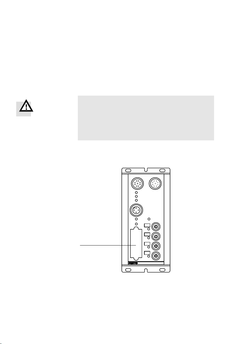
The DIL (dual in−line) switch is situated under the cover of the
field bus node.
Warning
S Before commissioning:
Set switch 4 to the position relevant to your controller
(see manufacturer−specific addressing).
S During operation:
Do not modify the setting of the DIL switch.
In this way you can avoid undesired reactions of the con
nected actuators.
1 DIL switch (under
cover)
1−4
RC
BA
RD
24VDC
POWER
SAVE
0
1
1
2
3
ERRORV
Fig.1/1: Position of the DIL switch
POWERV
Festo P.BE−CP−FB6−E−EN en 0802g
Page 17
1. Installation
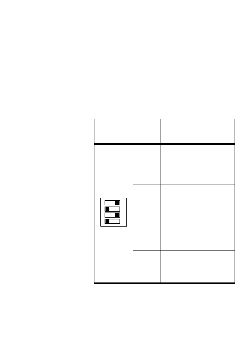
Dual inline switch Set the following functions on the DIL switch:
Switch the automatic valve test on/off
Select the common error messages/periphery messages
Manufacturer−specific addressing (byte swap) on the
INTERBUS
DIL switch
(factory
setting)
1
2
3
4
Switch Function description
1 Valve test
2 Select common error messages/
ON
3 ON: must be set at ON
4 Manufacturer−specific addressing
ON: CP system start without valve
test
OFF: CP system start with valve
test(operation see chapter
3.2)
periphery messages
OFF: all error messages are
transmitted
ON: only error messages 3, 4, 5
aretransmitted (see chapter
3.3.2)
OFF: reserved for internal test
purposes
(byte swap):
OFF: Siemens mode"
ON: Standard mode" (other
controllers)
Festo P.BE−CP−FB6−E−EN en 0802g
1−5
Page 18
1. Installation
1.3 Connecting the INTERBUS interface
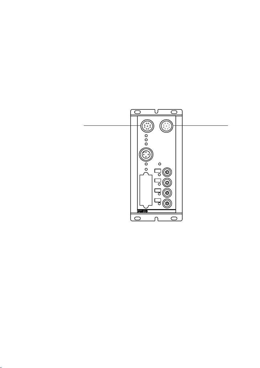
There are two connections on the field bus for the valve ter
minal. One of these connections is intended for the incoming
cable, the other for the continuing field bus cable.
1 INTERBUS inter
face incoming
2 INTERBUS inter
face continuing
12
RC
BA
RD
POWER
SAVE
24VDC
0
1
2
3
ERRORV
POWERV
Fig.1/2: INTERBUS interface
1−6
Festo P.BE−CP−FB6−E−EN en 0802g
Page 19

1. Installation
Different INTERBUS modules and therefore different screen
ing/shielding and connection methods must be used, de
pending on your application.
Screening/
Possible screening/shielding variants:
shieldingvariants
Floating structure:
(interference suppression via RC network or connection to
optical−fibre waveguide)
Non−floating structure:
(interference suppression via earthing on both sides)
Connection variants Possible connection variants:
Remote bus (floating/non−floating)
Remote bus with optical−fibre
Installation remote bus (non−floating)
Please observe the following differences between the remote
bus and the installation remote bus.
waveguide
Festo P.BE−CP−FB6−E−EN en 0802g
1−7
Page 20
1. Installation
2
1.3.1 Floating structure
Floating structures should be used preferably for parts of a
system which are situated at great distances from each other,
and where different earth potentials and interference are to
be expected as a result of equalizing currents or earthing
loops.
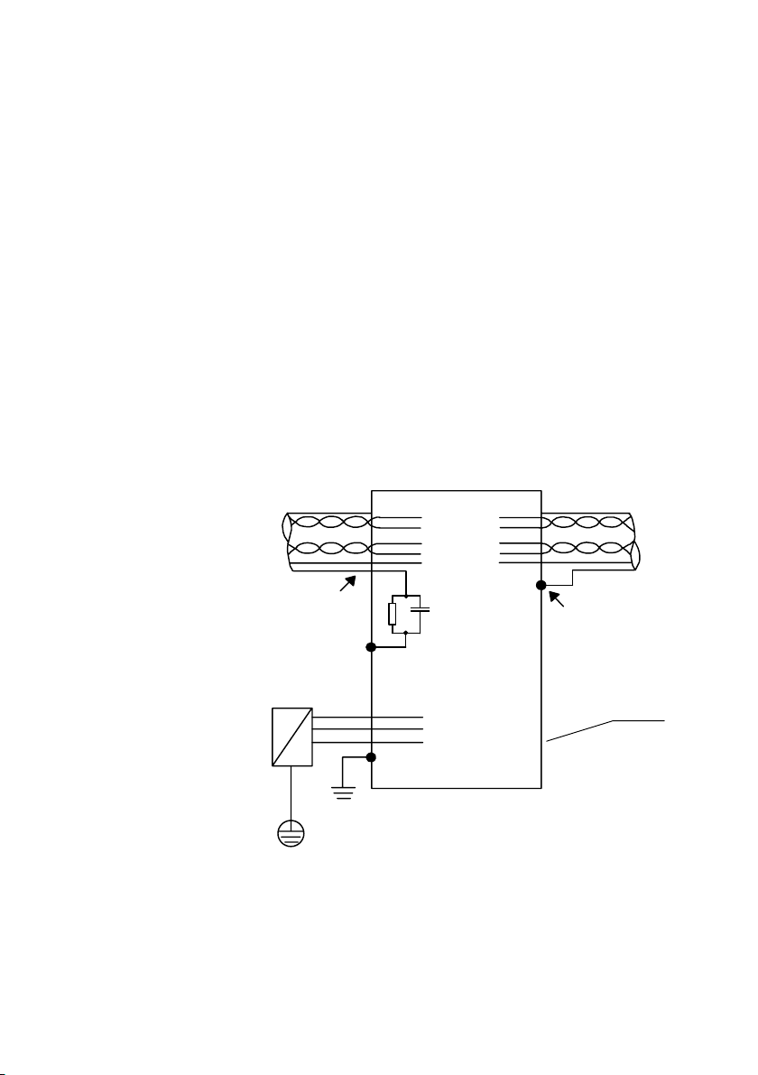
With floating structures, the electromagnetic interference
through the screening/shielding of the bus cable is
con
ducted to earth on one side via the RC network; on the other
side, however, it is earthed via the screening sleeve of a
metal plug. Any equalizing currents on the screening are
therefore prevented by the RC network.
1 INTERBUS
incoming
2 INTERBUS
continuing
3 Screening sleeve
(metal plug)
4 Fieldbus node
housing
5 Earthing via pin 4
6 No screening
sleeve, connect
screening to pin 6
7 RC network
Pin Pin
1
6
1
2
3
4
5
Pin
1
2
3
4
7
1
2
3
4
5
3
5
Fig.1/3: Circuit diagram of floating INTERBUS connection
4
1−8
Festo P.BE−CP−FB6−E−EN en 0802g
Page 21
1. Installation
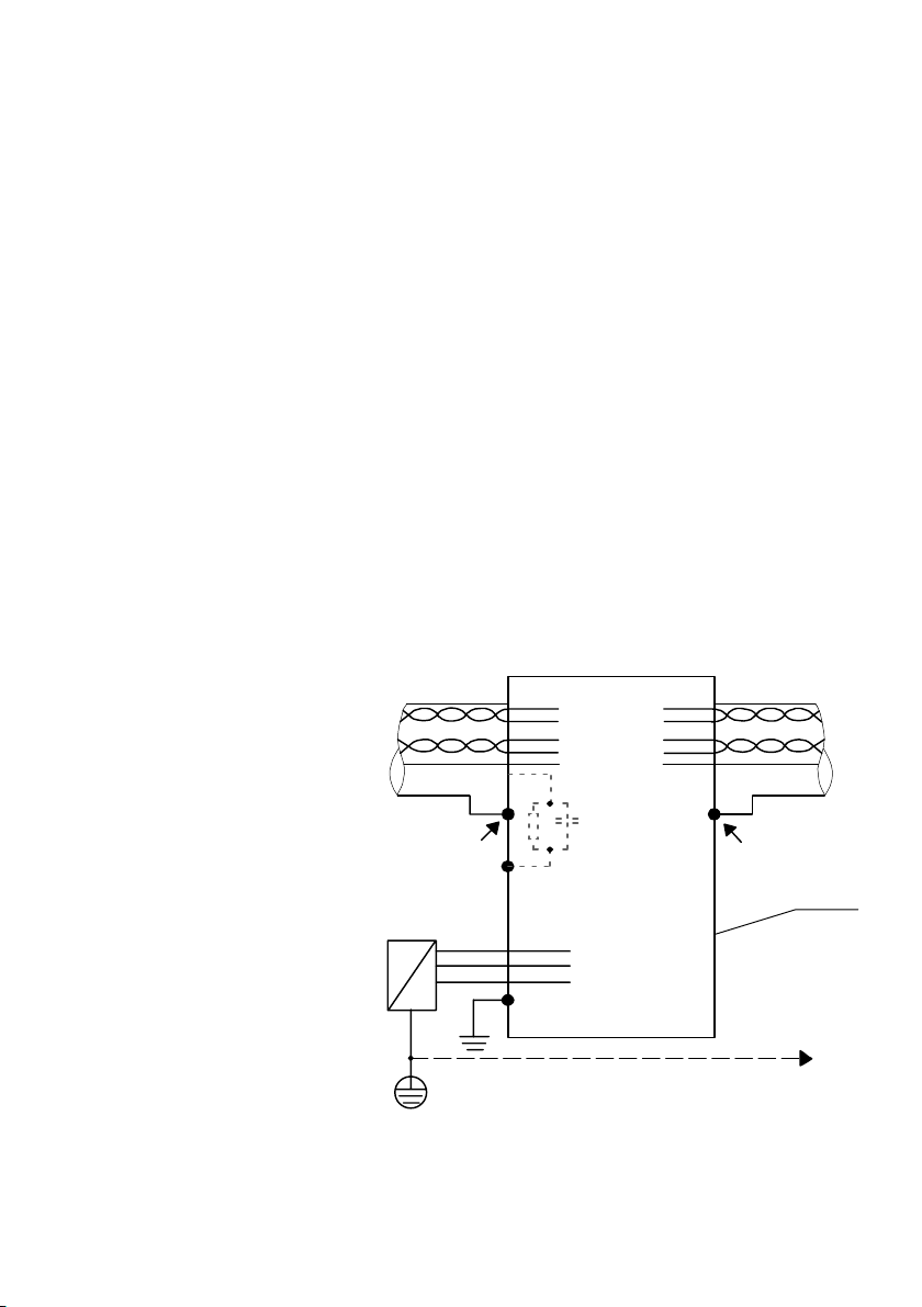
1.3.2 Non−floating structure
Non−floating screening designs should be used preferably in
the following cases:
in small systems with low interference
in bus environments with low−impedance, star−shaped
with locally earthed slaves in conjunction with potential
With non−floating structures, the electromagnetic interference
through the screening/shielding of the bus cable is earthed
on both sides via the screening
star−shaped low−impedance earthing or potential equalizing
cables are required for this purpose.
earthing
equalizing cables.
sleeve of a metal plug. A
1 INTERBUS incom
ing
2 INTERBUS con
tinuing
3 Screening sleeve
(metal plug)
4 Fieldbus node
housing
5 e.g. potential
equalization
6 Screening sleeve
(metal plug)
Festo P.BE−CP−FB6−E−EN en 0802g
Pin Pin
12
1
2
3
4
5
1
2
3
4
5
36
Pin
1
2
3
4
4
5
Fig.1/4: Circuit diagram of a non−floating INTERBUS
connection
1−9
Page 22

1. Installation
1.4 Connection to the remote bus
1.4.1 Floating remote bus
The field bus node is prepared for floating operation on the
remote bus. Check the valid standards and guidelines for
your application to see if a floating structure is suited to your
requirements. Further information on installing an INTERBUS
system can be found in the INTER BUS installation manual.
Obtainable from:
Phoenix Contact GmbH &
Postfach 1341
32 819 Blomberg, Germany
Article: IBS SYS INST UM
Order no. :27 54 28 6
Co.
1−10
Festo P.BE−CP−FB6−E−EN en 0802g
Page 23

1. Installation
Connecting to optical−fibre waveguide
Connection to the bus can also be made with a optical−fibre
waveguide. Contact connectors offer a ready−to−use data
transfer system ZYLIN RS485" for this purpose. This can be
connected to the valve terminal. The ZYLIN RS485 system is
self−supplying and consists of two pin−compatible 9−pin IP 67
round plugs, integrated optoelectronics and plastic
fibre waveguide.
Advantages:
large transmission band width
insensitive to electrical and magnetic interference
low weight
low space requirements
Further information, order forms and technical specifications
can be obtained from:
optical−
Festo P.BE−CP−FB6−E−EN en 0802g
Fa. Contact Connectors GmbH
Gewerbestrasse 30
70565 Stuttgart, Germany
Internet: Lappgroup.com
1−11
Page 24
1. Installation
1.4.2 Non−floating remote bus
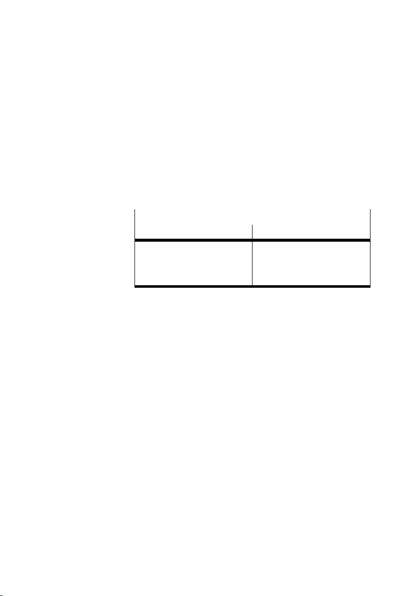
The plugs or sockets and cables listed below can be obtained
from the suppliers quoted. The plugs or sockets are suitable
only for the cables named here. You must order different
plugs if you wish to use cables with other outer diameters, as
the dimensions of the screening sleeve and the inner diam
eter of the cable must fit exactly.
Address of suppliers
Plug/socket Cable
CONINVERS GmbH
Daimlerstr. 13
D−71083 Herrenberg
Germany
Phoenix
Postfach 1341
D−32819 Blomberg
Germany
1−12
Festo P.BE−CP−FB6−E−EN en 0802g
Page 25
1. Installation
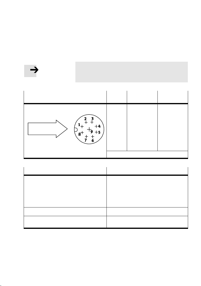
Connecting the incoming remote bus
Please note
Always connect the screening/shielding to both sides of
the sleeve.
Plugs/sockets to be connected (view of
Pin no. *)Designation Meaning
INTERBUS interface of the node)
1
Incoming
remote bus
Top view
2
3
4
5
Sleeve
*)
Do not connect pins not listed here
Plug selection Part no.
9−pin plug with socket insert, screened/shielded
with sleeve/housing.
Possible designs:
a) straight socket
b) angled socket
c) angled socket (locking)
a) RC−09 S 1 N 128 049
b) RC−09 S 1 N 12T 049
c) RC−09 S 3 N 12T 0Z0
Cable selection
LIYCY 3x2x0,25 mm
IBS RBC METER−T
2
28 06 28 6
DO
/DO
DI
/DI
Earth/GND
Screening
Data out
Data out invers
Data in
Data in invers
Reference cond.
Screening/
shielding
Festo P.BE−CP−FB6−E−EN en 0802g
1−13
Page 26
1. Installation
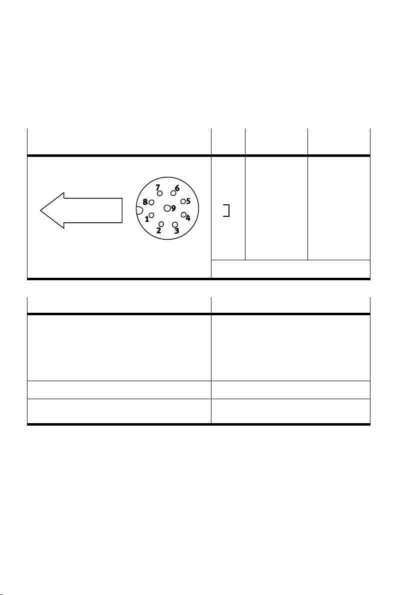
Connecting the continuing remote field bus
Plugs/sockets to be connected (view of
INTERBUS interface of the node)
Continuing re
mote field bus
Top view
Pin
*)
no.
1
2
3
4
5
9
Sleeve
*)
Do not connect pins not listed here
Pin selection Part no.
9−pin plug with pin insert, screened/shielded with
sleeve/housing.
Possible designs:
a) straight socket
b) angled socket
c) angled socket (locking)
a) RC−09 P 1 N 128 049
b) RC−09 P 1 N 12T 049
c) RC−09 P 3 N 12T 0Z0
Cable selection
LIYCY 3x2x0,25 mm2
IBS RBC METER−T
28 06 28 6
Designation Meaning
DO
/DO
DI
/DI
Earth/GND
RBST
Screening
Data out
Data out invers
Data in
Data in invers
Reference cond.
Bridge to pin 5
Screening/
shielding
1−14
Festo P.BE−CP−FB6−E−EN en 0802g
Page 27
1. Installation
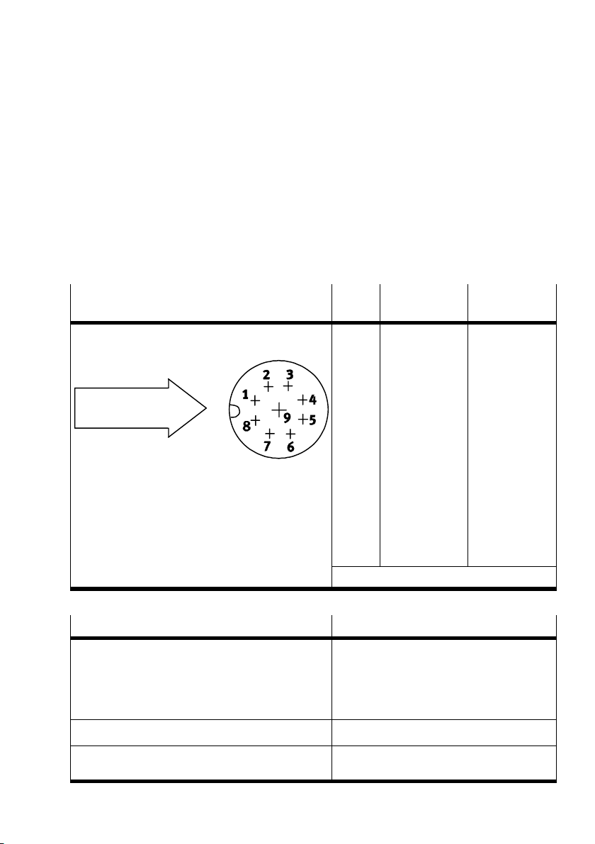
1.5 Connection to the installation remote bus
1.5.1 Non−floating installation remote bus
Connecting the incoming installation remote bus
Plugs/sockets to be connected (view of
INTERBUS interface of the node)
Incoming installation re
mote bus
Top view
Pin
*)
no.
1
2
3
4
5
6
7
8
Sleeve
*)
Do not connect pins not listed here
Plug selection Part no.
9−pin plug with socket insert, screened/shielded with
sleeve/housin g. Possible designs:
a) straight socket
b) angled socket
c) angled socket (locking)
a) RC−09 S 1 N 128 049
b) RC−09 S 1 N 12T 049
c) RC−09 S 3 N 12T 0Z0
Designation Meaning
DO
/DO
DI
/DI
Earth/GND
FE
+24V
+0V
Screening
Data out
Data out invers
Data in
Data in invers
Reference cond.
Functional
earthing of in
stallation re
mote bus
Supply to in
stallation re
mote bus
Supply to in
stallation re
mote bus
Screening/
shielding
Cable selection
LIYCY 3x2x0,25 mm2 + 3 x 1 mm
IBS INBC METER/S (resistant to welding)
Festo P.BE−CP−FB6−E−EN en 0802g
2
27 59 87 0
1−15
Page 28
1. Installation
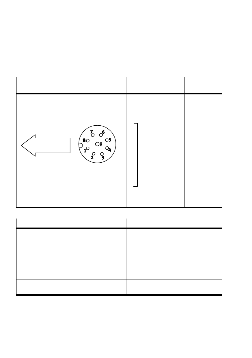
Connecting the continuing installation remote bus
Pin
*)
no.
1
2
3
4
5
6
Continuing installa
tion remote bus
Top view
7
8
9
Sleeve
Plug selection Part no.
9−pin plug with socket insert, screened/shielded
with sleeve/housing.
Possible designs:
a) straight socket
b) angled socket
c) angled socket (locking)
a) RC−09 P 1 N 128 049
b) RC−09 P 1 N 12T 049
c) RC−09 P 3 N 12T 0Z0
Designation Meaning
DO
/DO
DI
/DI
Earth/GND
FE
+24V
+0V
RBST
Screening
Data out
Data out invers
Data in
Data in invers
Reference cond.
Functional
earthing of in
stallation re
mote bus
Supply to in
stallation re
mote bus
Supply to in
stallation re
mote bus
Create bridge
to pin 5
Screening/
shielding
Cable selection
LIYCY 3x2x0,25 mm2 + 3 x 1 mm
IBS INBC METER/S (resistant to welding)
2
1−16
27 59 87 0
Festo P.BE−CP−FB6−E−EN en 0802g
Page 29
1. Installation
1.6 Connecting CP modules
Warning
S Use the special cable (type KVI−CP−1−...) from Festo for
connecting the CP modules to a string.
S The total cable length on one string must not exceed
10m.
You thereby avoid:
faults in data exchange between the node and the con
nected CP modules.
Information on this procedure can be found in the manual
CP system, installation and commissioning."
Festo P.BE−CP−FB6−E−EN en 0802g
1−17
Page 30
1. Installation
1.7 Connecting the power supply
Warning
S Use only PELV circuits as per IEC/DIN EN 60204−1 (Pro
tective Extra−Low Voltage, PELV) for the electrical supply.
Consider also the general requirements for PELV circuits
in accordance with IEC/DIN EN 60204−1.
S Use power supplies which guarantee reliable electrical
isolation of the operating voltage as per IEC/DIN EN
60204−1.
By the use of
PELV circuits, protection against electric shock
(protection against direct and indirect contact) is guaranteed
in accordance with IEC/EN 60204−1 (Electrical equipment for
machines, General requirements).
Information on this procedure as well as the connecting
cables and current consumption can be found in the manual
CP system, installation and commissioning."
1−18
Festo P.BE−CP−FB6−E−EN en 0802g
Page 31

Commissioning
Chapter 2
2−1Festo P.BE−CP−FB6−E−EN en 0802g
Page 32

2. Commissioning
Contents
2. Commissioning 2−1 . . . . . . . . . . . . . . . . . . . . . . . . . . . . . . . . . . . . . . . . . . . . . . . .
2.1 Preparing the
2.1.1 Operating voltage 2−3 . . . . . . . . . . . . . . . . . . . . . . . . . .
2.1.2 Saving the string assignment 2−3 . . . . . . . . . . . . . . . . . . . . . . . . . .
2.2 Preparing the INTERBUS interface module 2−4 . . . . . . . . . . . . . . . . . . . . . . . . . .
2.2.1 Creating the configuration list 2−4 . . . .
2.2.2 Bus configuration via the CMD software 2−5 . . . . . . . . . . . .
2.2.3 Bus configuration without CMD software 2−14 . . . . . . . . . . . . . . . . . . . . . . . . . . . .
2.3 Commissioning the CP system on the INTERBUS 2−19 . . . . . . . . . . . . . . . . . . . . . .
2.4 Configuration 2−21 . . . . . . . . . . . . . . . . . . . . .
2.4.1 Addressingthe inputs/outputs 2−21 . . . . . . . . . . . . . . . . . . .
2.4.2 Manufacturer−specific addressing (byte swap) 2−23 . . . . . . . . . . . . . . . . . . . . . . .
2.4.3 Process data assignment via the CMD software
2.4.4 Other instructions 2−30 . . . . . . . . . . . . . . . . . . . . . . . . . . . . . . . . . .
CP system for operation on the INTERBUS 2−3 . . . . . . . . . . . . . . .
. . . . . . . . . . . . . . . . . . . . .
. . . . . . . . . . .
. . . . . . . . . . . . . . . . . . . . . . . . . . . . . . . . .
. . . . . . . . . . . . . . . . .
. . . . . . . . . . . . . . . . . . . . . . . . . . . . .
. . . . . . . . . . . . . . . . .
(byte swap) 2−26 . . . . . . . . . . . .
. . . . . . . . . . . . .
2−2
Festo P.BE−CP−FB6−E−EN en 0802g
Page 33
2. Commissioning
2.1 Preparing the CP system for operation on the INTERBUS
2.1.1 Operating voltage
Please note
S The CP fieldbus node must have a separate operating
voltage supply.
The operating voltage for the remote bus/installation
remote bus is not used by the CP system. This voltage is
looped through in order to supply further INTER BUS
slaves.
2.1.2 Saving the string assignment
Festo P.BE−CP−FB6−E−EN en 0802g
Please note
Before commissioning the CP system, you must first pre
pare the CP system (see CP System" manual).
Before commissioning the CP system on the INTERBUS, pro
ceed as follows:
1. Connect the operating voltage for the node (see
CPsystem" manual).
2. Connect the CP modules.
3. Switch on the operating voltage.
4. Save the string assignment by
5. Switch off the operating voltage for the node.
pressing the SAVE button.
2−3
Page 34

2. Commissioning
2.2 Preparing the INTERBUS interface module
2.2.1 Creating the configuration list
Configuration list Before commissioning or programming you must create a
configuration list of all connected field bus stations. On the
basis of this list, you can:
S Make a comparison between the NOMINAL and ACTUAL
configurations, in order to detect any addressing errors
S Access these specifications during a syntax check of a
program, in order
Configuration of the CP system requires a very accurate pro
cedure, as different configuration specifications may be re
quired for each system due to the modular structure. Please
also observe the specifications in subsequent sections.
to avoid addressing errors.
2−4
Festo P.BE−CP−FB6−E−EN en 0802g
Page 35
2. Commissioning
2.2.2 Bus configuration via the CMD software
This chapter describes as an example the main steps which
you will require in the CMD software, in order to insert a Festo
CP system in your project. A general and comprehensive de
scription can be found in the relevant manual for the CMD
software. It is assumed here that the user is
with the information in the CMD manual.
Please note
S The software packages are subjected to modifications
which are not taken into account in this manual.
The examples of screen displays used here are taken from
the CMD software version 4.
Further and current information can be found in the man
ual for your CMD software.
already familiar
Festo P.BE−CP−FB6−E−EN en 0802g
2−5
Page 36
2. Commissioning
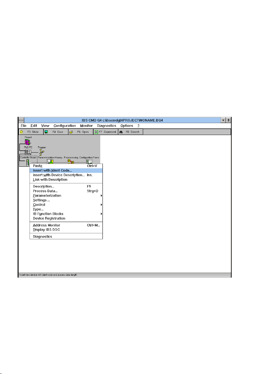
Inserting with the Ident−code
Proceed as follows:
S Open the dialogue window of the INTERBUS module.
S Select the option Inserting with the Ident−code.. .".
Fig.2/1: Inserting bus slaves with the Ident−code
2−6
Festo P.BE−CP−FB6−E−EN en 0802g
Page 37
2. Commissioning
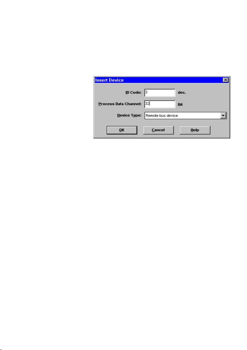
The following dialogue window will then appear:
Fig.2/2: Dialogue window Insert Device"
Enter the following in the dialogue fields:
S ID Code
Always enter Ident−code 3 for a CP system (with inputs
and outputs).
Festo P.BE−CP−FB6−E−EN en 0802g
2−7
Page 38
2. Commissioning
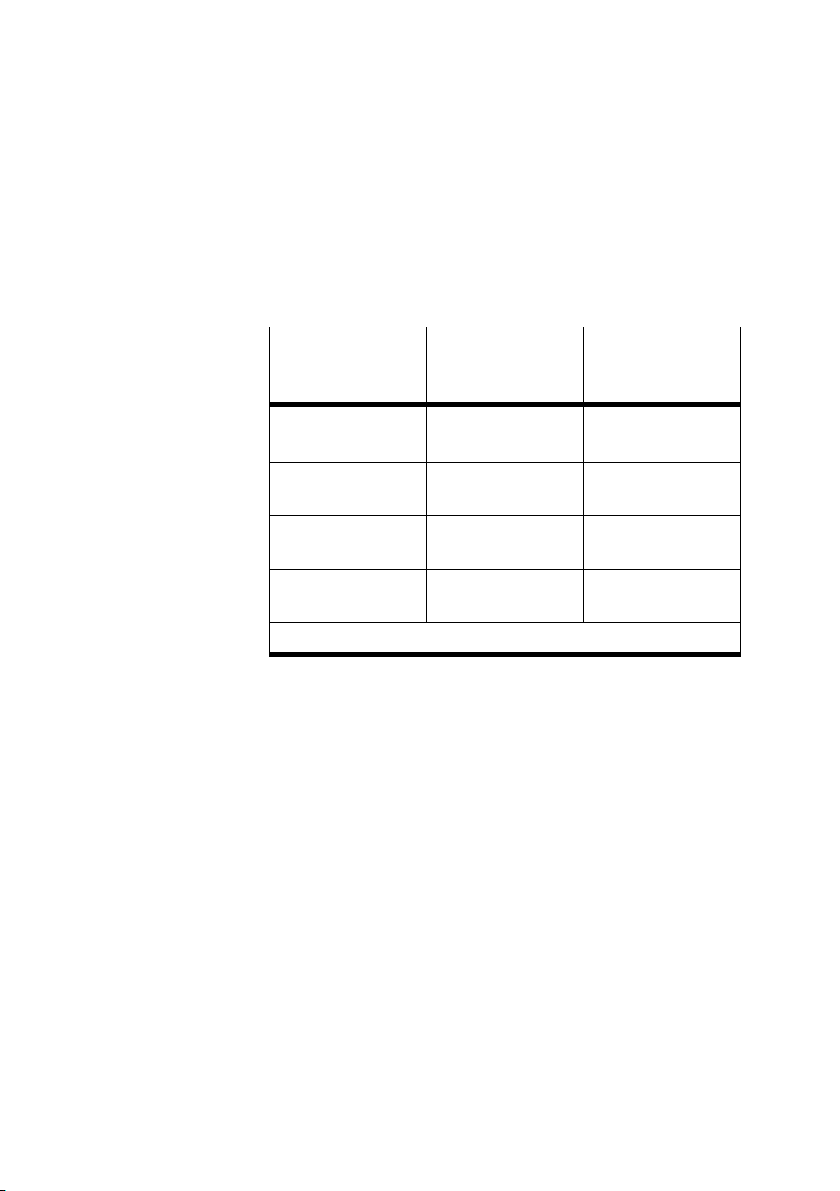
S Process Data Channel
Enter here the number of inputs and/or outputs in your
CP system. The last used string is decisive here (see
CPsystem manual).
CP system last
used string
Equipment on CP
system (assigned
Process data
channel bits
address range)
0 Up to 16 inputs/out
1 Up to 32 inputs/out
2 Up to 48 inputs/out
3 Up to 64 inputs/out
1) Valves and/or electrical outputs
puts
puts
puts
puts
1)
1)
1)
1)
16
32
48
64
S Device Type:
The default entry Remote bus device" can be entered.
S Save these entries with OK.
2−8
Festo P.BE−CP−FB6−E−EN en 0802g
Page 39
2. Commissioning
Insert Device Description
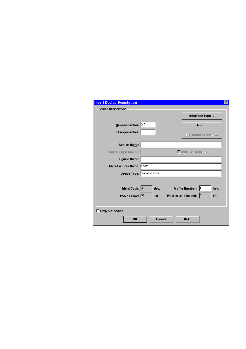
In the dialogue window below you can describe the slave and
enter information about the valve terminal, e.g. the name of
the station and a picture of the slave.
Festo P.BE−CP−FB6−E−EN en 0802g
Fig.2/3: Dialogue window Insert Device Description"
2−9
Page 40

2. Commissioning
Possible entries:
S Profile Number
The Festo CP system complies with the INTERBUS I/O
profile 12
. Enter this value in the box Profile Number."
H
S Interface Type
The default entry Interface Universal" can be transferred.
Alternatively you can select the types Remote bus or In
stallation remote bus.
S Icon
Open the dialogue window Icon ...,", if you wish to use
specific icons for the Festo CP system.
2−10
Festo P.BE−CP−FB6−E−EN en 0802g
Page 41
2. Commissioning
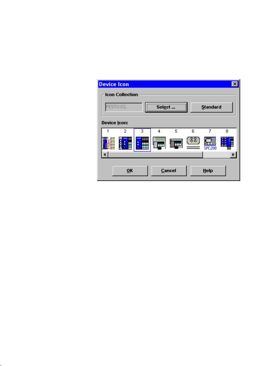
The following dialogue window will then appear:
Fig.2/4: Dialogue window Device Icon" for selecting an
icon
Festo P.BE−CP−FB6−E−EN en 0802g
Proceed as follows:
S Use the box Select ... " to select the file Festo.ICL.
S Mark the icon which corresponds to your CP system.
S Transfer the icon with OK.
2−11
Page 42
2. Commissioning
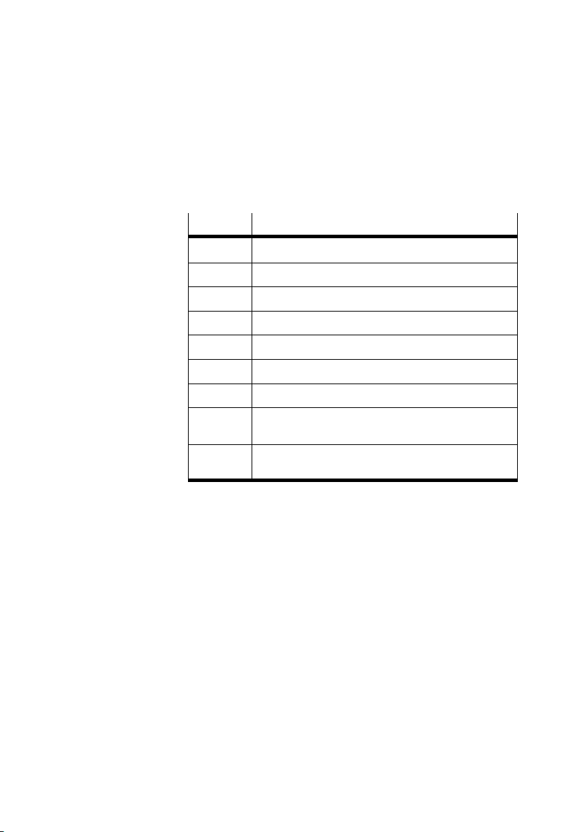
The icons are numbered. The following table shows the rela
tionship between the number of the icon and the valve ter
minal type.
Icon no.
1 Type 10 (CP system)
2 Types 03−05 with inputs and outputs
3 Types 03−05 only with valves and/or outputs
4 Type 02 with inputs and outputs
5 Type 02 only with valves
6 Type 10 with INTERBUS−Loop
7 SPC200 positioning system
8 Valve terminal type 03 with INTERBUS−LWL Rugged−
9 Valve terminal type 03 only with outputs, with INTER
Valve terminal type
Line
BUS−LWL Rugged−Line
2−12
Festo P.BE−CP−FB6−E−EN en 0802g
Page 43
2. Commissioning
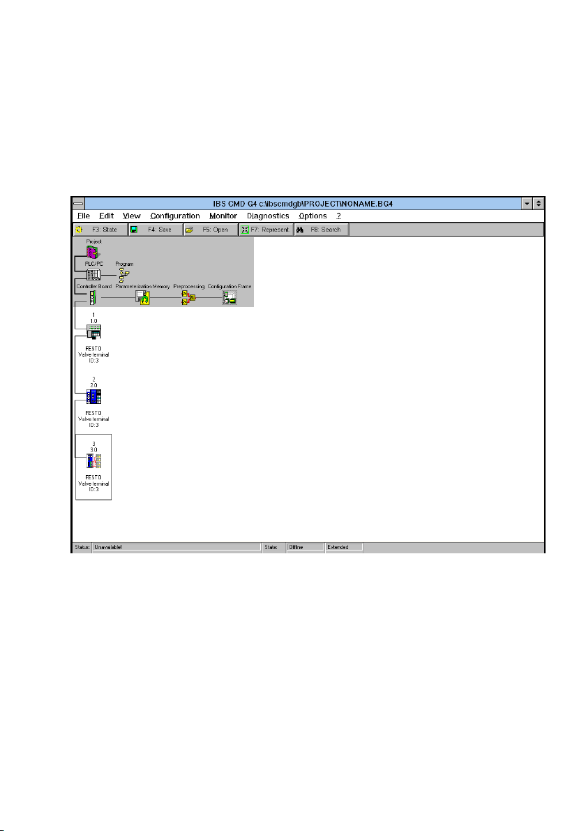
When all the entries have been completed, the CP system will
be integrated into your bus structure as follows (example):
Fig.2/5: Example inserted CP system
Festo P.BE−CP−FB6−E−EN en 0802g
2−13
Page 44
2. Commissioning
2.2.3 Bus configuration without CMD software
The CP system supports the following addressing and pro
gramming variants, depending on the module you are using:
logical addressing
physical addressing
Logical addressing
Please note
S ID CODE
Always configure a CP system (with inputs and out
1)
puts
) with Ident code 3.
1) Valve coils and/or electrical outputs
One or more configuration lists have been created in the PLC
or in the INTERBUS module for logical addressing. These lists
contain at least the following entries:
2−14
the ID codes of all slaves
the logical addresses of all slaves
the number of inputs
the number of outputs
Festo P.BE−CP−FB6−E−EN en 0802g
Page 45
2. Commissioning
Ascertaing the logical
address
These specifications must be known or ascertained for each
bus slave. In order to do this, proceed in the case of the CP
system as follows:
S Ascertain the address range reserved by the CP system.
The last used string is decisive here (see CP system"
manual).
S Ascertain the required number
of bits for the process data
channel according to the following table.
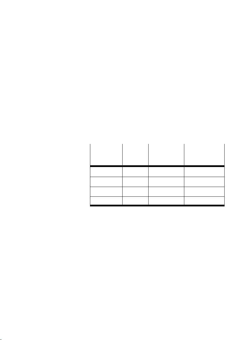
Ascertaining the ID code and process data channel bits
Last used
string on
ID code Process data
channel bits
Reserved
address range
CPsystem
0 3 16 16 inputs/outputs
1 3 32 32 inputs/outputs
2 3 48 48 inputs/outputs
3 3 64 64 inputs/outputs
Festo P.BE−CP−FB6−E−EN en 0802g
2−15
Page 46
2. Commissioning
S Assign each slave with a logical INPUT and OUTPUT ad
dress.
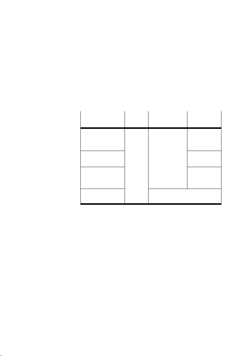
Example:
configuration list with ID code and process data channel
bits:
String assign
ment CP system
String 0:
16 outputs and
16 electrical inputs
String 1:
reserved
String 2:
16 outputs and
16 electrical inputs
String 3:
non−reserved
ID code Process data
channel bits
3 48 O 20.0 ... 21.7
Address range can be used for
other bus slaves
I/O address
(IN/OUT)
I 20.0 ... 21.7
O 22.0 ... 23.7
I 22.0 ... 23.7
O 24.0 ... 25.7
I 24.0 ... 25.7
2−16
Festo P.BE−CP−FB6−E−EN en 0802g
Page 47
2. Commissioning
Physical addressing
Please note
S Use the logical addressing or the bus configuration via
the CMD software, if your INTERBUS module permits
this.
You can thereby avoid shifting input and output addresses
during any later extensions.
The first bus slave is addressed with the basis address of the
INTERBUS module. You can obtain the address of the
bus slave by adding to the basis address the appropriate
number of bits in the process data channel of all the slaves.
This process must be carried out separately for the inputs
and the outputs.
Please note
The number of inputs on a CP system may differ from the
number of outputs.
next
Festo P.BE−CP−FB6−E−EN en 0802g
1. Ascertain the address range reserved by the CP system.
The last used string is decisive here (see CP system"
manual).
2. Ascertain the required number of bits for the process data
channel according to the following table.
3. Calculate the
physical addresses of all the slaves (see
following example).
2−17
Page 48
2. Commissioning
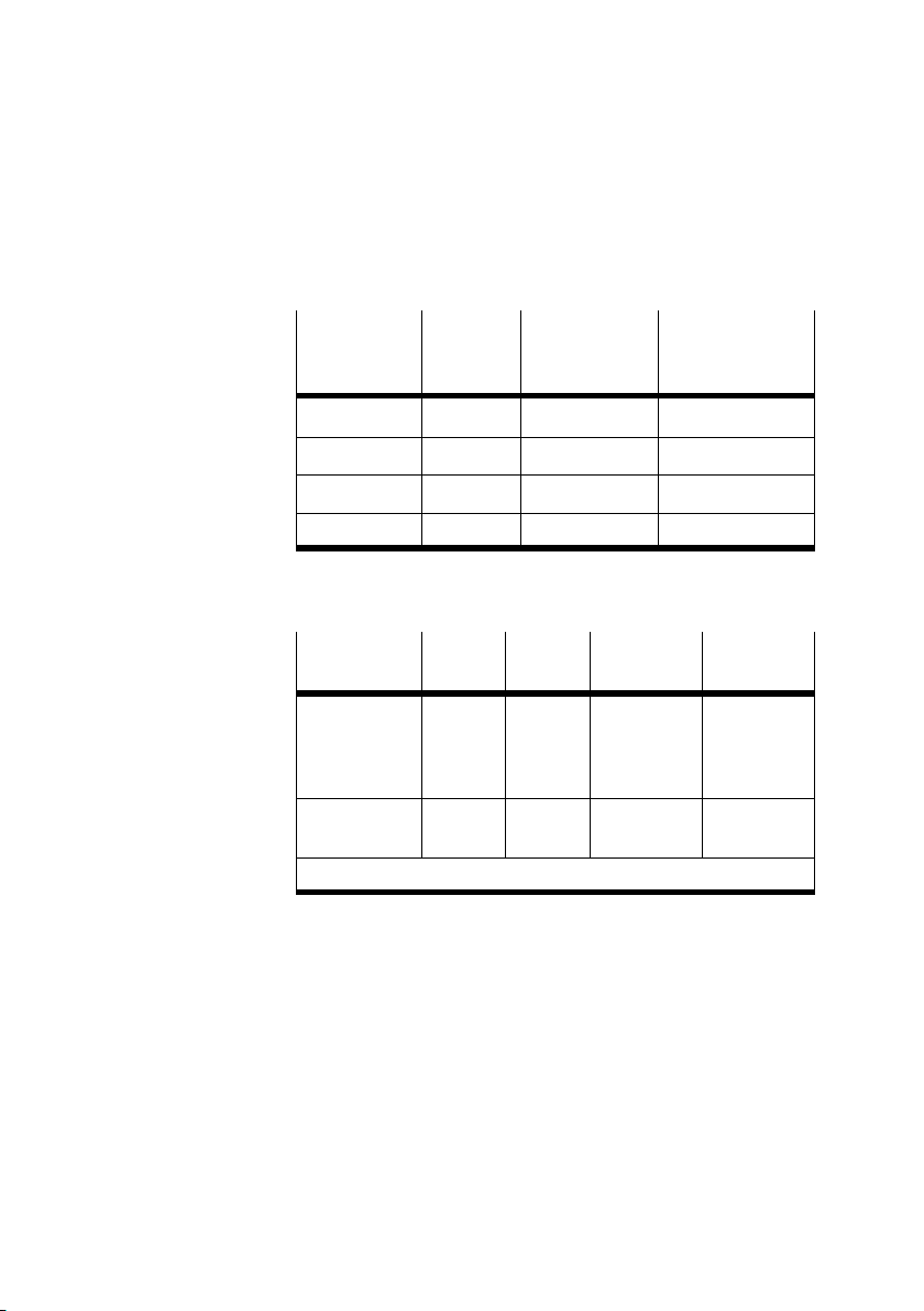
Ascertaining the number of bits for the process data
channel per CP system
Last used
string of
ID code Process data
channel bits
Reserved
address range
CPsystem
0 3 16 16 inputs/outputs
1 3 32 32 inputs/outputs
2 3 48 48 inputs/outputs
3 3 64 64 inputs/outputs
Example Calculating the physical addresses
Process data
channel bits
(assigned
strings)
Physical word
address
BA = Basic address
1st. CP
system
16
(1)
BA BA + 16 BA + 16 + 48 BA + 16 + 48
2nd. CP
system
48
(3)
3rd. CP
system
64
(4)
4th. CP
system
32
(2)
+ 64
2−18
Festo P.BE−CP−FB6−E−EN en 0802g
Page 49

2. Commissioning
2.3 Commissioning the CP system on the INTERBUS
Please note
The switching−on instructions in the manual for the INTER
BUS module must also be observed.
Proceed as follows:
1. Connect the INTERBUS cables to the field bus node.
2. Switch on the operating voltages:
S for all remote bus/installation remote bus slaves,
S for the CP system.
3. Switch on the operating voltage for the master module.
Configuration run When you switch your controller on, it will automatically carry
out a comparison between the NOMINAL and ACTUAL con
figurations. For this configuration run it is important that:
Festo P.BE−CP−FB6−E−EN en 0802g
the specifications for the NOMI NAL configuration are com
plete and correct.
the power supplies to the PLC and to the field bus slaves
are switched
on either simultaneously or in the sequence
specified above.
The bus is not able to operate until all the bus slaves are
switched on.
2−19
Page 50

2. Commissioning
If the message PF periphery fault" occurs when the operat
ing voltages are switched on (pin 1 of the field bus node), the
load voltage is probably not switched on at pin 2. This will
lead to an error message because of the factory setting of the
DIL switch.
Recommendation.
If the safety concept
of your machine/system permits, com
mission the CP system with both voltages (pins 1 and 2), but
without compressed air.
In this way, you have the possibility of testing without the risk
of undesired reactions.
2−20
Festo P.BE−CP−FB6−E−EN en 0802g
Page 51
2. Commissioning
2.4 Configuration
2.4.1 Addressingthe inputs/outputs
Further specifications on addressing and programming can
be found in the manuals for your controller and the INTER
BUS module.
Please note
A CP valve location occupies two addresses.
The following applies:
lower−value address: pilot solenoid 14
higher−value address: pilot solenoid 12
The address assignment (process data assignment) of the CP
inputs/outputs and of the CP valve terminal on the INTERBUS
or compatible bus systems depends principally on the INTER
BUS module and your
controller.
Festo P.BE−CP−FB6−E−EN en 0802g
Caution
There are different address assignments on the INTERBUS.
This is due to the assignment of the processing data within
the INTERBUS module and not within the Festo CP system.
S Make sure that DIL switch element 4 is set correctly for
your addressing (see chapter 1).
S Observe the position of the high and
n/n+1) when assigning the addresses for the CP system,
as the position of these bytes may be swapped in the
case of some control systems.
You thereby avoid errors in addressing the inputs/outputs.
low bytes (byte
2−21
Page 52

2. Commissioning
The following examples show the different address assign
ments and the position of the low byte (n) and the high byte
(n+1). A distinction is made here between the:
Siemens mode and the
Standard mode
Example:
In the Siemens mode the lower value output byte (byte n)
is mapped on valve coils 0−7 of the
valve terminal, byte
n+1 is mapped on coils (8−15), etc.
In the Standard mode the lower value output byte (byte n)
is mapped on valve coils 8−15 of the valve terminal, byte
n+1 is mapped on coils 0−7.
In the following chapters you will find instructions on modify
ing the position of
the low bytes and high bytes (Byte
swap").
2−22
with hardware by means of the DIL switch setting (chapter
2.4.2, Manufacturer−specific addressing by means of the
DIL switch")
with software in a user−friendly manner by re−addressing
with the CMD software (chapter 2.4.3 Process data as
signment by means of CMD software"). The DIL switch
setting remains
unchanged (factory setting).
Festo P.BE−CP−FB6−E−EN en 0802g
Page 53
2. Commissioning
2.4.2 Manufacturer−specific addressing (byte swap)
Please note
S The address assignment specified by the manufacturer
for your controller/INTERBUS module must also be ob
served, irrespective of the following example.
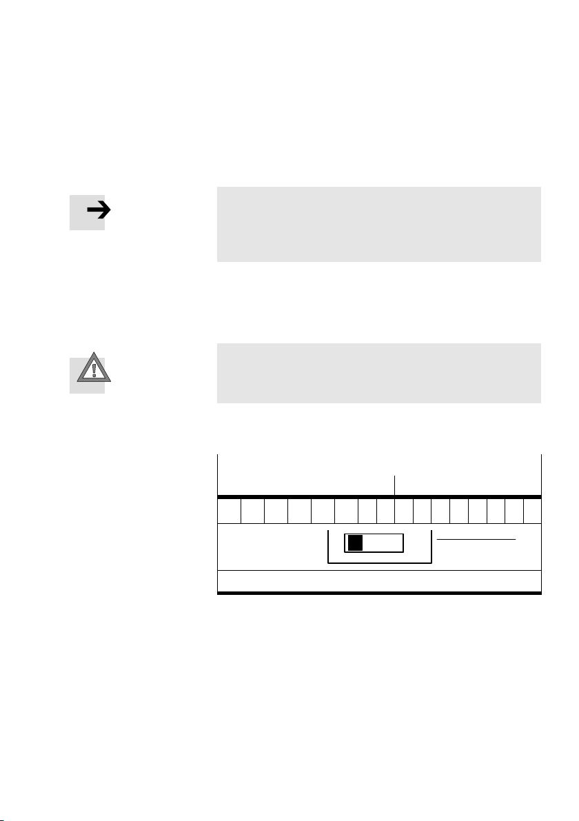
The setting of DIL switch element 4 determines how the pro
cessing data word is composed. The factory setting is OFF =
Siemens mode.
Caution
S When replacing a CP field bus node CP−FB6−E, make sure
that the DIL switch is correctly set.
You thereby avoid errors in addressing the inputs/outputs.
Festo P.BE−CP−FB6−E−EN en 0802g
Siemens mode: Structure of process data word
High byte (byte n+1) Low byte (byte n)
15 14 13 12 11 10 9 8 7 6 5 4 3 2 1 0
4
1
1 DIL switch element 4: OFF = Siemens mode
Fig.2/6: Structure of the process data word in Siemens
mode
2−23
Page 54
2. Commissioning
1
A0 ... A63
E0 ... E63
2
A0 ... A15
A16 ... A23 (A24 ... A31)
A32 ... A39 (A40 ... A47)
A48 ... A55 (A56 ... A63)
2
E0 ... E15
E16 ... E31
E32 ... E47
E48 ... E63
E = Input; A = Output; ( ) = Reserved address range; assigned but not used
1 Address range occupied by the CP sys
2 Address range used by the module
tem
Fig.2/7: Address assignment of the outputs and inputs
2−24
Festo P.BE−CP−FB6−E−EN en 0802g
Page 55
2. Commissioning
If you use the controllers of another manufacturer as master
on the INTERBUS, you can set the process data word to suit
your addressing. To do this, set DIL switch element 4 to ON =
Standard mode (controller manufacturer other than Siemens).
The high byte (byte n+1) and the low byte (byte n)
will then
be swapped.
Caution
S When replacing a CP field bus node CP−FB6−E, make sure
that the DIL switch is correctly set.
You thereby avoid errors in addressing the inputs/outputs.
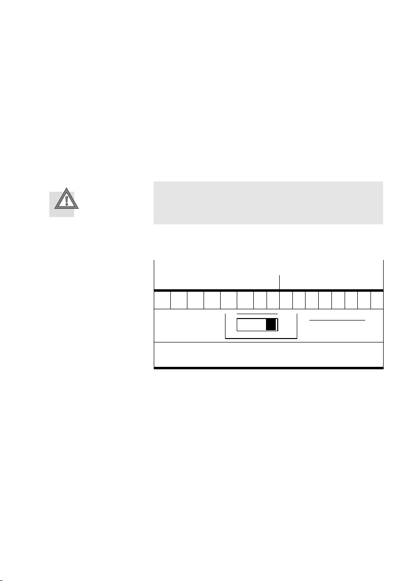
Standard mode: structure of process data word
Low byte (byte n) High byte (byte n+1)
15 14 13 12 11 10 9 8 7 6 5 4 3 2 1 0
Festo P.BE−CP−FB6−E−EN en 0802g
4
1
1 DIL switch element 4: ON = Standard mode
(manufacturer other than Siemens)
Fig.2/8: Structure of process data word in Standard mode
with manufacturers other than Siemens
2−25
Page 56

2. Commissioning
2.4.3 Process data assignment via the CMD software (byte swap)
As from version 4, the CMD software offers the possibility of
assigning each input/output of a CP system bit−by−bit to any
input/output in the PLC/IPC within the configured address
range. In order to do this, proceed as follows:
S Insert a valve terminal into your bus structure (necessary
steps see section 2.2.2 Bus configura−tion
software").
S Use the right−hand mouse key to open the dialogue win
dow of the valve terminal which you have inserted.
S Select the option Process Data."
via the CMD
2−26
Festo P.BE−CP−FB6−E−EN en 0802g
Page 57
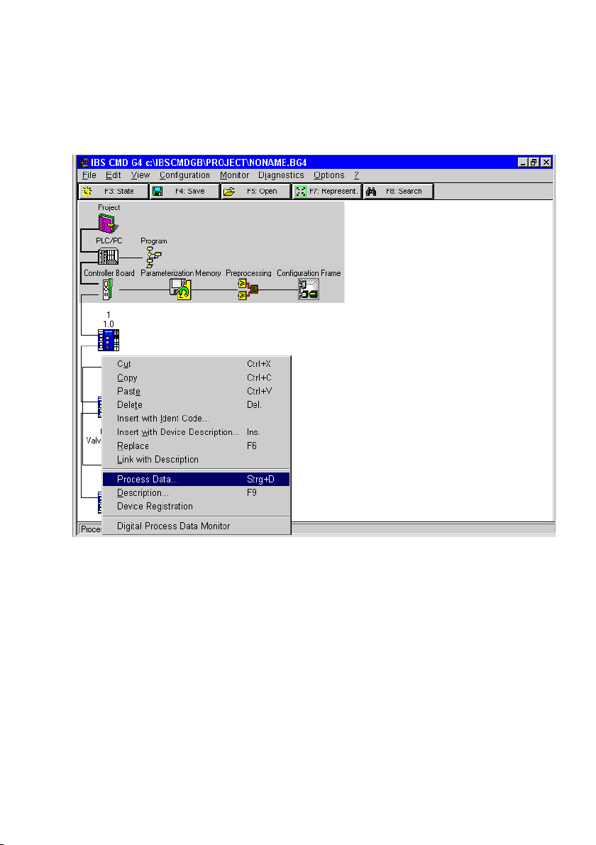
2. Commissioning
Fig.2/9: Select option for entering the process data
Festo P.BE−CP−FB6−E−EN en 0802g
2−27
Page 58
2. Commissioning
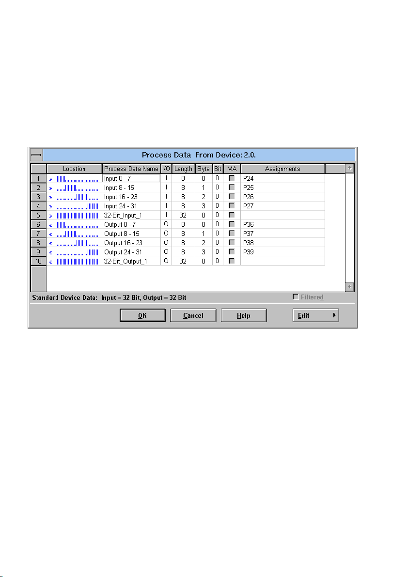
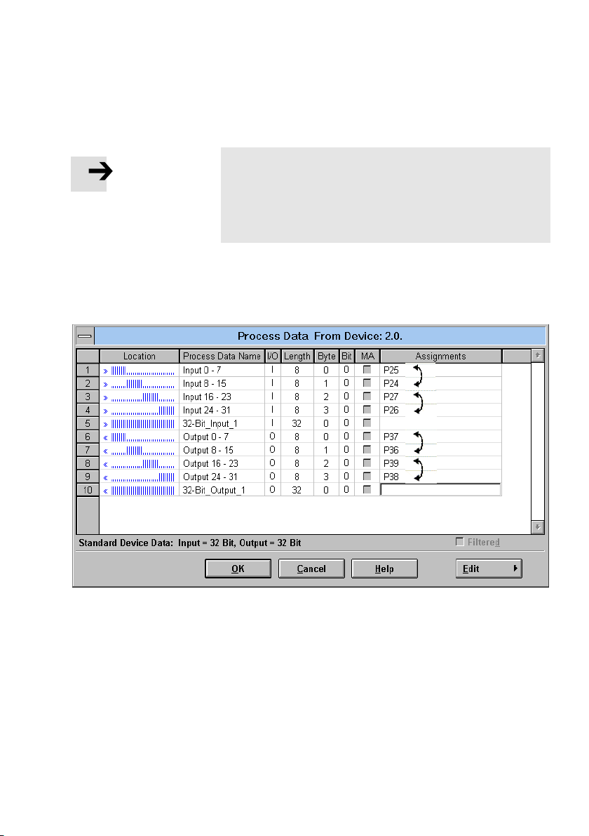
You can determine the I/O addresses in the following dia
logue window (example: Siemens mode, " byte−by−byte as
signment for an S5):
Fig.2/10: Entering process data example of Siemens mode"
2−28
Festo P.BE−CP−FB6−E−EN en 0802g
Page 59
2. Commissioning
Please note
In order to correct the byte swap, you need only assign the
appropriate I/O address to each byte.
Individual I/O assignment at bit level is only necessary in
special cases.
The following dialogue window shows the entries required for
swapping the assignment of the high byte and the low byte
(example: byte
swap for Standard mode").
Fig.2/11: Modifying the I/O assignment example for Standard mode"
Festo P.BE−CP−FB6−E−EN en 0802g
2−29
Page 60
2. Commissioning
2.4.4 Other instructions
Preprocessing
Under preprocessing on the INTERBUS we understand the
logical linking of the processing data within the INTER BUS
module (previously called Event programming" or Receive
bit manipulation").
Please note
All the inputs/outputs of a CP system can be prepro
cessed.
Periphery faults (PF)
If a fault is recognized by the CP system, a periphery fault will
also be triggered, transmitted to the module and displayed
there. The causes of the fault in the CP system can, however,
be partly suppressed (see Chapter 3.3.2).
2−30
Periphery faults do not cause the system to stop. You can
determine the
the module. You can also acknowledge the periphery fault by
parametrizing the INTERBUS module.
reaction to periphery faults by parametrizing
Festo P.BE−CP−FB6−E−EN en 0802g
Page 61

2. Commissioning
Commissioning tips
If the error message PF" appears when the power supply is
switched on, one of the causes is that load voltage for the
valves and electrical outputs is not switched on (pin 2 of the
power supply connections of the valve terminal is without
voltage). This is always the case when the load
switched on until after the power−up phase of the controller.
Due to the factory setting of DIL switch element 2, this leads
correctly to an error message.
Recommendation:
In this case, switch off the monitoring of the valve/output
voltage and evaluate the undervoltage message via the diag
nostic status register.
voltage is not
Festo P.BE−CP−FB6−E−EN en 0802g
2−31
Page 62

2. Commissioning
2−32
Festo P.BE−CP−FB6−E−EN en 0802g
Page 63

Diagnosis
Chapter 3
3−1Festo P.BE−CP−FB6−E−EN en 0802g
Page 64

3. Diagnosis
Contents
3. Diagnosis 3−1 . . . . . . . . . . . . . . . . . . . . . . . . . . . . . . . . . . . . . . . . . . . . . . . . . . . . .
3.1 LED displays on the bus node 3−3 . . . . . . . . . . . . . . . . . . . . . . . . . . . . . . . . . . . . .
3.1.1 Normal operating status 3−5 .
3.1.2 Diagnosis power supply POWER or POWER V 3−6 . . . .
3.1.3 Diagnostic bus LEDs 3−7 . . . . . . . . . . . . . . . . . . . . . . . . . . .
3.2 Testing the valves 3−9 . . . . . . . . . . . . . . . . . . . . . . . . . . . . . .
3.3 Diagnosis via INTERBUS 3−11 . . . . . . . . . . . . . . . . . . . . . . . . . . . . . .
3.3.1 Diagnostic status register 3−11 . . . . . . . . . . . . . . . . . . . . . . . . . . . . . . . . . . . . .
3.3.2 Periphery fault (PF) 3−12 . . . . . . . . . . . . . . . . . . . . . . . . . . . . . . . . . . . . . . . . . . . .
3.4 Reaction to faults in the control system 3−13 . . . . . . . . . . . . . . . . . . . . . . . . . . . . .
. . . . . . . . . . . . . . . . . . . . . . . . . . . . . . . . . . . . . . . .
. . . . . . . . . . . . . . . . . . . .
. . . . . . . . . . . . . . . . . .
. . . . . . . . . . . . . . . . .
. . . . . . . . . . .
. . .
. .
3−2
Festo P.BE−CP−FB6−E−EN en 0802g
Page 65
3. Diagnosis
3.1 LED displays on the bus node
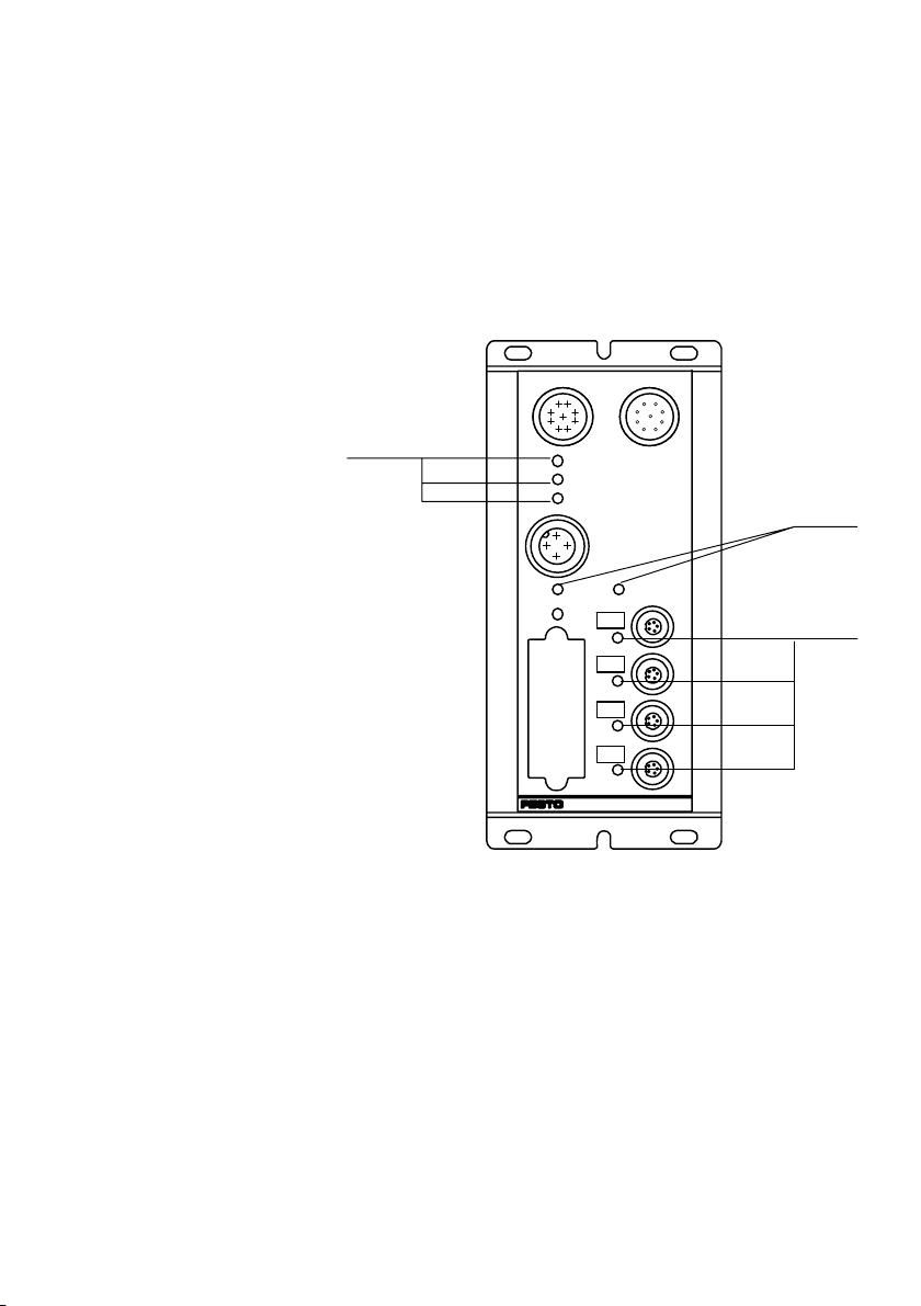
The LEDs on the node permit fast on−the−spot diagnosis.
1 INTERBUS spe
cific LEDs
2 Power supply
LEDs
3 String LEDs
1
RC
BA
RD
POWER
SAVE
ERRORV
Fig.3/1: LEDs of CP node FB6
24VDC
0
1
2
3
2
POWERV
3
Festo P.BE−CP−FB6−E−EN en 0802g
3−3
Page 66

3. Diagnosis
LEDs LED designation Meaning
RC Remote bus check Lights up when connection is made to the master
BA Bus active Lights up during data transfer
RD Remote bus disable Lighs up when data transfer on the bus is interrupted
POWER Operating voltage display
of internal electronics
POWER V Load voltage display of
valves
0..3 CP string LED In starting phase:
or when interface REMOTE OUT" is switched off.
Lights up when operating voltage is applied to pin 1
and the node is ready to operate.
Lights up when load voltage is OK (pin 2)
blinks if the string assignment has been modified since
last operation.
During operation:
lights up if a CP connection is interrupted.
3−4
Festo P.BE−CP−FB6−E−EN en 0802g
Page 67
3. Diagnosis
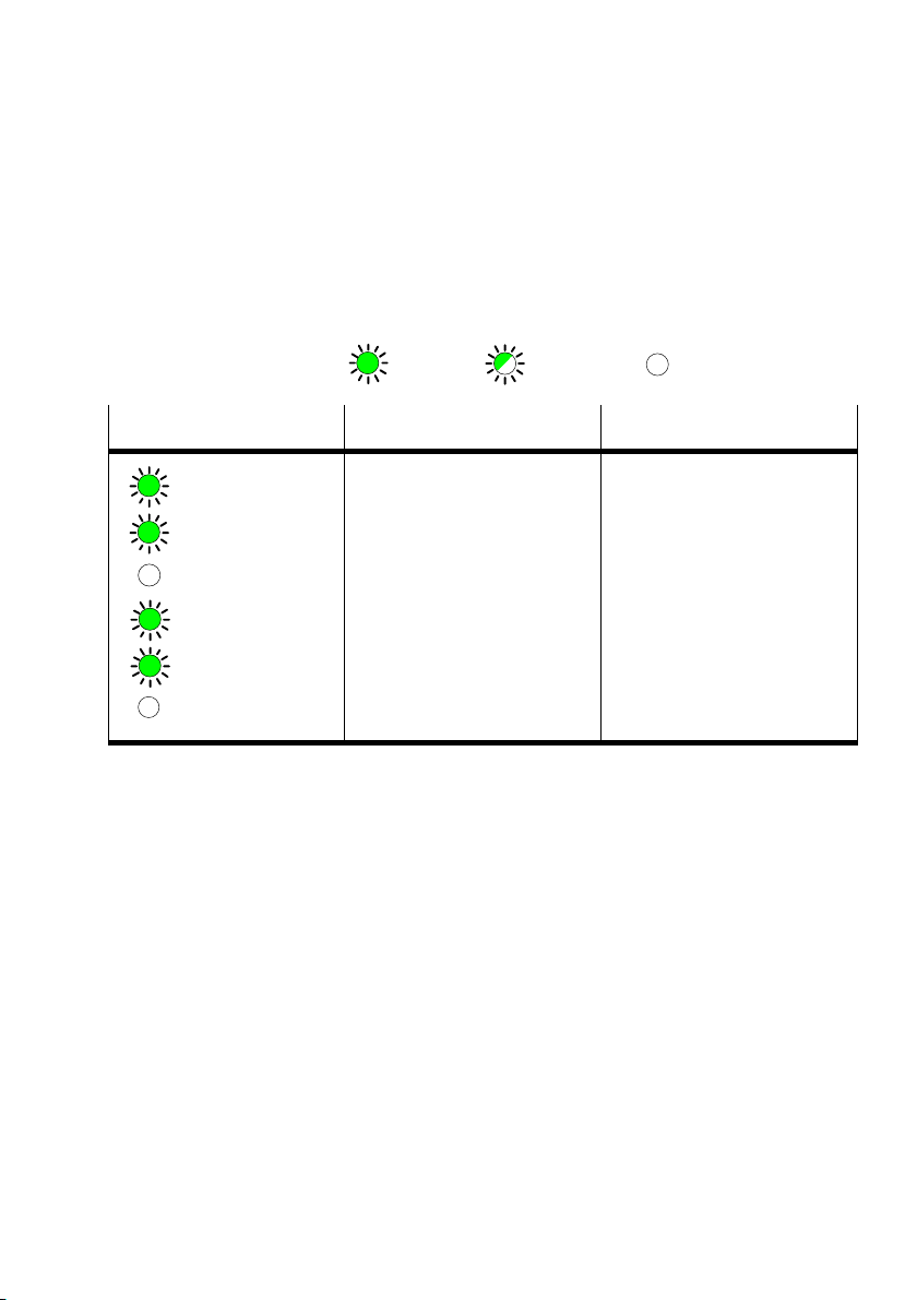
3.1.1 Normal operating status
In normal operating status the following LEDs on CP node 6
light up:
( lights up; LED flashes; out)
LED
Operating status Error treatment
normal none
RC
BA
RD
POWER
POWER V
0...3 ERROR
Festo P.BE−CP−FB6−E−EN en 0802g
3−5
Page 68
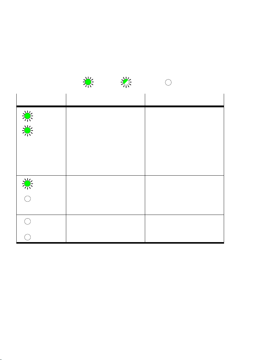
3. Diagnosis
3.1.2 Diagnosis power supply POWER or POWER V
( lights up; LED flashes; out)
LEDs
POWER
POWER V
POWER
POWER V
POWER
POWER V
Operating status Error treatment
Operating status normal
or
Operating status normal, but
valves do not switch.
compressed air supply not
correct
pilot exhaust blocked
or
operating status normal, but
INTERBUS error message of the
LEDs RC, BA, RD
Load voltage of the outputs (pin
2) not in tolerance range or not
applied.
or
CP valve terminal or output mod
ule defective.
Operating voltage for electronic
components (pin 1) not applied
or
Hardware error
None
Check the ...
S compressed air supply
S pilot exhaust channels
See error message of the LEDs RC,
BA, RD
S Check load voltage of valves (pin 2)
or
S Replace CP module
S Check operaing voltage connec
tion
or
S Servicing required
3−6
Festo P.BE−CP−FB6−E−EN en 0802g
Page 69
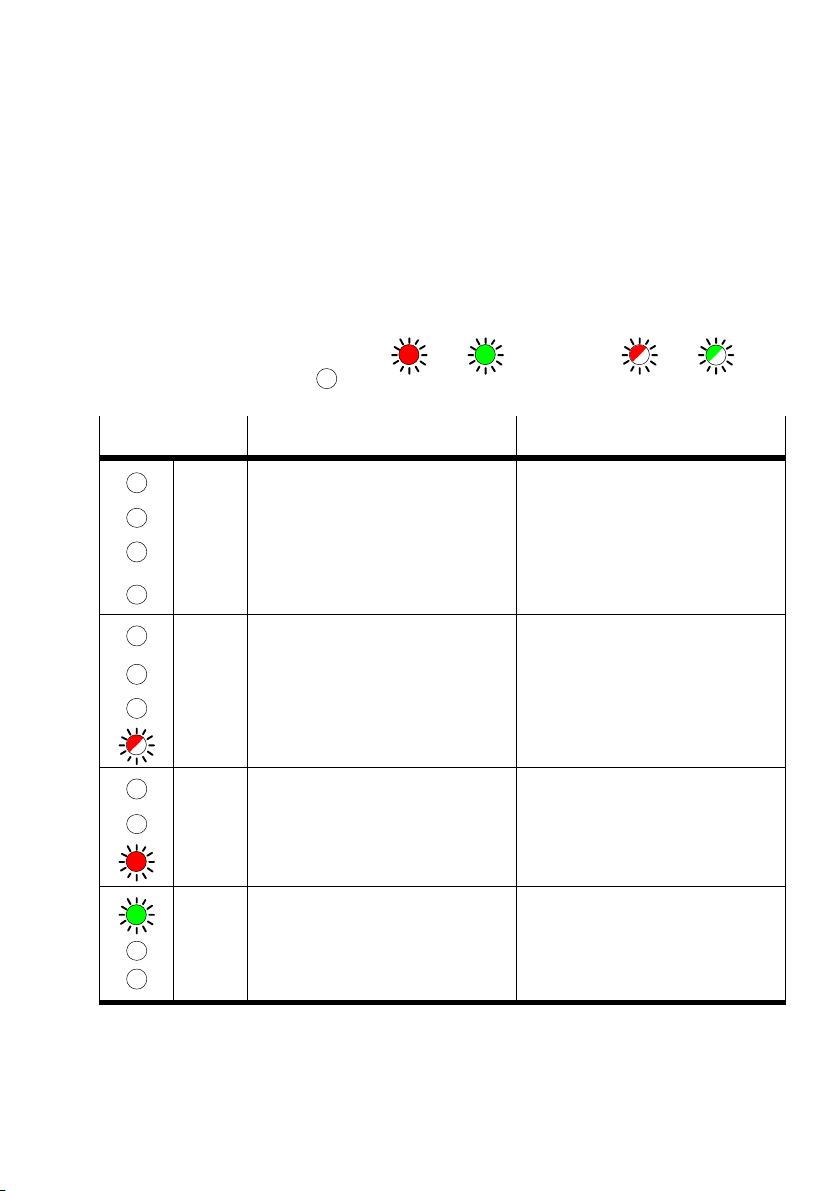
3. Diagnosis
3.1.3 Diagnostic bus LEDs
The table below shows the possible INTERBUS specific LED
displays on the operating status of the CP node (Error dis
plays RC, BA, RD):
LEDs
RC
BA
RD
String x
RC
BA
RD
String x
RC
BA
RD
RC
(lights up red green; flashes red
out)
Operating status Error treatment
Valve test mode is switched on.
If valves do not switch:
CP connection is interrupted
hardware error
Valve test mode is switched on
or
string assignment of CP system has
been modified
INTERBUS fault, either:
bus not connected or interrupted
interface switched off
No data transfer Check operating status of module
S Check CP connecting cable
S Servicing required
S Exit the self test by switching off
the power supply
or
S check/correct string assignment, or
press the SAVE button in order to
save the new string assignment
S Check or connect bus cable
S Programmed switch off by master
S Reset status on IBS
green
BA
RD
Festo P.BE−CP−FB6−E−EN en 0802g
3−7
Page 70
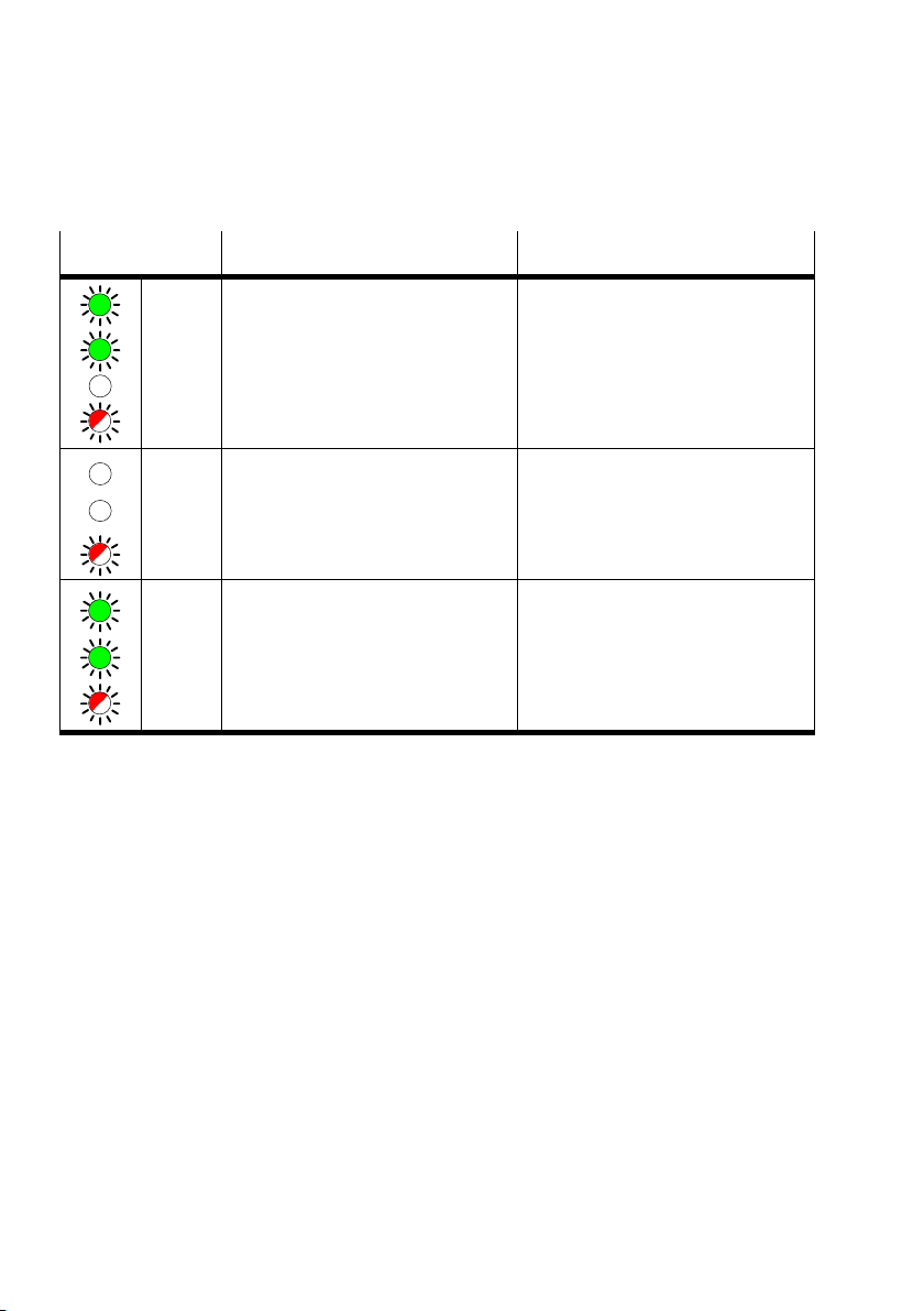
3. Diagnosis
LEDs Error treatmentOperating status
RC
BA
RD
String x
RC
BA
RD
RC
BA
RD
String assignment modified:
INTERBUS is active; Data exchange
with CP system is blocked.
INTERBUS not active
By pressing the SAVE button you can
change the address length of the CP
system compared with the last saved
INTERBUS active;
Data exchange with CP system
blocked, as address length in the
module and string assignment on CP
system differ.
S Adapt string assignment
or
S press SAVE button to save new
string assignment
S Switch off the power supply and
then switch on again.
When switched on, the CP system is
available for the field bus module with
the new saved address length.
S Switch off the power supply and
then switch on again.
When switched on, the CP system is
available for the field bus module with
the new saved address length.
3−8
Festo P.BE−CP−FB6−E−EN en 0802g
Page 71
3. Diagnosis
3.2 Testing the valves
Warning
Before starting the test,
switch off the compressed air supply to the valves.
You thereby avoid undesired or dangerous movements of the
actuators.
Caution
S This test function runs automatically in the CP valve ter
minals. All valves are switched on/off cyclically.
S All programmed interlocks or continue conditions are
ignored.
Test routine During the test routine of the CP terminal, all the valves will
be switched on/off at 1 second intervals.
Festo P.BE−CP−FB6−E−EN en 0802g
3−9
Page 72

3. Diagnosis
Starting the test routine
1. Switch off the power supply (pins 1 and 2) at the node.
2. Switch off the load voltage supply at the output modules.
3. Remove the DIL switch cover.
4. Note the settings of the DIL switch.
5. Set DIL switch element 1 to OFF.
6. Switch on the operating voltages (pins 1 and 2).
7. Set DIL switch element
If the 5 second interval is exceeded, the CP valve terminal/
CPsystem will resume normal operation.
Then switch on the operating voltage at the output modules
again.
1 to ON within 5 seconds.
Stoppping the test routine
1. Switch off theoperating voltages (pins 1 and 2) of the ter
minal.
As DIL switch element 1 is set to ON = Test routine off the
CPsystem will start again when the power is switched on
without the test routine.
3−10
Festo P.BE−CP−FB6−E−EN en 0802g
Page 73
3. Diagnosis
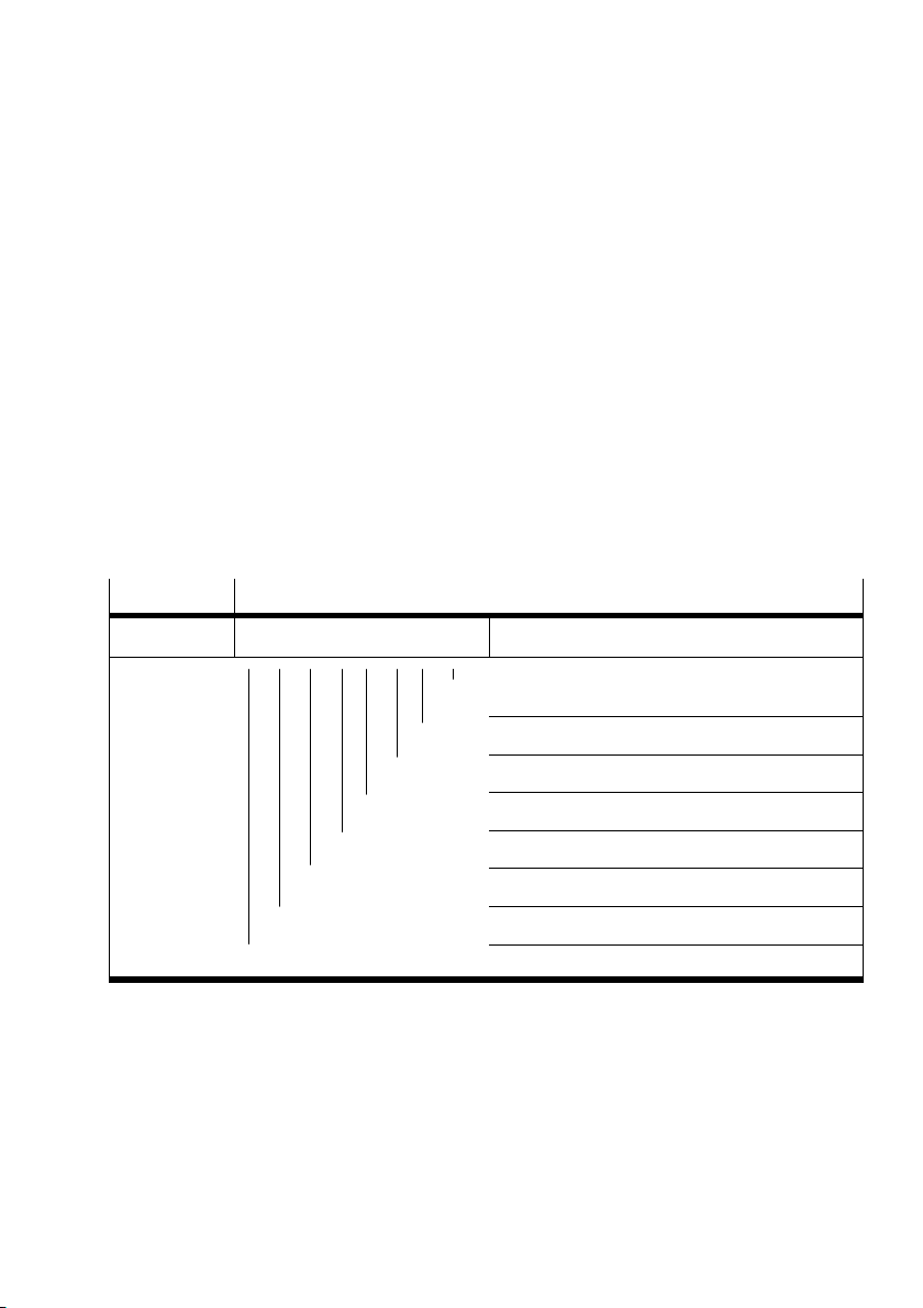
3.3 Diagnosis via INTERBUS
The CP system makes available the following diagnostic op
tions via the INTERBUS:
Entries in the diagnostic status register of the module.
3.3.1 Diagnostic status register
The diagnostic register of the module is structured specifi
cally for the INTERBUS and contains the following diagnostic
information:
n
7 0 7 6 5 4 3 2 1 0
n+1
READY
RUN
ACTIVE
CTRL
DETECT
BUS
User fault parametrizing
USER
PF
Periphery fault, e.g. valve terminal
Bus fault
Fault in module/hardware
Diagnostic routine is active
Diagnostic transmission is active
Selected configuration is ready to run
Module is ready to run
Fig.3/2: Structure of the diagnostic status register
The CP system triggers PF Periphery fault" as a common
error message.
Festo P.BE−CP−FB6−E−EN en 0802g
3−11
Page 74
3. Diagnosis
2
3.3.2 Periphery fault (PF)
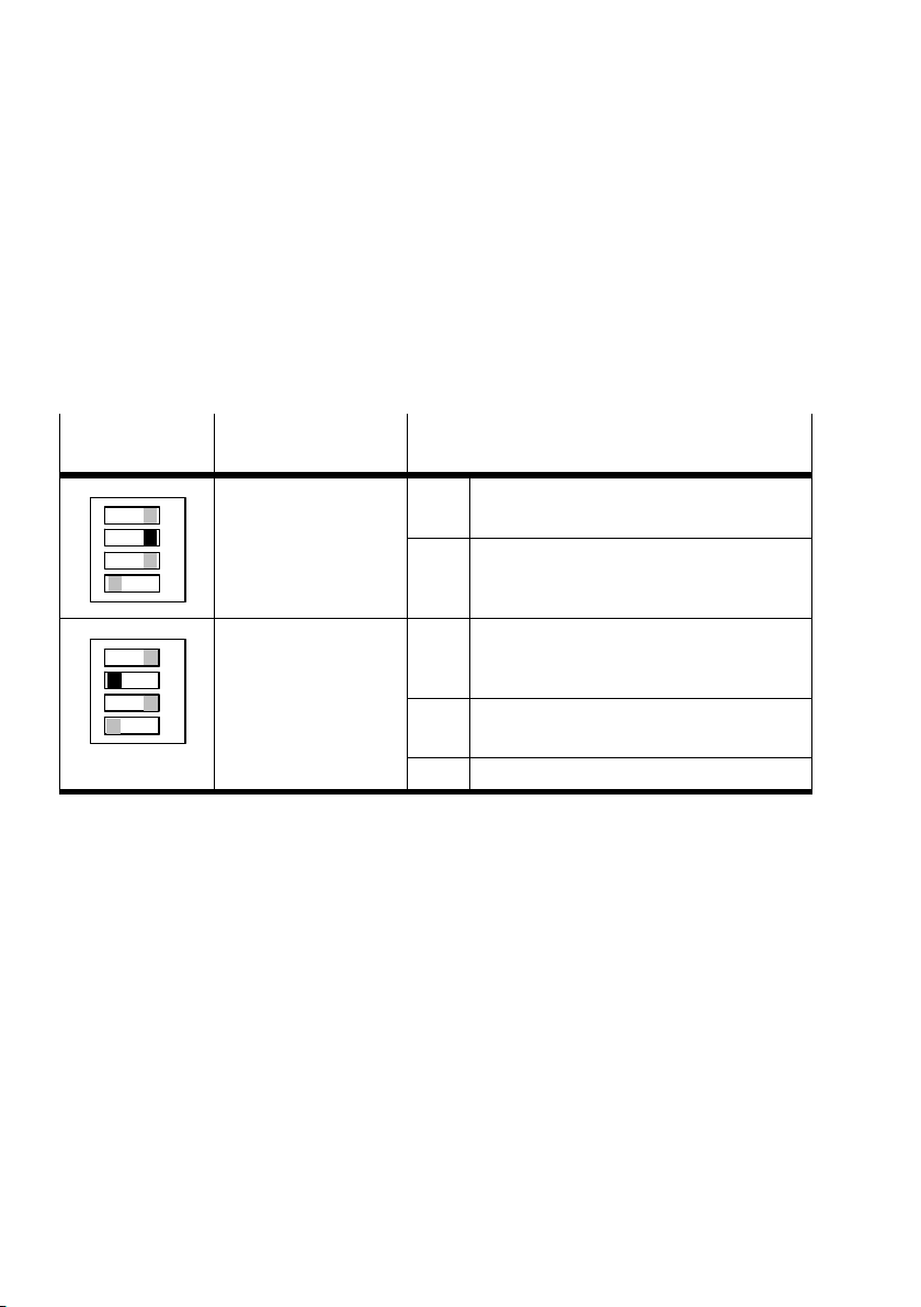
Possible causes If an error is recognized by the bus node of the CP system, a
periphery fault will be triggered, depending on the setting of
DIL switch element 2. The error will then be transferred to the
interface module and displayed.
DIL switch
element 2
3
4
2
3
4
Selection Error
Errors 1 and 2 are not
ON1
transmitted
Factory setting:
ON1
All errors 1 ... 5 are
transmitted
The system is not stopped by a periphery fault. A reaction can
be programmed (e.g acknowledge errors, stop running sys
tem, restart system).
1 Voltages for valves below tolerance
(< 21.6V)
2 Voltage for valves switched off
(e.g. EMERGENCY STOP)
3 Supply to inputs/sensors switched off
(e.g. internal fuse triggered)
4 Short circuit or overload at digital outputs
5 CP connection interrupted
3−12
Festo P.BE−CP−FB6−E−EN en 0802g
Page 75

3. Diagnosis
3.4 Reaction to faults in the control system
Reaction of the system to faults
of the INTERBUS in the control system
In the case of field bus faults
due to failure of the field bus sig
nal or interruption of the field
bus cable all outputs (valves and
electrical outputs) will be
switched off after 25 ms.
With programmed INTERBUS
reset or processor reset, all out
puts (valves and electrical out
puts) on the CP system will be
switched off.
Please note.
unilaterally−actuated valves
move to the basic position
double solenoid valves remain
in the current position
Festo P.BE−CP−FB6−E−EN en 0802g
3−13
Page 76

3. Diagnosis
3−14
Festo P.BE−CP−FB6−E−EN en 0802g
Page 77

Technical appendix
Appendix A
A−1Festo P.BE−CP−FB6−E−EN en 0802g
Page 78

A. Technical appendix
Contents
A. Technical appendix A−1 . . . . . . . . . . . . . . . . . . . . . . . . . . . . . . . . . . . . . . . . . . . . .
A.1 Technical specifications A−3 . .
A.2 Index A−5 . . . . . . . . .
. . . . . . . . . . . . . . . . . . . . . . . . . . . . . . . . . . . . . . . . . . . . . . . .
. . . . . . . . . . . . . . . . . . . . . . . . . . . . . . . . . . . . . . . .
A−2
Festo P.BE−CP−FB6−E−EN en 0802g
Page 79

A. Technical appendix
A.1 Technical specifications
General
Temperature range
operation
storage/transport
Relative humidity 95%, non condensing
−5 °C ... + 50 °C
−20 °C ... + 70 °C
Protection class as per EN 60 529
Plug connector plugged in or fitted with protec
tive cap
Protection against electric shock
(protection against direct and indirect contact as
per IEC/DIN EN 60204−1)
Chemical resistance See Festo pneumatics catalogue
IP 65
by means of PELV circuits
(ProtectiveExtra−Low Voltage)
(table of resistances)
Festo P.BE−CP−FB6−E−EN en 0802g
A−3
Page 80
A. Technical appendix
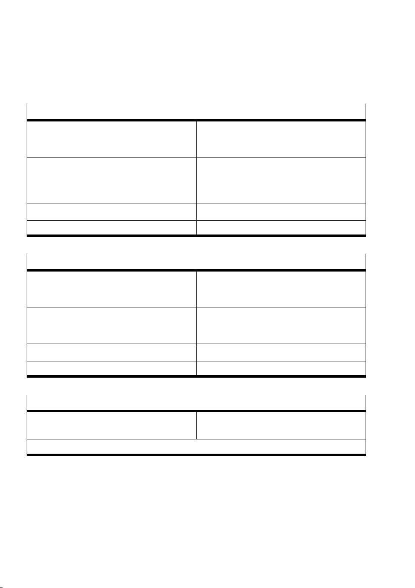
Operating voltage Electronic components and input modules
Operating voltage connection (Pin 1)
rated value
tolerance
Current consumption
Pin 1 node FB6−E
Complete electronics of the CP system
Residual ripple 4 Vpp (within tolerance)
Power failure bridging time 20 ms
DC 24 V
20,4 .. 26,4 V
250 mA
see CP system" manual, Chapter 3.1.2, Table of
current consumption
Load voltage Solenoid valves of CP terminal
Operating voltage connection (Pin 2)
rated value
tolerance
DC 24 V
20,4 .. 26,4 V
Current consumption
Pin 2 node FB6−E Sum of all connected CP solenoid valves; see CP
Residual ripple 4 Vpp (within tolerance)
Power failure bridging time 20 ms
pneumatics" manual
Electromagnetic compatibility
Interference emitted
Immunity against interference
1)
The component is intended for industrial use.
A−4
Tested as per DIN EN 61000−6−4 (industry)
Tested as per DIN EN 61000−6−2 (industry)
Festo P.BE−CP−FB6−E−EN en 0802g
1)
Page 81

A. Technical appendix
A.2 Index
A
Abbreviations, product−specific X. . . . . . . . . . . . . . . . . . . . . . .
Address assignment 2−21. . . . . . . . . . . . . . . . . . . . . . . . .
Addressing
logical 2−14. . . . . . . . . . . . . . . . . . . . . . . . . . . . . . . . . . . . . . .
manufacturer−specific 1−5. . . . . .
physical 2−17. . . . . . . . . . . . . . . . . . . . . . . . . . . . .
Ascertaining the ID code 2−15. . . . . . . . . . . . . . . . . . . . . . . . . .
Ascertaining the process data channel bits 2−15. . . . . .
. . . . . . . . . . . . . . . . . . . . .
. . . .
. . . . . . . . .
. . . . .
B
Festo P.BE−CP−FB6−E−EN en 0802g
Bus LEDs, diagnosis 3−7. . . . . . . . . . . . . . . . . . . . . . . . . . . . . . .
Byte swap 2−23. . . . . . . . . . . . . . . .
. . . . . . . . . . . . . . . . . . . . . .
C
Configuration list 2−4. . . . . . . . . . . . . . . . . . . . . . . . . . . . . . . . .
creating 2−4. . . . . . . . . . . . . . . .
Configuration run 2−19. . . . . . . . . . . . . . . . . . . . . . . . . .
Connecting, INTERBUS interface 1−6. . . . . . . . . . . . . . . . . . . .
Connection variants 1−7. . . . . . . . . . . . . . . . . . . .
CP system
operating voltage 2−3. . . . . . . . . . . . . . . . . . . . . . . . . . . . . . .
preparing for operation on the INTERBUS 2−3
. . . . . . . . . . . . . . . . . . . . . . .
. . . . . .
. . . . . . . . . . .
. . . . . . . . . . .
A−5
Page 82

A. Technical appendix
D
Designated use V. . . . . . . . . . . . . . . . . . . . . . . . . . . . . . . . . . . .
Diagnosis
bus LEDs 3−7. . . . . . . . . . .
diagnostic register 3−11. . . . . . . . . . . . . . . . . . . . . .
operating voltage LEDs 3−6. . . . . . . . . . . . . . . . . . . . . . . . . .
. . . . . . . . . . . . . . . . . . . . . . . . . . .
. . . . . . .
E
Errors, treatment 3−11. . . . . . . . . . . . . . . . . . . . . . . . . . . . . . . .
F
Faults
field bus 3−13. . . . . . . . . . . . . . . . . . . . . . . . . . . . . . . . . . . . .
PLC 3−13. . . . . . . . . . .
Floating structure 1−8. . . . . . . . . . . . . . . . . .
. . . . . . . . . . . . . . . . . . . . . . . . . . . . . . .
. . . . . . . . . . . . . . .
A−6
I
Important user instructions VII. . . . . . . . . . . . . . . . . . . . . . . . .
Installation remote bus
connection 1−15. . . . . . . . . . . . . . . . . . . .
continuing 1−16. . . . . . . . . . . . . . . . . . . . . . . . . . . . . . . . . . .
incoming 1−15. . . . . . . . . . . . . . . . . . . . . . . . . . . . . . . . . . . . .
non−floating 1−15. . . . . . . . . . . .
INTERBUS
addressing 2−4, 2−21. . . . . . . . . . . . . . . . . . . . . . . . . .
preparing 2−4. . . . . . . . . . . . . . . . . . . . . . . . . . . . . . . . . . . . .
INTERBUS interface, connecting 1−6. . . . . .
. . . . . . . . . . . . . . . . . . . . . .
. . . . . . . . . . . . . . .
. . . . .
. . . . . . . . . . . . . . .
Festo P.BE−CP−FB6−E−EN en 0802g
.
Page 83

A. Technical appendix
L
LEDs 3−3. . . . . . . . . . . . . . . . . . . . . . . . . . . . . . . . . . . . . . . . . . .
diagnosis 3−6, 3−7. . . . . .
Logical addressing 2−14. . . . . . . . . . . . . . . . . . . . .
. . . . . . . . . . . . . . . . . . . . . . . . . . . .
. . . . . . . . . .
M
Manufacturer−specific addressing 1−5, 2−23. . . . . . . . . . . . . .
N
Nominal/actual configurations 2−4. . . . . . . . . . . . . . . . . . . . . .
Non−floating remote bus 1−12. . . . . . . . . . . . . . . . . . . . . . . . .
Non−floating structure 1−9. . . . . . . . . . . . . . . . . . . . . . . . . . . . .
Notes on the use of this manual VI. . . . . . . . . . . .
.
. . . . . . . . . .
Festo P.BE−CP−FB6−E−EN en 0802g
O
Operating status 3−5. . . . . . . . . . . . . . . . . . . . . . . . . . . . . . . . .
Operating voltage, CP system 2−3. . . . . . . . . . . . .
. . . . . . . . . .
P
Physical addresses, calculating 2−18. . . . . . . . . . . . . . . . . . . .
Physical addressing 2−17. . . . . . . . . . . . . . . . . . . . . . . . . . .
POWER LEDs, diagnosis 3−6. . . . . . . . . . . . . . . . . . . . . . . . . . . .
Power supply 1−18. . . . . . . . . . . . . . .
. . . . . . . . . . . . . . . . . . . .
. . .
A−7
Page 84

A. Technical appendix
R
Remote bus
connection 1−10. . . . . . . . . . . . . . . . . . . . . . . . . . . . . . . . . . .
floating 1−10. . . . . . . . . . . . .
incoming 1−13. . . . . . . . . . . . . . . . . . . . . . . . .
Remote field bus, continuing 1−14. . . . . . . . . . . . . . . . . . . . . .
. . . . . . . . . . . . . . . . . . . . . . . . .
. . . . . . . . . . . .
S
SAVE, string assignment 2−3. . . . . . . . . . . . . . . . . . . . . . . . . . .
Screening/shielding variants 1−7. . . . . . . . . . . . . . . . . . . .
Service VI. . . . . . . . . . . . . . . . . . . . . . . . . . . . . . . . . . . . . . . . . .
Siemens, settings 1−4, 2−3.
String assignment, saving 2−3. . . . . . . . . . . . . . . . . . . . .
Switching status, valves 3−9. . . . . . . . . . . . . . . . . . . . . . . . . . .
. . . . . . . . . . . . . . . . . . . . . . . . . . .
. . .
. . . . .
A−8
T
Target group VI. . . . . . . . . . . . . . . . . . . . . . . . . . . . . . . . . . . . . .
Technical specifications A−3. . . . . . . . . .
Test routine for valves 3−9. . . . . . . . . . . . . . . . . . . . . . . . . . . . .
. . . . . . . . . . . . . . . . . .
Festo P.BE−CP−FB6−E−EN en 0802g
 Loading...