

Page 1

Compact Performance
Manual
Programming and
diagnosing
CP field bus
node13
Type CP−FB13−E
Field bus
connection
PROFIBUS−DP
asperEN50170
Manual
165 213
en 0802h
[730 623]
Page 2

Page 3

Contents and general instructions
Original de. . . . . . . . . . . . . . . . . . . . . . . . . . . . . . . . . . . . . . .
Edition en 0802h. . .
DesignationP.BE−CP−FB13−E−EN. . . . . . . . . . . . .
. . . . . . . . . . . . . . . . . . . . . . . . . . . . . . .
. . . . . . . . .
Order no. 165 213. . . . . . . . . . . . . . . . . . . . . . . . . . . . . . . . .
E (Festo
AG&Co. KG, D73726 Esslingen, Federal Republic
of Germany, 2008)
Internet: http://www.festo.com
E−Mail: service_international@festo.com
The copying, distribution and utilization
of this document as
well as the communication of its contents to others without
expressed authorization is prohibited. Offenders will be held
liable for t
he payment of damages. All rights are reserved, in
particular the right to carry out patent, utility model or orna
mental design regis
Festo P.BE−CP−FB13−E−EN en 0802h
tration.
I
Page 4

Contents and general instructions
II
Festo P. BE−CP−FB13−E−EN en 0802h
Page 5

Contents and general instructions
Contents
Designated use IV . . . . . . . . . . . . . . . . . . . . . . . . . . . . . . . . . . . . . . . . . . . . . . . . . . . . . . . .
Target group V . . . . . . . . . . . . . . . . . . . . . . . . . . . . . . . . . . .
Service V . . . . . . . . . . . . . . . . . . . . . . . .
Notes on the use of this manual
Important user in
structions VI . . . . . . . . . . . . . . . . . . . . . . . . . . . . . . . . . . . . . . . . . . . . . .
. . . . . . . . . . . . . . . . . . . . . . . . . . . . . . . . . . . . . . .
. . . . . . . . . . . . . . . . . . . . . . .
V . . . . . . . . . . . . . . . . . . . . . . . . . . . . . . . . . . . . . . . . . . .
1. Installation 1−1 . . . . . . . . . . . . . . . . . . . . . . . . . . . . . . . . . . . . . . . . . . . . . . . . .
1.1 General instructions on installation 1−3 . . . . . . . . . . . . . . . . . . . . . . . . . . . . . . .
1.2Configuring the field bus node1−5 . . . . . . . . . . . . . . . . . . . . . . . . . . . . . . . . . . . .
2.1 Setting the field bus node1−5 . . . . . . . . . . . . . . . . . . . . . . . . . . . . . . . . .
1.
1.3Connecting t
1.3.1 Field bu
1.3.2 Field bu
1.3.3 Field bus interface 1−12 . . . . . . .
1.3.4 Connection possibilities 1−13 . . . . . . . .
1.4 Bus termination with terminating resistors1−17 . . . . .
1.5Connecting the CP modules 1−18 . . . . . . . . . . . . . . . . . .
1.6Connecting the power supply 1−19 . . . . . . . . . . . . . . . .
2. Commissioning 2−1 . . . . . . . . . . . . . . . . . . . . . . . . . . . .
2.1 Preparing the CP system for commissioning 2−3 . . . . . . . . . . . .
2.1.1 Saving the string assignment 2−3 . . . . . . . . . . . . . . . . . . . . . . . .
2.1.2Information on commissioning 2−5 . . . . . . . . . . . . . . . . . . . . . . . . . . . . .
2.2Device
2.3Configuration with a
2.3.1 STEP 7 HW Config (up to
2.3.2 Examples of addressing 2−20 . . . . . . . .
2.3.3Commissioning the CP system on the PROFIB US−DP 2−24 . . . .
he field bus1−9 . . . . . . . . . . . . . . . . . . . . . . . . . . . . . . . . . . . . . . . . .
s cable 1−9 . . . . . . . . . . . . . . . . . . . . . . . . . . . . . . . . . . . . . . . . . .
s baud rate and field bus length1−11 . . . . . . . . . . . . . . . . . . . . .
. . . . . . . . . . . . . . . . . . . . . . . . . . . . . . . .
. . . . . . . . . . . . . . . . . . . . . . . . . .
. . . . . . . . . . . . . . . . . . . . .
. . . . . . . . . . . . . . . . . . . . .
. . . . . . . . . . . . . . . . . . . . .
. . . . . . . . . . . . . . . . . . . .
. . . . . . . . . . . . .
. . . . . .
master file (GSD) and icon files 2−12 . . . . . . . . . . . . . . . . . . . . . . . . . . . . . .
Siemens master 2−13 . . . . . . . . . . . . . . . . . . . . . . . . . . . . . . .
V 5.2) 2−14 . . . . . . . . . . . . . . . . . . . . . . . . . . .
. . . . . . . . . . . . . . . . . . . . . . . . . .
. . . . . . .
. .
.
3. Diagnosis and error treatment 3−1 . . . . . . . . . . . . . . . . . . . . . . . . . . . . . . . . . . . .
3.1 LED
Festo P. BE−CP−FB13−E−EN en 0802h
displays on the bus node3−3 . . . . . . . . . . . . . . . . . . . . . . . . . . . . . . . . . . . . .
3.1.
1 Normal operating status3−4 . . . . . . . . . . . . . . . . . . . . . . . . . . . . . . . . . .
III
Page 6

Contents and general instructions
3.1.2 Fault display of the POWE R LEDs 3−5 . . . . . . . . . . . . . . . . . . . . . . . . . . .
3.1.3 Fault messages
3.2 Testing the valves 3−7 . . . . . . . . . . .
3.3 Diagnosis via PROFIBUS−DP 3−9 . . . . .
3.3.1 Diagnostic words3−9 . . . . . . . . .
3.3.2 Diagnostic steps3−10 . . . . . . . . . . .
3.3.3Overview of diagnostic bytes 3−11 . . . . . . . . .
of the LED BUS ERROR 3−6 . . . . . . . . . . . . . . . . . . . . . .
. . . . . . . . . . . . . . . . . . . . . . . . . . . . . . . . . . . .
. . . . . . . . . . . . . . . . . . . . . . . . . . . . . . . . .
. . . . . . . . . . . . . . . . . . . . . . . . . . . . . . .
. . . . . . . . . . . . . . . . . . . . . . . . . . . . .
. . . . . . . . . . . . . . . . . . . . .
3.3.4 Details for standard diagnostic information 3−12 . . . . . . . . . . .
3.4 Fault treatment 3−17 . . . . . . . . . . . . . . . . . . . . . . . . . . . . . . . . . . .
. . . . . . . . . . . . . .
3.4.1 Siemens SIMATIC S5/S73−18 . . . . . . . . . . . . . . . . . . . . . . . . . .
3.5Online diagnosis with STEP 73−20 . . . . . . . . . . . . . . . . . . . . . . . . . . . . . .
3.5.1 Read diagnostic buffer with STEP 7 (up to V 5.2) 3−20 . . . . . . . . . . . . . .
3.6 Short circuit/over
3.6.1Output mo
load 3−22 . . . . . . . . . . . . . . . . . . . . . . . . . . . . . . . . . . . . . . . . . . .
dule 3−22 . . . . . . . . . . . . . . . . . . . . . . . . . . . . . . . . . . . . . . . . .
3.6.2Input module 3−24
. . . . . . .
. . . . . . . .
. . . . . . .
. . . . . . . . . . . . . . . . . . . . . . . . . . . . . . . . . . . . . . . . . . .
A. Technical appendix A−1 . . . . .
A.1 Technical specifications Field bus
. . . . . . . . . . . . . . . . . . . . . . . . . . . . . . . . . . . . . . . .
node CP FB13−E A−3 . . . . . . . . . . . . . . . . . . . .
A.2Commissioning with the general DP masterA−5 . . . . . . .
A.2.1Bus start A−5 . . . . . . . . . . . . . . . . . . . . . . . . .
. . . . . . . . . . . . . . . . . . . . . .
A.2.2 Send parametriziung data A−6 . . . . . . . . . . . . . . .
A.2.3 Check the configuration data A−7 . . . . . . . . . . . . . . . . . . . . .
A.2.4 Transferring input and output data A−9 . . . . . . . . . . . . . . . . . . . . . . . . .
A.2.5 Read dia
A.2.6Implemented functions and se
gnostic informationA−11 . . . . . . . . . . . . . . . . . . . . . . . . . . . . . . .
rvice access points (SAP) A−11 . . . . . . . .
A.2.7Bus parameters/reaction timesA−12 . . . . . . . . . . . . . . . . . . . . .
A.2.8 Transmission times on the PROFIBUS−DPA−12 . . . . . . . . . . . . . . . . . . . .
B. Index B−1 . . . . . . .
. . . . . . . . . . . . . . . . . . . . . . . . . . . . . . . . . . . . . . . . . . . . . . . . . .
IV
. . . . . . . . . . . . . . . . . . .
. . . . . . . . . . . . . . . . .
. . . . . . . . .
. . . . . . .
Festo P. BE−CP−FB13−E−EN en 0802h
Page 7

Contents and general instructions
Designated use
The CP field bus node type CP−FB13−E described in this man
ual has been designed exclusively for use as a slave on the
PROFIBUS−DP. CP modules from Festo can be connected to
CPfield bus node CP−FB13−E.
The CP node may only be used as follows:
as specified in industrial applications.
w
in faultless technical condition.
The maximum values specified for pressures, temperatures,
electrical data, torques etc. must be observed.
If add
sors and actuators are connected, the specifiedlimits for pres
sures, temperatures, electrical dat
be exceeded.
ithout any modifications by the user Only the conver
sions or modifications described in the documentation
supplied with the product are p
ermitted.
itional commercially−available components such as sen
a, torques, etc. must not
Festo P. BE−CP−FB13−E−EN en 0802h
Please comply with national and local safety laws and regula
tions.
V
Page 8

Contents and general instructions
Target group
This manual is intended exclusively for technicians trained in
control and automation technology, who have experience in
installing, commissioning, programming and diagnosing
PROFIBUS−DPslaves.
Service
Please consult your local Festo repair service if you have any
technical problems.
Notes on the use of this manual
This manual contains specific information on installing, com
missioning, programming and diagnosingCP field bus node
FB13 for PROFIBUS−DP in accordance with
EN 50170.
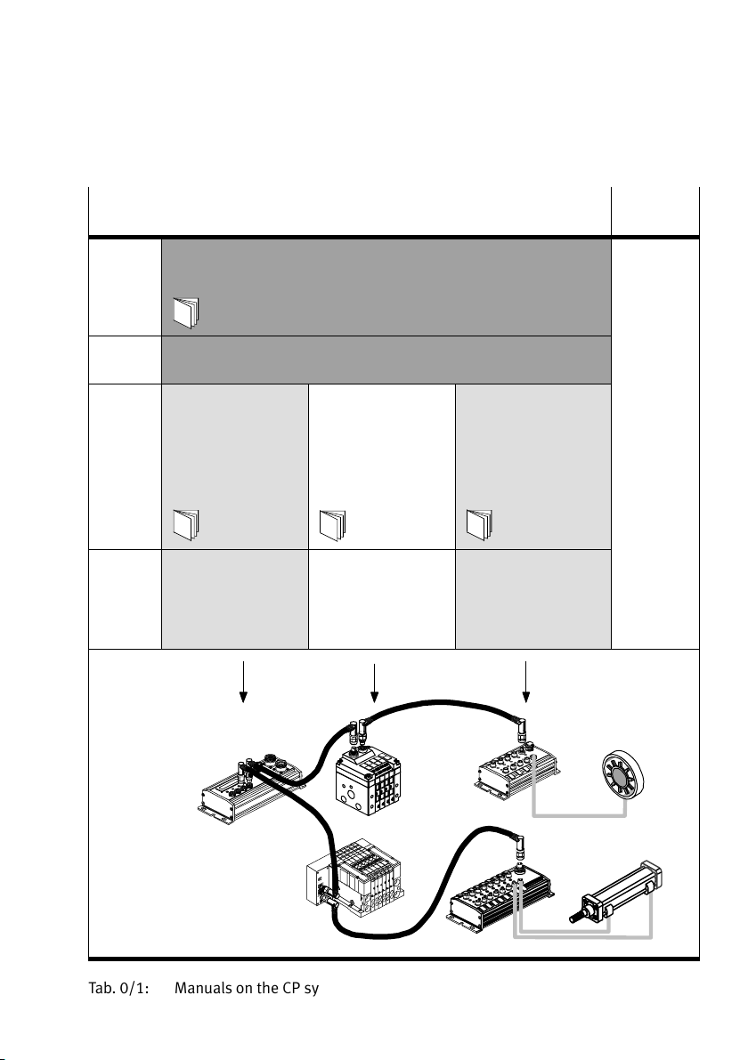
Information on further CP modules can be found in the
manual for the relevant module. An overview is provided in
Tab.0/1.
Informat
manual, P. BE−CPV−... ."
Further information on the PROF IB US−DP can be found in:
the setting up guidelines
the manuals of the master manufacturer.
VI
ion on pneumatics can be found in the Pneumatics
for the PROFIBUS−DP
Festo P. BE−CP−FB13−E−EN en 0802h
Page 9
Contents and general instructions
Important user instructions
Danger categories
This manual contains instructions on the possible dangers
which may occur if the product is not used correctly. These
instructions are marked
shaded background and marked additionally with a picto
gram. A distinction is made between the following danger
warnings:
Warning
This means that failure to observe this instruction may
result in serious personal injury or damage to property.
Caution
This means that failure to observe this instruction may
result in personal injury or damage to property.
(Warning, Caution, etc.), printed on a
Festo P. BE−CP−FB13−E−EN en 0802h
Please note
This means that failure to observe this instruction may
result in damage to property.
The following pictogram marks passages in the te
describe activities with electrostatically sensitive compo
nents.
Electrostatically sensitive components may be damaged if
they are n
ot handled correctly.
xt which
VII
Page 10

Contents and general instructions
Marking special information
The following pictograms mark passages in the text contain
ing special information.
Pictograms
Information:
Recommendations, tips and references to other sources
information.
Accessories:
Information on necessary or sensible accessories for the
Festo product.
Environment:
Information on environment−friendly use of Fest
of
o products.
VIII
Text markings
· The bullet indicates activities which may be carried out in
any order.
1.Figures denote activities which must be carried out in the
numerical order
specified.
Hyphens indicate general activities.
Festo P. BE−CP−FB13−E−EN en 0802h
Page 11
Contents and general instructions
Manuals on the CP system Peri−
pherals
Manual CP system, installation and commissioning"
Contents General basic information on the method of operation, fitting, installation
Manual CP field bus node,
Contents Special information
type P.BE−CPSYS−...
and commissioning of CP systems
programming and
diagnosis"
type P.BE−CP−FB...
or P. BE−VIFB...−10...
on commissioning,
programming and
diagnosing related
tothe node used
CPV valve terminal,
pneumatics" or
CPAvalve terminal,
pneumatics"
type P.BE−CPV−...
or P. BE−CPA−...
Information on fitting,
installing and
commissioning CPA or
CPV valve terminals
CP modules,
electronics"
type P.BE−CPEA−...
Information on fitting,
installing and
commissioning
CPI/Omodules
Tab.0/1:Manuals on the CP system
Festo P. BE−CP−FB13−E−EN en 0802h
IX
Page 12

Contents and general instructions
The following product−specific terms and abbreviations are
used in this manual:
Term/abbreviation
Busy bit Enable bit, for analysing data exchange with the CP system
CP cable Special cable for coupling the various CP modules
CP connection Plug or socket on the CP modules which enables the modules to be
CP modules Common term for various modules which can be incorporated in a
CP system Complete system consisting of CP field bus node and P modules
I Digital input
I/O modules Common term for the CP modules which provide digital inputs and
I/Os Digital inputs and outputs
Node CP field bus node with/without field bus connection to which the
O Digital output
Octet Number of address bytes assigned by the CP system
PLC/IPC Programmable logic controller/industrial PC
SAVE button Save the current string assignment (connected I/Os); when the CP
Meaning
connected with the CP cable
CPsystem
outputs (CP input modules and CP output modules)
I/Omodules are connected
system is restarted, the last saved string assignment will be compared
with thecurrent string assignment. Deviations will be indicated by flash
ing LEDs.
String Total number of I/O modules connected together on one CP connection
String assignment Total number of all I/O modules connected via strings to a CP field bus
X
of the field bus node
node (0...3)
Festo P. BE−CP−FB13−E−EN en 0802h
Page 13

Installation
Chapter 1
1−1Festo P. BE−CP−FB13−E−EN en 0802h
Page 14

1. Installation
Contents
1. Installation 1−1 . . . . . . . . . . . . . . . . . . . . . . . . . . . . . . . . . . . . . . . . . . . . . . . . . . .
1.1 General instructions on installation 1−3 . . . . . . . . . . . . . . . . . . . . . . . . . . . . . . . .
1.2Configuring the field bus node1−5 . . . . . . . . . . . . . . . . . . . . . . . . . . . . . . . . . . . .
.1 Setting the field bus node1−5 . . . . . . . . . . . . . . . . . . . . . . . . . . . . . . . . .
1.2
1.3Connecting the
1.3.1 Field bus
1.3.2 Field bus
1.3.3 Field bus interface 1−12 . . . . . . .
1.3.4 Connection possibilities 1−13 . . . . . . . . .
1.4 Bus termination with terminating resistors1−17 . . . . .
1.5Connecting the CP modules 1−18 . . . . . . . . . . . . . . . . . . .
1.6Connecting the power supply 1−19 . . . . . . . . . . . . . . . .
field bus1−9 . . . . . . . . . . . . . . . . . . . . . . . . . . . . . . . . . . . . . . . . .
cable 1−9 . . . . . . . . . . . . . . . . . . . . . . . . . . . . . . . . . . . . . . . . . .
baud rate and field bus length1−11 . . . . . . . . . . . . . . . . . . . . .
. . . . . . . . . . . . . . . . . . . . . . . . . . . . . . . .
. . . . . . . . . . . . . . . . . . . . . . . . .
. . . . . . . . . . . . . . . . . . . . .
. . . . . . . . . . . . . . . . . . . .
. . . . . . . . . . . . . . . . . . . . .
1−2
Festo P. BE−CP−FB13−E−EN en 0802h
Page 15

1. Installation
1.1 General instructions on installation
Warning
Before carrying out installation and maintenance work,
switch off the following:
the compressed air supply,
the operating voltage on the field bus nod
(pins 1 and 2),
the load voltage supply to the valves.
You can thereby avoid:
uncontrolled movements of loose tubing.
e
unexpected movements of
the connected actuators.
non−defined switching states of the electronic compo
nents.
Caution
The node of the CP system contains electrostatically sensi
tive components.
· Do not therefore touch any contacts.
· Observe the regulations for handling electrostatically
sensitive components.
You will then prevent the electronics in the node from being
damage
d.
General information on installing the CP modules can be
found in the manual Installing and commissioning
CPsystems."
Festo P. BE−CP−FB13−E−EN en 0802h
1−3
Page 16

1. Installation
1
Field bus interface
2 LED BUS ERROR
3 LEDs POWER and
POWER V
4 CP connections
for 4 strings (0...3)
5 String fault LEDs
6 Identification
fields
7 Rotary and DIL
switches
8 Cover of the
rotary/DIL
switches
9 SAVE button
Electrical connecting and display elements
1
PROFIBUS−DP
BUSERROR
aJ
24VDC
9
8
POWER
POWERV
SAVE
0
7
8
6
9
0
5
134
2
7
1
8
6
9
5
0
134
2
2
3
ERROR
2
3
aJ Connection for
7
power supply
Fig.1/1: Connecting and display elements of the CP field bus node
1−4
Festo P. BE−CP−FB13−E−EN en 0802h
456
Page 17

1. Installation
1.2 Configuring the field bus node
Rotary and DIL switches can be found under the cover on the
field bus node (see Fig.1/1).
Open and close the cover as follows:
· Opening: Remove the 2 screws in the cover. Lift up the
cover.
· Closing: Place the cover in position and tighten the screws
by hand.
Caution
Tighten the screws of the switch cover only by hand.
1.2.1 Setting the field bus node
Festo P. BE−CP−FB13−E−EN en 0802h
With the rotary and DIL switches you can set the following
functions:
the station number
the voltage monitoring
the field bus protocol PROFIB U
S−DP:
Switch elements 3...6 are reserved and must be set to the
positions specified below.
1−5
Page 18

1. Installation
1 Rotary switch for
the UNITS figure
2 Rotary switch for
the TENS figure
3 DIL switch for the
HUNDR EDS figure
Setting the station number
You can set the station number with the rotary switches and
element 1 of the DIL−switch.
7
1
2
3
8
6
9
0
5
4
3
7
6
5
4
3
UNITS
1
2
8
9
0
TENS
1
2
HUNDR EDS
7
8
6
5
4
2
3
7
8
6
5
4
2
3
9
0
1
9
0
1
Examples of set station numbers:
Fig.1/2:Setting the station number and examples
Proceed as follows:
1.Switch off the operating voltage.
2.Assign an unused PROFIB US address to the field
node.
3. Use a screwdriver to set the arrow of the relevant rotary
switch or element 1 of the DIL switch to the units, tens o
hundreds figure of the desired station number.
1−6
005 121
bus
r
Festo P. BE−CP−FB13−E−EN en 0802h
Page 19
1. Installation
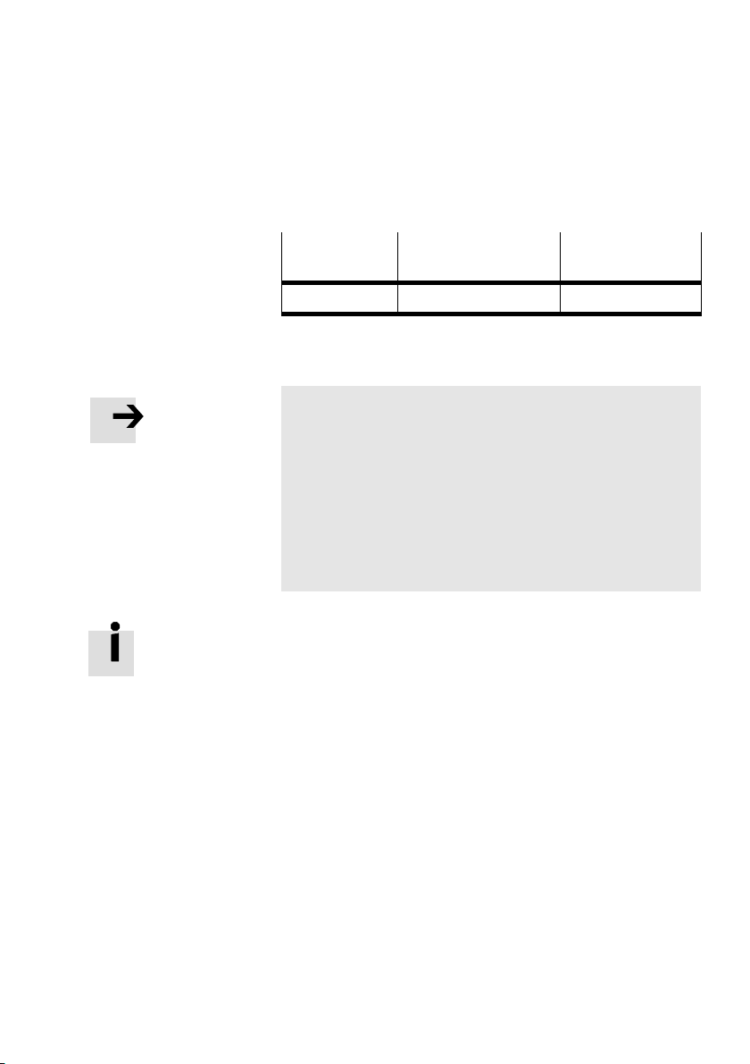
The following station numbers are permitted:
Protocol
Address designation Permitted station
numbers
PROFIBUS−DP Station number 1; ...; 125
Tab.1/1:Permitted station numbers
Please note
The station number (DP slave address) of the valve ter
minal cannot be modified by the DP master. The valve ter
minal can only b
e addressed by the station number set on
the rotary/DIL switches.
Station numbers may only be assigned once per field bus
module/PROFIBUS−DPinter
face.
Observe any possible limitations as regards the assign
ment of station addresses by your DP master.
Recommendation:
Assign the station numbers in
ascending order. If necessary,
assign the station numbers to suit the machine structure of
your system.
Festo P. BE−CP−FB13−E−EN en 0802h
1−7
Page 20

1. Installation
Setting the voltage monitoring
With switch element 2 of the DIL switch, you can specify
whether or not the load voltage of the valves and the output
modules is
to be monitored (see chapter 3 Diagnosis and
fault treatment").
DIL switch
Voltage monitoring
active
DIL 2: ON DIL 2: OFF
Voltage monitoring
inactive
Tab.1/2:Setting the voltage monitoring, DIL switch
element 2
Reserved DIL switch elements 3...6
Leave switch elements 3...6 set as follows:
DIL switch
Setting reserved
1−8
DIL 3...5: ON
DIL 6: OFF
Tab.1/3: Reserved DIL switch elements 3...6
Festo P. BE−CP−FB13−E−EN en 0802h
Page 21

1. Installation
1.3 Connecting the field bus
1.3.1 Field bus cable
Please note
With incorrect installation and high baud rates, data trans
mission faults may occur as a result of signal reflections
and attenuation
Causes of the transmission faults may be:
missing or incorrect terminating resistor
incorrect screening/shield connection
branches
transmission over
unsuitable cables.
Observe the cable specifications. Refer to the manual for
your controller for information on the type of cable to be
used.
s.
long distances
Festo P. BE−CP−FB13−E−EN en 0802h
Please note
If the CP system is fitted onto the moving part of a ma
chine, the field bus cable on the moving part must be pro
vided wi
tions in I EC/DIN EN 60204−1.
th strain relief. Please observe the relevant regula
1−9
Page 22

1. Installation
Use a twisted, screened 2−wire cable for the field bus.
Cable specification as per EN 50170 (cable type A):
Surge impedance: 135...165 ohms (3...20 MHz)
Capacitance
per unit length:< 30 nF/km
Loop resistance:< 110 ohms/km
Core diameter: > 0.64 mm
Core cross−sectional area:> 0.34 mm
2
Bus length Exact specifications on the bus length can be found in the
next section and in the manuals for your control system.
1−10
Festo P. BE−CP−FB13−E−EN en 0802h
Page 23

1. Installation
1.3.2 Field bus baud rate and field bus length
Please note
The maximum permitted field bus length and branch line
length depend on the baud rate used.
· Please observe the maximum permitted length of the
field bus cable if you connect the CP system via a branch
line.
· Take into account also the sum of the branch line lengths
when calculating the maximum permitted length of the
field bus cable.
Field bus node FB13 sets
itself automatically to one of the
following baud rates:
Baud rate
(inkBaud)
9.6 1200 m 500 m
19.2 1200 m 500 m
93.75 1200 m 100 m
187.5 1000 m 33.3 m
500 400 m 20 m
1500 200 m 6.6 m
3000...12000 100 m
Field bus length
(max.)
Max. permitted
branch line length
Tab.1/4: Max. field bus length and branch line length for
PROFIBUS−DP depending on the baud rate
Festo P. BE−CP−FB13−E−EN en 0802h
1−11
Page 24
1. Installation
1.3.3 Field bus interface
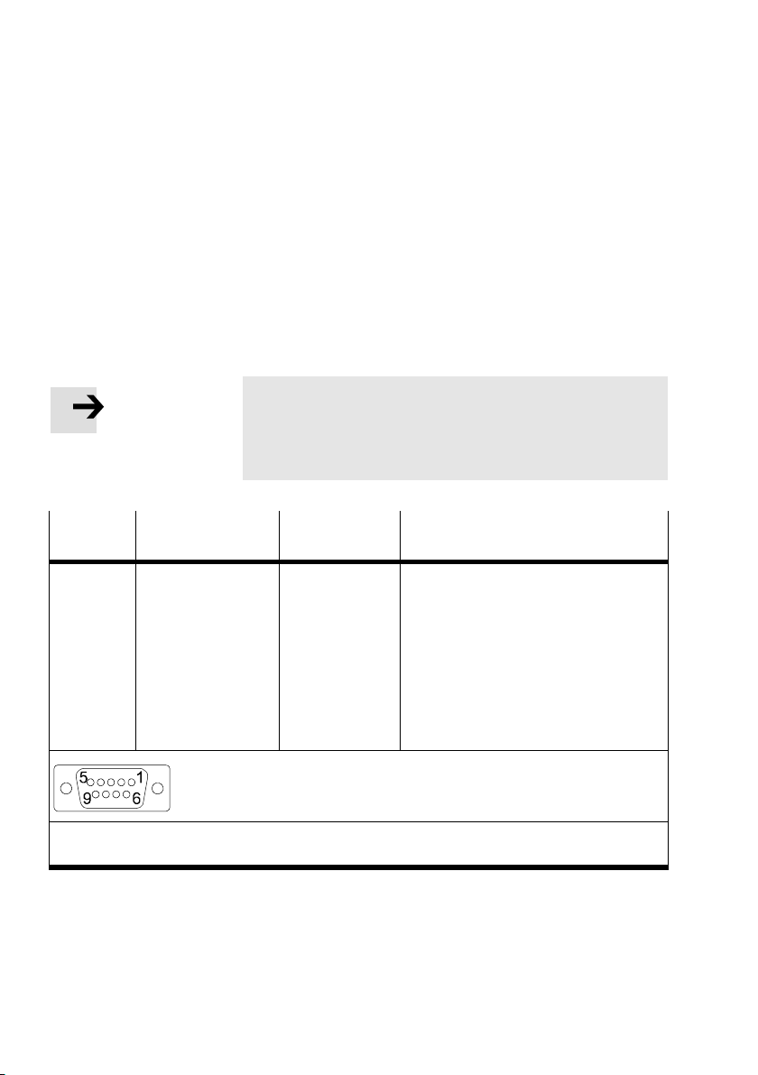
There is a 9−pin sub−D socket on the node for connecting the
valve terminal to the field bus.
This connection is used for the incoming cable
the continuing field bus cable. You can connect the valve
terminal with the field bus plug from Festo
typeFBS−SUB−9−GS−DP−B.
as well as for
Please note
Only the Festo field bus plug complies with IP65. Before
connecting field bus plugs from other manufacturers:
· replace the two flat screws by bolts (part no. 340960).
Pin
1
2
3
4
5
6
7
8
9
Housing
Field bus plug
IP65 from Festo
B
A
Clamp strap
PROFIBUS−DP Designation
1)
n.c.
n.c.
RxD/TxD−P
2)
CNTR−P
DGND
VP
n.c.
RxD/TxD−N
n.c.
Screening/shield
(view of socket on field bus node)
1)
Typ e FBS−SUB−9−GS−DP−B (part no. 532216)
2)
Repeater control signal CNTR−P is in the form of a TTL signal.
Tab.1/5:Pin assignment of the field bus interface
1−12
Not connected
Not connected
Receive/send data P
Repeater control signal
Data reference potential (M5V)
Power supply positive (P5V)
Not connected
Receive/send data N
Not connected
Connection to functional earth
Festo P. BE−CP−FB13−E−EN en 0802h
2)
Page 25

1. Installation
1.3.4 Connection possibilities
Please note
Use a protective cap or blanking plug to seal unused con
nections. You will then comply with protection class I P65.
Connection with field bus plugs from Festo
· Observe the fitting instructions for the field bus plug.
You can connect the valve terminal to the field bus easily with
the field bus plug fro
partno.532216). You can disconnect the plug from the node
without interrupting the bus cable (T−TAP function).
m Festo (type FBS−SUB−9−GS−DP−B,
1 Hinged cover with
display window
213
2 Blanking plug if
connection is not
used
3 Clamp strap for
screening/shield
connection
4 Field bus
incoming (IN)
5 Switch for bus
termination and
continuing field
bus
6 Field bus
continuing (OUT)
7 Only connected
capacitively
Fig.1/3:Field bus plug from Festo type FBS−SUB−9−GS−DP−B
Festo P. BE−CP−FB13−E−EN en 0802h
Bus out
AB AB
ON
567
Bus in
4
1−13
Page 26

1. Installation
Please note
The clamp strap in the field bus plug from Festo is con
nected internally only capacitively with the metallic hous
ing of the sub−D p
lug. This is to prevent equalizing currents
flowing through the screening of the field bus cable.
DIL switch With the switch in the field bus p
following:
Switch position OFF: The bus termination is switched off
and the continuing field bus cable is switched in.
Switch
position ON: The bus termination is switched on
and the continuing field bus cable is switched off
(seeFig.1/4).
Please note
Note the type designation of your field bus plug. The new
plug type FBS−SUB−9−GS−DP−B switches the continuing
field bus cable off when the bus termi
on.
lug you can switch the
nation is switched
1−14
Festo P. BE−CP−FB13−E−EN en 0802h
Page 27

1. Installation
Connection with M12 adapter (reverse key coded)
With adapter (type: FBA−2−M12−5POL−RK, part no. 533118),
you can connect the valve terminal to the field bus via an M12
plug connector. The
anical coding (reverse key or B−coded), to avoid confusion
between incoming and continuing connections.
You can disconnect the M12 adapter from the node without
interrupting the bus cable (T−TAP function).
plug connectors have an inverted mech
Connection to the field bus is made wi
th a 5−pin M12 plug
with PG9 screw connector. Use the second connection socket
for the continuation of the field bus.
M12 adapter (reverse key coded)
2
3
4
Bus in
151
5
2
3
4
Bus out
Pin no.
1. VP: Power supply positive (P5V)
2. RxD/TxD−N: Receive/Send data N
3. DGND: Data reference potential (M5V)
4. RxD/TxD−P: Receive/Send data P
5.FE: Functional earth
Housing/thread: Screening/shield
Protective cap or plug with bus
termination resistor if connection
is not used.
Tab.1/6:Pin assignment of the field bus interface with adapter for M12 connection,
5−pin
Festo P. BE−CP−FB13−E−EN en 0802h
1−15
Page 28

1. Installation
Connection with optical−fibre waveguide
The PRO FIBUS−DP interface of the node complies with specifi
cation EN 50170−2 and supports the control of network com
ponents for optical fibre wavegui
Use optical−fibre waveguides when transmission is affected
by heavy interference, as well as for extending the trans
mission range when high baud
Example of optical−fibre waveguide network components:
Siemens Optical Link Module (OLM) for PRO FIBUS plus
des.
rates are used.
Siemens Optical Li
Harting Han−InduNet
nk Plug (OLP) for PROFIB US (I P20)
®
Media converter IP65 in combina
tion with adapter cable for Festo products (optical data
transmission in DESINA installation concept)
1−16
Festo P. BE−CP−FB13−E−EN en 0802h
Page 29
1. Installation
1.4 Bus termination with terminating resistors
Please note
If the CP system is at the beginning or end of the field bus
system, a bus termination will be required.
· Fit a bus termination to both ends of a bus segment.
Recommendation:
Use the ready−to−use field bus plugs from Festo for the bus
termination.
housing of this plug (see Fig.1/4).
A suitable resistor network is incorporated in the
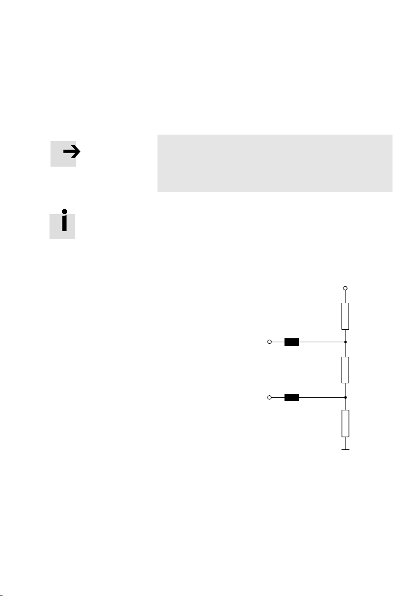
Pin 6: Power supply
390
Festo P. BE−CP−FB13−E−EN en 0802h
Receive/send data P
(data cable B)
120 nH
Pin 3
220
Receive/send data N
(data cable A)
Pin 8
120 nH
390
Pin 5: Data reference potential
Fig.1/4: Circuit diagram for bus connection network for
cable type A as per EN 50170 (switch in Festo field
bus plug set to ON)
1−17
Page 30

1. Installation
1.5 Connecting the CP modules
Warning
· For connecting the CP modules to a string, use the
special CP cable from Festo (type KVI−CP−1−...).
· Please note that the total length of cable on a string
must not exceed 10 m.
You can thereby avoid:
faults in data exchange between the
node and the con
nected CP modules.
Information on the connection procedure can be found in the
manual Installing and commissioning CP system
s."
1−18
Festo P. BE−CP−FB13−E−EN en 0802h
Page 31

1. Installation
1.6 Connecting the power supply
Please note
Use a suitable power unit to supply the CP field bus node
separately with operating voltage.
Information on the procedure as
well as on connecting cables
and current requirements can be found in the manual Instal
ling and commissioning CP systems."
Warning
· Use only PELV circuits as per IEC/DIN EN 60204−1 (Pro
tective Extra−Low Voltage, PELV) for the electrical supply.
Consider also the general requirements for PELV circuits
in accordance with IEC/DIN EN 60204−1.
· Use power supplies which guarantee reliable electrical
isolation of the operating voltage as per IEC/DIN EN
60204−1.
By the use of PELV circuits, protection
against electric shock
(protection against direct and indirect contact) is guaranteed
in accordance with IEC/EN 60204−1 (Electrical equipment for
machines,
General requirements).
Please note
Check within the framework of your EMERGENCY STOP
circuit, to ascertain the measures necessary for putting
your machine/system into a safe state
in the event of an
EMERGENCY STOP (e.g. switching off the operating voltage
for the valves and output modules, switching off the com
pressed air).
Festo P. BE−CP−FB13−E−EN en 0802h
1−19
Page 32

1. Installation
1−20
Festo P. BE−CP−FB13−E−EN en 0802h
Page 33

Commissioning
Chapter 2
2−1Festo P. BE−CP−FB13−E−EN en 0802h
Page 34

2. Commissioning
Contents
2. Commissioning 2−1 . . . . . . . . . . . . . . . . . . . . . . . . . . . . . . . . . . . . . . . . . . . . . . . .
2.1
2.2Device master file (GSD) and icon files 2−12 . . . . . . . . . .
2.3Configuration with a Siemens master 2−13 . . . . . . . . . . . . . .
Preparing the CP system for commissioning 2−3 . . . . . . . . . . . . . . . . . . . . . . . . .
2.1.1 Saving the stri
2.1.2Information on commissioning 2−5 . . .
2.3.1 STEP 7 HW Config (up to V 5.2) 2−14 . . . . . . . . . . . . . . . .
2.3.2 Examples of addressing 2−20 . . . . . . . . . . . . . . . . . . . . . . . . . . . . . .
2.3.3Commissioning the CP system on the PROFIB US−DP 2−24 . . . . . . . . . . .
ng assignment 2−3 . . . . . . . . . . . . . . . . . . . . . . . . . . . . . .
. . . . . . . . . . . . . . . . . . . . . . . . . .
. . . . . . . . . . . . . . . . . . . .
. . . . . . . . . . . . . . . . .
. . . . . . . . . . .
. . . .
2−2
Festo P. BE−CP−FB13−E−EN en 0802h
Page 35

2. Commissioning
2.1 Preparing the CP system for commissioning
Warning
Before commissioning:
· Make sure that the setting of switch elements 3...6 on
the DIL switch is correct (see section 1.2.1).
During operation:
· Do not modify the settings of the DIL switch.
You will thereby avoid undesired movements of the con
nected actuators.
2.1.1 Saving the string assignment
Please note
Before commissioning the CP system
· Prepare the CP system for commissioning (see manual
Installing and commissioning CP systems").
Festo P. BE−CP−FB13−E−EN en 0802h
Prepare commissioning of the CP system on the
PROFIBUS−
DP as follows:
1. Connect the power supply of the node (see manual
Installing and commissioning CP systems").
2. Connect the CP modules.
itch on the power supply.
3.Sw
4. Save the current string assignment by pressing the
SAVEbutton.
2−3
Page 36
2. Commissioning
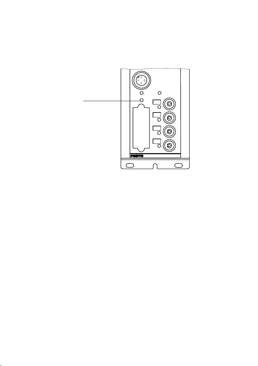
1 SAVE button
24VDC
POWER
SAVE
1
POWERV
0
1
2
3
ERROR
Fig.2/1:The SAVE button saves the current string assignment of the CP system as the
NOMINAL configuration
2−4
Festo P. BE−CP−FB13−E−EN en 0802h
Page 37

2. Commissioning
2.1.2Information on commissioning
FREEZE and SYNC
The operating modes FREEZE and SYNC are supported by the
CP system in accordance with EN 50170.
The method of accessing the commands FREEZE and SYN
depends on the controller used. Please refer here to the
documentation for your field bus module.
Caution
The operating modes FREEZE or SYNC will be reset auto
matically if:
the CP system is switched on/off
the field bus module stops.
he operating mode FREEZE will be reset automati
Only t
cally if:
the bus connection to the CP system is interrupted
(response monitoring activ
FREEZE command
All the inputs of the CP system will be frozen." The CP sys
tem now constantly sends an image of all the inputs to the
aster. With each further FR EEZE command, the input image
m
is updated and sent again constantly to the master.
Return to normal operation: UNFREEZE
SYNC command
All the outputs of the CP system will be frozen." The CP sys
tem now no longer reacts to modifications to the output
ge in the master. With each further SYNC command, the
ima
updated output image will be transmitted.
Return to normal operation: UNFREEZE command
e).
command
C
Festo P. BE−CP−FB13−E−EN en 0802h
2−5
Page 38

2. Commissioning
Module consistency
The CP system supports the following variants of module
consistency:
over the complete structure of the CP system
over the selected format
(byte).
Sequence of configuration entries
Caution
The number of inputs/outputs must correspond to the
equipment fitted on the CP system. The configuring of
additional inputs and outputs as a later
permitted.
reserve is not
Configuration with DP identifiers
Please note
DP identifier 049 or 16DX (standard mode) is used for the
examples.
The configuration data must be known or ascertained for
each bus slave
CP system:
standard mode
compact mode
. There are two possibilities of configuring the
2−6
The CP system recognises automatically the mode in
you wish to operate the CP system, on the basis of the DP
identifier sent by the master.
Festo P. BE−CP−FB13−E−EN en 0802h
which
Page 39

2. Commissioning
Caution
Configure a CP system only in one of these two ways:
standard mode (max. 4 x 049)
compact mode (sum identifiers).
The identifiers
must not be mixed.
Bit
Bit
7654 3210
*)
Not supported
Fig.2/2: Structure of the identifier byte
Long data
00 = 1 byte/word
...
15 = 16 bytes/words
Input/output
00 = specific identifier formats
01 = entry
10 = output
11 = input/output
Length
0 = byte
1 =word
Consistency
0 = byte or word
1 = complete length
*)
Festo P. BE−CP−FB13−E−EN en 0802h
Example:
00010000
= 016d (010h): 8DI = 8 digital inputs
b
2−7
Page 40
2. Commissioning
Standard mode
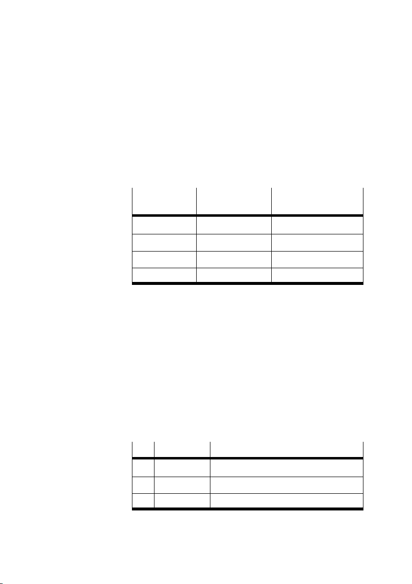
Configure in standard mode 16 outputs and 16 inputs per as
signed string. DP identifier: 049 or 16DX for each assigned
string.
The following table shows
for the valve terminal in standard mode:
an overview of the possible entries
Last used
string number
0 2 16DX
1 4 16DX, 16DX
2 6 16DX, 16DX, 16DX
3 8 16DX, 16DX, 16DX, 16DX
Number of bytes
for input/outputs
Individual identifier
Tab.2/1:Standard mode: possible configuration of the
inputs and outputs
The last used string is decisive for the number of DP ident
ifiers, even if numericall
y lower strings are not assigned
physically (see manual Installing and commissioning
CPsystems").
Example:
CP system with 3 strings, a total of
3 input modules and
3output modules, highest assigned string number = 2.
DP identifier Comment
0 16DX Input module and output module of string 0
2−8
1 16DX Input module and output module of string 1
2 16DX Input module and output module of string 2
Tab.2/2:Example of configuration in standard mode
Festo P. BE−CP−FB13−E−EN en 0802h
Page 41

2. Commissioning
Compact mode
In compact mode configure the sum of the input bytes and
the sum of the output bytes separately and independently
of each other (see Tab.2/3). The following applies here:
Please note
Observe the sequence inputs before outputs" in
compactmode, if both inputs and outputs areinstalled
in a CPsystem.
CP valve terminals occupy
two output bytes irrespective of
the number of valve coils.
Assign the DP identifiers in ascending order without gaps.
No field must remain unused (input
s before outputs).
If only output modules or CP valve terminals are fitted:
enter their DP identifiers in line 0.
The string assigned with t
he highest number of inputs or
outputs defines the sum of input or output bytes.
Non−existent CP valve terminals occupy input or output
bytes if a higher string is assi
gned with inputs or outputs.
Maximum configuration in compact mode:
023
039d8 input bytes and 8 output bytes
d
Festo P. BE−CP−FB13−E−EN en 0802h
2−9
Page 42
2. Commissioning
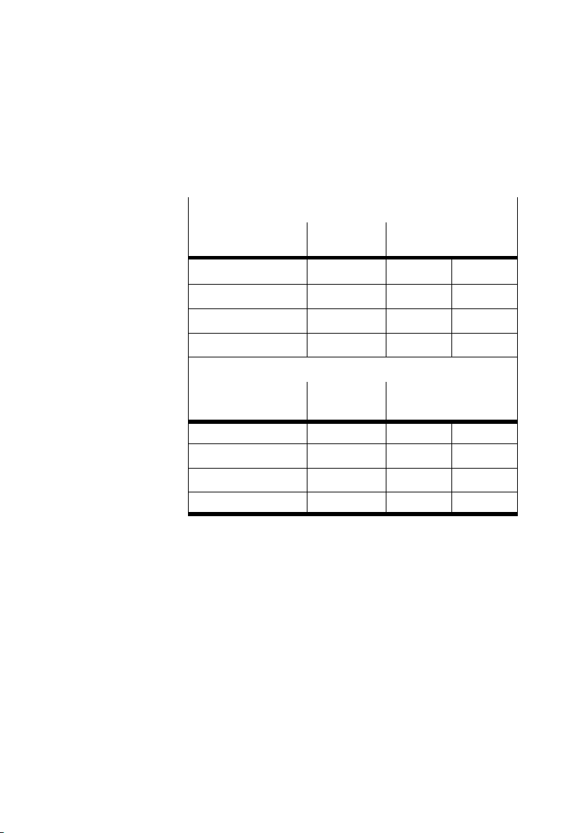
The following table shows an overview of the possible entries
for the valve terminal in compact mode.
With input modules
Last used string
number
Number of
input bytes
Sum identifier (decimal)
0 2 017
1 4 019
2 6 021
3 8 023
d
d
d
d
16DI
32DI
With output modules or valve terminals
Last used string
number
0 2 033
1 4 035
2 6 037
3 8 039
Number of
output bytes
Sum identifier (decimal)
d
d
d
d
16DO
32DO
Tab.2/3: Compact mode: possible configuration of the
inputs and outputs
2−10
Festo P. BE−CP−FB13−E−EN en 0802h
Page 43

2. Commissioning
Example 1:
CP system with 3 strings, a total of 3 input modules and
3output modules, highest assigned string number = 2.
DP identifier Comment
0 021
1 037
d
d
6 bytes inputs
6 bytes outputs
Example 2:
CP system with 3 strings, only 3 output modules, highest
assigned string number = 2.
DP identifier Comment
0 037
d
6 bytes outputs
Festo P. BE−CP−FB13−E−EN en 0802h
2−11
Page 44

2. Commissioning
2.2 Device master file (GSD) and icon files
In order to configure the valve terminal with a PC/pro
grammer, you will require the appropriate GSD file. In addi
tion to slave−typical
the device master file (GSD) also contains a selection of ident
ifiers.
entries (Ident. number, Revision, etc.),
Reference sources Current GSD files can be found on the
under:
www.festo.com/fieldbus
You can obtain the GSD files and further configuration aids
with the CD ROM Utilities" from Festo:
type P.CD−VI−UTILITIES−2, part no. 533500
The most up−to−date GSD files are always available via the
Internet.
GSD files You will require one of the
following files for the CP field bus
node 13:
VI10F13C.GSD (German version) or
VI10F13C.GSE (International version)
Icon files In order to represent the CP sy
stem in your configuration
software, you will find icon files under the above−mentioned
Internet address:
Normal operating
Diagnostic case Special operating
status
Festo Internet pages
status
2−12
File: Pbfb13en.dib File: Pbfb13ed.dib File: Pbfb13cs.dib
Tab.2/4: Icon files for configuration software
Festo P. BE−CP−FB13−E−EN en 0802h
Page 45

2. Commissioning
2.3 Configuration with a Siemens master
Please note
Various configuration programs are available for use in
conjunction with a Siemens master. Please observe the
relevant procedure for your co
The following sections describe as an example the main con
figuration steps with the STEP7 software. It is assumed that
reader is already familiar with the information in the man
the
ual for the STEP7 software.
Information on operation with general DP mas
found in appendix A.2.
Before commissioning or programming, compile a configur
ation list of all connected field bus slaves. On the basis of this
list you can:
nfiguration program.
ters can be
Festo P. BE−CP−FB13−E−EN en 0802h
carry out a comparison between the NOMINAL and the
ACTUAL configurations to ascertain if there are any con
nection faults.
access t
hese specifications during the syntax check of a
program, in order to avoid addressing faults.
The configuration of the CP system requires a very
accurate
procedure, as different configuration specifications are some
times required for each system, due to the modular structure.
Please observe her
e the specifications in the following sec
tions.
2−13
Page 46

2. Commissioning
2.3.1 STEP 7 HW Config (up to V 5.2)
Preparations
GSD1. Copy the GSD of the valve terminal into the directory
...\STEP7\S7DATA\GSD on your PC/programmer.
File: VI10F13C.GS*
(Reference sources for the GSD see sectio
The GSDs can be either:
copied manually into the above mentioned directory
(e.g. with Windows Explorer) or
n 2.2)
loaded via the menu
Please note
Update the hardware catalogue if you copy the GSD during
work with STEP 7.
Menu HW Config: [Options] [Update catalogue]
Please note
As from STEP 7 V4.02, GSDs are stored within the STEP7
project (station GSD). This can cause the updating/reading
of new GSD files to appea
yourself about handling the station GSD files in the STEP7
help.
[Options] [Install new GSD].
r as if incorrect. Please inform
2−14
Festo P. BE−CP−FB13−E−EN en 0802h
Page 47

2. Commissioning
2.Process the dialogue window Properties PROFIB US"
Baud rate
Profile
Icons3. Copy the icon files (see section 2.2) for the CPX terminal
into directory ...\STEP7\S7DATA\NS
BMP on your PC or
programmer.
The icon files can either be copied
manually into the above named directory or
loaded via the menu [Option
s] [Install new GSD]
file type Bitmap files" in HW Config."
4. Insert a DP master system:
Right−hand mouse click on DP" under CPU" i
rack.
Click on [Add master system] in the context menu.
The line of the DP master system will be displayed.
n the
Festo P. BE−CP−FB13−E−EN en 0802h
2−15
Page 48

2. Commissioning
Station selection with STEP 7
1. If the hardware catalogue is not open: click on the cata
logue icon (see Fig.2/3 1).
The hardware catalogue will be displayed.
2. Open the
following folder in the hardware catalogue:
\PROFIBUS−DP\AdditionalFieldDevices\Valves."
The folder VALVES is displayed when you copy the GSD
(see step 1 of the
preparations).
Pull the station type FESTO CP FB13" onto the line of the
DP master system 2.
The dialogue window Properties PROFIBUS i
nterface"
will be displayed 3.
3.Select the PROFIBUS address identical to the selected
setting on the DIL/rotary switch in the node (see section
1) and confirm this with OK.
1.2.
The dialogue window Properties DP slave" appears 4.
4. Process the dialogue window, if necessary, and close it.
The icon of the
valve terminal will be displayed on the line
of the DP master system.
2−16
Festo P. BE−CP−FB13−E−EN en 0802h
Page 49

2. Commissioning
12
34
Fig.2/3:Station selection with STEP 7 HW Config
(the windows displayed are not all visible at the same time, see text)
Festo P. BE−CP−FB13−E−EN en 0802h
2−17
Page 50

2. Commissioning
Configuration with STEP 7
You can configure the CP system in standard mode" or in
compact mode." Assign the configuration table as follows:
Modifying the address
1. Click on the icon
of the valve terminal to be configured in
Hardware config. (see Fig.2/4 1). The configuration
table will be displayed under the rack 2.
Open the module F ESTO CP FB13" (folder\PROFIBUS−
2.
DP\Additional Field Devices\Valves\...) in the hardware
catalogue 3.
3. Configuration in standard mode
Pull the module corresponding
to the highest assigned
string number of your CP system onto location 0 in the
configuration table.
Assign the starting address in the window Pr
operties
DP slave" 4.
Configuration in compact mode
Pull the Universal module" onto location 0 in the con
figuration table (see Fig.2/5).
Select the I/O type,
the starting address and the number
of I or O−bytes in the window Properties DP slave."
Information on this can be found in Tab.2/3. Repeat
last steps for further modules.
· Double click the appropriate line in the configuration
table and modify the starting address of the inputs or
outputs in the window Properties D
P slave."
the
2−18
Please note
With S7−400 controllers, up to 4 bytes of addresses are
reserved for each DP identifier depending on the version
status.
Festo P. BE−CP−FB13−E−EN en 0802h
Page 51

2. Commissioning
12 3
4
Fig.2/4: Configuration in standard mode with STEP 7 HW Config
Fig.2/5: Configuration in compact mode with STEP 7 HW Config
Festo P. BE−CP−FB13−E−EN en 0802h
2−19
Page 52

2. Commissioning
2.3.2 Examples of addressing
Example 1: Standard mode
String assignment
of the CPsystem
String 0:
16 outputs and
16 electrical inputs
String 1:
not assigned
String 2:
16 outputs and
16 electrical inputs
String 3:
not assigned
DP
I/O address (IN/OUT)
identifier
049
049 (O22.0...23.7, (unused)
049
Address range can be
O20.0...21.7
I20.0...21.7
(I22.0...23.7, (unused)
O24.0...25.7
I24.0...25.7
used for other bus slaves
Tab.2/5: Addressing the CP system shown in Fig.2/6
2−20
Festo P. BE−CP−FB13−E−EN en 0802h
Page 53

2. Commissioning
Octet 1, bits 0...7: O20.0...O20.7
Octet 2, bits 0...7: (O21.0...O21.7)
BUS ERROR
POWER
SAVE
PROFIBUS−DP
24 V DC
ERROR
POWERV
0
1
2
3
Octet 3, bits 0...7: (O22.0...O22.7)
Octet 4, bits 0...7: (O23.0...O23.7)
Octet 5: Bits 0...7 O24.0...O24.7
Octet 6: Bits 0...7 (O25.0...O25.7)
Octet 1, bits 0...7: I20.0...I20.7
Octet 2, bits 0...7: I0...I21.7
Octet 3, bits 0...7: (I22.0...I22.7)
Octet 4, bits 0...7: (I23.0...I23.7)
Octet 5: Bits 0...7 I24.0...I24.7
Octet 6: Bits 0...7 I25.0...I25.7
I = Input
O = Output
( )= Assigned, but not used
Fig.2/6:Examples of addressing the inputs and outputs of a CP system on the
PROFIBUS−DP in standard mode
Festo P. BE−CP−FB13−E−EN en 0802h
2−21
Page 54

2. Commissioning
Example 2: Compact mode
String assignment
of the CP system
String 0:
8 outputs
String 1:
16 inputs
String 2:
16 outputs
String 3: not assigned Address range can be
DP
identifier
017
037
I/O address
(IN/OUT)
O20.0...21.7
(I20.0...21.7, unused)
(O22.0...23.7, unused)
I22.0...23.7
O24.0...25.7
used for other bus slaves
Tab.2/6: Addressing the CP system shown in Fig.2/7
2−22
Festo P. BE−CP−FB13−E−EN en 0802h
Page 55

2. Commissioning
Addresses of the CP system: 12
Octet 1, bits 0...7: O20.0...O20.7
Octet 2, bits 0...7: (O21.0...O21.7)
PROFIBUS−DP
BUS ERROR
POWER
SAVE
24 V DC
POWERV
0
1
2
3
ERROR
Octet 3, bits 0...7: (O22.0...O22.7)
Octet 4, bits 0...7: (O23.0...O23.7)
Octet 5, bits 0...7: O24.0...O24.7
Octet 6, bits 0...7: O25.0...O25.7
I = Input
I = Output
( )= Assigned, but not used
Sum of the assigned bytes: 6 output bytes; 4 input bytes
Octet 1, bits 0...7: (I20.0...I20.7)
Octet 2, bits 0...7: (I21.0...I21.7)
Octet 3, bits 0...7: I22.0...I22.7
Octet 4, bits 0...7: I23.0...I23.7
No further input bytes assigned
Fig.2/7: Addressing the inputs and outputs of a CP system on the PROFIBUS−DP in
compact mode
Festo P. BE−CP−FB13−E−EN en 0802h
2−23
Page 56
2. Commissioning
2.3.3Commissioning the CP system on the PROFIBUS−DP
Please note
Please observe also the switching−on instructions in the
manual for your controller.
Proceed as follows:
1. Connect the field bus cable to the field bus no
de.
2.Switch on the operating voltages:
of all field bus slaves
of the CP system.
3.Switch on the operating voltage for the master m
odule.
Configuration run When the system is switched on, some master systems
automatically carry out a comparison between the NOMINAL
and the A
CTUAL configurations. For this configuration run it
is important that:
the specifications for the NOMINAL configuration are com
plete and correct (see
also section 2.1.1).
the power supply for the programmable logic controller
and for the field bus slaves is switched on eithersimulta
neously or
in the sequence indicated above.
2−24
Festo P. BE−CP−FB13−E−EN en 0802h
Page 57

2. Commissioning
Recommendation:
Providing the safety concept of your machine/system permits
this, commission the CP system with both operating voltages
(pin
s 1 and 2), but without compressed air. A suitable test
function is therefore available which does not trigger unde
sired reactions.
Please note
A CP valve location occupies two addresses. The following
assignment applies:
lower−value address:pilot solenoid 14
higher−value address:pilot solenoid 12
Festo P. BE−CP−FB13−E−EN en 0802h
2−25
Page 58

2. Commissioning
2−26
Festo P. BE−CP−FB13−E−EN en 0802h
Page 59

Diagnosis and error treatment
Chapter 3
3−1Festo P. BE−CP−FB13−E−EN en 0802h
Page 60

3. Diagnosis and error treatment
Contents
3. Diagnosis and error treatment 3−1 . . . . . . . . . . . . . . . . . . . . . . . . . . . . . . . . . . . .
3.1 LED displays on the bus
3.1.1 Normal operating
3.1.2 Fault display of the POWE R
3.1.3 Fault messages of the LED BUS ERROR 3−6 . . . . .
3.2 Testing the valves 3−7 . . . . . . . . . . . . . . . . . . . . . . . .
3.3 Diagnosis via PROFIBUS−DP 3−9 . . . . . . . . . . . . . . . . . .
3.3.1 Diagnostic words3−9 . . . . . . . . . . . . . . . . . . . . . .
3.3.2 Diagnostic steps3−10 . . . . . . . . . . . . . . . . . . . . . . . .
3.3.3Overview of diagnostic bytes 3−11 . . . . . . . . . . . . . . . . . . . . . .
3.3.4 Details for standard diagnostic information 3−12 . . . . . . . . . . . . . . . . . .
3.4 Fault treatme
3.4.1 Siemens SIMATIC S5/S73−18 . . . . . . . . . . . . . . . . . . . . . . . . . . . . . . . . . .
3.5Online d
3.5.1 Read diagnost
3.6 Short circuit/overload 3−22 . . . . . . . . . .
3.6.1Output module 3−22 . . . . . . . . . . .
3.6.2Input module 3−24 . . . . . . . . . . . . .
nt 3−17 . . . . . . . . . . . . . . . . . . . . . . . . . . . . . . . . . . . . . . . . . . . . . . . . .
iagnosis with STEP 73−20 . . . . . . . . . . . . . . . . . . . . . . . . . . . . . . . . . . . . .
node3−3 . . . . . . . . . . . . . . . . . . . . . . . . . . . . . . . . . . . . .
status3−4 . . . . . . . . . . . . . . . . . . . . . . . . . . . . . . . . . .
LEDs 3−5 . . . . . . . . . . . . . . . . . . . . . . . . . . .
. . . . . . . . . . . . . . . . . . . . . . .
ic buffer with STEP 7 (up to V 5.2) 3−20 . . . . . . . . . . . . . .
. . . . . . . . . . . . . . . . . . . . . . . . . . . . . . . . .
. . . . . . . . . . . . . . . . . . . . . . . . . . . . . .
. . . . . . . . . . . . . . . . . . . . . . . . . . . . . .
. . . . . . . . . . . . . . . . .
. . . . . . . . . . . . . . . . . . . .
. . . . . . . . . . . . . . . . . .
. . . . . . . . . . . . . . . .
. . . . . . . .
3−2
Festo P. BE−CP−FB13−E−EN en 0802h
Page 61

3. Diagnosis and error treatment
3.1 LED displays on the bus node
The LEDs on the node enable a speedy on−the−spot diagnosis
to be made of the operating status of the CP system.
1 LED BUS ERROR
2 LED POWER
3 LED POWER V
4 String fault LEDs
1
2
Fig.3/1:LEDs of CP field bus node FB13
PROFIBUS−DP
BUSERROR
24VDC
POWER
SAVE
0
1
2
3
ERROR
POWERV
3
4
Festo P. BE−CP−FB13−E−EN en 0802h
3−3
Page 62

3. Diagnosis and error treatment
LED designation Function Meaning
BUS ERROR Bus communication Flashes when there is a fault in conjunction
POWER Operating voltage display
of internal electronics
POWER V Load voltage display for
valves
0...3 CP string LED In the starting phase:
with the field bus or when there is an address
fault.
Lights up when the operating voltage is
applied to pin 1; the node is ready to operate.
Lights up when the load voltage of the valves
is OK (pin 2);
flashes if load voltage < 20.4 V and >10 V
Flashes if the string assignment has been
modified since the previous operation.
During operation:
Lights up if a CP connection is interrupted
Tab.3/1: Overview of the function of the LEDs of the field bus node
3.1.1 Normal operating status
In the normal operating status only the green LEDs POWER
and POWER V light up.
lights up LED flashes out
LED
Colour Operating status Fault treatment
BUS Out Normal None
POWER Green
lights up
POWER V Green
lights up
Normal None
Normal None
Tab.3/2:Normal operating status
3−4
Festo P. BE−CP−FB13−E−EN en 0802h
Page 63

3. Diagnosis and error treatment
3.1.2 Fault display of the POWER LEDs
LED Colour Operating status Fault treatment
POWER
POWER V
POWER
POWER V
POWER
POWER V
POWER
Green
lights up
Operating status normal
or
Operating status normal, but
valves do not switch.
Compressed air supply not OK
Pilot exhaust blocked
or
Operating status normal, but
PROFIBUS fault message of the
LED BUS ERROR
Green
lights up
Load voltage of the outputs
(pin2) not applied.
or
CP valve terminal or output
Out
Green
lights up
module defective.
Load voltage of the outputs
(pin2) not in the tolerance range.
Green
flashes
Out Operating voltage of the
electronics (pin1) not applied.
or
Hardware fault
None
Check the ...
· Compressed air supply
· Pilot exhaust channels
See fault messages of the LED
BUS ERROR
· Check load voltage of the
outputs (pin2)
· Replace the CP module
· Check load voltage of the
outputs (pin2).
· Check the operating voltage
connection
Servicing required
Festo P. BE−CP−FB13−E−EN en 0802h
3−5
Page 64

3. Diagnosis and error treatment
3.1.3 Fault messages of the LED BUS ERROR
Possible PROFIBUS−specific LED displays of the operating
status of the CP node are shown in the following table:
LED
BUS
ERROR
BUS
ERROR
BUS
ERROR
Colour Operating status Fault treatment
Red
flashes fast
Red
flashes slowly
(1−second
intervals)
Out Valve test
Station number not permitted · Correct station number
Field bus connection not OK.
Possible causes:
Station number not correct
(e.g. address assigned twice)
Field bus module switched off
or defective
Interrupted, short−circuited or
faulty field bus connection
Configuration not correct:
nominal š actual status
(1; ...; 125)
Check the ...
· Setting of the address selector
switch
· Field bus module
· Field bus connection
· Configuration
(Conclude valve test)
3−6
Festo P. BE−CP−FB13−E−EN en 0802h
Page 65
3. Diagnosis and error treatment
3.2 Testing the valves
Warning
Before the test:
· Switch off the compressed air supp ly for the valves.
· In the case of a non−saved string assignment:
Save the current string assignment with the SAVE key
(see section 2.1.1).
You can then avoid undesired
or dangerous movements of
the actuators.
Caution
This test function runs automatically in the CP terminals.
All valves are switched on/off cyclically.
None of the programmed lockings or further swi
tching
conditions will be taken into account.
Test routineDuring the test routine of the CP terminal all the valves are
switched on/off at 1−
second intervals.
Festo P. BE−CP−FB13−E−EN en 0802h
3−7
Page 66

3. Diagnosis and error treatment
Starting the test routine
1.Switch off the power supplies (pins 1 and 2) on the node.
2.Switch off the load voltage supply to the output modules.
3. Remove the cover
4. Note the setting of the rotary and DIL switch elements.
5.Set station number 199.
6.Switch on the power supplies
7.Starting the test routine: Set DIL switch element 1 to OFF.
If faults occur when the test routine is started, the r
the node will flash quickly. The procedure must then be re
peated.
of the rotary/DIL switches.
(pins 1 and 2).
ed LED on
Concluding the test routine
1.Switch off the power supplies (pins 1 and 2) on the node.
2.Set the address selector switch and the DIL switch
elements to their origin
When the test routine is finished, switch on the power sup
plies again:
on the node
on the output modules.
al positions again.
3−8
Festo P. BE−CP−FB13−E−EN en 0802h
Page 67
3. Diagnosis and error treatment
3.3 Diagnosis via PROFIBUS−DP
The CP system supports diagnostic possibilities via the
PROFIBUS as per EN 50170. The device−specific diagnosis is
supported.
Please note
The identifier−related or channel−related diagnosis listed in
EN 50170 is not supported.
3.3.1 Diagnostic words
The following fault states of the CP system are grouped into
diagnostic words and passed on to the controller:
Festo P. BE−CP−FB13−E−EN en 0802h
Load voltage failure on the o
Short circuit/overload at the output modules
Interruption of the CP connection on various CP modules
Additional fault messages when DIL s
Load voltage failure in the CP connection
Lower voltage tolerance limit of CP valves exceeded
(t20.4 V)
utput modules
witch element 2 = ON:
3−9
Page 68

3. Diagnosis and error treatment
Busy bit
With device−related diagnosis 1, the CP system supplies
status information as bit 1:
3.3.2 Diagnostic steps
Busy bit = CP system in starting phase and t
herefore not
ready for date exchange
If the busy bit is set (= log. 1"), the diagnostic bits in
bytes2...5 contain log. 0." Only device−relat
ed diagnosis 1 is
supported.
The CP system offers extensive diagnostic possibilities via the
PROFIBUS−DP. The diagram below shows you the steps re
quired for diagnosing t
he CP system. Only the diagnostic bits,
which require a further diagnostic step, are represented.
12304567 Bit
1
Device−related
diagnosis 1 sensible
Device−related
diagnosis 2...5 can be read
Station status 1
12304567
Bit
1
Device−related diagnosis 1
3−10
Fig.3/2: Diagnostic steps
Festo P. BE−CP−FB13−E−EN en 0802h
Page 69

3. Diagnosis and error treatment
3.3.3Overview of diagnostic bytes
Diagnostic words Several diagnostic words are provided for each bus slave.
The diagnostic words and their meaning for CP systems
from Fes
to are shown in the following table:
*
Byte
0 1 Station status 1 Station status 2 2 1
2 3 Station status 3 Master address
4 5 Manufacturer identifier
6 7 Header Device−related diagnosis 1
8 9 Device−related diagnosis 2
10 11 Device−related diagnosis 4
12 13 Device−related diagnosis 6
bold = Contents modified by the CP system
*=Siemens
** = EN 50170
Octet**Diagnostic address Diagnostic address + 1 Octet**Byte
4 3
6 5
8 7
10 9
12 11
14 13
(Ident_number
High byte F1h)
(fault byte CP string 0)
(fault byte CP string 2)
(not used)
(Diag. master_Add)
Manufacturer identifier
(Ident_number
Low byte 3Ch)
(overview of faults)
Device−related diagnosis 3
(fault byte CP string 1)
Device−related diagnosis 5
(fault byte CP string 3)
Device−related diagnosis 7
(not used)
Tab.3/3: Diagnostic words
*
Festo P. BE−CP−FB13−E−EN en 0802h
3−11
Page 70

3. Diagnosis and error treatment
3.3.4 Details for standard diagnostic information
The following diagnostic information can be requested by the
DP master from the CP system via the function Slave_Diag.
The CP system replies with an octet string of length 15. The
procedure for reading out this diagnostic information with a
SIMATIC S5/S7 system is described in
Octet 1: Station status_1
Bit Meaning Explanation
chapter 3.4.2.
0 Diag.Station_Non_Existent CP system no longer/not yet addressable.
1 Diag.Station_Not_Ready CP system not yet ready for data exchange
2 Diag.Cfg_Fault The configuration data received from the master do not
3 Diag.Ext_Diag There is a device−related diagnosis. Possible causes:
4 Diag.Not_Supported 1 = CP system does not support the function requested
5 Diag.Invalid_Slave_Response Always 0 (set by CP system)
6 Diag.Prm_Fault Last parametrizing telegram faulty
7 Diag.Master_Lock Always 0 (set by CP system)
bold = Valve terminal related bits
Possible causes:
Operating voltage not applied
Data cable interrupted
Fault in data cable
agree with those ascertained by the CP system.
Cable fracture on input/output module
Short circuit/overload at electric outputs or sensor
supply for inputs
V
V
V
t20.4 V
valves
outputs
t10 V
sensor
t10 V
Tab.3/4: Diagnostic bits station status 1
3−12
Festo P. BE−CP−FB13−E−EN en 0802h
Page 71

3. Diagnosis and error treatment
Octet 2: Station status_2
Bit Meaning Explanation
0 Diag.Prm_Req 1 =The master must configure the CP system again
1 Diag.Stat_Diag 1 =The master must request diagnostic data until this
2 Always 1 (set by CP system)
3 Diag.WD_On 1 = Response monitoring/watchdog activated
4 Diag.Freeze_Mode 1 =FREEZE activated
5 Diag.Sync_Mode 1 =SYNC activated
6 Reserved
7 Diag.Deactivated Always 0 (set by CP system)
bold = Valve terminal related bits
bit is set to 0
Tab.3/5: Diagnostic bits of station status 2
Octet 3: Station status_3
Bit Meaning Explanation
0...6 Reserved
7 Diag.Ext_Diag_Overflow Always 0 (set by CP system)
Tab.3/6: Diagnostic bits of station status 3
Festo P. BE−CP−FB13−E−EN en 0802h
3−13
Page 72

3. Diagnosis and error treatment
Further octets
Octets 4...7: Overview
Octet Designation Explanation
4 Diag.Master_Add Master address:
5...6 Ident_number Manufacturer identification:
7 Ext_Diag_Data
(device−related diagnosis)
The address of the master, which parametrized the
CP system, is entered in this octet.
These octets contain the manufacturer identification:
F13Ch for the Festo CP system.
Header device−related diagnosis:
The CP system enters the fixed value 8 in this octet,
i.e. 8 Octets Device−related diagnosis" incl. the
header octet, are made available/transferred, irre
spective of the equipment fitted on the CP system.
6 of the 8 octets are used.
Tab.3/7: Overview of octets 4...7
3−14
Festo P. BE−CP−FB13−E−EN en 0802h
Page 73

3. Diagnosis and error treatment
Structure of device−related diagnosis
Octet 8: Device−related diagnosis 1
Bit Meaning Explanation
0 Common fault in CP system 1 =Fault in one or several CP strings (bits 4...7)
1 Busy bit 1 = During the starting phase: CP system not yet ready
2 Not used
3 Not used
4 Common fault 0 1 =Fault in string 0
5 Common fault 1 1 =Fault in string 1
6 Common fault 2 1 =Fault in string 2
7 Common fault 3 1 =Fault in string 3
for data exchange
Tab.3/8: Diagnostic bits of device−related diagnosis 1
Festo P. BE−CP−FB13−E−EN en 0802h
3−15
Page 74

3. Diagnosis and error treatment
Overview octets 9...12: Device−related diagnosis 2...5
Octet Explanation
9 Device−related diagnosis 2: String 0
10 Device−related diagnosis 3: String 1
11 Device−related diagnosis 4: String 2
12 Device−related diagnosis 5: String 3
Tab.3/9: Overview of device−related diagnosis 2...5
Octets 9..12: Device−related diagnosis 2...5
Bit Meaning Explanation
0 Error
1 Error
Output
Input
1 = CP connection interrupted at output module
1 = CP connection interrupted at input module
2 Short circuit/overload 1 =Short circuit/overload at the output module
3 V
4 V
5 V
6 V
off
sen
val
load
*)
*)
1 =Load voltage failure at output module
1 =Short circuit/overload in sensor supply t10 V
1 *)= Load voltage of valve coils t20.4 V
1 *)= Load voltage of valve coils t10 V
7 Ex Not used
*)
Only with setting DI L switch element 2 at ON
Tab.3/10: Diagnostic bits device−related diagnosis 2...5
3−16
Festo P. BE−CP−FB13−E−EN en 0802h
Page 75

3. Diagnosis and error treatment
3.4 Fault treatment
With the following faults, the behaviour of the CP system de
pends on the configured behaviour of the master module:
telegram failure
master
stopped
interruption in the bus cable.
Depending on the setting or configuration, all the outputs
(valves and electric outputs) will be switched off or
retain
their status.
Warning
· Make sure that valves and outputs are put into a safe
state when the faults named occur.
An incorrect status of the valves and outputs may
lead to
dangerous situations.
Please note
Please observe the following if the outputs are reset in the
event of a PLC stop, field bus interruption or field bus fault:
Single−solenoid valves m
ove to the basic position.
Double−solenoid valves remain in the current position.
Mid−position valves move to the mid−position (depend
ing on valv
e type: pressurized, exhausted or blocked).
Festo P. BE−CP−FB13−E−EN en 0802h
3−17
Page 76

3. Diagnosis and error treatment
3.4.1 Siemens SIMATIC S5/S7
With these controllers, you can determine the reaction of the
CP system to the faults named above.
Almost all configuration programs
Response monitoring." For the operating modes named, the
time specified corresponds to the drop−off time of the valves
and electric outputs.
There are two ways in which you can set the control system to
react to faults:
hard fault reaction: When a fault
switches to the operating mode STOP."
soft fault reaction: When a fault occurs the controller
remains in the operating m
Control system
SIMATIC S5 with
IM308C
SIMATIC S7/M7 OM82 Reaction to a device−specific
Module Meaning STOP RUN
OM23 Reaction to QVZ with direct
periphery access
OM24 Reaction to QVZ with periphery
access via process image
OM35 Reaction to PEU
(periphery not clear)
diagnosis
OM86 Reaction to failure of a DP slave Default OM is
contain the function
occurs the controller
ode RUN."
Default OM is
programmed
Default OM is
programmed
Default OM is
programmed
Default OM is
programmed
programmed
QVZ: Quitting delay; OM: Organisation module; PEU: Periphery not clear
Tab.3/11:Fault reactions STOP and RUN with S5/S7
Further details can be found in the relevant controller
manuals.
3−18
Festo P. BE−CP−FB13−E−EN en 0802h
Page 77

3. Diagnosis and error treatment
Possibilities for reading out the diagnosis for S5/S7
The diagnosis for PROFIBUS−DP is supported in the various
control systems by means of function modules. These read
out the slave diagnosis and writ
user program.
e it into a data range of the
Control system
SIMATIC S5 with
IM 308C
SIMATIC S5 with
S5−95U/DP master
SIMATIC S5 with
SF 50/DP master
SIMATIC S7/M7 SFC 13 DP NRM_DG" Reference manual System
Function module See ... Manufacturer
FB 192 IM 308C" Manual ET 200 decentral
periphery system"
FB 230 S_DIAG" Manual ET 200 decentral
periphery system"
FB 230 S_DIAG" Manual Programmable valve
terminal with SB/SF 50"
functions and standard
functions"
Siemens
Siemens
Festo
Siemens
Tab.3/12:Possibilities for reading out the diagnosis for S5/S7
Example for a STEP 7 user program
STL Explanation
CALL SFC 13 Reading request
REQ:=TRUE
LADDR:=W#16#03FE Pointer at diagnostic address, e.g. 1022d = 03FEh
RET_VAL:=MW100 If fault occurs, output fault code
RECORD:=P#M110.0 WORD 7 Pointer at start of data range for diagnosis and length of
BUSY:=M10.0 Reading concluded
(see mask Properties DP slave" in HW Config)
diagnostic data
Festo P. BE−CP−FB13−E−EN en 0802h
3−19
Page 78

3. Diagnosis and error treatment
3.5 Online diagnosis with STEP 7
Direct diagnostic events in conjunction with the Festo valve
terminal can be:
Decentral periphery: station failure
Communication between slave and
Faulty component (see device−specific diagnosis)
Transition of the operating status from START to RUN
(nominal/actual differen
The configuration data of the valve terminal do not
agree with the periphery.
Valve terminal has incorrect DIL/rotary switch
ce exists)
3.5.1 Read diagnostic buffer with STEP 7 (up to V 5.2)
The diagnostic buffer of STEP 7 offers the possibility of dis
playing diagnostic events of the S7 systemin the sequence in
which they occur.
master interrupted
setting.
3−20
Prerequisit
HW Config has been accessed.
Proceed as follows (Fig.3/3):
1.Switch from offline to online 1.
2. Click with the right−hand mouse button on the CPU i
3. Click on [Component status...] in the context menu which
4. Click on
5. Click on the event and read the details. These supply
es:
n the
rack 2.
now appears. The window Component status" will be
shown 3.
the register Diagnostic Buffer" 4.
more detailed information on the further procedure
depend on the S7 controller 5 used.
Festo P. BE−CP−FB13−E−EN en 0802h
and
Page 79

3. Diagnosis and error treatment
21
3
4
6
Fig.3/3: Online diagnosis via diagnostic buffer (explanation see text)
5
Device−related diagnosis
· Instead of the CPU, click on the CP valve terminal 6.
Read further information on the device−related diagnosis
of the CP system via the
Festo P. BE−CP−FB13−E−EN en 0802h
window Component status."
3−21
Page 80

3. Diagnosis and error treatment
3.6 Short circuit/overload
Detailed information on input and output modules can be
found in the manual CP modules electronics."
3.6.1Output module
In the event of a short circuit or overload:
all the digital outputs of a string will be switched off.
the green LED Diag" on the output modu
quickly.
the short circuit/overload bit in the octets 9...12 Device−
related diagnosis 2...5" will be set to 1.
Please note
The outputs cannot be used again until the short circuit or
overload has been eliminated and the fault deleted.
le will flash
3−22
Festo P. BE−CP−FB13−E−EN en 0802h
Page 81

3. Diagnosis and error treatment
logical 0 (RESET) or
p
y
Deleting the fault
You can delete the fault by resetting all eight outputs. You
can do this in one of the following ways:
Possibilities
· Set all the outputs of the output module to
logical 0" (RESET) or
· Briefly interrupt the CP connection at the
CPoutput module or
· Briefly interrupt the operating voltage for the
CP system
Tab.3/13: Deleting the fault possibilities
The outputs can then be used again. If the short circuit/over
load still exists, the outputs will be sw
Explanation
Manually or automatically in the program
Outputs on the output module will be reset
automatically
All outputs of the CP system will be reset
automatically
itched off again.
Festo P. BE−CP−FB13−E−EN en 0802h
3−23
Page 82

3. Diagnosis and error treatment
3.6.2Input module
If there is a short circuit, overload or voltage fault in the
sensor supply:
the sensor supply for all inputs of the module will be
the green LED Diag" on the input module will flash
switched
quickly.
off.
the fault bit V
in the octets 9−12 Device−related
sen
diagnosis 2...5" will be set to 1.
Please note
The inputs cannot be used again until the short circuit or
overload has been eliminated and the fault deleted.
Deleting the fault
You can delete the fault in one of the following ways:
briefly interrupt the CP connection at the CP input module
or
briefly interrupt the operati
at the field bus node.
The inputs can then be scanned again. If the short circuit/
overload still exists, t
he fault will be shown again.
Module CP−E16−M8−Z:
The short circuit/overload will be reset automatically and the
voltage will be switched on again.
ng voltage for the CP system
3−24
Festo P. BE−CP−FB13−E−EN en 0802h
Page 83

Technical appendix
Appendix A
A−1Festo P. BE−CP−FB13−E−E N en 0802h
Page 84

A. Technical appendix
Contents
A. Technical appendix A−1 . . . . . . . . . . . . . . . . . . . . . . . . . . . . . . . . . . . . . . . . . . . . .
A.1 Technical
A.2Commissioning with the general DP masterA−5
A.2.1Bus start A−5 . . . . . . . . . . . . . . . . . .
A.2.2 Send parametriziung data A−6 . . . . . . . .
A.2.3 Check the configuration data A−7 . . . . . . . . . . . . . .
A.2.4 Transferring input and output data A−9 . . . . . . . . . . . . . . . . . . . . . .
A.2.5 Read diagnostic informationA−11 . . . . . . . . . . . . . . . . . . . . . . . . . . . . . . .
A.2.6Implemente
A.2.7Bus parameters/reaction timesA−12 . . . . . . . . . . . . . .
A.2.8 Transmission times on the PROFIBUS−DPA−12 . . . . . . . . . . . . . . . . . . . .
specifications Field bus node CP FB13−E A−3 . . . . . . . . . . . . . . . . . . . .
. . . . . . . . . . . . . . . . . . . . . . . . . .
. . . . . . . . . . . . . . . . . . . . . . . . . . . . .
. . . . . . . . . . . . . . . . . . . . . . . .
. . . . . . . . . . . . . . . .
. . .
d functions and service access points (SAP) A−11 . . . . . . . .
. . . . . . . . . . . . . .
A−2
Festo P. BE−CP−FB13−E−EN en 0802h
Page 85

A. Technical appendix
A.1 Technical specifications Field bus node CP FB13−E
General information
Temperature range
Operation
Storage/transport
Relative humidity 95 %, non−condensing
− 5 ... + 50 °C
− 20 ... + 70 °C
Protection class as per EN 60529 plug connector
inserted or provided with protective cap
Protection against electric shock
(protection against direct and indirect contact as
per IEC/DIN EN 60204−1)
Electromagnetic compatibility
Interference emitted
Resistance to interference
*)
The CP system is intended for industrial usage.
IP65
by means of PELV circuits
(ProtectiveExtra−Low Voltage)
Tested as per EN 61000−6−4 (industry)
Tested as per EN 61000−6−2 (industry)
Operating voltage for the electronics and the input modules
Pin 1
Power supply connection
Rated value
Tolerance
Current consumption
Pin 1 node FB13−E
Complete electronics of the CP system
Residual ripple 4 Vpp (within tolerance)
Bridging time during drop in logic voltage 20 ms
24 V DC
20.4 ... 26.4 V
250 mA
See manual CP system," current consumption
table
*)
Festo P. BE−CP−FB13−E−EN en 0802h
A−3
Page 86

A. Technical appendix
Load voltage for solenoid valves of CP valve terminal
Pin 2
Power supply connection
Rated value
Tolerance
Current consumption
Pin 2 node FB13−E Sum of all switched−on CP solenoid valves;
Residual ripple 4 Vpp (within tolerance)
Bridging time during drop in logic voltage 20 ms
24 V DC
20.4 ... 26.4 V
see manual CP pneumatics"
Field bus
Protocol PROFIBUS−DP as per EN 50170
Design RS 485, floating
Transmission type Serial asynchronous, half−duplex
Baud rate 9.6...12000kBaud,
Cable type Depending on cable length and baud rate:
A−4
automatic baud rate recognition
see controller manual
Festo P. BE−CP−FB13−E−EN en 0802h
Page 87

A. Technical appendix
A.2 Commissioning with the general DP master
The Festo CP system can be controlled from any PLC, PC or
industrial PC with a PROFIB US−DP modulein accordance with
EN 50170.
Further informatio
A.2.1Bus start
n Read the information on the following themes in the
appropriate sections:
Module consistency, FREEZE and SYNC, identifiers:
Section 2.1.2
GSD: S
In order to commission the CP system correctly, the DP master
must carry out the following functions in the sequence speci
fied:
1.Send param
2. Check the configuration data
3.Transfer input and output data (cyclic data exchange)
4. Read diagnostic information
The composition and
described in the following sections.
ection 2.2
etrizing data
contents of the individual tele grams are
Festo P. BE−CP−FB13−E−EN en 0802h
A−5
Page 88

A. Technical appendix
A.2.2 Send parametriziung data
Set_Prm The parametrizing data are transferred from the DP master
to the valve terminal with the function Set_Prm.
Octet 1: Station status
Bit Meaning Explanation
0 Reserved
1
2
3 WD_On Response monitoring of the CP system on/off:
4 Freeze_Req 0 = FREEZE mode not requested by the master
5 Sync_Req 0 = SYNC mode not requested by the master
6 Unlock_Req Bit 7 Bit 6 Explanation
7 Lock_Req 0 0 min T
0 = off
1 = on
1 = FREEZE mode set by the master
1 = SYNC mode set by the master
+ slave parameter may be overwritten
SDR
0 1 CP system released for other masters
1 0 CP system blocked for other masters
1 1 CP system released for other masters
Tab.A/1: Octet 1: Station status
A−6
Festo P. BE−CP−FB13−E−EN en 0802h
Page 89
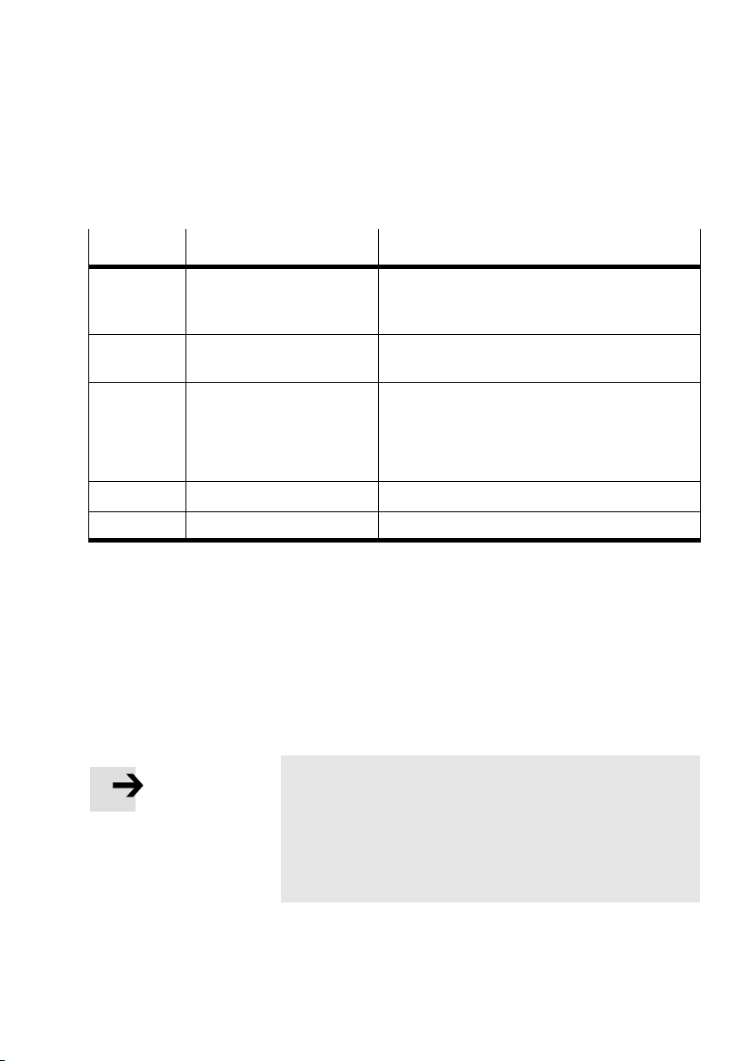
A. Technical appendix
Further octets
Octet Designation Explanation
2 and 3 WD_Fact_1
4 Minimum station delay
5 and 6 Ident_number Transmission of the manufacturer identifier of the
7 Group_Ident Not supported by the CP system
8...32 User_Prm_Data Not supported by the CP system
WD_Fact_2
responder (min T
SDR
)
Range 1...255: The response monitoring time of the
CP system is transferred with these two octets:
TWD [s] = 10 ms x WD_Fact_1 x WD_Fact_2
The minimum time the CP system must wait, before
the reply telegram may be sent to the DP master.
CPV Direct (= F13Ch); parametrizing telegrams to
the CP system are only accepted if the transmitted
and the programmed manufacturer identifiers are
the same.
Tab.A/2: Octets 2...32
A.2.3 Check the configuration data
Chk_CfgThe configuration data are transferred from the DP master
to the CP system with the function Chk_Cfg.
Please note
The configuration of the CP system must be carried out as
follows:
per string: a DP identifier for inputs and outputs
via sum identifier: sum of
output bytes.
the input bytes and sum of the
Festo P. BE−CP−FB13−E−EN en 0802h
The composition of the identifier bytes can be found in
section 2.1.2.
A−7
Page 90

A. Technical appendix
Summary of parameters (Chk_Cfg):
Octet 1−n: DP identifier
Permitted identifiers for CP systems from Festo in
compact mode (see also Tab.2/
3):
Number of
Decimal inputs Decimal outputs
I/Os
up to 16 017 033
up to 32 019 035
up to 48 021 037
up to 64 023 039
Tab.A/3: Overview of DP identifiers for the CP system
Example:
Configuration: Function: Chk_Cfg
String
Octet DP identifier
decimal hex
0 1 049 031
1 2 049 031
Tab.A/4: Configuring a CP system with 32 inputs/outputs
in standard mode
A−8
Festo P. BE−CP−FB13−E−EN en 0802h
Page 91

A. Technical appendix
A.2.4 Transferring input and output data
Data_Exchange The cyclic exchange of data is accomplished with the func
tion Data_Exchange.
With this function the output data for CP systems is tr
ans
mitted as an octet string of length x. The octet string length
depends on the number of identifier bytes.
Please note
With the function Data_Exchange, the CP system expects
the output data for the valves and electric outputs.
The input data is sent to the master as a
reply telegram.
Festo P. BE−CP−FB13−E−EN en 0802h
A−9
Page 92

A. Technical appendix
Overview of parameters (Data_Exchange):
Octet 1: I/O data byte_0
Bit 0: Input/output x
Bit 1: Input/output x+1
. . .
Bit 7: Input/output x+7
Octet 2: I/O data byte_1
Bit 0: Input/output x+8
Bit 1: Input/output x+9
. . .
Bit 7: Input/output x+15
Octet 3:
I/O data byte_2
Bit 0: Input/output y
Bit 1: Input/output y+1
. . .
Bit 7: Input/output y+7
. . .
Octet 5: I/O data byte_4
Bit 0: Input/output z
Bit 1: Input/output z+1
. . .
Bit 7: Input/output z+7
. . .
*)
*)
*)
A−10
Octet 8: I/O data byte_7
Bit 0: Input/output t+8
Bit 1: Input/output t+9
. . .
Bit 7: Input/output t+15
*)
x, y, z, t = Address offset of the master module
Festo P. BE−CP−FB13−E−EN en 0802h
Page 93

A. Technical appendix
A.2.5 Read diagnostic information
Slave_DiagThe diagnostic data are requested by the CP system via the
function Slave_Diag (see section 3.3, Diagnosis via PROFI
BUS−DP).
Set_Prm Wi
th the function Set_Prm you have the possibility of deter
mining the watchdog time (WD_Fact_1, Octet 2, WD_Fact_2,
Octet 3). In the e
vent of a fault, the CP system will switch off
all the valves and electric outputs after the parametrized
time (e.g. if there is a bus failure).
A.2.6Implemented functions and service access points (SAP)
Function Available Destination SAP
Data_Exchange Yes NIL
RD_Inp Yes 56
RD_Outp Yes 57
Slave_Diag Yes 60
Set_Prm Yes 61
Chk_Cfg Yes 62
Get_Cfg Yes 59
Global_Control Yes 58
Set_Slave_Add No 55
(DSAP)
Festo P. BE−CP−FB13−E−EN en 0802h
Tab.A/5: Overview of implemented functions and service
access points
A−11
Page 94

A. Technical appendix
11
A.2.7Bus parameters/reaction times
Baud rate
max T
(kBaud)
... 187.5 60
500 100
1500 150
3000 250
6000 450
12000 800
Tab.A/6: Bus parameters and reaction times
A.2.8 Transmission times on the PROFIBUS−DP
The time delay within the CP system depends on the amount
of data and therefore on the extension to the CP system. It
amounts
Please refer to the manual for your controller for ascertaining
the total time required for transmission.
to: < 2 ms.
Please note
Observe here the cycle time of your PLC and the update
time of the PROFIBUS−DP.
SDR
(T
) min T
Bit
11
SDR
(T
Bit
)
A−12
Festo P. BE−CP−FB13−E−EN en 0802h
Page 95

Index
Appendix B
B−1Festo P. BE−CP−FB13−E−E N en 0802h
Page 96

B. Index
B. Index B−1 . . . . . . . . . . . . . . . . . . . . . . . . . . . . . . . . . . . . . . . . . . . . . . . . . . . . . . . . .
B.1Index B−3 . . . . . . . . . . . . . . . . . . . . . . . . . . . . . . . . . . . . . .
. . . . . . . . . . . . . . . . . . .
B−2
Festo P. BE−CP−FB13−E−EN en 0802h
Page 97

B. Index
A
Abbreviations, Product−specific X . . . . . . . . . . . . . . . . . . . . .
B
Baud rate 1−11 . . . . . . . . . . . . . . . . . . . . . . . . . . . . . . . . . . . . .
Branch line lengths 1
BUS ERROR LED 3−6 . . . . . . . . . . . . . .
Bus termination 1−17 . . . . . . . . . . . . . . . . . . . . . .
Busy bit 3−10 . . . . . . . . . . . . . . . . . . . . . . . . . . . . . . . . . .
. . . . . . . . . . . . . . . . . . .
. . . . . . . . . .
. . . . .
C
Cable, Field bus 1−9 . . . . . . . . . . . . . . . . . . . . . . . . . . . . . . . . .
Check the configuration data
Compact mode 2−9 . . . . . . . . . . . . . . . . . . . . .
Configuration run 2−24 . . . . . . . . . . . . . . . . . . . . . . . . . . . . .
Connecting
CP modules 1−18 . . . . . . . . . . . . . . . . . . . . . . . . . . . . . . . . . .
Field bus 1−9 .
Power supply 1−19 . . . . . .
Connection for optical−fibre waveguide 1−16 . . . . . . . . .
Connections, Field bus 1−12 . . . . . . . . . . . . . . . . . . . . . . . . . . .
CP system, Preparing fo
Cyclic exchange of data A−9 . . . . . . . . . . . . . . . . . . . . . . . . . . .
. . . . . . . . . . . . . . . . . . . . . . . . . . . . . . . . . . . .
. . . . . . . . . . . . . . . . . . . . . . . . . .
r operation on the PROFIBUS−DP 2−3
. . . . . . . . . . . . .
. .
. . . .
−11 . . . . . . . . . . . . . . . . . . . . . . . . . . . . .
A−7 . . . . . . . . . . . . . . . . . . . . . .
Festo P. BE−CP−FB13−E−EN en 0802h
D
Designated use V . . . . . . . . . . . . . . . . . . . . . . . . . . . . . . . . . . .
Device master file (GSD) 2−12
Device−related diagnosis 3−15 . . . . . . . . . . . . . . . .
Device−related diagnosis 2...5 3−16 . . . . . . . . . . . . . . . . . . . . .
. . . . . . . . .
B−3
. . . . . . . . . . . . . . . . . . . . . . . . .
Page 98

B. Index
Diagnosis
BUS ERROR LED 3−6 . . . . . . . . . . . . . . . . . . . . . . . . . . . . . . .
POWER LEDs 3−5 . . . . . .
Siemens master 3−9 . . . . . . . . . . . . . .
Diagnostic bytes 3−11 . . . . . . . . . . . . . . . . . . . . . . . . . . .
Diagnostic steps 3−10 . . . . . . . . . . . . . . . . . . . . . . . . . . . . . . . .
Diagnostic words
Overview 3−11 . . . . . . . . . . . .
DIL switch 1−6 . . . . . . . . . . . . . . . . . . . .
. . . . . . . . . . . . . . . . . . . . . . . . . . . .
. . . . . . . . . . . . . . . . .
. . . . .
3−9 . . . . . . . . . . . . . . . . . . . . . . . . . . . . . . . .
. . . . . . . . . . . . . . . . . . . . . . . .
. . . . . . . . . . . . . . . . . .
E
Examples of addressing 2−20 . . . . . . . . . . . . . . . . . . . . . . . . . .
F
Fault treatment 3−17 . . . . . . . . . . . . . . . . . . . . . . . . . . . . . . . . .
Field bus baud rate 1−11
Field bus cable 1−9 . . . . . . . . . . . . . .
Field bus interface 1−12 . . . . . . . . . . . . . . . . . . . . . .
Field bus length 1−11 . . . . . . . . . . . . . . . . . . . . . . . . . . . . . . . .
Field bus
FREEZ E 2−5 . . . . . . . .
plug 1−13 . . . . . . . . . . . . . . . . . . . . . . . . . . . . . . . . . .
. . . . . . . . . . . . . . . . . . . . . . . . . . . . . . . .
. . . . . . . . . . . . . . . . . . . .
. . . . . . . .
. . . . . . . . . . . . . . . . . . . . . . . . . . . . .
B−4
G
General DP master A−5 . . . . . . . . . . . . . . . . . . . . . . . . . . . . . . .
I
Identifiers 2−6 . . . . . . . . . . . . . . . . . . . . . . . . . . . . . . . . . . . . . .
Implemented funct
Important user instructions VII . . . . . . . . .
ions A−11 . . . . . . . . . . . . . . . . . . . . . . . . . .
. . . . . . . . . . . . . . .
L
LEDs 3−3 . . . . . . . . . . . . . . . . . . . . . . . . . . . . . . . . . . . . . . . . . .
Festo P. BE−CP−FB13−E−EN en 0802h
Page 99

B. Index
M
M12 adapter 1−15 . . . . . . . . . . . . . . . . . . . . . . . . . . . . . . . . . . .
N
Notes on the use of this manual VI . . . . . . . . . . . . . . . . . . . . .
O
Octets 4...7, Overview 3−14 . . . . . . . . . . . . . . . . . . . . . . . . . . .
Operating status 3−4 . . . .
. . . . . . . . . . . . . . . . . . . . . . . . . . . .
P
Pictograms VIII . . . . . . . . . . . . . . . . . . . . . . . . . . . . . . . . . . . . .
Pin assignment, Field bus
POWER LEDs 3−5 . . . . . . . . . . . . . . . . . . . . . . .
Power supply
Connecting 1−19 . . . . . . . . . . . . . . . . . . . . . . . . . . .
Power unit 1−19 . . . . . . . . . . . . . . . . . . . . . . . . . . . . . . . . . . .
P
ower unit 1−19 . . . . . . . . . . . . . . . . . . . . . . . . . . . . . . . . . . . .
PROFIBUS−DP
Diagnostic in
STEP 7 2−14 . . . . . . . . . . . . . . . .
formation 3−12 . . . . . . . . . . . . . . . . . . . . . . . . .
interface 1−12 . . . . . . . . . . . . . . . .
. . . . . . . . . . . . .
. . . . . . .
. . . . . . . . . . . . . . . . . . . . . .
Festo P. BE−CP−FB13−E−EN en 0802h
R
Reaction times A−12 . . . . . . . . . . . . . . . . . . . . . . . . . . . . . . . . .
Reverse key 1−15 . . . .
Rotary switch 1−6 . . . . . . . . . . . .
. . . . . . . . . . . . . . . . . . . . . . . . . . . . . . .
. . . . . . . . . . . . . . . . . . . . . . .
S
SAVE button 2−4 . . . . . . . . . . . . . . . . . . . . . . . . . . . . . . . . . . . .
B−5
Page 100

B. Index
Send parametrizing data A−6 . . . . . . . . . . . . . . . . . . . . . . . . . .
Service VI . . . . . . . . .
Service access points (SAP) A−11 . . . . . . . . . .
Setting
Station number 1−6 . . . . . . . . . . . . . . . . . . . . . . . . . . . . .
Voltage monitoring 1−8 . . . . . . . . . . . . . . . . . . . . . . . . . . . . .
Setting the address 1−
Setting the station number 1−6 . . . . . . . .
Short circuit, Short circuit/overload 3−22 . . . . . . . . . . . . . . . .
ns master, Configuration 2−13 . . . . . . . . . . . . . . . . . . . .
Sieme
Standard mode 2−8 . . . . . . . . . . . .
Station status 3−12 . . . . . . . . . . . . . . . . . . . . .
STEP 7, Online diagnosis 3−20 . . . . . . . . . . . . . . . . . . . . . . . . .
relief 1−9 . . . . . . . . . . . . . . . . . . . . . . . . . . . . . . . . . . . . .
Strain
String assignment, Saving 2−3 .
Icon files 2−12 . . . . . . . . . . . . . . . . . . . . . .
SYNC 2−5 . . . . . . . . . . . . . . . . . . . . . . . . . . . . . . .
. . . . . . . . . . . . . . . . . . . . . . . . . . . . . . . .
. . . . . . . . . . . .
. . .
. . . . . . . . . . . . . . . .
. . . . . . . . . . . . . . . . . . . . . .
. . . . . . . . . . . . .
. . . . . . . . . . . . . . . . . . . . . . . .
. . . . . . . . . . . . . . . .
. . . . . . . . . . .
6 . . . . . . . . . . . . . . . . . . . . . . . . . . . . . .
B−6
T
Target group VI . . . . . . . . . . . . . . . . . . . . . . . . . . . . . . . . . . . . .
Technical specifications A−
Testing the valves 3−7 . . . . . . . . . . . . . .
Text markings VIII . . . . . . . . . . . . . . . . . . . . . . . . .
. . . . . . . . . . . . . . . . . .
. . . . . . . . . .
Festo P. BE−CP−FB13−E−EN en 0802h
3 . . . . . . . . . . . . . . . . . . . . . . . . . . .
 Loading...