

Page 1
Compact performance
Programming
and diagnostics
manual
CP field bus node 11
TypeCP−FB11−E
Field bus protocol:
− DeviceNet
Manual
165 211
en 0802d
[730 616]
Page 2

Page 3

Contents and general instructions
Original de. . . . . . . . . . . . . . . . . . . . . . . . . . . . . . . . . . . . . . .
Edition en 0802d. . .
DesignationP.BE−CP−FB11−E−EN. . . . . . . . . . . . . .
. . . . . . . . . . . . . . . . . . . . . . . . . . . . . . .
. . . . . . . .
Order no. 165 211. . . . . . . . . . . . . . . . . . . . . . . . . . . . . . . . .
E(Festo AG&Co.
KG, D73726 Esslingen, Federal Republic of
Germany, 2008)
Internet: http://www.festo.com
e−mail:service_international@festo.com
The copying, distribution and utilization of this document
as
well as the communication of its contents to others without
expressed authorization is prohibited. Offenders will be held
liable for the payment of
damages. All rights are reserved, in
particular the right to carry out patent, utility model or orna
mental design registration.
Festo P.BE−CP−FB11−E−EN en 0802d
I
Page 4

Contents and general instructions
II
Festo P.BE−CP−FB11−E−EN en 0802d
Page 5

Contents and general instructions
Contents
Designated use V . . . . . . . . . . . . . . . . . . . . . . . . . . . . . . . . . . . . . . . . . . . . . . . . . . . . . . . .
Target group V . . . . . . . . . . . . . . . . . . . . . . . . . . . . . . . . . . . . .
Service VI . . . . . . . . . . . . . . . . . . . . . . . . . .
Notes on the use of this manual VI . .
Important user instructions VII
. . . . . . . . . . . . . . . . . . . . . . . . . . . . . . . . . . . . . . . . . . . . . .
. . . . . . . . . . . . . . . . . . . . . . . . . . . . . . . . . . . . .
. . . . . . . . . . . . . . . . . . . . . . . . . . . . . . . . . . . . . . . . .
. . . . . . . . . . . . . . . . . . . . .
1. Installation 1−1 . . . .
1.1 Gen
1.2Configuring the CP system 1−4 . . . . . . . . . . . . . . . . . . . . . . . . . . . . . . . . . . . .
1.2.1 Setting the station number 1−5 . . . . . . . . . . . . . . . . . . . . . . . . . . . . . . . . . .
1.2.2 Setting the field bus baud rate1−7 . . . . . . . . . . . . . . . . . . . . . . . . . . . . . . . .
1.2.3 Setting compatibility (DeviceNet configuration) 1−8 . . . . . . . . . . . . . . . . . . . . . .
1.3Connecting CP
1.4 Operating voltag
1.5Co
2. Commissioning 2−1 . . . . .
2.1 Preparing the CP
2.1.1 Saving the string assignment 2−3 . . .
2.1.2Compiling the configuration list 2−4 . . . .
2.1.3 Switching on the operating voltage2−6 . . .
2.2Commissioning and addressing on the DeviceNet 2−7 . . . . .
2.2.1 General information 2−7 . . . . . . . . . . . . . . . . . . . . . . . .
2.2.2Configuring DeviceNet slaves (EDS) 2−8 . . . . . . . . . . . . . . .
2.2.3 Valid instructions for parametrizing on the DeviceNet 2−10 . . . . . . . . . .
2.2.4 Instructions on parametrizing with RSNetWorx for DeviceNet 2−11 . . . . . . . . . . .
3. Diagnosis 3−1 . . . . . . . .
eral instructions1−3 . . . . . . . . . . . . . . . . . . . . . . . . . . . . . . . . . . . . . . . . . . . . .
nnecting the CP node to the field bus1−12 . . . . . . . . . . . . . . . . . . . . . . . . . . . . .
. . . . . . . . . . . . . . . . . . . . . . . . . . . . . . . . . . . . . . . . . . . . . . .
. . . .
. . . . .
. . . .
modules 1−10 . . . . . . . . . . . . . . . . . . . . . . . . . . . . . . . . . . . . . . . . . .
e1−10 . . . . . . . . . . . . . . . . . . . . . . . . . . . . . . . . . . . . . . . . . . . . . . .
. . . . . . . . . . . . . . . . . . . . . . . . . . . . . . . . . . . . . . . . . . .
system for commissioning 2−3 . . . . . . . . . . . . . . . . . . . . . . . . .
. . . . . . . . . . . . . . . . . . . . . . . . . . . . . . . . . .
. . . . . . . . . . . . . . . . . . . . . . . . . . . . . . .
. . . . . . . . . . . . . . . . . . . . . . . . . . . . . .
. . . . . . . . . . . . . . . .
. . . . . . . . . . . . . . . . . . . . .
. . . . . . . . . . . . . . . . .
. . . . . . . .
. . . . . . . . . . . . . . . . . . . . . . . . . . . . . . . . . . . . . . . . . . . . .
3.1 LED displ
3.1.1 Norma
2Diagnostic operating voltage POWER or POWER V 3−6 . . . . . . . . . . . . . . . . . . . .
3.1.
3.1.3Diagnostic bus LEDs 3−7 . . . . . . .
Festo P.BE−CP−FB11−E−EN en 0802d
ays on the bus node3−3 . . . . . . . . . . . . . . . . . . . . . . . . . . . . . . . . . . . . .
l operating status3−5 . . . . . . . . . . . . . . . . . . . . . . . . . . . . . . . . . . . . . . . . .
. . . . . . . . . . . . . . . . . . . . . . . . . . . . . . . . . . . . . .
III
Page 6

Contents and general instructions
3.2 Testing the valves 3−9 . . . . . . . . . . . . . . . . . . . . . . . . . . . . . . . . . . . . . . . . . . . . . . .
3.3 Reaction to errors in the control system 3−11 . . . . . . . . . . . . . . . . . . . . . . . . .
3.4 Diagnosis on the DeviceNet 3−12 . . . . . . . . . . . . . . . . . . . . . . . . . . . . . . . . . . . .
. . . .
. . .
3.4.1Diagnosis via the Software Configurator 3−12 . . . . . . . . . . . . . . . . . . . . . . . . . . . .
3.4.2Diagnosis via
3.5 Short circu
3.6 Short circuit in the sensor s
user program 3−14 . . . . . . . . . . . . . . . . . . . . . . . . . . . . . . . . . . . . . . .
it/overload at an output module 3−15 . . . . . . . . . . . . . . . . . . . . . . . . . .
upply at an input module 3−16 . . . . . . . . . . . . . . . . . .
A. Technical appendix A−1 . . . . . . . . . . . . . . . . . . . . . .
A.1 Technical specifications field bus node CP FB11−E A−3 . . . . . . . . .
A.2DeviceNet objects A−5 . . . . . . . . . . . . . . . . . . . . . . . . . . . . . . .
A.2.1 Festo Output Object: Class Code 100dA−5 . . . . . . . . . . . . . . . . . . . . . .
A.2.2 Festo Input Object: Class Code 100dA−5 . . . . . . . . . . . . . . . . . . . . . . . . . . . . .
. . . . . . . . . . . . . . . . . . . . . . .
. . . . . . . . . . . .
. . . . . . . . . . . . . . .
. . . . . . . .
. .
A.2.3 Festo Diagnostic Object: Class Code 100dA−6 . . . . . . . . . . . . . . . . . . . . . . . . . . .
A.3 Accessories A−7 .
B. Index B−1 . . . . . . . . . . . . . . . . . . . . . . . . . . . . . . . . . . . . . . . . . . . . . . . . .
. . . . . . . . . . . . . . . . . . . . . . . . . . . . . . . . . . . . . . . . . . . . . . . . . . .
. . . . . . . .
IV
Festo P.BE−CP−FB11−E−EN en 0802d
Page 7

Contents and general instructions
Designated use
The CP field bus node type CP−FB11−E described in this man
ual has been designed exclusively for use as a slave on the
DeviceNet. CP modules from Festo can be connected to CP
field bus node CP−FB11−E. The CP node may only be used as
follows:
in accordance with designated use
in it
without any modifications by the user
in faultless technical condition.
If additional commercially−available components such as sen
sors and actuators are connected, the specified limits for
pressures, temperatures, electrical data, torques, etc. must
not be exceeded.
s original state
Target group
Festo P.BE−CP−FB11−E−EN en 0802d
Please observe the
chapters and comply with technical regulations, as well as
with national and local regulations.
This manual is intended exclusively for technicians trained in
control and automation technology, who have experience in
installing, commissioning, programming and diagnosing net
work modules on the DeviceNet.
standards specified in the relevant
V
Page 8

Contents and general instructions
Service
Please consult your local Festo service centre if you have any
technical problems.
Notes on the use of this manual
This manual contains specific information on installing, com
missioning, programming and diagnosing CP field bus nodes
FB11 for DeviceNet.
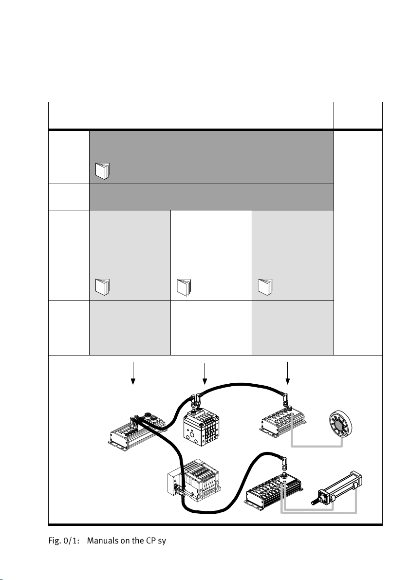
Information on further CP modules
ual for the relevant module. A summary is shown in fig. 0/1.
The CP field bus node FB11 has been certified by the ODVA.
can be found in the man
VI
Festo P.BE−CP−FB11−E−EN en 0802d
Page 9
Contents and general instructions
Important user instructions
Danger categories
This manual contains instructions on the possible dangers
which may occur if the product is not used correctly. These
instructions are marked (Warning, Caution,
shaded background and marked add itionally with a picto
gram. A distinction is made between the following danger
warnings:
Warning
This means that failure to observe this instruction may
result in serious personal injury or damage to property.
Caution
This means that failure to observe this instruction may
result in personal injury or damage to property.
etc.), printed on a
Festo P.BE−CP−FB11−E−EN en 0802d
Please note
This means that failure to observe this instruction may
result in damage to property.
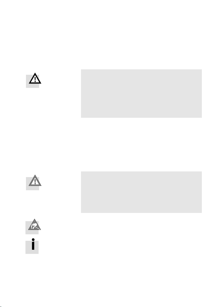
The following pictogram marks passages in the text which
describ
e activities with electrostatically sensitive compo
nents.
Electrostatically sensitive components may be damaged if
they are not handled correctly.
VII
Page 10
Contents and general instructions
Marking special information
The following pictograms mark passages in the text contain
ing special information.
Pictograms
Information:
Recommendations, tips and references to other sources of
information.
ccessories:
A
Information on necessary or sensible accessories for the
Festo product.
Environment:
Information on environment−friendly use of Festo products.
VIII
Text markings
S The
bullet indicates activities which may be carried out in
any order.
1.Figures denote activities which must be carried out in the
numerical order
specified.
Hyphens indicate general activities.
Festo P.BE−CP−FB11−E−EN en 0802d
Page 11
Contents and general instructions
Manuals on the CP system Peri−
pherals
Descrip
tion
Contents General basic information on the method of operation, fitting, installation
Descrip
tion
Contents Special information
CP system, installation and commissioning"
type P.B E−CPSYS−...
and commissioning of CP systems
CP field bus node,
programming and
diagnosis"
type P.B E−CP−FB...
or P.BE−VIFB...−10...
on commissioning,
programming and
diagnosing related
to the node used
CPV valve terminal,
pneumatics" or
CPA valve terminal,
pneumatics"
type P.B E−CPV−...
or P.BE−CPA−...
Information on fitting,
installing and commis
sioning CPA or CPV
valve terminals
CP modules,
electronics"
type P.B E−CPEA−...
Information on fitting,
installing and com−
missioning CP I/O
modules
Fig.0/1: Manuals on the CP system
Festo P.BE−CP−FB11−E−EN en 0802d
IX
Page 12
Contents and general instructions
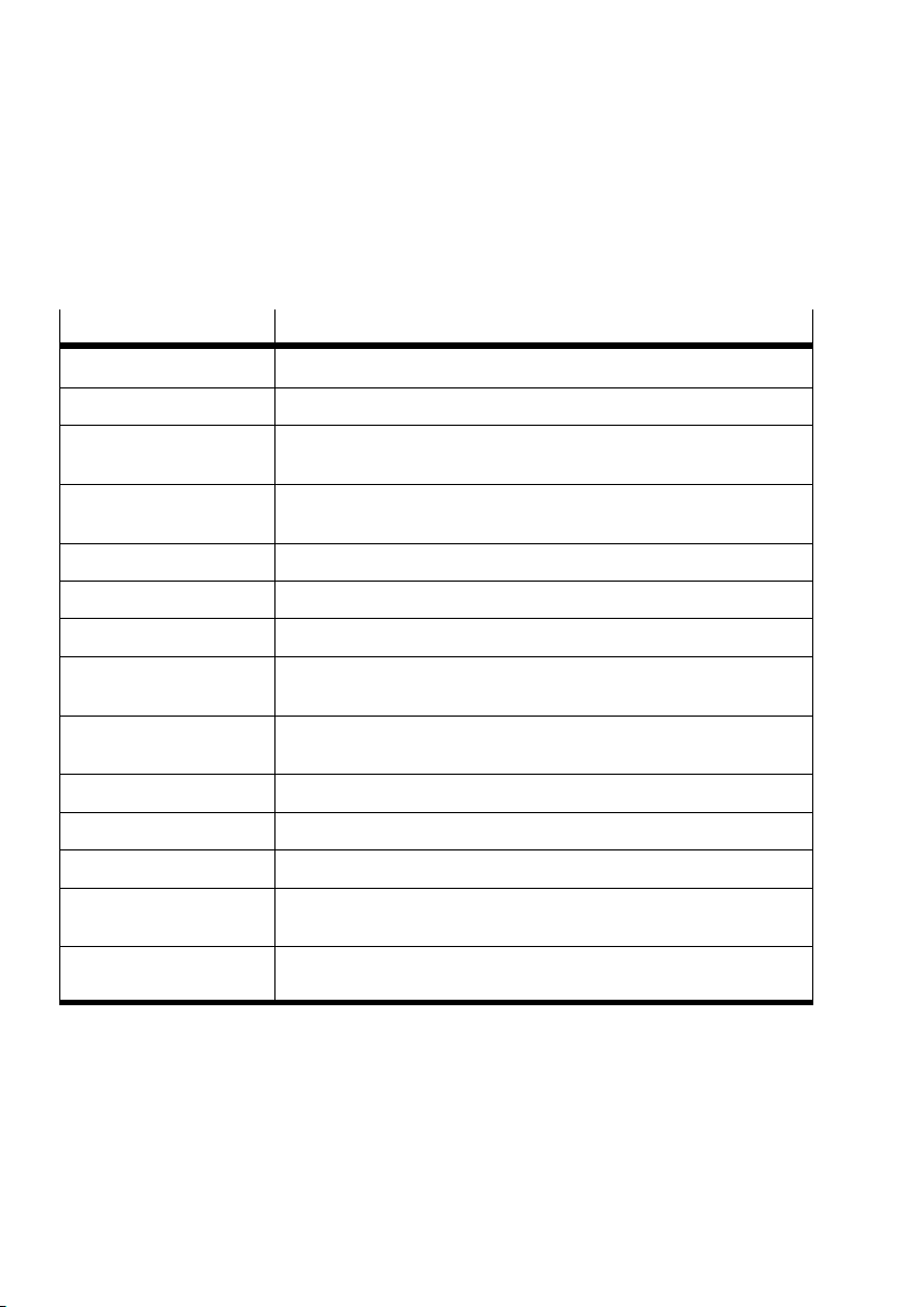
The following product−specific terms and abbreviations are
used in this manual:
Term/abbreviation
Busy bit Enable bit, for analysing data exchange with the CP system
CP cable Special cable for coupling the various CP modules
CP connection Plug or socket on the CP modules which enables the modules to be
CP modules Common term for various modules which can be incorporated in a
CP system Complete system consisting of CP field bus node and P modules
I Digital input
I/Os Digital inputs and outputs
I/O modules Common term for the CP modules which provide digital inputs and
Node CP field bus node with/without field bus connection to which the
Octet Number of address bytes assigned by the CP system
O Digital output
PLC/IPC Programmable logic controller/industrial PC
String Total number of I/O modules connected together on one CP connection
Meaning
connected with the CP cable
CP system
outputs (CP input modules and CP output modules)
I/O modules are connected
of the field bus node
String assignment Total number of all the I/O modules connected via strings to a
X
CP field bus node (0...3)
Festo P.BE−CP−FB11−E−EN en 0802d
Page 13

Installation
Chapter 1
1−1Festo P.BE−CP−FB11−E−EN en 0802d
Page 14

1. Installation
Contents
1. Installation 1−1 . . . . . . . . . . . . . . . . . . . . . . . . . . . . . . . . . . . . . . . . . . . . . . . . . . .
1.1 General instructions1−3 . . . . . . . . . . . . . . . . . . . . . . . . . . . . . . . . . . . . . .
1.2Configuring the CP system 1−4 . . . . . . . . . . . . . . . . . . . . . . . . . . . . . . . .
1.2.1 Setting the station number 1−5 . . . . . . . . . . . . . . . . . . . . . . . . . . . . .
1.2.2 Setting the field bus baud rate1−7 . . . . . . . . . . . . . . . . . . . . . . . . . . .
1.2.3 Setting compatibility (DeviceNet configuration) 1−8 . . . . . . . . . . . . . . . . . . . . . .
1.3Co
.4 Operating voltage1−10 . . . . . . . . . . . . . . . . . . . . . . . . . . . . . . . . . . . . . . . . . . . . . . .
1
1.5Connecting the CP node to the field bus1−12 . . . . . . . . . . . . . . . . . . . . . . . . . . . . .
nnecting CP modules 1−10 . . . . . . . . . . . . . . . . . . . . . . . . . . . . . . . . . . . . . . . . . .
. . . . . . .
. . . . . . . .
. . . . . . . . . .
. . . . . . . . .
1−2
Festo P.BE−CP−FB11−E−EN en 0802d
Page 15
1. Installation
1.1 General instructions
You can thereby avoid:
uncontrolled movements of loose tubing
Warning
Before carrying out installation and maintenance work,
switch off the following:
S the compressed air supply
S the operating voltage on the field bus node
(p
ins 1 and 2)
S the load voltage supply on the CP output modules.
unexpected movements of
the connected actuators
non−defined switching states of the electronic compo
nents.
Caution
The node of the CP system contains electrostatically sensi
tive components.
S Do not therefore touch any contacts.
S Observe the regulations
for handling electrostatically
sensitive components.
You will then prevent the electronics in the node from being
damaged.
Instructions on connecting the
power supply as well as gen
eral information on installing CP modules can be found in the
manual CP system".
Festo P.BE−CP−FB11−E−EN en 0802d
1−3
Page 16
1. Installation
1.2 Configuring the CP system
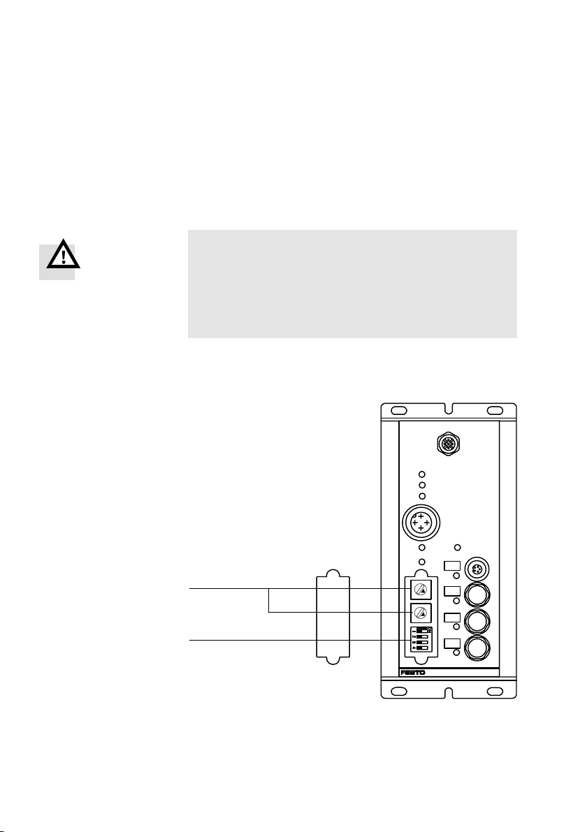
Switches for setting the configuration can be found under the
cover on the field bus node.
Warning
S Before commissioning: Make sure that DIL switch el
ements 3 and 4 are set to the desired setting for the
DeviceNet configuration (see chapter 1.2.3
S During operation: Do not modify the settings of the DIL
switches during operation.
You will thereby avoid undesired movements of the con
nec
ted actuators.
1 Address selector
switches for set
ting the station
number
2 DIL switch for set
ting the baud rate
and compatibility
with V1.4
1
2
6
5
6
5
78
9
134
2
78
9
134
2
).
BUSPOWER
BUSSTATUS
BUSERROR
24VDC
POWER
SAVE
0
0
ERROR
POWERV
0
1
2
3
1−4
Fig.1/1:Position of switch
Festo P.BE−CP−FB11−E−EN en 0802d
Page 17
1. Installation
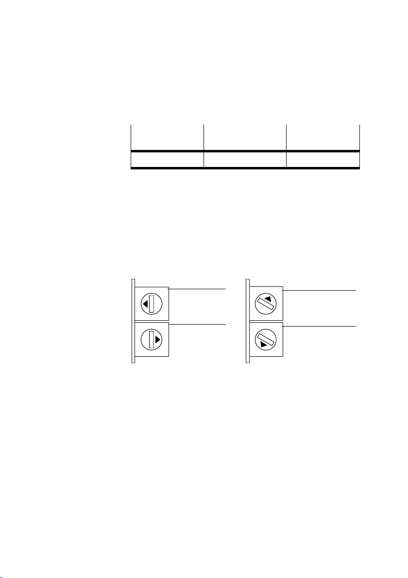
1.2.1 Setting the station number
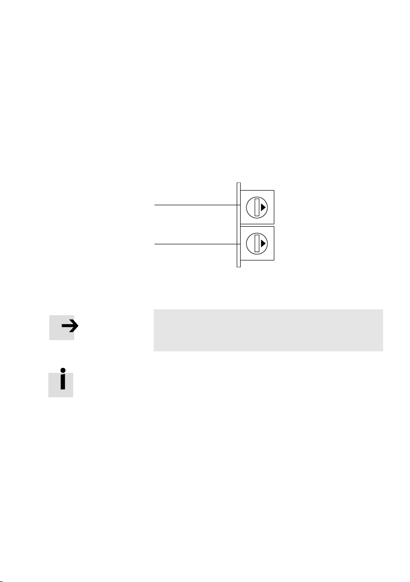
You can set the station number of the CP system with both
address selector switches. The switch positions are num
bered from 0 to 9. Th
indicates the units or tens figure of the station number set.
e arrow on the address selector switches
1 Address selector
switch for the
UNITS−figure
2 Address selector
switch for the
TENS−figure
7
8
6
9
5
0
1
1
2
4
3
2
7
8
6
9
5
0
1
4
3
2
Fig.1/2: Address selector switch
Please note
Station numbers may only be assigned once per module/
scanner.
Recommendation:
Assign the station numbers in ascending order. If necessary,
assign the field bus
addresses to suit the machine structure
of your system.
Festo P.BE−CP−FB11−E−EN en 0802d
1−5
Page 18
1. Installation
Possible station numbers
PLC Address
Station numbers
identification
DeviceNet Node/network module 0...63
Proceed as follows:
1.Switch off the operating voltage.
2.Assign an unused station number to the CP system.
3.Use a screwdriver to set the arrow of th
e relevant address
selector switch to the units or tens figure of the desired
station number (example see Fig. 1/3).
7
8
6
9
5
0
1
4
3
2
7
8
6
9
5
0
1
4
3
2
Setting for:
field bus address05
1
2
7
8
6
9
5
0
1
4
3
2
7
8
6
9
5
0
1
4
3
2
Setting for:
field bus address 38
1
2
1−6
1 UNITS
2 TENS
1 UNITS
2 TENS
Fig.1/3: Example of address settings
Festo P.BE−CP−FB11−E−EN en 0802d
Page 19
1. Installation
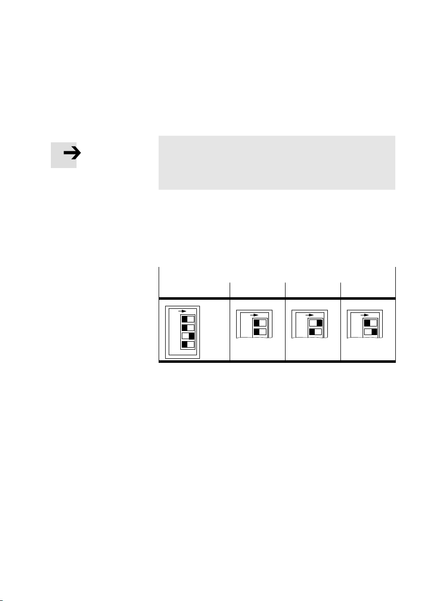
1.2.2 Setting the field bus baud rate
Please note
Set the field bus baud rate of the CP system so that it
corresponds to the setting of the field bus module/
interface of the master.
There is
a DIL switch with four switch elements under the
cover on the node.
Set the field bus baud rate on switch elements 1 and 2 as
follows:
Setting the field bus baud rate
DIL switch 125 kBaud 250 kBaud 500 kBaud
ON
1
2
3
4
ON
1
2
ON
1
2
1
2
Fig.1/4: Setting the field bus baud rate with switch
elements 1 and 2 of the DIL switch
ON
Festo P.BE−CP−FB11−E−EN en 0802d
1−7
Page 20
1. Installation
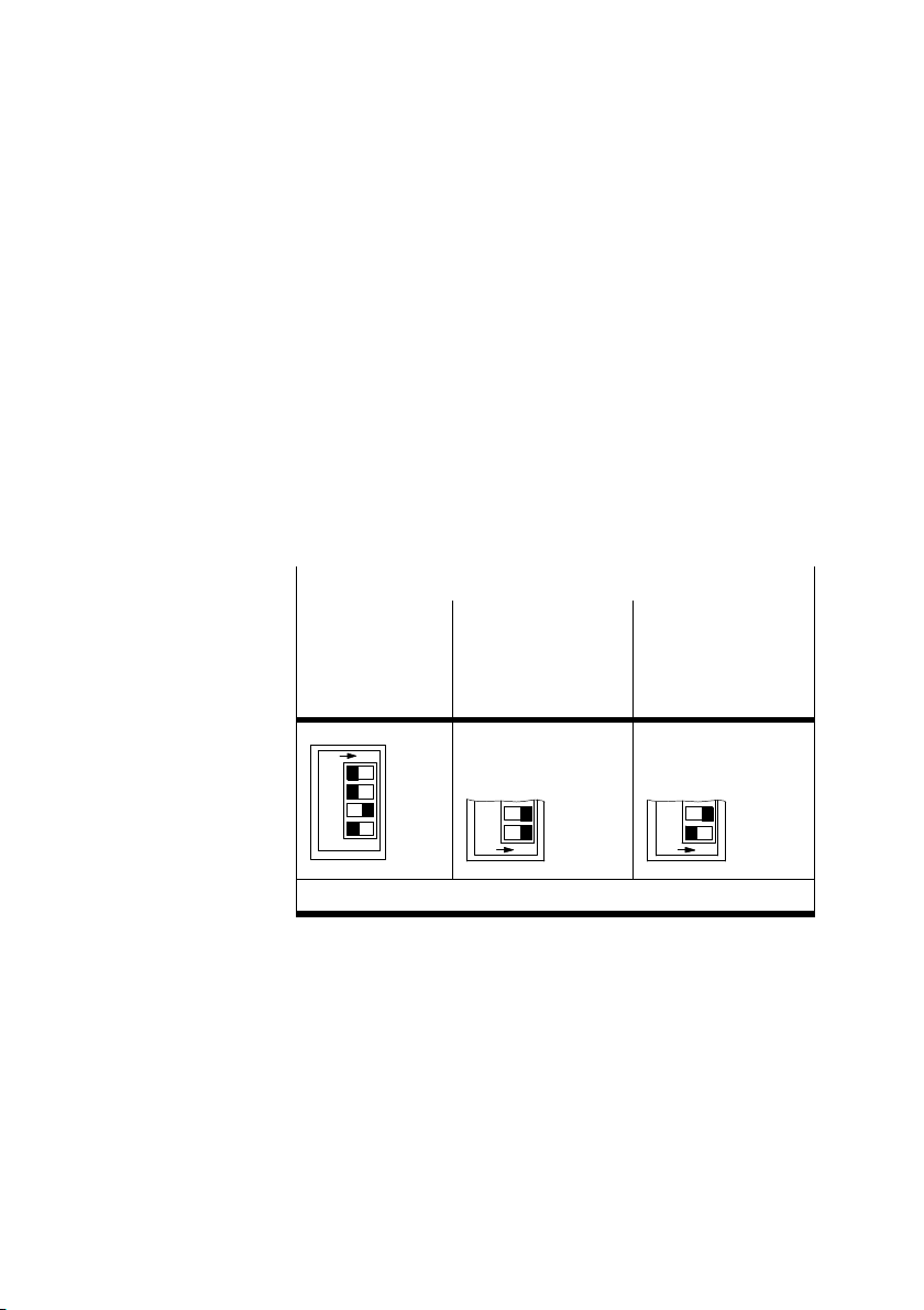
1.2.3 Setting compatibility (DeviceNet configuration)
Field bus node FB11 is available since February 2001 in an
updated and improved software version for the DeviceNet.
This current software version offers some simplificat
configuring and commissioning a CP system on the Device
Net.
The current software version is no longer compatible with
field bus nodes with the
can, however, switch the field bus node to the earlier software
version and thereby restore compatibility with th
DeviceNet configuration.
Setting compatibility
DIL switch Compatible to earlier
earlier software version (V1.4). You
versions
Version 1.4
(until 01.02.2001)
ions in
e earlier
Current software
version
Version 2.1
(as from 01.02.2001)
(as supplied)
1−8
ON
1
2
3
4
3
4
ON
3
4
ON
Switch element 3 must always be set to ON.
Fig.1/5:Setting compatibility (DeviceNet configuration)
with switch element 4 of the DIL switch
Festo P.BE−CP−FB11−E−EN en 0802d
Page 21

1. Installation
Please note
If you wish to replace a field bus node with an earlier soft
ware version by a node with the current software version
V2.1 (01.02.01)
and maintain your current DeviceNet con
figuration:
S Set switch element 4 of the DIL switch to ON. The field
bus node then supports the earlier
software version
V1.4 and you will avoid configuration errors on the
existing DeviceNet.
When compatibility with software version 1.4 is set, the
node rea
cts like Device type 25".
Diagnostic bytes are not then available.
If you wish to use a node with the current software version
(as supplied):
Festo P.BE−CP−FB11−E−EN en 0802d
S configure
with chapter 2.2.
the CP system in your DeviceNet in accordance
1−9
Page 22
1. Installation
1.3 Connecting CP modules
Warning
S For connecting the CP modules to a string, use the
special CP cable from Festo (type KVI−CP−1−...).
S Please note that the total length of cable o
must not exceed 10 m.
You can thereby avoid:
faults in data exchange between the node and the
connected CP modules
n a string
1.4 Operating voltage
Information on th
CP system, installation and commissioning".
Warning
S Use only PELV circuits as per IEC/DIN EN 60204−1 (Pro
tective Extra−Low Voltage, PELV) for the electrical supply.
Consider also the general requirements
in accordance with IEC/DIN EN 60204−1.
S Use power supplies which guarantee reliable electrical
isolation of the operating voltage as per IEC/DIN
60204−1.
By the use of PELV circuits, protection against electric shock
(protection against direct and indirect contact) is guaranteed
in accordance with IE
machines, General requirements).
e procedure can be found in the manual
for PELV circuits
EN
C/EN 60204−1 (Electrical equipment for
1−10
Festo P.BE−CP−FB11−E−EN en 0802d
Page 23

1. Installation
Please note
Check within the framework of your EMERGENCY STOP
circuit, to ascertain the measures necessary for putting
your machine/system into a safe stat
e in the event of an
EMERGENCY STOP (e.g. switching off the operating voltage
for the valves and output modules, switching off the com
pressed air).
Information
on the procedure as well as on connecting cables
and current requirements can be found in the manual
CP system, installation and commissioning".
Festo P.BE−CP−FB11−E−EN en 0802d
1−11
Page 24
1. Installation
1.5 Connecting the CP node to the field bus
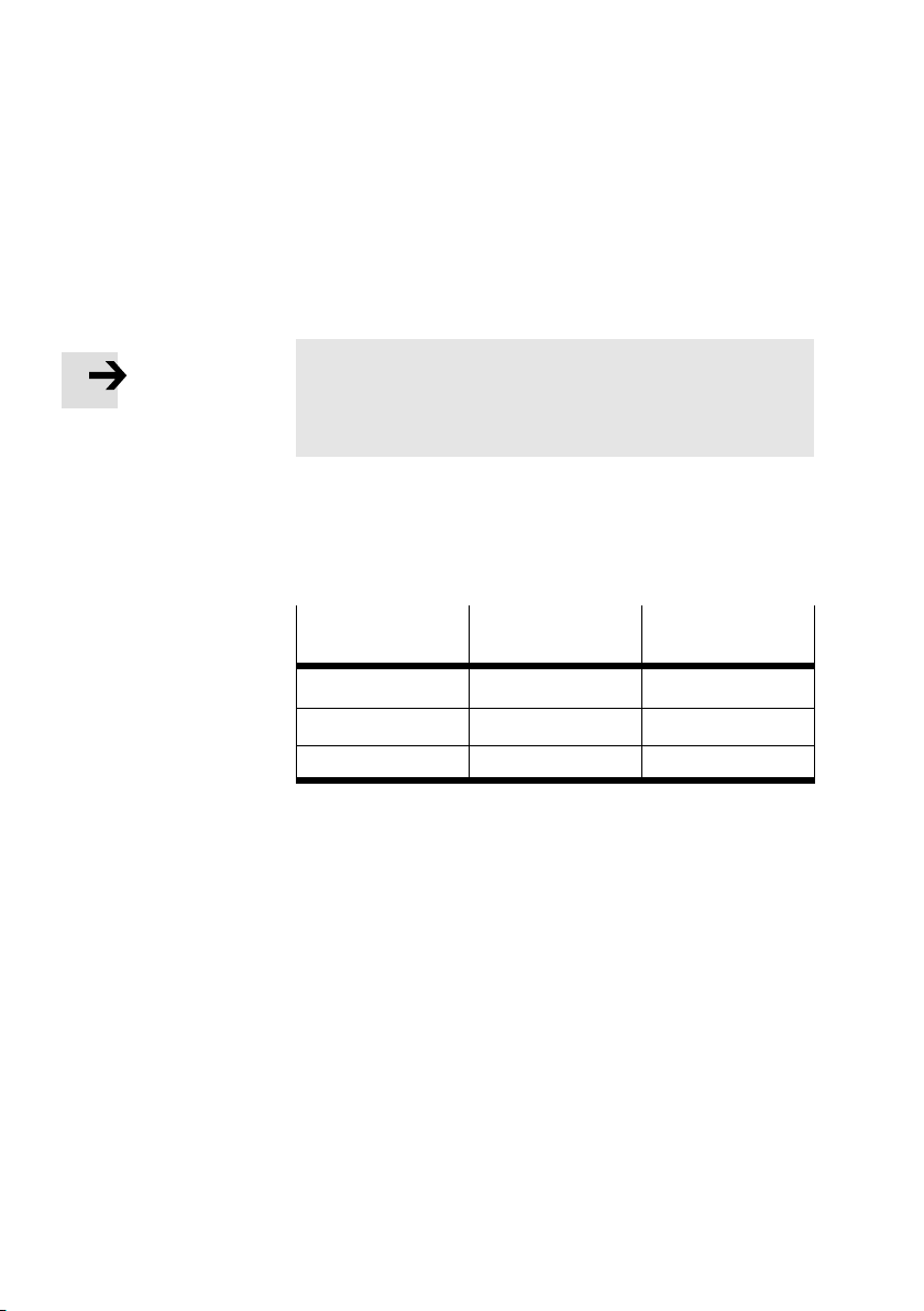
Cable selectionUse a twisted, screened 4−wire cable for the field bus.
Please note
Refer to the PLC manual for your controller for the type of
cable to be used. Take into account the distance and the
field bus baud rate selected.
The following
table contains reference values for the maxi
mum distances depending on the baud rate selected. De
tailed information can be found in the manuals for your con
trol system.
Baud rate
Maximum
distance
500 kBaud 50...100 m 0.75...3 m
250 kBaud 200 m 3 m
125 kBaud 500 m 3 m
Maximum branch
line length
Not all the baud rates mentioned are supported by all con
trollers, PLC/IPC. Note also any limitations in the maximum
branch line length.
1−12
Festo P.BE−CP−FB11−E−EN en 0802d
Page 25
1. Installation
Field bus plug There is a field bus plug on the node for connecting the node
to the field bus. The two bus cables, the power supply (+24V
and
0 V) for the bus interface as well as the cable screening
are connected to this plug.
The hardware basis of the bus interface is the CAN−bus. It is
typical for this bus that the bus interface is supplied with
power via the field bus plug.
Connection to the bus is made with a 5−pin M12 socket
with
PG9 screw connector. You can order these from Festo (type
FBSD−GD−9−5POL, part no. 18324). Alternatively, you can use
the bus cables of other manu
facturers (see Appendix A).
Please note
Use only T−adapters and branch line lengths which are
permitted for your control system.
Information on this can be found in the manual for your
PLC.
Appendix A gives a summary of matching installation
accessories.
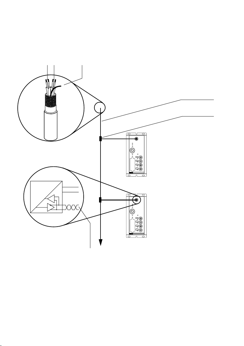
The following summary shows the bus connection.
Festo P.BE−CP−FB11−E−EN en 0802d
1−13
Page 26
1. Installation
1
23
BUSPOWER
MODULE STATUS
I/OERROR
24VDC
POWER
SAVE
0
1
2
3
ERROR
4
5
POWER V
6
1 Operating voltage
for the bus interface
2 Field bus cables
3 Screening/shield
Fig.1/6: Structure of bus cables
1−14
BUSPOWER
MODULE STATUS
I/OERROR
24VDC
POWER
POWER V
SAVE
0
1
2
3
ERROR
4 Branch line
5 T−adapter
6 Bus cables
Festo P.BE−CP−FB11−E−EN en 0802d
Page 27
1. Installation
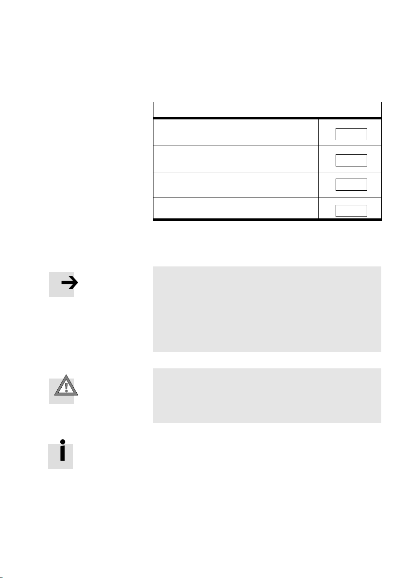
Current consumption of all bus interfaces
Number of connected
CP field bus nodes _______ * 50 mA
Current consumption of the remaining field bus
interfaces
Current consumption of sensor inputs/sensor
supply which is supplied via the bus
Total current consumption of the bus interface
Σ A
+
Σ A
+
Σ A
Σ A
=
Avoid long distances between the bus power supply and the
bus slaves.
Please note
Bus slaves of different manufacturers show different toler
ances in respect of interface power supply. Ta k e this into
consideration when planni
ng the bus length.
The following applies to valve terminal type 10:
V
= 25 V
max
V
= 11.5 V
min
Caution
S Make sure of the correct polarity when you connect the
field bus interface.
S Connect the screening/shield.
Festo P.BE−CP−FB11−E−EN en 0802d
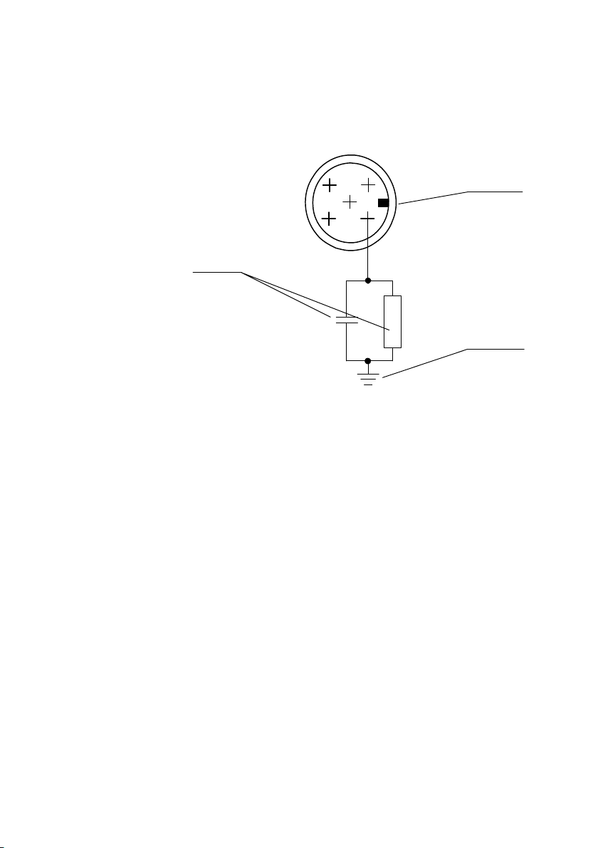
The following diagram shows the pin assignm
ent of the field
bus interface. Connect the field bus cables to the appropriate
pins of the bus cable socket. Note also the connecting in
structions
in further diagrams, as well the instructions in the
PLC manual for your controller.
1−15
Page 28
1. Installation
3
1 Pin assignment
1:Screening/shield
2:+ 24 V Bus
3:GND Bus
4: Data +
5: Data −
2
3
5
14
1
2
1−16
2 Node housing, functional earth
3 Internal RC network
Fig.1/7:Pin assignment of the field bus interface
Festo P.BE−CP−FB11−E−EN en 0802d
Page 29
1. Installation
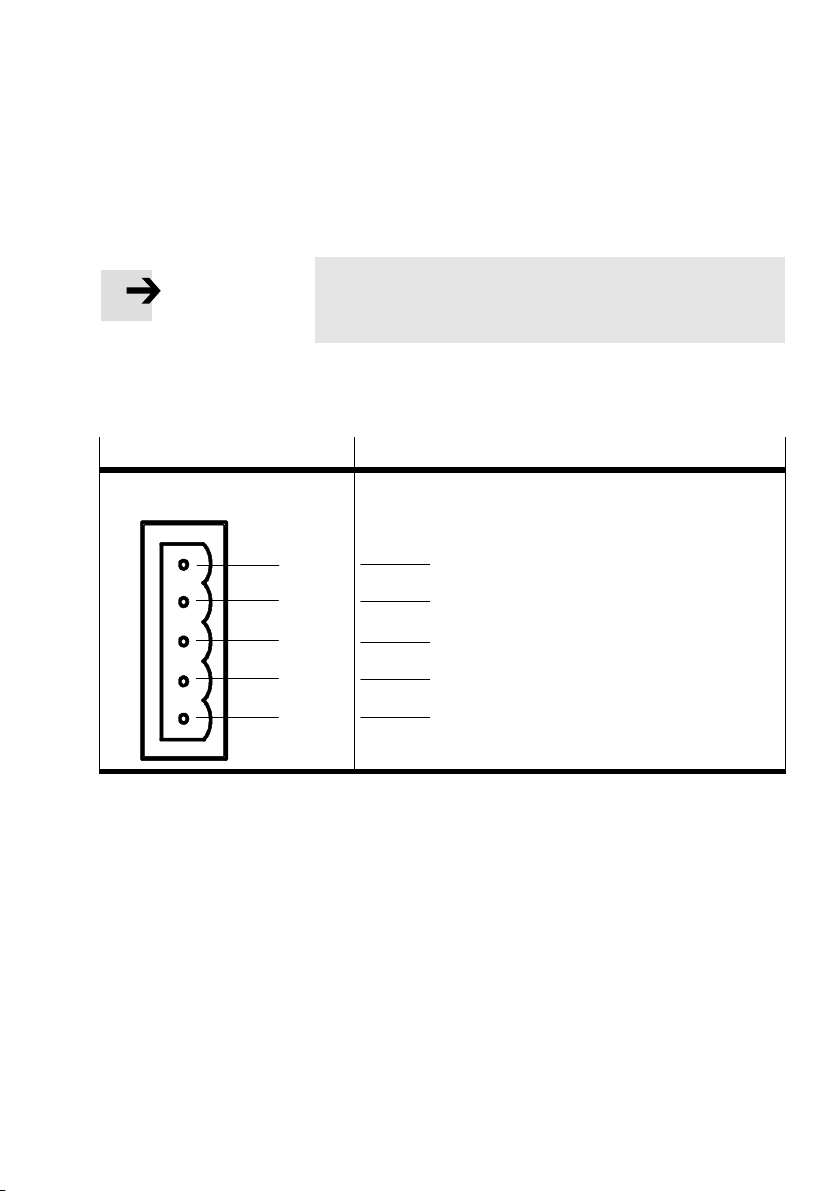
Connection instructions for DeviceNet
Please note
Always check the pin assignment of the module in the PLC
manual for your controller.
Connect the field bus cable of your control system to the field
bus interface of the node as follows:
PLC pin/plug assignment
ViewSignal designations
RED
WHITE
BARE
BLUE
BLACK
Pin assignment of the field bus interface on the node
+ 24 V Bus
Data +
Screening/shield
Data −
GND Bus
Fig.1/8: Connection instructions for the DeviceNet
Pin
2
4
1
5
3
Festo P.BE−CP−FB11−E−EN en 0802d
1−17
Page 30
1. Installation
Terminating resistor
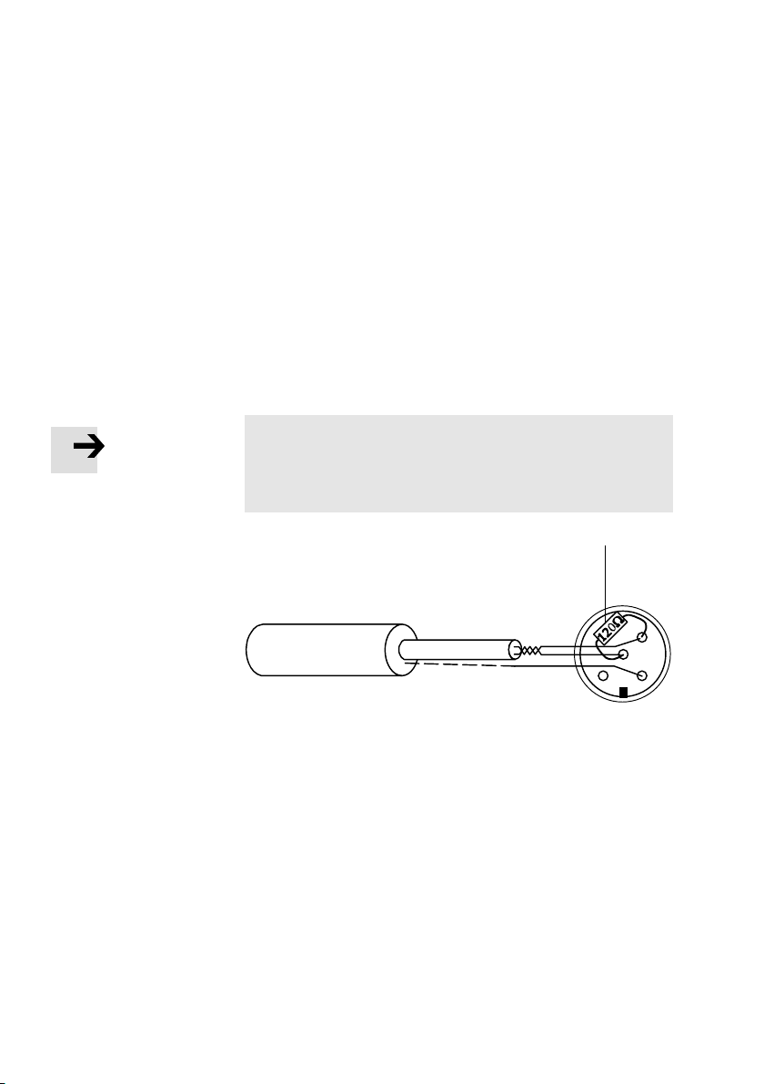
If the CP system to be connected is at the end of the field bus,
a terminating resistor (1220 Ohm, 0.25 W) must be fitted in
the socket of
the field bus cable (adaption reqired).
Fitting a terminating resistor
1. Crimp the wires of the resistor together with those of the
field bus cable b
etween the cores Data+ (pin 4) and
Data− (pin 5) of the bus cable socket.
Please note
In order to ensure reliable contact, we recommend that
you clamp the wires of the resistor and those of the field
bus cable in a common cable end
sleeve.
1
1−18
4
5
12
1 Terminating resistor
Fig.1/9: Terminating resistor in the socket of the field bus
cable
2.Fit the bus cable socket onto the field bus plug.
Festo P.BE−CP−FB11−E−EN en 0802d
Page 31

Commissioning
Chapter 2
2−1Festo P.BE−CP−FB11−E−EN en 0802d
Page 32

2. Commissioning
Contents
2. Commissioning 2−1 . . . . . . . . . . . . . . . . . . . . . . . . . . . . . . . . . . . . . . . . . . . . . . . .
2.1
2.1.1 Saving the string assi
2.1.2Compiling the configuration lis
2.1.3 Switching on the operating v
2.2Commissioning and addressing on the DeviceNet 2−
2.2.1 General information 2−7 . . . . . . . . . . . . . . . . . .
2.2.2Configuring DeviceNet slaves (EDS) 2−8 . . . . . . . . .
2.2.3 Valid instructions for parametrizing on the DeviceNet 2−10 . . . .
2.2.4 Instructions on parametrizing with RSNetWorx for DeviceNet 2−11 . . . . . . . . . . .
Preparing the CP system for commissioning 2−3 . . . . . . . . . . . . . . . . . . . . . . . . .
gnment 2−3 . . . . . . . . . . . . . . . . . . . . . . . . . . . . . . . . . . . . .
t 2−4 . . . . . . . . . . . . . . . . . . . . . . . . . . . . . . . . . . .
oltage2−6 . . . . . . . . . . . . . . . . . . . . . . . . . . . . . . . . .
. . . . . . . . . . . . . . . . . . . . . . . . . . .
. . . . . . . . . . . . . . . . . . . . . . .
. . . . . . . . . . . . . .
7 . . . . . . . . . . . . . . . . . . . . .
2−2
Festo P.BE−CP−FB11−E−EN en 0802d
Page 33
2. Commissioning
2.1 Preparing the CP system for commissioning
Please note
Supply the CP field bus node separately with operating
voltage (see the manual CP system"). The field bus inter
face of the CP node is supplied
cable.
2.1.1 Saving the string assignment
Please note
Before commissioning the CP system
Prepare the CP system for commissioning on the field bus
(see also manual CP system, installation and commis−
sio
ning").
with power via the field bus
Festo P.BE−CP−FB11−E−EN en 0802d
Before commissioning the CP system on the field bus,
proceed as follows:
1. Connect the operating voltage for the node (see
manual CP system").
2
. Connect the CP modules (see manual CP system").
3.Switch on the operating voltage.
4. Save the striing assignment by pressing the SAVE button.
5.Switch off the
operating voltage for the node.
2−3
Page 34

2. Commissioning
2.1.2Compiling the configuration list
Configuration list Before commissioning or programming, compile a configur
ation list of all connected field bus slaves. On the basis of this
list, you can:
Ascertaining the
configuration
carry out a compar
ACTUAL configurations in order to ascertain if there are
any connection faults
accesss these specifications during the syntax check of
program, in order to avoid addressing errors.
Configuration of the CP system requires a very accurate pro
cedure, as different configuration specifications
times required for each system, due to the modular structure.
Please observe here the instructions in the following section
The configuration data must be known or ascertained for
each bus slave. Ascertain here the address range occupied
by the CP s
ystem.
ison between the NOMINAL and the
a
are some
Address assignment of the CP system
The size of the address range occupied by the CP system de
pends on the number of the last used string (see also manual
CP system"). The last
lower strings each occupy 16 input addresses and 16 output
addresses.
If no string is occupied, the node will respond t
as standard with 2 occupied inputs and outputs (e.g. for test
purposes).
used string as well as all numerically
o the field bus
s.
2−4
Festo P.BE−CP−FB11−E−EN en 0802d
Page 35
2. Commissioning
The number of occupied input addresses is therefore always
identical to the number of occupied output addresses, irre
spective of the equipment fitted on the
CP system. Unused
addresses in the occupied address range remain reserved for
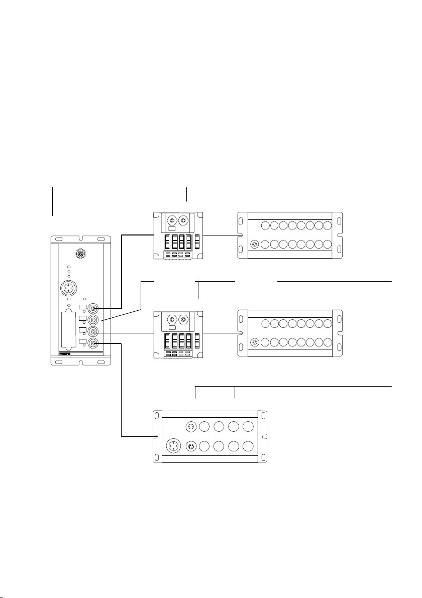
later extensions of the CP system. The diagram below shows
an example:
1
O0...O63
I0...I63
BUSPOWER
MODULESTATUS
I/OERROR
POWER
SAVE
ERROR
O= Output
I= Input
2
O0...O7 (O8...O15)
24VDC
POWERV
0
1
2
3
(O16...O31)(I16...I31)
O32...O39 (O40...O47)I32...I47
I0...I15
2
2
O48...O55 (O56...O63) (I48...I63)
1 Address range occupied by the CP system (last used string is string 3)
2 ( ) = reserved address range (occupied or unused)
Fig.2/1: Address assignment of a CP system, example
Festo P.BE−CP−FB11−E−EN en 0802d
2−5
Page 36

2. Commissioning
2.1.3 Switching on the operating voltage
Please note
Please observe also the switching−on instructions in the
PLC manual for your controller.
When you switch on your controller, it automatically
out a comparison between the NOMINAL and the ACTUAL
configurations. For this configuration run it is important that:
the configuration specifications are complete and correct.
the power supply for the programmable logic controller
and that for the field bus slaves are switched on either
simultaneously or in the sequence indicated above.
Please observe the following points when switching on the
power supply:
Common supplyIf there is a common supply for the control sy
field bus slaves, the power should be switched on via a cen
tral power unit or central switch.
Separate supplyIf the
re is a separate supply for the control system and for the
field bus slaves, the power should be switched on in the fol
lowing sequence:
1.the power supply for all the field bus slaves
2.the power supply for the control system.
carries
stem and for the
2−6
Festo P.BE−CP−FB11−E−EN en 0802d
Page 37
2. Commissioning
2.2 Commissioning and addressing on the DeviceNet
Please note
Field bus node type CP FB11−E can be used on all
DeviceNet masters.
This chapter describes configuration and commissioning
using as an example the
controllers from Allen−Bradley.
2.2.1 General information
Please note the following special features when using the
node on the DeviceNet:
The addresses of all recognized DeviceNet slaves can be
freely assigned
the Scan list.
as M−file addresses or as discrete I/Os in
Festo P.BE−CP−FB11−E−EN en 0802d
The addresses of network slaves are assigned in ascend
ing order.
The input and output addresses can be assigned
dently of each other.
Please note
Order the addresses of the network slaves so that there is
sufficient reserve for later extensions.
The following sections contain generally valid instruct
the configuration of the node on the DeviceNet.
Detailed information can be found in the documentation or in
the help for the configuration program
you are using.
indepen
ions on
2−7
Page 38

2. Commissioning
2.2.2Configuring DeviceNet slaves (EDS)
When you commission a new DeviceNet slave the first time,
you must inform your configuration program of certain fea
tures of the slave. The features of
usually administered by the configuration program in a list or
library e.g. EDS library" (EDS for electronic data sheets).
the various slaves are
The following possi
bilities are available for extending an
EDS library":
Installing an EDS library
Entering the slave features by hand
Installing an EDS library
Current GSD files can be found on the Festo
Internet pages
under:
www.festo.com/fieldbus
You can obtain the GSD files and further configuration aids
with the CD ROM Utilities" from Festo:
type P. CD−VI−UTILITIES−2, part no
. 533500
The most up−to−date GSD files are always available via the
Internet.
EDS file The EDS file contains all the necessary features of node type
CP FB11−E. You can
install this file with the aid of your con
figuration program.
ICO/BMP file Depending on the configuration program used, you can as
sign the Bitmap file or Icon file
to the node. The node will then
be appropriately represented in the configuration program.
2−8
Festo P.BE−CP−FB11−E−EN en 0802d
Page 39
2. Commissioning
Instructions on installing an EDS file and an ICO or BMP file
can be found in the manual or in the help for your configur
ation program.
Entering the slave features by
hand
When an EDS file is installed, the following information about
the DeviceNet slave is added to the EDS library. This informa
tion can also be entered manua
Information
Vendor name Festo Corporation (26)
Device type Communication adapter (12)
Product code 192
Major revision / minor revision 2.1
Input size / output size 8 bytes / 8 bytes
Product name CP−FB11−E
Catalogue number 18227
lly.
Manual
When the EDS library has been extended, the node is entered
in the slave list as a possible DeviceNet slave. It can now be
added to a ne
twork.
Festo P.BE−CP−FB11−E−EN en 0802d
2−9
Page 40

2. Commissioning
2.2.3 Valid instructions for parametrizing on the DeviceNet
When the slave features have been configured (e.g. by instal
ling the EDS file), the following steps are required for parame
trizing, depending on
1.Insert the slave in the project/network (online or offline).
If the slave is inserted e.g. offline, it will be selected from
the slave list and added to the network.
2.Assigning a slave to a scanner. A network can contain
several scanners. The slave must be assigned to
scanner.
3. Determine the I/O parameters of the slave. The following
specifications are required here:
the configuration program.
a
S the number of I/O bytes to be transmitted. The
follow
ing applies to node CP FB11−E:
− 2, 4, 6 or 8 input bytes occupied
− 2, 4, 6 or 8 output bytes occupied
The number of occupied I/O bytes depends on the
highest occupied string number (2 inputs and 2 out
puts on each occupied string).
S Specification of communication type. The following
applies to node CP FB11−E:
−Polled
communication
or
− Change of state / cyclic
In addition to these communication connnections a
Strobed I/O connection must be used in each case for
the diagnosis
.
2−10
Festo P.BE−CP−FB11−E−EN en 0802d
Page 41
2. Commissioning
Please note
The following applies to an SLC 500 with an Allen−Bradley
scanner type 1747−SDN:
Change of state / Cyclic can only be used in combination
with the di
agnosis via Strobed I/O as from software ver
sion V4.015 of the scanner.
Polled I/O with Strobed I/O is also supported by earlier
versions.
S Assign the I/O addresses
of the slave to the PLC
operands.
S Assign 4 diagnostic bytes to the PLC operands.
4. Load the configuration into the scanner.
2.2.4 Instructions on parametrizing with RSNetWorx for DeviceNet
This section gives instructions on parametrizing with
RSNetWorx for DeviceNet version 2.11.51 from Rockwell.
Please note
All the steps explained refer as an axample to the Allen−
Bradley scanner 1747−SDN. They also apply to other
masters.
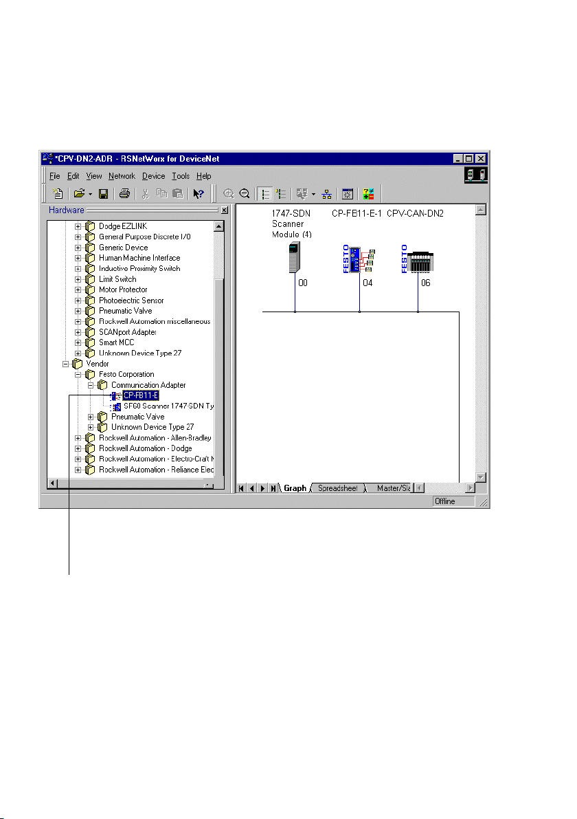
Inserting the slave into the project/network
RSNetW
will support you in installing the EDS file. When the EDS file
has been installed, the node is i
ware". By pulling the cursor across, you can insert slaves in
the network on the right−hand side.
orx for DeviceNet contains an EDS assistant which
ncluded in the list Hard
Festo P.BE−CP−FB11−E−EN en 0802d
2−11
Page 42
2. Commissioning
1
1 Node type CP FB11−E in the list Hardware"
Fig.2/2: Hardware list and network in RSNetWorx for DeviceNet
2−12
Festo P.BE−CP−FB11−E−EN en 0802d
Page 43
2. Commissioning
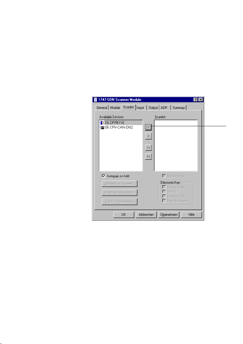
Assigning a slave to a scanner
A double click on the desired scanner in the network opens a
dialogue field in which you can assign the available slaves to
the
scanner.
1
Festo P.BE−CP−FB11−E−EN en 0802d
Button for assigning the slave
1
Fig.2/3:Register card Scanlist" (example)
2−13
Page 44
2. Commissioning
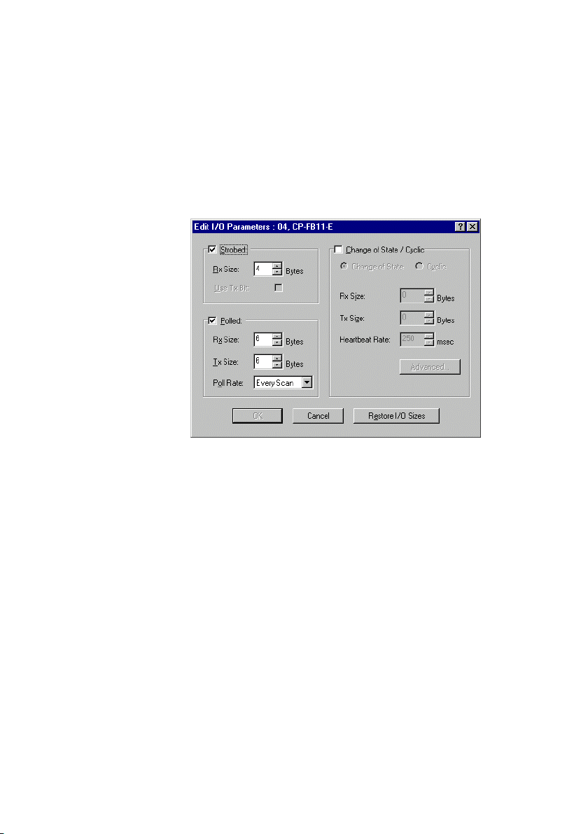
Parametrizing slaves
A double click on the slave opens a dialogue field in which
you can determine the I/O parameters of the slave.
2−14
Fig.2/4: Dialogue field Edit I/O parameters"
The following applies to node CP FB11−E:
The number of I/O bytes to be transmitted is fixed at 2
input bytes and 2 o
utput bytes per CP string.
Festo P.BE−CP−FB11−E−EN en 0802d
Page 45
2. Commissioning
Assigning the I/O addresses of the slave
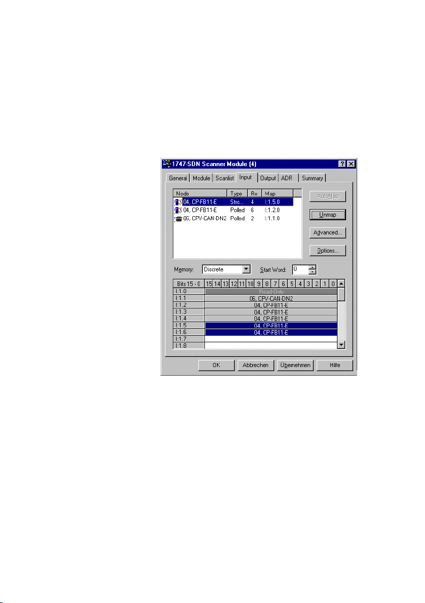
With the register cards Output" and Input" you can assign
the I/O addresses of the node to the PLC operands.
Festo P.BE−CP−FB11−E−EN en 0802d
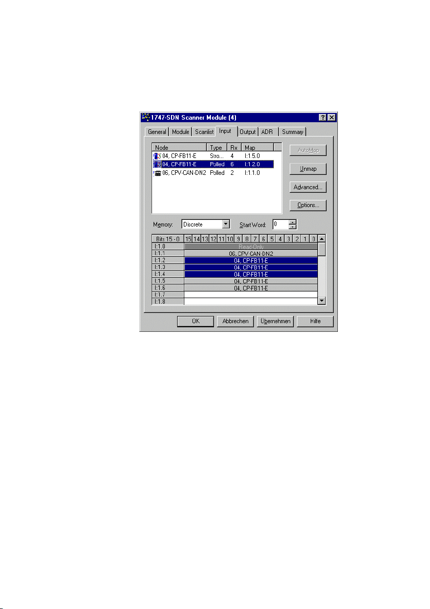
Fig.2/5: Address assignment of the input of the 4−byte
diagnostic information (Strobed)
2−15
Page 46
2. Commissioning
2−16
Fig.2/6: Address assignment of the input of the physical
sensor signals (Polled)
Festo P.BE−CP−FB11−E−EN en 0802d
Page 47
2. Commissioning
Festo P.BE−CP−FB11−E−EN en 0802d
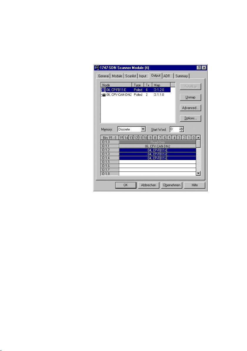
Fig.2/7: Address assignment of the output (example)
Load the configuration into the scanner
To conclude, load the configuration into the scanner. Further
information on this can be found in
the documentation for
your scanner.
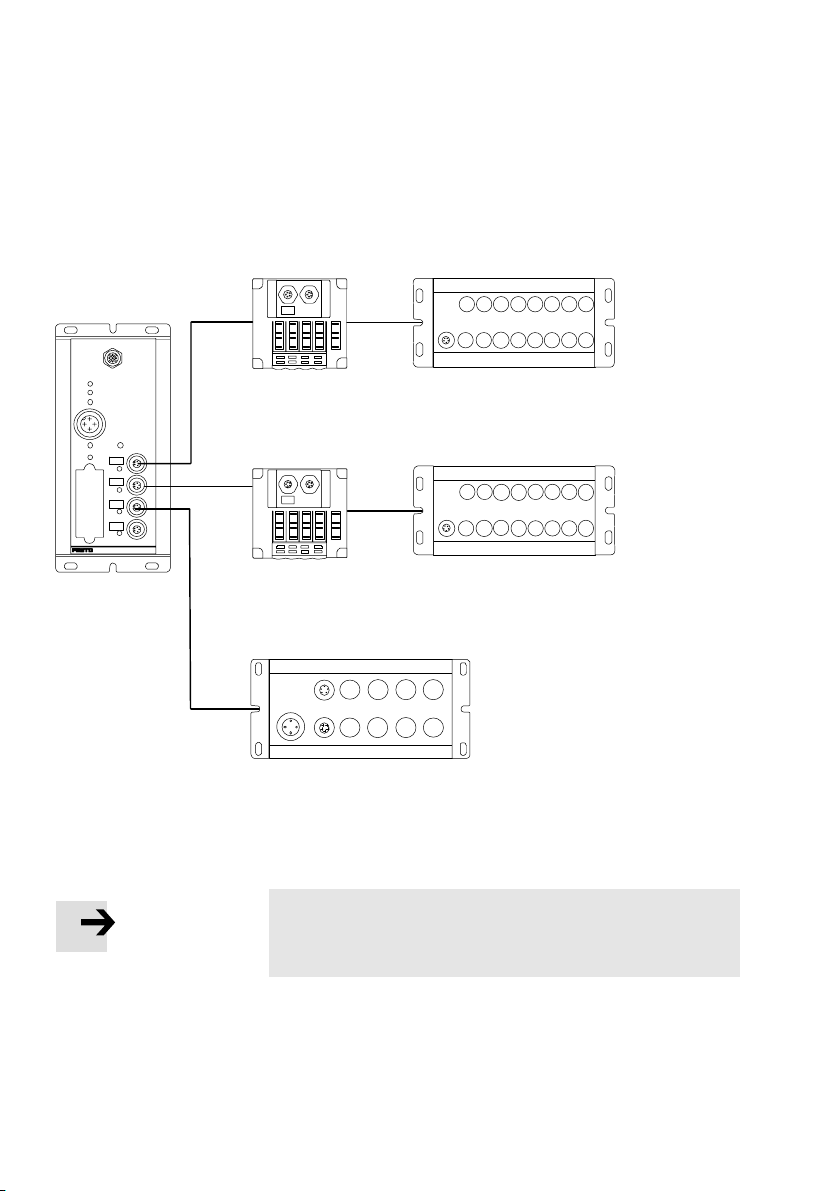
Example: Scanner 1747−SDN (SLC 500 series)
Valve terminal #12 with:
4 occupied strings: strings number 0, 1, 2 and 3
8 input bytes, input address as from I:004//00
8 output bytes, output address as f
rom O:004/00
2−17
Page 48
2. Commissioning
O:1.2/00...O:1.2/07
(O:1.2/08...O:1.2/15)
I:1.2/00...I:1.4/15
O:1.2/00...O:1.4/15
BUSPOWER
MODULESTATUS
I/OERROR
24VDC
POWER
POWERV
0
SAVE
1
2
3
ERROR
O:1.3/00...O:1.3/07
(O:1.3/08...O:1.3/15)
O:1.4/00...O:1.4/07
(O:1.4/08...O:1.4/15)
Diagnostic words
for Strobed I/O:
I:1.5/00...I:1.6/15
Address range occupied by the CP system
( ) = reserved address range (occupied but unused)
I:1.2/00...I:1.2/15
I:1.3/00...I:1.3/15
(I:1.4/00...I:1.4/15)
Fig.2/8: Addressing example for scanner 1747−SDN (last used string is 3)
Please note
For access via the communication type explicit messag
ing" the objects are described in Appendix A.2.
2−18
Festo P.BE−CP−FB11−E−EN en 0802d
Page 49

Diagnosis
Chapter 3
3−1Festo P.BE−CP−FB11−E−EN en 0802d
Page 50

3. Diagnosis
Contents
3. Diagnosis 3−1 . . . . . . . . . . . . . . . . . . . . . . . . . . . . . . . . . . . . . . . . . . . . . . . . . . . . .
3.1 LED displays on the bus node3−3 . . . . . . . . . . . . . . . . . . . . . . . . . . . . . . . . .
3.1.1 Normal operating status3−5 . . . . . . . . . . . . . . . . . . . . . . . . . . . . . . . . . . .
3.1.2Diagnostic operating voltage POWER or POWER V 3−6 . . . . . . . . . . . . . . . . . . . .
3.1.3Diagnostic bus LE
3.2 Testi
3.3 Reaction to errors in the control system 3−11 . . . . . . . . . . . . . . . . . . . . . . . . . . . . .
3.4 Diagnosis on the DeviceNet 3−12 . . . . . . . . . . . . . . . . . . . . . . . . . . . . . . . . . . . . . . .
3.4.1Diagnosis via the Software Configurator 3−12 . . . . . . . . . . . . . . . . . . . . . . . . . . . .
3.4.2Diagnosis via user program
3.5 Short circuit/overlo
3.6 Short circuit in the sensor supply at an
ng the valves 3−9 . . . . . . . . . . . . . . . . . . . . . . . . . . . . . . . . . . . . . . . . . . . . . . .
Ds 3−7 . . . . . . . . . . . . . . . . . . . . . . . . . . . . . . . . . . . . . . . . . . . . .
ad at an output module 3−15 . . . . . . . . . . . . . . . . . . . . . . . . . .
input module 3−16 . . . . . . . . . . . . . . . . . .
. . . .
. . . . . .
3−14 . . . . . . . . . . . . . . . . . . . . . . . . . . . . . . . . . . . . . . .
3−2
Festo P.BE−CP−FB11−E−EN en 0802d
Page 51
3. Diagnosis
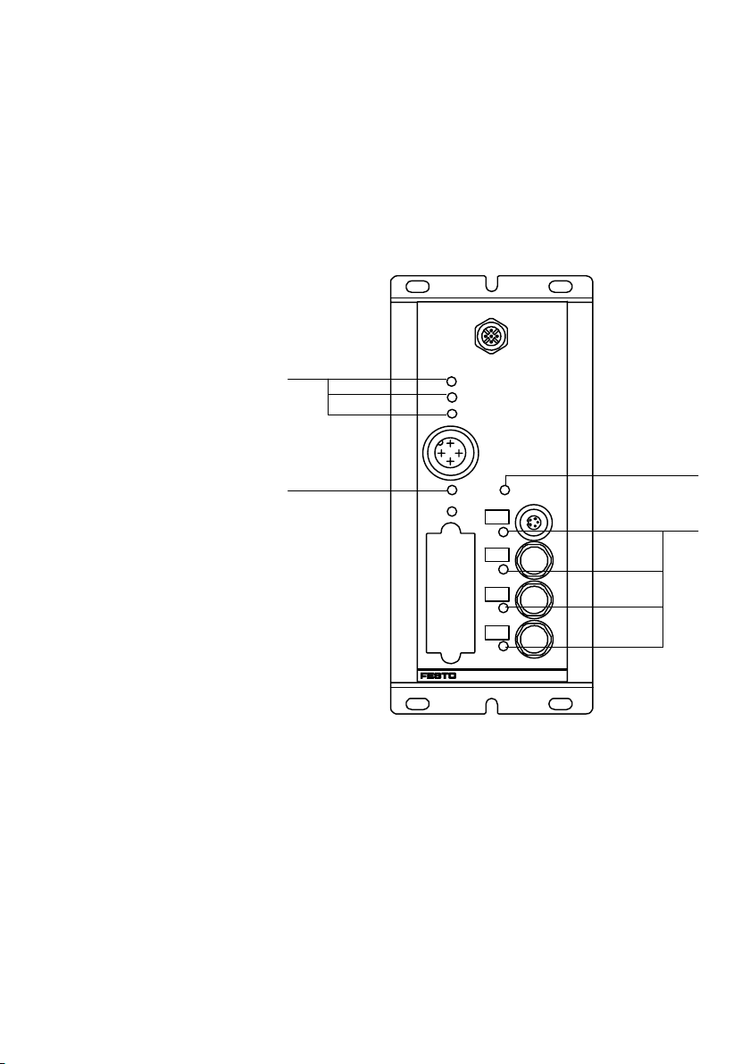
3.1 LED displays on the bus node
The LEDs on the node permit fast on−the−spot diagnosis.
1 Bus LEDs
2 Operating
voltage LEDs
3 String LEDs
1
BUSPOWER
BUSSTATUS
BUSERROR
24VDC
2
POWER
SAVE
0
1
2
3
ERROR
Fig.3/1:LEDs of the CP node FB11
2
POWERV
3
Festo P.BE−CP−FB11−E−EN en 0802d
3−3
Page 52

3. Diagnosis
LEDs LED designation Meaning
BUS POWER Operating voltage display for the
BUS STATUS Module status display lights up when the operating status is
BUS ERROR Transmission error display lights up when data transfer on the bus
POWER Operating voltage display of
POWER V Operating voltage display of the
0...3
ERROR
bus interface
internal electronics
valves
String error LEDs During the starting phase:
lights up when operating voltage is
applied to the bus interface
faultless and when data exchange takes
place
is faulty
lights up when the operating voltage is
applied to pin 1 and when the node is
ready to operate
lights up when the operating voltage is
applied to pin 2 (valves)
flashes if the string assignment has
been modified since the previous
operation.
During operation:
lights up if a CP connection is inter
rupted
3−4
Festo P.BE−CP−FB11−E−EN en 0802d
Page 53
3. Diagnosis
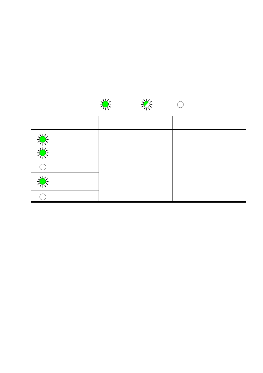
3.1.1 Normal operating status
In normal operating status the following LEDs on CP node 11
will light up:
( lights up; ; flashes; out)
LED
BUS POWER
MODULE STATUS
BUS ERROR
POWER
POWER V
0...3 ERROR
Operating status Error treatment
Normal None
Festo P.BE−CP−FB11−E−EN en 0802d
3−5
Page 54
3. Diagnosis
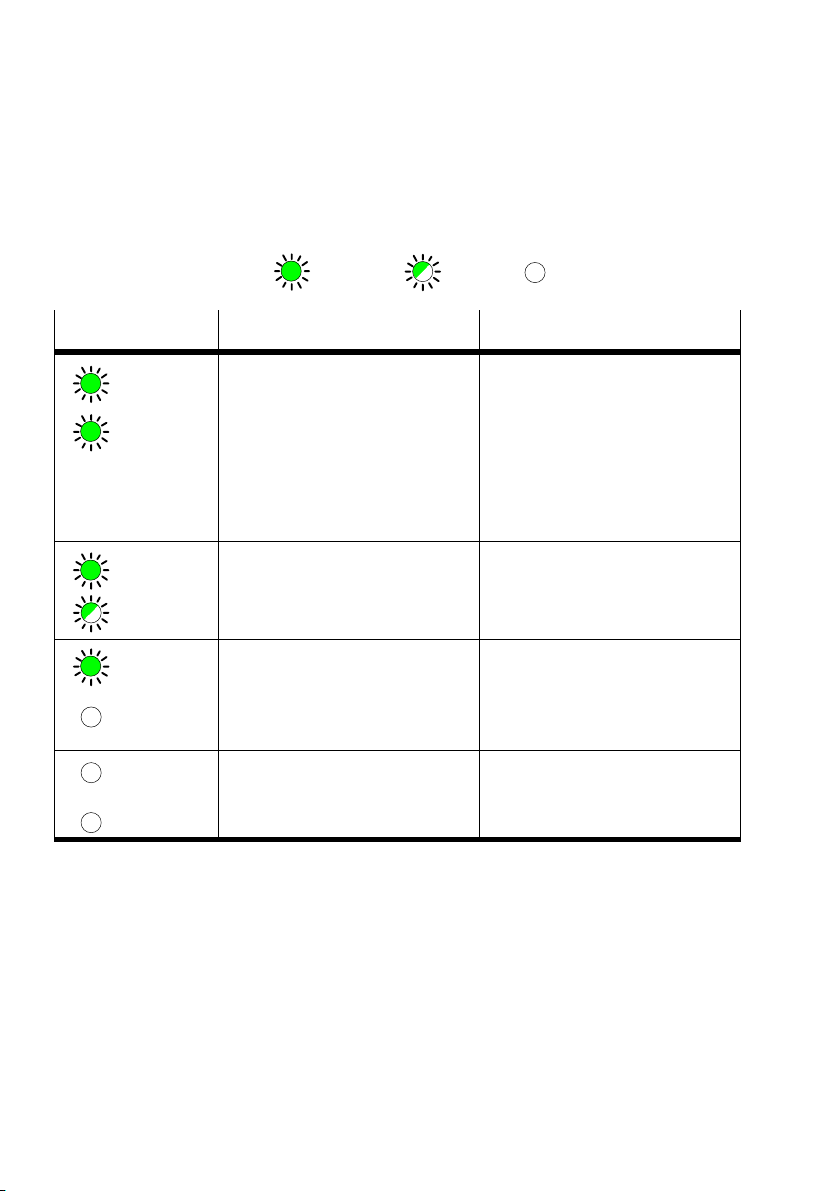
3.1.2Diagnostic operating voltage POWER or POWER V
( lights up; ; flashes; out)
LED
POWER
POWER V
POWER
POWER V
POWER
POWER V
POWER
POWER V
Operating status Error treatment
Operating status normal
or
Operating status normal but
valves do not switch.
Compressed air supply not OK
Pilot exhaust blocked
or
Operating status normal, but
error message on bus LEDs
Operating voltage of the outputs
(pin 2) not in the tolerance range
Operating voltage of the outputs
(pin 2) not applied
or
CP valve terminal or output
module defective
Operating voltage of the elelc
tronics (pin 1) not applied.
or
Hardware error
None
Check the ...
S compressed air supply
S pilot exhaust channels
See error message of bus LEDs
S Check operating voltage of the
outputs (pin 2)
S Check operating voltage of the
outputs (pin 2)
or
S Replace the CP module
S Check the operating voltage
connection
or
S Servicing required
3−6
Festo P.BE−CP−FB11−E−EN en 0802d
Page 55
3. Diagnosis
3.1.3Diagnostic bus LEDs
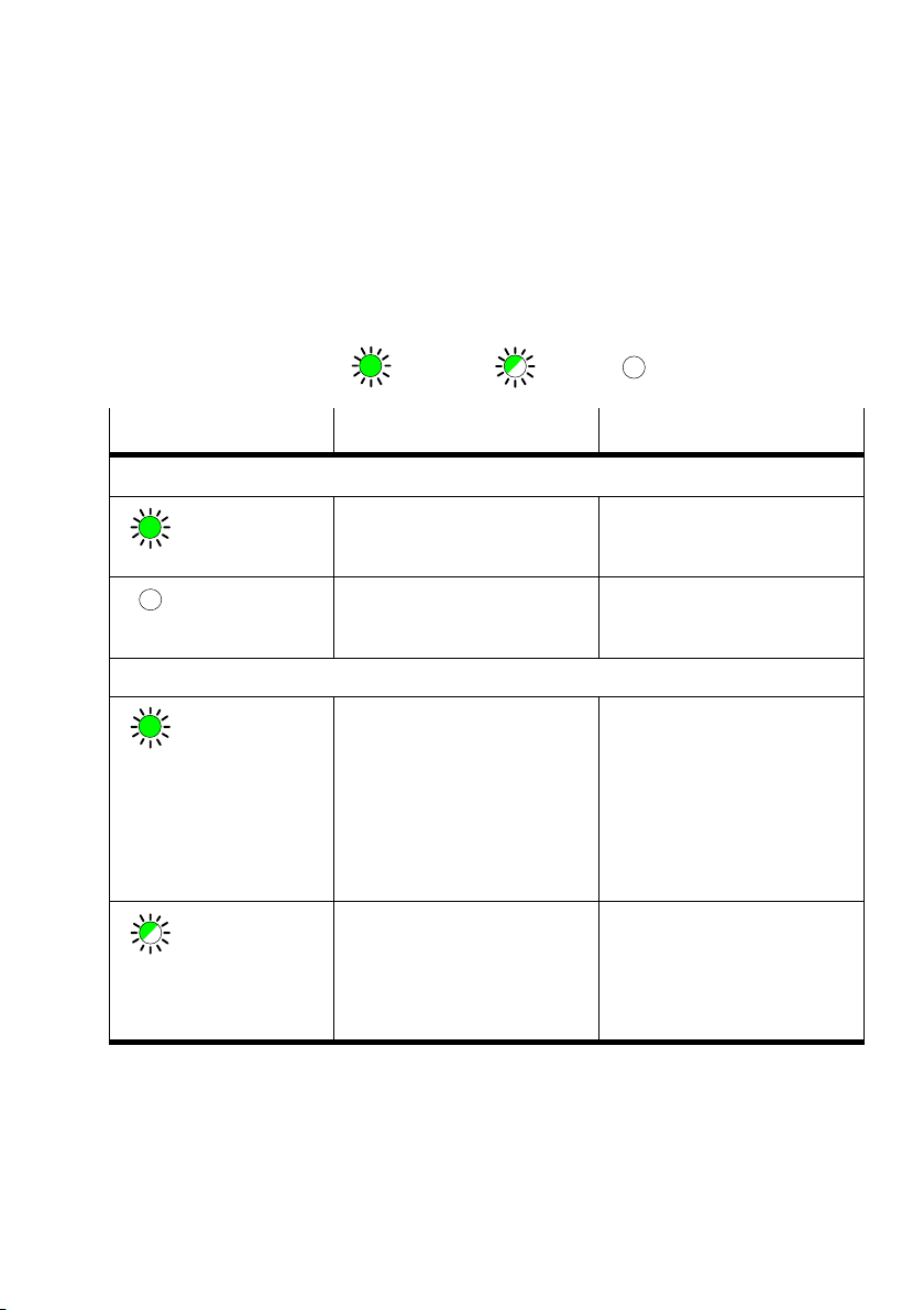
Possible DeviceNet−specific LED displays of the operating
status of the CP node are shown in the following diagram:
LED
BUS POWER
BUS STATUS
( lights up; ; flashes;
Operating status Error treatment
BUS POWER Operating voltage of bus
interface is applied
BUS POWER Operating voltage of bus
interface is not applied
BUS STATUS Operating status normal, data
exchange runs
or
Operating status normal, but
valves do not switch.
Possible causes
Compressed air supply not
OK.
Pilot exhaust blocked
BUS STATUS Lights up once after switching
on (LED test)
Node is ready for data ex
change, but has not yet been
intialized by the master after
having been switched on
out)
None
Check bus operating voltage con
nection (bus plugs pins 2 and 3)
None
Check the ...
S compressed air supply
S pilot exhaust channels
None
S Start communication
Festo P.BE−CP−FB11−E−EN en 0802d
3−7
Page 56
3. Diagnosis
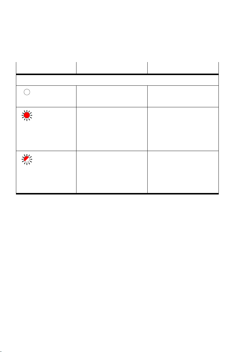
LED Operating status Error treatment
BUS ERROR
BUS ERROR No internal error None
BUS ERROR Non−permitted station number
set, station address assigned
twice or maximum value ex
ceeded
Too many transmission errors
(error counter overrun)
BUS ERROR Lights up once after switching
on (LED test)
Timeout expired, no valid
telegrams received within the
timeout time, bus error, com
munication error or loss of
communication
S Correct station address
S Check cables/plug connectors,
switch on operating voltage
again
S None
S Check connection to PLC
3−8
Festo P.BE−CP−FB11−E−EN en 0802d
Page 57
3. Diagnosis
3.2 Testing the valves
Warning
Before the test:
S Switch off the compressed air supply for the valves.
S In the case of a non−saved string assignment:
Save the existing string assignm
ent.
You can thereby avoid:
undesired or dangerous movements of the actuators
repeated actuation of the SAVE button.
Caution
This test function runs automatically in the CP terminals.
All the valves are switched on/off cyclically.
None of the programmed lockings or f
urther switching
conditions will be taken into account.
Test routineDuring the test routine of the CP valve terminal, all the valves
switched on and off at 1−second intervals.
will be
Festo P.BE−CP−FB11−E−EN en 0802d
3−9
Page 58

3. Diagnosis
Starting the test routine
1.Switch off the power supplies (pins 1 and 2) on the node.
2.Switch off the power supply to the output modules.
3.Remove the DIL switch cover.
4. Note the setting of the address selector switch and the
DIL switch elements.
5.Set DIL switch elements 1
6.Set station number 99.
7.Switch on the power supplies (pins 1 and 2).
8. Starting the test routine.
Set DIL switch elements 1 and 2
and 2 to ON.
to OFF.
Stopping the test routine
1.Switch off the power supplies (pins 1 and 2) on the node.
2.Set the address selector switch and the DIL switch
elements to their origi
When the test routine is finished, switch on the power sup
plies again.
S On the node
S On the output modules
nal positions again.
3−10
Festo P.BE−CP−FB11−E−EN en 0802d
Page 59
3. Diagnosis
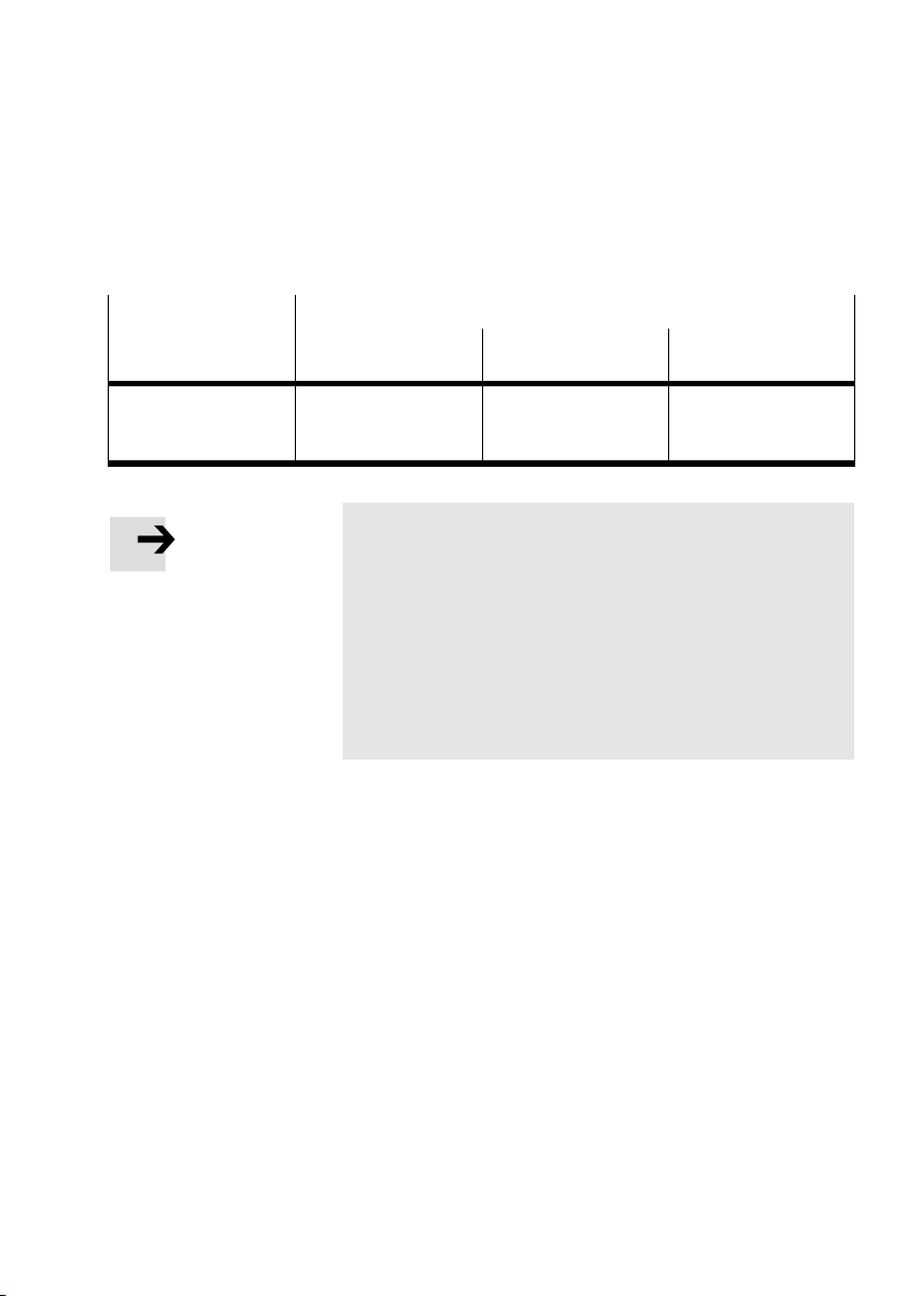
3.3 Reaction to errors in the control system
PLC/protocol Reaction of the CP system
after PLC stop to field bus faults to field bus
interruption
DeviceNet Valves and electric
outputs are reset.
Please note
If all the outputs are reset in the event of a PLC stop, field
bus interruption or field bus fault, the following pneu
matic rules" must be observ
Unilaterally−actuated valves move to the basic position.
Double−solenoid valves remain in the current position.
Mid−position valves move to the mi
(depending on valve type) are pressurized, exhausted or
blocked.
Valves and electric
outputs are reset when
timeout has expired.
ed.
Valves and electric
outputs are reset
immediately.
d−position and
Festo P.BE−CP−FB11−E−EN en 0802d
3−11
Page 60

3. Diagnosis
3.4 Diagnosis on the DeviceNet
The following bus diagnoses are available:
Diagnosis via DeviceNet Scanner
Diagnosis via the Software Configurator
(e.g. RSNetworx, see chapter 3.4.1)
Diagnosis via the
user program (see chapter 3.4.2)
3.4.1Diagnosis via the Software Configurator
1. Make sure that the node is online on the DeviceNet.
2. Double−click the icon of the valve terminal in the Software
Configurator (e.g. RSNetworx).
3. Click
4. Double−click the parameter line Status word".
Further information can be found
the rider Device Parameters".
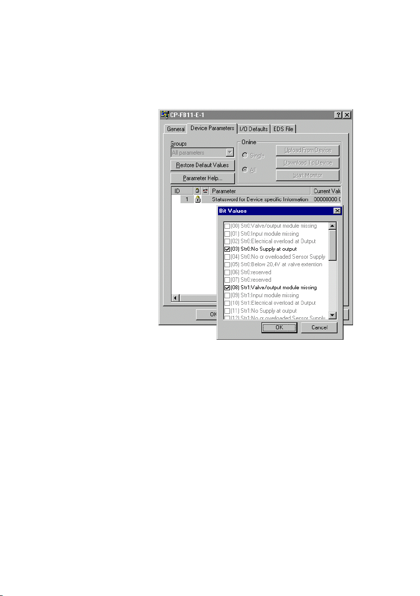
Detailed information will be shown (see Fig.3/2)
in table Fig.3/3.
3−12
Festo P.BE−CP−FB11−E−EN en 0802d
Page 61
3. Diagnosis
Festo P.BE−CP−FB11−E−EN en 0802d
Fig.3/2: Display of detailed information on diagnosis
(explanations see text)
3−13
Page 62

3. Diagnosis
The following table shows the composition of the diagnostic
information of the strings:
Bit
(string 0)
0 8 16 24 Valve/output
1 9 17 25 Input module
2 10 18 26 Electric overload
3 11 19 27 No supply at
4 12 20 28 No or overloaded
5 13 21 29 Below 20.4 V at
6 14 22 30 Reserved not used
7 15 23 31 Reserved not used
Bit
(string 1)
Bit
(string 2)
Bit
(string 3)
Comment in EDS
file
module missing
missing
at output
output
sensor supply
valve extension
Explanation
CP connection interrupted at
output module
CP connection interrupted at
input module
Short circuit/overload at out
put module (see chapter 3.5)
Load voltage failure at output
module
Operating voltage failure at
input module or sensors, short
circuit/overload of sensor sup
ply (see chapter 3.6)
Load voltage of valve coils
< 20.4 V
Fig.3/3:Table with explanation of the diagnostic information
3.4.2Diagnosis via user program
3−14
If the separate communication connection Strobed I/O" is
configured for the CP system (see Fig.2/5), the diagnostic
information from the above table (Fi
g.3/3) is then available
for the user program. The data from the Strobed I/O connec
tion can be placed in the input file or in the M1 file of the
con
troller.
Festo P.BE−CP−FB11−E−EN en 0802d
Page 63
3. Diagnosis
3.5 Short circuit/overload at an output module
In the event of a short circuit or overload:
all the digital outputs of a string will be switched off,
the green LED Diag" on the output
module will flash
quickly.
Please note
The outputs cannot be used again until the short circuit or
overload has been eliminated and the error deleted.
Deleting the error
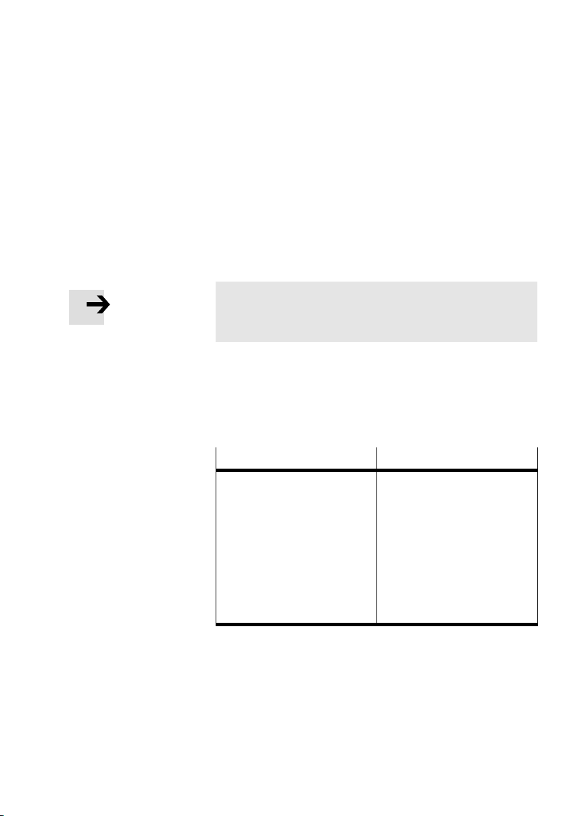
You can delete the error by resetting all eight outputs. You
can do this in one of the following ways:
Possibilities
S Set all the outputs of the
output module to logical 0"
(RESET)
or
S Briefly interrupt the CP
connection at the CP output
module
or
S Briefly interrupt the operating
voltage for the CP system at
the field bus node
Explanation
Manually or automatically in
the program
Outputs on the output
module will be reset auto
matically.
All outputs of the CP system
will be reset automatically.
Festo P.BE−CP−FB11−E−EN en 0802d
The outputs can then be used again. If the short circuit/over
load still exists, the outputs will be switched off again.
3−15
Page 64
3. Diagnosis
3.6 Short circuit in the sensor supply at an input module
In the event of a short circuit or overload:
the sensor supply for all inputs of the module will be
switched off
the green LED Diag" on th
quickly.
Please note
The outputs cannot be used again until the short circuit
or overload has been eliminated and the error deleted.
e input module will flash
Deleting the error
You can delete the error in one of the following ways:
S briefly interrupt the CP connection at the CP input module
or
S briefly interrupt the operating v
at the field bus node.
The inputs can then be used again. If the short circuit/over
load still exists, the erro
r will be shown again.
oltage for the CP system
3−16
Festo P.BE−CP−FB11−E−EN en 0802d
Page 65

Technical appendix
Appendix A
A−1Festo P. BE−CP−FB11−E−EN en 0802d
Page 66

A. Technical appendix
Contents
A. Technical appendix A−1 . . . . . . . . . . . . . . . . . . . . . . . . . . . . . . . . . . . . . . . . . . . . .
A.1 Technica
A.2DeviceNet objects A−5 . . . . . . .
A.2.1 Festo Output Object: Class Code
A.2.2 Festo Input Object: Class Code 100dA−5 . . . . .
A.2.3 Festo Diagnostic Object: Class Code 100dA−6 . . . . . . . . .
A.3 Accessories A−7 . . . . . . . . . . . . . . . . . . . . . . . . . . . .
l specifications field bus node CP FB11−E A−3 . . . . . . . . . . . . . . . . . . . . .
. . . . . . . . . . . . . . . . . . . . . . . . . . . . . . . . . . . . . . .
100dA−5 . . . . . . . . . . . . . . . . . . . . . . . . . . . . . .
. . . . . . . . . . . . . . . . . . . . . . . . . .
. . . . . . . . . . . . . . . . . . . . . . . .
. . . . . . . . . . . . . . . . . .
A−2
Festo P.BE−CP−FB11−E−EN en 0802d
Page 67
A. Technical appendix
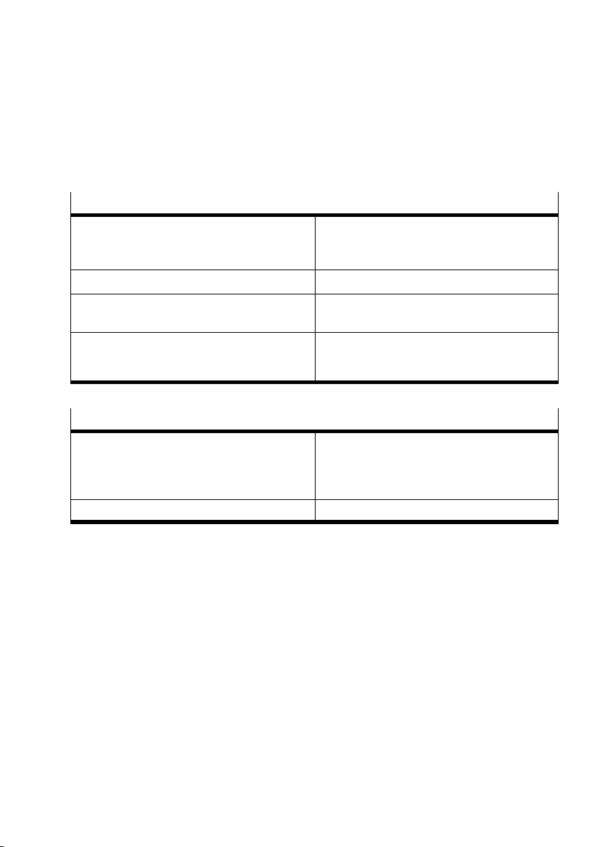
A.1 Technical specifications field bus node CP FB11−E
General
Temperature range
Operation
Storage/transport
Relative humidity 95 %, non−condensing
− 5 °C ... + 50 °C
− 20 °C ... + 70 °C
Protection class as per EN 60529 plug connector
inserted or provided with protective cap
Protection against electric shock
(protection against direct and indirect contact as
per IEC/DIN EN 60204−1)
IP65
by means of PELV circuits
(ProtectiveExtra−Low Voltage)
Operating voltage for the bus interface
Pin 2, 3; bus interface
Rated value not protected against incorrect
polarity
Tolerance
Current consumption (at 24 V) 50 mA
External fuse required
24 V DC
+ 4 % − 52 % (V
max
25 V, V
min
11.5 V)
Festo P.BE−CP−FB11−E−EN en 0802d
A−3
Page 68
A. Technical appendix
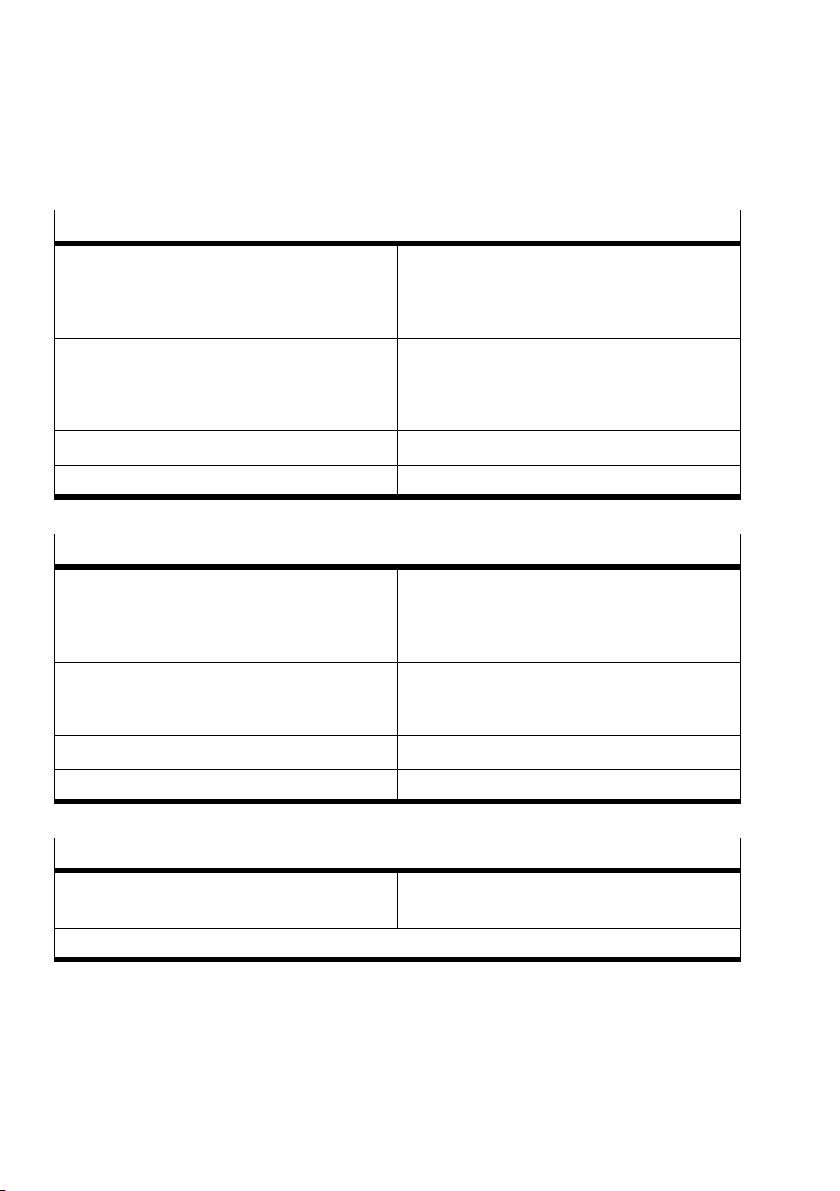
Operating voltage for the electronics and the input modules
Pin 1
Power supply connection
Rated value
Tolerance
Current consumption
Pin 1 node FB11−E
Complete electronics of the CP system
Residual ripple 4 Vpp (within tolerance)
Bridging time during drop in logic voltage 20 ms
24 V DC
20.4...26.4 V
250 mA
See manual CP system", table of current
consumption
Load voltage for solenoid valves on CP valve terminal
Pin 2
Power supply connection
Rated value
Tolerance
24 V DC
20.4...26.4 V
Current consumption
Pin 2 node FB11−E Sum of all switched−on CP solenoid valves;
Residual ripple 4 Vpp (within tolerance)
Bridging time during drop in logic voltage 20 ms
see manual CP pneumatics"
Electromagnetic compatibility
Interference emitted
Immunity against interference
1)
The component is intended for industrial use.
A−4
Tested as per DIN EN 61000−6−4 (industry)
Tested as per DIN EN 61000−6−2 (industry)
Festo P.BE−CP−FB11−E−EN en 0802d
1)
Page 69
A. Technical appendix
A.2 DeviceNet objects
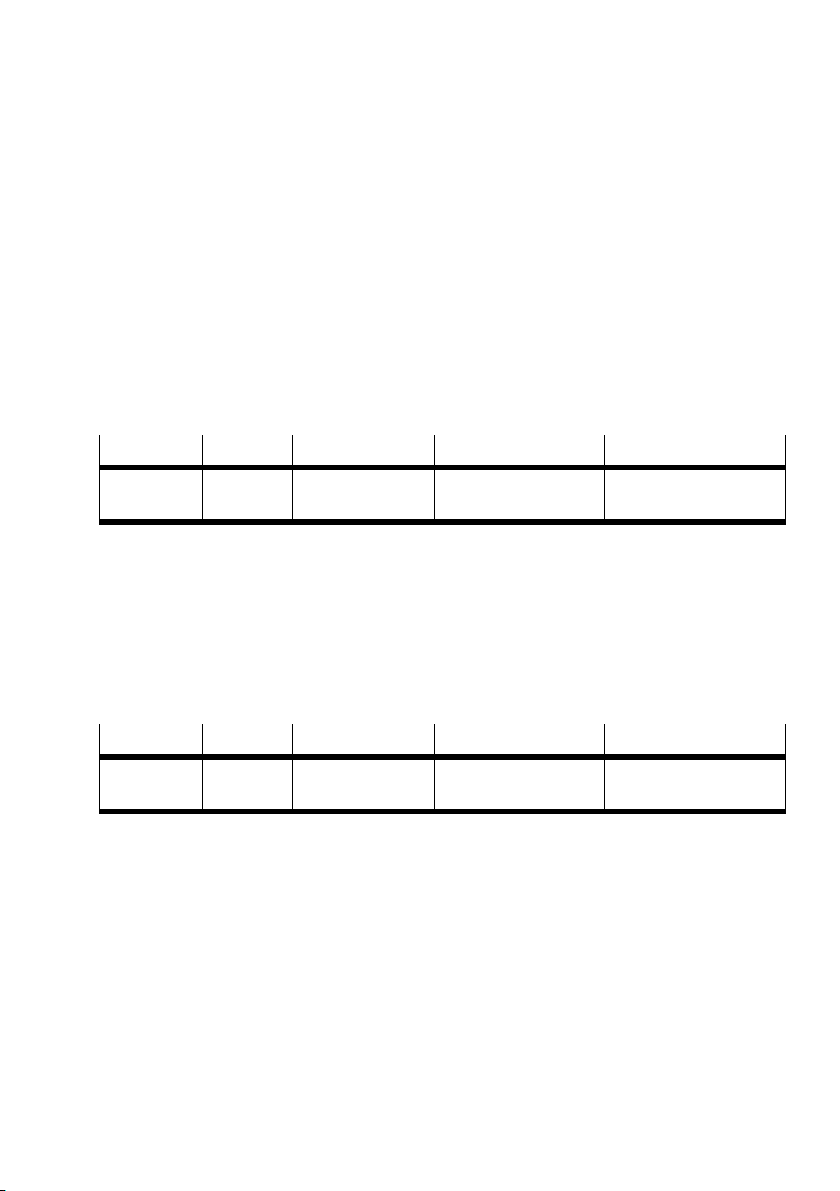
A.2.1 Festo Output Object: Class Code 100d
Vendor−specific object which contains the output information.
Festo Output Object Class Attributes
Attributes
3 Get/set Output bytes Byte
Access Name Type Value
(2 bytes per string)
A.2.2 Festo Input Object: Class Code 100d
Vendor−specific object which contains the input information.
Festo Input Object Class Attributes
Attributes
3 Get Input bytes Byte
Access Name Type Value
(2 bytes per string)
Festo P.BE−CP−FB11−E−EN en 0802d
A−5
Page 70
A. Technical appendix
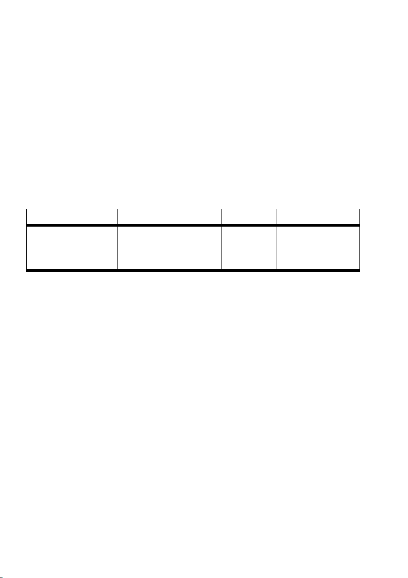
A.2.3 Festo Diagnostic Object: Class Code 100d
By means of this vendor−specific object (class code 102d) you
can receive the device−related diagnostic information for the
CP system. The information
tic byte for each string:
Festo Diagnostic Object Class Attributes
is grouped together in a diagnos
Attributes
3 Get Diagnostic bytes Byte
Access Name Type Value
(4 bytes)
1. Byte for string 0
2. Byte for string 1
3. Byte for string 2
4. Byte for string 3
A−6
Festo P.BE−CP−FB11−E−EN en 0802d
Page 71

A. Technical appendix
A.3 Accessories
} www.festo.com/catalogue
Festo P.BE−CP−FB11−E−EN en 0802d
A−7
Page 72

A. Technical appendix
A−8
Festo P.BE−CP−FB11−E−EN en 0802d
Page 73

Index
Appendix B
B−1Festo P. BE−CP−FB11−E−EN en 0802d
Page 74

B. Index
Contents
B. Index B−1 . . . . . . . . . . . . . . . . . . . . . . . . . . . . . . . . . . . . . . . . . . . . . . . . . . . . . . . . .
B−2
Festo P.BE−CP−FB11−E−EN en 0802d
Page 75

B. Index
A
Abbreviations
Product−specific XII. . . . . . . . . . . . . . . . . . . . . . . . . . . . . . . .
Accessories A−7. . . . . . .
Addressing
Address assignment of the CP system 2−4. . . . . .
Example for scanner 1747−SDN 2−18. . . . . . . . . . . . . . . . . . .
On the DeviceNet 2−7. . . . . .
. . . . . . . . . . . . . . . . . . . . . . . . . . . . . . .
. . . . . . . .
. . . . . . . . . . . . . . . . . . . . . . . . .
B
Bus LEDs
Diagnosis 3−7. . . . . . . . . . . . . . . . . . . . . . . . . . . . . . . . . . . . .
C
Festo P.BE−CP−FB11−E−EN en 0802d
Cables
Field bus1−12. . . . . . . . . . . . . . . . . . . . . . . . . . . . . . . . . . . . .
Operating voltage1−12. .
Compatibility 1−8. . . . . . . . . . . . . . . . . .
Configuration list 2−4. . . . . . . . . . . . . . . . . . . . . . . . . . .
Compiling 2−4. . . . . . . . . . . . . . . . . . . . . . . . . . . . . . . . . . . . .
Connecting
CP
modules 1−10. . . . . . . . . . . . . . . . . . . . . . . . . . . . . . . . . . .
Operating voltage1−10. . . . . . .
Connection instructions1−17. . . . . . . . . . . . . . . . . .
CP system
Operating voltage2−3. . . . . . . . . . . . . . . . . . . . . . . . . . . . . . .
Preparations for commissioning 2−3. . . . . . . . . . . . . . . . . . .
. . . . . . . . . . . . . . . . . . . . . . . . . . . .
. . . . . . . . . . . . . . . . . .
. . . . . .
. . . . . . . . . . . . . . . . . . . . . . .
. . . . . . . . .
B−3
Page 76

B. Index
D
Data transmission
Interface 1−12, 1−15. . . . . . . . . . . . . . . . . . . . . . . . . . . . . . . .
Designated use VII. . . .
DeviceNet
Addressing 2−4. . . . . . . . . . . . . . .
Diagnosis
Bus LEDs 3−7. . . . . . . . . . . . . . . . . . . . . . . .
On the DeviceNet 3−12. . . . . . . . . . . . . . . . . . . . . . . . . . . . . .
Operating voltage LEDs 3−6. . . . . . . . . . . . . . . . . . . . . . . . . .
. . . . . . . . . . . . . . . . . . . . . . . . . . . . . .
. . . . . . . . . . . . . . . . . . . . .
. . . . . . . . . . . . . .
E
EDS library 2−8. . . . . . . . . . . . . . . . . . . . . . . . . . . . . . . . . . . . . .
F
B−4
Field bus
Connecting the CP node1−12. . . . . . . . . . . . . . . . . . . . . . . . .
Interface 1−12. . . . . . . . .
Station number 1−5. . . . . . . . . . . . . . . . . .
Field bus interface
Pin assignment 1−15. . . . . . . . . . . . . . . . . . . . . .
Fitting
Terminating resistor 1−18. . . . . . . . . . . . . . . . . . . . . . . . . . . .
. . . . . . . . . . . . . . . . . . . . . . . . . . . .
. . . . . . . . . . . . . . .
. . . . . . . . . .
I
Important user instructions IX. . . . . . . . . . . . . . . . . . . . . . . . . .
Festo P.BE−CP−FB11−E−EN en 0802d
Page 77

B. Index
L
LEDs 3−3. . . . . . . . . . . . . . . . . . . . . . . . . . . . . . . . . . . . . . . . . . .
Diagnosis 3−6, 3−7.
. . . . . . . . . . . . . . . . . . . . . . . . . . . . . . . .
N
Node address
Address selector switch 1−5. . . . . . . . . . . . . . . . . . . . . . . . . .
Nominal/actual configuration 2−4. . .
Notes on this manual VIII. . . . . . . . . . . . . . . . . . . . . . . .
. . . . . . . . . . . . . . . . . . . .
. . . . . .
O
Operating status3−5. . . . . . . . . . . . . . . . . . . . . . . . . . . . . . . . .
Operating voltage
Bus interface 2−3.
CP system 2−3. . . . . . . . . .
. . . . . . . . . . . . . . . . . . . . . . . . . . . . . . . . . .
. . . . . . . . . . . . . . . . . . . . . . . . . . .
Festo P.BE−CP−FB11−E−EN en 0802d
P
Pictograms X. . . . . . . . . . . . . . . . . . . . . . . . . . . . . . . . . . . . . . . .
POWER LEDs
Diagnosis 3−6. . .
. . . . . . . . . . . . . . . . . . . . . . . . . . . . . . . . . .
B−5
Page 78

B. Index
S
Save
String assignment 2−3. . . . . . . . . . . . . . . . . . . . . . . . . . . . . .
Screening/shield
Field bus1−15. . . .
Service IV. . . . . . . . . . . . . . .
Setting
Compatibility 1−8. . . . . . . . . . . . . . . . .
Field bus baud rate1−7. . . . . . . . . . . . . . . . . . . . . . . . . . .
Station number
Address selector switch 1−5. . . . . . . . . . . . . . . . . . . . . . . . . .
String assignment
Save2−3. . . .
Switching on
Voltage2−6. . . . .
Switching status
Valves 3−9. . . . . . . . .
. . . . . . . . . . . . . . . . . . . . . . . . . . . . . . . . .
. . . . . . . . . . . . . . . . . . . . . . . . . . .
. . . . . . . . . . . . . . . . .
. . . . . . . . . . . . . . . . . . . . . . . . . . . . . . . . . . . . .
. . . . . . . . . . . . . . . . . . . . . . . . . . . . . . . . . .
. . . . . . . . . . . . . . . . . . . . . . . . . . . . . . .
. .
B−6
T
Target group VII. . . . . . . . . . . . . . . . . . . . . . . . . . . . . . . . . . . . .
Technical specifications A−3. .
Test routine for valves 3−9. . . . . . . . . . . . . . .
Text markings X. . . . . . . . . . . . . . . . . . . . . . . . . . . . . . . .
. . . . . . . . . . . . . . . . . . . . . . . . . .
. . . . . . . . . . . . . .
. . . . . .
Festo P.BE−CP−FB11−E−EN en 0802d
 Loading...