

Festo Compact Vision System SBO-Q Series, Compact Vision System SBOI-Q Series, Compact Vision System SBOC-Q Series User Instructions

Kompaktkamerasystem SBO..−Q
Compact Vision System SBO..−Q
Kurzübersicht
Brief overview
Typ SBO..−Q−...
Type SBO..−Q−...
Deutsch
English
Españo
Français
Italiano
Svenska
705 507
0608NH

Deutsch 3 . . . . . . . . . . . . . . . . . . . . . . . . . . . . . . . . . . . . . . . . . . .
English 15 . . . . . . . . . . . . . . . . . . . . . . . . . . . . . . . . . . . . . . . . . . . .
Español 27 . . . . . . . . . . .
. . . . . . . . . . . . . . . . . . . . . . . . . . . . . . . .
Français 39 . . . . . . . . . . . . . . . . . . . . . . . . . . . . . . . . . . . . . . . . . . .
Italiano 51 . . . . . . . . . . . . . . . . . . . . . . . . . . . . . . . . . . . . . . . . . . . .
Svenska 63 . . . . . . . . . . . . . . . . . . . . . . . . . . . . . .
Edition:
0608NH
. . . . . . . . . . . . .
Original: de
© (Festo AG&Co., D73726 Esslingen, Germany, 2006)
Internet: http://www.festo.com
E−Mail: service_international@festo.com
Festo P.BE−K−SBO−Q 0608NH 2

1 BenutzerhinweiseDeutsch
Hinweis
Diese Kurzübersicht ist Bestandteil des Dokumen
tationspaketes Typ P.BE−SBO−Q−UDOK. Sie dient nur zur
Erstinformation und ersetzt nicht die vollständige Do
kumentation, die als PDF−Datei auf der mitgelieferten
CD−ROM des Dokumentationspaketes enthalten ist
(siehe Tabelle).
S Beachten Sie unbedingt die Informationen und
sicherheitstechnischen Hinweise in der vollständigen
Beschreibung des Kompaktkamerasystems.
S Bitte wenden Sie sich bei technischen
Ihren lokalen Service von Festo oder an folgende
E−Mail Adresse: service_international@festo.com
Problemen an
Inhalt der CD−ROM
Beschreibung des Kompaktkamera
systems TypSBO..−Q−...
Montage
Installation
Hinweise zur Inbetriebnahme
Diagnose
1)
= <Teilenummer> + <Sprachkennung>.
Festo P.BE−K−SBO−Q 0608NH Deutsch 3
Sprache Dateiname
Deutsch
Englisch
705505
705506d1g1
1)

Weitere Informationen finden Sie im Hilfesystem der
Konfigurationssoftware Festo CheckKon.
1.1 Bestimmungsgemäße Verwendung
Das Kompaktkamerasystem Typ SBO..−Q−... ist zum Einbau
in eine Maschine bzw. eine automatisierungstechnische
Anlage bestimmt. Es dient zur Analyse von Prüfteilen auf
Qualität und Position.
Die Inbetriebnahme und Bedienung erfolgt über die Ether
net−Schnittstelle mit den Softwarepaketen CheckKon und
CheckOpti.
Festo P.BE−K−SBO−Q 0608NH Deutsch4
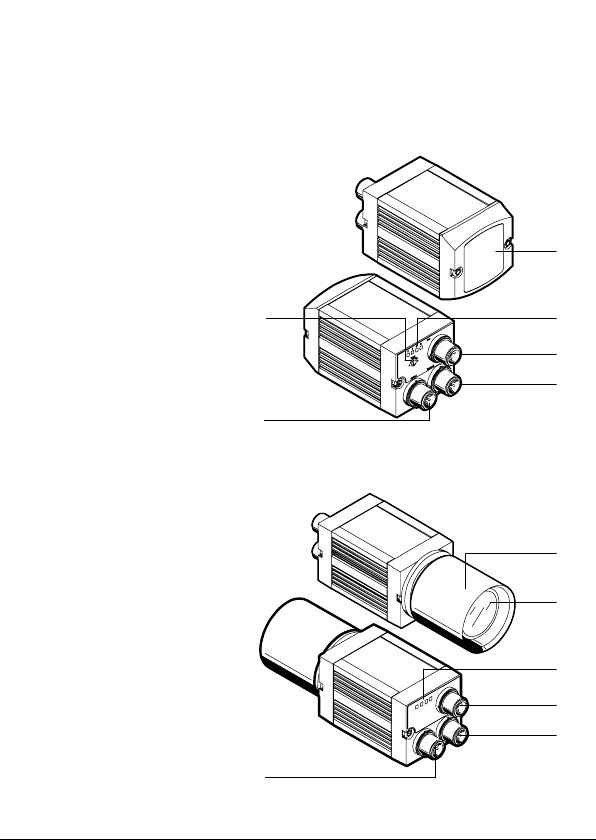
2 Anschluss− und Anzeigeelemente
Typ SBOI−Q−...
1 Integriertes Objektiv
und LED−Beleuch
tung
2 Status−LEDs
3 CAN−Schnittstelle
4 Ethernet−Schnitt
stelle
5 Betriebsspannungs
versorgung und
digitale E/As
6 Fokusverstellung
Typ SBOC−Q−...
1 Schutztubus
2 Objektiv (Zubehör)
3 Status−LEDs
4 CAN−Schnittstelle
5 Ethernet−Schnitt
stelle
6 Betriebsspannungs
versorgung und
digitale E/As
6
5
1
2
3
4
1
2
3
4
6
Festo P.BE−K−SBO−Q 0608NH Deutsch 5
5

Status−LEDs Zustand Beschreibung
schaft
A Betriebs−
bereit
schaft
LED blinkt grün Gerät ist betriebsbereit
LED leuchtet rot Initalisierung läuft
LED ist aus Unbestimmter Zustand, z.B.
Betriebsspannung liegt nicht an
B Ethernet−
Traffic
LED blinkt grün Ethernet−Datenverkehr (Traffic)
LED ist aus Kein Ethernet−Datenverkehr
(No Traffic)
C Aktivität
LED leuchtet rot Fehler
LED blinkt rot Warnung
LED leuchtet gelb Gerät ist betriebsbereit, Aus
wertung kann gestartet werden
LED ist aus Auswertung läuft
D Ausgabe
1)
LED leuchtet rot Letzte Auswertung ergab
Schlechtteil
LED leuchtet gelb Letzte Auswertung ergab
Gutteil
LED ist aus Kein Ergebnis
1) Die Funktion der Ausgabe−LED ist über Systemparameter konfigu
rierbar, die angegebene Beschreibung entspricht der Standard−
Konfiguration.
Festo P.BE−K−SBO−Q 0608NH Deutsch6

3 Hinweise zur Montage und Installation
Warnung
S Schalten Sie vor Montage−, Installations− und
Wartungsarbeiten die Betriebsspannungsversorgung
der Elektronik aus.
S Verwenden Sie ausschließlich Stromquellen, die eine
sichere elektrische Trennung der Betriebsspannung
nach IEC/DIN EN 60204−1 gewährleisten. Berücksich
tigen Sie zusätzlich die allgemeinen Anforderungen
an PELV−Stromkreise gemäß IEC/DIN EN 60204−1.
S Verwenden Sie geschirmte Kabel und Steckverbinder,
die die durchgängige Kontaktierung des Schirms
Kompaktkamerasystem gewährleistet.
S Legen Sie den Schirm der Kabel niederohmig auf Erd
potenzial.
S Das Gerät enthält elektrostatisch gefährdete Bau
elemente. Berühren Sie deshalb keine Bauelemente.
Beachten Sie die Handhabungsvorschriften für elek
trostatisch gefährdete Bauelemente.
S Gehäuse nicht öffnen.
Vorsicht
S Stellen Sie sicher, dass bei der Betriebsspannungs
versorgung die Toleranz von ±10 % eingehalten wird.
S Sichern Sie die Versorgung des Kompaktkamerasy
stems extern ab mit einer Feinsicherung flink, 2 A.
zum
Festo P.BE−K−SBO−Q 0608NH Deutsch 7

Auf der Unterseite des Kompaktkamerasystems befindet
sich ein Montageprofil mit Schwalbenschwanz−Führung.
Zur Befestigung dienen folgende Adapterbausätze:
Adapterbausatz
Typ SBOA−HMSV−39 Zur Montage mit anschraubbarer
Typ SBOA−HMSV−40 Zur Montage mit anschraubbarer
Typ SBOA−HMSV−41 Zur Befestigung an handelsübliche
Beschreibung
Adapterplatte (im Adapterbausatz
enthalten)
Adapterplatte, z.B. Adapterplatte Typ
HMSV−11 (nicht im Adapterbausatz
enthalten)
Foto−/
Videostative (Adapter mit Innenge
winde G1/4)
Festo P.BE−K−SBO−Q 0608NH Deutsch8

Folgendes Bild zeigt die Montage mit dem Adapterbausatz
Typ SBOA−HMSV−39 am Beispiel des Kompaktkamera−
systems Typ SBOI−...:
Schwalbenschwanz des Kompaktkamerasystems
1
2 Spannelemente
3 Bohrung für Zylinderschraube M5x16 mit Zentrierhülse
4 Adapterplatte
1
2
3
4
Festo P.BE−K−SBO−Q 0608NH Deutsch 9
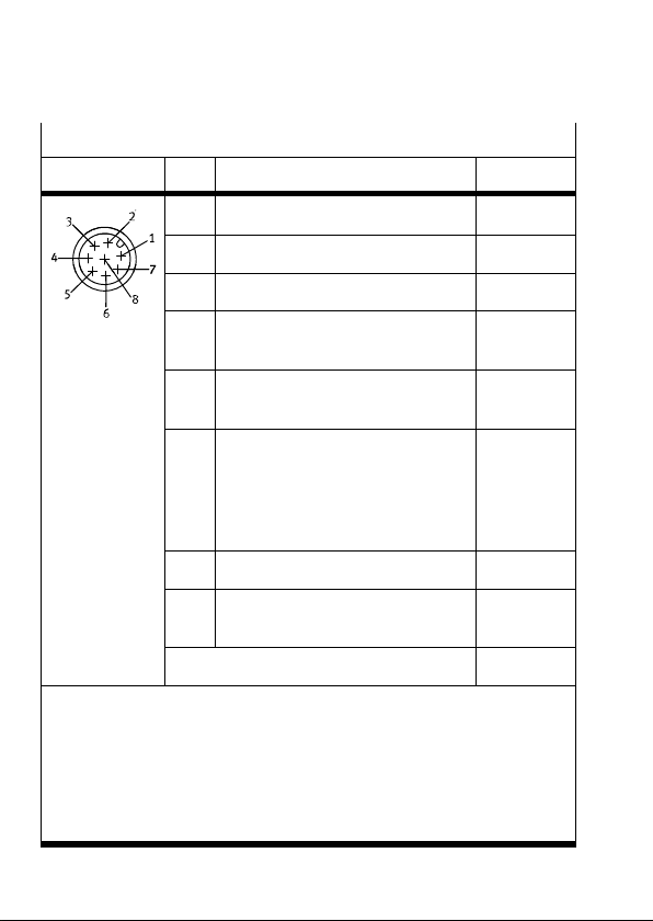
Betriebsspannungsversorgung und digitale E/As
M12−Stecker Pin Beschreibung
1 E0 2): Trigger−Signal weiß (WH)
2 + 24 V DC (Toleranz: ±10 %) braun (BN)
3 Reserviert (nicht anschließen) grün (GN)
Farbe
1)
4 A1: Letzte Auswertung ergab
5 E1: Eingänge−Übernehmen−Signal
3)
Gutteil
und bei Fehler Quittierung
2)
6 A0: Ready
gelb (YE)
grau (GY)
rosa (PK)
1−Signal: Gerät betriebsbereit
0−Signal: Gerät noch nicht be
triebsbereit (z. B. Auswertung
läuft, Systemfehler)
7 0 V blau (BU)
8 A2: Letzte Auswertung ergab
Schlechtteil
3)
Metallumhüllung: Schirm (Shield)
rot (RD)
4)
1) Adernfarben des Originalskabels SMI−M12−8GD−...−PU
2) Die Signal Pegel/Flanken sind über Systemparameter
konfigurierbar, die angegebene Beschreibung entspricht der
Standardkonfiguration.
3) Die Funktion ist über Systemparameter konfigurierbar, die
angegebene Beschreibung entspricht der Standardkonfiguration.
4) Kabelschirm niederohmig auf Erdpotenzial legen
Festo P.BE−K−SBO−Q 0608NH Deutsch10

Hinweis
43
3
Verwenden Sie zum Anschließen der Betriebsspan
nungsversorgung und der Ein− und Ausgänge nur das
Originalkabel SIM−M12−8GD−2−PU oder
SIM−M12−8GD−5−PU von Festo.
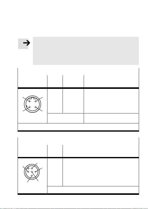
Ethernet: Ethernet−Schnittstelle
M12−Stecker 1)Pin Signal Beschreibung
1
2
1
TD+
2
RD+
3
TD−
4
RD−
Sendedaten+
Empfangsdaten+
Sendedaten−
Empfangsdaten−
Metallumhüllung Schirm (Shield)
1)
d−codiert
Bus: CAN−Schnittstelle
M12−Stecker Pin Signal
1
1
2
3
4
5
n.c. (not connected)
2
n.c. (not connected)
3
GND
4
CAN_H
5
CAN_L
Metallumhüllung, Schirm (Shield)
Festo P.BE−K−SBO−Q 0608NH Deutsch 11

4 Hinweise zu Inbetriebnahme und Betrieb
Führen Sie die Inbetriebnahme mit dem Softwarepaket
CheckKon durch (siehe auch Hilfe zu CheckKon).
4.1 Installation und Start von CheckKon
Hinweis
Zur Installation von CheckKon sind Administra
torrechte erforderlich.
CheckKon wird mit einem Installationsprogramm auf Ihrem
PC installiert.
So installieren Sie CheckKon und SBO−DeviceManager von
CD−ROM:
1. Schließen Sie alle Programme.
2. Legen Sie die CD Festo CheckKon in Ihr CD−ROM Lauf
werk ein. Wenn Auto−Run auf Ihrem System aktiviert
ist, startet die Installation automatisch und Sie können
die Schritte 3 und 4 überspringen.
3. Wählen Sie
4. Geben Sie D:\setup ein (ersetzen Sie ggf. D durch den
Buchstaben Ihres CD−ROM−Laufwerks).
Das Programm Setup installiert die Anwendugnen
CheckKon und SBO−DeviceManager.
5. Folgen Sie den Anweisungen auf dem Bildschirm.
[Ausführen] im Start−Menü.
Festo P.BE−K−SBO−Q 0608NH Deutsch12

4.2 Einstellen der Optik
Objekt fokussieren
Typ SBOI−... Typ SBOC−... mit Standard−
Objektiv von Festo
S Drehen Sie mit einem
Schraubendreher den
Fokusversteller an der
Rückseite des
Kameragehäuses.
S Lösen Sie die Klemmschraube
am Objektiv.
S Drehen Sie den Fokusring, um
ein Objekt zu fokussieren.
S Ziehen Sie die Klemmschraube
wieder leicht an.
Blende einstellen
Typ SBOI−... Typ SBOC−... mit Standard−
S Lösen Sie die Klemmschraube
Festo P.BE−K−SBO−Q 0608NH Deutsch 13
Objektiv von Festo
am Objektiv.
S Drehen Sie den Blendenring,
um die Blende einzustellen.
S Ziehen Sie die Klemmschraube
wieder leicht an.

4.3 Triggersignal
Das Triggersignal wird über den Eingang E0 zugeführt.
Die Triggerbedingung ist erfüllt, wenn ein 1−Signal (Flanke)
an E0 erkannt wird.
Das Triggersignal dient zum Start der Auswertung eines
Prüfteils mit Hilfe der Kompaktkamera.
Solange die Auswertung andauert, erlischt die LED (C) und
am Ausgang A0 liegt ein 0−Signal an.
Hinweis
Die Signal Pegel/Flanken des Eingangs E0 sind über
Systemparameter konfigurierbar. Die angegebene
Beschreibung entspricht der Standard−Konfiguration.
Hinweis
Weitere Informationen zum Betrieb des Kompakt
kamerasystems finden Sie im Hilfesystem von
CheckKon.
Festo P.BE−K−SBO−Q 0608NH Deutsch14

1 User instructionsEnglish
Note
This brief overview is part of the documentation
package type P.B E−SBO−Q−U DOK. It serves only as
initial information and does not replace the complete
documentation, which is contained as a PDF file on
the CD ROM supplied with the documentation package
(see table).
S It is essential that you observe the information and
safety instructions in the complete manual for
the
the Compact Vision System.
S Please consult your local Festo repair service or write
to the following e−mail address if you have any
technical problems: service_international@festo.com
Contents of the CD ROM
Description for the Compact Vision
System typeSBO..−Q−...
Assembly
Installation
Instructions on commissioning
Diagnosis
1)
= <part number> + <language code>.
Festo P.BE−K−SBO−Q 0608NH English 15
Language File name
German
English
705505
705506d1g1
1)

Additional information can be found in the help system of
the configuration software Festo CheckKon:
1.1 Intended use
The Compact Vision System type SBO..−Q−... has been
designed for fitting in a machine or into an automated
system. It allows inspection parts to be analyzed with
respect to quality and position.
The commissioning and operation
are carried out via the
Ethernet interface with the software packages CheckKon
and CheckOpti.
Festo P.BE−K−SBO−Q 0608NH English16

2 Connection and display components
Type SBOI−Q−...
1 Integrated lens and
LED lighting
2 Status LEDs
3 CAN interface
4 Ethernet interface
5 Power supply and
digital I/Os
6 Focus adjustment
6
1
2
3
5
Type SBOC−Q−...
4
1 Protective tubing
2 Lens (accessories)
1
3 Status LEDs
4 CAN interface
2
5 Ethernet interface
6 Power supply and
digital I/Os
6
Festo P.BE−K−SBO−Q 0608NH English 17
3
4
5

Status LEDs
Status Description
A Readiness
to operate
LED flashes green Device is ready to operate
LED illuminated
Initialization is running
in red
LED is off Undefined status, e.g.
operating voltage not applied
B Ethernet
traffic
LED flashes green Ethernet data traffic
LED is off No Ethernet data traffic
(No traffic)
C Activity
LED illuminated
Error
in red
LED flashes red Warning
LED illuminated
in yellow
Device is ready to operate,
and evaluation can begin
LED is off Evaluation in progress
D Output
1)
LED illuminated
in red
LED illuminated
in yellow
Last evaluation resulted in
reject part
Last evaluation resulted in
good part
LED is off No result
1) The function of the output LED can be configured via the system
parameters. The given description corresponds to the standard
configuration.
Festo P.BE−K−SBO−Q 0608NH English18

3 Notes on connecting and installation
Warning
S Before carrying out connecting, installation and
maintenance work, always switch off the power
supply for the electronics.
S Use only power sources which guarantee reliable
electrical isolation of the operating voltage in accord
ance with IEC/DIN EN 60204−1. Observe also the gen
eral requirements for PELV circuits in accordance with
IEC/DIN EN 60204−1.
screened cables and plug connectors which
S Use
guarantee continuous contact between the screen
and the Compact Vision System.
S Connect the screening of the cable with low impe
dance to earth potential.
S The device contains electrostatically sensitive
components. For this reason, do not touch any
components. Observe the handling specifications
for electrostatically sensitive components.
Do not open the housing.
S
Caution
S Make sure that a tolerance of ±10% in the operating
voltage supply is observed.
S Protect the power supply for the Compact Vision
System externally with a quick−acting micro fuse, 2 A.
Festo P.BE−K−SBO−Q 0608NH English 19

On the bottom of the Compact Vision System there
is a mounting profile with dovetail guide. The following
adapter kits can be used for fastening:
Adapter kit
Type SBOA−HMSV−39 For connecting with screw−on adapter
Type SBOA−HMSV−40 For connecting with screw−on adapter
Type SBOA−HMSV−41 For fastening to conventional photo/
Description
plate (contained in the adapter kit)
plate, e.g. adapter plate type
HMSV−11 (not contained in the
adapter kit)
video tripods (adapter with female
thread G1/4")
Festo P.BE−K−SBO−Q 0608NH English20

The following fig. shows the connection with adapter kit
type SBOA−HMSV−39 using the Compact Vision System
type SBOI−...: as an example:
Dovetail of the Compact Vision System
1
2 Clamping element
3 Hole for socket head screw M5x16 with centring sleeve
4 Adapter plate
1
2
3
4
Festo P.BE−K−SBO−Q 0608NH English 21

Power supply and digital I/Os
M12 plug Pin Description Colour
1 I0 2): Trigger signal white (WH)
2 + 24 V DC (tolerance: ±10%) brown (BN)
3 Reserved (do not connect) green (GN)
1)
4 O1: Last evaluation resulted in
good part
3)
5 I1: Accept input sign al and ac
knowledgem en t in event of error
6 O0: Read y
2)
yellow (Y E)
grey (GY)
pink (PK)
1 signal: Device ready to
operate
0 signal: Device not yet ready
to operate (e.g. initialization
running, system error)
7 0 V blue (BU)
8 O2: Last evaluation resulted in
reject part
Metal covering: Screening (shi eld)
3)
4)
red (RD)
1) Core colours of the original cable SMI−M12−8GD−...−PU
2) The sign al levels/edges can be configured via the system parameters.
The gi ven description corresponds to the stan dard configuration.
3) The function can be con figu red via system parameters. The given
description corresponds to the standard configuration.
4) Connect the cable screeni n g with low impedance to the earth potential.
Festo P.BE−K−SBO−Q 0608NH English22

Note
43
3
For connecting the operating voltage supply and the
inputs and outputs use only the original cable SIM−
M12−8GD−2−PU or SIM−M12−8GD−5−PU from Festo.
Ethernet: Ethernet interface
M12 plug
2
1)
Pin Signal Description
1
1
TD+
2
RD+
3
TD−
4
RD−
Metal covering Screening (shield)
1)
d−coded
Bus: CAN interface
M12 plug Pin Signal
1
1
2
3
4
5
n.c. (not connected)
2
n.c. (not connected)
3
GND
4
CAN_H
5
CAN_L
Metal covering, screening (shield)
Transmitted data+
Received data+
Transmitted data−
Received data−
Festo P.BE−K−SBO−Q 0608NH English 23

4 Notes on commissioning and operation
Carry out commissioning with the CheckKon software
package (see also CheckKon Help).
4.1 Installing and starting CheckKon
Note
Administrator rights are required for installing the
CheckKon.
CheckKon is installed on your PC with an installation
program.
You can install CheckKon and the SBO−DeviceManager
from the CD ROM as follows:
1. Close all programs.
2. Place the Festo CheckKon CD in your CD ROM drive.
If Auto Run is activate d on your system, installa tion will
start automatically and you can omit steps 3 and 4.
3. Select [Execute] in the start menu.
4. Enter D:\setup (if necessary, replace D by the letter of
your CD ROM drive).
The Setup program installs the CheckKon and the SBO−
DeviceManager applications:
5. Follow the instructions on the screen.
Festo P.BE−K−SBO−Q 0608NH English24

4.2 Adjusting the optics
Focus the object
Type SBOI−... Type SBOC−... with standard lens
from Festo
S Use a screwdriver to
turn the focus adjuster
on the rear side of the
camera housing.
S Loosen the locking screw on
the lens.
S In order to focus the object,
turn the focussing ring.
S Tighten the locking screw
again slightly.
Set the aperture
Type SBOI−... Type SBOC−... with standard lens
S Loosen the locking screw on
Festo P.BE−K−SBO−Q 0608NH English 25
from Festo
the lens.
S Turn the aperture ring in order
to set the aperture.
S Tighten the locking screw
again slightly.

4.3 Trigger signal
The trigger signal is applied via the input I0.
The trigger condition is fulfilled when a 1 signal (edge)
is detected at I0.
The trigger signal is for starting the evaluation of an
inspection part using the compact camera.
As long as evaluation is in progress, the C LED is off
and
a 0 signal is applied to output O0.
Note
The signal levels/edges of the input I0 can be
configured via system parameters. The given descrip
tion corresponds to the standard configuration.
Note
Additional information on operating the Compact Vision
System can be found in the CheckKon help system.
Festo P.BE−K−SBO−Q 0608NH English26

1 Instrucciones para el usuarioEspañol
Nota
Este breve resumen es parte de la documentación
completa con la denominación tipo P.BE−SBO−Q−U DOK.
Sirve como información preliminar y no reemplaza la
documentación completa, que está contenida en un
archivo PDF en el CD ROM suministrado con el paquete
de documentación (ver tabla).
S Es esencial que observe la información y las
instrucciones de
para el Sistema de Visión Compacto.
S Consulte con el servicio local de reparación de Festo
o escriba a la siguiente dirección de correo electró
nico si tienen dificultades técnicas: service_interna
tional@festo.com
seguridad en el manual completo
Contenido del CD ROM
Manual para el Sistema de Visión
Compacto tipoSBO..−Q−...
Montaje
Instalación
Instrucciones para la puesta a
punto
Diagnóstico
1)
= <nº de artículo> + <identificador de idioma>.
Festo P.BE−K−SBO−Q 0608NH Español 27
Idioma Nombre del
Deutsch
Inglés
1)
archivo
705505
705506d1g1

Puede hallar más información en el sistema de ayuda del
software de configuración Festo CheckKon.
1.1 Uso apropiado
El Sistema de Visión Compacto tipo SBO..−Q−... ha sido
diseñado para ser montado en una máquina o sistema
automatizado. Sirve para analizar la calidad y el posiciona
miento de piezas de prueba.
La puesta a punto y
el funcionamiento se realiza a través
de un interface Ethernet con los paquetes de software
CheckKon y CheckOpti.
Festo P.BE−K−SBO−Q 0608NH Español28

2 Elementos de conexión e indicación
Tipo SBOI−Q−...
1 Lentes integradas
e iluminación LED
2 LEDs de estado
3 Interface CAN
4 Interface Ethernet
5 Tensión de alimenta
ción e I/Os digi
tales
6 Ajuste del foco
Tipo SBOC−Q−...
1 Tubo protector
2 Lentes (accesorios)
3 LEDs de estado
4 Interface CAN
5 Interface Ethernet
6 Tensión de alimenta
ción e I/Os digi
tales
6
5
1
2
3
4
1
2
3
4
6
Festo P.BE−K−SBO−Q 0608NH Español 29
5

LEDs de estado
Estado Descripción
A Disponibili
dad de fun
ciona
miento
B Tráfico
Ethernet
C Actividad
LED parpadea en
verde
El sistema está lista para
funcionar.
LED encendido en rojo Inicializando
LED apagado Estado indefinido, p.ej.
LED parpadea en
verde
LED apagado Sin tráfico de datos Ethernet
tensión de funcionamiento
no aplicada
Tráfico de datos Ethernet
(Traffic)
(sin Traffic)
LED encendido en rojo Fallo
LED intermitente rojo Atención
LED encendido en
amarillo
El sistema está dispuesto
para el servicio, puede
inciarse la evaluación
LED apagado Evaluación en curso
D Salida
1)
LED encendido en rojo La última evaluación dio
LED encendido en
amarillo
como resultado mala pieza
La última evaluación dio
como resultado pieza buena
LED apagado Sin resultado
1) La función salida LED se puede configurar a partir de los paráme
tros del sistema, la descripción especificada corresponde a la confi
guración estándar.
Festo P.BE−K−SBO−Q 0608NH Español30

3 Instrucciones sobre el montaje y la instalación
Atención
S Antes de realizar trabajos de montaje, instalación y
mantenimiento, apague siempre la tensión de
alimentación de la electrónica.
S Utilice sólo fuentes de alimentación que garanticen
un aislamiento eléctrico de la tensión de alimenta
ción según IEC/DIN EN 60204−1. Tenga en cuenta
también los requerimientos generales para circuitos
PELV según IEC/DIN EN 60204−1.
S Utilice
S Conecte el apantallado de los cables al potencial de
S El sistema contiene componentes sensibles a las
S No abra el cuerpo del sistema.
Precaución
S Asegúrese de que se observa una tolerancia
S Proteja la alimentación del Sistema de Visión
conectores enchufables y cables apantallados
que garanticen la continuidad de contacto entre la
pantalla/blindaje y el Sistema de Visión Compacto.
tierra con una baja impedancia.
descargas electrostáticas. Debido a ello, no toque
las superficies de contacto
de los módulos. Observe
las especificaciones sobre cómo manipular elemen
tos sensibles a las descargas electrostáticas.
de ±10% con la tensión de alimentación.
Compacto externamente con un fusible miniatura
de acción rápida de 2 A.
Festo P.BE−K−SBO−Q 0608NH Español 31

En la parte baja del Sistema de Visión Compacto hay un
perfil de montaje con una guía en cola de milano. Para
la fijación pueden utilizarse los siguientes kits de adapta
ción:
Kit de adaptación
Tipo SBOA−HMSV−39 Para montaje con placa de adapta
Tipo SBOA−HMSV−40 Para montaje con placa adaptadora
Tipo SBOA−HMSV−41 Para fijación a trípodes comercializa
Descripción
ción atornillada (contenida en el kit
de adaptación)
atornillada, p. ej. placa tipo HMSV−11
(no contenido en el kit de adaptación)
dos para fotografía/video (adaptador
con rosca interior G1/4")
Festo P.BE−K−SBO−Q 0608NH Español32

La siguiente figura muestra el montaje con el kit de adap
tación tipo SBOA−HMSV−39 utilizando como ejemplo el
Sistema de Visión Compacto tipo SBOI−...:
Cola de milano del Sistema de Visión Compacto
1
2 Elementos de fijación
3 Agujero para tornillo Allen M5x16 con casquillo de centrado
4 Placa de adaptación
1
2
3
4
Festo P.BE−K−SBO−Q 0608NH Español 33

Tensión de alimentación e I/Os digitales
Conector M12 Pin Descripción Color
1 E0 2): Señal Trigger blanco (WH)
2 + 24 V DC (tolerancia: ±10%) marrón (BN)
3 reservado (no conectar) verde (GN)
1)
4 S1: La última evaluación dio
como resultado pieza buena
5 E1: Señal de aceptar entradas y
confirmar en caso de error
2)
6 S0: Ready
3)
amarillo (YE)
gris (GY)
rosa (PK )
Señal−1: Sistema preparado
Señal−0: Sistema no prepa
rado (p.ej. inicializando, error
del sistema)
7 0 V azul (BU)
8 S2: La última evaluación dio
como resultado pieza mala
Recubrimiento metálico: Apantalla
miento (blindaje)
4)
rojo (RD)
3)
1) Colores del cable original SMI−M12−8GD−...−PU
2) La señal nivel/flanco se puede confi gur ar a través de los parámetros
del sistema, la descripción especificada corresponde a la configuración
estándar .
3) La función se puede config urar a través de los parámetros del sistema,
la descripción especificada corresponde a la configuración estándar.
4) Conecte el apantallamien to del cable al potencial de tierra con un a baja
impedancia
Festo P.BE−K−SBO−Q 0608NH Español34

Nota
3
Para conectar la tensión de alimentación y las entradas
y salidas, utilice sólo el cable original
SIM−M12−8GD−2−PU o SIM−M12−8GD−5−PU de Festo.
Ethernet: Interface Ethernet
Conector M121)Pin Señal Descripción
1
2
1
43
TD+
2
RD+
3
TD−
4
RD−
Recubrimiento
Datos transmitidos+
Received data +
Datos transmitidos−
Received data−
Apantallamiento (blindaje)
metálico
1)
codificado−d
Bus: Interface CAN
Conector M12 Pin Señal
1
1
2
3
4
5
n.c. (no conectado)
2
n.c. (no conectado)
3
GND
4
CAN_H
5
CAN_L
Recubrimiento metálico, apantallamiento (blindaje)
Festo P.BE−K−SBO−Q 0608NH Español 35

4 Notas sobre la puesta a punto y el servicio
Efectúe la puesta a punto con el paquete de software
CheckKon (véase también la ayuda para CheckKon).
4.1 Instalación e inicio de CheckKon
Nota
Para instalar CheckKon se requieren los derechos de
administrador.
CheckKon se instala en su PC con un programa de instala
ción.
Puede instalar CheckKon y SBO−DeviceManager desde el
CD ROM:
1. Cierre todos los programas.
2. Coloque el CD Festo CheckKon en su unidad de CD
ROM. Si tiene activado Auto Run en su sistema, la
talación arrancará automáticamente y podrá omitir los
pasos 3 y 4.
3. Seleccione [Ejecutar] en el menú de inicio.
4. Escriba D:\\setup (si es necesario, sustituya la D por la
letra de su unidad de CD ROM).
El programa Setup instala las aplicaciones CheckKon y
SBO−DeviceManager.
5. Siga las instrucciones de la pantalla.
ins
Festo P.BE−K−SBO−Q 0608NH Español36

4.2 Ajuste de las lentes
Enfoque el objeto
Tipo SBOI−... Tipo SBOC−... con lentes
estándar de Festo
S Use un destornillador
para girar al ajustador
del foco en la parte
posterior del cuerpo
de la cámara.
S Afloje el tornillo de bloqueo en
las lentes.
S Gire el anillo de enfoque para
enfocar un objeto.
S Apriete de nuevo ligeramente
el tornillo.
Ajuste del diafragma
Tipo SBOI−... Tipo SBOC−... con lentes
S Afloje el tornillo de bloqueo en
Festo P.BE−K−SBO−Q 0608NH Español 37
estándar de Festo
las lentes.
S Gire el anillo del diafragma
para ajustar el diafragma.
S Apriete de nuevo ligeramente
el tornillo.

4.3 Señal de inicio
La señal de inicio se aplica a través de la entrada E0.
La condición de inicio se cumple cuando se reconoce una
señal 1 (flanco) en E0.
La señal Trigger sirve para iniciar la evaluación de una
pieza de prueba con ayuda del sistema de Visión.
Mientras dura la evaluación,
se apaga el LED (C) y en la
salida S0 se produce una señal 0.
Nota
La señal nivel/flanco se puede configurar a través de los
parámetros del sistema. La descripción especificada
corresponde a la configuración estándar.
Nota
Puede hallar más información sobre el funcionamiento
del Sistema de Visión Compacto en el sistema de
ayuda de CheckKon.
Festo P.BE−K−SBO−Q 0608NH Español38

1 Instructions d’utilisationFrançais
Nota
Cette notice simplifiée fait partie de la documentation
du type P.BE−SBO−Q−UDOK. Elle sert uniquement à une
première information et ne remplace en aucun cas la
documentation complète, disponible sous forme de
fichier PDF sur le CD−ROM joint à la documentation
(voir tableau).
S Respectez impérativement les informations et
consignes de sécurité figurant dans la
complète du système de vision compact.
S En cas de problème technique, merci de vous
adresser au service après−vente Festo le plus proche
ou d’envoyer un courrier électronique à l’adresse
suivante : service_international@festo.com
description
Contenu du CD−ROM
Description du système de vision
compact, typeSBO..−Q−...
Montage
Installation
Consignes de mise en service
Diagnostic
1)
= <Référence> + <Code de langue>.
Festo P.BE−K−SBO−Q 0608NH Français 39
Langue Nom du
fichier
Allemand
Anglais
705505
705506d1g1
1)

Vous trouverez d’autres informations dans le système
d’aide du logiciel de configuration Festo CheckKon.
1.1 Utilisation conforme à l’usage prévu
Le système de vision compact de type SBO..−Q−... est
destiné au montage sur une machine ou une ligne d’auto
matisation. Il sert à analyser la qualité et le positionne
ment de pièces.
La mise en
service ainsi que l’exploitation s’effectuent par
le biais d’une interface Ethernet et des logiciels CheckKon
et CheckOpti.
Festo P.BE−K−SBO−Q 0608NH Français40

2 Eléments de raccordement et de visualisation
Type SBOI−Q−...
1 Objectif intégré et
éclairage à LED
2 LED d’état
3 Interface CAN
4 Interface Ethernet
5 Alimentation
électrique et E/S
numériques
6 Réglage de la mise
au point
Type SBOC−Q−...
1 Tube de protection
2 Objectif
(accessoires)
3 LED d’état
4 Interface CAN
5 Interface Ethernet
6 Alimentation
électrique et E/S
numériques
6
5
1
2
3
4
1
2
3
4
6
Festo P.BE−K−SBO−Q 0608NH Français 41
5

LED d’état
Etat Description
A Etat de
service
LED clignotant en vert L’appareil est opérationnel
LED allumée en rouge Initialisation en cours
LED éteinte Etat indéfini, p. ex. absence de
tension d’alimentation
B Trafic
Ethernet
LED clignotant en vert Transmission des données
Ethernet (trafic)
LED éteinte Pas de transmissi on des données
Ethernet (p as de trafic)
C Activité
LED allumée en rouge Erreur
LED clignotant en
Avertissement
rouge
LED allumée en jaune L’appareil est opérationnel,
lancement de l’analyse possible
LED éteinte Analyse en cours
D Sortie
1)
LED allumée en rouge Dernière analyse indique pièce
incorre cte
LED allumée en jaune Dernière analy se indique pièce
correcte
LED éteinte Pas de résul tat
1) La fonction de la LED de sortie est configurable via les paramètres du
système. La description donnée correspond à la configuration par
défaut.
Festo P.BE−K−SBO−Q 0608NH Français42

3 Consignes de montage et d’installation
Avertissement
S Avant toute intervention de montage, d’installation
ou de maintenance, coupez l’alimentation de
l’électronique.
S Utilisez exclusivement des sources de courant
garantissant une isolation électrique sûre de la
tension de service conformément à la norme
CEI/DIN EN 60204−1. Observez également les exigen
ces générales s’appliquant aux circuits électriques
TBTS selon CEI/DIN EN 60204−1.
S Utilisez
S Utilisez un blindage de faible résistance pour le
S L’apparei l comporte des composants électroniques
S N’ouvrez jamais le boîtier.
Attention
S Vérifiez que la tolérance de ±10 % est bien respectée
S Sécurisez l’alimentation du système de vision
des câbles et connecteurs blindés qui assu
rent l’établissement permanent des contacts du blin
dage vers le système de vision compact.
raccordement à la terre.
sensibles aux char ges électrostatiques. Veillez donc
à ne pas toucher ces composants. Respectez les
gnes concernant la manipulation de composants sensi
bles aux charges électrostati que s .
au niveau de l’alimentation électrique.
compact en externe à l’aide d’un fusible pour
faible intensité à action instantanée de 2 A.
consi
Festo P.BE−K−SBO−Q 0608NH Français 43

La face inférieure du système de vision compact est équi
pée d’un profilé de montage avec guide en queue
d’aronde. Pour la fixation, les kits d’adaptation suivants
sont disponibles :
Kit d’adaptation
Type SBOA−HMSV−39 Convient pour le montage avec une
Type SBOA−HMSV−40 Convient pour le montage avec une
Type SBOA−HMSV−41 Convient pour la fixation sur des tré
Description
plaque d’adaptation à visser (com
prise dans le kit d’adaptation)
plaque d’adaptation à visser, p. ex.
une plaque d’adaptation de type
HMSV−11 (non comprise dans le kit
d’adaptation)
pieds photo/vidéo conventionnels
(adaptateur avec taraudage G1/4")
Festo P.BE−K−SBO−Q 0608NH Français44

L’illustration suivante présente le montage avec le kit
d’adaptation de type SBOA−HMSV−39 sur le système de
vision compact de type SBOI−... :
Queue d’aronde du système de vision compact
1
2 Eléments de serrage
3 Alésage pour la vis à tête cylindrique M5x16 avec douille
de centrage
4 Plaque d’adaptation
1
2
3
4
Festo P.BE−K−SBO−Q 0608NH Français 45

Alimentation électrique et E/S numériques
Connecteur
Broche Description Couleur
mâle M12
1 E0 2) : Signal de déclenchement blanc (WH)
2 + 24 V CC (tolérance : ±10 %) marron (BN)
3 réservé (ne pas racco rd e r) vert (GN)
4 S1 : Dernière analyse indique
5 E1 : Signal de validation des en
6 S0 : Ready
pièce correcte
trées et erreur d’acquittement
Signal 1 : l’appareil est opé
rationnel
Signal 0 : l’appareil n’est
pas opérationnel (p. ex. :
analyse en cours, erreur
3)
2)
jaune (YE)
gris (GY)
rose (PK)
système)
7 0 V bleu (BU)
8 S2 : Dernière analyse indique
pièce incorrecte
Enveloppe métallique : blindage
1) Couleur des conducteurs du câble d’origine SIM−M12−8GD−...−PU
2) Les niveaux du signal/flancs sont configurables via les paramètres du
système. La description donnée correspond à la configuration par
défaut.
3) La fonction est configurable via les paramètres du système.
La description donnée correspond à la configuration par défaut.
4) Prévoyez un blindage de faible résistance pour le raccordement
à la terre.
3)
4)
rouge (RD)
1)
Festo P.BE−K−SBO−Q 0608NH Français46
Nota
43
3
Utilisez uniquement le câble d’origine
SIM−M12−8GD−2−PU ou SIM−M12−8GD−5−PU de Festo
pour le raccordement de l’alimentation électrique et
des entrées et sorties.
Ethernet : Interface Ethernet
Connecteur
mâle M12
Broche Signal Description
1)
1
2
1
2
3
4
TD+
RD+
TD−
RD−
Données d’envoi+
Données de réception+
Données d’envoi−
Données de réception−
Enveloppe métallique Blindage
1)
code d
Bus : Interface CAN
Connecteur
Broche Signal
mâle M12
1
2
1
4
2
3
4
5
3
5
n.c. (non connecté)
n.c. (non connecté)
GND
CAN_H
CAN_L
Enveloppe métallique, blindage
Festo P.BE−K−SBO−Q 0608NH Français 47

4Consignes de mise en service et d’exploitation
Exécutez la mise en service avec le pack logiciel CheckKon
(voir Aide du logiciel CheckKon).
4.1 Installation et démarrage du CheckKon
Nota
Pour l’installation du CheckKon, vous avez besoin de
droits d’administrateur.
Le CheckKon s’installe sur votre PC à l’aide d’un pro
gramme d’installation.
Pour installer CheckKon et SBO−DeviceManager à partir du
CD−ROM, procédez comme suit :
1. Fermez toutes les applications.
2. Insérez le CD Festo CheckKon dans votre lecteur de
CD−ROM. Si l’exécution automatique est activée
votre système, l’installation démarre automatique
ment et vous pouvez ignorer les étapes 3 et 4.
3. Sélectionnez [Exécuter] dans le menu Démarrer.
4. Entrez D:\setup (le cas échéant, remplacez la lettre D
par la lettre correspondant à votre lecteur de CD−ROM).
Le programme Setup installe alors les applications
CheckKon et SBO−DeviceManager.
5. Suivez les instructions s’affichant
à l’écran.
sur
Festo P.BE−K−SBO−Q 0608NH Français48

4.2 Réglage de l’optique
Mise au point d’un objet
Type SBOI−... Type SBOC−... avec objectif
standard de Festo
S Avec un tournevis,
tournez le dispositif de
réglage de la mise au
point situé sur la face
arrière du boîtier de la
caméra.
S Desserrez la vis de serrage sur
l’objectif.
S Pour régler la mise au point
sur l’objet, tournez la bague
de mise au point.
S Resserrez légèrement la vis de
serrage.
Réglage du diaphragme
Type SBOI−... Type SBOC−... avec objectif
S Desserrez la vis de serrage sur
Festo P.BE−K−SBO−Q 0608NH Français 49
standard de Festo
l’objectif.
S Pour régler le diaphragme,
tournez la bague d’ouverture
et de fermeture du diaphragme.
S Resserrez légèrement la vis de
serrage.

4.3 Signal de déclenchement
Le signal de déclenchement est véhiculé via l’entrée E0.
La condition de déclenchement est remplie quand un
signal 1 (flanc) est reconnu au niveau de E0.
Le signal de déclenchement sert à démarrer l’analyse
d’une pièce à l’aide du système de vision compact.
Tant que l’analyse dure, la LED (C)
reste éteinte et la sortie
S0 présente un signal 0.
Nota
Les niveaux du signal/flancs de l’entrée E0 sont configu
rables via les paramètres du système. La description
donnée correspond à la configuration par défaut.
Nota
Vous trouverez d’autres informations relatives à l’exploi
tation du système de vision compact dans le sys
tème d’aide du logiciel CheckKon.
Festo P.BE−K−SBO−Q 0608NH Français50

1 Indicazioni per l’utilizzatoreItaliano
Nota
Questa breve panoramica è parte integrante del pac
chetto di documentazione tipo P.BE−SBO−Q−UDOK.
Serve solo come prima informazione e non sostituisce
la documentazione completa, che è registrata come
file PDF sul CD−ROM in dotazione del pacchetto (vedi
tabella).
S Osservare assolutamente le informazioni e le norme
di sicurezza riportate nella descrizione completa del
di visione compatto.
sistema
S Se dovessero sorgere problemi tecnici, rivolgersi
al servizio assistenza locale Festo o al seguente indi
rizzo e−mail: service_international@festo.com
Contenuto del CD−ROM
Descrizione del sistema di visione
compatto tipoSBO..−Q−...
montaggio
installazione
indicazioni per la messa in
servizio
diagnosi
1)
= <codice prodotto> + <identificazione della lingua>
Festo P.BE−K−SBO−Q 0608NH Italiano 51
Lingua Nome file
Italiano
Inglese
705505
705506d1g1
1)

Ulteriori informazioni sono riportate nel sistema di aiuto
del software di configurazione Festo CheckKon.
1.1 Impiego conforme all’utilizzo previsto
Il sistema di visione compatto del tipo SBO..−Q−... è desti
nato al montaggio in una macchina o in un impianto di
automazione. Serve per analizzare la qualità e la posizione
delle parti.
La messa in servizio
e il comando avvengono tramite i
pacchetti software CheckKon e CheckOpti attraverso
l’interfaccia Ethernet.
Festo P.BE−K−SBO−Q 0608NH Italiano52

2 Elementi di connessione e segnalazione
Tipo SBOI−Q−...
1 Obiettivo incorpo
rato e illuminazione
LED
2 LED di stato
3 Interfaccia CAN
4 Interfaccia Ethernet
5 Alimentazione di
tensione e I/O
digitali
6 Regolazione del
punto focale
Tipo SBOC−Q−...
1 Tubo di protezione
2 Obiettivo
(accessorio)
3 LED di stato
4 Interfaccia CAN
5 Interfaccia Ethernet
6 Alimentazione
di tensione e I/O
digitali
6
5
1
2
3
4
1
2
3
4
6
Festo P.BE−K−SBO−Q 0608NH Italiano 53
5

LED di stato
Stato Descrizione
A Stato di
pronto"
LED verde lampeg
giante
l’apparecchio è pronto
LED rosso acceso inizializzazione attiva
LED spento stato indefinito, ad es. manca
tensione d’esercizio
B Traffico
Ethernet
LED verde lampeg
giante
traffico di dati Ethernet (Traffic)
LED spento nessun traffico di dati Ethernet
(No Traffic)
C Attività
LED rosso acceso errore
LED rosso lampeg
avvertenza
giante
LED giallo acceso l’apparecchio è pronto, la valu
tazione può essere avviata
LED spento valutazione attiva
D Emissione
1)
LED rosso acceso l’ultima valutazione ha rilevato
una parte non accettabile
LED giallo acceso l’ultima valutazione ha rilevato
una parte accettabile
LED spento nessun risultato
1) Il funzionamento del LED di uscita è configurabile tramite i parame
tri di sistema. La descrizione qui riportata si riferisce alla configu
razione standard.
Festo P.BE−K−SBO−Q 0608NH Italiano54

3 Istruzioni di montaggio e installazione
Avvertenza
S Prima di iniziare qualsiasi intervento di assemblag−
gio, installazione e manutenzione disinserire l’ali−
mentazione di tensione dell’elettronica.
S Utilizzare esclusivamente sorgenti di energia in grado
di garantire un sezionamento elettrico sicuro della
tensione d’esercizio secondo IEC/DIN EN 60204−1.
Attenersi inoltre ai requisiti generali previsti per i
circuiti elettrici PELV secondo IEC/DIN EN 60204−1.
S Utilizzare
rantire una presa di contatto passante dello schermo
al sistema di visione compatto.
S Applicare lo schermo dei cavi a bassa impedenza sul
potenziale di terra.
S L’apparecchio contiene componenti sensibili alle
correnti elettrostatiche. Pertanto non toccare tali
componenti. Attenersi alle prescrizioni di impiego
dei componenti sensibili
S Non aprire il corpo dell’apparecchio.
Attenzione
S Assicurarsi che venga osservata la tolleranza del
±10 % per l’alimentazione di tensione.
S Proteggere esternamente l’alimentazione del
sistema di visione compatto con un fusibile rapido
a filo sottile, 2 A.
cavi e connettori schermati in grado di ga
alle correnti elettrostatiche.
Festo P.BE−K−SBO−Q 0608NH Italiano 55

Sul lato inferiore del sistema è presente un profilo di
montaggio con guida a coda di rondine. Per il fissaggio
vengono utilizzati i seguenti kit di adattamento.
Kit di adattamento
Tipo SBOA−HMSV−39 Per il montaggio con piastra di adat
Tipo SBOA−HMSV−40 Per il montaggio con piastra di adat
Tipo SBOA−HMSV−41 Per il fissaggio su stativi foto/video
Descrizione
tamento avvitabile (compresa nel kit)
tamento avvitabile, ad es. del tipo
HMSV−11 (non compresa nel kit)
reperibili in commercio (adattatore
con filettatura interna G1/4")
Festo P.BE−K−SBO−Q 0608NH Italiano56

La figura seguente mostra il montaggio con il kit di adatta
mento del tipo SBOA−HMSV−39 sull’esempio del sistema di
visione compatto tipo SBOI−...:
Guida a coda di rondine del sistema di visione compatto
1
2 Elementi di bloccaggio
3 Foro per vite cilindrica M5x16 con bussola di centratura
4 Piastra di adattamento
1
2
3
4
Festo P.BE−K−SBO−Q 0608NH Italiano 57

Alimentazione di tensione e I/O digitali
Connettore M12 Pin Descrizione Colore
1 I0 2): segnale di trigger bianco (WH)
1)
2 + 24 VCC (tolleranza: ±10 %) marrone
(BN)
3 riservato (non collegare) verde (GN)
4 O1: l’ultima valutazione ha rile
vato una parte accettabile
5 I1: segnale acquisizione ingressi
e di con ferma errori
6 O0: Ready
segnale 1: apparecchio
pronto
segnale 0: apparecchio non
ancora pronto (ad es. valuta
zione attiva, errore di sistem a)
2)
giallo (YE)
3)
grigio (GY )
rosa (PK )
7 0 V blu (BU)
8 O2: l’ul tima valutazione ha
rilevato una parte non
accettabile
Rivestimento in metallo:
schermo (shiel d)
1) Colore dei conduttori del cavo originale SMI−M12−8GD−...−PU
2) Il livello e il fronte del segnale son o configurabili tramite i parametri
di sistema. La descrizione qui riportata si riferisce alla configurazione
standard.
3) La funzione è configurabile tramite i parametri di sistema. La descri
zione qui riportata si riferisce alla configurazione standard.
4) Applicare lo schermo dei cavi a bassa impedenza sul potenziale di terra
3)
4)
rosso (RD)
Festo P.BE−K−SBO−Q 0608NH Italiano58

Nota
3
Utilizzare solo il cavo originale SIM−M12−8GD−2−PU o
SIM−M12−8GD−5−PU Festo per collegare l’alimentazione
di tensione e gli ingressi/uscite.
Ethernet: interfaccia Ethernet
Connettore M12 1)Pin Segnale Descrizione
1
2
1
43
TD+
2
RD+
3
TD−
4
RD−
Rivestimento in
dati di trasmissione+
dati di ricezione+
dati di trasmissione−
dati di ricezione−
schermo (shield)
metallo
1)
Codificato d
Bus: interfaccia CAN
Connettore M12 Pin Segnale
2
1
5
3
1
4
n.c. (not connected)
2
n.c. (not connected)
3
GND
4
CAN_H
5
CAN_L
Rivestimento in metallo, schermo (shield)
Festo P.BE−K−SBO−Q 0608NH Italiano 59

4 Istruzioni per messa in servizio ed esercizio
Eseguire la messa in servizio utilizzando il pacchetto
software CheckKon (vedi anche la guida di CheckKon).
4.1 Installazione e avvio del software CheckKon
Nota
Per l’installazione del software CheckKon è necessario
disporre dei diritti di amministratore.
Il software CheckKon viene installato sul PC tramite un
programma di installazione.
Installare CheckKon e SBO−DeviceManager dal CD−ROM
procedendo nel modo seguente:
1. Chiudere tutti i programmi.
2. Inserire il CD Festo CheckKon nell’unità CD−ROM. Se
sul sistema è attivato Auto−Run, l’installazione si avvia
automaticamente
saltati.
3. Selezionare [Esegui] nel menu Start.
4. Digitare D:\setup (eventualmente sostituire D" con
la lettera dell’unità CD−ROM utilizzata).
Le applicazioni CheckKon e SBO−DeviceManager ven
gono installate sul computer.
5. Seguire le istruzioni sullo schermo.
e quindi i punti 3 e 4 possono essere
Festo P.BE−K−SBO−Q 0608NH Italiano60

4.2 Regolazione dell’ottica
Focalizzare l’oggetto
Tipo SBOI−... Tipo SBOC−... con obiettivo
standard Festo
S Girare il regolatore del
punto focale, posto sul
lato posteriore del
corpo della telecamera,
servendosi di un
cacciavite.
S Sbloccare la vite di serraggio
sull’obiettivo.
S Per focalizzare un oggetto,
girare l’anello di messa a
fuoco.
S Riavvitare leggermente la vite
di serraggio.
Regolare il diaframma
Tipo SBOI−... Tipo SBOC−... con obiettivo
S Sbloccare la vite di serraggio
Festo P.BE−K−SBO−Q 0608NH Italiano 61
standard Festo
sull’obiettivo.
S Girare l’anello per regolare il
diaframma.
S Riavvitare leggermente la vite
di serraggio.

4.3 Segnale di trigger
Il segnale di trigger passa attraverso l’ingresso I0.
La condizione di trigger è soddisfatta quando all’ingresso
I0 viene rilevato un segnale logico 1 (fronte).
Il segnale di trigger serve per avviare la valutazione di una
parte da testare mediante la telecamera compatta.
Per l’intera durata della valutazione si spegne il
LED (C) e
l’uscita O0 porta il segnale logico 0.
Nota
Il livello e il fronte del segnale dell’ingresso I0 sono
configurabili tramite i parametri di sistema. La descri
zione qui riportata si riferisce alla configurazione
standard.
Nota
Ulteriori informazioni relative al funzionamento
del sistema di visione compatto sono riportate nel
sistema di aiuto di CheckKon.
Festo P.BE−K−SBO−Q 0608NH Italiano62
1 AnvändaranvisningarSvenska
Information
Denna snabböversikt ingår i dokumentationspaketet
för P.BE−SBO−Q−UDOK. Den innehåller endast översikts
information och ersätter inte den fullständiga manualen
som finns som pdf−fil på den medföljande CD−skivan
(se tabell).
S Läs och följ all information och alla säkerhetstekniska
anvisningar i den fullständiga manualen till kompakt
kamerasystemet.
S Kontakta närmaste Festo−serviceavdelning eller
skriv till följande e−postadress vid
niska problem: service_international@festo.com
eventuella tek
CD−skivans innehåll
Manual till kompaktkamerasystemet
typSBO..−Q−...
Montering
Installation
Anvisningar för idrifttagning
Diagnos
1)
= <artikelnummer> + <språkkod>.
Festo P.BE−K−SBO−Q 0608NH Svenska 63
Språk Filnamn
Tyska
Engelska
705505
705506d1g1
1)

Ytterligare information finns i hjälpsystemet
i konfigurationsprogrammet Festo CheckKon.
1.1 Ändamålsenlig användning
Kompaktkamerasystemet av typen SBO..−Q−... är avsett för
att byggas in i en maskin resp. automatiserad anläggning.
Det har till uppgift att analysera kontrolldelar med avse
ende på kvalitet och position.
Idrifttagning och manövrering sker via ethernet−gränssnit
tet med programpaketen CheckKon och CheckOpti.
Festo P.BE−K−SBO−Q 0608NH Svenska64

2 Anslutnings− och indikeringselement
Typ SBOI−Q−...
1 Integrerat objektiv
och LED−belysning
2 Status−LEDer
3 CAN−gränssnitt
4 Ethernet−gränssnitt
5 Matningsspänning
och digitala I/Os
6 Fokusinställning
6
1
2
3
5
Typ SBOC−Q−...
4
1 Skyddstub
2 Objektiv (tillbehör)
1
3 Status−LEDer
4 CAN−gränssnitt
2
5 Ethernet−gränssnitt
6 Matningsspänning
och digitala I/Os
6
Festo P.BE−K−SBO−Q 0608NH Svenska 65
3
4
5

Status−LEDer
Status Beskrivning
A Driftbered
skap
LED blinkar grönt Enheten är driftklar
LED lyser rött Initiering pågår
Släckt LED Obestämd status, t.ex.
matningsspänning saknas
B Ethernet−
Traffic
LED blinkar grönt Data skickas via ethernet
(traffic)
Släckt LED Inga data skickas via ethernet
(No Traffic)
C Aktivitet
LED lyser rött Fel
LED blinkar rött Varning
LED lyser gult Enheten är driftklar, utvärder
ing kan starta.
Släckt LED Utvärdering sker
D Utmatning
1)
LED lyser rött Senaste utvärderingen
resulterade i defekt del
LED lyser gult Senaste utvärderingen
resulterade i godkänd del
Släckt LED Inget resultat
1) Funktionen för utmatnings−LEDn kan konfigureras via system
parametrar, den angivna beskrivningen motsvarar standard
konfigurationen.
Festo P.BE−K−SBO−Q 0608NH Svenska66

3 Anvisningar för montering och installation
Varning
S Innan montering, installation och underhåll påbörjas
ska matningsspänningen till elektroniken kopplas
från.
S Använd endast strömkällor som garanterar en
säker isolering av matningsspänningen enligt
IEC/DIN EN 60204−1. Observera dessutom de
allmänna kraven på PELV−strömkretsar enligt
IEC/DIN EN 60204−1.
S Använd skärmade kablar och anslutningskontakter
som garanterar konstant kontakt mellan skärm
ningen och kompaktkamerasystemet.
S Anslut
S Enheten innehåller elektrostatiskt känsliga kom
S Öppna inte huset.
Observera
S Se till att matningsspänningen håller en tolerans
S Säkra matningen till kompaktkamerasystemet
kablarnas skärm lågohmigt till jordpotential.
ponenter. Vidrör därför inga komponenter. Följ
hanteringsföreskrifterna för elektrostatiskt känsliga
komponenter.
på ±10 %.
externt med en finsäkring, snabb, 2 A.
Festo P.BE−K−SBO−Q 0608NH Svenska 67

På kompaktkamerasystemets undersida finns en monter
ingsprofil med laxstjärtstyrning. För montering finns föl
jande adapterbyggsatser:
Adapterbyggsats
SBOA−HMSV−39 För montering med påskruvningsbar
SBOA−HMSV−40 För montering med påskruvningsbar
SBOA−HMSV−41 För fäste på vanliga foto−/videostativ
Beskrivning
adapterplatta (finns i adapterbygg
satsen)
adapterplatta, t.ex. adapterplattan
HMSV−11 (finns inte i adapterbygg
satsen)
(adapter med innergänga G1/4")
Festo P.BE−K−SBO−Q 0608NH Svenska68

Följande bild visar montering med adapterbyggsatsen
SBOA−HMSV−39 i ett exempel med kompaktkamera
systemet SBOI−...:
Kompaktkamerasystemets monteringsprofil (laxstjärt)
1
2 Spännelement
3 Hål för cylinderskruv M5x16 med centreringshylsa
4 Adapterplatta
1
2
3
4
Festo P.BE−K−SBO−Q 0608NH Svenska 69

Matningsspänning och digitala I/Os
M12−kontakt Stift Beskrivning Färg
1 I0 2): Triggersignal vit (WH)
2 + 24 V DC (tolerans: ±10 %) brun (BN)
3 Reserverat (anslut ej) grön (GN)
1)
4 O1: Senaste utvärderingen resul
terade i godkänd del
3)
5 I1: Signal för att överta ingång
svärden och kvittering vid fel
6 O0: Ready
gul (YE)
grå (GY)
2)
rosa (PK)
1−signal: Enheten driftklar
0−signal: Enheten ännu inte
driftklar (t.ex. utvärdering
pågår, systemfel)
7 0 V blå (BU)
8 O2: Senaste utvärderingen resul
terade i defekt del
Metallhölje: Skärmning (shield)
3)
4)
röd (RD)
1) Ledarfärger på originalkabeln SMI−M12−8GD−...−PU
2) Signalerna nivå/flanker kan konfigureras via systemparametrar,
den angivna beskrivningen motsvarar standardkonfigurationen.
3) Funktionen kan konfigureras via systemparametrar, den angivna
beskrivningen motsvarar standardkonfigurationen.
4) Anslut kabelskärmningen lågohmigt till jordpotential
Festo P.BE−K−SBO−Q 0608NH Svenska70

Information
43
3
Använd endast originalkabeln SIM−M12−8GD−2−PU
eller SIM−M12−8GD−5−PU från Festo vid anslutning
av matningsspänning och in− och utgångar.
Ethernet: Ethernet−gränssnitt
M12−kontakt 1)Stift Signal Beskrivning
1
2
1
TD+
2
RD+
3
TD−
4
RD−
Sändningsdata+
Mottagningsdata+
Sändningsdata−
Mottagningsdata−
Metallhölje Skärmning (shield)
1)
d−kodad
Buss: CAN−gränssnitt
M12−kontakt Stift Signal
1
1
2
3
4
5
n.c. (not connected)
2
n.c. (not connected)
3
GND
4
CAN_H
5
CAN_L
Metallhölje, skärmning (shield)
Festo P.BE−K−SBO−Q 0608NH Svenska 71

4 Anvisningar för idrifttagning och drift
Genomför idrifttagningen med programmet CheckKon
(se även Hjälp till CheckKon).
4.1 Installation och start av CheckKon
Information
För installationen av CheckKon behövs administratörs
behörighet.
CheckKon installeras på din PC med hjälp av ett installa
tionsprogram.
Installera CheckKon och SBO−DeviceManager från CD−ski
van på följande sätt:
1. Stäng alla program.
2. Lägg in CD:n Festo CheckKon i CD−enheten. Om auto
run är aktiverat i operativsystemet startar installatio
nen automatiskt och du kan hoppa över steg
3. Välj [Kör] i start−menyn.
4. Ange D:\setup (byt ut D om din CD−enhet har en
annan enhetsbeteckning).
Programmet Setup installerar användningarna
CheckKon och SBO−DeviceManager.
5. Följ anvisningarna på bildskärmen.
3 och 4.
Festo P.BE−K−SBO−Q 0608NH Svenska72

4.2 Inställning av optik
Fokusering på objekt
Typ SBOI−... Typ SBOC−... med standard
objektiv från Festo
S Ställ in skärpan på
kamerahusets baksida
med hjälp av en
skruvmejsel.
S Lossa fästskruven på objektivet.
S Vrid på fokuseringsringen för
att fokusera på ett objekt.
S Dra åt fästskruven lätt igen.
Inställning av bländaren
Typ SBOI−... Typ SBOC−... med standardob
S Lossa fästskruven på objektivet.
Festo P.BE−K−SBO−Q 0608NH Svenska 73
jektiv från Festo
S Vrid bländarringen för att
ställa in bländaren.
S Dra åt fästskruven lätt igen.

4.3 Triggersignal
Triggersignalen leds via ingången I0.
Triggerförutsättningarna är uppfyllda när en 1−signal
(flank) registreras vid I0.
Triggersignalen används för att starta utvärderingen av en
kontrolldel med hjälp av kompaktkameran.
Så länge som utvärderingen pågår slocknar LEDn (C) och
på utgången O0 ligger en 0−signal.
Information
Signalerna nivå/flanker för ingången I0 kan konfigureras
via systemparametrar. Den angivna beskrivningen
motsvarar standardkonfigurationen.
Information
Ytterligare information om användning av kompakt
kamerasystemet finns i hjälpsystemet till CheckKon.
Festo P.BE−K−SBO−Q 0608NH Svenska74
 Loading...