


Beschneiden:
[729
]
Oben: 61,5 mm
Unten: 61,5 mm
Links: 43,5 mm
Rechts: 43,5 mm
Controller
Description
Assembly and
installation
Type
CMXR-C1
Description
560 322
en 0805NH
232


Edition ____________________________________________________________ en 0805NH
Designation ________________________________________________ GDCP-CMXR-HW-EN
(Festo AG & Co KG., D-73726 Esslingen, Federal Republic of Germany, 2007)
Internet: http://www.festo.com
E-mail: service_international@festo.com
The reproduction, distribution and utilisation of this document, as well as the communication of its contents to others without explicit authorisation, is prohibited. Offenders will
be held liable for compensation of damages. All rights reserved, in particular the right to
carry out patent, utility model or ornamental design registrations.
Festo GDCP-CMXR-HW-EN 0805NH 3

Index of revisions
Author:
Name of manual:
CMXR multi-axis control system
File name:
File saved at:
Consec. no.
Description
Index of revisions
Date of amendment
001 en 0805NH
30.06.08
Trademarks
Microsoft® Windows® Registered trademark of Microsoft Corporation
PROFIBUS, PROFIBUS-DP® Registered trademarks of Profibus International (P.I.)
4 Festo GDCP-CMXR-HW-EN en

Contents and general safety instructions
Table of contents
Table of contents ............................................................................................................ 5
Intended use .................................................................................................................. 7
Areas of application and approval by authorities ............................................................ 8
Important user instructions ............................................................................................ 8
Safety precautions........................................................................................................ 11
Target group ................................................................................................................. 13
Service 13
Contents of this manual ................................................................................................ 13
Documentation on the CMXR-C1 control system ........................................................... 14
Required software versions .......................................................................................... 14
General product-specific terms and abbreviations ........................................................ 15
1. CMXR system overview ....................................................................................... 16
1.1 Product versions ................................................................................................ 16
1.2 Structure of the device ...................................................................................... 18
1.2.1 Central control unit ............................................................................. 18
1.2.2 Optional modules ............................................................................... 19
1.2.3 Peripheral modules ............................................................................ 19
1.3 Operator units for the modular control system ................................................... 21
2. Assembly ............................................................................................................ 22
2.1 General instructions on assembly and dismantling ............................................ 22
2.2 Guidelines on the CMXR device configuration .................................................... 22
2.2.1 Fitting and removing optional modules ............................................... 23
2.2.2 Assembling peripheral modules ......................................................... 25
2.2.3 Dismantling peripheral modules ......................................................... 28
2.3 Guidelines for the installation ............................................................................ 29
2.4 H-rail mounting .................................................................................................. 30
2.5 Dismantling ....................................................................................................... 34
3. Installation of the CMXR-C1 central control unit ................................................. 35
3.1 General instructions on installation ................................................................... 35
3.2 Selecting the power unit .................................................................................... 35
3.3 Instructions on wiring ........................................................................................ 36
3.4 Display, connecting and operating elements on the central control unit ............. 41
3.4.1 Connecting the operating voltage ....................................................... 42
3.4.2 Earthing the CMXR multi-axis control system ...................................... 43
3.4.3 RS 485 A interface (reserved for expansion) ....................................... 44
Festo GDCP-CMXR-HW-EN 0805NH 5

Table of contents
3.4.4 USB interface (for the service technician) ........................................... 44
3.4.5 Rotary switch (reserved for expansion) ............................................... 44
3.4.6 CAN interface X6................................................................................. 44
3.4.7 CAN interface X4 (optional module CECX-F-CO) ................................... 46
3.4.8 Ethernet interface X5 (optional module CECX-C-ET) ............................ 46
3.4.9 Using Compact Flash memory cards ................................................... 46
4. Instructions on commissioning ........................................................................... 50
4.1 General instructions on commissioning ............................................................. 50
4.2 Performance of the central control unit .............................................................. 50
4.2.1 Running up performance .................................................................... 50
4.2.2 Operating states ................................................................................. 52
4.2.3 Behaviour in the event of module errors ............................................. 53
4.2.4 Behaviour in the event of power supply failure ................................... 53
4.2.5 Control key (CTRL key) ........................................................................ 53
5. Diagnostics and error handling ........................................................................... 54
5.1 Summary of diagnostic options ......................................................................... 54
5.2 On-the-spot diagnosis via LED ........................................................................... 54
5.2.1 Power LED .......................................................................................... 54
5.2.2 CAN status LEDs ................................................................................. 54
5.2.3 Ethernet status LEDs .......................................................................... 54
5.2.4 Status LED for the memory card ......................................................... 55
5.3 On-the-spot diagnosis via the 7-segment display ............................................... 55
5.3.1 Error codes ......................................................................................... 56
6. Maintenance and care ......................................................................................... 58
6.1 Changing the battery ......................................................................................... 58
6.2 Cleaning ............................................................................................................ 59
A. Technical appendix ............................................................................................. 61
A.1 Technical data ................................................................................................... 62
A.1.1 General technical data ........................................................................ 62
A.1.2 CMXR-C1, centralcontrol unit .............................................................. 63
A.2 Accessories ....................................................................................................... 64
A.3 Power consumption of components and modules .............................................. 65
A.4 Instructions on EMC-compliant wiring ................................................................ 66
B. Index ................................................................................................................... 68
6 Festo GDCP-CMXR-HW-EN en
Contents and general safety instructions
Product version
Description
CMXR-C1 robot
control
In this product version *), the device's intended use is as a multi-axis control system
with robotic technology functions. In this context, the device takes over the following tasks:
– Controlling selected stepping motor and servo motor controllers from Festo, via
CAN bus (Festo DriveBus), e.g. for constructing a gantry robot, a linear robot or
tripod robot
– Controlling the peripherals (digital, analogue, displacement encoder)
*) Special firmware is included in this product version.
Intended use
The CMXR-C1 multi-axis control system is intended for fitting into a control cabinet.
Table 0.1 Possible product versions
The CMXR multi-axis control system must be used as follows:
- Only in an industrial environment
- As intended
- In the original status without unauthorised alterations. Only the conversions or modi-
fications described in the documentation supplied with the product are permitted.
- In perfect technical condition.
When used together with commercially available components, such as sensors and actuators, the specified limits for pressures, temperatures, electrical data, torques etc. must
be observed. National and local safety regulations must also be observed.
Use only the modules in the CECX series for setting up the modular CMXR multi-axis control system. The use of modules from this series in combination with modules from other
series is impermissible. The products or system components described may only be used
for the applications set out in the technical description and only in combination with the
recommended or permissible external devices.
The products described were developed, manufactured, tested and documented in compliance with the relevant safety standards. If the instructions and safety notes described
in this manual for the designated use are observed, the product will not normally pose a
risk in regard to material damage or people's health.
The following scopes of application are explicitly excluded for the CMXR multi-axis control system:
- Its application in potentially explosive or combustible areas.
- Its application in mining.
- Its application outside.
Festo GDCP-CMXR-HW-EN 0805NH 7

Warning
... means that failure to observe this instruction may result in serious personal injury or damage to property.
The central module is not planned for safety-relevant control tasks (e.g.: shutdown in an
emergency). Additional external protective measures, which ensure the safe operating
status of the system even in the event of a malfunction, must be implemented for safetyrelevant control tasks or safety to persons.
Areas of application and approval by authorities
The product fulfils the requirements of EU directives and bears the CE mark.
Standards and test values, which the product must comply with and fulfil, can be found in
the section "Technical data". The product-relevant EU directive can be found in the declaration of conformance.
Certain configurations of the product have been certified by the Underwriters Laboratories
Inc. (UL) for the USA and Canada. These configurations are marked as follows:
UL Listing Mark for Canada and the United States
Certification conditions / requirements for application for compliance with UL:
Only class 2 power units may be used for the electrical supply ("Only for use in Class 2
circuits").
The modules for the CMXR multi-axis control system described here are "open type
equipment" and must, therefore, be installed into a control cabinet.
All modules with front panel voltage supply must be protected with a back-up fuse. A 10 A
fuse is recommended.
Important user instructions
Danger categories
This manual includes instructions on the possible dangers which can occur if the product
is not used correctly. These instructions are marked (Warning, Caution, etc), printed on a
shaded background and marked additionally with a pictogram. A distinction is made between the following danger warnings:
Notes on the use of this manual
8 Festo GDCP-CMXR-HW-EN en

Contents and general safety instructions
Caution
... means that failure to observe this instruction may result in personal injury or damage to property.
Note
... means that failure to observe this instruction may result in damage to property.
Electrostatically sensitive devices: incorrect handling can result in
damage to components.
The following pictogram marks passages in the text which describe activities using electrostatically sensitive devices.
Festo GDCP-CMXR-HW-EN 0805NH 9

Information:
Recommendations, tips and references to other sources of information.
Accessories:
Information on necessary or useful accessories for the Festo
product.
Environment:
Information on the environmentally-friendly use of Festo products.
Identifying special information
The following pictograms mark passages in the text which contain special information.
Pictograms
Text designations
The bullet indicates activities which may be carried out in any order.
1. Digits indicate activities which must be carried out in the specified sequence.
- Hyphens indicate general activities.
10 Festo GDCP-CMXR-HW-EN en

Contents and general safety instructions
Caution
Assemblies and modules may be damaged if they are not handled
correctly.
Do not touch the electrical contacts of the modules.
Observe the handling specifications for electrostatic sensitive
devices.
Protecting the components against discharges of static elec-
tricity: Discharge yourself of static electricity before fitting or
removing the modules.
Caution
Destruction of modules and damage to the CMXR-C1 central processor unit
Switch off the supply voltages before you mount or remove the
modules.
Install the device into a suitable control cabinet (see sec-
tion 2.3).
Caution
Unqualified accessing of the multi-axle control system can trigger a
malfunction in the machine/system and cause injury or material
damage
Make sure that only suitably qualified personnel can access the
modular control system.
Safety precautions
The documentation includes the information required for assembling the CMXR multi-axis
control system and for installing the central module.
Knowing and implementing perfectly the information contained in the documents is a
requirement for the successful planning and safe installation, commissioning and maintenance of control systems. Only qualified personnel have the required specialised knowledge to correctly interpret and implement the instructions contained in these instructions.
The documentation can not take every conceivable application into consideration. Should
you need any more information, then please ask for this at your nearest Festo subsidiary.
During installation, commissioning and maintenance work, please observe the associated
documents of your multi-axis control system.
The documents are intended for qualified personnel. These are persons who have the
relevant knowledge in the field of automation technology matching their field of activity.
Safety instructions on handling
The modules used in the system are sensitive against electrostatic discharge in a dismantled state.
Festo GDCP-CMXR-HW-EN 0805NH 11

Caution
Unqualified accessing of the multi-axle control system can trigger a
malfunction in the machine/system and cause injury or material
damage
Please observe the following instructions:
Safety instructions on planning
- Follow the safety instructions in the continuing documentation of your multi-axis con-
trol system.
- The instructions contained in the documents must always be adhered to. Sources of
danger could otherwise result or safety devices integrated in the multi-axis control
system could be rendered ineffective.
- The safety and accident prevention regulations relevant to each application must be
observed regardless of the safety instructions specified in these manuals.
- Provide the load and operating voltage as a circuit with limited energy as per
IEC/DIN/EN 61131–2 and always make sure there is fuse protection with max. 10 A.
- The 24 V supply for the equipment must be assured by reliable isolation of the low-
voltage of contact-hazardous voltages.
- Put precautionary measures in place that allow an interrupted program to continue to
operate after voltage drops and voltage failure. The occurrence of dangerous operating states must be avoided, however temporary they may be.
- Emergency-stop devices must remain operative in all operating modes of the automa-
tion equipment. Unlocking the emergency-stop device must not initiate an uncontrolled restart.
- Additional external measures, which assure a safe operating status of the overall sys-
tem even in the event of a fault, must be put in place anywhere where faults occurring
in the control system could result in injuries or extensive material damage.
12 Festo GDCP-CMXR-HW-EN en

Contents and general safety instructions
Caution
Unqualified accessing can cause injury or material damage
Please observe that the device may only be opened by qualified
specialists and maintenance work may only be carried out if expressly permitted by Festo (see the "Maintenance instructions"
section).
Installation instructions on the optional and peripheral modules
used by you can be found in the brief description and manual for
the respective module.
Additional information on installation and commissioning the product version used by you can be found in the corresponding system
manual (see the following tables).
Safety instructions on maintenance
Before opening the device:
1. Interrupt the power supply and
2. disconnect interface connections.
Target group
This document is intended exclusively for technicians trained in control and automation
technology who have experience in installing and commissioning programmable logic controllers.
Service
Please consult your local Festo repair service if you have any technical problems.
Contents of this manual
This documentation describes the following:
- Design and assembly of the CMXR-C1 central control unit
- Assembly of optional and peripheral modules
- Installation of the central module and the optional modules
- General measures for adhering to EMC
- General guidelines for installing the modular control system
- Maintenance instructions
- General technical data for the multi-axis control system.
Furthermore, the installation and configuration are described to such an extent so as to
provide a central control unit that will be ready for operation. "Ready for operation"
means the module is ready for loading the firmware and the application.
Festo GDCP-CMXR-HW-EN 0805NH 13

Type *)
Title
Description
Electronics
description
CMXR multi-axis control
system
This manual: provides an overview of the structure,
components and assembly of the CMXR multi-axis controller; installation of the central module and the optional modules
CECX-D-...digital module
Assembly, installation and commissioning instructions
for the corresponding CECX digital input/output module
CECX-A-...analogue module
Assembly, installation and commissioning instructions
for the corresponding CECX analogue input/output
module
CECX-C-2G2 encoder interface
Assembly, installation and commissioning instructions
for the corresponding module
CECX-F-PB-S-V0
fieldbus interface
Assembly, installation and commissioning instructions
for the corresponding PROFIBUS interface
CDSA-D1-VX operator unit
Assembly, installation and operating functions of the
CDSA-D1-VX operator unit
System manual
CMXR multi-axis control
system
Programming instructions
CMXR multi-axis control
system
CDSA manual
CDSA handheld terminal
Software for CDSA
CDSA handheld terminal
Online help for FCT
software package
FCT with CMXR PlugIn
Commissioning the CMXR multi-axis control system
*) The manuals can be found on the supplied CD-ROM as a PDF file.
Hardware/software
Firmware version
CMXR multi-axis control system
from V 1.0
Documentation on the CMXR-C1 control system
Table 0.2 Documentation on the CMXR multi-axis control system
Required software versions
This documentation refers to the following versions:
Table 0.3 Hardware and software states
14 Festo GDCP-CMXR-HW-EN en

Contents and general safety instructions
Term / abbreviation
Meaning
A
Digital output
Address switch
Used to set the internal module address.
Analogue input/outputs
Analogue inputs and outputs
Application
Sum of user programs
CANopen
Fieldbus protocol base on CAN, which is standardised as a European standard.
E
Digital input
Ethernet
Physical protocol and network for connecting various devices.
Functional earth
Earthing whose sole purpose it is to safeguard the intended function of the electrical equipment. The functional earth is used to discharge interference voltage,
which otherwise could lead to impermissible influences on the device.
I/O module
Common term for those modules that provide digital or analogue inputs and/or
outputs.
Logic 0
0 V applied at input, or output supplies 0 V.
Logic 1
24 V applied at input, or output supplies 24 V.
Optional modules
Are plugged into slots (max. 3) on the central module and provide special interfaces for the central module.
Peripheral modules
For expanding the range of functions, peripheral modules can be plugged into the
central module on the right-hand side. Signal generators and actuators are connected, for example, via input/output modules.
Retain data
Data which are written into the memory of the control system by the application.
Normally these are quantities, information on time or similar. Retain data keep
their value after the device has been switched off and on. If the program is restarted, you can continue to work with the saved data. The data are not saved on
the Compact Flash memory card.
Runtime system
Operating system attachment
Status report
Files which the device can save for error analysis. These include important information about the state of the device at the time the error occurred. They can be
read out for service purposes.
Terminating resistor
Resistor for minimizing signal reflections at the fieldbus. Terminating resistors
must be installed or switched in at the end of bus segment cables.
General product-specific terms and abbreviations
The following product-specific abbreviations are used in this documentation:
Table 0.4 Product-specific terms and abbreviations
Festo GDCP-CMXR-HW-EN 0805NH 15

Product version
Description
Central control unit
CMXR-C1
Multi-axis control system 1)
Used for constructing a gantry robot, a linear or tripod
robot. In this context, the device takes over the following tasks:
– The control of selected Festo stepping motor and
servo motor controllers, via CAN bus X6 (Festo DriveBus)
– The control of the peripherals (digital, analogue,
displacement encoder)
Expanding the device with further modules is permissible.
1) Shown here is the standard configuration
The device configurations shown in this manual can thus deviate
from your device configuration.
1. CMXR system overview
1.1 Product versions
The device is available in the following versions:
Table 1.1 Product versions of the modular control system
16 Festo GDCP-CMXR-HW-EN en

1. CMXR system overview
1 Wall bracket
CAFM-D1-W
2 Operator unit
CDSA-D1-VX
3 Interface unit
for operator unit
CAMI-C
4 Motor controller
(connected here via
Festo DriveBus X6)
5 Motor
6 Peripheral
equipment (here
CPV valve cluster)
connected via
CAN (X4)
7 CMXR multi-axis
control system
1 2 4 6 3 7 5
Product version of CMXR multi-axis control system
The device has two CAN interfaces in this version. Drives - Festo stepper motors or servo
motors - can be connected via CAN interface (X6). Communication with the drives occurs
on the basis of CANopen profile DS402 via Festo DriveBus.
The peripherals can be controlled using the CANopen protocol via the second CAN interface (X4), e.g. Festo CPV valve clusters.
Furthermore, you can adapt the structure of the CMXR multi-axis control system to your
requirements, because the device can be equipped in this product version with further
digital, analogue and fieldbus modules (see section 1.2.3).
Fig. 1.1 Structure of a multi-axis system with CMXR multi-axis control system (example)
Display and control unit CDSA-D1-VX is used for operating, observing and programming
the multi-axis control system.
Festo GDCP-CMXR-HW-EN 0805NH 17

Central control unit
Description
– Motorola Power PC 400 MHz
– 64 MB RAM
– Slots for optional modules (CAN, Ethernet and RS-232-C inter-
face)
– CAN interface X6 for servo axes
– Bus connection for peripheral modules
– Slot for Compact Flash memory card
– USB interface
1.2 Structure of the device
The device is constructed on a modular basis. It essentially consists of:
- One central module
- Optional modules (are inserted into a slot in the central module)
- Peripheral modules (are connected in series on the right of the central module)
- If necessary, display and operating devices.
1.2.1 Central control unit
The central control unit is the centrepiece of the CMXR multi-axis control system. It provides the required resources for processing the user programs (processor, RAM, etc.).
The central control unit offers 3 slots for optional modules, which offer further ports for
interfaces of the central control unit. To expand functions, the peripheral modules can be
connected to the central control unit, on the right-hand side.
Table 1.2 Central control unit
18 Festo GDCP-CMXR-HW-EN en

1. CMXR system overview
Optional modules
Description
ELECTRICAL INTERFACE
CECX-C-ET
Ethernet connection X5 for the Ethernet controller integrated in the central
module
Baud rate: 10 Mbit
FIELDBUS INTERFACE
CECX-F-CO
CAN connection X4 for the CAN controller integrated in the central module
Baud rate: up to 1 Mbit
Peripheral modules
Brief description
INPUT MODULE
CECX-D-16E
Digital input module
16 digital inputs
1.2.2 Optional modules
Optional modules can be used to increase the communication ability of the central control
unit. The optional modules are components of the CMXR-C1 central control unit:
Table 1.3 Optional modules
1.2.3 Peripheral modules
The central control unit can be adapted to the wide range of requirements by means of
peripheral modules. Peripheral modules establish the connection for the process. Sensors
and actuators are, for example, connected via digital modules and analogue modules.
Fieldbus modules establish the connection to control systems. The following peripheral
modules are supported:
Festo GDCP-CMXR-HW-EN 0805NH 19

Peripheral modules
Brief description
INPUT/OUTPUT MODULE
CECX-D-8E8A-NP-2
Digital input/output module
8 digital inputs and
8 digital outputs 2 A at 50% concurrence, short-circuit proof and overload proof
OUTPUT MODULE
CECX-D-14A-2
Digital output module
14 digital outputs, 2 A at 50% concurrence per group, short-circuit proof and
overload proof
INPUT/OUTPUT MODULE
CECX-A-4E4A-A
Analogue input/output module
– 4 analogue current inputs
differential 0 … 20 mA, resolution: 14 bit
4 analogue current outputs 0 … 20 mA, resolution: 12 bit
INPUT/OUTPUT MODULE
CECX-A-4E4A-V
Analogue input/output module
– 4 analogue voltage inputs differential
+/-10 V or 0 V - Uref, resolution: 14 bit
4 analogue voltage inputs +/-10 V, resolution: 12 bit
20 Festo GDCP-CMXR-HW-EN en

1. CMXR system overview
Peripheral modules
Brief description
ENCODER INTERFACE
CECX-C-2G2
Increment generator interface module
2 encoder interfaces
FIELDBUS INTERFACE
CECX-F-PB-S-V0
PROFIBUS slave interface
PROFIBUS DP-V0 slave
Operation and display
Description
OPERATOR UNIT
CDSA-D1-VX
Used for operating, observing and programming the CMXR-C1 multi-axis control system.
Table 1.4 Peripheral modules
1.3 Operator units for the modular control system
The CDSA-D1-VX handheld control is available for the CMXR multi-axis control system for
programming and monitoring:
Table 1.5 Operator unit
Festo GDCP-CMXR-HW-EN 0805NH 21

Caution
Assemblies, modules and control systems may be damaged if they
are not handled correctly.
Before carrying out assembly, installation and maintenance
work, always switch off the operating and load voltage supplies.
Note
Damage to components
Handle all modules and components with great care.
Note especially the following:
- Contact surfaces must be clean (avoid contact errors).
- The contacts for the bus plugs must not be bent.
- Make sure that no bits of wire, filling material or chips fall into
the device when you drill holes or connect wires.
2. Assembly
2.1 General instructions on assembly and dismantling
2.2 Guidelines on the CMXR device configuration
Guidelines on the CMXR multi-axis controller device configuration
The CMXR multi-axis control system is supplied pre-assembled from the factory. You may
adapt the device to your requirements by adding or removing modules.
Rules for assembly
- A maximum of 8 peripheral modules may be connected in series on the right of the
central module.
- The layout of the peripheral modules is freely selectable.
- The central control unit provides 7 W to supply the peripheral modules with power. To
ensure the stable functioning of the multi-axis control system, the power requirement
of the modules connected in series must not exceed 7 W (see section A.3).
- Peripheral modules of the same type must be set to different module addresses (see
section 2.2.2).
- Peripheral modules with varying type designation (e.g. CECX-D-16E and CECX-D-14A-2)
can have the same module addresses.
22 Festo GDCP-CMXR-HW-EN en

2. Assembly
Recommendation: Assign the module addresses in an ascending
order for peripheral modules of the same type.
1 Central control unit
2 CECX-F-CO optional
module
3 CECX-C-ET optional
module
Caution
Damage to components
Switch off the operating voltage supply for the central module
before inserting or disconnecting optional modules.
Caution
Assemblies and modules may be damaged if they are not handled
correctly
Do not touch the electrical contacts of the modules.
Observe the handling specifications for electrostatic sensitive
devices.
Protecting the components against discharges of static elec-
tricity: Discharge yourself of static electricity before fitting or
removing the modules.
1
2
3
The central control unit and peripheral modules are connected together via an internal
bus. Peripheral modules of the same type are differentiated on the basis of varying module addresses. The module address can be set with an address selector switch on the peripheral module (see section 2.2.1). You can calculate the total power consumption of
all assembled peripheral modules by adding up the power consumption of all the single
modules. The standard configuration of devices for the CMXR multi-axis control system
is shown by the following illustration:
Fig. 2.1 Standard configuration of devices for the CMXR multi-axis control system
2.2.1 Fitting and removing optional modules
Festo GDCP-CMXR-HW-EN 0805NH 23

Slot
Identification on the
central control unit
Permissible optional module
Description
Left slot
-
-
not used
Middle slot
X4 CAN
CECX-F-CO
CAN connection
Right slot
X5 Ethernet
CECX-C-ET
Ethernet connection
Detailed information on optional modules can be found in the respective, associated manual.
1 Blind plate
2 Optional
module (here
CECX-C-ET)
1
2
The slots in the central control unit are intended for the following optional modules; the
modules only fit exactly in these slots:
Table 2.1 Assignment of slots
Installation of an optional module
1. Switch off the operating and load voltage supplies.
2. Remove blind plate on the corresponding slot.
3. Carefully push the module the right way up (right-hand side interface designation) into
the permissible slot, until the mounting levers engage.
Fig. 2.2 Inserting an optional module (CECX-C-ET as example)
Removing an optional module
1. Switch off the operating and load voltage supplies.
2. Carefully press in the mounting lever and pull the module out of the slot.
3. Close off the free slots using the blind plate. This ensures the protection (against acci-
dental contact) of ESD-sensitive parts.
24 Festo GDCP-CMXR-HW-EN en

2. Assembly
1 Blind plate
2 Mounting lever
Caution
Assemblies and modules may be damaged if they are not handled
correctly
Switch off the supply voltages before you mount or remove the
peripheral modules.
Do not touch the electrical contacts of the modules.
Observe the handling specifications for electrostatic sensitive
devices.
Protecting the components against discharges of static elec-
tricity: Discharge yourself of static electricity before fitting or
removing the modules.
1
2
Fig. 2.3 Disassembly of an optional module (example)
2.2.2 Assembling peripheral modules
Peripheral modules are normally supplied ex factory with the address setting 0. The address setting must be checked, or changed, before assembling the peripheral modules.
Setting the module address
The address switch is normally located on the right-hand side of the peripheral modules,
under the bottom cover. The address must be set before prior to the device being assembled. The bus plug is located under the top cover (also see description of peripheral module).
Festo GDCP-CMXR-HW-EN 0805NH 25
1 Bus plug (rear
cover)
2 Recess for H-rail
3 Address switch
(module address)
4 H-rail locking
clip
Additional information can be found in the manual for the respective periphery module.
Caution
Damage to components
Make sure that when setting the module address with the
screwdriver you do not damage any neighbouring components.
4
1
2
Fig. 2.4 Address switch and bus plug for a peripheral module (example)
This is how you set the module address for the periphery modules:
1. Remove the side plate of the address selector switch.
2. Check the address setting and, if necessary, set it using a suitable screwdriver (mod-
3. Reattach the side plate (to protect against contamination and damage caused by elec-
ules with the same type designation need different module addresses).
trostatic discharge when touched).
26 Festo GDCP-CMXR-HW-EN en

2. Assembly
Caution
If handled incorrectly the pins on the bus plug can bend
Proceed with care when assembling the peripheral modules.
1 Cover (on the
right side)
2 Bus plug
3 Upper mechani-
cal locking mechanism
4 Lower mechanical locking mechanism
3 2 4
1
Fitting the peripheral modules
The central control unit always takes up the outer left position within the CMXR multi-axis
control system. Peripheral modules are arranged to the right of this and connected with
one another via bus plugs. The overall assembly can then be snapped onto an H-rail
(TS 35x7.5) (see section 2.4).
To protect against contamination and damage caused by electrostatic discharge, both
side plates (for bus plug and address switch) must be closed on the last module of one
row.
This is how you assemble the peripheral modules:
1. Switch off the operating and load voltage supplies.
2. Remove the bus plug's right-hand side plate on the device (see Fig.).
3. Carefully insert the peripheral modules until the upper and lower mechanical locking
4. To assemble more peripheral modules, repeat points 2 and 3.
mechanisms engage.
Fig. 2.5 Assembling a peripheral module
Festo GDCP-CMXR-HW-EN 0805NH 27

Caution
If handled incorrectly the pins on the bus plug can bend
Proceed with care when disassembling the peripheral modules.
1 Upper mechanical locking mechanism
2 Lower mechanical locking mechanism
1
2
2.2.3 Dismantling peripheral modules
This is how you disassemble the peripheral modules:
1. Switch off the operating and load voltage supplies.
2. If necessary, remove the device from the H-rail (for disassembling the device, see sec-
tion 2.5).
3. Carefully press (unlock) the upper and lower mechanical locking mechanisms on the
left (see Fig.).
4. Carefully pull the peripheral module from the device.
5. Reattach the bus plug's right side plate to the device (to protect against contamination
and damage caused by electrostatic discharge when touched).
Fig. 2.6 Dismantling a peripheral module
28 Festo GDCP-CMXR-HW-EN en

2. Assembly
2.3 Guidelines for the installation
The device is designated for installing into a control cabinet and can be installed horizontally. Take the wiring for the device into consideration prior to assembly. Keep the device
away from cables with high levels of interference. Leave sufficient distance for the wiring
and cooling system.
Mounting dimensions and clearances
A clearance of 30 mm, above and below the modules, must be maintained for the air circulation.
Fig. 2.7 Dimensions and mounting clearances
Festo GDCP-CMXR-HW-EN 0805NH 29

Caution
Damage or malfunctions can occur if the permissible operating
temperature is exceeded
Please observe the following instructions:
Caution
Incorrect fitting causes operative malfunctions
Prior to fitting the device, check whether the peripheral mod-
ules are correctly mounted and all locking clips have snapped
into place.
To safeguard the modules from slipping or shaking loose due to
vibrations: Attach an end support on the H-rail, both to the left
and right side.
Air-conditioning and venting
The upper and lower sides of the module are equipped with ventilation slots for heat dissipation. When the permissible ambient temperature is maintained there is no need of an
external ventilator. It is, however, absolutely vital that the ventilation slots are kept clear.
Do not mount the device directly above a source of heat, e.g. a heating appliance,
a current transformer or a high-wattage resistor.
To make sure heat dissipation can be ensured, maintain a clearance, above and below
the modules, of at least 30 mm.
Make sure that the operating temperature within the control cabinet is not higher than
the modules' permissible ambient temperature. Air conditioning has to be provided for
the control cabinet if sufficient cooling can not be guaranteed by natural heat dissipation.
When deciding on the configuration in the control cabinet, make certain that the area
around the ventilation slots is not subjected to temperature fluctuations. For example,
do not use air-conditioning units with intermittent operation.
Additional information on calculating the total heat dissipation loss in the control cabinet
can be found in the chapter Power consumption of the modules (see section A.3).
Using air filters
Avoid using contaminated air filters. Clean the air filter regularly.
Recommendation: Install the device into a dust-free, closed control cabinet. If the control
cabinet has vents, these must be equipped with air filters. Make sure that the filter elements are cleaned or exchanged at regular intervals.
2.4 H-rail mounting
The device is intended for fitting on an H-rail (mounting rail to EN 60715).
30 Festo GDCP-CMXR-HW-EN en

2. Assembly
1 Min. screw
spacing
2 H-rail
1
2
When mounting the H-rail, maintain the max. permissible screw spacing. For reasons of
stability, the screw spacing must not exceed 120 mm, as shown in the graphic.
Fig. 2.8 Maximum permissible screw spacing for H-rail mounting
Festo GDCP-CMXR-HW-EN 0805NH 31

1 H-rail retainer
2 H-rail locking
lever
3 H-rail
3 1 2
The CMXR multi-axis control system is attached onto a DIN mounting rail (TS 35 x 7.5 hat
rail). Mount the device in such a way that there is still sufficient space for heat dissipation
and the permissible temperature range is maintained.
Fig. 2.9 H-rail mounting
This is how you attach the device to the H-rail:
1. Pull out all H-rail locking levers (unlock).
2. Slightly tilt the device and place it onto the H-rail, on the H-rail retainer.
3. Press the lower half of the device onto the H-rail.
4. Lock all H-rail locking levers one after the other (see Fig.).
5. Secure the device with end supports (device end terminals) (see the following sec-
tion).
32 Festo GDCP-CMXR-HW-EN en

2. Assembly
1 End supports
1
1
Securing with end supports (device end terminals)
To safeguard the modules from slipping or shaking loose due to vibrations, attach an
end support on the H-rail, both on the right and left.
Fig. 2.10 Securing the device with end supports
Festo GDCP-CMXR-HW-EN 0805NH 33

Caution
Damage to components.
Switch off the power supply before the dismantling work and
remove all cable connections.
2.5 Dismantling
This is how you dismantle the device:
1. Switch off the operating and load voltage supplies.
2. Disconnect all cable connections on the device.
3. Pull out all H-rail locking levers (unlock).
4. Remove the device from the H-rail.
34 Festo GDCP-CMXR-HW-EN en

3. Installation of the CMXR-C1 central control unit
Caution
Sudden unexpected movements of the connected actuators can
cause injury to human beings and damage to property.
Before undertaking installation or maintenance work, switch off
the operating voltage supply.
Caution
Damage to components
Note the specified ambient conditions (see Technical data).
Do not install the device:
- in areas subjected to excessive dust, oil mist, conductive dust
or corrosive gas
- directly in areas subjected to shock or vibrations
- in areas subjected to high temperatures, direct sunlight, mois-
ture or rain
- in the proximity of high-voltage equipment or high-voltage
lines.
Warning
Use only PELV circuits as per IEC/DIN EN 60204-1 (protective
extra-low voltage, PELV) for the electric power supply.
Also comply with the general requirements for PELV circuits laid
down in IEC/DIN EN 60204-1.
Use only power sources that guarantee safe electrical isolation
of the operating voltage as per IEC/DIN EN 60204-1.
Provide the load voltage as a circuit with limited energy as per
IEC/DIN EN61131-2 or make sure there is appropriate fusing.
3. Installation of the CMXR-C1 central control
unit
3.1 General instructions on installation
Check within the framework of your EMERGENCY STOP circuit, to ascertain the measures
necessary for putting your machine/system into a safe state in the event of an EMERGENCY STOP (e.g. switching off sources of energy; load voltage supply, compressed air,
shutdown of moving parts etc.).
3.2 Selecting the power unit
Festo GDCP-CMXR-HW-EN 0805NH 35

With the CMXR multi-axis control system, you do not have to observe any type of special wiring. Instructions on EMC-compliant
wiring can be found in Appendix A.4.
Only use the appropriate plugs that guarantee a secure push-in
connection. Plugs from the Festo range are appropriate (see
Appendix A.2).
By the use of PELV power units, protection against electric shock (protection against direct and indirect contact) is guaranteed in accordance with IEC/DIN EN 60204-1 (electrical
equipment of machines, general requirements).
The current requirement of the device depends on the amount and type of integrated
modules (see Technical data for the used module).
Recommendation: Use closed-loop power units. When selecting the power units, check
that they have sufficient output.
3.3 Instructions on wiring
The device or certain modules are equipped with pin strips attached on the front-side. The
appropriate plugs, with a grid dimension of 5.08 mm, are required for the connection.
Cable specifications for Festo plugs (see Appendix A.2):
Cable cross section min: 0.2 mm² (AWG 24)
Cable cross section max: 2.5 mm² (AWG 13)
Strip length: 10 mm
Permitted copper conductors
- Single wire, multi-wire, fine wire, also with tin-plated individual cores
- Fine wire compressed
- Fine wire with core end sleeves *)
- Fine wire with pin cable socket *)
*) If necessary, use next smaller cross-sectional area
36 Festo GDCP-CMXR-HW-EN en

3. Installation of the CMXR-C1 central control unit
Supply cable
Description
Cable type
Unscreened cable. The cable cross section must be adapted to the module's
power consumption.
Plug type
Plug with grid dimension 5.08 mm (see Appendix A.2).
I/O cables, digital
Description
Cable type
Unscreened cable
Plug type
Plug with grid dimension 5.08 mm (see Appendix A.2).
Recommendation: Split the plug blocks in such a way that associated signals are present on each plug.
I/O cables, analogue
Description
Cable type
Twisted pair cable with screen against low-frequency 50 Hz fields
Plug type
Plug with grid dimension 5.08 mm (see Appendix A.2).
Recommendation: Split the plug blocks in such a way that associated signals are present on each plug.
Supply cables
Table 3.1 Specification for supply cable
I/O cables, digital
Table 3.2 Specification for I/O cables (digital)
I/O cables, analogue (current or voltage input/output)
Table 3.3 Specification for I/O cables (analogue)
Wiring instructions for analogue cables
- The screened rail must be connected to the GND terminal.
- Cables must be screened (screening connection to GND potential at both ends).
- To achieve the best possible resistance to interference, the analogue cables should
not be laid parallel to high-interference cables (e.g. cables from converters to motors).
The screen is used only to screen electrically low-frequency 50 Hz fields and is not an HF
screen. The type of shield support is, therefore, not quite as important as it is for highspeed data interfaces.
Festo GDCP-CMXR-HW-EN 0805NH 37

1 Twisted pair
cables
2 Screened rail
3 0 V connector
against 50 Hz field,
max. length 1m-+
Ethernet cable
Description
Cable type
Screened connection
Plug type
RJ45
Minimum bending radius
Minimum bending radius during the installation: 60 mm
Minimum bending radius for an installed cable: 50 mm
1 3 2
Fig. 3.1 Example: connecting the analogue inputs/analogue outputs
Short-circuiting unused, prewired inputs
For already prewired but unused inputs, the wires must be short-circuited at the cable end
to prevent transmission of interference.
Ethernet cable
Table 3.4 Ethernet cable specifications
The screened connection was tested with the following cable type:
A cable with the following features must be used for the connection:
- Data cables twisted in pairs and screened
- Surge impedance of 100 Ohm +/- 15%).
An additional screening and earthing connection is not necessary.
38 Festo GDCP-CMXR-HW-EN en

3. Installation of the CMXR-C1 central control unit
CAN cable
Description
Cable type
Twisted, screened two-wire cable with signal earth.
The CAN connection must be made using a suitable cable. We recommend a data
cable as set out in ISO/DIS 11898 (CAN standard). A multi-wire, twisted cable can
also be used. Please not that the CAN+ and the CAN- cables are twisted together
to form a wire pair.
– Surge impedance: min. 108 Ω, typ. 120 Ω, max. 132 Ω
– Line resistance: typ. 70 mΩ/m
– Signal running time: typ. 5 ns/m
Cable length
Depends on the bit rate of the CAN bus transmission
Minimum bending radius
Minimum bending radius during the installation: 48 mm
Minimum bending radius for an installed cable: 24 mm
Plug type
9-pin D-SUB socket plug with completely conductive housing
1 Twisted 2-wire
cable (CAN+, CAN-)
2 Signal earth
(SGND)
3 Screen with
screen earthing
1
2
3
CAN cable
In CMXR, the central control unit can be connected to other bus slaves via a CAN cable.
Table 3.5 CAN cable specification
Fig. 3.2 CAN cable
The cable screening must be connected flush with the plug's screen housing. An additional screening and earthing connection is not necessary.
Externally produced signal and data cables and not connected to the device must not be
part of a cable with self-produced signal and data cables. All screened signal, data and
low-voltage supply lines with screening connected to both sides must be laid parallel to
one another and also parallel to the power supply lines.
Festo GDCP-CMXR-HW-EN 0805NH 39

Bit rate [kbit/s]
Maximum cable length, typical [m]
125
500
250
250
500
100
1000
40
The CAN interface X6 is set permanently to 1000 kbit/s.
Encoder supply and
reference voltage
output
Description
Cable type
Twisted pair cables, with screen against low-frequency 50 Hz fields (see also "I/O
cables, analogue (current or voltage input/output)").
Plug type
Plug with grid dimension 5.08 mm
Incremental encoder
input
Cable type
Standard screened cable
Plug type
9-pin D-SUB plug with completely conductive housing
CAN module connection with modules (without optocoupler)
Table 3.6 Cable lengths of CAN cable
The length specifications shown in the table are maximum values in ideal conditions. The
cable length possible in practice is reduced with poor screen contact, strong interference,
branch lines and poor cable quality.
Furthermore, the cable length is dependent on the properties of the other CAN bus participants and on the optocouplers (if equipped) used.
We recommend the CAN cable be sized only for as long as is really necessary.
Cable for encoder supply output and reference voltage output
Table 3.7 Cable for encoder supply output and reference voltage output
Incremental encoder input
Table 3.8 Specification Cable for incremental encoder input
The cable screening must be connected flush with the plug's screen housing. An additional screening and earthing connection is not necessary.
40 Festo GDCP-CMXR-HW-EN en

3. Installation of the CMXR-C1 central control unit
1 7-segment display
2 Power LED (top)
and CTRL key (below)
3 Plug-in cards for
optional modules
4 CAN connection
for servo controller
(X6)
5 Status LEDs
6 Ejection button
for Compact Flash
card
7 Slot for memory
card
8 USB port (X7)
9 Status LED for
the memory card
aJ Operating volt-
age connection (X2)
aA RS-485-A inter-
face (X1)
Information on the peripheral modules can be found in the manual
for the relevant peripheral module.
3 4 1 2 6
7
8
aJ
aA 9 5
3.4 Display, connecting and operating elements on the
central control unit
The following display, connecting and operating elements can be found on the central
control unit:
Fig. 3.3 Display, connecting and operating elements of the central control unit
The following sections describe the elements of the central control unit.
Festo GDCP-CMXR-HW-EN 0805NH 41

Caution
Damage to components
Provide the load voltage and the operating voltage supply as
a circuit with limited energy as per IEC/DIN/EN 61131-2, or
always make sure there is fuse protection with a maximum of
10 A (see graphics in "Connection diagram for supplying +24 V
supply").
1 Power supply
unit
2 External fuse
3 Operating volt-
age connection (X2)
Detailed instructions on this can be found in the manual for the
relevant module.
1 3 2
2
3.4.1 Connecting the operating voltage
The operating voltage for supplying the internal electronics of the installed modules (peripheral and optional modules) is supplied via the central control unit. The central control
unit converts the supplied operating voltage into the required internal operating voltages.
These are forwarded to the installed modules via the bus plug.
The operating voltage connection is designed with reverse polarity protection within the
permissible operating voltage range.
Fig. 3.4 Connection diagram for supplying +24 V supply (example)
Power supply for the peripheral modules
42 Festo GDCP-CMXR-HW-EN en

3. Installation of the CMXR-C1 central control unit
1 Earth terminal
(M4 threaded
socket)
1
3.4.2 Earthing the CMXR multi-axis control system
The correct earthing for the device is important for faultless operation and electrical
safety. For earthing, you must produce a low-impedance connection between the
device's earth terminal and the earth potential. A low-impedance connection can be
achieved by using a, where possible, short, low-impedance cable and a large surface
area contacting. The earth terminal is located underneath the housing.
Fig. 3.5 Earth terminal for the device
Festo GDCP-CMXR-HW-EN 0805NH 43

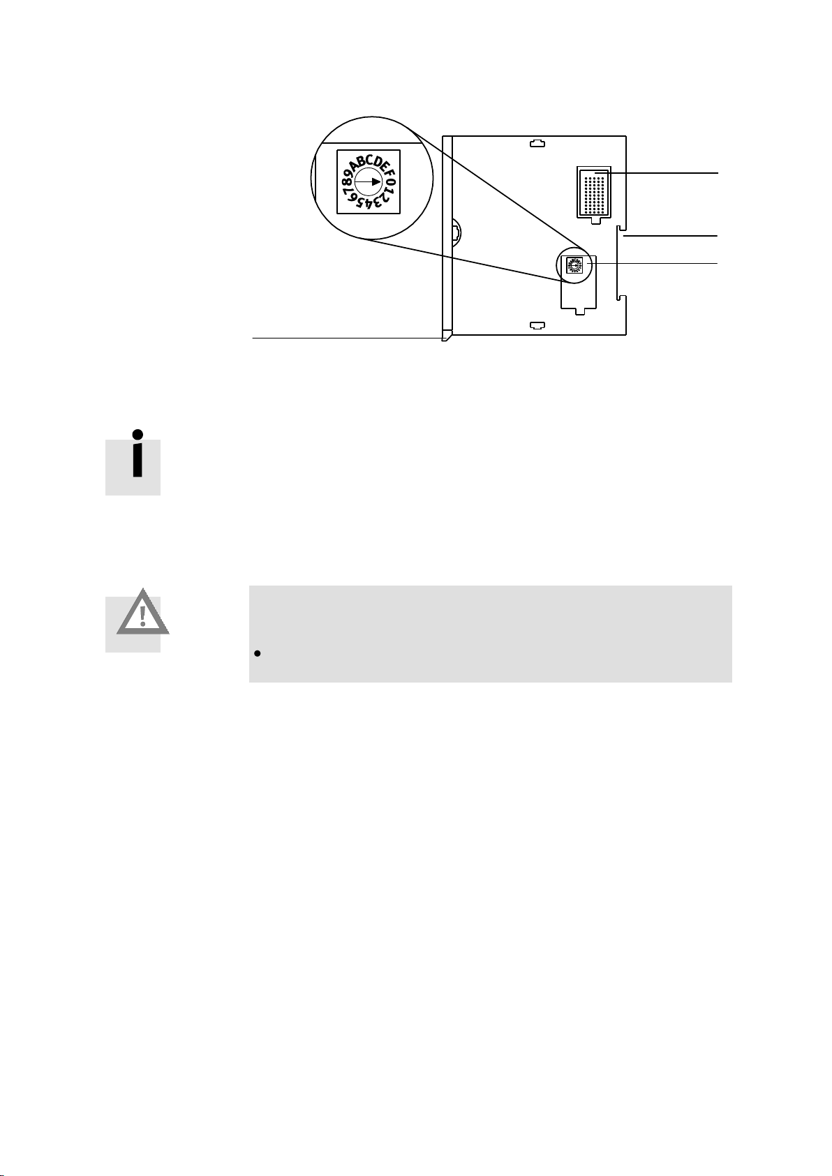
1 RS 485 A interface (X1)
2 Rotary switches
3 USB interface
(X8)
2 1 3
3.4.3 RS 485 A interface (reserved for expansion)
This interface is reserved for later expansions.
Fig. 3.6 Rotary switch on the central module (reserved for later expansions)
3.4.4 USB interface (for the service technician)
The CMXR modular control system includes one USB Master.
The USB connection (X8) is used solely for diagnostic purposes. Using the appropriate
software, diagnostic data (status reports) and program data generated by the device can
be copied onto a USB stick via the USB interface.
3.4.5 Rotary switch (reserved for expansion)
Two rotary switches are located on the top right side of the housing for the central module. These rotary switches are planned for later expansions (factory setting = 0).
3.4.6 CAN interface X6
For the servo controller connection, a 9-pin CAN connection is located on the central control module (Sub-D plug). This connection is used as an incoming and continuing field bus
cable.
44 Festo GDCP-CMXR-HW-EN en

3. Installation of the CMXR-C1 central control unit
Only use the appropriate sockets that guarantee a secure push-in
connection. Sockets from the Festo range are appropriate (see
Appendix A.2).
CAN (X6) connection
Pin
Signal
Meaning
5
1
9
6
1
2
3
4
5
6
7
8
9
Housing
n.c.
CAN–L
SGND
TERM1
TERM1
GND
CAN–H
TERM2
TERM2
(screening)
Not connected
CAN Bus Low
Signal ground
TERM1 *)
TERM1 *)
optional GND
CAN Bus High
TERM2 *)
TERM2 *)
*) Connection for activating the internal terminating resistor (refer to CAN bus terminal)
1 CAN connection
2 Jumper 1 (CAN+)
3 Jumper 2 (CAN-)
4 Integrated ter-
minating resistor
4
3
Table 3.9 Pin assignment for CAN connection (X6)
CAN bus terminal
Install a bus terminal at both ends of the field bus (first and last slave).
A terminating resistor for the bus terminal is integrated in the device. If you install the device onto the end of the field bus, you can activate the integrated terminating resistor by
connecting pins 4 and 5 (TERM1) and pins 8 and 9 (TERM2) (see the following picture).
Fig. 3.7 CAN interface with activated bus terminal
The two jumpers "Term1" and "Term2" are used to connect the terminating resistor (R) to
the CAN data cables.
The CAN connection must be made using a suitable cable.
Festo GDCP-CMXR-HW-EN 0805NH 45

We recommend a data cable as set out in ISO/DIS 11898 (CAN
standard).
RJ45 socket (X5)
Pin
Signal
Explanation
1
2
3
4
5
6
7
8
Metal covering
TD+
TD-
RD+
n.c.
n.c.
RD-
n.c.
n.c.
Screened
Transmitted data+
Transmitted data
Received data+
Not connected
Not connected
Received data
Not connected
Not connected
Screened
Instructions on wiring can be found in section 3.3.
3.4.7 CAN interface X4 (optional module CECX-F-CO)
CAN interface X6 (see section 3.4.6).
3.4.8 Ethernet interface X5 (optional module CECX-C-ET)
The central control unit is equipped at the factory with the CECX-C-ET optional module
as standard. This module provides an Ethernet connection for the Ethernet controller
built into the central control unit. An RJ-45 connection is available on the front panel for
connecting to an Ethernet network. This means the device can be integrated into both a
10 Mbit/s and a 100 Mbit/s Ethernet.
Table 3.10 Pin allocation for the Ethernet interface (X5)
3.4.9 Using Compact Flash memory cards
To operate the CMXR multi-axis control system, a Compact Flash memory card must be
inserted in the slot with the corresponding firmware and, if necessary, application. The
memory card is used for storing machine data (e.g. tool data and recipes), dependent on
the application used. The memory card can not be used as a removable medium, because
system programs are also stored on it. It is recommended that the Festo memory card,
CAMC-CMXR-C1-CF-256M, be used. The following memory cards are compatible:
46 Festo GDCP-CMXR-HW-EN en

3. Installation of the CMXR-C1 central control unit
Memory capacity
Type (manufactured by Toshiba)
Type (manufactured by Simple Tech)
128 MB
THNCF128MDGI
SLCF128JU
256 MB
THNCF256MDGI
SLCF256JU
512 MB
THNCF512MDGI
SLCF512JU
1 GB
THNCF1G02DGI
SLCF1GBJU
Caution
Memory cards can be damaged if handled incorrectly
Do not remove or insert the memory card during operation.
Do not switch off the device whilst it is writing onto the memory
card.
Do not insert the memory card with too much force into the slot.
Do not drop the memory and do not bend it.
Keep the memory card away from moisture, heat and direct
sunlight.
Keep the memory card away from electrostatic sources or mag-
netic fields.
Note
Only approved memory cards may be used.
Table 3.11 Compatible memory cards
Precautionary measures to be taken when handling memory cards
The memory card is designed in such a way that it can only be inserted into the device in
one direction. The card should simply slip with ease into the slot. The status LED next to
the ejection button lights up if the device has reading or writing access to the card.
Festo GDCP-CMXR-HW-EN 0805NH 47

1 Status LED for
the memory card
2 Memory card
2
1
Inserting the memory card
This is how you insert the memory card:
1. Switch off the supply voltage.
2. Using only slight pressure, carefully insert the memory card in the direction of the
arrow until it engages.
Fig. 3.8 Inserting the memory card
48 Festo GDCP-CMXR-HW-EN en

3. Installation of the CMXR-C1 central control unit
Additional instructions on handling the memory card can be found
in the system manual for the CMXR multi-axis control system.
1 Ejection button
2 Object for
pressing the
ejection button
2
1
Removing the memory card
1. Switch off the supply voltage.
2. Carefully press the ejection button using a suitable object (e.g. blunt pencil). The card
will then be ejected by a few millimetres.
3. Carefully pull the card out of the slot.
Fig. 3.9 Removing the memory card
Festo GDCP-CMXR-HW-EN 0805NH 49

Information on this can be found in the online help for the software
as well as in the associated system manual.
4. Instructions on commissioning
4.1 General instructions on commissioning
The CMXR multi-axis control system is configured and commissioned using the appropriate software.
The firmware and the respective applications are stored on a memory card, which must be
inserted in the slot of the central control unit.
4.2 Performance of the central control unit
4.2.1 Running up performance
The running up performance is divided into the following three main sections:
- Running up the boot block
- Running up the firmware
- Running up the application.
The running up progress is shown in the 7-segment display.
- Numbers > 0 signal the progress during the running up of the boot system and the con-
trol system firmware.
- Special characters and letters (e.g. L, II, ...) describe the running up of the application
or various operating states of the device.
- An error display will be activated if errors are detected during the running up. Errors
are displayed parallel to the states. Here, the status is initially displayed and then the
two- or three-digit error number (e.g. "-,0,-,E,1,0") alternately. Every character is displayed for one second.
50 Festo GDCP-CMXR-HW-EN en

4. Instructions on commissioning
7-segment display
Step
1
The power supply is present (Power on), the module's hardware is initialized.
2
The consistency of the boot block is tested.
3
Power on self-test, consistency of the boot block is tested.
4
The firmware is loaded from the memory card into the DRAM.
5
The firmware is started.
6
Running up of the boot block is completed. The operating system is initialized and started.
7
Various firmware components (services, I/O system, communication) are
started.
8
Autostart query: Factory setting = Autostart is switched on (if the
Autostart function was deactivated, then at this point a press of the key
(CTRL-key) is expected).
9
Running up of the firmware is completed. The CP module is now ready to
operate. If an application is already present on the memory card, then this
will now be loaded.
Display during the running up of the boot system and the firmware
Table 4.1 Display during the running up of the firmware
Festo GDCP-CMXR-HW-EN 0805NH 51

7-segment display
Step
9
The application is unloaded and the memory is enabled.
10
The application is loaded into the memory.
11
STOP: The application is loaded, but will not yet be processed.
12
The application is started.
13
The application is running.
More detailed information on the performance of the CMXR multiaxis control system can be found in the corresponding system
manual.
7-segment
display
Main operating states
Description
Init
In this operating status:
– the user application is unloaded and the memory enabled (CAUTION:
some configuration changes are only applied after Power on or Reset).
– the transmitting of process data is stopped.
– the visualisation is unloaded.
Stop
In this operating status:
– all global objects, system variables, motion modules etc. are created.
– the interpolator is stopped (no path data available).
– the exchange of process data is started, the output data are set to zero
(digital and analogue outputs: 0V, drives in the "Switch-on lock" status).
The inputs from other I/O modules are not applied.
Run
In this operating status:
– the application programs are processed, the process data is exchanged
according to the configuration.
– the process output data are updated (Unfreeze IO).
– the visualisation application is loaded.
Display during the running up of the application
After the firmware is booted, the system goes into the Init. state
Table 4.2 Display during the running up of the application
4.2.2 Operating states
The control system recognizes the following operating states:
Table 4.3 Operating states
52 Festo GDCP-CMXR-HW-EN en

4. Instructions on commissioning
Caution
Operational errors in conjunction with the CTRL key can cause system faults and lead to loss of data.
Only press the CTRL key upon being instructed to do so by Festo
service staff.
You can switch between the operating states by using the CTRL key.
4.2.3 Behaviour in the event of module errors
Should an error occur, then this will be displayed on the 7-segment display on the central
module. For more information, see section 5.3.1.
4.2.4 Behaviour in the event of power supply failure
A reset is triggered in the event that the complete supply fails. All modules connected in
series are also put into the Reset status and all outputs are reset.
The data in the battery-buffered SRAM are retained.
4.2.5 Control key (CTRL key)
The CTRL key is located next to the 7-segment display on the central modules. This key
can be used by the service technician, for example, to delete data from the memory card,
create Report files or delete Retain data.
Festo GDCP-CMXR-HW-EN 0805NH 53

Diagnostics
options
Brief description
On-the-spot diagnosis via LED
LEDs on the modules indicate signal states, hardware errors, bus errors etc. (see the
manual for the relevant module).
On-the-spot diagnosis via the
7-segment display
The 7-segment display indicates the corresponding error codes in the event of a fault
(see section 5.3.1). These errors can be acknowledged by pressing briefly on the CTRL
key on the central module.
Diagnosis via
software tools
Information on this can be found in the online help for your configuration software.
LED
Description
Power (green)
Lighting up green: power supply present.
Dark: no power supply.
LED
Description
RX (green)
Lights up briefly when a CAN message is received.
TX (yellow)
Lights up briefly when a CAN message is sent.
5. Diagnostics and error handling
5.1 Summary of diagnostic options
The CMXR multi-axis control system offers comprehensive options for diagnostics and
error handling. The following options are available:
Table 5.1 Diagnostics options
5.2 On-the-spot diagnosis via LED
5.2.1 Power LED
The green Power LED is located above the CTRL key on the central modules.
Table 5.2 Power LED
5.2.2 CAN status LEDs
The central control unit has the following two CAN status LEDs on the front panel.
Table 5.3 CAN status LEDs
5.2.3 Ethernet status LEDs
A Link status LED (green) and an Activity LED (yellow) are located on the Ethernet socket
(RJ-45). They light up when telegrams are sent or received.
54 Festo GDCP-CMXR-HW-EN en

5. Diagnostics and error handling
LED
Description
Link status (green)
Lights up as soon as an Ethernet connection is present.
Activity (yellow)
Lights up when data are sent and received.
LED
Description
Status LED (red)
Lights up red during write/read access to the memory card.
Is dark if there is no write/read access to the memory card.
Table 5.4 Ethernet status LEDs
5.2.4 Status LED for the memory card
A status LED is located next to the ejection key for the memory card. It lights up when the
system accesses the memory card.
Table 5.5 Status LED for the memory card
5.3 On-the-spot diagnosis via the 7-segment display
Errors can occur or be present in or during the transitions of the control system's respective operating states (e.g. STOP to RUN). These errors are indicated in the 7-segment display as a sequence of characters together with the current status. Every single character in
the sequence is shown one after the other at 1 second intervals.
The error display can be acknowledged by briefly pressing the CTRL key. After this, the
normal status is displayed.
Example: display during the running up of the firmware
The following sequence of characters signals error 51 in the "Load Firmware" status (no
firmware found):
Status Error
, , , , ,
Example: display during the running up of the application:
The following sequence of characters signals error 203 in the Init status (installation of the
application failed):
Status Error
, , , , , ,
Festo GDCP-CMXR-HW-EN 0805NH 55

Error displays not listed are intended for the support team at Festo.
Error status
Cause
Action
2 – E 401
Extended boot system was not found
Re-initialise the memory card with FCT
2 – E 402
CRC error in extended boot system
Re-initialise the memory card with FCT
2 – E 403
Boot system not suited for HW revision
Re-initialise the memory card with FCT
5.3.1 Error codes
Possible error codes are dependent on the current operating status of the device and
summarised accordingly in the following tables. This means that a first diagnosis is possible without reading out the status report files.
Running-up errors: Error during Power-on self-test
56 Festo GDCP-CMXR-HW-EN en

5. Diagnostics and error handling
Error status
Cause
Action
3 – E 501
Firmware package was not found
Re-initialise the memory card with FCT
3 – E 502
CRC error in firmware package
Re-initialise the memory card with FCT
3 – E 503
Firmware package not suited to HW
Re-initialise the memory card with FCT
3 – E 504
Not enough memory for the firmware
package
Re-initialise the memory card with FCT
Error status
Cause
Action
5 – E 101
Operating system error
Re-initialise the memory card with FCT
5 – E 205
Too many peripheral modules connected
in series
Reduce the number of modules connected
in series
More detailed information on handling the errors in your CMXR
multi-axis control system can be found in the system manual.
Running-up errors: Error loading the firmware
Running-up errors: Error when initialising and starting the operating system
Error handling
Festo GDCP-CMXR-HW-EN 0805NH 57

The device may only be opened by qualified specialists and maintenance work may only be carried out if expressly permitted by
Festo. Other manipulations on the device result in the guarantee
being invalidated.
Recommendation: Change the battery every 3 years.
The battery may only be replaced by a battery of the same type.
Only the following battery type is permissible:
- Battery type: CR2032 (Lithium-Mn, 3 V/220 mAh).
Caution
Short-circuits can cause flammable materials to ignite
Although batteries have a low voltage, they can give off enough
current in a short circuit to cause flammable materials to ignite.
Please note that the regulations for special waste must be ob-
served when disposing of the batteries.
6. Maintenance and care
6.1 Changing the battery
The central control unit is equipped with a real-time clock (RTC). When the power supply is
switched off, the real-time clock is boosted with a battery. The service life of the battery is
at least 3 years.
The battery is located on the right side of the housing, under the lower cover (see Fig. 6.1
Position of the battery).
58 Festo GDCP-CMXR-HW-EN en

6. Maintenance and care
Caution
Bent contact springs can lead to the battery short circuiting
Proceed carefully when changing the battery. Do not use exces-
sive force.
1 Position 1
(insert battery)
2 Position 2
(battery engages)
3 Battery (behind
the cover)
4 Right-hand side
of housing of central control unit
4 3 2
1
Changing the battery
This is how you change the battery:
1. Remove the lower cover on the right side of the housing.
2. Remove old battery by using an antistatic plastic tweezers. In doing so, place the
tweezers in the position marked by the arrow (see Fig. 6.1 Position of the battery).
3. Insert the new battery, as shown above, in position 1 and allow it to engage in posi-
tion 2. Please make sure here that the battery engages in the upper and lower holding
claw.
4. Close the battery cover.
Fig. 6.1 Position of the battery
6.2 Cleaning
Clean the device, if required, with a soft cloth.
Festo GDCP-CMXR-HW-EN 0805NH 59

60 Festo GDCP-CMXR-HW-EN en

A.1. Technical data
A. Technical appendix
Festo GDCP-CMXR-HW-EN 0805NH 61

General information
Short type code
CMXR-C1
Nominal operating voltage
[VDC]
24
Operating voltage range
[VDC]
19,2 ... 30
Total power consumption
[W]
25
Ambient temperature
[°C]
5 ... 55
Storage temperature
(without visualisation)
[°C]
–40 ... +70
Relative air humidity
(non-condensing)
[%]
10 ... 95
Protection class as per EN 60529
(plug connector inserted)
IP20 (as per EN 60529)
Protection against electric shock
(protection against direct and
indirect contact acc. to
IEC/DIN EN 60204-1)
by connection to a PELV power unit (Protected Extra Low
Voltage)
Electrical protection class
III
Insensitivity test against oscillation
as per IEC 60068-2-6-FC;
3.5 mm path at 5 ... 9 Hz,
1 g acceleration at 9 ... 150 Hz
Insensitivity test against shock
as per IEC 60068-2-27;
max. 15 g, 11 ms (half sine)
A.1 Technical data
A.1.1 General technical data
Table A.1 General technical data
62 Festo GDCP-CMXR-HW-EN en

A.1. Technical data
Type
CMXR-C1
Product weight
[g]
580
Control elements
CTRL key
Status displays
– 7-segment display
– Power LED (green)
CPU data
400MHz processor, 64 MB DRAM
Serial interface
– Connection technology
– Transmission rate
– Electrical isolation
[bit/s]
RS 485 (cannot be used currently)
Sub-D pin, 9-pin
1200 ... 115000, can be set via software
No
Fieldbus interface
– Connection technology
– Transmission rate
– Electrical isolation
[kbps]
CAN bus
– Sub-D pin, 9-pin
– 1000
– No
USB interface
USB 1.1 1)
Slots
1 slot for CAN optional module
1 slot for Ethernet interface
1 slot for memory card (Compact Flash type 1)
Ethernet
– Connector plug
– Data transmission speed
– Supported protocols
[Mbit/s]
RJ 45 (8-pin, socket)
10
TCP/IP; Modbus TCP ; Easy IP
Programming, working language
FCT (Festo Configuration Tool)
1) Only for service purposes
A.1.2 CMXR-C1, centralcontrol unit
Table A.2 Technical data CMXR central module
Festo GDCP-CMXR-HW-EN 0805NH 63

A.2 Accessories
Please select the appropriate accessories from our catalogue www.festo.com/catalogue .
64 Festo GDCP-CMXR-HW-EN en

A.3. Power consumption of components and modules
Caution
Operative malfunctions
Make sure that the power requirement of all the connected-in-
series and installed modules does not exceed the limit of 7 W in
total.
Module
Type
Power consumption [W]
(own requirement)
Optional modules
CECX-C-ET
0,5
CECX-F-CO
0,12
Peripheral modules
CECX-D-16E
0,4
CECX-D-14A-2
0,4
CECX-D-8E8A-NP-2
0,4
CECX-A-4E4A-V
0,7
CECX-A-4E4A-A
0,7
CECX-C-2G2
0,6
CECX-F-PB-S-V0
2
A.3 Power consumption of components and modules
For its own requirements, the central module needs 8 W. The central module provides 7 W
for supplying the peripheral and optional modules. You can calculate the total power consumption of all assembled modules by adding up the power consumption of all the single
modules.
The following table shows the power consumption of the modules:
Table 6.3 Power consumption of optional and peripheral modules
Calculation example: Power consumption of peripheral and optional modules
1 x CECX-C-ET: 0.5 W
1 x CECX-D-8E8A-NP-2: 0.4 W
2 x CECX-D-16E 0.8 W
Total: 1.7 W
The complete device (incl. central control unit) would have a power consumption of
8 W + 1.7 W = 9.7 W
Festo GDCP-CMXR-HW-EN 0805NH 65

From the very outset, please make sure the wiring and screening is
carried out with care, and in accordance with the guidelines described.
A.4 Instructions on EMC-compliant wiring
The resistance to interference of an electrical system depends significantly on EMCcompliant wiring and screening. Service practice shows that inadequate wiring and
screening of system components is frequently the cause of system faults and failures.
Basic structure of EMC measures
The EMC concept for the device is aimed at making sure that every module can individually resist the effects prevalent in an industrial environment where electromagnetic interference is present. This is based on the screen housing being closed. This screen housing
is suitably expanded by means of screened interfaces or, with unscreened interfaces, the
opened up screen housing is "closed" again by means of filters.
The relevant connections are provided on the modules for screened interfaces. It is, therefore, not necessary to connect these cable screens to the system via additional screening
clamps.
Unscreened interfaces are filtered at their connecting points in accordance with their required signal. It is, therefore, not necessary to additionally filter these wires.
Which EMC measures must be met?
EMC measures concentrate on the areas:
- Screening
- Potential equalisation between system components
Important here is the faultless execution, in practice, of the measures described in the
following sections. The most frequent causes of failure are poor contacts in earthing and
screening connections. This is why the following general points in particular need pointing
out.
Contacting of earthing and screening connections
- Low-impedance connection for the parts. This means highly conductive (for high fre-
quencies, too) and is achieved by: large surface area connections, short earthing wires
(where possible), use of wide earthing straps instead of wires, if possible.
- Planiform contact of bare metal is required.
- Contact surfaces must be protected against corrosion.
- Use toothed discs when connecting painted parts or parts with an unclean surface;
where possible, on all connecting points.
Just earthing an electrical system is an insufficient EMC measure and is mainly used for
protection against electric shock if conductive parts are touched.
66 Festo GDCP-CMXR-HW-EN en

A.4. Instructions on EMC-compliant wiring
Check list for EMC measures
Screened communication wires (CAN, Ethernet, USB, ... ):
- Is the screen connected flush with the metallic plug at both cable ends?
- Is the screen continuously present (beware of wall bushing)?
- Is the used communication partner suitable for an industrial interference environment?
Analogue cables
- Twisted pair cables used?
- Is cable screening connected to the 0 V terminal in the analogue module via cable, to
screen 50 Hz fields?
Fundamentally, for all of the device's interfaces, you do not have to observe any type of
special wiring.
Festo GDCP-CMXR-HW-EN 0805NH 67

B. Index
A
Air-conditioning and venting ................ 28
Areas of application and approval by
authorities .......................................... 6
B
Battery ................................................ 56
C
CAN bus terminal ................................. 43
CAN cable ............................................ 37
CAN status LED .................................... 52
Central module .................................... 16
Changing the battery ........................... 57
Compact Flash memory card ................ 44
CTRL key .............................................. 51
D
Diagnostics.......................................... 52
E
Earth terminal ...................................... 41
Earthing ............................................... 40
Electrical interface ............................... 17
Encoder interface................................. 19
Error codes .......................................... 54
Ethernet connection ............................ 44
F
Fieldbus interface ................................ 17
I
Input module ....................................... 17
Input/output module ........................... 18
Inserting the memory card ................... 46
Installation of an optional module ....... 22
Intended use ......................................... 5
M
Mounting ............................................ 28
Mounting clearances ........................... 27
Mounting dimensions ......................... 27
O
Operating states ................................. 50
Optional modules ................................ 17
Output module .................................... 18
P
Peripheral modules ............................. 17
Power consumption ............................ 60
Power LED ........................................... 52
R
Removing an optional module ............. 22
Removing the memory card ................. 47
Retain data ......................................... 13
Robot control ...................................... 14
Rotary switch ...................................... 42
Running up performance ..................... 48
S
Safety precautions ................................ 9
Segment display ................................. 53
Service ................................................ 11
Setting the module address ................ 23
Slot ............................................... 44, 48
Status report ....................................... 13
T
Target group ....................................... 11
U
USB connection ................................... 42
 Loading...