

Festo CMSX-...-C-U-F1 series, CMSX-P-S series, CMSX-P-SE series Operating Instructions Manual

Positioner
CMSX-...-C-U-F1-...
Festo AG & Co. KG
Ruiter Straße 82
73734 Esslingen
Germany
+49 711 347-0
www.festo.com
Operating instructions
(Translation of the original instructions)
8080775
2017-12b
[8062134]
Positioner CMSX English..............................................
For all available product documentation è www.festo.com/pk
1 Safety
1.1 Intended use
The positioner is intended for controlling the position of the following actuators in
process automation systems:
– pneumatic quarter turn actuators (single- or double-acting)
– pneumatic drives (double-acting) with connected external path/angle sensor
Quarter turn actuators with a mechanical interface in accordance with VDI/VDE
recommendation 3845 are suitable for operation of the positioner CMSX-P-S...
(rotary).
Mounting and commissioning is to be carried out only by qualified personnel,
in accordance with the documentation.
The product may only be used in its original status without unauthorized
modifications.
Only use the product if it is in perfect technical condition.
Observe the product labelling.
Use only compressed air in accordance with the specifications è Technical data.
The cable connector supplied only for cable throughfeed. To achieve the degree
of protection IP65, seal each cable entry tight (cable fitting, blanking plug).
Observe the handling specifications for electrostatically sensitive devices.
1.2 Return to Festo
Hazardous substances can endanger the health and safety of personnel and cause
damage to the environment. To prevent hazards, the product should only be re
turned upon explicit request by Festo.
Consult your regional Festo contact.
Complete the declaration of contamination and attach it to the outside of
the packaging.
Comply with all legal requirements for handling hazardous substances and
transporting dangerous goods.
2 Product overview
2.1 Function
The CMSX digital electropneumatic positioner enables simple and efficient posi
tion control based on the PID control algorithm. The position specification is
provided via an analogue setpoint signal. The current position of the actuator is
detected as follows:
– CMSX-P-S-... (rotary): through an integrated potentiometer
– CMSX-P-SE-... (linear): through an external path/angle sensor
The PID controller compares the measurement value with the analogue-specified
setpoint value and actuates the solenoid valves.
2.2 Configuration
CMSX-P-S-... (rotary)
3
45
7
8
6
6
12 3
9aJaAaB
1 Housing cover
2 Inspection window for LCD display
3 Housing screws
4 Blanking plug
5 Cable entry with cable fitting for
electrical connecting cable
6 Mounting thread for mounting
bridge
7 Shaft
8 Mechanical coupling
9 Base plate
aJ Housing
aA Pneumatic connections (G1/8)
aB Earth terminal
Fig. 1
CMSX-P-SE-...(linear)
6
12 3 4 5
789
6
3
aJ
1 Housing cover
2 Inspection window for LCD display
3 Housing screws
4 Cable entry with cable fitting for
external path/angle sensor
5 Cable entry with cable fitting
for electrical connecting cable
6 Mounting thread
7 Base plate
8 Housing
9 Pneumatic connections (G1/8)
aJ Earth terminal
Fig. 2

Operating elements and connections in the device – example: CMSXPSE...
(linear)
12
4567
8
3
1 LCD display
2 Terminal strip 1 (pin 1 … 14)
3 Terminal strip 2 (pin 1 … 3)
4 Terminal strip 3 (pin 15, 16)
5 Pushbutton Set
6 Pushbutton Sub
7 Pushbutton Add
8 Earth terminal
Fig. 3
2.3 Product variants and type code
Feature Value Description
Type CMSX Positioner for process automation
Product version P Primarily polymers
Design S Positioner, displacement/angle measurement
integrated
SE Positioner, displacement/angle measurement
external
Display type C LCD, backlit
Setpoint value U Configurable (0…10 V, 0…20 mA, 4…20 mA)
Position feedback F1 4…20 mA
Function D Double-acting
S Single-acting
Standard nominal flow rate 50 50 l/min
130 130 l/min
Safety function A Open or close in case of breakdown
1)
C Block in case of breakdown
1)
Generation G1 First generation
Second generation
1) Failure of the operating voltage supply or the setpoint specification
Fig. 4
3 Further information
– Accessories è www.festo.com/catalogue.
– Documents and literature è www.festo.com/sp.
4 Service
Contact your regional Festo contact person if you have technical questions
è www.festo.com.
5 Transport and storage
– Store the product in a cool, dry, UV-protected and corrosion-protected environ
ment. Ensure that storage times are kept to a minimum.
6 Mounting
Note
Mounting only by qualified personnel.
Note
Protect the underside of the device against splash water, moisture and humidity
by selecting an appropriate mounting position.
Pay attention to the actuator's direction of motion.
Use only mounting bridges DARQ-K-P-A1-F05-... or DADG-AK-F6-A2
è www.festo.com/sp.
6.1 CMSX-P-S-... (rotary)
4
7
6
3
2
1
5
Fig. 5
1. Determine the direction of rotation of the quarter turn actuator.
2. Close the process valve.
3. Switch off compressed air and power supply.
4. Fasten the mounting bridge 2 to the positioner:
– 4housing screws M44
– Tightening torque 1.5 Nm ±20 %
5. Fasten the mechanical coupling 5 to the shaft of the positioner 1:
– 2 threaded pins 6
– Tightening torque 0.5 Nm ±10 %
6. Place the positioner with the mounting bridge and the coupling on the quarter
turn actuator 7 and align it. The angle of rotation of the actuator must be within
the sensing range of the positioner è Fig. 6.
7. Secure the positioner with mounting bridge to the quarter turn actuator:
– 4mounting screws M53
– Tightening torque 3 Nm ±20 %
3
21
2
1 Flat spot of the shaft
2 Identification of the alignment
of the flat spot
3 Identification for sensing range
Fig. 6
The angle position of the quarter turn actuator is detected by the shaft of
the positioner.
The shaft of the positioner can be freely rotated and does not have a mechanical
stop. The permissible sensing range is 100°.

6.2 CMSX-P-SE-...(linear)
5
4
2
1
6
3
Fig. 7
1. Close the process valve.
2. Switch off compressed air and power supply.
3. Fasten the mounting bridge 1 to the positioner:
– 4 housing screws M4 3
– Tightening torque 1.5 Nm ±20 %
4. Secure the housing (flange socket) 5 to the linear actuator 6:
– 4 mounting screws M54
– Tightening torque 2.7 Nm±10 %
5. Secure the positioner with mounting bridge to the housing (flange socket):
– 4 mounting screws M62
– Tightening torque 3 Nm ±20 %
7 Installation
7.1 Pneumatic
1
2
65
34
1 Supply port (1)
2 Working port (2)
3 Working port (4)
4 QS-1/8-…-I-push-in fitting
(accessories)
5 Silencer (accessory)
6 Exhaust port (3)
Fig. 8
Recommendation: Use push-in fittings of type QS-1/8-…-I and tubes of type PUN.
1. Switch off compressed air and power supply.
2. Connect working port (2) and working port (4) to the working ports of the
pneumatic actuator.
In the case of single-acting actuators, only connect working port (4). Seal
working port (2) with a blanking plug.
– Keep the tubing short.
3. Connect the supply port (1) to the compressed air source.
4. Screw a suitable silencer into the exhaust port (3).
7.2 Electrical
Warning
Electrical voltage.
Injury due to electric shock.
Switch off power supply before opening the device.
Note
The IP65 degree of protection depends on the type of electrical connection.
Inappropriate cables or an incorrect installation will reduce the degree of protec
tion of the positioner.
1. Switch off compressed air and power supply.
2. Loosen the housing screws è Fig. 1,3. Remove the cover of the housing.
3. Guide the electric connecting cable through the cable fitting to the terminal
strips è Fig. 1,5:
– Max. length of the signal line 30 m
– Outside diameter of electric connecting cable: 7…13 mm
– Conductor cross-section: max. 1.5 mm²
– Use wire end sleeves.
4. If different reference potentials are used for the input signals and the operating
voltage supply, stabilise input signals:
– Current input signal: Set wire bridges between pin 4 and pin 6.
– Voltage input signal: Set wire bridges between pin 2 and pin 6.
5. For CMSX-SE-... (linear): Guide the connecting cable for external path/angle
sensor through the cable fitting (è Fig. 2,4) to the terminal strip 2.
– Max. length of the signal line 15 m
– Outside diameter of electric connecting cable: 3…6.5 mm
– Conductor cross-section: max. 1.5 mm²
– Do not use any wire end sleeves.
6. Wire the electrical connections è Fig. 9.
– Tightening torque: max. 0.6 Nm
7. Connect the earth terminal with low impedance (short cable with large cross
section) to the earth potential è Fig. 3, 8. Leave the cable at pin 9 unchanged.
8. Tighten the union nut of the cable fitting è Fig. 2,4,5.
– Tightening torque: 1.5Nm
9. If commissioning is carried out immediately after installation, leave the cover
dismounted.
10.Place the housing cover in position and tighten the 4 housing screws
è Fig. 2, 3.
– Observe the correct position of the seals.
– Tightening torque: 1.5Nm
Pin allocation
Pin Designation Description
Terminal strip 1 (pin1…14)
1 Usp+ Voltage input signal + Setpoint input 0…10 V
2 Usp- Voltage input signal -
3 Isp+ Current input signal + Setpoint input
4…20 mA, 0…20 mA
4 Isp- Current input signal 5 +24 VDC Operating voltage supply; 24 VDC Supply to electronics and
valves
6 0 VDC Operating voltage supply; 0 VDC
7 I- Current output signal - Actual value output
4…20 mA
8 I+ Current output signal +
9 – Connected to the ear th terminal
at the factory
Leave the cable unchanged
10 ALARM Alarm digital output Alarm output
11 D-OUT1 Digital output Out 1 Status output
12 D-OUT2 Digital output Out 2
13 +24 VDC Load voltage supply for outputs; 24 V DC Supply to digital outputs
14 0 VDC Load voltage supply for outputs; 0 V DC
Terminal strip 2 (pin1…3)
1 0 VDC Operating voltage-
External path/angle sensor
External potentiometer
path/angle sensor with
max. 20 kΩ
2 U+ Sensor signal actual value
3 +5 VDC Operating voltage+
External path/angle sensor
Terminal strip 3 (pin 15, 16)
15 D-IN- Digital input - Digital input
1)
16 D-IN+ Digital input +
1) Permits separate circuits if separate power supply units are used
Fig. 9
Setpoint inputs è Pin1…4
The setpoint value can be specified as an external voltage or current signal.
With the SIGNAL parameter, the type of setpoint value can be selected è Fig. 14.
Actual position output è Pin 7, 8
The actual position (valve position VP) is output as a current signal and can be
processed in higher-level systems. The OPEN parameter influences the actual
position è Fig. 14.
Digital output ALARM è Pin10 and pin14
The ALARM digital output delivers high level if the maximum positioning time
is exceeded.
The maximum positioning time is determined during initialisation.
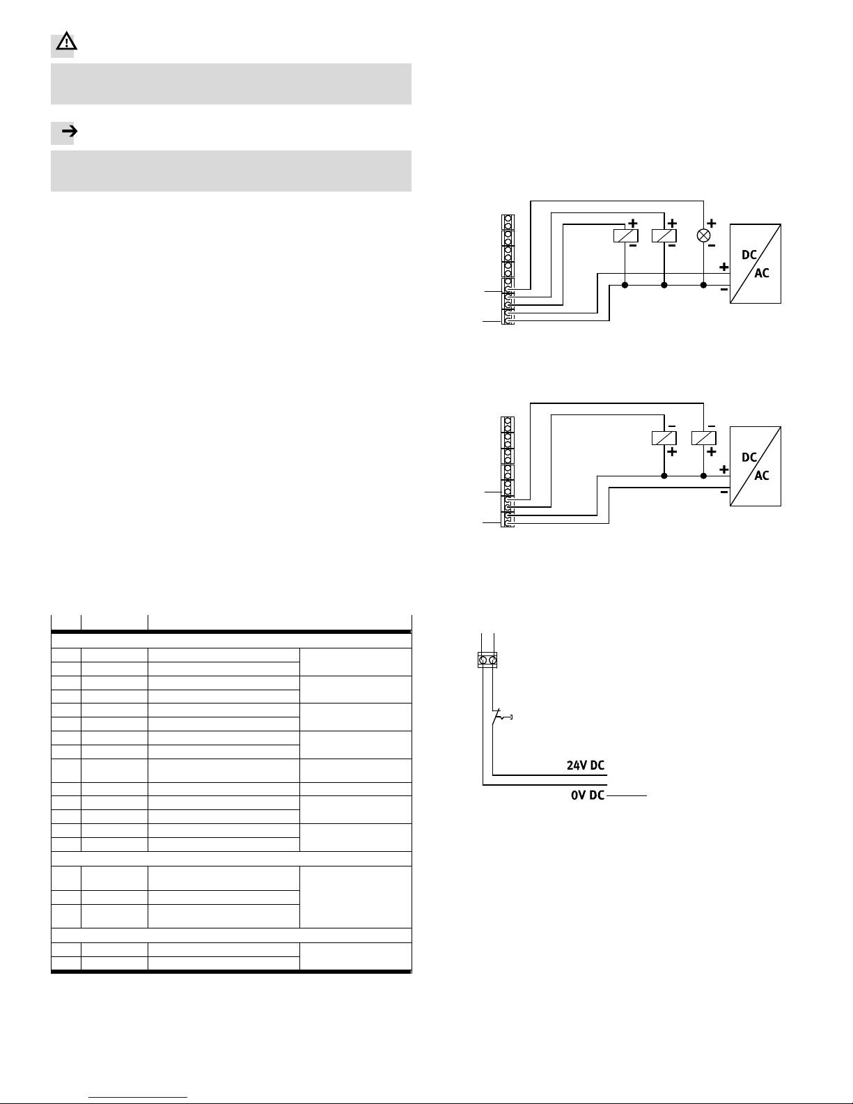
Digital outputs D-OUT1 and D-OUT2 è Pin11,12 and pin14
The digital outputs D-OUT1 and D-OUT2 can be connected as PNP or NPN outputs.
10
14
Fig. 10
To connect the digital outputs ALARM, D-OUT1 and D-OUT2 as PNP outputs, con
nect the minus pole of the load to pin 14. The PNP outputs are positive switching,
from plus to minus.
10
14
Fig. 11
To connect the digital outputs D-OUT1 and D-OUT2 as NPN outputs, connect
the plus pole of the load to pin 13. The NPN outputs are negative switching,
from minus to plus.
Digital input è Pin15,16
15 16
1
1 Reference potential
Fig. 12

8 Commissioning
Note
Commissioning should only be carried out by qualified personnel.
For detailed instructions on commissioning è www.festo.com/sp.
Prerequisites
The positioner is fully mounted and connected.
Familiarize yourself with the menu system, the functions of the pushbuttons and
the parameters of the positioner prior to commissioning.
Checking operating conditions
Check operating conditions and limit values è Technical data.
Check the connection points for tightness.
Ensure there is a stable operating voltage supply, particularly during the com
missioning phase.
Factory settings
Menu Display Description
Basic menu level
- OPERAT Auto
Automatic
ACTUAT Stopped
PID controller not active
Main menu
2 CONFIG SIGNAL 4-20mA
Current input active; 4 … 20 mA
OPEN
1)
anti-clk
Active direction of the actuator clockwise
DIRECT increase
The setpoint position is increased with a rising
setpoint value
CHARACTE linear
Linear setpoint characteristic curve
D-OUT1
D-OUT2
power-L
power-L
Low level if load voltage supply is present
for outputs
D-IN stop-H
In the case of high level, block the actuator
in position
3 PARA DEADBAND 1.0%
Deadband of the PID controller: 1.0 %
PID--P 1
P-propor tion of the PID controller: 1
PID--D 4
D-propor tion of the PID controller: 4
MIN 0%
Value for the lower stroke limit: 0 %
MAX 100%
Value for the upper stroke limit: 100 %
SPMIN 0%
Value for the lower setpoint limit or seal-closing
boundary: 0 %
SPMAX 100%
Value for the upper setpoint limit or
seal-closing boundary: 100 %
4 CURVE 0% 0.0
Support point at 0 % setpoint signal: 0 %
5% 5.0
Support point at 5 % setpoint signal: 5 %
... ...
...
100% 100
Support point at 100 % setpoint signal: 100 %
1) Only CMSX-P-S-... (rotary)
Fig. 13
8.1 Switch on positioner
1. Switch on the operating voltage supply.
2. Switch on the setpoint specification.
3. Switch on the compressed air.
è When the operating voltage supply is switched on for the first time, the fact
ory settings are effective. The positioner behaves as follows:
– Positioner is in the automatic mode
– PID controller is not active and does not react to setpoint specifications.
If the operating voltage supply is switched back on, the last operating
status is immediately effective. If the PID controller is activated, the current
setpoint value is immediately valid.
è The initial position is displayed (example).
--- 0.0%
VP: 0.0%
8.2 Initialisation
The following values are determined during initialisation:
– Permitted stroke range
– Maximum positioning time
During initialisation, movement takes place into both end positions in succession,
independently of the present setpoint value.
Perform initialisation in the following cases:
– During commissioning
– After changes in the system structure
Initialisation can be carried out manually or automatically (recommendation:
Automatically).
Menu 2 CONFIG
Display Description
MENU 2 CONFIG
SIGNAL
Signal type
0-10V Voltage input (pin 1, 2); 0 … 10 V
4-20mA
Current input (pin3,4); 4 … 20 mA (presetting)
0-20mA
Current input (pin 3, 4); 0 … 20 mA
OPEN
Active direction of the actuator - only CMSX-P-S-...(rotary)
clockwis
Clockwise
anti-clk
Anti-clockwise (presetting)
DIRECT
Direction of action of the setpoint value signal
increase
The setpoint position is increased with a rising setpoint value
(presetting)
decrease
The setpoint position is increased with a falling setpoint value
CHARACTE
Type of setpoint characteristic curve
linear
Linear setpoint characteristic curve (presetting)
1:25
Equal-percentage setpoint characteristic curve
1:33
1:50
user-def
User-defined setpoint characteristic curve
D-OUT1
D-OUT2
Function of the digital outputs D-OUT1, D-OUT2
power-H
High level if load voltage supply is present for outputs
power-L
Low level, if load voltage supply is present for outputs (preset)
limit1-H
High level, if end position 1 is reached
limit1-L
Low level, if end position 1 is reached
limit2-H
High level, if end position 2 is reached
limit2-L
Low level, if end position 2 is reached
limits-H
High level, if end position 1 or end position 2 is reached
limits-L
Low level, if end position 1 or end position 2 is reached
stop-H
High level in the operating status, PID controller not active
stop-L
Low level in the operating status, PID controller not active
D-IN
Function of the digital input
(PID controller not active)
stop-H
In the case of high level, block actuator (presetting)
stop-L
In the case of low level, block actuator in position
lmt1-H
In the case of high level, travel to stop 1
lmt1-L
In the case of low level, travel to stop 1
lmt2-H
In the case of high level, travel to stop 2
lmt2-L
In the case of low level, travel to stop 2
Fig. 14

8.3 Menu structure
3
3
333
SIGNAL
0-10V
SIGNAL
4-20 mA
SIGNAL
0-20 mA
*CONFIG*
signal
33
OPEN
anti-clk
OPEN
clockwis
*CONFIG*
open
33
DIRECT
increase
DIRECT
decrease
*CONFIG*
direct
3
D-OUT1
power-H
D-OUT1
power-L
D-OUT1
stop-L
D-OUT1
stop-H
D-OUT1
limits-L
D-OUT1
limits-H
D-OUT1
limit2-L
D-OUT1
limit2-H
D-OUT1
limit1-L
D-OUT1
limit1-H
*CONFIG*
d-out1
33
D-IN
stop-H
D-IN
stop-L
D-IN
lmt2-L
D-IN
lmt2-H
D-IN
lmt1-L
D-IN
lmt1-H
*CONFIG*
d-in
33
CHARACTE
linear
CHARACTE
1:25
CHARACTE
user-def
CHARACTE
1:50
CHARACTE
1:33
*CONFIG*
characte
33
D-OUT2
power-H
D-OUT2
power-L
D-OUT2
stop-L
D-OUT2
stop-H
D-OUT2
limits-H
D-OUT2
limits-H
D-OUT2
limit2-L
D-OUT2
limit2-H
D-OUT2
limit1-L
D-OUT2
limit1-H
*CONFIG*
D-OUT2
33
--MENU-2 CONFIG
--MENU-3 PARA
--MENU-4 CURVE
--MENU-5 INFORM
--MENU-6 INIT
36
SP:50.0%
VP:50.1%
--> 50.0%
VP:50.1%
--- 50.0%
VP:50.1%
***50.0%
VP:50.1%
•ACTUAT•
Stopped
•ACTUAT•
Running
•OPERAT•
Manual
•OPERAT•
Auto
1/2
1: +
2: 4: ++
5: --
1/2
*SENSOR*
-----+--
*SENSOR*
------+-
*SENSOR*
----+---
*SENSOR*
+-------
*SENSOR*
-+------
NEEDSTOP
FIRST!
*SENSOR*
--+-----
*SENSOR*
---+----
*SENSOR*
ERROR
*SENSOR*
-------+
--MENU-1 SENSOR
1/2 1/2 1/2
3
1/2 1/2 1/2
66
1/2 1/2 1/2
1/2
1/2
1/2
1/2
1/2
1/2
1/2
1/2
1/2 1/2
1/2
1
2
4
OPEN
anti-clk
OPEN
clockwis
*CONFIG*
open
33
3
1 Basic menu level
2 Main menu level
3 1 = Press Add
2 = Press Sub
3 = Press Set
4 = Press and hold Add for 3seconds
5 = Press and hold Sub for 3seconds
6 = Press and hold Set for 3seconds
7 = Press and hold Add and Set for 3seconds
4 Submenu only available for CMSX-P-S-... (rotary)
Fig. 15

DEADBAND
1.0%
*PARA*
deadband
33
PID--P
1
*PARA*
pid--p
33
PID--D
4
*PARA*
pid--d
3
MAX
100%
*PARA*
max
33
SPMAX
100%
*PARA*
spmax
33
MIN
0%
*PARA*
min
33
SPMIN
0%
*PARA*
spmin
33
--MENU-3 PARA
36
1/2 1/2 1/2
3
1/2 1/2 1/2
1/2
1/2 1/2 1/2 1/2 1/2 1/2 1/2
*CURDEF*
0%
3
*CURDEF*
5%
*CURDEF*
10%
*CURDEF*
90%
*CURDEF*
100%
*CURDEF*
95%
--MENU-4 CURVE
36
3
3
3
3 3
1/2
1/2
1/2
1/2
1/21/2
*INFORM*
L1 0°
*INFORM*
L2 90°
*INFORM*
V1 ...k
*INFORM*
Ver ....
*INFORM*
V2 ...k
--MENU-5 INFORM
33
1/2 1/2 1/2 1/2
1/2
AutoInit
24-1
*INITIA*
Autoinit
3
7
Fcty Rst
ok
*INITIA*
Fcty Rst
37
--MENU-6 INIT
36
1/2
1/2
1/2
Sytm Rst
ok
*INITIA*
Sytm Rst
37
SetAsDef
Saved
*INITIA*
SetAsDef
37
1/2
1/2
AutoInit
24-2
AutoInit
24-n
AutoInit
OK
*SENSOR*
ERROR
AutoInit
failed
3
UserInit
11-0
*INITIA*
Userinit
3
7
UserInit
11-1
UserInit
11-n
UserInit
ok
*SENSOR*
ERROR
UserInit
failed
3
1
*INFORM*
L1 IN
*INFORM*
L2 OUT
1/2
3
2
1 Main menu level
2 1 = Press Add
2 = Press Sub
3 = Press Set
4 = Press and hold Add for 3seconds
5 = Press and hold Sub for 3seconds
6 = Press and hold Set for 3seconds
7 = Press and hold Add and Set for 3seconds
3 Submenu only available for CMSX-P-SE-... (linear)
Fig. 16

9 Operation
Observe the operating conditions.
Observe limit values.
After the supply voltage is switched on, the positioner is in the same operating
status and the same operating mode as was valid before the supply voltage was
switched off.
10 Maintenance
With intended use, the product is maintenance-free.
Clean the outside of the product with a soft cloth and soap suds.
11 Fault clearance
Note
For detailed instructions on fault clearance è www.festo.com/sp.
12 Dismantling
Note
Dismounting only by qualified personnel.
Caution
Despite switched-off compressed air, the working ports of the positioner remain
under pressure.
Exhaust working ports before removal of the tubing lines.
12.1 CMSX-P-S-... (rotary)
1. Switch off compressed air.
2. Activate the manual setpoint position mode in the basic menu level
(OPERAT Manual).
3. Move actuator until the working ports are completely exhausted.
4. Switch off power supply.
5. Loosen the housing screws è Fig. 1,3. Remove the cover of the housing.
6. Disconnect electrical and pneumatic connection.
7. Loosen 4 mounting screws (è Fig. 5, 3 ) from the actuator and remove
the positioner with mounting bridge.
12.2 CMSX-P-SE-... (linear)
1. Switch off compressed air.
2. Activate the manual setpoint position mode in the basic menu level
(OPERAT Manual).
3. Move actuator until the working ports are completely exhausted.
4. Switch off power supply.
5. Loosen the housing screws è Fig. 2,3. Remove the cover of the housing.
6. Disconnect electrical and pneumatic connection.
7. Loosen 4 mounting screws (è Fig. 7,2 ) from the housing (flange socket)
and remove the positioner with mounting bridge.
13 Disposal
Observe the local regulations for environmentally friendly disposal.
Dispose of the product in an environmentally friendly manner.
14 Technical data
CMSX-P-...-C-U-F1-...
Sensing range [°] 0…100
Conforms to standard VDI/VDE3845 (NAMUR)
Protection against short circuit Yes
Measured variable
– CMSX-P-S Rotation angle
– CMSX-P-SE Rotation angle or stroke through external
path/angle sensor
Reverse polarity protection – For setpoint value
– For operating voltage connection
Display type Backlit LCD
Setting options Via display and keys
Type of setpoint value characteristic curves – Linear
– Equal percentage (1:25, 1:33, 1:50)
– Freely adjustable over 21 support points
Leakproof characteristics Adjustable via SPMIN and SPMAX
Control range adaptation Adjustable
Alarm for exceeding limit value None
Active direction Adjustable, rising/falling
Operating pressure [bar] 3…8
Setpoint value [mA] 4…20; 0…20
[V] 0…10
Pneumatic initial position in case of breakdown
– CSMX-...-A Regulating effect opening/closing, adjustable
through pneumatic tubing connection
– CMSX-...-C Regulating effect blocking
Operating voltage range DC [V] 21.6…26.4
Max. load resistance of current output [Ω] 500
Idle current
– CSMX-...-G1 [mA] 100…300
– CSMX-... (2. generation) [mA] 90…300
Max. current consumption [A] 1
Max. output current [mA] 500
Switching level [V] Signal 0: 5; signal 1: 10
Max. current consumption
of the digital inputs at 24 V
[mA] 6
Deadband size
– CSMX-...-G1 [%] 0.1…10
– CSMX-... (2. generation) [%] 0.5…10
Operating medium Compressed air according to ISO8573-1:2010
[7:4:4]
Note on the operating medium Lubricated operation not possible
CE marking,
(Declaration of conformity
è www.festo.com/sp)
In accordance with EU EMC Directive
Protection class - in mounted state I P65
Ambient temperature [°C] -5…60
Storage temperature [°C] -20…60
UV resistance Ye s
Vibration resistance according to DIN/IEC 60068,
part 2-6
0.15 mm path at 10 … 58Hz1);
2 g acceleration at 58…150Hz
1)
Shock resistance according to
DIN/IEC60068par t 2‐29
±15 g with 11 ms duration; 5 shocks per
direction
1)
Cable connector – M20 for device connection
– M12 for connection of external path/angle
sensor – only CMSX-P-SE-... (linear)
Type of mounting With accessories, on flange according
to ISO 5211
Max. product weight [g] 970
Pneumatic port G1/8
Standard nominal flow rate
– CMSX-...-50 [l/min.] 50
– CMSX-...-130 [l/min.] 130
Materials
– Housing PC
– Threaded coupling (coupling) High-alloy stainless steel
– Seals NBR
– Adapter plate Aluminium,
– Plate (back plate) Aluminium,
– Cable connection PA
1) Only in combination with a mounting bridge as indicated in the accessories è www.festo.com/catalogue.
Fig. 17
 Loading...