

Page 1
Motor controller
CMMO-ST
Description
Motor controller
CMMO-ST-C5-1-DIO
8022056
1301a
Page 2
CMMO-ST
Translation of the original instructions
GDCP-CMMO-ST-EA-SY-EN
Adobe Reader
®
,CANopen®,CiA®are registered trademarks of the respective trademark owners in
certain countries.
Identificationof hazards and instructions on how to prevent them:
War n ing
Hazards that can cause death or serious injuries.
Caution
Hazards that can cause minor injuries or serious material damage.
Other symbols:
Note
Material damage or loss of function.
Recommendations, tips, references to other documentation.
Essential or useful accessories.
Information on environmentally sound usage.
Text designations:
• Activities that may be carried out in any order.
1. Activities that should be carried out in the order stated.
– General lists.
2 Festo – GDCP-CMMO-ST-EA-SY-EN – 1301a –
Page 3

CMMO-ST
Table of Contents – CMMO-ST
1 Safety and requirements for product use 9......................................
1.1 Safety 9..................................................................
1.1.1 General safety instructions 9.........................................
1.1.2 Intended use 10.....................................................
1.2 Requirements for product use 11...............................................
1.2.1 Technical requirements 11............................................
1.2.2 Qualification of the specialists (requirements for the personnel) 11............
1.2.3 Range of application and certifications 12................................
2Overview 13................................................................
2.1 System overview 13..........................................................
2.2 Overview of CMMO-ST 14.....................................................
2.2.1 General properties 14................................................
2.2.2 Commissioning options 14............................................
2.2.3 Control profiles of the I/O interface 14...................................
2.2.4 Closed loop versus open-loop operation 15...............................
2.3 Overview of CMMO-ST operating modes 15.......................................
2.3.1 Positioning mode 15.................................................
2.3.2 Speed mode 15.....................................................
2.3.3 Force mode 15......................................................
2.4 Overview of drive functions 16.................................................
2.4.1 Jogging 16.........................................................
2.4.2 Teac h 16..........................................................
2.4.3 Standstill monitoring 16..............................................
2.4.4 Brake 16..........................................................
2.4.5 Comparators & messages 17..........................................
2.4.6 Record Linking 17...................................................
2.4.7 Record switching by PLC 17............................................
2.4.8 Trace 17...........................................................
2.4.9 Firmware update 17.................................................
2.4.10 Parameter file 17....................................................
2.4.11 Flash memory 18....................................................
2.4.12 Higher-order control 18...............................................
Festo – GDCP-CMMO-ST-EA-SY-EN – 1301a – English 3
Page 4

CMMO-ST
2.5 Interfaces and simultaneous connections 18......................................
2.5.1 Number of connections 19............................................
2.6 Measuring reference system 19.................................................
2.6.1 Basic concepts 19...................................................
2.6.2 Calculationrules 20..................................................
2.6.3 Prefix and direction of rotation 21......................................
2.6.4 Units of measurement 21.............................................
2.7 Homing run 21..............................................................
2.7.1 Homing overview 21.................................................
2.7.2 Homing methods to a fixed stop 22.....................................
2.7.3 Homing methods to switch with/without index search 23....................
2.7.4 Homing method “current position” 24...................................
2.7.5 Automatic homing ( valve profile) 24.....................................
2.7.6 Movement to zero 25.................................................
2.8 Monitoring functions 25.......................................................
2.9 Safety aspects 26............................................................
3Mounting 27...............................................................
3.1 General instructions 27.......................................................
3.2 Dimensions of the controller 28.................................................
3.3 Mountingthe controller 29....................................................
3.3.1 Fitting 29..........................................................
3.3.2 H-rail mounting 30...................................................
4 Electrical installation 31......................................................
4.1 Overview 31................................................................
4.2 Power supply [X9] 33.........................................................
4.3 Functional earth 34..........................................................
4.4 I/O interface [X1] 35..........................................................
4.4.1 Electrical specifications of [X1] 36......................................
4.5 Reference switch [X1A] 36.....................................................
4.6 STO [X3] 37.................................................................
4.7 Encoder [X2] 38.............................................................
4.8 Motor [X6] 38...............................................................
4 Festo – GDCP-CMMO-ST-EA-SY-EN – 1301a – English
Page 5

CMMO-ST
5 Commissioning 39...........................................................
5.1 Safety regulations 39.........................................................
5.2 Ethernet interface (RJ-45) 41...................................................
5.2.1 Deliverystatus of the CMMO-ST 41.....................................
5.2.2 DHCP or fixed IP address 41...........................................
5.2.3 Safety in the network 42..............................................
5.2.4 Timeout 42........................................................
5.2.5 Initial start-up via Ethernet 43.........................................
5.3 Commissioning via web server 44...............................................
5.3.1 What does the web server enable? 44...................................
5.3.2 Parameter files 44...................................................
5.3.3 Initial start-up with the web server 46...................................
5.3.4 Creating a parameter backup file 50.....................................
5.4 Commissioning with FCT (Festo Configuration T ool) 51..............................
5.4.1 Installing the FCT 51.................................................
5.4.2 Starting the FCT 52..................................................
5.5 I/O interface 54.............................................................
5.5.1 Profiles for selection 54..............................................
5.5.2 Properties of the valve profile (7) 55....................................
5.5.3 Properties of the binary profile (31) 66..................................
5.6 Structure of the records in the record table 77.....................................
5.6.1 Positioning mode 77.................................................
5.6.2 Speed mode (binary profile only) 79.....................................
5.6.3 Force mode (only in binary profile) 80...................................
5.7 Record switching by PLC (binary profile) 81.......................................
5.8 Record linking (binary profile only) 82............................................
5.9 Comparators 83.............................................................
5.9.1 Position comparators 83..............................................
5.9.2 Speed comparators 84...............................................
5.9.3 Force comparators 84................................................
5.9.4 Time comparators 85................................................
5.10 Instructions on operation 86...................................................
Festo – GDCP-CMMO-ST-EA-SY-EN – 1301a – English 5
Page 6

CMMO-ST
6Diagnostics 87..............................................................
6.1 Types of malfunction 87.......................................................
6.2 7-segment display 87.........................................................
6.3 Diagnostic memory 89........................................................
6.4 Malfunctions: Causes and remedy 90............................................
6.4.1 Error responses 90..................................................
6.4.2 Table of error messages 90............................................
6.4.3 Problems with the Ethernet connection 103................................
6.4.4 Other problems and remedies 105.......................................
6.4.5 Malfunction“Index pulse too close on proximitysensor” (2Eh) 106.............
A Technical appendix 107........................................................
A.1 Technical data 107............................................................
B Control via Ethernet (CVE) 109..................................................
B.1 Basic principles 109...........................................................
B.1.1 Communication principle 109...........................................
B.1.2 CVEprotocol 110.....................................................
B.1.3 Controlling the drive 116...............................................
B.2 Explanation of increments 124..................................................
B.3 List of CVE objects 125.........................................................
C Glossary 132................................................................
6 Festo – GDCP-CMMO-ST-EA-SY-EN – 1301a – English
Page 7

CMMO-ST
Instructions on this documentation
This documentation is intended to help you safely work with the motor controller CMMO-ST.
Product identification, versions
The hardware version indicates the version status of the CMMO-ST’s electronics. The
firmware version indicates the version status of the operating system.
Youcan find the specifications of the version status as follows:
– Hardware version and firmware version in the Festo Configuration Tool (FCT) with an
active online connection to the CMMO-STon the “Controller” panel.
Firmware version from
V 1.0.x Motor controller CMMO-ST with I/O interface
What’s new? Which FCT plug-in?
CMMO-ST V 1.00
supports the following drives:
–EPCO
– For additional drives: see Festo catalogue
www.festo.com
V 1.1.2 Advancedparameter settings via web browser From CMMO-ST V 1.1.0
Tab. 1 Firmware Version
Service
Please consult your regional Festo contact if you have any technical problems.
Festo – GDCP-CMMO-ST-EA-SY-EN – 1301a – English 7
Page 8

CMMO-ST
Documentation
You will find more extensive information in the following documentation:
UserdocumentationontheCMMO-ST
Name Type Contents
STO documentation with a
brief overview of the
CMMO-ST.
Enclosed in printed format.
GDCP-CMMO-ST-STO-… Use of the STO safety function
(“Safe Torque Off ”).
Also includes intended use of the
CMMO-ST and a documentation
overview.
Description
(on CD-ROM)
GDCP-CMMO-ST-EA-SY-… Installation, commissioning and
diagnostics of positioning systems with
the CMMO-ST with communication via
I/O interface.
Help system for software
(included in the FCT
software)
Dynamic and static help for
the Festo Configuration Tool
Functional descriptions for the Festo
Configuration Tool configuration
software.
UL documentation CMMO-ST_SPUL Requirements for observing the
certified UL conditions if the product is
operated in the USA or Canada.
Operating instructions e.g. for electric cylinder
Installing and commissioning the drive
type EPCO
Tab. 2 Documentation on the CMMO-ST
8 Festo – GDCP-CMMO-ST-EA-SY-EN – 1301a – English
Page 9

1 Safety and requirements for product use
1 Safety and requirements for product use
1.1 Safety
1.1.1 General safety instruc tions
When c ommissioning and programming positioningsystems, the safety regulations in this description
as well as those in the operating instructions for the other components used must be observed.
The user must make sure that nobody is within the sphere of influence of the connected actuators or
axis system. Access to the possible danger area must be prevented by suitable measures such as
shutting them off and warning signs.
War n ing
Electric axes move with high force and at high speed. Collisions can lead to serious
injury to people and damage to components.
• Make sure that nobody c an place body parts in the positioning range of the axes or
other connected actuators and that there are no objects in the positioning path
while the system is still connected to a power supply.
War n ing
Parameterisation errors can cause injury to people and damage to property.
• Only enable the c ontroller if the axis system has been installed and parameterised
by technically qualified staff.
Note
Damage to the product from incorrect handling.
• Switch off the supply voltage before mounting and installation work. Switch on
supply voltage only when mounting and installation work are completely finished.
• Never unplug or plug in a product when powered!
• Observe the handling specifications for electrostatically sensitive devices.
Festo – GDCP-CMMO-ST-EA-SY-EN – 1301a – English 9
Page 10

1 Safety and requirements for product use
1.1.2 Intended use
The CMMO-ST motor controller is used for controlling stepper motors in accordance with the Festo
catalogue, and is especially intended for use with EPCO electric drives.
This description documents the basic functions of the CMMO-ST and the I/O interface.
EPCO drives and additional components are documented in separate operating instructions.
The CMMO-ST and the connectable modules and c ables may only be used as follows:
–asintended
– only in an industrial environment
– in perfect technical condition
– in original status without unauthorised modifications (only the conversions or modifications
described in the documentation supplied with the product are permitted)
• Observe the safety instructions and intended use in the documentation for all the components and
modules.
• Observe the standards specified in the relevant chapters, as well as the regulations of the trade
associations, the German Technical Control Board (TÜV), the VDE conditions or relevant national
regulations.
• Observe the limit values for all additional components (e.g. sensors, actuators).
Note
In the event of damage caused by unauthorised manipulation or other than intended
use, the guarantee is invalidated and the manufacturer is not liable for damages.
10 Festo – GDCP-CMMO-ST-EA-SY-EN – 1301a – English
Page 11

1 Safety and requirements for product use
1.2 Requirements for product use
• Make this documentationavailable to the design engineer, installer and personnel responsible for
commissioning the machine or system in which this product is used.
• Make sure that the specifications of the documentationare always complied with. Also consider the
documentation for the other components and modules.
• Take into co nsiderat io n the legal regulations applicable for the destination as well as:
– regulations and standards
– regulations of the testing organizations and insurers
– national specifications
1.2.1 Technical r equirements
General conditions for the correct and safe use of the product, which must be observed at all times:
• Complywith the connection and environmentalconditions specified in the technical data of the
product ( appendix A.1) and of all connected components.
Only compliance with the limit values or load limits permits operation of the product in accordance
with the relevant safety regulations.
• Observe the instructions and warnings in this documentation.
1.2.2 Qualification of the specialists (requirements for the personnel)
The product may only be placed in operation by a qualified electrotechnician who is familiar with:
– installationand operation of electrical control systems
– the applicable regulations for operating safety-engineered systems
– the applicable regulations for accident protection and industrial safety
– the documentation for the product
Festo – GDCP-CMMO-ST-EA-SY-EN – 1301a – English 11
Page 12

1 Safety and requirements for product use
1.2.3 Range of application and certifications
Standards and test values, which the product complies with and fulfils, can be found in the “Technical
data” section ( appendix A.1). The product-relevant EU directives can be found in the declaration of
conformity.
Certificates and the declaration of conformity for this product c an be found at
www.festo.com.
Certain configurationsof the product have been certified by Underwriters Laboratories Inc. (UL) for the
USA and Canada. These configurations bear the following mark:
UL Listing Mark for Canada and the United States
Note
Observe the following if the UL requirements are to be complied with in your application:
– Rules for observing the UL certification can be found in the separate UL special
documentation. The technical data stated therein take priority.
– The technical data in this documentation may show values deviating from this.
12 Festo – GDCP-CMMO-ST-EA-SY-EN – 1301a – English
Page 13

2Overview
2Overview
2.1 System overview
1
2
3
4
1 Higher order controller level: PLC
2 Parameterisation and commissioning level:
Festo Configuration Tool (FCT)
-orweb browser
Fig. 2.1 System overview
Festo – GDCP-CMMO-ST-EA-SY-EN – 1301a – English 13
3 Controller level: CMMO-ST
4 Drive level:
for example Electric cylinder with stepper
motor
Page 14

2Overview
2.2 Overview of CMMO-ST
2.2.1 General properties
– Rotor-oriented control: stepper motor behaves like a servo motor; force control possible, energy-
optimised operation, low heat generation
– Separate load and logic supply (no new homing run required after emergency stop)
– Control cabinet unit, field use in IP40 environments is also possible (with full pin assignment)
– Ethernet interface with integrated web server
– Backup file: includes all parameterisation settings. It can be stored on separate d ata storage
media. Enables seamless device replacement.
– 7 segment display to indicate device states, errors and warnings
– Internal braking resistor present
– The CMMO is available as an NPN variant (type code CMMO-…-DION) and a PNP variant
(type code CMMO-…-DIOP). This document describes both variants.
– Function “Safe torque off ” (STO):
description GDCP-CMMO-ST-STO-…
2.2.2 Commissioning options
The CMMO-ST can be parameterised and commissioned as follows:
– With the integrated web server, using a mechanical drive of the OMS series (optimised motion
series): diagnostics and parameterisation via standard web browser, s imple positioning
( section 5.3)
–withFCT, the Festo Configuration Tool: convenient, full function range ( section 5.4)
Control via Ethernet (CVE):
It is possible to start records from a PC programme via the Ethernet interface. However,
in-depth knowledge of programming TCP/IP applications is required for this purpose
( appendix B.1).
2.2.3 Control profiles of the I/O interface
Valve profile (7)
Simple I/O control: Based on the pneumatic valve pilot, 7 position records can be selected directly
through one input each (7 separate inputs). Upon reaching the target position the output corresponding to the input is set (7 separate outputs). The valve profile exclusively supports simple positioning
operation, optionally with reduced torque.
Binary profile (31)
Flexible I/O control: 31 records (plus record 0 = homing) can be addressed via 5 inputs. The binary
profile also enables jogging and teaching, force mode, speed mode and record linking.
A detailed description of these profiles section 5.5.
14 Festo – GDCP-CMMO-ST-EA-SY-EN – 1301a – English
Page 15

2Overview
2.2.4 Closed loop versus open-loop operation
Regulated (with positional feedback), motor with encoder (closed-loop operation)
In closed-loop operation the rotor position of the motor is detected by an incremental encoder/encoder
and reported back to the controller (closed loop).
The force mode is only possible in closed-loop operation. Running or referencing to stop is also only
possible in closed-loop operation.
In closed-loop operation only the energy required to move the load is supplied to the motor, i.e. the
motor operates in an energy-optimised manner with low heat generation.
Controlled (without positional feedback), motor with/without encoder (open-loop operation)
In open-loop operation (without feedback of the rotor position) only the positioning mode and speed
mode, as well as homing to proximity sensor or to “current position” are possible.
When travelling to a stop it can result in step losses and thus to defective position values.
In open-loop operation the motor is always operated with the set driving current when travelling and
with the set holding current when at a standstill.
Operation of motors with an encoder can also be parameterised so that no feedback from the encoder
is required.
2.3 Overview of CMMO-ST operating modes
Records
Orders are stored in a record table in CMMO-ST in the form of parameter records. Each record contains
all of the information required for a specific function depending on the selected mode.
During operation, the higher-order controller (PLC) then makes a successive selection from the records
that are saved in the CMMO-ST (“record selection”).
2.3.1 Positioning mode
During positioning mode the positioning tasks are saved as a “position record” in the record table.
Each position record includes information about the target position, speed, acceleration, etc.
In the binary profile record linking can also be configured.
2.3.2 Speed mode
The drive moves at a specified speed. The corresponding records in the record table are designated
speed records. There are speed records with and without stroke limit.
The speed mode is only available in the binary profile.
2.3.3 Force mode
The motor generates a predetermined torque. Depending on the mechanics this results in a torque or
linear force. The corresponding records in the record table are designated force records. There are
force records with and without stroke limit.
The force mode is only possible with clos ed-loop operation (motor with encoder) and is only available
in the binary profile.
Festo – GDCP-CMMO-ST-EA-SY-EN – 1301a – English 15
Page 16

2Overview
2.4 Overview of drive functions
2.4.1 Jogging
During the jogging mode the drive moves as long as a corresponding signal is present. This function is
commonly used to approach teaching positions or to move the drive out of the way. If the drive is not
referenced, the software end positions are disabled and the drive can be positioned behind the software end positions by jogging.
This function is only available in the binary profile.
2.4.2 Teach
The teach function enables the current position to be adopted as a parameter:
1st step: The drive is moved to the desired position (e.g through jogging).
2nd step: The user starts the teach command; the current position is transferred to a position record
as the target position.
For additional information sections 2. 4.11 and 5.5.3.
2.4.3 Standstill monitoring
Standstill monitoring is only available during closed-loop operation in the binary profile. If the standstill position window is exited durin g position control, it is indicated by the standstill monitoring function: if this position window is exited for a period longer than that defined in the “standstill monitoring
time”, the controller signals this to the higher-order controller. One of the freely assignable outputs
(no. 6 or no. 7) can be used for this purpose.
The position controller also tries to move the drive back into the position window.
2.4.4 Brake
If the drive is equipped with a brake, it is controlled as follows:
Switch-on delay
When setting the release (ENABLE), the time set for the switch-on delay star ts to run (e.g. 150 ms)
and the position controller of the CMMO-ST assumes control of the connected drive. The brake opens
simultaneously. The CMMO-ST only accepts positioning jobs after expiration of the switch-on delay.
Switch-off delay
When the enable signal is removed, the time set for the switch-off delay starts to run. The brake closes
during this time. The position controller holds the drive in position. The position controller is only
switched off after expiration of the switch-off delay.
If the enable signal is removed while the drive is executing a record, the drive is brought to a standstill
with the quick stop ramp (Quick stop). As soon as the drive has come to a standstill, the brake output
is reset: the brake/clamping unit closes. Simultaneously, the switch-off delay time begins to run. The
CMMO-ST still controls the position. The controller end stage is switched off after the switch-off delay.
A closed brake can be opened via digital input no. 9.
16 Festo – GDCP-CMMO-ST-EA-SY-EN – 1301a – English
Page 17

2Overview
2.4.5 Comparators & messages
The following drive conditions can be ascertained via so-called record messages:
– Position comparator active
The drive is located between two defined positions (in the “Position zone”).
Detailed description section 5.9.1.
– Speed comparator active
The speed is within a defined range.
Detailed description section 5.9.2.
– Force comparator active
The actual force (or torque) calculated via the current is within a defined range.
Detailed description section 5.9.3.
– Time comparator active
The time since the start of the position record is within a defined range.
Detailed description section 5.9.4.
In FCT it can be parameterised so that the presence of these states is signaled via digital outputs.
2.4.6 Record Linking
The record linking function allows records to be linked together: the pres ence of a defined step enabling condition after a record has been executed causes another record to be executed automatically.
Only available in the binary profile. Detailed description section 5.8.
2.4.7 Record switching by PLC
The record switching function enables the PLC to start a new record before an active record has been
completed. Detailed description section 5.7.
2.4.8 Trace
The “trace” oscilloscope function in FCT makes it possible to record drive data over a defined period in
real time, e.g. speeds and contouring errors during a movement.
2.4.9 Firmware update
The Festo Configuration Tool (FCT) enables firmware to be updated. This should only be performed in
accordance with the instructions provided by Festo Service.
2.4.10 Parameter file
After completing parametrisation, you can upload a parameter file from the controller to your computer; doing this creates a backup copy of the parameters in case the controller becomes damaged or
before firmware updates. This includes information about the connected motor, the drive and the parameter settings executed. If the CMMO-ST needs to be replaced, you can simply import the parameter
file from the old CMMO-ST into the new CMMO-ST. The new CMMO-ST is then ready for immediate use.
An example of creating a parameter backup file with the web server section 5.3.4.
Festo – GDCP-CMMO-ST-EA-SY-EN – 1301a – English 17
Page 18

2Overview
2.4.11 Flash memory
The integrated FLASH memory of the CMMO-ST includes the parameter files and the firmware.
In principle, the number of possible write cycles is limited.
Entries are written into the FLASH memory by the following procedures:
– teaching with automatic storage ( section 5.5.3)
– downloading a new parameter file
– a firmware update
–“saving”inFCT
– reconfiguration of malfunction properties/error responses
– recording of movements with the trace function in FCT
Note
Damage to the FLASH memory
The FLASH memory used by the CMMO-ST is designed for 100,000 write cycles.
•Donot use the TEACH function in combination with “automatic storage” in continu-
ous operation, as this will quickly exceed the maximum number of write cycles.
Minimum time between downloading two parameter files: 3 seconds.
2.4.12 Higher-order control
“Higher-order control” is an exclusive access right.
Many motor controllers have multiple interfaces through which they can be controlled (e.g. an I/O
interface and a CAN interface). Simultaneous control by multiple interfaces, however, could result in
uncontrollable behaviour of the drive.
Master control ensures that only one interface controls the drive (i.e. it has sovereignty).
The interface that has higher-order control is specified in CVE object #3. The other interfaces then only
have read access to the motor controller.
2.5 Interfaces and simultaneous connections
Physical interfaces
TheCMMO-SThastwophysicalinterfaces:
– I/O interface
– EtherCat interface
Logical interfaces
Three logical interfaces can be distinguished within the Ethernet interface:
– FCT Interface
– web browser interface
– CVE interface (control via Ethernet)
Interfaces
Physical I/O interface EtherCat interface
Logical I/O interface FCT Web browser CVE
Tab. 2.1 Physical and logical interfaces
18 Festo – GDCP-CMMO-ST-EA-SY-EN – 1301a – English
Page 19

2Overview
Together with the I/O interface there are four logical interfaces,ofwhichonly one can have
higher-order control.
When the CMMO is switched on the I/O interface has master control. Any other logical interface can
take higher-order control from the I/O interface.
FCT can take master control from a web browser. This is not possible the other way around. The
change in higher-order control can be blocked by CVE with object #4.
2.5.1 Number of connections
Simultaneously permissible are a maximum of:
– 1 CVE connection
– 1 web browser connection
– 2 FCT connections, of which only one can have master control.
In total a maximum of two Ethernet connections are permissible simultaneously.
2.6 Measuring reference system
2.6.1 Basic concepts
Homing
The position of the reference point REF is ascertained during homing.
Movement to zero
Following the homing run: travel from the homing point to the axis zero point ( section 2.7.6).
Homing m ethod
defines the way in which the reference point REF is ascertained.
Homing point REF
binds the measuring reference system, for example, to a proximity sensor or a fixed stop (depending
on the homing method).
Axis zero point AZ
is shifted by a defined distance from the reference point REF. But this offset can also be = 0.
The software limits and the project zero point refer to the axis zero point.
Project zero point PZ
is a point to which the actual position and the absolute target positions from the position record table
refer.
The project zero point is shifted by a defined distance from the axis zero point AZ. But this offset can
also be = 0.
Software end positions
limit the permitted positioning range (work stroke). If the target position of a positioning command
lies outside the software end positions, the positioning command will not be processed and an error
will be registered.
Usable Stroke
The distance between the two software limits. Maximum stroke by which the axis can move with the
set parameterisation.
Festo – GDCP-CMMO-ST-EA-SY-EN – 1301a – English 19
Page 20
2Overview
Measuring reference system
SLN SLP
e
bc
REF
a
AZ
1230
d
PZ
g
TP/AP
AZ
REF
PZ
a
d
b
SLN
c
SLP
REF Homing point (reference point) a Offset axis zero point
AZ Axis zero point b, c Offset software end
positions
PZ Project zero point d Offset project zero point
SLN Negative software end position (software limit negative) e Usable stroke
SLP Positive software end position (software limit positive)
TP/AP Target position/actual position g Offset TP/AP to PZ
Tab. 2.2 Measuring reference system
2.6.2 Calculation rules
Dot
Calculation rule
Axis zero point AZ =REF+a
Project zero point PZ =AZ+d =REF+a+d
Negative software end position SLN =AZ+b =REF+a+b
Positive software end position SLP =AZ+c =REF+a+c
Target position/actual position TP, AP =PZ+g =AZ+d+g
=REF+a+d+g
20 Festo – GDCP-CMMO-ST-EA-SY-EN – 1301a – English
Page 21

2Overview
2.6.3 Prefix and direction of rotation
All points and offsets have a sign prefix. The following applies for EPCO type drives (unless reversal of
direction has been activated):
Value
+ Positive values face from the basis point in the direction of the extended end position.
– Negative values face from the basis point in the direction of the retracted end position.
2.6.4 Units of measurement
During parameterisation via a web browser or FCT you can use commonly used units for length
specifications, such as millimetres or inches.
If you are using CVE objects, you will need the so-called interface increments SINC ( appendix B.2).
Direction
2.7 Homing run
A homing run must be performed every time the logic voltage supply is switched on in order to anchor
the reference point and the measuring reference system in the positioning range of the axis. A drive
function cannot be started without a successful homing run (exception: jogging).
2.7.1 Homing overview
– Homing methods to a fixed stop
( section 2.7.2)
– Homing methods to reference switch with/without index
( section 2.7.3)
– Homing method “current position”
( section 2.7.4)
– Automatic homing (valve profile)
( section 2.7.5)
– Movement to zero
( section 2.7.6)
Festo – GDCP-CMMO-ST-EA-SY-EN – 1301a – English 21
Page 22
2Overview
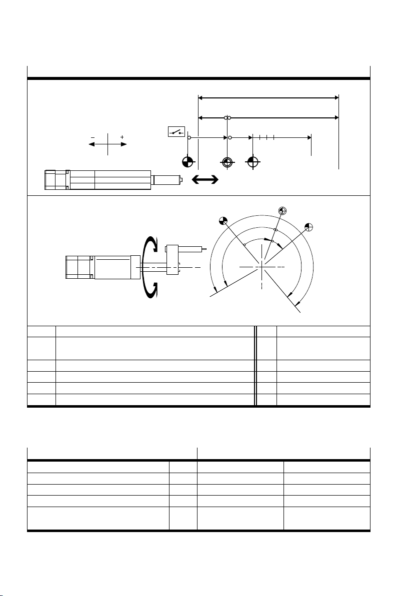
2.7.2 Homing methods to a fixed stop
Homing to a fixed stop is only possible in closed-loop operation ( section 2.2.4).
The stop is detected by a motor shutdown in combination with a sharp rise in the motor current. The
parameters for stop detection can be set in FCT.
Homing m ethods to the stop
– Negative fixed stop (retracted end position)
REF
2
REF
+
AZ
1
– Positive fixed stop (extended end position)
REF
1
AZ
2
–
1 Homing: The drive moves to the fixed stop at the search speed (= reference point RE F).
2 Movement to zero: the drive moves from the reference point REF to the axis zero point AZ.
Tab. 2.3 Homing to the stop
Note
Material damage due to moved measuring reference system
In the event of greatly reduced dynamic values (low maximum motor current) combined
with high travelling resistance (e.g. due to frictional grip), there is a danger that the
drive will come to a standstill and the controller will recognise a stop incorrectly.
A movement to zero should be executed when homing to a fixed stop ( section 2.7.6)
in order to exit the stop position. Otherwise the drive could be driven continuously
against an elastic stop, which would result in a strong temperature increase and eventually lead to the controller shutting down.
If the system does not have a stop (axis of rotation), the homing run will never be completed, i.e. the drive will run continuously at the parameterised search speed.
REF
22 Festo – GDCP-CMMO-ST-EA-SY-EN – 1301a – English
Page 23
2Overview
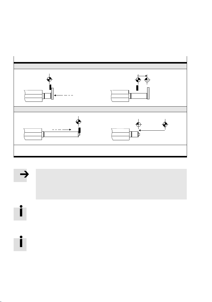
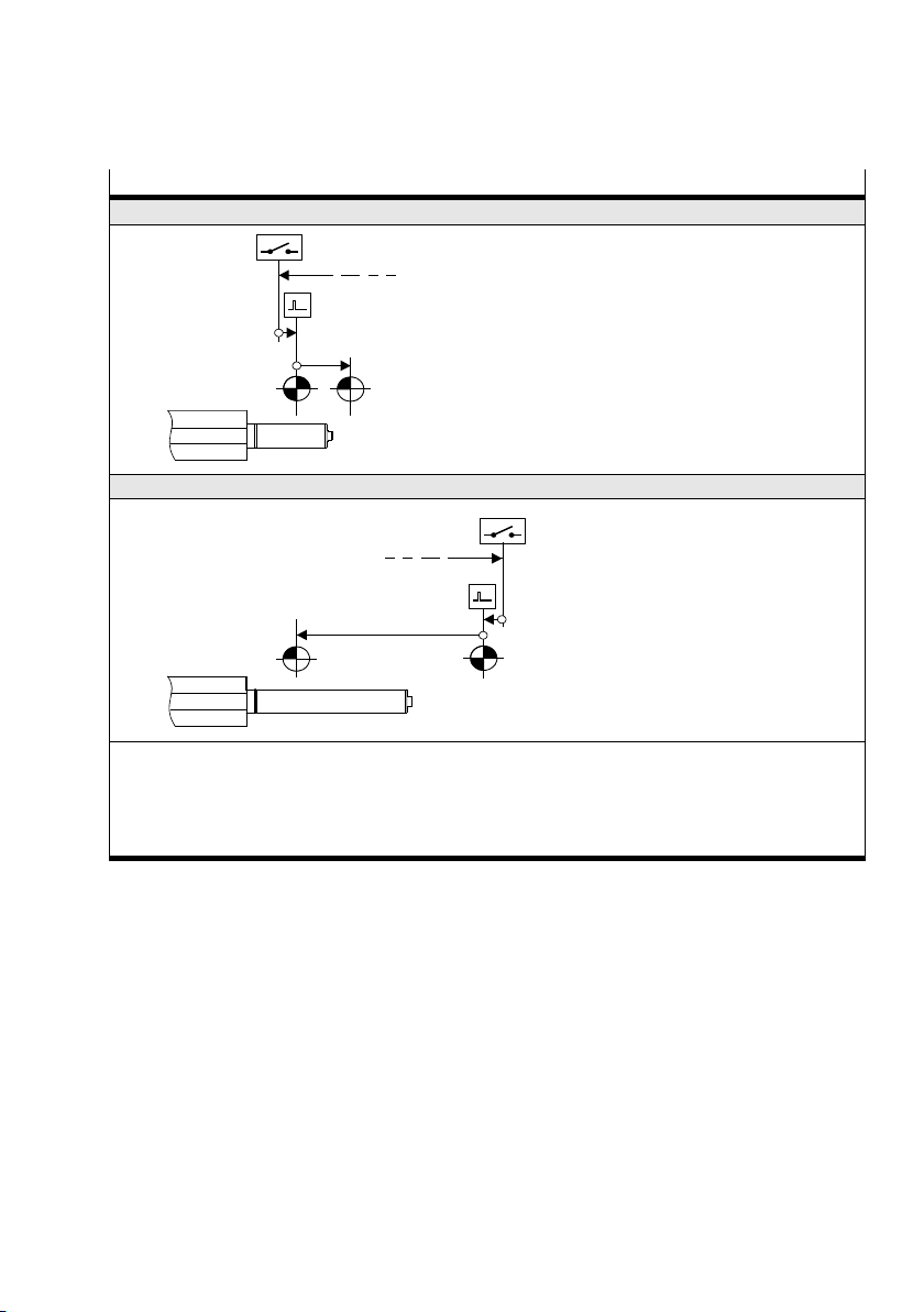
2.7.3 Homing methods to switch with/without index search
Homing methods to switch
– Direction: negative
1
2
+
REF
AZ
– Direction: positive
1
2
AZ
REF
1 The drive runs to the switch at the search speed, turns around and moves slowly at creep speed
in the reverse direction. The reference point REF is at the switch-off point of the switch or on the
following index pulse (depending on parameterisation).
2 Optional movement to zero: The drive runs from the reference point REF at positioning speed to
the axis zero point AZ.
Tab. 2.4 Homing to switch
For closed-loop operation ( section 2.2.4):
A distinction is made between the following options:
1. At the start of the homing run th e switch is already actuated.
In this case, the drive runs counter to the parameterised homing direction.
2. The switch is only found after the start of the movement.
In this case, the drive initially runs in the parameterised homing direction, turns after locating the
switch edge and moves in the reverse direction.
3. The drive moves against a stop before a switch is found.
In this case, the drive reverses and searches for the switch in the reverse direction. If a switch is
found, the drive moves through the complete switching range.
Festo – GDCP-CMMO-ST-EA-SY-EN – 1301a – English 23
Page 24

2Overview
In all cases the reference point is either at the switch-off point or on the following index
pulse (dependent on the homing m ethod selected).
For the last case: If a switch is not found in the reverse direction before a stop is
reached, the homing run is aborted with an error message.
If no switch is found at all and no stop is available, the homing run will never be completed, i.e. the drive will run continuously at the parameterised search speed.
For a homing run with index search: If no index pulse is found during the index search
over more than one motor rotation, the homing run is aborted with an error message.
For open-loop operation ( section 2.2.4):
The homing run in open-loop operation is generally executed in the same way as in closed-loop operation. However, the following special features apply:
– Stops are not detected
– An index search is not possible
– If a switch has not been found after a certain period of time, the homing run is aborted with an
error message. This timeout time can be set in FCT (“Homing” panel, “Settings” tab). The drive
therefore must always be positioned before the start of a homing run so that it can find the switch.
2.7.4 Homing method “current position”
The current position becomes the reference position. Apart from an optional movement to zero
( section 2.7.6), no positioning motion is executed.
In open-loop operation ( section 2.2.4) without a reference switch, this is the only possible homing
method.
2.7.5 Automatic homing (valve profile)
An “automatic homing run“ can be parameterised in the valve profile (FCT: “Homing” panel,
“Settings” tab).
This is executed automatically if the drive is not referenced at the start of a position record. The
started position record is then executed.
The automatic homing run is aborted if the position record input is reset again before the automatic
homing run has been executed completely.
24 Festo – GDCP-CMMO-ST-EA-SY-EN – 1301a – English
Page 25

2Overview
2.7.6 Movement to zero
A movement to zero is possible after a homing run. This is where the drive moves to the parameterised
axis zero point after finding the reference point.
Whether or not a movement to zero is executed can be defined as a homing run parameter in FCT. The
movement to zero is required when homing to the stop; the minimum offset to the axis zero point is
1 mm.
If a movement to zero is not executed, the drive remains at position (-1) * offset axis zero point. Make
sure that this position is not outside the software end positions.
If a movement to zero is to follow a homing run, “Motion complete” will only appear after
completion of the movement to zero. Motion Complete remains inactive between the
homing run and movement to zero.
A movement to zero should be executed when homing to the stop in order to exit the
stop position. Otherwise the drive could be driven continuously against an elastic stop,
which would result in a strong temperature increase and eventually lead to the controller
shutting down.
2.8 Monitoring functions
A complex system of sensors and monitoring functions ensures operational reliability:
– Voltage monitoring: detection of undervoltages and overvoltages in the logic and load voltage
supply.
– Temperature monitoring: output stage and CPU temperature in the CMMO-ST.
2
–I
t monitoring/overload protection
– Software end position recognition
– In the binary profile: contouring error monitoring (e.g.in the event of sluggishness or overloading of
the drive).
Festo – GDCP-CMMO-ST-EA-SY-EN – 1301a – English 25
Page 26

2Overview
2.9 Safety aspects
Note
Check within the framework of your EMERGENCY STOP procedures to ascertain the
measures that are necessary for switching your machine/system into a safe state in the
event of an EMERGENC Y STOP.
• If an EMERGENCY STOP circuit is necessary for your application, use additional, separate safety
limit switches (e.g. as normally closed limit switches wired in series).
• Use hardware limit switches or, if required, mechanical safety limit switches and fixed stops or
shock absorbers as appropriate in order to make sure that the axis always lies within the permitted
positioning range.
• Note the following points:
Action
Cancellation of
the ENABLE signal
on the I/O
interface
Switching off the
load voltage
Behaviour
– Without brake/clamping unit:
The drive brakes with the quick stop ramp (Quick stop). The controller
output stage is then switched off. The effective load could possibly slide
down if mounted in a vertical/incline d position.
– When using a brake/clamping unit:
If the drive moves when ENABLE is cancelled, then it will initially be brought
to rest using Quick Stop deceleration. As soon as the drive has come to a
standstill, the brake output is reset: the brake/clamping unit closes.
Simultaneously, the switch-off delay time begins to run. The CMMO-ST still
controls the position. The controller end stage is switched off after the
switch-off delay.
The load voltage is switched off. The effective load on the drive may continue to
move due to inertia, or it will fall if mounted in a vertical or sloping position.
For STO function: separate document GDCP-CMMO-ST-STO-…
26 Festo – GDCP-CMMO-ST-EA-SY-EN – 1301a – English
Page 27
3Mounting
3 Mounting
3.1 General instructions
Caution
Uncontrolled drive motion may cause personal injury and material damage.
• Switch off the power supplies prior to any assembly, installation or maintenance
work and prevent them from being restarted accidentally.
Caution
If a drive is mounted in a sloping or vertical position, loads may fall and cause personal
injury.
• Check whether external safety measures are necessary (e.g. toothed latches or
moveable bolts).
This will prevent the work load from sliding suddenly if there is a voltage failure.
Note
When mounting the controller on the machine:
• Observe the IP protection class of the controller and the connectors/cables.
Also observe the operating instruction(s) for the drive and the instructions provided with
any additional components (e.g. assembly instructions for t he cables concerning bending
radii or suitability for use with energy chains).
Festo – GDCP-CMMO-ST-EA-SY-EN – 1301a – English 27
Page 28
3Mounting
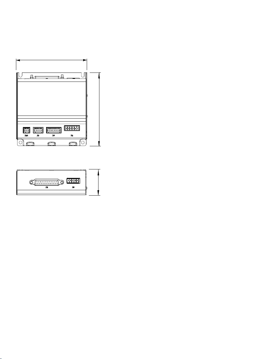
3.2 Dimensions of the controller
108 mm
113 mm
39 mm
Fig. 3.1 Dimensions of the controller
28 Festo – GDCP-CMMO-ST-EA-SY-EN – 1301a – English
Page 29

3Mounting
3.3 Mounting the controller
You can mount the controller in one of two ways:
1. Threaded c onnection on a flat surface
2. H-rail mounting
3.3.1 Fitting
You will need 3 or 4 M4 screws, with washers/spring washers if necessary. If a H-rail clip is mounted,
you can remove it.
The following figure shows the location of the holes and recesses that can be used for mountingthe
controller:
12
1
1 Mounting with 4 screws to the base
(lying flat)
2 Mounting on the side with 3 screws
(vertical)
Fig. 3.2 Mounting with screws
When mounting on the side ( 2 ): To exchange the controller, you only need to loosen the
3 screws by a few rotations, after which the controller can be tilted out.
Festo – GDCP-CMMO-ST-EA-SY-EN – 1301a – English 29
Page 30
3Mounting
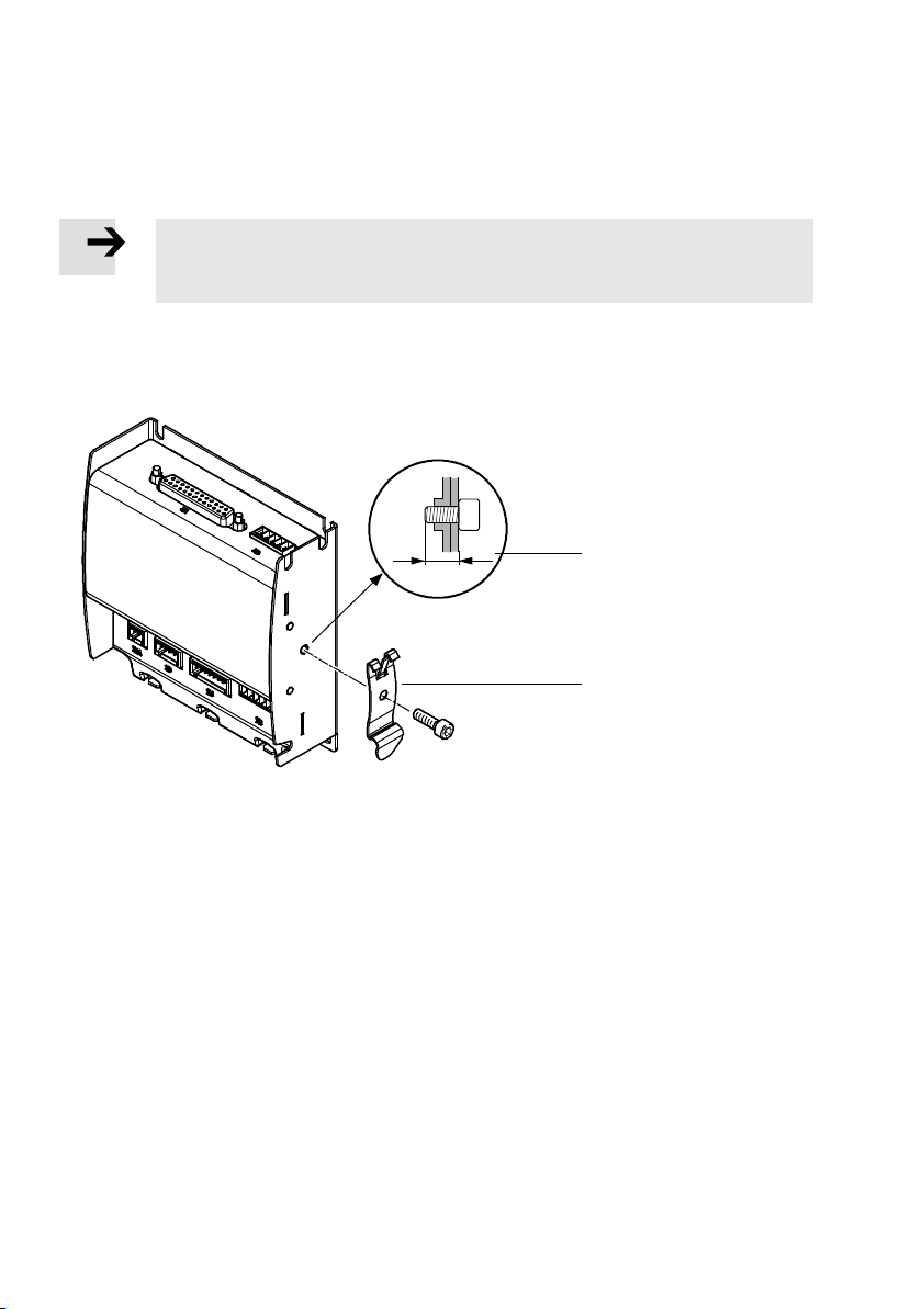
3.3.2 H-rail mounting
1. Mount an H-rail (mounting rail in accordance with IEC/EN 60715: TH 35– 7.5 or TH 35– 15).
2. If not already mounted: Screw the H-rail clip 1 to the side of the controller ( Fig. 3.3).
Note
When using another screw: Please observe the maximum permitted screw-in depth of
5 mm.
3. Hang the CMMO on the H-rail as follows:
• by inserting the top into the hooks in the clip first, then
• press the H-rail downwards until the CMMO clicks into place.
2
max. 5 mm
1
1 H-rail clip 2 Maximum screw-in depth
Fig. 3.3 H-railmounting
30 Festo – GDCP-CMMO-ST-EA-SY-EN – 1301a – English
Page 31

4 Electrical installation
4 Electrical installation
4.1 Overview
Caution
Uncontrolled drive motion may cause personal injury and material damage
• Switch off the power supplies prior to any assembly, installation or maintenance
work and prevent them from being restarted accidentally.
Caution
Faulty pre-assembled lines may destroy the electronics and trigger unexpected movements of the motor.
• When wiring the system only use t he supplied connectors and pref erably the cables
that are listed as ac c essories ( Tab. 4.1 ) .
• Lay all flexible lines so that they are free of kinks and free of mechanical stress; if
necessary use chain link trunking.
If unused plug connectors are touched, there is a danger that damage may occur to the
CMMO or to other parts of the system as a result of electrostatic discharge (E S D). Place
protective caps on unused terminals to prevent such discharges.
Note
To ensure compliance with EMC safety:
The maximum length of the individual cables should not exceed 30 m.
The project engineeringperformance data relates to a maximum cable length of 10 m.
To ensure compliance with the IP protection class (if required):
• Please note that the specified IP protection class is only achieved with a full plug
and cable assignment.
Festo – GDCP-CMMO-ST-EA-SY-EN – 1301a – English 31
Page 32

4 Electrical installation
1
2
3
45 6
1 Power supply (X9)
2 Higher-order controller (PLC/IPC) (X1)
3 Ethernet (X18)
7
5 STO ( X3)
6 Encoder (X2)
7 Motor (X6)
4 Reference switch (X1A)
Fig. 4.1 Connections on the CMMO-ST
)
Port
Cable and Festo type code
1
1 Power (X9) To be prepared by the customer
2 PLC/IPC (X1) Connecting cable: NEBC-S1G25-K-…-N-S1G25
Control cable: NEBC-S1G25-K-3.2-N-LE25
Connection block: NEBC-S1G25-C2W25-S7
Plug: N EBC-S1G25-C2W25-S6
3 Ethernet (X18) Standard network c able, RJ45 plug connector; c ategory 5 or higher
4 Reference switch (X1A) See Festo catalogue
5 STO (X3) To be prepared by the customer
6 Encoder (X2) Encoder cable
– NEBM-M12G8/W8-E-…-LE (G = straight; W = angled)
7 Motor (X6) Motor cable
– NEBM-S1W15-E-…-Q7: for motors with 15-pin plug
– NEBM-S1W9-E-…-Q5: for motors with 9-pin plug
– NEBM-M12G8-E-…-Q5: for size 28 motors
1) Specifications status August 2012. Only the current specifications in the Festo catalogue are relevant: www.festo.com
Tab. 4.1 Overview of cables (accessories)
32 Festo – GDCP-CMMO-ST-EA-SY-EN – 1301a – English
Page 33

4 Electrical installation
Observe the tightening torques specified in the documentation for the cables and plugs
used. The assortment of plugs supplied with the CMMO-ST is also available under the
type code NEKM-C-10.
4.2 Power supply [X9]
Port Pin Function
1 – Do not connect!
51
2 – Do not connect!
X9
51
Tab. 4.2 Port X9 “Power” (power supply)
Caution
Damage to the device
With port X9, always pay attention to the correct pin number corresponding to the plug
location on the device.
• Make sure that Pin 1 and Pin 2 are not connected.
3 Logic voltage +24 V supply of the control
electronics
4 Reference
potential
5 Load voltage +24 V supply of the power
0 V reference potential for load
voltage, logic voltage, STO and
controller interface
output stage and the motor
Festo – GDCP-CMMO-ST-EA-SY-EN – 1301a – English 33
Page 34

4 Electrical installation
Protection against electric shock (protection against direct and indirect contact) is guaranteed in
accordance with IEC/DIN EN 60204-1 by using PELV circuits (Electrical equipment of machines, general
requirements).
War n ing
• Use only PELV circuits in accordance with IEC/DIN EN 60204-1 (protective extra-low
voltage, PELV) for the electrical power supply.
Also comply with the general requirements for PELV circuits laid down in
IEC/DIN EN 60204-1.
• Use only power units which guarantee reliable electrical isolation of the operating
voltage as per IEC/DIN EN 60204-1.
Caution
Damage to the device
The power supply inputs have no special protection against overvoltage.
• Make sure the permissible voltage tolerance is never exceeded.
Technical data of the voltage supply: ( appendix A.1).
4.3 Functional earth
The metal sub-base of the CMMO-ST is used as a functional earth. It is galvanically isolated from the
power supply and, among other things, ensures EMC safety.
Note
• Connect the metal sub-base of the CMMO-ST to the earth potential with low
impedance (short cable with large cross section).
This prevents interference from electromagnetic sources and ensures electromagnetic
compatibility in accordance with EMC directives.
34 Festo – GDCP-CMMO-ST-EA-SY-EN – 1301a – English
Page 35

4 Electrical installation
4.4 I/O interface [X1]
Communicationwith the higher-order controller (PLC/IPC) occurs via the I/O interface.
Connection to the CMMO
14 25
1
PNP
Pin 1 2 … 11 12 13 14 15 16 17 18 19 20 21 22 23 24 25
I/O 1 2 … 11 1 2 3 4 5 6 7 8 9 10 11 – +24 V 0V
Inputs Outputs – Out GND
Tab. 4.3 Por t X1
Pin 24 and pin 25 can be used to switch an input ( illustration in Tab. 4.3):
– PNP version: Pin 24 at input
– NPN version: Pin 25 at input
Caution
Damage to the device
Pin 24 and pin 25 are not short circuit proof.
The functional description of the I/O interface, dependent on the selected profile, can be
found in the Commissioning chapter.
24
X1
NPN
13
25
Festo – GDCP-CMMO-ST-EA-SY-EN – 1301a – English 35
Page 36

4 Electrical installation
4.4.1 Electrical specifications of [X1]
The following specifications apply to both the PN P and NPN variants of the CMMO-ST.
Specifications for the I/O controller interface
Signallevel Based on EN 61131-2, type 1
Inputs
Scanning rate 1ms
Input current at nominal input voltage Typically 2 mA per input
Max. permissible input voltage 29 V
Galvanic isolation No
Outputs
Maximum Current 0.1 A per output
Overload protection Protected against short circuits
Pin 24 (24 V carried out)
Overload protection No (not protected aga inst short circuits). Only use for
switching inputs. Max. 0.1 A.
Tab. 4.4 Specificationsfor the I/O controller interface
4.5 Reference switch [X1A]
Port Pin Function
1 +24 V logic Voltage output for supplying the
13
reference switch (from X9). Not
protected against short circuits.
X1A
2 Signal Voltage input: +24 V with closed or
open reference switch contact
(depending on switch type).
3 0V Reference potential
13
T ab. 4.5 Connection X1A reference switch
The types listed in the Festo catalogue for the respective drive are suitable for use as
reference switches ( www.festo.com).
36 Festo – GDCP-CMMO-ST-EA-SY-EN – 1301a – English
Page 37

4 Electrical installation
4.6 STO [X3]
The STO safety function (“Safe Torque Off ”) is described in detail in the document
GDCP-CMMO-ST-STO-…
The STO function should only be used in the manner described in this document.
Port
1
5
X3
15
T ab. 4.6 Connection X3 STO
Pin Function
1 +24 V logic Logic voltage output (from X9)
2 STO 1 Channel 1: switch off the supply
voltage
3 STO 2 Channel 2: switch off the supply
voltage
4 Diagnostics 1 The diagnostic contacts are
potential-free.
The diagnostic contact is low
5 Diagnostics 2
impedance if the STO function has
been requested and activated via
two channels.
Festo – GDCP-CMMO-ST-EA-SY-EN – 1301a – English 37
Page 38

4 Electrical installation
4.7 Encoder [X2]
An incremental encoder with signals in accordance with RS422 can be connected at connection X2.
Port
18
X2
18
1) Each 5 V and Ri = approx. 120 Ω
T ab. 4.7 Connection X2 encoder
Pin Function
1)
1 A/
1)
2 A/
1)
3 B/
1)
4 B/
1)
5 N/
1)
6 N/
7 5V(±10%) Supply of the encoder.
8 0V Reference potential
Incremental encoder signal A+,
Positive polarity
Incremental encoder signal A–,
Negative polarity
Incremental encoder signal B+,
Positive polarity
Incremental encoder signal B–,
Negative polarity
Increment encoder signal zero pulse,
positive polarity
Increment encoder signal zero pulse,
negative polarity
Max. 100 mA permissible.
Not protected against short circuits.
4.8 Motor [X6]
Port Pin Function
1 String A Connection of the two motor strings
1
X6
1
Tab. 4.8 Connection X6 motor
38 Festo – GDCP-CMMO-ST-EA-SY-EN – 1301a – English
6
2 String A/
3 String B
4 String B/
5 BR+ Connection of the holding brake
Short circuit and overload-proof.
24 V, max. 1.4 A 33 W.
BR– = GND,
BR+ is switched (24 V load)
6
6 BR–
Page 39

5 Commissioning
5 Commissioning
5.1 Safety regulations
War n ing
Risk of injury.
Electric axes move with high force and at high speed. Collisions can lead to serious
injury to people and damage to components.
• Make sure that nobody c an reach into the operating range of the axes or other
connected ac tuators – e.g. with a protective grille – and that no objects lie in the
positioning range while the system is still connected to a power supply.
Caution
Unexpected movement of the drive due to incorrect or incomplete parametrisation!
When the CMMO-ST is switched on, the I/O control interface is activated as standard.
• Make sure that there is no ac tive ENABLE signal when switching on the CMMO-ST on
the I/O control interface.
• Parameterise the entire system completely before activating the output stage with
ENABLE.
Caution
When c ontrol via the web browser or FCT is activated, the drive cannot be stopped with
the PAUSE/STOP input or the ENABLE input of the I/O control interface.
Caution
The CMMO-ST cannot detect if the connection to the web browser has been interrupted.
Movements that have been started via the web browser c an no longer be stopped by
using the web browser if the Ethernet connection is interrupt ed during the movement.
• Only use the web browser if you are sure that accidental movements will not result in
any damage.
Caution
Housing surfaces can reach high temperatures. Contact with the surface may result in
shock and uncontrolled reactions wit h subsequent damages.
• Make sure that the surface cannot be touched accidentally and inform your operating and maintenance staff of the possible hazards.
Festo – GDCP-CMMO-ST-EA-SY-EN – 1301a – English 39
Page 40

5 Commissioning
Note
The CMMO-ST does not carry out any positioningjobs/records if it is not referenced.
• Carry out a homing run in the following cases to anchor the measuring reference
system to the reference point:
– every time the logic voltage supply is switched on or after every failure
– after changing the homing method, the axis zero point, the direction of rotation
Note
If the axis zero point is modified:
Existing software end positions and the target positions in the record table will be
shifted together with the axis zero point.
• Adjust the software end positions and the target positions if necessary.
Note
Damage to components when the permissible impact pulse is exceeded.
• Operate the drive only with the permissibleload ( operating instructions for the
drive).
• If necessary, limit the maximum current (motor force) when travelling to the stop.
Note
Interruption of ongoing tasks due to inadequate load voltage supply.
• Make sure that the tolerance of the load voltage supply can be maintained at full
load directly on the voltage terminal of the CMMO-ST ( section 4.2).
or the encoder resolution
40 Festo – GDCP-CMMO-ST-EA-SY-EN – 1301a – English
Page 41

5 Commissioning
5.2 Ethernet interface (RJ-45)
5.2.1 Delivery status of the CMMO-ST
Note
The CMMO-ST is equipped during production with a active DHCP server (Dynamic Host
Configuration Protocol).
• Before adding the CMMO-ST to an existing network, please observe the instructions
in section 5.2.5 “Initial start-up”, as these will enable you to prevent network malfunctions.
Computers with an active DHCP client ac c ept all DHCP servers. If two DHCP servers are activated in a
network by mistake, the functionality of the network may be impaired.
CMMO-ST network settings
Parameters Val u e
IP 192.168.178.1
DHCP server Active
Port Web browser: 8 0
FCT: 7508
CVE (= Control via Ethernet): 49700
Subnet mask 255.255.255.0
Gateway 0.0.0.0 (none)
Tab. 5.1 Network settings: delivery status
5.2.2 DHCP or fixed IP address
Behaviour of the DHCP server
The DHCP server of the CMMO-ST is intended to establish a direct connectionbetween the CMMO-ST
and an individual computer. It is not intended to supply larger networks with IP addresse s.
It assigns IP addresses in a range of 192.168.178.110 … 192.168.178.209 and the subnet mask
255.255.255.0. A gateway is not assigned.
Additional configuration options
DHCP client
The CMMO-ST can also be configured as a DHCP c lient. It then obtains its IP address from a DHCP
server in your network.
Specifying a fixed IP address
Alternatively you can also assign a fixed IP address to the CMMO-ST.
These settings can be adjusted, if required, in FCT ( section 6.4.3).
Festo – GDCP-CMMO-ST-EA-SY-EN – 1301a – English 41
Page 42

5 Commissioning
After making changes to the network configuration of the CMMO-ST, it will need to be
restarted in order for the changes to take effect.
5.2.3 Safety in the network
Caution
When c onnecting the CMMO-ST to existing networks (e.g. the Internet): any unauthorised or accidental access to the CMMO-ST c ould result in unforeseeable behaviour.
• Only use the CMMO-ST in subnets that are protected from external unauthorised
access, e.g. by using net w ork security components (special gateways/firewalls).
Use a password if you want to prevent ac c idental access to the CMMO-ST (in FCT: menu
option “Component” / Online / Password).
5.2.4 Timeout
The CMMO-ST detects if the connection to the FCT software has been interrupted and it behaves in
accordance with the settings parameterised in FCT under “Error management” (error number 0x32).
The timeout period is typically 1 s, but it can be longer in slow networks, as the timeout period is
dynamically adapted to the transmission rate.
Caution
The CMMO-ST cannot detect if the connection to the web browser has been interrupted.
Movements that have been started via the web browser c an no longer be stopped by
using the web browser if the Ethernet connection is interrupt ed during the movement.
• Only use the web browser if you are sure that accidental movements will not result in
any damage.
42 Festo – GDCP-CMMO-ST-EA-SY-EN – 1301a – English
Page 43

5 Commissioning
5.2.5 Initial start-up via Ethernet
The CMMO-ST will need to be connected directly to a computer/laptop for the initialstart-up phase.
The CMMO-ST cannot be connected immediately to a network during the initial start-up phase, as its
active DHCP server could result in network malfunctions.
1. Switch on the CMMO-ST and connect it to your computer/notebook by using a standard Ethernet
cable (connector: RJ-45). The cable type, i.e. whether it has a straight or crossed connection, is
detected automatically. The DHCP server in the CMMO-ST will now assign an IP address to your
computer, enabling you to access the CMMO-ST (requirement: a DHCP client is active on your computer = default setting for most computers).
Fig. 5.1 Initialstart-up via direct connection
2. Launch your web browser (activate Internet Explorer >6; Firefox >3; JavaScript) and type the IP
address of the CMMO-ST into the address bar (default setting: 192.168.178.1). The CMMO-ST
website will now appear ( section 5.3).
3. Alternatively to the web browser, you can also install the FCT software fromtheCD.TheFCTsoftware makes more complex configurations possible than the web browser does ( section 5.4).
If you cannot establish a connection to the CMMO-ST: section 6.4.3.
Festo – GDCP-CMMO-ST-EA-SY-EN – 1301a – English 43
Page 44

5 Commissioning
5.3 Commissioning via web server
The web server integrated in the CMMO-ST provides access to an English-language parameterisation
and commissioning website, which you can call up with a web browser. Commissioning via the web
server is possible for selected products, i.e. axis mechanisms optimised by Festo.
5.3.1 What does the web server enable?
Parameter files
Uploading and downloading parameter files for initial start-up or for use as backup files.
Homing
Starting a homing run in accordance with the homing method parameterised in the CMMO-ST (default
settings: Tab. 5.2).
The homing run can only be started; a c hange of the homing method must take place in FCT.
Jogging
Jog mode in both directions.
Teaching
Teaching of up to 7 absolute target positions; parametrisation of speed and acceleration of the resulting position records.
Relative target positionscannot be taught. Corresponding position records, however, c an be entered by
hand.
Positioning
Starting and stopping the 7 position records.
I/O
Display of the electro-physical status of the inputs and outputs of the I/O interface.
Diagnostics
Read-out of the diagnost ic memory and display of the most important controller statuses.
Identification
Wave function: Activating a radio button (“Identify this CMMO”, Fig. 5.2) causes the decimal point in
the 7-segment display of the currently connected CMMO-ST to start flashing.
5.3.2 Parameter files
The parameter files support the initial start-up of your drive. The parameter files corresponding to the
respective drive type can be found:
– on the supplied CD
– on the Festo Support Portal fo r download
– as “Cloud” parameter on the Festo Internet Server
44 Festo – GDCP-CMMO-ST-EA-SY-EN – 1301a – English
Page 45

5 Commissioning
The parameter files for EPCO drives include the following settings, for example:
Parameters
Default setting
Control Profile Valve profile (7), i.e. 7 position records can be
parameterised via web ser vers, for example:
– target position (absolute/relative)
– travel speed
– acceleration (start up/braking)
– reductionofthefeedforce(forcelimit)
Reference travel method (controlled operation) – negative stop (motor-side) with movement to
zero
– force limit for stop detection
– movement to zero 3 mm
Reference travel speeds:
– Search speed
– 2.5 % of the maximum speed
1)
(travel to the switch/stop)
– Creep speed
– 1.25 % of the maximum speed
1)
(travel to the switch edge/index pulse)
– Positioning speed
– 5 % of the maximum speed
1)
(travel to the axis zero point)
Dimensional reference system:
– Position of the axis zero point
– Software limit switch (negative)
– Software limit switch (positive)
– +3mmfromthemechanicalstop
––3mm
– (stroke length – 3 mm)
Jogging
– Speed phase 1 (slow travel)
– Duration of phase 1
– Speed phase 2 (fast travel)
– 1.25 % of the maximum speed
–2s
– 5 % of the maximum speed
1)
1)
Condition for the “Position reached” message
(Motion complete)
–Targetwindow
– Message Delay
– +/- 0.2 mm
– 100 ms
STOPbuttoninthewebbrowser Deceleration ramp of t he current function
(e.g. of the current record)
Quick Stop (triggered by the controller,
70 % of the maximum deceleration
1)
e.g. in the event of a serious error)
1) The maximum values for speed, acceleration, force, etc. depend on the mechanical system used and can be read via FCT if
required.
Tab. 5.2 Valve profile: default values (EPCO)
All other settings of the parameter files can be read in FCT as needed.
Festo – GDCP-CMMO-ST-EA-SY-EN – 1301a – English 45
Page 46

5 Commissioning
5.3.3 Initial start-up with the web server
If you have accessed the CMMO-ST website in accordance with section 5.2.5, you will initially be
presented with the diagnostics page:
Fig. 5.2 Website: diagnostics
46 Festo – GDCP-CMMO-ST-EA-SY-EN – 1301a – English
Page 47

5 Commissioning
1. Switch to the parameterisationpage by clicking <Parameters> at the far right.
2. Enter the type code of your EPCO drive in the uppermost text box in accordance with the rating
plate, and click <Search> to download a suitable parameter file from the Festo website (Internet
access required). Caution: Incomplete entry of the code may result in malfunctions, uncontrolled
behaviour and damage.
If you do not have a second network connection (e.g. WLAN/WiFi), you can continue to step 4 and
use the parameter file on the CD.
Fig. 5.3 Website: parameters
3. Click <Save> in the Windows dialogue window “Download file” to save the file to your computer.
4. Click <Browse> and select the downloaded parameter file in the dialogue window.
Fig. 5.4 Selecting a parameter file
5. Click the box next to “Device Control” to assume higher-order control.
Fig. 5.5 Assuming higher-order control
6. Click on <Download parameter set to CMMO>.
Fig. 5.6 Transferring a parameter file to the CMMO-ST
Festo – GDCP-CMMO-ST-EA-SY-EN – 1301a – English 47
Page 48

5 Commissioning
7. The following screen confirms the successful transmission. The parameter file is automatically
saved in the CMMO-ST.
Fig. 5.7 Download completed successfully
8. To teach position records: Switch to the parameter side again by clicking <Parameters> at the far
right. Then set the enable signal for the output stage by clicking the box next to “Control Enable”.
Fig. 5.8 Setting enable
9. First, start a homing run by c licking the <Start Homing> button (default setting: negative stop
(motor-side) with movement to zero Tab. 5.2).
Then click the <Jog neg.> or <Jog pos.> buttons to move the drive in a negative or positive direction
(in this example: to position 10.00 mm).
Fig. 5.9 Jogging
10. Select “Positioning to absolute position” from the first drop-down menu in the position record table
and then click <Teach Pos>.
Fig. 5.10 Teach
11.Move to a different position and teach this position to position record no. 2.
12. Enter the additional positions. Relative target positions can be entered by hand, but they cannot be
taught.
48 Festo – GDCP-CMMO-ST-EA-SY-EN – 1301a – English
Page 49

5 Commissioning
Fig. 5.11 Website: Parameters – Record Sets (1)
13.Adjust the valuesfor travel speed, acceleration and force limit.
Fig. 5.12 Website: Parameters – Record Sets (2)
Festo – GDCP-CMMO-ST-EA-SY-EN – 1301a – English 49
Page 50

5 Commissioning
Through the digital output “Force limit reached” (DOUT 11), reaching the parameterised
maximum force (“Torque”) can be displayed. In this way, with corresponding parameterisation, a load limit can be displayed at which the motor can no longer follow the
position sequence (following error). An additional following error message is not activated with these parameter records.
14.Click the <Download> button underneath the position record table in order to transfer the new
position records to the CMMO-ST.
15.To t e s t the taught position records: click the <Move to Pos.> button next to the desired position
record. The drive moves to the respective position.
Fig. 5.13 Executing position records
16.To permanently store the new position records in the CMMO-ST: remove the check mark next to
“Control Enable” and then click the <Store> button underneath the position record table.
Fig. 5.14 Saving position records in the CMMO-ST
5.3.4 Creating a parameter backup file
When parameterisation is complete you can c reate a backup copy of your parameters by using the web
browser. If you ever need to replace the CMMO-ST, you can import this paramete r file into the new
CMMO-ST. Re-parameterisationis therefore no longer required.
1. Establish a connection to the CMMO-ST and launch your web browser as described in section 5.2.5.
2. Click <Upload parameter set to PC>.
Fig. 5.15 Creating a backup copy
3. Click <Save> in the Windows dialogue window “Download file” to save the file to your computer. Give
the file a unique name (*.fpf = Festo Parameter File).
4. To import the parameter backup file into a new CMMO-ST: proceed as described in section 5.3.3
under points 4 ... 7.
The backup copy can also be created by using FCT (“Component / Online / Administer
recoveryfile...”).
50 Festo – GDCP-CMMO-ST-EA-SY-EN – 1301a – English
Page 51

5 Commissioning
5.4 Commissioning with FCT (Festo Configuration Tool)
The Festo Configuration Tool (FCT) is the software platform for configuring and c ommissioning different
components and devices from Festo.
The FCT consists of the following components:
– A framework as program start and entry point with uniform project and data management for all
supported device types.
– A plug-in for the special requirements of each device type (e.g. CMMO-ST) with the necessary
descriptionsand dialogues. The plug-ins are managed and star ted from the framework.
The FCT software provides more extensive configuration options than the web browser. The binary profile can be used in particular, which also enables jogging and teaching via the I/O interface, force mode,
speed mode and record linking.
The following pages only describe the first few steps in FCT. Implement all other steps in
accordance with the instructions in the integrated FCT help system.
5.4.1 Installing the FCT
Note
FCT plug-in CMMO-ST V 1.0.0 supports the motor controller CMMO-ST-…-IO with firmware version V 1.0.x
For later versions of th e CMMO-ST chec k whether an updated plug-in is available. If
necessary, consult Festo.
Note
Windows administrator rights are required for installing the FCT.
The FCT is installed on your PC with an installation program.
1. Close all programs.
2. Insert the “Festo Configuration Tool” CD into your CD-ROM drive. If Auto-Run is activated on your
system, the installation starts automatically and you can skip steps 3 and 4.
3. Select [Execute] in the Start menu (for Windows 7: see “Accessories” menu).
4. Enter D:\Start (if necessary replace D by the letter of your CD ROM drive).
5. Follow the instructions on the screen.
Festo – GDCP-CMMO-ST-EA-SY-EN – 1301a – English 51
Page 52

5 Commissioning
5.4.2 Starting the FCT
1. Connect the CMMO-ST to your PC via the Ethernet interface ( section 5.2.5).
2. Start the FCT:
double click the FCT ic on on the Desktop
–or–
In the Windows menu [Start], select the entry [Festo Software] [Festo ConfigurationTool].
3. Create a project in the FCT or open an existing project. Add a CMMO-ST to the project:
menu [Components] [Insert].
Instructions on parameterising and commissioning
FCT framework
Information on working with projects and on inserting a device in a project can be found in the help for
the FCT framework with the c ommand [Help] [Contents FCT general].
Plug-in CMMO-ST
The plug-in CMMO-ST fo r the FCT supports processing of all the steps necessary for commissioning a
CMMO-ST. The necessary parameterisation settings can be performed offline, i.e. without the CMMO-ST
being connected to the PC. This enables preparation for the actual c ommissioning process, e.g. in the
design office when a new system is being planned.
Additional information can be found in the plug-in help: command [Help] [Contents of
installed plug-ins] [ Festo (manufacturer name)] [CMMO-ST (plug-in name)].
Device control / master control
When the CMMO-ST is switched on, the I/O interface is ac tivated as standard.
Caution
Unexpected movements of the drive due to incorrect parameterising
• Make sure th ere is no active ENABLE signal when switching on the CMMO-ST on the
I/O interface.
• Parameterise the entire system completely before activating the output stage with
ENABLE.
In order for the FCT to control the connected CMMO-ST, the I/O interface of the CMMO-ST must be
deactivated and control must be enabled for the FCT. The status of the ENABLE I/O input then has no
effect.
• To do this, go to the “Project output” window, select the “Operate” tab and, under “Device
Control”, activate the “FCT” check box.
This deactivates the I/O control interface of the CMMO-ST and sets the controller enable for the FCT.
52 Festo – GDCP-CMMO-ST-EA-SY-EN – 1301a – English
Page 53

5 Commissioning
More information
Printed information
Youcan use one of the following options to be able to use the complete Help or parts thereof independently of a PC:
• Print individual pages or all of the pages in a book directly from the Help contents by using the
“Print” button in the Help window.
• Print a prepared version of the help in Adobe PDF format:
Printed version
FCT help
Directory File
...(FCT installationdirectory)\Help\ – FCT_de.pdf
(framework)
PlugIn help
(CMMO-ST)
...(FCT installationdirectory)\HardwareFamilies\
Festo\CMMO-ST\V...\Help\
– CMMO-ST_de.pdf
In order to use the printed version in Adobe PDF format, you will require Adobe Reader.
Festo – GDCP-CMMO-ST-EA-SY-EN – 1301a – English 53
Page 54

5 Commissioning
5.5 I/O interface
5.5.1 Profiles for s election
Two profiles are available for control of the CMMO-ST via the I/O interface:
Valve profile (7)
The valve profile is based on the control of pneumatic valves and is very easy to configure. Use this
profile if 7 position records are sufficient (simple positioning operation only).
Binary profile (31)
The binary profile uses 5 binary coded inputs and can therefore select 31 records (plus record 0 =
homing).
The following are also available:
– jogging and teaching
– Force mode
– Speed mode
–RecordLinking
Initial start-up
During the initialstart-up phase the valve profile is active. An initial start-up is thereby possible with
both a web browser and with FCT.
Change profile
A change between profiles must be effected using FCT. FCT ensures that no inconsistent states arise
when switching.
The web server only supports the valve profile. A change to the binary profile is not possible.
54 Festo – GDCP-CMMO-ST-EA-SY-EN – 1301a – English
Page 55

5 Commissioning
5.5.2 Properties of the valve profile (7)
Signal pairs
There are signal pairs comprising an input n and an output n, each of which re late to a particular position record. The corresponding position record is started by setting the input. The input must remain
active until the specified target is reached. When the target position (MC) is reached, the output is set.
As long as no other input is set, the output remains set even if the input is reset.
Change of position record
If the active input is changed while executing a position record, a change is made to the new position
record continuously without stopping. Sequence when changing a record: First, enable the input of the
new record, then disable the input of the first record(also refer to the timing diagrams).
Following error
If the drive comes up against a physical stop, it uses the parameterised torque to press against th e
stop until the input become s inactive. There is no following error monitoring in the valve profile.
Standstill monitoring
There is no standstill monitoring in the valve profile, i.e. after completion of a position record the drive
can be shifted by external forces without it being reported to the PLC.
–Inclosed-loop operation the position controller tries to hold the drive in position, but it only does
this up to the maximum peak current that has been parameterised. In critical circumstances use the
PRN variant for relative positioning tasks (positioning relative to the last target position).
–Inopen-loop operation the drive is held in position with the parameterised holding force. Make sure
that the holding force is sufficient to hold the position.
Automatic homing
A homing run can be executed automatically in the valve profile if the drive is not referenced at the start
of a position record, section 2.7.5.
Festo – GDCP-CMMO-ST-EA-SY-EN – 1301a – English 55
Page 56

5 Commissioning
Assigning the inputs and outputs
Valve profile: Inputs
Input Designation Des cription
1 Position record 1
1)
Start and execute position record 1 as long as input 1 remains
active.
2 Position record 2
1)
Start and execute position record 2 as long as input 2 remains
active.
3…6 …
7 Position record 7
1)
…
1)
Start and execute position record 7 as long as input 7 remains
active.
8 REF Starts a homing run in accordance with the parameterised
method.
9 BRAKE An active input overrides automatic brake control and opens the
closed brake. This input can be used to open a closed brake,
however, it cannot be used to close an open brake (prevention of
brake wear as a result of faulty application).
10 ENABLE After setting this enable signal the CMMO-ST assume s control of
the connected drive.
11 RESET A reported error is reset (if possible).
1) If the drive is not referenced at the start of a position record, a homing run can be started automatically section 2.7.5.
Tab. 5.3 Valve profile: Assignment of inputs
56 Festo – GDCP-CMMO-ST-EA-SY-EN – 1301a – English
Page 57

5 Commissioning
Valve profile: Outputs
Output Designation Description
1 Position 1 reached The target position of the respective position record has been
2 Position 2 reached
reached.
3…6 …
7 Position 7 reached
8 In Zone
( section 5.9.1)
The drive is located within the position zone of the active position
record parameterised in FCT. The position zone is formed by the
position comparators.
If the input is inactive, output 8 remains set. If, however, the drive
is pushed out of position and then returns, the output remains
inactive.
If another input is active, then the current position is compared
to its position zone and output 8 is set again depending on the
result.
9 Referenced After a successful homing run this output is set and remains set
foraslongasthedriveisreferenced.
10 Ready Drive is ready for operation. All requirements for starting a
position record are fulfilled (e.g. load voltage is present, ENABLE
is set, no serious error).
11 Torque Limit reached The parameterised torque/force limit has been reached.
Tab. 5.4 Valve profile: Assignment of outputs
Electrical specification of the inputs and outputs: section 4.4.1.
Festo – GDCP-CMMO-ST-EA-SY-EN – 1301a – English 57
Page 58

5 Commissioning
1) Valve profile: Switching on, homing
Vel
Pos1
Pos2
REF
ENABLE
RESET
Ready
Referenced
OnPos1
23
0
1
4
t
t
t
t
t
t
t
t
OnPos2
>1s
1 ENABLE
2 Start homing
3 Homing run ended
4 Reset REF
Fig. 5.16 Timing diagram: Valve profile – switching on, homing
58 Festo – GDCP-CMMO-ST-EA-SY-EN – 1301a – English
t
t
Page 59

5 Commissioning
Switching on
After switching on: Wait a second and then set t he inputs.
ENABLE
Set ENABLE input. The first time ENABLE is set after the switch-on procedure, th e drive conducts a
commutation angle search (duration: up to 2 seconds). Wait for Ready output.
Start homing
Start homing via REF input.
Homing run ended
Following successful completion of the homing run the Referenced output is set.
Reset REF
The REF input may only be reset after successful completion of the homing run.
Festo – GDCP-CMMO-ST-EA-SY-EN – 1301a – English 59
Page 60

5 Commissioning
2) Valve profile: Terminate record 1, start record 2
12 3 4
Vel
0
Pos1
Pos2
REF
ENABLE
RESET
Ready
Referenced
t
t
t
t
t
t
t
OnPos1
OnPos2
1 Start record 1
2 Cancel record 1
3 Start record 2
4 Destination 2 reached
Fig. 5.17 Timing diagram: Valve profile – terminate record 1, start record 2
60 Festo – GDCP-CMMO-ST-EA-SY-EN – 1301a – English
t
t
t
Page 61

5 Commissioning
Requirements
Drive is referenced and ready.
Start record 1
Record 1 is started by setting input Pos1.
Terminate r e c o r d 1
Record 1 is terminated if input Pos1 is removed. The output OnPos1 is not set in this example, as the
target position has not yet been reached.
Start record 2
Record 2 is started by setting input Pos2.
Destination 2 reached
After reaching the parameterised target position window and after expiration of the parameterised
damping time, the output OnPos2 is set.
Festo – GDCP-CMMO-ST-EA-SY-EN – 1301a – English 61
Page 62

5 Commissioning
3) Valve profile: Record switching
123
Vel
0
Pos1
Pos2
REF
ENABLE
RESET
Ready
Referenced
t
t
t
t
t
t
t
OnPos1
OnPos2
1 Start record 1
3 Destination 2 reached
2 Switching
Fig. 5.18 Timing diagram: Valve profile – record switching
62 Festo – GDCP-CMMO-ST-EA-SY-EN – 1301a – English
t
t
t
Page 63

5 Commissioning
Requirements
Drive is referenced and ready.
Start record 1
Record 1 is started by setting input Pos1.
Switch over
While record 1 is being executed, input Pos2 is set. The drive switches immediatelyto record 2.
Destination 2 reached
After reaching the parameterised target position window and after expiration of the parameterised
damping time, the output OnPos2 is set.
Festo – GDCP-CMMO-ST-EA-SY-EN – 1301a – English 63
Page 64

5 Commissioning
4) Valve profile: Acknowledging errors
123 45
Vel
0
Pos1
Pos2
REF
ENABLE
RESET
Ready
Referenced
t
t
t
t
t
t
t
OnPos1
OnPos2
1 Start record 1
2 Error
4 Restart record 1
5 Destination 1 reached
3 Acknowledge error
Fig. 5.19 Timing diagram: Valve profile – acknowledging errors
64 Festo – GDCP-CMMO-ST-EA-SY-EN – 1301a – English
t
t
t
Page 65

5 Commissioning
Requirements
Drive is referenced and ready.
Start record 1
Record 1 is started by setting input Pos1.
Error
An error occurs, e.g. a following error. In this example, this malfunction has been parameterised as an
error and, as a response, a deceleration is effected with the quick stop ramp (Quick stop).
The Ready output is reset.
The drive brakes with the quick stop ramp and remains stationary.
Acknowledge error
The error is acknowledged by setting the RESET input. After setting this input the parameterised time
for the switch-on delay of the holding brake starts to run. When this time has expired the Ready output
is set again.
Restar t rec ord 1
When the input Pos1 has been reset, record 1 can be restarted by setting this input again.
Destination 1 reached
After the parameterised target position window is reached and the parameterised damping time has
expired, the output OnPos1 is set.
Festo – GDCP-CMMO-ST-EA-SY-EN – 1301a – English 65
Page 66

5 Commissioning
5.5.3 Properties of the binary profile (31)
31 commandrecords
31 command records can be selected via 5 inputs (plus record 0 = homing).
These 31 command records can be positioning records, force records or speed records.
Jogging
By using manual “jogging” (i.e. setting a particular input signal at the I/O interface) a position can be
approached, which is then transferred to an absolute position record by “teaching”.
Teaching
When teac hing via the I/O interface you can set whether the value is stored permanentlyor only
temporarilyuntil the next restart procedure (FCT: “Digital I/O”, “Automatic storage” page).
Teaching via the I/O interface is only intended for commissioning; the flash memory is not suitable for
permanent teaching during operation ( section 2.4.11).
Record linking
When a step enabling condition occurs, another record is automaticallystarted after the end of the
current record ( section 5.8).
Recordswitching
While a command record is being executed, another command record can be switched to at any time;
in this process the higher-order controller (PLC) pre-selects a new command record and sends a new
START signal ( section 5.7).
Pause (intermediate stop)
An “intermediate stop” is triggered on the CMMO-ST via the I/O interface. This works as follows:
1. If the signal at digital input no. 7 “PAUSE” is removed during a record (= physical 0 signal), the drive
brakes at the braking ramp that has been parameterised for this record and remains stationary. The
record remains active, “Motion complete” is not set.
2. A renewed setting of input no. 7 initially has no effect on the behaviour of the drive. The drive continues to remain stationary.
3. A new START signal results in the record running to the end.
4. If another record has been selected at the inputs after step 2, this is ignored.
5. If the RESET input is set after step 2, “Motion complete” appears, as the record is considered completed. If a new record is then selected and START is set, the new record is executed.
66 Festo – GDCP-CMMO-ST-EA-SY-EN – 1301a – English
Page 67

5 Commissioning
Assigning the inputs and outputs
The binary profile has two modes:
– You can execute records in Mode 0 (positioning mode, force mode or speed mode).
– You can jog and teach in Mode 1.
You can switch between the two modes by using input no. 8.
Binary profile: Inputs
DIN Mode 0: Normal operation Mode 1: Jogging and teaching
1 Record 0 … 31
(Record 0 =
2
homing)
3
These inputs are evaluated together.
Coding: Tab. 5.6.
Record 1 … 7
(Record 0 cannot
be taught)
These inputs are
evaluatedtogether.
Coding: Tab. 5.6.
4 JOG+ Jog positive
5 JOG– Jog negative
6 Start Starts a record. TEACH Transfer current position in
position record.
7 PAUSE Removal of the physical signal stops the drive
(this input is inverted, i.e. negative logic)
8 Mode 0 Normal operation Mode 1 Jog/teach
9 BRAKE Setting the input opens the brake. Only relevant if the controller is not
enabled, i.e. not in a “Ready” state.
10 ENABLE Activate/enable the controller, release brake.
11 RESET Acknowledge error - or - delete remaining path (if a position record has
been interrupted with input 7).
Tab. 5.5 Binary profile: Inputs
REF 1 2 3 4 5 6 7 8 9 10 … 31
DIN
1 0 1 0 1 0 1 0 1 0 1 0 … 1
2 0 0 1 1 0 0 1 1 0 0 1 … 1
3 0 0 0 0 1 1 1 1 0 0 0 … 1
4 0 0 0 0 0 0 0 0 1 1 1 … 1
5 0 0 0 0 0 0 0 0 0 0 0 … 1
Tab. 5.6 Binary c oding of the records
Festo – GDCP-CMMO-ST-EA-SY-EN – 1301a – English 67
Page 68

5 Commissioning
Binary profile: Outputs
DOUT Designation Description
1 Motion complete Target position, target force or target speed reached.
1)
2
ACK/TEACH Confirmation of the start of a record
-or-
confirmation of successful teaching
1)
3
PAUSE (Sto pped) The drive has been stopped.
4 Moving The drive moves.
1)
5
Alarm (Error) Anerror has occurred.
6 Configurable Different signals can be allocated to these outputs by using FCT.
7
8 In Zone The drive is located within the configured position zone of the
current position record, i.e. within the position comparators.
9 Referenced The drive is referenced.
10 Ready The drive is ready for operation.
11 Torque limit reached Target force reached. Only for positioning and speed mode.
1) The output is inverted, i.e. the message is issued through logic 0.
Tab. 5.7 Binary profile: Outputs
68 Festo – GDCP-CMMO-ST-EA-SY-EN – 1301a – English
Page 69

5 Commissioning
1) Switching on, homing
Vel
RECORD
ENABLE
PAU SE
START
RESET
Ready
Referenced
Error
Pause
Ack
5
0
t
2
1
34
t
t
t
t
t
t
t
t
t
MC
1 PAUS E
2 ENABLE
>1s
4 Reset START
5 Homing run ended
t
t
3 Start homing
Fig. 5.20 Timing diagram: Binary profile – switching on, homing
Festo – GDCP-CMMO-ST-EA-SY-EN – 1301a – English 69
Page 70

5 Commissioning
Switching on
After switching on: Wait a second and then set t he inputs.
PAUSE
Set PAUSE input, wait for Pause output.
ENABLE
Set ENABLE input. The first time ENABLE is set after the switch-on procedure, th e drive conducts a
commutation angle search (duration: up to 2 seconds).
Wait for Ready output.
Start homing
Set record number 0 and start homing via the START input.
Reset START
After the outputs Ack and MC have been reset, the START input can also be reset again.
Homing run ended
Following successful completion of the homing run, the outputs MC and Referenced are set.
70 Festo – GDCP-CMMO-ST-EA-SY-EN – 1301a – English
Page 71

5 Commissioning
2) Switch, pause, delete remaining path
123 4567
Vel
RecNr
ENABLE
0
0
13 1
3
1
1
t
t
HALT
START
RESET
Ready
Referenced
Error
Halt
Ack
MC
1 Record 1
2 Pre-select record 3
3 Start record 3
5 PAU S E
6 Delete remaining path
7 Drive is ready
4 Record 1
Fig. 5.21 Timing diagram: Binary profile – switch, pause, delete remaining path
t
t
t
t
t
t
t
t
t
t
Festo – GDCP-CMMO-ST-EA-SY-EN – 1301a – English 71
Page 72

5 Commissioning
Requirements
Drive is referenced and ready.
Record 1
Pre-select record 1 (RecNr = 1) and then start (START= 1). Ack and MC are reset. Movement starts
(Vel> 0).
Pre-selectrecord 3
Pre-select record 3 (RecNr = 3) and then start (START= 1). In this example, the “Start condition” for
record 3 has been set to “Wait”. Record 1 is therefore still processed.
Start record 3
Record 3 is only started after “Motion complete” appears for record 1 (MC = 1).
Record 1
Pre-select record 1 and then start.
PAUSE
While record 1 is being processed the input PAUSE is reset (PAUSE = 0). The outputs Ready and Pa use
are reset. The drive brakes and remains stationary ( Vel = 0).
Delete remaining path
Set the RESET input. The remaining path of record 1 is thereby deleted. The record is considered complete. MC is set (MC = 1).
Drive is ready
Set the input PAUSE again. The outputs Pause and Ready are also set again. The drive is ready to accept new orders.
72 Festo – GDCP-CMMO-ST-EA-SY-EN – 1301a – English
Page 73

5 Commissioning
3) Acknowledging errors
Vel
1234
RecNr
ENABLE
HALT
START
RESET
Ready
Referenced
Error
Halt
0
t
t
t
t
t
t
t
t
t
Ack
MC
1 Start record
2 Error
3 Acknowledge error
4 Restart
t
t
t
Fig. 5.22 Timing diagram: Binary profile – acknowledging errors
Festo – GDCP-CMMO-ST-EA-SY-EN – 1301a – English 73
Page 74

5 Commissioning
Requirements
Drive is referenced and ready.
Start record
Pre-select a record (e.g. RecNr = 3) and star t with START. Ack and MC are reset.
Error
An error occurs, e.g. a following error. In this example, this malfunction has been parameterised as an
error and, as a response, a deceleration is effected with the quick stop ramp (Quick stop).
The outputs Ready and Error are reset.
The drive brakes with the quick stop ramp and remains stationary.
Acknowledge error
The error is acknowledged by setting the RESET input.
After setting this input the parameterised time for the switch-on delay of the holding brake starts to
run. When this time has expired the outputs Ready and Error are set again.
Restar t
The record is restarted with a START signal and it travels the remaining path.
74 Festo – GDCP-CMMO-ST-EA-SY-EN – 1301a – English
Page 75

5 Commissioning
4) Jogging
123
VEL
ENABLE
HALT
START
Jog--
Jog+
RESET
Ready
Referenced
Error
Halt
Ack
0
t
t
t
t
t
t
t
t
t
t
t
MC
1 Start jogging
3 MC
t
t
2 End jogging
Fig. 5.23 Timing diagram: Binary profile – jogging
Festo – GDCP-CMMO-ST-EA-SY-EN – 1301a – English 75
Page 76

5 Commissioning
Requirements
Drive is referenced and ready, i.e. the inputs ENABLE, PAUSE and MODE are set, as are the outputs
Ready and Pause.
Start jogging
After the input Jog– has been set, the drive starts moving in a negative direction. Motion complete (MC)
is reset.
End jogging
When the jogging signal is removed the drive brakes and remains stationary.
MC
MC is set upon expiration of the MC damping time.
76 Festo – GDCP-CMMO-ST-EA-SY-EN – 1301a – English
Page 77

5 Commissioning
5.6 Structure of the records in the record table
7 positioning records are available in the valve profile (simple positioning only).
31 records are available in the binary profile (no. 1 … 31).
Only in the binary profile: All records can be used for all operating modes, i.e. for the positioning mode,
forcemodeorspeedmode.
The records can be c onveniently parameterised in FCT.
The following pages provide an overview of the parameters involved.
5.6.1 Positioning mode
Record types
A distinction is made between the following record types:
– Travel to absolute position (related to the project zero point)
– Travel relative to the last target position
– Travel relative to the actual position
Parameter overview/objects for record table – positioning mode
1
[v]
Record type (absolute/relative) x
Target position x
Speed 2 x
End speed 4 (for record linking only) x
Acceleration 1 x
Deceleration (braking) 3 x
Jerk 5 x
Maximum force (force compensator) x
Position deviation (= following error) x
Comments (max. 32 characters per record) x
Applied load (linear axis: workpiece mass; axis of rotation: inertia) x
Other CVE objects: #31 record number preselection; #141 current record number
Tab. 5.8 Parameters for record table in positioning mode
23
4
5
[t]
FCT
Festo – GDCP-CMMO-ST-EA-SY-EN – 1301a – English 77
Page 78

5 Commissioning
Target recognition (Motioncomplete/MC)
The drive behaves differentlyduring target recognition, depending on whether the end speed = 0 or <> 0
has been parameterised:
End speed = 0
A position record with a specified end speed = 0 is considered complete when the following two conditions are fulfilled:
– The actual position is located in the target position window (identical for all records, see FCT,
“Messages” panel).
– The first condition has at least been fulfilled over the specified time period (“MC damping time”,
identical for all positioning records, see FCT, “Messages” panel).
Behaviour after target recognition:
–Inclosed-loop operation: As long as no other drive function is executed, the drive will stop at the
target position in a position-controlled manner. Standstill monitoring is activated in the binary
profile.
–Inopen-loop operation: As long as no other drive function is executed, the drive will stop at the
target position with the parameterised holding force.
End speed <> 0 (for rec ord linking only)
A position record with a specified end speed <> 0 is considered complete when the target position has
been reached or exceeded.
Behaviour after target recognition:
The drive continues to run with the end speed of the position record in a speed-controlled manner. The
speed is not monitored (speed regulation, but no monitoring of the deviation). The force is limited to
the maximum value defined in the position record.
78 Festo – GDCP-CMMO-ST-EA-SY-EN – 1301a – English
Page 79

5 Commissioning
5.6.2 Speed mode (binary profile only)
Command records of type “V” (= Velocity) or “VSL” (= Velocity Stroke limit) are used to reach and
maintain a certain speed.
The actual speed is specified at the start of the speed record, e.g. by the previous command record.
Parameter overview/objects for record table – speed mode
FCT
Record type:
x
Type “V” = speed mode without stroke limit
Type “VSL” = speed mode with stroke limit
Stroke limit (type “VSL” only) x
Speed x
Acceleration
Deceleration (i.e. braking)
Max. jerk
Max. force
1)
1)
1)
1)
x
x
x
x
Deviation (speed following error) x
Comments (max. 32 characters per record) x
Applied load (linear axis: workpiece mass; axis of rotation: inertia) x
Other CVE objects: #31 record number preselection; #141 current record number.
1) These parame ters always hav e a positive prefix.
Tab. 5.9 Parameters for record table during speed mode
Target recognition (Motioncomplete/MC)
The “target” of a speed record is deemed to have been reached if the following two conditions are
fulfilled:
– The actual speed is located in the target speed window (identical for all positioning records,
FCT, “Messages” page).
– The first condition has at least been fulfilled over the specified time period (“MC damping time”,
identical for all records, FCT, “Messages” page).
Behaviour after target recognition:
–Inclosed-loop operation: As long as no other drive function is executed, the drive will continue to
run at the setpoint speed. Monitoring of the speed deviation remains active until a new drive func-
tion is executed. The force is limited to the maximum value specified in the speed record. Stroke
limitationremains active. If there are deviationsfrom the parameterised speed, a followingerror is
reported.
–Inopen-loop operation: As long as no other drive function is executed, the drive will continue to run
with the parameterised current. Stroke limitation remains active. Deviations from the nominal
speed are not detected.
Festo – GDCP-CMMO-ST-EA-SY-EN – 1301a – English 79
Page 80

5 Commissioning
Stroke limit (for record type VSL)
Upon reaching the stroke limit the drive is braked via the quick stop ramp ( FCT, “Axis”: “Quick Stop”
panel). As long as no other drive function is executed, the drive will stop at the limit stroke in a positioncontrolled manner or with the parameterised holding force. Standstill monitoring is activated in closedloop operation.
Stroke = sum of the difference between the actual position and the position at the start of the record.
5.6.3 Force mode (only in binary profile)
The drive should exert a defined force in the force mode. The force is theoretically calculated over the
measured current for this purpose (the force is proportional to the motor current). The force mode is
only possible in the binary profile with positional feedback, i.e. in closed-loop operation.
Note
Control of the motor force occurs indirectly via current regulation. All force specifications refer to the rated motor torque (relative to the rated motor current). The actual
force at the axis should be ascertained/checked using external measurement devices
and set during commissioning.
Parameter overview/objects for record table – force mode
FCT
Record type:
x
Type “F” = force mode without stroke limit
Type “FSL” = force mode with stroke limit
Stroke limit (type “FSL” only) x
Max. speed
Max. acceleration
Max. deceleration ( i.e. braking)
1)
1)
1)
x
x
x
Force (prefix = direction of force) x
Comments (max. 32 characters per record) x
Applied load (linear axis: workpiece mass; axis of rotation: inertia) x
Other CVE objects: #31 record number preselection; #141 current record number.
1) These parame ters always hav e a positive prefix.
Tab. 5.10 Parameters for record table in force mode
80 Festo – GDCP-CMMO-ST-EA-SY-EN – 1301a – English
Page 81

5 Commissioning
Target recognition (Motioncomplete/MC)
A force record is considered complete when the following two conditions are fulfilled:
– The sum of the difference between the target force and the actual force calculated from the current
is less than or equal to the specified maximum value (identical for all records, FCT, “Messages”
page).
– The first condition has at least been fulfilled over the specified time period (“MC damping time”,
identical for all records, FCT, “Messages” page).
Behaviour after target recognition:
As long as no other drive function is executed, the drive will continue to run or press in a controlled
manner with the setpoint force. The speed is limited to the maximum value specified in the force
record. Stroke limitation remains active.
Digital output no. 15 MOV as well as the force and position comparators are of particular interest in this
regard (see section 5.9 ).
Stroke limitation (type “FSL”)
Upon reaching the stroke limit the drive is braked via the quick stop ramp ( FCT, “Axis”: “Quick Stop”
panel). As long as no other drive function is executed, the drive will stop at the limit stroke in a positioncontrolled manner. Standstill monitoring is activated.
Stroke = sum of the difference between the actual position and the position at the start of the record.
5.7 Record switching by PLC (binary profile)
This section explains how the record switching function operates in the binary profile.
Another record can be switched to at any time in the valve profile by setting a different
input.
Record switching in the binary profile enables a PLC to switch flexibly between records. A specification
can be made here for each record regardinghow the drive should behave when this record is to be
started while another record is being executed at the same time.
The following behaviour (start conditions) can be parameterised:
– Ignore: The START command is ignored. The current record is completed. A new record can only be
started if the MC is active (new START signal required). This is the default setting.
– Delay: The current record is completed. The subsequent record addressed by the STARTsignal is
started after the current record has ended (immediately after the MC signal).
– Interrupt:The current record is interruptedimmediately and the newly addressed record is
executed directly.
Festo – GDCP-CMMO-ST-EA-SY-EN – 1301a – English 81
Page 82

5 Commissioning
The start conditions for the binary profile can be parameterised in FCT (see “Record table”, “Basic
data” tab).
Fig. 5.24 Record switching in FCT (binary profile)
5.8 Record linking (binary profile only)
The record linking function allows a sequence of records to be defined. For every record in the table you
can specify whether another record should be processed when a step enabling condition occurs, and if
so, which record is to be processed and after which delay.
You can use the record linking function to realise complex motion sequences, such as
– Running a speed profile
– Positioning and clamping in a motion sequence
– Executing a force profile for pressing procedures
Overview of parameters for r ec ord linking
FCT
Step enabling condition (e.g. a set comparator) x
Comparators as a step enabling condition (position, speed, force, time).
section 5.9.
MC signal between the individual records of a chain.
IftheMCsignalistooshorttobeevaluated,youcanspecifyastartdelay.TheMCsignalis
then extended by the length of the start delay.
Start delay (waiting time)
Waiting time in [ms]: The time between the appearance of Motion Complete (MC) for a record
with record linking and the start of the subsequent positioning record.
Number of the subsequent record x
Feedback
Via the MC signal to the I/O interface.
Tab. 5.11 Parameters for record linking
x
x
x
82 Festo – GDCP-CMMO-ST-EA-SY-EN – 1301a – English
Page 83

5 Commissioning
5.9 Comparators
The following drive conditions can be observed in the binary profile:
– Position comparator active: The drive is located between two defined positions, i.e. in a position
zone. This status can also be reported in the valveprofile.
– Speed comparator active: The speed is within a defined range.
– Force comparator active: The force calculated via the current is within a defined range.
– Time comparator active: The time since the start of the command record is within a defined range.
You can allocate these comparators in FCT to a digital output: “Digital I/O” page.
5.9.1 Position comparators
The message “Position comparator active” is set when the following two conditions are fulfilled:
– The actual position is within the parameterised position limits ( › minimum and š maximum).
– The first condition has at least been fulfilled over the specified time period (damping time).
In all other cases the message is inactive.
When the drive leaves the position zone again, the message is reset immediately.
The position comparators can be used in all operating modes (positioning mode, speed mode, force
mode).
Overviewof parameters for position comparators
Lower position limit (minimum)
Upper position limit (maximum)
1)
1)
Damping time [ms]: Minimum dwell time within the position zone before the position comparator is active.
Feedback
You can allocate t his signal to digital output 6 or 7 in FCT on the “Digital I/O” panel.
1) The specified lim its are always absolute positions (related to the project zero point).
If the minimu m value is greater than the m aximum value, the condition for the p osition comparator is never fulfilled.
Example of a position zone in a negative range: “–50 … –40 mm”.
“–50 mm” must be entered as the minimum value and “–40 m m” as the maxim um value.
Tab. 5.12 Parameters for position comparators
FCT
x
x
x
The position limits are always specified in absolute values, even for relative position
records.
Festo – GDCP-CMMO-ST-EA-SY-EN – 1301a – English 83
Page 84

5 Commissioning
5.9.2 Speed comparators
The message “Speed comparator active” is set when the following two conditions are fulfilled:
– The actual speed is within the parameterisable limits
(› minimum and š maximum).
– The first condition has at least been fulfilled over the specified time period (damping time).
In all other cases the message is inactive.
When the drive leaves the speed zone again, the message is reset immediately.
The speed comparators can be used in all operating modes (positioning mode, speed mode, force
mode).
Overview of parameters for s peed comparators
FCT
Lower speed limit (minimum)
Upper speed limit (maximum)
Damping time [ms]: Minimum dwell time within the speed zone before the speed compa rator
1)
1)
x
x
x
is active.
Feedback
You can allocate t his signal to digital output 6 or 7 in FCT on the “Digital I/O” panel.
1) The limit values can be both positive and negative. If the minimum value is greater than the maximum value, the condition for the
speed comparator is never fulfilled.
Tab. 5.13 Parameters for speed comparators
5.9.3 Force c omparators
The message “Force comparator active” is set when the following two conditions are fulfilled:
– The actual force calculated with the help of the measured c urrent is within the parameterisable
limits (› minimum and š maximum).
– The first condition has at least been fulfilled over the specified time period (damping time).
In all other cases the message is inactive.
When the drive leaves the force zone again, the message is reset immediately.
The force comparators can be used in all operating modes (positioning mode, speed mode, force
mode).
Overview of parameters for force comparators
FCT
Lower force limit (minimum)
Upper force limit (maximum)
Damping time [ms]: Minimum dwell time within the force zone before the force comparator
1)
1)
x
x
x
is active.
Feedback
You can allocate t his signal to digital output 6 or 7 in FCT on the “Digital I/O” panel.
1) The lim it values can be both positive and negative. The prefix here indicates the dire ction of the force. I f the minimum value is
greater than the maximum value, the condition for the force comparator is never fulfilled.
Tab. 5.14 Parameters for force comparators
84 Festo – GDCP-CMMO-ST-EA-SY-EN – 1301a – English
Page 85

5 Commissioning
5.9.4 Time comparators
The message “Time comparator active” is set when the following condition is fulfilled:
– The time since the start of the record is within the parameterisable limits
(› minimum and š maximum).
In all other cases the message is inactive.
Overviewof parameters for time comparators
Lower time limit (minimum)
Upper time limit (maximum)
1)
1)
Feedback
You can allocate t his signal to digital output 6 or 7 in FCT on the “Digital I/O” panel.
1) The limit values can only be positive. If the minimum value is greater than the maximum value , the condition for the time
comparator is never fulfilled.
Tab. 5.15 Parameters for time comparators
FCT
x
x
Festo – GDCP-CMMO-ST-EA-SY-EN – 1301a – English 85
Page 86

5 Commissioning
5.10 Instructions on operation
During operation, the same safety instructions must be observed as for the commissioning procedure
( section 5.1).
Password protection
Password protection is preset in the factory to inactive. In order to prevent unauthorised or unintentional overwriting or modificationof parameters in the device, you c an set up a password in FCT
( online help for the plug-in).
This password is also valid for the web browser.
Maintenance and care
CMMO-ST motor controllers are maintenance-free. However, follow the maintenance instructions for
the drive and the additional components.
Disposal and environment
Note
• Observe the local regulations for environmentally friendly waste management of
electronic components.
86 Festo – GDCP-CMMO-ST-EA-SY-EN – 1301a – English
Page 87

6 Diagnostic s
6 Diagnostics
6.1 Types of malfunction
Malfunctions can have different levels of severity:
Error
An error always results in an error response. The possible error responses are listed in section 6.4.1.
Errors must be acknowledged, i.e. reset. In terms of the CMMO-ST, errors can only be reset when their
cause has been eliminated.
War n ing
Warnings have no influence on the behaviour of the drive and do not need to be acknowledged. The
cause of the warningshould be eliminated in order that it does not lead to a malfunction.
Information
If an error message has been parameterised as “information”, it will not appear in the 7-segment
display. It is written into the diagnostic memory, however, depending on parametrisation.
6.2 7-segment display
The 7-segment display on the CMMO-ST provides information about operating modes, errors and
warnings. 4 characters are fundamentally displayed in succ ession, followed by a space.
1
1 Point for wave function
Fig. 6.1 7-segment display
The numbers of error messages are displayed in hexadecimal format. Table of error messages
section 6.4.2.
Wave func t ion
The point flashes if the radio button “Identify this CMMO: on” has been clicked on the CMMO website
( section 5.3). This enables you to identify a certain CMMO-ST amongst a group of several units
(the connected CMMO-ST “waves”).
This wave function can also be activated from the FCT:Select the menu option “Component / FCT Interface” and then click the “Search” button in the “FCT Interface” dialogue window to start the “Festo
Device Tool”. Then use the context menu of the CMMO-ST that has been located by the network scan to
select the option “Identification On/Off ”.
Festo – GDCP-CMMO-ST-EA-SY-EN – 1301a – English 87
Page 88

6 Diagnostic s
Displayduring a firmware update
During a firmware update the display alternates between the following two images:
Fig. 6.2 7-segment display during a firmware update
The following messages are displayed:
Display
Operating mode/event Priority
BLE Bootloader error 1 Error during the firmware update.
Switch the controller off and on again.
If the error persists: replace the controller.
Exxx
(xxx = malfunction no.)
Axxx
(xxx = malfunction no.)
Error 2 Error messages interrupt messages with a
lower priority and must be acknowledged.
Warning 3 Warnings have a lower priority than errors
and are not displayed if they occur if an error
is already displayed. Otherwise they are dis-
played twice in succession.
Warningsdonothavetobeconfirmed
(acknowledged).
HHHH STO – Safe torque off 4 The STO function has been requested.
P000 Homing 5 Normal mode
P070 Jog positive
P071 Jog negative
P1xx (xx = record no.) Positioning mode
P2xx (xx = record no.) Force mode
P3xx (xx = record no.) Profile Velocity Mode
Tab. 6.1 Messages on the 7-segment display
Messages with a higher priority interrupt messages with a lower priority. As malfunctions
can occur, and be acknowledged, faster than they c an be displayed on the 7-segment
display, it may be the case that not all malfunctions are displayed. Read out the diagnostic memory to display all messages.
88 Festo – GDCP-CMMO-ST-EA-SY-EN – 1301a – English
Page 89

6 Diagnostic s
6.3 Diagnostic memory
Youcan read the diagnostic memory via FCT. It includes up to 200 diagnostic messages and is backed
up if possible in the event of power failure. If the memory is full, the oldest element will be overwritten
(ring buffer).
Fig. 6.3 Diagnostic memory in FCT
The diagnostic memory can also be read via the CMMO-ST website ( sect io n 5.3):
Fig. 6.4 Diagnostic memory on the website
Deleting the diagnostic memory
Youcan erase the diagnostic memory via FCT. When deleting, a “switch-on event” (malfunction 3Dh) is
generated. The malfunctioncounter is not reset.
Festo – GDCP-CMMO-ST-EA-SY-EN – 1301a – English 89
Page 90

6 Diagnostic s
6.4 Malfunctions: Causes and remedy
6.4.1 Error responses
The following responses to errors are disignated. The table of error messages specifies which response
is set for each error by default (in bold) and which other responses can be parameterised if necessary.
Code letters and description of the error responses
A Switch off output stage, no braking ramp
B Rapid stop of braking ramp (Quick stop), then switch off output stage
C Braking ramp (of the current positioning record), then switch off output stage
D Execute record to the end (until Motion complete MC), then switch off output stage
E Rapid stop of braking ramp (Quick stop); output stage then remains switched on
F Braking ramp (of the current positioning record), output stage then remains switched on
G Execute record to the end (until Motion complete MC), output stage then remains
switched on
Tab. 6.2 Error responses
6.4.2 Table of error messages
Explanations for table of error messages:
Can be parameterised as:
E/W/I = Error / Warning / Information (refer to section 6.1 Types of malfunctions).
Specifies which parameterisation options are available for an error message. The factory setting is in
bold (Error in this example).
If a parameterisation option is not available, this is indicated by dashes, e.g. “E/-/-” if the error
message is treated exclusively as an error.
Diagnostic memory
Always/optional: Indicates whether an entry is made in the diagnostic memory or if it can be parameterised in FCT.
Software reset
Restart of the controller, either by switching it off and on again or by selecting “Component / Online /
Restart controller” in the FCT menu.
Error reaction(s)
The list of error responses can be found in section 6.4.1. The factory setting is in bold.
Youcan parameterise the error messages in FCT (“Error Management” panel).
90 Festo – GDCP-CMMO-ST-EA-SY-EN – 1301a – English
Page 91

6 Diagnostic s
Table of error messages
01h Software error Can be parameterised as: E/-/-
Diagnostic memory: always
An internal firmware error has been detected.
• Contact Festo Service.
– Acknowledgement option: Cannot be acknowledged, software reset required.
Parameterisable error response(s): A
02h Default parameter file invalid Can be parameterised as: E/-/-
Diagnostic memory: always
An error has been detected when examining the default parameter file. The file is damaged.
• Reload the default parameter file into the device via a firmware update. If the error is still present,
it means the memory may be faulty and the device needs to be replaced.
– Acknowledgement option: Cannot be acknowledged, software reset required.
Parameterisable error response(s): A
05h Zero angle determination Can be parameterised as: E/-/-
Diagnostic memory: always
The rotor position could not be clearly identified. The commutation point is invalid.
• The drive is blocked: Ensure freedom of movement.
• Excessively high load: Reduce load.
• The axis is not fastened stiffly enough: Stiffen the axis mounting.
• The effective load is not fastened stiffly enough on the axis: Stiffen the connection.
• Effective load can vibrate: Form a stiffer load; modify the natural frequency of the load.
• If several drives are fitted in a system that can vibrate: Carry out commutation point search one
after the other.
• Controller parameters have been set incorrectly: Determine the controller parameters and set the
correct value. To do this, you may have to perform a commutation point search without a load
(remove the load, correctly set the tool mass and applied load), start the axis, connect the load
(correctly set the tool mass and applied load), determine the new controller parameters (see FCT
help on controller parameterisation), reparameterise the drive and then restart the commutation
point search with new controller parameters.
• This error c an also occur if the set motor current is too low to move the shaft and any possible
load. Correct the set tings for the motor current if necessary.
– Acknowledgement option: Error can only be acknowledged after eliminating the c ause.
Parameterisable error response(s): A
06h Encoder Can be parameterised as: E/-/-
Diagnostic memory: always
An error has occurred during evaluation of the encoder. The current position values may be incorrect.
• Conduct a software reset with a commutation angle search and homing procedure.
– Acknowledgement option: Cannot be acknowledged, software reset required.
Parameterisable error response(s): A
Festo – GDCP-CMMO-ST-EA-SY-EN – 1301a – English 91
Page 92

6 Diagnostic s
Table of error messages
09h Offset determination for current measurement Can be parameterised as: E/-/-
Diagnostic memory: always
An error has occurred during initialisationof the current measurement.
• Perform a software reset.
– Acknowledgement option: Cannot be acknowledged, software reset required.
Parameterisable error response(s): A
0Bh Parameter file invalid Can be parameterised as: E/-/-
Diagnostic memory: always
No valid parameter set stored. After creation of the parameter file, a firmware update is performed, if
necessary: as much data as possible is automatically taken from the parameter file. Parameters that
are not initialised through the parameter file are taken over from the default parameter file.
• Enter a validparameter set in the device. If the error is still present, the hardware may be defect-
ive.
– Acknowledgement option: Error can only be acknowledged after eliminating the c ause.
Parameterisable error response(s): A
0Ch Firmware update execution error Can be parameterised as: E/-/-
Diagnostic memory: optional
The firmware update has not been properly executed/completed.
• Check the Ethernet connection between the controller and PC and run the firmware update again.
The previous firmware version remains active until successful completion of the firmware update.
If this error is still present, the hardware may be defective.
– Acknowledgement option: Cannot be acknowledged, software reset required.
Parameterisable error response(s): A
0Dh Overcurrent Can be parameterised as: E/-/-
Diagnostic memory: always
Short circuit in the motor, in the lines or in the brake chopper.
Output stage defective.
Incorrect parameterisation of the current regulator.
• Error message immediately after connecting to the load supply: Short circuit in the output stage.
The controller must be replaced.
• Error message only occurs during setting of the output stage enable: - Disconnect the motor plug
directly on the controller; if the error still occurs, the c ontroller must be replaced.- I f the error only
occurs when the motor cable is connected, check the motor and cable for short circuits, e.g. with
a multimeter.
• Check parameterisat ion of the current regulator. An incorrectly parameterised current regulator
can generate currents up to the short-circuit limit; as a rule this is clearly noticeable through high
frequency whistling. Inspection with the trace function in FCT (active current actual value).
– Acknowledgement option: Cannot be acknowledged, software reset required.
Parameterisable error response(s): A
92 Festo – GDCP-CMMO-ST-EA-SY-EN – 1301a – English
Page 93

6 Diagnostic s
Table of error messages
0Eh I²t-error motor Can be parameterised as: E/-/-
Diagnostic memory: always
The I²t limit for the motor is reached. The motor or the drive system may be insufficient for the
required task.
• Check the layout of the drive system.
• Check the mechanics for sluggishness.
• Reduce load/dynamics, longer breaks.
– Acknowledgement option: Error can be ac knowledged.
Parameterisable error response(s): B, C
11h Softwarelimit positive Can be parameterised as: E/-/-
Diagnostic memory: optional
The setpoint position value reached or exceeded the relevant software limit switch.
• Check the target data.
• Check positioning area.
• This error can only be acknowledged if the drive is within the valid movement range. If necessary,
start a corresponding position set or move the drive by using the jog function. Movements in a
positive direction are blocked.
– Acknowledgement option: Error can only be acknowledged after eliminating the c ause.
Parameterisable error response(s): A, B,C,E,F
12h Softwarelimit negative Can be parameterised as: E/-/-
Diagnostic memory: optional
The setpoint position value reached or exceeded the relevant software limit switch.
• Check the target data.
• Check positioning area.
• This error can only be acknowledged if the drive is within the valid movement range. If necessary,
start a corresponding position set or move the drive by using the jog function. Movements in a
negative direction are blocked.
– Acknowledgement option: Error can only be acknowledged after eliminating the c ause.
Parameterisable error response(s): A, B,C,E,F
13h Positive direction locked Can be parameterised as: E/-/-
Diagnostic memory: optional
A limit switch error or a software limit position error has occurred and subsequently a movement in
the blocked direction has been initiated.
• Check the target data.
• Check positioning area.
• This error can only be acknowledged if the drive is within the valid movement range. If necessary,
start a corresponding position set or move the drive by using the jog function. Movements in a
negative direction are blocked.
– Acknowledgement option: Error can only be acknowledged after eliminating the c ause.
Parameterisable error response(s): A, B,C,E,F
Festo – GDCP-CMMO-ST-EA-SY-EN – 1301a – English 93
Page 94

6 Diagnostic s
Table of error messages
14h Negative direction locked Can be parameterised as: E/-/-
Diagnostic memory: optional
A limit switch error or a software limit position error has occurred and subsequently a movement in
the blocked direction has been initiated.
• Check the target data.
• Check positioning area.
• This error can only be acknowledged if the drive is within the valid movement range. If necessary,
start a corresponding position set or move the drive by using the jog function. Movements in a
negative direction are blocked.
– Acknowledgement option: Error can only be acknowledged after eliminating the c ause.
Parameterisable error response(s): A, B,C,E,F
15h Output stage temperature exceeded Can be parameterised as: E/-/-
Diagnostic memory: optional
The permissible limit value for the output stage temperature has been exceeded. The output st age is
possibly overloaded.
• This error c an only be ac knowledged if the temperature is within the permissible range.
• Check cylinder sizing.
• Check motor and cabling for short circuits.
• Check the mechanics for sluggishness.
• Reduce the ambient tempe rature, improve heat dissipation.
– Acknowledgement option: Error can be ac knowledged.
Parameterisable error response(s): A, B, C,D
16h Output stage temperature too low Can be parameterised as: E/-/-
Diagnostic memory: optional
The ambient temperature is below the permissible range.
• Increase the ambient temperature. This error can only be acknowledgedif the temperature is
within the permissible range.
– Acknowledgement option: Error can be ac knowledged.
Parameterisable error response(s): A, B, C,D
17h Logic voltage exceeded Can be parameterised as: E/-/-
Diagnostic memory: optional
The logic power supply monitor has detected an overvoltage. This is either due to an internal defect
or an excessive supply voltage.
• Check external supply voltage directly on the de vice.
• If the error is still present after a reset has been conducted, it means there is an internal defect
and the device has to be replaced.
– Acknowledgement option: Error can be ac knowledged.
Parameterisable error response(s): A, B
94 Festo – GDCP-CMMO-ST-EA-SY-EN – 1301a – English
Page 95

6 Diagnostic s
Table of error messages
18h Logic voltage too low Can be parameterised as: E/-/-
Diagnostic memory: optional
The logic power supply monitor has detected an undervoltage. This is either due to an internal defect
or an overload/short circuit caused by connected peripherals.
• Separate device from the entire peripheral equipment and check whether the error is still present
after a reset. If so, it means there is an internal defect and the device has to be replaced.
– Acknowledgement option: Cannot be acknowledged, software reset required.
Parameterisable error response(s): A
19h Te m p e r a t u re L M - C P U Can be parameterised as: E/-/-
Diagnostic memory: optional
The monitor has detected a CPU temperature outside the permissible range.
• Check whether the ambient temperature is within the permissible range for the controller. If the
error is still present, it means there is an internal defect and the device must be replaced.
• The error can only be acknowledged if the temperature is within the permissible range.
– Acknowledgement option: Error can be ac knowledged.
Parameterisable error response(s): A, B
1Ah Intermediate circu it voltage exceeded Can be parameterised as: E/-/-
Diagnostic memory: always
Load voltage not within the permissible range.
Braking resistor is overloaded; too much braking energy which cannot be dissipated quickly enough.
Braking resistor defective or not connected.
• Check the load voltage; measure voltage directly at the controller input.
• Check cylinder sizing: Braking resistor overloaded?
• In the event of a defective internal braking resistor: Replace the controller.
– Acknowledgement option: Error can be ac knowledged.
Parameterisable error response(s): A, B
1Bh Intermediate circuit voltage too low Can be parameterised as: E /W/-
Diagnostic memory: optional
Load voltage too low.
• Voltage drops under load: power supply unit too weak, supply line too long, cross section too
small?
• Measure load voltage (directly at the controller input).
• If you intentionally want to operate the device with a lower voltage, parameterise this malfunction
as a warning or information.
– For parameterisation as an error: The error can be acknowledged.
Parameterisable error response(s): A
– For parameterisation as a warning: The warning disappears if the load voltage is back within the
permissible range.
Festo – GDCP-CMMO-ST-EA-SY-EN – 1301a – English 95
Page 96

6 Diagnostic s
Table of error messages
22h Homing Can be parameterised as: E/-/-
Diagnostic memory: optional
Homing run to switch unsuccessful. A corresponding switch has not been found.
• Check to make sure the c orrect homing method is set.
• Check to see if the limit switches and/or homing switches are connected and if they have been
parameterised correctly (normally closed contact/normally open contact?). Check the functionality of the switches and check the lines for wire break.
• If the error is still present, it means there is an internal defect and the device has to be replaced.
– Acknowledgement option: Error can only be acknowledged after eliminating the c ause.
Parameterisable error response(s): B,C,E,F
23h No index pulse found Can be parameterised as: E/-/-
Diagnostic memory: optional
Error during homing: no zero pulse found. Encoder defective or incorrect parameterisation of the
encoder resolution.
• Check the output signals o f the encoder, in particular the index signal.
• Check the parameterisation of the encoder resolution.
– Acknowledgement option: Cannot be acknowledged, software reset required.
Parameterisable error response(s): B,C,E,F
24h Drive function is not supported in operate d mode Can be parameterised as: E/W/-
Diagnostic memory: optional
Function is not supported in this mode. The request has been ignored.
• Change the operating mode or select a different drive function.
– For parameterisation as an error: The error can only be ac knowledged after eliminating the cause.
Parameterisable error response(s): E,F
– For parameterisation as a warning: The warning disappears if a switch is made to a valid drive
function.
25h Path calculation Can be parameterised as: E/-/-
Diagnostic memory: optional
The positioning target cannot be reached through the positioning or edge condition options.
For record linking: The end speed of the last record was higher than the target speed of the following
record.
• Check the parameterisation of the affected records.
• Also check the actual values of the previous positioning process at the switching point, if neces-
sary, by using the trace function. The error may be caused by the actual velocity or the actual
acceleration being too high at the switching point.
– Acknowledgement option: Error can only be acknowledged after eliminating the c ause.
Parameterisable error response(s): A
96 Festo – GDCP-CMMO-ST-EA-SY-EN – 1301a – English
Page 97

6 Diagnostic s
Table of error messages
27h Save parameters Can be parameterised as: E/-/-
Diagnostic memory: optional
Error when writing the internal flash memory.
• Execute the last operation again.
Check the following
• Is it possible that another error has to be acknowledged?
• During download of a parameter file: Does the version of the parameter file fit the firmware
version?
If the error continuesto occ ur, please contact Festo Service
– Acknowledgement option: Error can only be acknowledged after eliminating the c ause.
Parameterisable error response(s): G
28h Homing required Can be parameterised as: E/W/-
Diagnostic memory: optional
A valid homing run has not yet been conducted.
The drive is no longer referenced (e.g. due to logic voltage failure or because the homing method or
the axis zero point was changed).
• Perform a homing run or repeat the last homing process if it was not completed successfully.
– For parameterisation as an error: The error can only be acknowledged after eliminating the cause.
Parameterisable error response(s): B,C,D,E,F,G
– For parameterisation as a warning: The warning disappears if the homing run has been c ompleted
successfully.
29h Target position behind negative software end
position
Can be parameterised as: E/-/-
Diagnostic memory: optional
The start of a positioning movement was suppressed as the target is past the relevant software limit
switch.
• Check the target data.
• Check positioning area.
• Check position set type (absolute/relative?)
– Acknowledgement option: Error can only be acknowledged after eliminating the c ause.
Parameterisable error response(s): B,C,E,F
2Ah Target position behind positive software e nd
position
Can be parameterised as: E/-/-
Diagnostic memory: optional
The start of a positioning movement was suppressed as the target is past the relevant software limit
switch.
• Check the target data.
• Check positioning area.
• Check position set type (absolute/relative?)
– Acknowledgement option: Error can only be acknowledged after eliminating the c ause.
Parameterisable error response(s): B,C,E,F
Festo – GDCP-CMMO-ST-EA-SY-EN – 1301a – English 97
Page 98

6 Diagnostic s
Table of error messages
2Bh Firmware update, invalidfirmware Canbe parameterised as: E/W/-
Diagnostic memory: optional
The firmware update process could not be performed. The firmware version is incompatible with the
hardware used.
• Ascertain the version of your hardware. You can ascertain the compatible firmware versions and
download the appropriate firmware from the Festo website.
– For parameterisation as an error: The error can only be ac knowledged after eliminating the cause.
Parameterisable error response(s): A
– For parameterisation as a warning: The warning disappears if a new FW download process is
started.
2Dh I²t warning motor Can be parameterised as: -/W/I
Diagnostic memory: optional
The I²t integral is up to 80% full.
• You can parameterise this message as a warning or suppress it completely as information.
– For parameterisation as a warning: The warning disappears if the I²t integral is below 80%.
2Eh Index pulse too close on proximitysensor Can be parameterised as: E/-/-
Diagnostic memory: optional
The switching point of th e proximity sensor is too close to the index pulse. In some cases, this can
mean that no reproducible homing position can be determined.
• Observe the special section 6.4.5 for this error.
• Movethe homing switch/limit switch to the axis. You can display the distance between the switch
and index pulse in the FCT.
– Acknowledgement option: Error can only be acknowledged after eliminating the c ause.
Parameterisable error response(s): B,C,E,F
2Fh Following error Can be parameterised as: E/W/I
Diagnostic memory: optional
The following error is too large. This error can occur during positioning and speed modes.
• Enlarge error window.
• Acceleration, speed, jerk or load too high? Mechanics stiff?
• Motor overloaded (current limitation from I²t monitoringactive?)
– For parameterisation as an error: The error can be acknowledged.
Parameterisable error response(s): B, C, E,F
– For parameterisation as a warning: The warning disappears if the following error is back within the
permissible range.
98 Festo – GDCP-CMMO-ST-EA-SY-EN – 1301a – English
Page 99

6 Diagnostic s
Table of error messages
31h CVE connection Can be parameterised as: E/-/-
Diagnostic memory: optional
A connection error has occurred during "Control via Ethernet" (CVE).
• Check the connection: plug disconnected, cable lengths observed, shielded cable used, screening
connected?
– Acknowledgement option: Error can only be acknowledged after eliminating the c ause.
Parameterisable error response(s): B,C,D,E,F,G
32h FCT connection with master control Can be parameterised as: E/-/-
Diagnostic memory: optional
Connectionto the FCT has been interrupted.
• Check the connection and perform a reset if necessary.
– For parameterisation as an error: The error can only be acknowledged after eliminating the cause.
Parameterisable error response(s): B,C,D,E,F,G
33h Output stage temperature warning Can be parameterised as: -/W/I
Diagnostic memory: optional
Temperature of output stage increased.
• Check cylinder sizing.
• Check motor and cabling for short circuits.
• Check the mechanics for sluggishness.
• Reduce the ambient tempe rature, improve heat dissipation.
– For parameterisation as a warning: The warning disappears if the temperature is back below the
danger threshold.
34h Save Torque Off (STO) Can be parameterised as: E/W/I
Diagnostic memory: optional
The “Safe Torque Off” safety function has been requested.
• Please observe the separate documentation for t he STO function.
– For parameterisation as an error: The error can be acknowledged.
Parameterisable error response(s): 0
– For parameterisation as a warning: The warning disappears if the STO is no longer requested.
37h Standstill monitoring Can be parameterised as: -/W/I
Diagnostic memory: optional
The actual position is outside the dow ntime window. Parameterisation of the window may be too
narrow.
• Check parameterisation of the downtime window.
– For parameterisation as a warning: The warning disappears if the actual position is within the
standstillwindow again or a new record has been started.
Festo – GDCP-CMMO-ST-EA-SY-EN – 1301a – English 99
Page 100

6 Diagnostic s
Table of error messages
38h Parameter file access Can be parameterised as: E/-/-
Diagnostic memory: optional
During a parameter file procedure all other reading and writing routines for the parameter file are
blocked.
• Wait until the process is c omplete. The time between two parameter file downloads should not
fall below 3 seconds.
– Acknowledgement option: Error can be ac knowledged.
Parameterisable error response(s): G
39h Trace warning Can be parameterised as: -/W/-
Diagnostic memory: optional
An error has occurred during trace recording.
• Start a new trace recording.
– For parameterisation as a warning: The warning disappears if a new trace has been started.
3Ah Homing Timeout Canbe parameterised as: E/-/-
Diagnostic memory: optional
Error during homing process in controlled operation. The switch has not been found within a certain
time.
• Check the switch configuration and the electric connection of the switch(es).
– Acknowledgement option: Error can only be acknowledged after eliminating the c ause.
Parameterisable error response(s): B,C,E,F
3Bh Homing method invalid Can be parameterised as: E/-/-
Diagnostic memory: optional
Homing error. A homing method block has been set, for example, in open-loop operation.
• Select a permissible homing method.
– Acknowledgement option: Error can only be acknowledged after eliminating the c ause.
Parameterisable error response(s): E,F
3Ch Two edges in one cycle Can be parameterised as: E/-/-
Diagnostic memory: optional
Twoinput signals have been set in the valve type in one input read c ycle.
• Programme the PLC so that two records (or a record and homing run) are not started in a cycle.
A minimum time delay of 2 ms must be maintained between two edges. In the event of manual
control, only one switch should be operated after the other.
– Acknowledgement option: Error can only be acknowledged after eliminating the c ause.
Parameterisable error response(s): B,C,E,F
3Dh Start-up event Can be parameterised as: -/-/I
Diagnostic memory: always
The controller has been switched on or was switched on for longer than 48 days. This event also
occurs when deleting the diagnostic memory. The start-up event does not occ ur if the preceding entry
in the diagnostic memory has already been a start-up event.
• This event is only used for improved documentation of the malfunctions.
100 Festo – GDCP-CMMO-ST-EA-SY-EN – 1301a – English
 Loading...