

Page 1

Motor controller
Description
Fitting and
Installation
Typ CMMD-AS-...
Description
571 734
en 1002NH
[751 593]
Page 2

Page 3

Edition __________________________________________________ 1002NH en
Designation ____________________________________ P.BE-CMMD-AS-HW-EN
Order no. ___________________________________________________ 571 734
Festo AG & Co. KG, D-73726 Esslingen, 2010
Internet: 0Hhttp://www.festo.com
E-mail: service_international@festo.com
The copying, distribution and utilisation of this document as well as the communication
of its contents to others without expressed authorization is prohibited. Offenders will be
held liable for compensation of damages. All rights reserved, in particular the right to
register patents, utility patents or design patents.
Festo P.BE-CMMD-AS-HW-EN 1002NH 3
Page 4

Index of revisions
Author:
Festo AG & Co. KG
Name of manual:
Festo P.BE-CMMD-AS-HW-DE 1002NH
File name:
File saved at:
Consec. no.
Description
Index of revisions
Date of amendment
001
Produced:
1002NH
Trademarks
Microsoft® Windows®, CANopen®, CiA® and PROFIBUS® are registered brands of the
respective trademark owners in certain countries.
4 Festo P.BE-CMMD-AS-HW-EN 1002NH
Page 5

Contents
CONTENTS
1. General information .............................................................................................. 10
1.1 Documentation .................................................................................................... 10
1.2 Type code CMMD-AS-C8-3A ................................................................................. 10
1.3 Scope of delivery ................................................................................................. 11
2. Safety instructions for electric drives and controllers .......................................... 12
2.1 Icons used ........................................................................................................... 12
2.2 General Information ............................................................................................ 13
2.3 Hazards due to improper use .............................................................................. 14
2.4 Safety instructions .............................................................................................. 15
2.4.1 General safety information .................................................................. 15
2.4.2 Safety instructions for assembly and maintenance .............................. 17
2.4.3 Protection aganst touching electric components ................................. 18
2.4.4 Protection by low voltage (PELV) against electric shock ...................... 20
2.4.5 Protection against dangerous movements ........................................... 20
2.4.6 Protection aganst touching hot components ....................................... 21
2.4.7 Protection when handling and assembling .......................................... 22
3. Product description ............................................................................................... 23
3.1 General information............................................................................................. 23
3.2 Device description ............................................................................................... 23
3.3 Bus connection .................................................................................................... 24
3.4 Performance characteristics ................................................................................ 24
3.5 Interfaces ............................................................................................................ 27
3.5.1 Overview of the setpoint value interfaces ............................................ 27
3.5.2 Analogue setpoint specification ........................................................... 28
3.5.3 Interfaces for direct synchronous operation ........................................ 28
3.5.4 I/O functions and device control .......................................................... 34
3.5.5 RS232 interface (diagnosis/ parametrisation interface) ...................... 35
3.5.6 Control via RS485 ................................................................................ 40
3.5.7 Multi-firmware strategy ....................................................................... 42
3.5.8 Motor feedback .................................................................................... 42
3.5.9 Brake chopper (Brake control) ............................................................. 42
3.5.10 Feedback from motor (angle encoder) ................................................. 42
Festo P.BE-CMMD-AS-HW-EN 1002NH 5
Page 6

Contents
3.5.11 Control interface [X1] ........................................................................... 43
3.5.12 Increment generator interface [X10] ..................................................... 44
3.5.13 SD card holder [M1] ............................................................................. 44
3.5.14 SD memory card .................................................................................. 44
3.6 Field bus interface ............................................................................................... 45
3.6.1 FHPP (Festo Handling and Positioning Profile) ..................................... 46
3.6.2 CAN bus ............................................................................................... 47
3.6.3 PROFIBUS ............................................................................................ 48
3.6.4 DeviceNet ............................................................................................ 48
3.7 Function overview ............................................................................................... 49
3.7.1 Operating modes ................................................................................. 49
3.7.2 Setpoint value processing ................................................................... 50
3.7.3 I²t function ........................................................................................... 51
3.7.4 Positioning controller ........................................................................... 51
3.7.5 Homing ................................................................................................ 53
3.7.6 Trajectory generator ............................................................................ 57
3.7.7 I/O sequence control ........................................................................... 58
3.7.8 Safety functions, error messages ......................................................... 60
3.7.9 Behaviour when switching off enable .................................................. 60
3.7.10 Oscilloscope function .......................................................................... 62
3.7.11 Jog and teach function I/O ................................................................... 63
3.7.12 Position record linking with positioning/
torque control switching ...................................................................... 68
3.7.13 On-the-fly measurement ...................................................................... 74
3.7.14 Endless positioning .............................................................................. 74
3.7.15 Relative positioning records ................................................................ 76
3.7.16 Adjustment to the axis and motor construction set.............................. 76
4. Functional safety engineering .............................................................................. 77
4.1 General information and intended use ................................................................ 77
4.2 Integrated function "Safe Torque Off" (STO)....................................................... 80
4.2.1 General remarks/description "Safe Torque Off" (STO) ........................ 80
4.2.2 Timing diagram, STO ............................................................................ 81
4.2.3 Switching example STO ....................................................................... 83
4.2.4 EMERGENCY STOP request, monitoring of protective door .................. 85
4.2.5 Testing the safety function STO ........................................................... 86
6 Festo P.BE-CMMD-AS-HW-EN 1002NH
Page 7

Contents
4.3 Integrated function "Safe Stop 1" (SS1) ............................................................. 87
4.3.1 General remarks/description "Safe Stop 1" SS1 ................................. 87
4.3.2 Timing diagram, SS1 ............................................................................ 88
4.3.3 Activation of SS1.................................................................................. 90
4.3.4 Setting the switch-off delay ................................................................. 90
4.3.5 Parameterization example FCT ............................................................. 91
4.3.6 Sample circuit SS1 ............................................................................... 92
4.3.7 EMERGENCY STOP request, monitoring of protective door .................. 94
4.3.8 Restoration of normal operation .......................................................... 95
4.3.9 Testing the safety function................................................................... 95
4.3.10 Determination of the brake time .......................................................... 95
4.3.11 Setting the delay time .......................................................................... 96
5. Mechanical installation ........................................................................................ 97
5.1 Important instructions ......................................................................................... 97
5.2 Mounting ............................................................................................................. 98
6. Electrical installation .......................................................................................... 100
6.1 Device view ....................................................................................................... 100
6.2 Interfaces .......................................................................................................... 102
6.3 Entire system CMMD-AS .................................................................................... 103
6.4 Interfaces and plug assignments ....................................................................... 105
6.4.1 I/O interface [X1.1/2] ......................................................................... 105
6.4.2 Shaft encoder motor – EnDat 2.1 and 2.2 [X2.1/2] ............................. 108
6.4.3 Safe stop [X3.1/2] .............................................................................. 109
6.4.4 Field bus CAN [X4] .............................................................................. 109
6.4.5 RS232/RS485 [X5] ............................................................................. 109
6.4.6 Motor connection [X6.1/2]: ................................................................ 110
6.4.7 Power supply [X9] .............................................................................. 110
6.4.8 Synchronisation control [X10.1/2] ..................................................... 111
6.4.9 SD card [M1] ...................................................................................... 111
6.4.10 Field bus settings and boot loader ..................................................... 112
Festo P.BE-CMMD-AS-HW-EN 1002NH 7
Page 8

Contents
6.5 Instructions on safe and EMC-compliant installation ......................................... 113
6.5.1 Explanations and terms ..................................................................... 113
6.5.2 Connection instructions ..................................................................... 113
6.5.3 General information on EMC .............................................................. 113
6.5.4 EMC areas: second environment ........................................................ 114
6.5.5 EMC-compliant wiring ........................................................................ 114
6.5.6 Operation with long motor cables ...................................................... 115
6.5.7 ESD protection ................................................................................... 115
7. Preparations for commissioning ......................................................................... 116
7.1 General connection instructions ........................................................................ 116
7.2 Tools / material ................................................................................................. 116
7.3 Connect the motor to the motor controller ........................................................ 116
7.4 Connecting motor controller to the power supply .............................................. 117
7.5 Connecting a PC ................................................................................................. 117
7.6 Checking readiness for operation ...................................................................... 117
7.7 Timing diagram switch-on sequence ................................................................. 118
8. Service functions and error messages ................................................................ 119
8.1 Protective and service functions ........................................................................ 119
8.1.1 Overview ............................................................................................ 119
8.1.2 Temperatur monitoring for motor and power section,
shaft encoder monitoring ................................................................... 119
8.1.3 Short-circuit monitoring of the output stage/overload current
and short-circuit monitoring .............................................................. 119
8.1.4 Voltage monitoring for the intermediate circuit ................................. 120
8.1.5 I²t monitoring ..................................................................................... 120
8.1.6 Temperature monitoring for the heat sink ......................................... 120
8.1.7 Power monitoring for the brake chopper ........................................... 120
8.2 Operating mode and error messages ................................................................ 121
8.2.1 Operating mode and error display ..................................................... 121
8.2.2 Error messages .................................................................................. 121
A. Technical data ..................................................................................................... 125
A.1 General .............................................................................................................. 125
A.2 Operation and display components ................................................................... 126
A.2.1 Status display .................................................................................... 126
A.2.2 Control elements ............................................................................... 126
8 Festo P.BE-CMMD-AS-HW-EN 1002NH
Page 9

Contents
A.3 Interfaces .......................................................................................................... 127
A.3.1 I/O interface [X1.1/2] ......................................................................... 127
A.3.2 Shaft encoder motor [X2.1/2] ............................................................ 128
A.3.3 CAN bus [X4] ...................................................................................... 128
A.3.4 RS232/RS485 [X5] ............................................................................. 128
A.3.5 Motor connection [X6.1/2] ................................................................. 129
A.3.6 Power supply [X9] .............................................................................. 130
A.3.7 Increment generator interface [X10.1/2] ............................................ 130
B. Index ................................................................................................................... 131
Festo P.BE-CMMD-AS-HW-EN 1002NH 9
Page 10
1. General information
CMM
— D —
AS — C8 — 3A
Series
CMM
Motor controller
Version
D
Dual converter
Motor technology
AS
AC-Servo
Rated motor current
C8
8 O
Input voltage
3A
230 V AC power section
1. General information
1.1 Documentation
This product manual is intended to help you safely work with the servo motor controller of
the CMMD-AS series. It contains safety instructions which must be followed.
This document provides information on:
- mechanical mounting
- electrical installation
See the following manuals on the CMMS product family for further information:
- and an overview of the range of functions.
- CANopen manual "P.BE-CMMS-CO-…":
Description of the implemented CANopen protocol as per DSP402.
- PROFIBUS manual "P.BE-CMMS-FHPP-PB-…":
Description of the implemented PROFIBUS-DP protocol.
- DeviceNet manual "P.BE-CMMS-FHPP-DN-…":
Description of the implemented DeviceNet protocol.
- FHPP manual "P.BE-CMM-FHPP-…":
Description of the implemented Festo profiles for handling and positioning.
1.2 Type code CMMD-AS-C8-3A
Motor controller for servo motors, 8 A nominal current, 230 V AC
10 Festo P.BE-CMMD-AS-HW-EN 1002NH
Page 11

1. General information
Number
Delivery
1
Servo motor controller CMMD-AS-C8-3A
1
CD (parametrisation software, documentation, S7 module, GSD, EDS, firmware)
1
Plug range
1.3 Scope of delivery
The delivery includes:
Table 1.1 Scope of delivery
Festo P.BE-CMMD-AS-HW-EN 1002NH 11
Page 12

2. Safety instructions for electric drives and controllers
Information
Note
Important information and remarks.
Caution
Failure to comply can result in severe property damage.
Warning
Failure to comply can result in property damage and personal
injury.
Warning
DANGER!
Considerable property damage and personal injury can occur if
these instructions are not observed.
Warning
Dangerous voltage
The safety instructions contain reference to dangerous voltages
which may occur.
Accessories
Environment
2. Safety instructions for electric drives and
controllers
2.1 Icons used
12 Festo P.BE-CMMD-AS-HW-EN 1002NH
Page 13

2. Safety instructions for electric drives and controllers
Note
Prior to commissioning, read through the "211HSafety instructions for
electric drives and controllers" (starting on page 212H12) and the
chapter 213H6.5 214H"Instructions on safe and EMC-compliant installation"
(page 215H113).
Note
Only trained and qualified personnel should be allowed to handle
the electric systems.
These safety instructions must be observed at all times.
Do not try to install or commission the motor controller before
you have carefully read through all safety instructions for
electric drives and controllers in this documentation.
You must read through these safety instructions and all other user
instructions before working with the motor controller.
2.2 General Information
Festo AG & Co.KG is not liable for damage caused by failure to observe the warning
instructions in these operating instructions.
If the documentation in the language in question cannot be understood fully, please
contact your vendor and inform them.
Proper and safe operation of the motor controller requires correct transport, storage,
mounting and installation as well as project planning that takes into account the risks,
protection and emergency measures, as well as careful operation and maintenance.
Trained and qualified personnel
For the purpose of this manual and the warning instructions on the product itself,
technicians working with this product must be adequately familiar with the erection,
mounting, setting-up and operation of the product as well as with all warnings and
precautionary measures in accordance with the operating instructions in this product
manual, and must be sufficiently qualified for this task:
- Training and instructions on or authorization to switch on and switch off
devices/systems in accordance with technical safety standards, and to earth
and mark them appropriately in accordance with the application requirements.
- Training or instructions in using and maintaining suitable safety equipment in
accordance with technical safety standards.
- Training in first aid.
The following instructions must be read before the system is commissioned for the first
time to prevent injury and/or material damage:
Festo P.BE-CMMD-AS-HW-EN 1002NH 13
Page 14
2. Safety instructions for electric drives and controllers
If you do not have any user instructions for the motor controller,
please contact your relevant sales representative.
Ask them to send the documents to the person responsible for
safe operation of the stepping motor controller immediately.
If the motor controller is sold, rented and/or passed on in any other
way, these safety instructions must also be passed on with it.
For safety and guarantee reasons it is not permitted for the motor
controller to be opened by the user.
Correct project planning is required for the motor controller to
function properly.
Warning
DANGER!
Incorrect handling of the motor controller and failure to observe the
specified warning instructions as well as incorrect manipulation of
the safety devices can lead to damage to property, bodily injury,
electric shock or in extreme cases death.
Warning
DANGER!
High electric voltage and high working current!
Danger of death or serious bodily injury due to electric shock!
Warning
DANGER!
High electric voltage due to incorrect connection!
Danger of death or bodily injury due to electric shock!
Warning
DANGER!
Surfaces of the device housing may be hot!
Danger of injury! Danger of burning!
2.3 Hazards due to improper use
14 Festo P.BE-CMMD-AS-HW-EN 1002NH
Page 15

2. Safety instructions for electric drives and controllers
Warning
DANGER!
Dangerous movements!
Danger of death, serious bodily injury or damage to property due to
unintentional movement of the motors!
Warning
The motor controller corresponds to protection class IP20 as well
as degree of contamination 2.
The environment must conform to this protection class or the
degree of contamination (see chapter 5.1).
Warning
Use only accessories and spare parts which are approved of by
the manufacturer.
Warning
The motor controllers must be connected to the mains network
in accordance with EN standards and VDE or appropriate
national regulations, so that they can be disconnected with
suitable de-energising devices (e.g. power switch, fuse, circuit
breaker).
Warning
For switching the control contacts, gold contacts or contacts with
high contact pressure should be used.
Precautionary measures must be taken for preventing interference
to switching systems, e.g. wiring fuses and relays with RC elements
or diodes.
You must observe the safety regulations and directives of the
country in which the device is to be used.
2.4 Safety instructions
2.4.1 General safety information
Festo P.BE-CMMD-AS-HW-EN 1002NH 15
Page 16

2. Safety instructions for electric drives and controllers
Warning
The environmental conditions specified in the product
documentation must be observed.
Safety-critical applications are not permitted if they are not
explicitly approved by the manufacturer.
For instructions on safe and EMC-compliant installation,
see chapter 216H6.5 "Instructions on safe and EMC-compliant
installation" (page 218H113).
The manufacturer of the system or machine is responsible for
ensuring that the limit values required by the national regulations
are observed.
Warning
The technical data and connection and installation conditions for
the motor controller must be taken from this product manual and
complied with.
Warning
DANGER!
The general installation and safety regulations for working on
high-voltage systems (e.g. DIN, VDE, EN, IEC or other national
and international regulations) must be observed.
Failure to observe these regulations can lead to bodily injury, death
or considerable damage to property.
The following precautionary measures also apply without claim to
completeness:
VDE 0100
Regulations for setting up high-voltage systems
up to 1,000 volts
EN 60204-1
Electrical equipment for machines
EN 50178
Equipping high-voltage systems with electronic
devices
EN ISO 12100
Safety of machines – basic concepts,
general guidelines
EN ISO 14121-1
Safety of machines – guidelines for risk
evaluation
EN 1037
Safety of machines – avoiding unintentional
starting up
EN ISO 13849-1
Safety-related parts of controllers
16 Festo P.BE-CMMD-AS-HW-EN 1002NH
Page 17

2. Safety instructions for electric drives and controllers
Warning
The motor controller may only be operated, maintained and/or
serviced by persons qualified and trained to work on or with
electrical devices.
Warning
The series-supplied motor holding brake or an external motorholding brake controlled by the drive controller alone is not
suitable for protecting human beings.
Vertical axes must be additionally secured against falling or
sliding down when the motor is switched off with, for example,
- mechanical locking of the vertical axis,
- external braking, safety catch or clamping devices or
- sufficient weight compensation of the axis.
Warning
The internal brake resistance can cause dangerous intermediate
circuit voltage during operation and up to several minutes after the
motor controller is switched off. If touched, this can lead to fatal or
serious injuries.
Before carrying out maintenance work, make sure that the
power supply is switched off and locked and that the
intermediate circuit is discharged.
Switch off power to the electrical equipment and secure it
against being switched on again. Wait until the intermediate
circuit is discharged in the case of:
- maintenance and repair
- cleaning
- long service interruptions.
Warning
Proceed carefully with mounting. Make sure that , during mounting
as well as later during the operation of the drive, no drilling
shavings, metal dust or mounting parts (screws, nuts, pieces of
wire) can fall into the motor controller.
Ensure that the external power supply of the controller (mains
voltage 230 V) is switched off.
2.4.2 Safety instructions for assembly and maintenance
For assembling and maintaining the system, the relevant DIN,
VDE, EN and IEC regulations as well as all national and local safety and accident
prevention regulations must always be observed. The system manufacturer or the user is
responsible for ensuring that these regulations are observed.
Avoiding accidents, bodily injury and/or material damage:
Festo P.BE-CMMD-AS-HW-EN 1002NH 17
Page 18

2. Safety instructions for electric drives and controllers
The intermediate circuit or the 230 V mains voltage must always be
switched off before the 24 V logic power supply is switched off.
Warning
Work in the vicinity of the machine must only be carried out
when the AC or DC power supply is switched off and locked.
Switched-off final stage or switched-off controller enable are not
suitable locking conditions. In the event of a fault, this could lead
to unintentional movement of the drive.
Warning
Carry out commissioning with a free-running motor in order to
avoid mechanical damage, e.g. due to incorrect direction of
rotation.
Warning
Electronic devices are never fail-proof.
The user is responsible for ensuring that his system is brought into
a safe state if the electric device fails.
Warning
DANGER!
The motor controller and, in particular, the brake resistance can
take on high temperatures, which can cause severe bodily burns on
contact.
Warning
Dangerous voltage
High voltage!
Danger of death or serious bodily injury due to electric shock!
2.4.3 Protection aganst touching electric components
This section concerns only devices and drive components with voltages over 50 V. It is
dangerous to touch components with voltages of more than 50 V, as this can cause an
electric shock. When electric devices are operated, certain components in these devices
are always under dangerous tension.
For operation, the relevant DIN, VDE, EN und IEC regulations, as well as all national and
local safety and accident prevention regulations must always be observed. The system
manufacturer or the user is responsible for ensuring that these regulations are observed.
18 Festo P.BE-CMMD-AS-HW-EN 1002NH
Page 19

2. Safety instructions for electric drives and controllers
Warning
Before switching the device on, attach the intended covers and
protective screens so that the device cannot be touched.
For built-in devices, make sure that there is an external housing,
such as a control cabinet, to ensure that the electric components
cannot be touched.
The standards EN 60204-1 and EN 50178 must be observed.
Warning
Ensure that the minimum copper cross section is used for the entire
length of the protective earth conductor in accordance with
standard EN 60204.
Warning
Before commissioning, also for brief measuring and test
purposes, always connect the protective conductor to all
electric devices or connect to an earth cable in accordance with
the connection diagram.
Otherwise, high voltages may occur on the housing. These could
cause an electric shock.
Warning
Do not touch the electrical connection points of the components
when the device is switched on.
Warning
Before touching electric components with voltages over 50 V,
disconnect the device from the mains or voltage source.
Protect the device against being switched on again.
Warning
During installation note the amount of intermediate circuit
voltage, especially with regard to insulation and protective
measures.
Make sure that the earthing, the cross section size of the conductor
and the corresponding short-circuit protection are correct.
Festo P.BE-CMMD-AS-HW-EN 1002NH 19
Page 20

2. Safety instructions for electric drives and controllers
Standards
- International: IEC 60364-4-41
- European: EN 50178
Warning
DANGER!
High electric voltage due to incorrect connection!
Mortal danger, danger of injury from electric shock.
Causes
- Unsafe or faulty circuitry or cabling
- Faults in operating the components
- Faults in the measured value and signal generators
- Faults or non-EMC-compliant components
- Errors in the software in the higher-order control system
2.4.4 Protection by low voltage (PELV) against electric shock
Voltages from 5 to 50 V on the connections and terminals of the motor controller are
protective small voltages which can be touched without danger in accordance with the
following standards:
Devices, electrical components and cables may only be connected to connections and
terminals from 0 to 50 V, providing they have protective low voltage (PELV = Protective
Extra Low Voltage).
Connect only voltages and current circuits which have reliable separation of dangerous
voltages. Such separation is achieved e.g. with isolating transformers, reliable
optocouplers or battery operation separate from the mains network.
2.4.5 Protection against dangerous movements
During startup, the safety functions used, e.g. "Safe halt", must be checked for proper
functioning.
The user shall establish a regular inspection of the safety function.
Dangerous movements can be caused by incorrect control of connected motors. There are
various causes:
These faults can occur immediately after the device is switched on or after an uncertain
period of operation.
The monitoring functions in the drive components exclude to a large extent the possibility
of incorrect operation of the connected drives. WIth regard to the protection of people,
especially the danger of bodily injury and/or material damage, one must not rely on these
circumstances alone. Until the installed monitoring functions become effective, you must
reckon with at least one faulty drive movement, the extent of which depends on the type
of control and on the operating state.
20 Festo P.BE-CMMD-AS-HW-EN 1002NH
Page 21

2. Safety instructions for electric drives and controllers
Warning
DANGER!
Dangerous movements!
Danger of injury or death, serious bodily injury or material damage.
Warning
DANGER!
Surfaces of the device housing may be hot (up to approx. 85 °C,
see chapter 8)!
Danger of injury! Danger of burning!
Warning
Danger of burning!
Do not touch the surface of the housing in the vicinity of heat
sources.
After switching devices off, leave them for 10 minutes to cool
down before touching them.
If you touch hot parts of the device such as the housing, which
contains the heat sink and resistors, you may burn yourself.
For the above-mentioned reasons, the protection of human beings must be ensured with
the aid of monitoring systems or by measures which are of higher order than the system.
These measures are foreseen depending on the specific features of a danger and error
analysis by the system manufacturer. The safety regulations applicable to the system
must be observed here as well. Undesired movements of the machine or other incorrect
functions can occur as a result of switching off, avoiding or failing to activate safety
devices.
2.4.6 Protection aganst touching hot components
Festo P.BE-CMMD-AS-HW-EN 1002NH 21
Page 22

2. Safety instructions for electric drives and controllers
Warning
DANGER!
Danger of injury as a result of incorrect handling
Bodily injury caused by squeezing, cutting, impact!
Warning
Observe the general regulations on setting up and safety when
handling and mounting.
Use suitable mounting and transport devices.
Take suitable measures to prevent clamping and squashing
of fingers.
Use only suitable tools. If specified, use special tools.
Use lifting devices and tools in a correct manner.
If necessary, use suitable protective equipment
(e.g. protective glasses, safety shoes, safety gloves).
Do not stand under hanging loads.
Wipe up spilled liquids on the floor to avoid slipping.
2.4.7 Protection when handling and assembling
Handling and assembling certain components in an unsuitable manner can cause injury
under unfavourable circumstances.
The following safety measures apply here:
22 Festo P.BE-CMMD-AS-HW-EN 1002NH
Page 23

3. Product description
3. Product description
3.1 General information
The CMMD-AS series of servo positioning controllers are intelligent AC servo dual
converters with extensive parametrisation possibilities and expansion options. This allows
flexible use in a wide range of different applications.
The servo positioning controller CMMD-AS is intended for operation of the EMMS-AS
motor series with digital absolute angle encoders in single-turn and multi-turn design.
Point-to-point positioning or master-slave applications are easily possible as is multipleaxis synchronised path drive. With a higher-level multiple axis controller, communication
can take place via the integrated CAN interface.
The parametrisation tool FCT (Festo Configuration Tool) makes possible simple operation
and startup of the servo positioning controller. Graphic depictions and pictograms make
intuitive parameterization possible.
3.2 Device description
With the CMMD-AS double position controller, two almost identically constructed CMMSAS boards, each containing a DSP Motion Control, are installed next to each other in a
housing. Since the two boards in the CMMD-AS share some interfaces, the second board
is equipped only partially.
There are some connections between the boards in the CMMD-AS to exchange power
between the two boards and also permit communication between the axis controllers.
Both axes use both the same mains connection and the same 24V connection. These
connections are connected in the device.
The intermediate circuits are connected internally.
The braking resistors are wired parallel internally so that double sustained brake
performance is available.
A very fast serial synchronous interface (SSIO) is implemented between axis 1 (master)
and axis 2 (slave). The master passes on fieldbus telegrams meant for the slave over
this interface.
Communication through the RS232/RS485 interface runs over axis 1 (master).
It converts telegrams for axis 2 (slave) to corresponding SSIO telegrams.
Axis 1 (master) can reset (RESET) axis 2 (slave).
The SD card is also addressed via the SSIO interface.
For firmware download, the boot program of axis 1 (master) first accesses the SD card;
axis 2 (slave) is held by axis 1 (master) in RESET for so long. After that, axis 1 (master)
frees the SSIO so that axis 2 (slave) can also read firmware from the SD card.
After the start of the application, access to the SD card and data exchange between
axis 1 (master) and axis 2 (slave) are synchronised. Two additional pilot lines are
available between axis 1 (master) can axis 2 (slave) for this purpose.
Telegram exchange between axis 1 (master) and axis 2 (slave) takes place is
a synchronised way and at a fixed time interval.
Axis 1 (master) and axis 2 (slave) use the same firmware.
Festo P.BE-CMMD-AS-HW-EN 1002NH 23
Page 24

3. Product description
Note
For DeviceNet and PROFIBUS, the fieldbus data for axis 2 are read
from axis 1, passed on to axis 2 and evaluated there. The answer is
returned to axis 1 with the next communication task (every 1.6 ms)
at the earliest. Only then can the answer be returned over the
fieldbus.
This means that the processing time of the fieldbus protocols –
depending on the fieldbus – can be twice as long as with the
CMMS-AS.
Example:
Processing time for 8 bytes of control data + 8 bytes of parameter
data = 16 bytes of data per axis and data direction.
CMMS-AS 1.6 ms
CMMD-AS 2 x 1.6 ms = 3.2 ms
3.3 Bus connection
Both axes are controlled over a shared fieldbus interface. If a bus connection is activated,
this control interface always applies for both axes.
With CAN and RS485, the second axis gets the address of the first axis +1
Node number
Bus modules (PROFIBUS or DeviceNet) must be plugged into the extension slot [Ext1].
The bus modules are automatically recognised when the controller is switched on.
For PROFIBUS and DeviceNet, only the bus address specified on the DIP switches is
assigned; the data for two controllers are send in a shared telegram.
= node number
Slave
Master
+1
3.4 Performance characteristics
Flexible power management
The nominal current of both axes together is 8 A. These 8 A can be distributed flexibly
between axes 1 and 2. The maximum nominal current for axis 1 is thereby 7 A.
With a distribution of 7 A : 1 A for axes 1/2, the specified total rated output of the
double output stage in S1 operation must be reduced. An increase in the maximum
nominal current is permissible only for axis 1 due to the cooling profile.
The maximum peak current per axis is 10 A. Unlike the nominal current, a distribution
of the maximum peak current is not possible.
The motor nominal and peak currents are set fixed in the FCT user software.
An increase in the motor nominal current can result in impermissible temperature
rises.
24 Festo P.BE-CMMD-AS-HW-EN 1002NH
Page 25

3. Product description
Compactness
Smallest dimensions
Can be connected directly to each other in series
Full integration of all components for motor controller and power section, including
RS232 and CANopen interface
Integrated brake chopper
Integrated EMC filters
Automatic actuation for a holding brake integrated in the motor
Adheres to the current CE and EN standards without additional external measures
(motor cable length of up to 15 m)
Encoder interface
High-resolution Heidenhain increment generator, absolute encoder (multiturn and
singleturn) with EnDat.
Input / Output
Freely programmable I/Os
High-resolution 12-bit analogue input
Jog/Teach operation
Simple coupling to a higher-level controller via I/O
Synchronous operation
Master/slave operation
Extension and field bus module
PROFIBUS DP
DeviceNet
Integrated CANopen interface
Open interface in accordance with CANopen
Festo Handling and Positioning Profile (FHPP)
Protocol in accordance with the CANopen standards DS 301 and DSP 402
Contains "Interpolated position mode" for multiple-axis applications
Motion control
Can be operated as a torque, speed or position controller
Integrated positioning controller
Time-optimised (trapezoidal) or jerk-free (S-shaped) positioning
Absolute and relative movements
Point-to-point positioning with and without smooth transitions
Position synchronisation
Electronic gear unit
2 x 64 position sets (position sets 0 ... 63, whereby position set 0 is reserved for
homing)
Festo P.BE-CMMD-AS-HW-EN 1002NH 25
Page 26

3. Product description
Integrated sequence control
Automatic sequence of position sets without a higher-level controller
Linear and cyclic position sequences
Adjustable delay times
Branches and wait positions
Definable stop positions for uncritical standstill points
Integrated safety functions in accordance with EN ISO 13849-1 safety category 3 in the basic unit (see chapter 4)
Integrated "Safe halt" in accordance with EN 13849-1 safety category 3 in the
basic unit
Protection against unexpected start-up
Two-channel disconnection of the output stage
Certification of BG (in preparation)
Less external circuitry
Shorter response times in the event of an error
Faster restart, intermediate circuit remains charged
Interpolating multi-axis movement
With a suitable controller, the CMMD-AS can perform path movements with interpolation
via CANopen.
To do this, position setpoints are specified by the controller in a fixed time slot pattern.
In between, the servo positioning controller independently interpolates the data values
between two support points.
Parametrisation program "Festo Configuration Tool FCT"
Simplest start-up and diagnosis
Confiuration of motor controller, motor and axis
Automatic adjustment of all controller parameters with use of Festo Mechanics
2-channel oscilloscope function
English and German
26 Festo P.BE-CMMD-AS-HW-EN 1002NH
Page 27

3. Product description
Note
If the following does not differentiate between axis 1 and axis 2,
the statements apply automatically for both axes.
For example, [X1] stands for both [X1.1] and [X1.2].
Interface
Setpoint specification via
Function
Operating mode
Reference
Analogue
inputs
[X1.1] (+ 10 V, axis 1)
[X1.2] (+ 10 V, axis 2)
Analogue setpoint
specification with 12-bit
resolution
Regulating torque
Speed control
Chapter
3.5.2
(page 28)
Pulse/dire
ction
interface
[X1.1] (24 V, axis 1)
[X1.2] (24 V, axis 2)
or
[X10.1] (5 V, axis 1)
[X10.2] (5 V, axis 2)
CW/CCW
(pulse CW / pulse CCW)
CLK / DIR
(Pulse/Direction)
Synchronisation
Chapter
3.5.3
(page 28)
A/B track
signals
[X10.1] (5 V RS422, axis 1)
[X10.2] (5 V RS422, axis 1)
Encoder
- Input (slave)
- Emulation (master)
Synchronisation
Chapter
3.5.3
(page 28)
Digital
inputs/out
puts
[X1.1] (24 V DC, axis 1)
[X1.1] (24 V DC, axis 2)
Record selection
Jog/Teach operation
Linked position records
Start and stop functions
Positioning controller
Chapter
3.5.4
(page 34)
RS485
[X5]
Record selection
Linked position records
Start and stop functions
Homing
Regulating torque
Speed control
Positioning controller
Chapter
3.5.6
(page 40)
CANopen
field bus
[X4] (CAN)
Direct mode
Homing
Jog mode
Record selection
Interpolated Position
Mode
Regulating torque
Speed control
Position control
Positioning controller
Chapter
3.6.1
(page 46)
3.5 Interfaces
3.5.1 Overview of the setpoint value interfaces
Table 3.1 Setpoint value interfaces
Festo P.BE-CMMD-AS-HW-EN 1002NH 27
Page 28
3. Product description
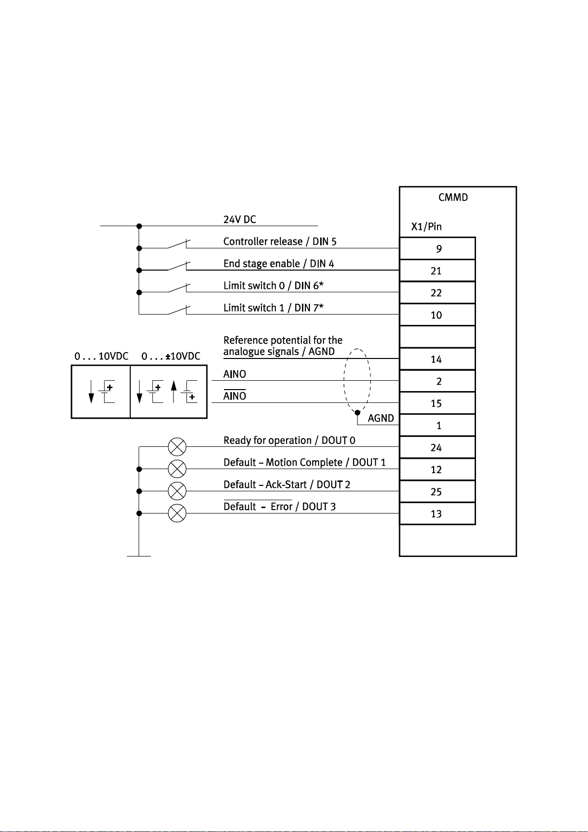
The connection plan shows the switch position in the active operating state.
*) The limit switches are set by default to opener (configuration over FCT)
3.5.2 Analogue setpoint specification
The analogue setpoint specification +/- 10V DC can be configured as
- speed setpoint value
- torque setpoint value.
Required activation with analogue setpoint specification
14533d_1
3.5.3 Interfaces for direct synchronous operation
The motor controller permits a master-slave operation, which hereafter is designated
synchronisation. The controller can function either as a master or slave.
If the motor controller works as master, it can provide (RS422) A/B signals to the
increment generator output (X10).
When the motor controller is to operate as a slave, various inputs and signal forms are
available for synchronisation.
[X10] (5 V RS422) A/B, CW/CCW, CLK/DIR
[X1] (24 V) CW/CCW, CLK/DIR)
28 Festo P.BE-CMMD-AS-HW-EN 1002NH
Page 29

3. Product description
Note
5 V DC Pulse-direction signals over [X10], max. 150 kHz
24 V DC Pulse-direction signals over [X1], max. 20 kHz
Voltage
Input
Cycle rate
5 V
[X10]
150 kHz
24 V
[X1]
up to 20 kHz
Using software, the increment generator interface can be configured as both output and
input (master or slave). Additionally, two inputs for the connection of 5V pulse-direction
signals (CLK/DIR), (CW/CCW) are planned on the plug connector.
24V DC pulse-direction signals are carried out via [X1] DIN2 and DIN3.
Output: Generation of increment generator signals [X10]
Based on the encoder data, the motor controller generates the tracking signals A/B as
well as the zero pulse of an increment generator. The number of lines can be set in the FCT
with values between 32 … 2048.
Changes to this interface only become effective after a Reset. (download, secure, reset)
An RS422 power driver provides the signals to [X10] differentially.
Input: Processing of frequency signals [X10]
The signals are evaluated optionally as A/B track signals of an increment generator or as
pulse/direction signals (CW/CCW or CLK/DIR) of a stepping motor control. The signal form
is selected in the FCT. The number of steps per revolution can be parameterized. Beyond
that, an additional electronic gear can be parameterized.
The following signals can be selected:
A/B tracking signals
CLK/DIR – pulse/direction
CW/CCW – pulse
Input: Processing of pulse-direction signals 24 V DC [X1]
CLK/DIR – pulse/direction
CW/CCW – pulse
24V DC pulse-direction signals are carried out via [X1] DIN2 and DIN3.
Clock frequency of pulse-direction signals
Table 3.2 Maximum input frequency
Festo P.BE-CMMD-AS-HW-EN 1002NH 29
Page 30

3. Product description
Note
With setting of synchronisation via FCT, the controller only reacts
via the synchronisation interface. All other functions of the
"Positioning" operating mode are no longer available.
Note
After the change of configuration with FCT with the "Download"
buttons, load the changed configurations into the motor controller
and save them permanently with the "Save" button.
With a Reset (or switching off and back on) of the motor controller,
the new configuration is activated.
Activation of synchronization
Synchronization can be set in various ways.
With the FCT parametrisation software on the "Application Data" page in
the "Operating Modes Settings" tab through selection of the "Synchronisation"
control interface
Via [X1] (digital I/O interface) through selection of mode 3.
To ensure flexibility of the controller, synchronization should be switched on over the
I/O interface.
Required I/O activation during synchronisation via FCT
- DIN4 Output stage enable
- DIN5 Controller enable
- DIN6 Limit switch 0
- DIN7 Limit switch 1
30 Festo P.BE-CMMD-AS-HW-EN 1002NH
Page 31

3. Product description
The connection plan shows the switch position in the active operating state.
*) The limit switches are set by default to N/C contact (configuration over FCT)
Required I/O triggering during synchronisation via mode switchover with 24 VDC frequency signals
14530d_1
Festo P.BE-CMMD-AS-HW-EN 1002NH 31
Page 32

3. Product description
The connection plan shows the switch position in the active operating state.
*) The limit switches are set by default to N/C contact (configuration over FCT)
Required I/O triggering during synchronisation via mode switchover with 5 VDC frequency signals
14531d_1
32 Festo P.BE-CMMD-AS-HW-EN 1002NH
Page 33

3. Product description
ENABLE
START
STOP
Drive is moving
1
0
1
0
1
0
1
0
1
0
1
0
1
0
1
0
DOUT0: READY
DOUT1: MC
DOUT3: ERROR
DOUT2:
Position synchronous
t1 t1 txtx
t
mc
0
1
DOUT2:
Setpoint reached
t1 = 1.6 ms
tx = x ms (dependent on ramps)
tmc = x ms (dependent on MC window (drive stopped))
Note
The acknowledgment of Dout2 is firmly preset to
"Position synchronous".
I/O Timing Diagram
Fig. 3.1 Signal curve during "catch up" of a leading master (MC) and during
desynchronising
The signal MC is set as long as the drive is at a standstill during active synchronisation
(DIN8: START set). That is, the MC signal is set as long as the window for "DZ = 0" has not
been left.
The signal "Position synchronous" during activation of synchronisation (DIN8: START on
high) is not set until the "Target Reached" window has been left. But since
synchronisation is switched onto a "running" master and the drive first has to be
accelerated, the "Position synchronous" message first goes off until the position
difference has been closed.
Festo P.BE-CMMD-AS-HW-EN 1002NH 33
Page 34

3. Product description
For the "Position synchronous" feedback message, the comparison speed is set to zero
and only a message range is placed in the message window.
General Information
The general limitations and settings via FCT are also valid during synchronisation (axis
movements, velocities, message window, etc.). When catching up to a leading master,
the motor accelerates to the power limit.
The message "Position synchronized" is output at Dout2. The deviation is configured
via the tolerance window for "Motion Complete" in the FCT.
3.5.4 I/O functions and device control
Digital inputs
The digital inputs provide the elementary control functions.
To allow positioning targets to be saved, the CMMD-AS motor controller has a target
table, in which positioning targets can be saved and called up later. Six digital inputs
allow you to select the targets; another input is used as the start input. Two inputs are
used to enable the hardware-side output stage and the regulator.
Digital outputs
Through the CAMC-8E8A option card, additional parametrisable outputs can be added to
the digital outputs available in the basic unit. Can be plugged into the technology slot
Ext1 and Ext2. Depending on the option card, 8 additional outputs for status signals are
available.
34 Festo P.BE-CMMD-AS-HW-EN 1002NH
Page 35

3. Product description
Mode
Function
Mode 0
Positioning
Mode 1
Jog function
Mode 2
Travel program
Mode 3
Synchronisation
Parameter
Signal level
In accordance with RS232 specification or RS485 specification
Baud rate
9600 baud to 115 kBaud
ESD protection
ESD-protected (16 kV) driver
Connection
Null modem standard [X5]
Connector socket
over [X5] / D-Sub 9 pin / pin
Limit switch
The limit switches serve to limit the range of motion for safety reasons. During homing,
one of the two limit switches can serve as reference points for positioning control.
Sample input
If a fieldbus is used for activation, a high-speed sampling input is available for time-critical
tasks for various applications (position sensing, special applications, ...).
Analogue input
The CMMD-AS motor controller has an analogue input for input levels ranging from
+10 VDC to –10 VDC. The input is a differential input (12 bit), ensuring a high degree of
protection against interference. The analogue signals are quantified and digitalised by
the analogue-digital converter at a resolution of 12 bits. These analogue signals serve to
specify setpoints (speed or torque) for the control.
Basic functions
The existing digital inputs are already allocated to the basic functions in standard
applications. The analogue input AIN0 is also available as a digital input for use of further
functions, such as the jog function, route program and synchronisation.
Mode switching allows you to switch between the following default settings:
Table 3.3 Mode switching
3.5.5 RS232 interface (diagnosis/ parametrisation interface)
The RS232 interface is intended as a configuration interface.
Table 3.4 Parameters of the RS232 interface
Festo P.BE-CMMD-AS-HW-EN 1002NH 35
Page 36

3. Product description
Parameter
Value
Baud rate
9600 Baud
Data bits
8
Parity
None
Stop bits
1
Parameter
Value
Flow control
None
Emulation
VT100
ASCII configuration
- Sent characters finish with line feed
- Output entered characters locally (local echo)
- During reception, attach line feed to the end of the line
Command
Syntax
Response
New initialisation of the servo positioning controller
RESET!
None (bootup message)
Save the current parameter set and all position sets in the
non-volatile flash memory.
SAVE!
DONE
Setting the baud rate for serial communication
BAUD9600
BAUD19200
BAUD38400
BAUD57600
BAUD115200
Unknown command
as desired
ERROR!
Read the version number of the CM (Configuration
Management) release of the firmware
VERSION?
2300:VERSION:MMMM.SSSS*)
*)MMMM: Main version of the CM release (hexadecimal format)
SSSS: Subversion of the CM release (hexadecimal format)
After reset, the serial interface always has the following basic settings:
Table 3.5 Default parameter
To be able to operate an interface with a terminal program, such as for test purposes, the
following settings are required (recommendations):
Table 3.6 Setting for terminal program
Please note that, immediately after a reset, the motor controller independently issues a
bootup message via the serial interface. A reception program on the controller must either
process or reject these received characters.
General commands
Table 3.7 General commands
36 Festo P.BE-CMMD-AS-HW-EN 1002NH
Page 37

3. Product description
Note
To address the communication objects (CO) of axis 2, the character
# is set before the syntax command.
Answers of axis 2 begin with the character #.
The same applies for simulated CAN accesses.
Command
Syntax
Response
Reading a CO
OR:nnnn
nnnn:HHHHHHHH or OR:EEEEEEEE
Writing a CO
OW:nnnn:HHHHHHHH
OK! or OW:EEEEEEEE
Reading a lower limit of a CO
ON:nnnn
nnnn:HHHHHHHH or ON:EEEEEEEE
Reading an upper limit of a CO
OX:nnnn
nnnn:HHHHHHHH or OX:EEEEEEEE
Reading an actual value of a CO
OI:nnnn
nnnn:HHHHHHHH or OI:EEEEEEEE
*)nnnn: Number of the communication object (CO), 16 bit (hexadecimal format)
HHHHHHHH: 32 bit data / values (hexadecimal format)
EEEEEEEE: Return value in case of an access fault
Return value
Significance
0x0000 0002
Data are less than the lower limit, data were not written
0x0000 0003
Data are greater than the upper limit, data were not written
0x0000 0004
Data are less than the lower limit, the data were limited to the lower limit
and then accepted
0x0000 0005
Data are greater than the upper limit, the data were limited to the upper limit
and then accepted
0x0000 0008
Data are outside the valid value range and were not written
0x0000 0009
Data are currently outside the valid value range and were not written
Parameter commands
The exchange of parameters and data takes place over "communication objects" (CO).
They are used in a fixed syntax. Special return values are defined for errors in a write or
read access.
Examples
Acknowledge error axis 1 OW:0030:0001 0000 Answer: OK!
Acknowledge error axis 2 #OW 0030:0001 0000 Answer: #OK!
Homing mode axis 1 Command: =606000:06
Homing mode axis 2 Command: #=606000:06
Table 3.8 Parameter commands
The meaning of the return values is the following:
Table 3.9 Return values
Festo P.BE-CMMD-AS-HW-EN 1002NH 37
Page 38

3. Product description
Command
Syntax
Response
Activate controller enable. To do this, the controller
enable logic must be set to "DIN5 and RS232".
OW:0061:00000001
OK! or OW:EEEEEEEE
1)
Deactivate controller enable. To do this, the controller
enable logic must be set to "DIN5 and RS232".
OW:0061:00000002
OK! or OW:EEEEEEEE1)
Deactivate end stage. To do this, the controller enable
logic must be set to "DIN5 and RS232".
OW:0061:00000003
OK! or OW:EEEEEEEE1)
Acknowledge error
OW:0030:00010000
OK!
1) Faulty return values can be called up due to an inappropriately set controller enable logic,
an intermediate circuit that is not loaded, etc.
Operating mode
Syntax
Response
Regulating torque
OW:0030:00000004
OK! or OW:EEEEEEEE
Speed control
OW:0030:00000008
Positioning
OW:0030:00000002
Note
If you want to perform a positioning, a homing must be performed
once each time the controller is switched on. You can do this via
FCT or as described in chapter "Example "Homing Mode" via
RS232".
Function commands
Table 3.10 Function commands
Setting the operating mode
Due to a necessary synchronization of internal processes, the change of operation mode
can require some cycle times of the controller. We therefore recommend that you always
verify and wait for reception of the desired operation mode.
Table 3.11 Operating mode
Faulty return values can be called up due to invalid values that do not come from the
above-named group. The current operation mode can be read by using the "OR"
command.
Example "Profile position mode" via RS232
With the CAN access simulated via RS232, the motor controller can also be operated in the
CAN "Profile Position Mode". The following describes the sequence in principle.
1. Conversion of the controller enable logic
The controller enable logic can be converted via the COB 6510_10. Since the
simulation of the CAN interface over RS232 can be completely taken over, the enable
logic can also be converted to DINs + CAN.
Command: =651010:0002
As a result, the release can be granted via the CAN control word (COB 60040_00).
Command: =604000:0006 Command "Shutdown"
Command: =604000:0007 Command "Switch on / Disable Operation"
Command: =604000:000F Command "Enable Operation"
38 Festo P.BE-CMMD-AS-HW-EN 1002NH
Page 39

3. Product description
2. Activation of the "Profile Position Mode"
The positioning mode is activated via the COB 6060_00 (Mode of Operation). This
must be written once, since all internal sectors must be set correctly thereby.
Command: =606000:01 Profile Position Mode
3. Write position parameters
The target position can be written over the COB 607A_00 (target position). The
target position is thereby written in "position units". That means, it depends on the
set CAN factor group.
The default setting here is 1 / 2
16
revolutions (16 bit portion before the decimal, 16
bit portion after the decimal).
Command: =607A00:00058000 Target position 5.5 revolutions
The travel speed can be written via the COB 6081_00 (profile velocity),
the final speed via the COB 6082_00 (end velocity).
The speeds are thereby written in "speed units". That means, they depend on the
set CAN factor group.
The default setting here is 1 / 2
12
revolutions/min (20 bit portion before the decimal,
12 bit portion after the decimal).
Command: =608100:03E80000 Speed of travel 1000 RPM
The acceleration can be written via the COB 6083_00 (profile acceleration),
the deceleration via the COB 6084_00 (profile deceleration) and
the quick stop ramp via the COB 6085 (quick stop deceleration).
The accelerations are thereby written in "acceleration units". That means, they
depend on the set CAN factor group.
The default setting here is 1 / 28 revolutions/min/s (24 bit portion before the
decimal, 8 bit portion after the decimal).
Command: =608300:00138800 Acceleration 5000 RPM/s
4. Start positioning
Positioning is started via the CAN control word (COB 6040_00):
- Controller enable is controlled via bit 0 ... 3 (see above).
- The positioning is started over a rising edge at bit 4.
The following settings are taken over thereby.
- Bit 5 establishes whether an ongoing positioning is ended first before the
new positioning task is taken over (0), or whether the ongoing positioning
should be cancelled (1)
- Bit 6 establishes whether the positioning should be carried out absolutely (0)
or relatively (1).
Command: =604000:001F Start absolute positioning or
Command: =604000:005F Start relative positioning
5. After positioning has been ended, the condition of the controller is reset so a new
positioning can be started.
Command: =604000:000F Bring motor controller into "Ready" status
Festo P.BE-CMMD-AS-HW-EN 1002NH 39
Page 40

3. Product description
Example "Homing Mode" via RS232
With the CAN access simulated via RS232, the CMMD-AS can also be operated in the CAN
"Homing Mode". The following describes the sequence in principle.
1. Changing of the controller enable logic
2. The controller enable logic can be converted via the COB 6010_10. Since the
simulation of the CAN interface over RS232 can be completely taken over, the enable
logic can also be converted to DINs + CAN.
Command: =651010:0002
3. As a result, the release can be granted via the CAN control word (COB 6040_00).
Command: =604000:0006 Command "Shutdown"
Command: =604000:0007 Command "Switch on / Disable Operation"
Command: =604000:000F Command “Enable Operation”
4. Activation of the "Homing mode"
5. The homing mode is activated via the COB 6060_00 (Mode of Operation).
Command: =606000:06 Homing mode
6. Start reference travel
7. Homing is started via the CAN control word (COB 6040_00):
8. Controller enable is controlled via bit 0 ... 3.
9. The homing is started via a rising edge at bit 4.
Command: =604000:001F
10. After homing has been ended, the status of the motor controller must be reset.
Command: =604000:000F Bring motor controller into "Ready" status
3.5.6 Control via RS485
The RS485 interface is on the same plug connector as the RS232 interface.
Communication must be activated separately by the user. RS232 messages can also be
received when RS485 communication is activated, which means that the device can be
accessed for configuration at all times.
Configuration in the FCT
For configuration, the following settings are required in the "Work station" window:
- On the "Application Data" page in the "Operating Mode Settings" tab, set the
control interface to "RS485".
- On the page "Controller, Control Interface, Digital I/O", do not activate the
"active" mode selection
40 Festo P.BE-CMMD-AS-HW-EN 1002NH
Page 41

3. Product description
Note
The reply sends the following characters to the first five
positions: "XRnn:" with nn = node number of the device
All devices react to the node number 00 as "Broadcast". In this
way, each device can be addressed without knowing the node
number.
The commands of type "OW", "OR" etc. support an optional
check sum. This check sum is formed without the first five
characters.
The bootup message of the boot loader as well as the bootup
message of the firmware are sent in the RS232 mode.
Then, with the "Download" buttons, load the changed configurations into the motor
controller and save them permanently with the "Save" button.
With a Reset (or switching off and back on) of the motor controller, the new configuration
is activated.
Command syntax under RS485
Control of the motor controller via RS485 takes place with the same objects as with
RS232. Only the syntax of the commands to read/write the objects is expanded in
comparison to the RS232.
Syntax: XTnn:HH……HH:CC
Meanings:
XT: Fixed constants
nn: Node number, identical to the CANopen node number
(setting via DIP switch)
HH……HH: Data (normal command syntax)
Example "Profile position mode" via RS232
If the CMMD-AS is operated over RS485, control can take place just as with
operation over RS232; see chapter "RS232 interface (diagnosis/ parametrisation
interface)" (page 35). If required, the node number is simply written in front of the
command. The node number is set via the DIP switches.
Command: XT07:=607100:000A0000 Target position 10 revolutions send to
node 7
Festo P.BE-CMMD-AS-HW-EN 1002NH 41
Page 42

3. Product description
Parameter
Value
Communication protocol
Heidenhain EnDat 2.1 (without analogue track) and 2.2
Signal level DATA, SCLK
5 V differential / RS422 / RS485
Angle resolution /
number of lines increment
generator
controller-internal up to 16 bit / revolution
Cable length
L 25 m
Cable design in accordance with Heidenhain specification
Limit frequency SCLK
1 MHz
Generator supply
from the controller, 5 V –0% / +5%
IA = 200 mA max.
Sense lines for power supply
not supported
The second axis gets the address of the first axis +1
Node number
= node number
Slave
Master
+1
3.5.7 Multi-firmware strategy
A firmware update can be achieved using any desired customer firmware through the
built-in SD card reader. Automatic bootloader.
3.5.8 Motor feedback
Position return takes place purely digitally via EnDat.
EnDat interface V2.x for single and multiturn encoders
Table 3.12 Signal description of shaft encoder motor EnDat 2.1 and 2.2 [X2]
3.5.9 Brake chopper (Brake control)
A brake chopper with a braking resistor is integrated into the output stage. If the
permitted load capacity of the intermediate circuit is exceeded during the energy
recovery, the braking energy may be converted to heat by the internal braking resistor.
The brake chopper is actuated with software control. The internal braking resistor is
protected against overloading via software and hardware.
3.5.10 Feedback from motor (angle encoder)
The CMMD-AS has a connection for an angle encoder mounted on the motor shaft. This
encoder is used for commutation of a 3-phase synchronous motor and as an actual-value
recorder for the built-in speed and position controller.
The controller supports the following encoders:
EnDat 2.1 encoder – exclusively digital angle information
EnDat 2.2 encoder – digital angle information and service parameters (temperature)
42 Festo P.BE-CMMD-AS-HW-EN 1002NH
Page 43

3. Product description
Signal:
Description
AMON
AIN0 / #AIN0
Analogue output for monitor purposes
Differential analogue input with 12-bit resolution.
Alternatively, the differential analogue input can be parameterized with the function
Mode and Stop (DIN12 and DIN13, dependent on the parametrised controller interface).
DOUT0 ... DOUT3
Digital outputs with 24 V level,
DOUT0 is permanently occupied with the function "Ready for operation".
Additional outputs can be configured (Motion complete (Target Reached), Axis in
motion, Target speed achieved, ...)
DIN0 ... DIN13
Digital inputs for 24 V level with following functions:
(The inputs are occupied in their function, dependent on the mode selection)
Mode 0
1 x output stage enable (DIN4)
1 x controller enable / acknowledge error (DIN5)
2 x limit switch (DIN6, DIN7)
6 x position selection (DIN0 ... DIN3, DIN10, DIN11)
1 x start positioning (DIN8)
2 x mode shift (DIN9, DIN12)
1 x stop (DIN13)
Mode 1
2 x jog mode (DIN10, DIN11)
1 x teach (DIN8)
Mode 2
1 x halt route program (DIN3)
1 x start route program (DIN8)
2 x next for route program step enabling condition (DIN 2, 11)
Mode 3
2 x pulse/direction (CLK/DIR or CW/CCW on DIN2, DIN3)
1 x start sync (DIN8)
3.5.11 Control interface [X1]
The control interface [X1] is planned as D-Sub 25-pin. The following signals are available:
Table 3.13 Control interface [X1]
The digital inputs are designed to be configurable:
Mode 0: Standard assignment
Mode 1: Special assignment for jog/teach operation
Mode 2: Special assignment for the route program
Mode 3: Special assignment for synchronisation
To be able to switch between different I/O configurations, DIN12 and DIN9 can also be
configured as selector signals.
As a result, a maximum of four different I/O assignments can be selected. These are
described in the following tables:
Table 6.2 Pin allocation: I/O interface [X1] mode 0
Table 6.3 Pin allocation: I/O interface [X1] mode 1
Table 6.4 Pin allocation: I/O interface [X1] mode 2
Table 6.5 Pin allocation: I/O interface [X1] mode 3.
Festo P.BE-CMMD-AS-HW-EN 1002NH 43
Page 44

3. Product description
Note
When a parameter set is loaded from the memory card, the newest
parameter set is always loaded.
3.5.12 Increment generator interface [X10]
Using software, the increment generator interface can be configured both as input and as
output. Additionally, two inputs for the connection of 5V pulse-direction signals (CLK/DIR,
CW/CCW) are planned on the plug connector.
Encoder emulation of the increment generator – [X10] is output:
From the rotational angle determined via the encoder at the motor, the controller
generates the track signals A and B as well as the zero pulse of an increment generator.
The signals A, B, and N equal those of an increment generator.
Angle resolution / Number of lines Output
The number of lines is continuously switchable.
The following numbers of lines are supported: 2048 – 32 lines per revolution.
The switch only becomes effective after a Reset of the controller. An RS422 power driver
provides the signals to [X10] differentially.
Synchronisation – [X10] is input
Using software, the [X10] interface can be configured as an input for processing of
incremental encoder or pulse-direction signals.
The signals are evaluated optionally as A/B track signals of an increment generator or as
pulse/direction signals (CW/CCW, CLK/DIR) of a stepping motor control. The signal form is
selected via software. The number of steps per revolution can be parametrised. Beyond
that, an additional electronic gear can be parameterized.
3.5.13 SD card holder [M1]
To permit saving of control parameters as well as the complete controller firmware,
a connection possibility for an SD memory card (popular storage medium for digital
cameras) has been incorporated. The connection has been designed as a "push-push"
holder for reasons of quality perception.
3.5.14 SD memory card
Via the SD memory card, parameter sets can be loaded or firmware can be downloaded.
A menu in the parametrisation software allows you to specify a set of parameters on the
memory card and load it or save it.
Also, a configuration word in the parameter record can be used to specify whether
firmware and/or a parameter record is to be loaded from the memory card automatically
on activation.
44 Festo P.BE-CMMD-AS-HW-EN 1002NH
Page 45

3. Product description
If automatic firmware download (dip switch 8 = 1) is activated or there is no valid firmware
in the controller, a check is performed on initialisation whether an SD memory card is
inserted, and if so, it is initialised. If there is a firmware file on the card, it is checked first
(checksum test). If no fault is found, the firmware is transferred from the card to the
controller and saved in the FLASH program.
If the automatic loading of the parameter set is activated via the commissioning software,
the system checks whether a card is inserted when the firmware is started and it is
initialised if applicable. Depending on the setting, a specific or the latest parameter record
file is loaded and saved in the data flash.
In the CMMD-AS, the interface [M1] is only executed for the master. The master reads the
data from the SD card and passes it on to the slave via the SSIO.
A special case is loading of firmware from the SD card after Power ON: After Power ON,
the master at first holds the slave in Reset. The master first loads its firmware from the SD
card. With the start of the application, the RESET pilot line for the slave is switched
inactive. Now the slave takes over the "master" function on the SSIO interface and
directly accesses the SD card to load the same firmware from the SD card.
Only after completion of the firmware download is the cyclical and synchronous SSIO
communication established between master and slave.
3.6 Field bus interface
With the CMMD-AS, different fieldbusses can be used. By default, the CAN bus is
permanently integrated into the motor controller with the CMMD-AS. Optionally, the
PROFIBUS or DeviceNet can be used via plug-in modules. But only one field bus can
ever be active for both axes at the same time. Card modules may only be mounted in
the slot [Ext 1].
For all field busses, the Festo Profile for Handling and Positioning (FHPP) has been
implemented as the communication protocol. Additionally, for the CAN bus, the
communication protocol based on the CANopen profile in accordance with the CiA Draft
Standard DS-301 and the drive profile in accordance with the CiA Draft Standard DSP-402
have been implemented.
Independent of the fieldbus, a factor group can be used so that application data can be
transferred into user-specific units.
Festo P.BE-CMMD-AS-HW-EN 1002NH 45
Page 46

3. Product description
The connection plan shows the switch position in the active operating state.
*) The limit switches are set by default to N/C contact (configuration over FCT)
Required I/O connection for field bus control
14534d_1
3.6.1 FHPP (Festo Handling and Positioning Profile)
FHPP makes it possible to achieve a uniform control concept regardless of the fieldbus
used. The user therefore no longer has to be concerned with the specific characteristics of
the respective busses or controllers (PLC), but receives a preparametrised profile in order
to place his drive into operation in the shortest possible time and control it.
Among the operation types, FHPP distinguishes between record selection and direct
operation.
With record selection, the position records stored in the motor controller are used.
In direct operation, the following operating modes are possible:
Positioning mode
Speed control
Force control.
The operating modes can be dynamically switched over in direct operation as needed.
Additional information can be found in the FHPP manual P.BE−CMM−FHPP−SW−DE.
46 Festo P.BE-CMMD-AS-HW-EN 1002NH
Page 47

3. Product description
3.6.2 CAN bus
The CAN bus is permanently integrated into the motor controller and can be parametrised
and activated/deactivated via the DIP switches on the front side. With the DIP switches,
the node address and baud rate can be set visibly from the outside.
The second axis gets the address of the first axis +1
Node number
In addition, a termination resistor can be connected and the CAN bus switched on or off.
The motor controller supports baud rates up to 1Mbit/s.
If the communication protocol FHPP is used, the operating modes mentioned in chapter 0
are available.
Alternatively, if the CANopen protocol in accordance with DS301 with application profile
DSP402 is activated, the following operating modes can be used:
Positioning mode (CiA: (profile position mode)
Homing mode (CiA: homing mode)
Interpolating position mode (CiA: interpolated position mode)
Speed control (CiA: profile velocity mode)
Force mode (CiA: torque profile mode).
Communication can take place optionally over SDOs (service data objects) and/or PDOs
(process data objects). Two PDOs are available for each sending direction
(transmit/receive).
= node number
Slave
Master
+1
Path control with linear interpolation
With the "interpolated position mode", a path control can be implemented in a multi-axis
application of the controller. For this, position setpoints are specified by a higher-order
control system in a fixed time slot pattern. If the time slot pattern of the position setpoints
is greater than the internal position controller cycle time of the motor controller, the
controller automatically interpolates the data values between two prescribed position
setpoints. The motor controller also calculates a corresponding speed pilot control.
Festo P.BE-CMMD-AS-HW-EN 1002NH 47
Page 48

3. Product description
1 Position
setpoint time
slot pattern
2 Position
control cycle
time
3 Interpolated
sequence of
the position
4 Interpolated
sequence of
the position
4711d_21
1 2 3
4
Fig. 3.2 Interpolated Position Mode
3.6.3 PROFIBUS
The motor controller is connected to the PROFIBUS with a corresponding extension
module (CAMC-PB), which can be plugged into the extension slot [Ext 1] . If the module is
plugged in, it is automatically activated the next time the motor controller is switched on.
The slave address is configured over the Dip switches on the front side of the motor
controller.
For the PROFIBUS, only the bus address specified on the Dip switches is assigned.
The data for the two controllers is sent in a shared telegram.
Baud rates up to 12 MBaud are supported.
FHPP is used as communication protocol with the control and operating modes described
in chapter 3.6.1.
3.6.4 DeviceNet
The motor controller is connected to the DeviceNet network with a corresponding
extension module (CAMC-DN), which can be plugged into the extension slot [Ext 1] . If the
module is plugged in, it is automatically activated the next time the motor controller is
switched on.
The MAC-ID and baud rate are configured over the DIP switches on the front side of the
controller.
In a DeviceNet network, only the bus address specified on the DIP switches is assigned.
The data for the two controllers is sent in a shared telegram.
Baud rates up to 500 kBaud are supported.
FHPP is used as communication protocol with the control and operating modes described
in chapter 3.6.1.
48 Festo P.BE-CMMD-AS-HW-EN 1002NH
Page 49

3. Product description
Operating mode
Function
(Setpoint value) interface
Setpoint specification via
Regulating torque
–
Analogue setpoint
[X1]
Fieldbus
Direct mode
Speed control
–
Analogue
[X1]
CW/CCW signals
[X1] (24 V / mode 3)
[X10] (5 V)
CLK/DIR
pulse/direction signals
[X1] (24 V / mode 3)
[X10] (5 V)
Fieldbus
Direct mode
Master/Slave
A/B signals +
I/O (start synchronization)
[X10]
[X1] (mode 3)
Position control
(CAN DS402)
–
Fieldbus
Interpolated Position Mode
Fieldbus
Direct mode
Positioning controller
–
I/O
Record selection
Fieldbus
Direct mode
Fieldbus
Record selection
Homing
I/O
Record selection
Fieldbus
Direct mode
Fieldbus
Record selection
Jog mode
I/O – Fieldbus
Direct mode
Teach-in function
via I/O
–
3.7 Function overview
3.7.1 Operating modes
- Setpoint specification via increment generator signals, suitable for frequencies
up to 150 kHz
- Analogue speed specification with 12-bit resolution
- Reference point
- Simple connection via digital inputs and outputs to a higher-order controller,
e.g. a PLC.
- Jolt-limited or time-optimised positioning absolutely or relative to a reference
point via the integrated trajectory generator.
- Position specification via the integrated fieldbus CANopen with automatic
interpolation between the setpoints
Table 3.14 Operating modes
Festo P.BE-CMMD-AS-HW-EN 1002NH 49
Page 50

3. Product description
ENABLE
STOP
DIN12
1
0
1
0
1
0
1
0
0
1
0
1
0
1
0
1
0
DIN9
1
0
1
DOUT0: READY
DOUT1: MC
DOUT2: ACK
DOUT3: ERROR
21 1 3 4 1
t1 t1 t1 t1 t1
t1 = 1.6 ms
1) Positioning
2) Sequences / Route program
3) Jog / Teach
4) Synchronisation
Timing diagram, operating mode shift
Fig. 3.3 Timing for activation of the individual operating modes
3.7.2 Setpoint value processing
Setpoint value selectors allow you to switch setpoint values from various sources to the
corresponding controllers. The following setpoint value selectors are implemented in the
firmware:
- Selector for the speed setpoint
- Auxiliary value selector whose setpoint value is added to the speed setpoint.
The position of the setpoint value selectors is saved in non-volatile parameters.
Depending on the prefix, the speed setpoint is disabled via the signal of the
corresponding limit switch input. The limit switch inputs also affect the ramp generator for
the speed setpoint.
The speed setpoint (without the auxiliary setpoint) is reached via a setpoint ramp. It
permits setting various accelerations and brake decelerations in both directions so the
resulting setpoint value process can be adjusted to the path dynamics of motor and load.
The setpoint ramp can be deactivated.
50 Festo P.BE-CMMD-AS-HW-EN 1002NH
Page 51

3. Product description
3.7.3 I²t function
An integrator monitors the current²-time integral of the motor controller. As soon as the
parameterized time is exceeded, a warning message is output and the maximum current is
limited to the rated current.
3.7.4 Positioning controller
A positioning control system is set above the current controller. Up to 64 positions
(homing + 63 positions) can be selected per axis and run via a trajectory generator.
There are also volatile position data records for positioning via the fieldbus.
The position records are made up of a position value and a motion profile. The following
parameters can be set for the eight positioning profiles:
- Travel speed
- Acceleration
- Delay
- Smoothing
- Time
- Start delay
- Final speed
- Wait for current positioning, reject or ignore initial instruction.
From every position record, any other position record can be started directly. You can
transition to a new position record without first coming to a standstill.
The parameter sets can be called up as follows:
- over digital inputs (position record 0 ... 63 per axis)
- over the RS232 interface (for test purposes only) or
- over a fieldbus interface.
Festo P.BE-CMMD-AS-HW-EN 1002NH 51
Page 52

3. Product description
The connection plan shows the switch position in the active operating state.
*) The limit switches are set by default to N/C contact (configuration over FCT)
Required I/O interface for positioning
14532d_1
52 Festo P.BE-CMMD-AS-HW-EN 1002NH
Page 53

3. Product description
Run to
Positive
method
Negative
method
Graphical representation
Dec
Hex
Dec
Hex
Limit switch with zero pulse
evaluation
2
02 1 01
Negativer
Endschalter
Index Impuls
1
Fixed stop with zero pulse
evaluation
–2
FE
–1
FF
Index Impuls
-1
Limit switch
18
12
17
11
Fixed stop
–18
EE
–17
EF
-17
Zero pulse
34
22
33
21
Save current position
35
23
35
23
Method
1
Negative proximity switch with index pulse.
If negative limit switch inactive:
Run at search speed in negative direction to the negative limit switch.
Run at crawl speed in positive direction until the limit switch becomes inactive,
then on to first index pulse. This position is saved as a reference point.
If configured: Run at travel speed to axis zero point.
3.7.5 Homing
You can choose either of the following methods which are based on DS402.
Table 3.15 Methods of homing
Festo P.BE-CMMD-AS-HW-EN 1002NH 53
Page 54

3. Product description
Method
2
Positive limit switch with index pulse.
1. If positive limit switch inactive:
Run at search speed in positive direction to the positive limit switch.
Run at crawl speed in negative direction until the limit switch becomes inactive,
then on to first index pulse. This position is saved as a reference point.
If configured: Run at travel speed to axis zero point.
–1
Negative stop with index pulse 1)
2. Run at search speed in negative direction to stop.
Run at crawl speed in positive direction to next index pulse. This position is saved
as a reference point.
If configured: Run at travel speed to axis zero point.
–2
Positive stop with index pulse 1)
3. Run at search speed in positive direction to stop.
Run at crawl speed in negative direction to next index pulse. This position is saved
as a reference point.
If configured: Run at travel speed to axis zero point.
17
Negative limit switch
4. If negative limit switch inactive:
Run at search speed in negative direction to the negative limit switch.
Run at crawl speed in positive direction until limit switch becomes inactive.
This position is saved as a reference point.
If configured: Run at travel speed to axis zero point.
18
Positive limit switch
5. If positive limit switch inactive:
Run at search speed in positive direction to the positive limit switch.
Run at crawl speed in negative direction until limit switch becomes inactive.
This position is saved as a reference point.
If configured: Run at travel speed to axis zero point.
–17
Negative stop
1)2)
6. Run at search speed in negative direction to stop. This position is saved
as a reference point.
If configured: Run at travel speed to axis zero point.
–18
Positive stop
1)2)
7. Run at search speed in positive direction to stop. This position is saved
as a reference point.
If configured: Run at travel speed to axis zero point.
33
Index pulse in a negative direction
8. Run at crawl speed in negative direction to index pulse. This position is saved
as a reference point.
If configured: Run at travel speed to axis zero point.
34
Index pulse in a negative direction
9. Run at crawl speed in positive direction to index pulse. This position is saved
as a reference point.
If configured: Run at travel speed to axis zero point.
35
Current position
10. The current position is saved as the reference point.
If configured: Run at travel speed to axis zero point.
Note: If the reference system is shifted, runs to the limit switch or fixed stop are possible.
The are therefore generally used for rotating axes.
Table 3.16 Explanation of the homing methods
54 Festo P.BE-CMMD-AS-HW-EN 1002NH
Page 55

3. Product description
Controller
release
START
1
0
1
0
1
0
1
0
1
0
1
0
1
0
Limit switch E0
1
0
DOUT0: READY
DOUT1: MC
DOUT2: ACK
DOUT3: ERROR
Statusword
referenced
1
Limit switch E1
0
1
0
– +
t1 t1 tx tx txtx
0
1
STOP
t1 = 1.6 ms
tx = x ms (dependent on ramps)
Timing diagram for homing
Fig. 3.4 Signal sequence with start of the homing run and with positive design
Festo P.BE-CMMD-AS-HW-EN 1002NH 55
Page 56

3. Product description
Controller
release
START
1
0
1
0
1
0
1
0
1
0
1
0
1
0
Limit switch E0
1
0
DOUT0: READY
DOUT1: MC
DOUT2: ACK
DOUT3: ERROR
Statusword
referenced
1
Limit switch E1
0
Drive is moving
1
0
neg pos
t1 t1 tx txtx tx
1
0
STOP
t1 = 1.6 ms
tx = x ms (dependent on ramps)
Fig. 3.5 Signal sequence with faulty interruption (contour error, ...)
56 Festo P.BE-CMMD-AS-HW-EN 1002NH
Page 57

3. Product description
Controller
release
START
1
0
1
0
1
0
1
0
1
0
1
0
1
0
Limit switch E0
1
0
DOUT0: READY
DOUT1: MC
DOUT2: ACK
DOUT3: ERROR
Statusword
referenced
1
Limit switch E1
0
1
0
– +
STOP
1
0
t1 t1 t1tx txtx tx
Drive is moving
t1 = 1.6 ms
tx = x ms (dependent on ramps)
Fig. 3.6 Signal curve with abort through STOP input
3.7.6 Trajectory generator
With a start signal for a positioning set via DIN8, field bus or RS232
interface, the selected positioning set is loaded into the trajectory generator.
Based on the data record loaded, the necessary internal pre-calculations are made.
The pre-calculations can take from 1.6 to 5 ms. The following configurable options are
available for processing the start signal.
- A start signal detected during an ongoing positioning run is ignored (ignoring).
- After a start signal is detected during an ongoing positioning run, the run
continues to the end (waiting).
- After a start signal is detected, positioning is cancelled and the drive runs
at a constant speed. After pre-calculation is completed, the drive runs to the
new target position (interrupting).
The trajectory generator sends the following messages:
- Target reached, (Default: digital output DOUT1 – MC)
- Remaining distance reached.
Festo P.BE-CMMD-AS-HW-EN 1002NH 57
Page 58

3. Product description
T25
T24
T23
T20
T21
T18
T19
T17
T16
T15
T13
T12
T10
T11
T9
T8
T6
T5
T4
T3
T2
T1
RESET
Power ON
Boot program
Firmware
download
Initialisation
Ready for
operation
Initialise SD card
Load save SD card
parameters
From all except
RESET / Power ON
Error condition
Acknowledge error
Activate
output stage
Regulating torque
Speed control
Positioning controller
Jog
mode
Homing
3.7.7 I/O sequence control
58 Festo P.BE-CMMD-AS-HW-EN 1002NH
Page 59

3. Product description
T
Transition condition
Actions of the user
T1
RESET / Power ON
–
T2
Time out has expired or the firmware download is
complete.
–
T3
The initialisation has been carried out successfully.
–
T4 DIN4=1 and DIN5=1
T5
"Torque control" was selected in the commissioning
software.
Setpoint specification via AIN0/AGND
T6
"Speed control" was selected in the commissioning
software.
Setpoint specification via AIN0/AGND
T8
"Positioning" was selected in the commissioning
software.
Set selection via
DIN0 … DIN3, DIN10, DIN11
Start for the positioning process:
DIN8=1
T9
All parameters for the jog mode were set in the
commissioning software
(e.g. max. speed, acceleration ...).
Selection I/O mode:
DIN9=0, DIN12=1
Jog +: DIN10=1
Jog –: DIN11=1
T10 – Selection I/O mode:
DIN9=0, DIN12=1
T11
Selection of the homing method and parametrisation of
the speeds and accelerations in the commissioning
software.
Selection I/O mode: 0
DIN9=0, DIN12=0
Selection of positioning record 0
Start for positioning process:
DIN8=1
T12
Drive is referenced.
–
T13 – DIN5=0
T15 – DIN5=0
T16 – DIN5=0
T17 – DIN4=0
T18 – Write or read request to SD card such
as:
Load parameters
- Save parameters
- Firmware download.
T19
The SD card was initialised successfully.
–
T20
"Load from SD after restart" was selected in the
commissioning software.
–
T21
Parameter record was loaded.
–
T22
A fault has occurred which causes the end stage to be
switched off
–
T23 – –
T24 – Edge controlled fault acknowledgement
DIN5: 1 – 0
T25
The error was acknowledged and no other errors are
pending.
–
Table 3.17 I/O sequence control
Festo P.BE-CMMD-AS-HW-EN 1002NH 59
Page 60

3. Product description
Controller
enable
Drive is moving
0
1
0
1
0
1
0
1
0
Holding brake
Current-carrying
1
DOUT0: READY
Output stage
release
1
0
tyt1 tx
Motor controlled
t1 = 1.6 ms
tx = x ms (dependent on brake ramps)
ty = x ms (dependent on set switch-off delay)
3.7.8 Safety functions, error messages
The following statuses are monitored for safe operation of the CMMD-AS:
- Safe halt, EN ISO 13849/Cat 3 and IEC 61508
- Final stage temperature
- Motor temperature
- Intermediate circuit voltage to minimum and maximum value
- Initialization fault
- Check-sum error on parameter transmission
- Communications errors
- Following error
- Homing
- Overload current/short circuit in the power end stage
- Encoder system
- Watchdog (processor monitoring).
3.7.9 Behaviour when switching off enable
Fig. 3.7 Behaviour when switching off controller enable
60 Festo P.BE-CMMD-AS-HW-EN 1002NH
Page 61

3. Product description
Controller
released
Drive is moving
0
1
0
1
0
1
0
1
0
Holding brake
current-carrying
1
DOUT0: READY
Output stage
release
1
Motor controlled
0
tyt1
t1 = 1.6 ms
tx = x ms (dependent on brake ramps)
Note
The holding brake of the EMMS-AS-…- is not suitable for braking
the motor.
Fig. 3.8 Behaviour when switching off end-stage enable
Festo P.BE-CMMD-AS-HW-EN 1002NH 61
Page 62

3. Product description
Controller
release
START
Intermedicate circuit
1
0
1
0
1
0
1
0
1
0
1
0
1
0
1
0
Holding brake
currentcarrying
1
0
DOUT0: READY
DOUT1: MC
DOUT2: ACK
DOUT3: ERROR
Output stage
release
1
Output stage
switched on 0
Drive is moving
1
0
t1 t1 tx t1
t1 = 1.6 ms
tx = x ms (ZK discharges)
Note
The holding brake of the EMMS-AS-…- is not suitable for braking
the motor.
off immediately)
Fig. 3.9 Behaviour during interruption of the intermediate circuit supply (error: end stage
3.7.10 Oscilloscope function
The oscilloscope function implemented in the firmware of the controller is an important
aid to help the commissioning party to optimise the controller settings without using
a separate measuring device. The function allows important signal sequences to be
recorded over time. It consists of three blocks:
62 Festo P.BE-CMMD-AS-HW-EN 1002NH
- The initialisation section which runs at low priority and performs pre-
calculations for the actual measurement process.
- The data transfer section also has low priority. It is integrated into the time slice
of the serial communication.
- The measuring section runs at a high priority in the rule interrupt and records
the measuring channels. If the trigger condition occurs, the measurement
process is cancelled after a defined number of scan steps.
Page 63

3. Product description
Note
Make sure that the taught positions are written in the permanent
memory before the controller is switched off.. Incorrect storing can
make the parameter file invalid.
Note
The positions are saved on the SD card only through FCT. And so
when jog/teach (without FCT) is used, an SD card may not be
plugged in or "Read from SD after restart" must be inactive;
otherwise, when the controller is restarted, the old values will be
read off the SD card again.
Two channels with 256 16-bit values each can be recorded. The following can be
configured:
- Trigger source (current, speed, position, rotor location, end stage voltage,
contouring error, controller enable, limit switch, positioning started, motion
complete, contouring error (message), general error, end stage active, homing
run active)
- Trigger level
- Trigger option (auto, normal, force, rising / falling edge)
- Measurement frequency.
3.7.11 Jog and teach function I/O
The jog and teach function is parametrised via the parametrisation surface (FCT) or a
CANopen object. It can then be activated via the digital inputs for MODE 1. If the jog and
teach function is activated, two additional digital inputs are used to control the motor.
The jog control overrides the current control system in this mode.
With position control, the motor is run continuously with the parameterized profile
(jog mode) (positive / negative) if there is a positive signal to the digital input.
The digital input DIN8 serves to take over the set target position. The status of the digital
position inputs DIN0-DIN3, DIN10 and DIN11 is thereby evaluated and the target position
saved at the corresponding location.
General Information
All positions of the positioning record table can be taught (pos.1-63) . With falling edge of
DIN8, the current position is taken over into the positioning record, which is selected with
DIN0–DIN3, DIN10 and DIN11.
The following sequence must be observed:
- Switch on mode 1
- Jog with DIN10 and DIN11 into desired position
- Switch on DIN8
- Select the postions to be taught with DIN0–DIN3, DIN10 and DIN11
- Switch off DIN8 Store the position in the positioning record table with falling
edge DIN8
Final saving of the taught positions in the permanent memory takes place with falling
edge from DIN5 controller enable.
Festo P.BE-CMMD-AS-HW-EN 1002NH 63
Page 64

3. Product description
The connection plan shows the switch position in the active operating state.
*) The limit switches are set by default to N/C contact (configuration over FCT)
Activating the jog and teach function
The jog and teach function is started in I/O operation through selection of mode 1.
Required I/O triggering with jog/teach
14528d_1
64 Festo P.BE-CMMD-AS-HW-EN 1002NH
Page 65

3. Product description
Settings in the FCT
The parameters set here are valid for jogging via I/O interface and jogging via FCT.
The acceleration also applies with "Single Step" over FCT.
Festo P.BE-CMMD-AS-HW-EN 1002NH 65
Page 66

3. Product description
ENABLE
START/TEACH
STOP
DIN10: Jog +
Drive is moving
1
0
1
0
1
0
1
0
1
0
1
0
1
0
1
0
1
0
neg
DIN11: Jog -
1
0
pos
DOUT0: READY
DOUT1: MC
DOUT2: ACK-TEACH
DOUT3: ERROR
t1
t1tx
tx
t1 = 1.6 ms
tx = x ms (dependent on brake ramps)
I/O timing diagram
Fig. 3.10 Signal sequence with jogging positive and negative
66 Festo P.BE-CMMD-AS-HW-EN 1002NH
Page 67

3. Product description
ENABLE
START/TEACH
STOP
DIN10: Jog +
Drive is moving
1
0
1
0
1
0
1
0
1
0
1
0
1
0
1
0
1
0
–
DIN11: Jog -
1
0
– – –+ + –
DOUT0: READY
DOUT1: MC
DOUT2: ACK-TEACH
DOUT3: ERROR
t1 t1tx tx t1 tx t1 t1tx tx
t1 = 1.6 ms
tx = x ms (dependent on brake ramps)
Fig. 3.11 Signal sequence when both signals are activated simultaneously / briefly
staggered
Festo P.BE-CMMD-AS-HW-EN 1002NH 67
Page 68

3. Product description
ENABLE
START / TEACH
STOP
1
0
1
0
1
0
1
0
1
0
1
0
1
0
1
0
1
0
–
1
0
+
(1)
(1)
DIN0 - DIN3
1
0
(1)
DOUT0: READY
DOUT1: MC
DOUT2: ACK-TEACH
DOUT3: ERROR
t1 t1tx tx t1 t1 t1
DIN11: Tipp -
DIN10: Tipp +
t1 = 1.6 ms
tx = x ms (dependent on brake ramps)
(1) Setting of the target position to be programmed
Fig. 3.12 Behaviour with teach input
3.7.12 Position record linking with positioning/torque control
switching
The route program allows multiple positioning jobs per axle to be linked in a sequence.
These positions are travelled to one after another.
The characteristics of the route program are:
All 63 position records of the positioning record table per axle can be set in the route
program. The positioning records of the two axes cannot be combined with each other.
Besides linear sequences, ring-shaped linkages are also allowed (endless linkage)
For each route program step, a free following position can be set.
As a step enabling condition, 2 digital inputs per axle are available as NEXT 1 and
NEXT 2.
There are 7 possibilities to jump into the route program with I/O control, that is,
7 different sequences per axle are possible. Under FHPP, the entry is freely selectable
and the number limited only by the maximum number of position sets.
The program lines of the route program are worked off every 1,6 ms. This ensures that
an output set by the route program remains set for at least 1.6 ms.
68 Festo P.BE-CMMD-AS-HW-EN 1002NH
Page 69

3. Product description
Value Condition
Abb.
Description
0 - End
No automatic continuation.
1
Motion complete
MC
Continuation takes place when the motion complete condition is fulfilled
(tolerance window). Thus, during positioning, the axis is at a standstill for
a moment if "0.00" min–1 (RPM) was entered.
4
Standstill
STS
Continuation take place when the drive reaches a standstill and the
programmed time for bridging the acceleration phase has expired.
Standstill here does not just mean the end of the position record (MC),
but also running to block at any desired location.
Time measurement starts when the position record starts.
5
Time
TIM
Continues when the programmed time has expired.
Time measurement begins with the start of the position record.
6
NEXT
(positive edge)
NRI
Continues immediately after a positive edge at DIN10 (NEXT1) or DIN11
(NEXT2).
7
NEXT
(negative edge)
NFI
Continues immediately after a negative edge at DIN10 (NEXT1) or DIN11
(NEXT2).
9
NEXT
(positive edge)
waiting
NRS
Continuation takes place after the "motion complete" message and a
positive edge on DIN10 (NEXT1) or DIN11 (NEXT2).
10
NEXT
(negative edge)
waiting
NFS
Continuation takes place after the "motion complete" message and a
negative edge on DIN10 (NEXT1) or DIN11 (NEXT2).
Note
The time specification for STS and TIM is the time entered in the
positioning profile. The time begins with execution of the position
record.
The route program can be controlled via digital inputs. Digital inputs in which the
levels (high/low) are evaluated must remain stable for at least 1.6 ms (cycle time of
the sequence control for the route program).
From every position record, any other position record can be started directly. The
transition to a new position record is possible without first reaching end speed = 0.
Switching conditions
Table 3.18 Step criteria for the route program
Festo P.BE-CMMD-AS-HW-EN 1002NH 69
Page 70

3. Product description
Note
Position records containing an end speed <> 0 must NOT be used
for individual records, since the end speed condition can only be
reached in linkages.
Speed profiles with end speed <> 0
Activation of record linking
Record linking is started in I/O operation through selection of mode 2.
70 Festo P.BE-CMMD-AS-HW-EN 1002NH
Page 71

3. Product description
The connection plan shows the switch position in the active operating state.
*) The limit switches are set by default to opener (configuration over FCT)
Required I/O interface for record linking
14529d_1
With removal of DIN3 "Halt record linking", the ongoing record linking is stopped at
the current position. If DIN3 returns, the record linking is automatically continued from
this position.
With removal of DIN9 "Mode shift", the ongoing record linking is ended. The ongoing
position record is still run to the end.
With removal of DIN13 "Stop", record linking is interrupted. Record linking must then
be started again.
Festo P.BE-CMMD-AS-HW-EN 1002NH 71
Page 72

3. Product description
ENABLE
START
STOP
Positioning
record
Drive is moving
1
0
1
0
1
0
1
0
1
0
1
0
1
0
1
0
1
0
DOUT0: READY
DOUT1: MC
DOUT2: ACK
DOUT3: ERROR
t1 t1 t1 t1 t1 tx
(1)
t1 = 1.6 ms
tx = x ms (dependent on positioning)
(1) Applies for positioning records with end speed = 0
I/O timing diagrams
Fig. 3.13 Signal sequence at the start of a sequence
72 Festo P.BE-CMMD-AS-HW-EN 1002NH
Page 73

3. Product description
ENABLE
START
STOP
Positioning
record
Drive is moving
1
0
1
0
1
0
1
0
1
0
1
0
1
0
1
0
1
0
DOUT0: READY
DOUT1: MC
DOUT2: ACK
DOUT3: ERROR
t1 t1 t1 t1 t1 txt1
t1 = 1.6 ms
tx = x ms (dependent on brake ramps)
ENABLE
START
STOP
Positioning
record
Drive is moving
1
0
1
0
1
0
1
0
1
0
1
0
1
0
1
0
1
0
HALT
1
0
DOUT0: READY
DOUT1: MC
DOUT2: ACK
DOUT3: ERROR
t1 t1 t1 t1 t1tx tx
tx tx
t1 = 1.6 ms
tx = x ms (dependent on brake ramps)
Fig. 3.14 Signal curve with abort through STOP input
Fig. 3.15 Signal sequence with interruption and continuation through HALT input
Festo P.BE-CMMD-AS-HW-EN 1002NH 73
Page 74

3. Product description
FHPP
PNU 350_1
sample_position_rising_edge
PNU 350_2
sample_position_falling_edge
CANopen
Object 204A_05
sample_position_rising_edge
Object 204A_06
sample_position_falling_edge
3.7.13 On-the-fly measurement
This function offers the possibility to save the actual position value on the rising or falling
edge of the digital input DIN9. This actual position value can then be read out for
calculation within a controller, for example.
The function is activated during configuration, and the edge to be monitored is selected.
The "Flying Measure" function supports continuous sampling, i.e. the configured edge is
monitored and the stored actual position values are overwritten with each sample event.
3.7.14 Endless positioning
For applications such as "synchronised conveyor belt" or "Round switch table", endless
positioning is possible in one direction via relative positioning records.
No endless positioning is possible in jog mode, since absolute positions are always used
as target here.
For relative position records, an overrun of the position counter is possible. That is, the
position counter jumps from +32767 revolutions to –32768 revolutions, for example.
To be able to use the Endless positioning function, the following settings must be made
during configuration.
74 Festo P.BE-CMMD-AS-HW-EN 1002NH
Page 75

3. Product description
For linear axes:
For rotational axes:
Festo P.BE-CMMD-AS-HW-EN 1002NH 75
Page 76

3. Product description
Note
Hardware limit switches can be used with unlimited axes only
for homing.
Software end positions are deactivated.
The function "Endless positioning" is selected by checking "Working stroke / positioning
range unlimited". The selection is available for user-defined linear and rotation axes as
well as rotation axes from Festo.
3.7.15 Relative positioning records
When using relative positioning records, observe the following.
The controller is a 16-bit controller. That means, the controller calculates internally
with 65536 increments per revolution.
The controller calculates with whole numbers (integers). For positioning records that
do not have a whole number as the result, the controller rounds up to the next whole
number. This can result in deviations with endless positioning.
Example: Round switch table.
4 positions (90°) 65536:4= 16384 ----> Integer
6 positions (60°) 65536:6= 10922.666 ----> The controller positions at 10923.
3.7.16 Adjustment to the axis and motor construction set
Preset parameter records are provided to the user. For optimal operation of the motor-axis
combination, optimisation of the control parameters must always be carried out. All drive
components and sizes of the entire mechanical construction set are available for the
motor series EMMS-AS.
EMMS-AS servo motors to be operated on the CMMD-AS:
EMMS-AS -40-M / -55-S -TS / -TM / -TSB / -TMB
EMMS-AS -70-S / -70-M / -100-S -RS / -RM / -RSB / -RMB
76 Festo P.BE-CMMD-AS-HW-EN 1002NH
Page 77

4. Functional safety engineering
1 Starting point for evaluation of the risk reduction contribution
L Low contribution to risk reduction
H High contribution to risk reduction
PLr Required performance level
Risk parameter
S Severity of injury
S1 Slight (generally reversible injury)
S2 Serious (generally irreversible injury, including death)
F Frequency and/or duration of the exposure to hazard
F1 Seldom to less often and/or the time of the exposure to hazard is short
F2 Frequent to continuous and/or the time of the exposure to hazard is long
P Possibility to avoid the hazard or limit the damage
P1 Possible under certain conditions
P2 Scarcely possible
4. Functional safety engineering
4.1 General information and intended use
The CMMD-AS family of position controllers supports the "Safe torque off (STO)" and
"Safe Stop 1 (SS1)" safety function, providing protection against unexpected starting up
in accordance with the requirements of the standard EN 61508, SIL 2 as well as
EN ISO 13849−1, PL d.
Bringing the machine to a standstill must be carried out and ensured by the machine
control system. This especially applies to vertical axes without automatic-locking
mechanics or counterbalancing.
Based on a danger analysis/risk evaluation performed in accordance with the
EC machinery directive 2006/42/EC or EN ISO 12100 and EN 14121, the machine
manufacturer must design the safety system for the entire machine, including all
integrated components. This also included the electric drives.
The new EN ISO 13849 standard uses a changed risk graph for risk analysis and
a deviating principle to achieve the requirements compared to EN 9549.
Fig. 4.1 Risk graph for definition of the PLr for each safety function
Festo P.BE-CMMD-AS-HW-EN 1002NH 77
Page 78

4. Functional safety engineering
Handling
Definition (EN 60204-1)
Danger case
EMERGENCY
OFF
Electrical safety in case of emergency by
switching off the electrical energy to all or
part of the installation.
EMERGENCY OFF is to be used where a risk
of electric shock or other electrical risk
exists.
EMERGENCYSTOP
Functional safety in an emergency by
bringing a machine or movable parts to
a standstill.
EMERGENCY STOP is used to stop a process
or a motion if this creates a danger.
Safety function as per
EN 61800-5-2
PILZ component
Switch-off behaviour
Stop category in
accordance with
EN 60204-1
STO
Safe Torque Off
PNOZ X2P
Relay outputs forced:
- 2 safety contacts no delay
Connection options for:
- EMERGENCY STOP buttons
- Protective door limit switches
- Start button
0
SS1
Safe Stop 1
PNOZ XV2P
Relay outputs forced:
- 2 safety contacts no delay
- 2 safety contacts relapse
delayed
Connection options identical
to X2P
Fixed or adjustable relapse delay
Cancelling the time delay through
Reset button
1
Among other issues, the EN 60204-1 standard deals with the handling of emergencies and
defines the terms EMERGENCY OFF and EMERGENCY STOP (see table).
Table 4.1 EMERGENCY OFF and EMERGENCY STOP as per EN 60204-1
The standard EN 61800-5-2 describes various safety functions that can be used
dependent on the application.
For the position controllers of the CMMD-AS family, the STO and SS1 safety functions
have been implemented through external circuitry.
Galvanic isolation does not occur with the STO function. As a result, this does not have
any protective function against electric shock. In the sense of the standards, an
EMERGENCY-OFF system cannot be implemented with the STO, because this requires the
complete system to be switched off via a mains power isolator of some kind (main power
switch or mains circuit breaker).
Table 4.2 Overview of the safety function in accordance with EN 61800-5-2
78 Festo P.BE-CMMD-AS-HW-EN 1002NH
Page 79

4. Functional safety engineering
Stop category
Type
Handling
0
Uncontrolled shutdown through
immediate switching off of the energy.
EMERGENCY OFF or EMERGENCY STOP
1
Controlled shutdown through switching
off of the energy when a standstill has
been reached.
EMERGENCY-STOP
2
Controlled standstill without switching
off of the energy.
Not suitable for EMERGENCY OFF
or EMERGENCY STOP
An overview of the various stop categories is provided by the following table.
Table 4.3 Stop categories
Festo P.BE-CMMD-AS-HW-EN 1002NH 79
Page 80

4. Functional safety engineering
Warning
The general safety functions do not provide protection from electric
shock but only from dangerous movements!
Advantages
- Fewer external components, e.g. fuses
- Less cabling effort and less space required in the control
cabinet
- Lower costs.
Warning
For use of the STO function in the CMMD-AS, both plug connectors
[X3.1] and [X3.2] must always be connected in a manner conforming
to the documentation. If only one plug connector [X3.1] or [X3.2] is
wired, when the STO is demanded, only the corresponding power
output stage is securely switched off (as depicted in chapter 4.2.3
"Switching example STO").
4.2 Integrated function "Safe Torque Off" (STO)
4.2.1 General remarks/description "Safe Torque Off" (STO)
With the STO function, the power supply to the motor is securely interrupted through
switching off of the end stage enable and of the power supply to the output stage. The
drive cannot generate torque or any force and so cannot make any dangerous movements.
If the STO function is activated with a moving drive, the motor starts to run out in an
uncontrolled manner after at most 3.2 ms. At the same time, the automatic brake control
is activated.
If you use motors with a holding brake, each STO disconnection places wear and tear on
the brake. Therefore, use motors without holding brakes for the STO function.
Application examples for the STO function:
- Manual manipulation during set-up
- Manual manipulation during changeover
- Eliminating malfunctions.
The use of the integrated solution offers several advantages:
Another advantage is the availability of the system. The integrated solution allows the
intermediate circuit of the servo controller to remain charged. This means no significant
waiting time when the system is restarted.
80 Festo P.BE-CMMD-AS-HW-EN 1002NH
Page 81

4. Functional safety engineering
t1
t2 t3 t5 t6 t7 t8 t10 t11 t12 t13t9t4
t
t
t
t
t
t
t
t
t
Triggering of pulse amplifier supply relay (optocoupler driver)
Supply of pulse amplifiers (optocoupler driver)
“ON“ (15V)
“OFF”
open
closed
“ON”
Timing of output
stage enabling
variable
Internal output stage enabling
(controlled by µP)
Set speed "n"
n=0
n
“H”
“H”
“H”
Seven-segment
display
Delay until brake is
released!
2. shut-down path
1. shut-down path
Discharge curve of
electrolytic capacitors for the
supply of the pulse amplifiers
“OFF”
“ON”
“OFF”
Ramp can be set via
Festo Configuration Tool
„FCT“
fixed
(0V)
Can be set via Festo Configuration Tool „FCT“
Releasing motor holding brake (X6.Y.1/2)
released
(24V)
Controller enabling (X1.Y, DIN5)
Output stage enabling (X1.Y, DIN4)
Floating feedback contact for driver supply
(X3.Y.5/6)
Timing for activation of "Safe
Torque off" with safety
switchgear PNOZ.
"Safe Torque off"
X3.Y.2 (0V)
X3.Y.2 (24V)
"Safe Torque off"
tx
tx = 1.6 ms (controller cycle time)
Y = 1 / 2, depending on the axis
14535d_1
4.2.2 Timing diagram, STO
Fig. 4.2 Timing diagram, STO
Festo P.BE-CMMD-AS-HW-EN 1002NH 81
Page 82

4. Functional safety engineering
Note
If external forces (e.g. hanging loads) have an effect on the drive,
additional measures (e.g. mechanical brakes) are necessary to
avoid hazards.
The "Safe Stop 1" (SS1) stop function, in which the drive is brought
to standstill in a controlled manner, is then always preferred.
Create readiness to operate, description of timing diagram
Before switching it on again, make sure that all hazards have been eliminated and the
system can be safely placed in operation again. If there are areas inside that can be
entered, a manual acknowledgement must be made via the optional S2 button (see
switching example).
In order to switch the output stage of the CMMD-AS servo controller active again and thus
operate the connected motor, the following steps must occur:
1. Activation of the relay for switching the supply voltage of the end stage driver (2
switch-off path) occurs at time t1 via [X3.1/2] with 24 V between pin 2 and pin 3.
2. The driver supply is then charged.
3. The potential-free acknowledgment contact ([X3.1/2] pins 5 and 6) for plausibility
checking of the relay activation opens a maximum of 20 ms after t1 (t2 – t1) and the
driver supply is switched off.
4. Approx. 10 ms after the acknowledgment contact opens, the "H" on the display goes
out at time t3.
5. The time for the end stage enable ([X1.1/2], DIN4) is largely freely selectable (t4 – t1).
The enable may occur at the same time as the relay is activated, but it must occur
approx.10 µs (t5 – t4) before the rising edge of the controller enable ([X1.1/2], DIN5),
depending on the application.
6. The rising edge of the controller enable at time t5 releases the motor holding brake
(if present) and the end stage enable occurs. The brake can only be released when the
relay for switching the driver supply is engaged, since this controls a MOSFET in the
holding brake circuit. Using the parametrising software, a travel start delay time (t6 –
t5) can be set that regulates the drive at a speed of "0" for the specified time and,
after this delay, causes it to move at the set speed at time t6.
7. At time t7 the drive has reached the set speed. The requires ramp settings can be
parameterised using the FCT parameterising software.
nd
82 Festo P.BE-CMMD-AS-HW-EN 1002NH
Page 83

4. Functional safety engineering
4711d_21
4.2.3 Switching example STO
Fig. 4.3 Circuitry example STO – Peripherals
Festo P.BE-CMMD-AS-HW-EN 1002NH 83
Page 84

4. Functional safety engineering
4711d_21
Fig. 4.4 Circuitry example STO – CMMD-AS
84 Festo P.BE-CMMD-AS-HW-EN 1002NH
Page 85

4. Functional safety engineering
Explanations of the switching example
The switching example shows a combination of the CMMS-AD with two PILZ PNOZ X2P
safety switch devices. An emergency stop in combination with a protective door is used as
a switch device. In total, three logic elements can be switched in series. A door position
switch can also be used that keeps the protective door closed until the drive has stopped
or the "Driver supply acknowledgment" signal indicates a safe state and the plausibility
check is successful.
Technical data, such as max. current, etc. can be found in the data sheet of the safety
switchgear.
4.2.4 EMERGENCY STOP request, monitoring of protective door
After an Emergency Stop button is actuated or a protective door is opened, the two
normally open contacts K1 or K2 (13, 14 and 23, 24) open immediately. This results in the
immediate removal of the output stage enable and disconnection of the driver supply via
[X3] pin 2. The unintended opening of the protective door must be prevented in the
system.
Approx. 80 ms after opening of the PNOZ contacts for switching off the driver supply, the
acknowledgment contact ([X3.1] or [X3.2], pin 5 and 6) is closed (t11 – t12, chapter 4.2.2
"Timing diagram, STO").
At time t13, an "H" is displayed on the 7-segment display of the servo controller to
indicate a "Safe halt". This occurs at least 30 ms after the the potential-free
acknowledgment contact closes (t13-t12).
Due to the drawn circuitry, a two-channel operation with cross-circuiting recognition is
possible. This permits recognition of:
- Earth faults in the start and initial circuit
- Short circuits in the start and initial circuit
- Cross circuits in the initial circuit.
Removal of the output stage enable and switching off the driver supply via [X3.1] or [X3.2]
pin 2 causes the drive to run out.
Festo P.BE-CMMD-AS-HW-EN 1002NH 85
Page 86

4. Functional safety engineering
4711d_21
Caution
If the STO function is not required, pins 1 and 2 of [X3.1/2] must be
bridged.
4.2.5 Testing the safety function STO
For each on-off cycle of the machine, the PILZ device PNOZ X2P checks whether the relays
of the safety equipment open and close properly.
The function of switching off the output stage enable must be checked regularly
(e.g. monthly) via the PLC.
Fig. 4.5 Block diagram STO
A second channel is required for the STO function as per EN 61508 SIL 2, i.e. a restart
must be reliably prevented via two separate, completely independent paths. These two
paths for interrupting the power supply supply to the drive with the reliable impulse block
are called switch-off paths:
86 Festo P.BE-CMMD-AS-HW-EN 1002NH
Page 87

4. Functional safety engineering
1. Switch-off path:
Output stage enable via [X1.1/2] (blocking of the pulse-width
modulation signals; the IGBT drivers are no longer actuated with
pulse patterns).
2. Switch-off path:
Interruption with a relay of the power supply to the 6 output stage
IGBTs via [X3.1/2]. (The IGBT optocoupler drivers are removed from
the power supply by means of a relay, thus preventing the pulsewidth modulation signals from reaching the IGBTs).
A plausibility check between the relay control for the end stage
driver supply and the monitoring of the driver supply is performed
by the microprocessor. This is used for error detection of the
impulse block and also for suppressing error message E 05-2
(Driver supply undervoltage) which occurs in normal operation.
Potential-free
acknowledgment
contact:
The integrated circuit for the STO function also has a potential-free
acknowledgment contact (X3.1/2] pins 5 and 6) for the existence
of the driver supply. This is an N/C contact. It must be connected to
the higher-order controller, for example. The function of switching
off the end stage enable must be checked regularly via the PLC
(e.g. monthly; contact open = driver supply available).
If an error occurs in the plausibility check, the control system must
prevent further operation, for example by switching off the
intermediate circuit voltage or breaking off the output stage enable
by the PLC.
Warning
For use of the SS1 function in the CMMD-AS, both plug connectors
[X3.1] and [X3.2] must always be connected in a manner conforming
to the documentation. If only one plug connector [X3.1] or [X3.2] is
wired, when the SS1 is demanded, only the corresponding power
output stage is securely switched off (as depicted in chapter 4.3.6
“Sample circuit SS1").
4.3 Integrated function "Safe Stop 1" (SS1)
4.3.1 General remarks/description "Safe Stop 1" SS1
In the SS1 function, the drive is run down in a controlled way and, after that, the power
supply to the final output stage is switched off. As a result, the drive cannot generate
torque or any force at standstill and so cannot make any dangerous movements.
Festo P.BE-CMMD-AS-HW-EN 1002NH 87
Page 88

4. Functional safety engineering
t1
t2 t3 t5 t6 t7 t8 t10 t11 t12 t13t9t4
t
t
t
t
t
t
t
t
t
Triggering of pulse amplifier supply relay (optocoupler driver)
Supply of pulse amplifiers (optocoupler driver)
“ON“ (15V)
“OFF”
open
closed
“ON”
Timing of output
stage enabling
variable
Internal output stage enabling
(controlled by µP)
Set speed "n"
n=0
n
“H”
“H”
“H”
Seven-segment
display
Delay until brake is
released!
2. shut-down path
1. shut-down path
Discharge curve of
electrolytic capacitors for the
supply of the pulse amplifiers
“OFF”
“ON”
“OFF”
Both ramps ca be set
separately via
Festo Configuration Tool
„FCT“
fixed
(0V)
Can be set via Festo Configuration Tool „FCT“
Releasing motor holding brake (X6.Y.1/2)
released
(24V)
Controller enabling (X1.Y, DIN5)
Output stage enabling (X1.Y, DIN4)
Floating feedback contact for driver supply
(X3.Y.5/6)
"Safe Torque off"
X3.Y.2 (0V)
X3.Y.2 (24V)
"Safe Torque off"
Delay until brake is
fixed!
14536d_1
tv = t(PNOZ XV2p)
Y = 1 / 2, depending on the axis
4.3.2 Timing diagram, SS1
Fig. 4.6 Behaviour when switching off controller enable
88 Festo P.BE-CMMD-AS-HW-EN 1002NH
Page 89

4. Functional safety engineering
Initial state
- The 24 V supply is switched on and the intermediate
circuit is charged.
- The servo controller is in the "Safe halt" status.
This status is indicated by a flashing "H" on the
7-segment display.
The switch-off delay tv takes off as soon as a standstill is recognised by the motor
controller.
Description of the timing diagram
This timing diagram was made based on the example of speed adjustment using the
controller enable DIN 5 at [X1.1/2]. For Fieldbus applications, the controller enable is
additionally controlled via the respective Fieldbus. Depending on the application, the
operating mode is also parameterisable via the parameterising software.
In order to switch the servo controller end stage active once more, and thus operate the
connected motor, the following steps must occur:
1. Activation of the relay for switching the supply voltage of the end stage driver
(2nd switch-off path) occurs at time t1 via [X3.1/2] with 24 V between pin 2 and pin 3.
2. The driver supply is then charged.
3. The potential-free acknowledgment contact ([X3.1/2] pins 5 and 6) for plausibility
checking of the relay activation opens a maximum of 20 ms after t1 (t2 – t1) and the
driver supply is switched off.
4. Approx. 10 ms after the acknowledgment contact opens, the "H" on the display goes
out at time t3.
5. The time for the output stage enable ([X1.1/2], DIN4) is selectable (t4 – t1). The enable
may occur at the same time as the relay is activated, but it must occur approx.10 µs
(t5 – t4) before the rising edge of the controller enable ([X1.1/2], DIN5), depending on
the application.
6. The rising edge of the controller enable at time t5 releases the motor holding brake
(if present) and the end stage enable occurs. The brake can only be released when the
relay for switching the driver supply is engaged, since this controls a MOSFET in the
holding brake circuit. Using the parametrising software, a travel start delay time
(t6 – t5) can be set that regulates the drive at a speed of "0" for the specified time
and, after this delay, causes it to move at the set speed at time t6. The travel start
delay time is set to ensure that the brake has actually released before motion begins.
For motors without a holding brake, this time can be set to 0.
7. At time t7 the drive has reached the set speed. The requires ramp settings can be
parameterised using the FCT parameterising software.
Festo P.BE-CMMD-AS-HW-EN 1002NH 89
Page 90

4. Functional safety engineering
The holding brake is always applied when the "braking ramp time +
set switch-off delay" has expired, even when the drive has not
come to a stop within this time!
4.3.3 Activation of SS1
The following steps show how you can bring a rotating drive into the "Safe standstill"
status:
1. Before the SS1 function is activated (i.e. driver supply relay "OFF" and end stage
enable "OFF"; both switch-off paths block the pulse-width modulation signals), the
drive should be brought to a standstill by removing the controller enable. Depending
on the application, the braking ramp (t9 – t8) can be parametrised using the
parametrising software ("Emergency stop braking acceleration").
2. After reaching a speed of 0, the drive is controlled at this setpoint for a parametrisable
switch-off delay time (t10 – t9). This adjustable time is the delay required to apply the
motor holding brake. This time depends on the holding brake used and must be
parameterised by the user. For applications without a holding brake, this time can be
set to 0.
3. After this time, the internal end stage enable is switched off by the microprocessor
(t10).
4. From time t10, SS1 can now be activated (switch off driver supply relay activation and
end stage enable at the same time). Time (t11 – t10) depends on the application and
must be defined by the user.
5. When the driver supply relay control signal is removed (t11), the capacitors in this
circuit area discharge. Approx 80 ms (t12 – t11) after removing the relay control signal
for switching off the driver supply, the feedback contact closes ([X3.1/2], pin 5 and 6).
6. At time t13, an "H" is displayed on the 7-segment display of the servo controller to
indicate a "Safe halt". This occurs at least 30 ms after the the potential-free
acknowledgment contact closes (t13 – t12).
4.3.4 Setting the switch-off delay
The switch-off delay of the holding brake must be set in the FCT. The set time is necessary,
as the brake does not close immediately due to the mechanical design. If this set time = 0
or <= 10 ms, the vertically hanging load can briefly slip through.
90 Festo P.BE-CMMD-AS-HW-EN 1002NH
Page 91

4. Functional safety engineering
4.3.5 Parameterization example FCT
Festo P.BE-CMMD-AS-HW-EN 1002NH 91
Page 92

4. Functional safety engineering
4711d_21
4.3.6 Sample circuit SS1
Fig. 4.7 Sample circuit SS1 – Peripherals
92 Festo P.BE-CMMD-AS-HW-EN 1002NH
Page 93

4. Functional safety engineering
4711d_21
Fig. 4.8 Sample circuit SS1 – CMMD-AS
Festo P.BE-CMMD-AS-HW-EN 1002NH 93
Page 94

4. Functional safety engineering
Note
The ramp function of the motor controller's Quick Stop delay is not
monitored.
Warning
The standard motor holding brake or an external motor holding
brake controlled by the drive controller is not suitable for
protecting people.
Vertical axes must be additionally secured against falling or
sliding down when the motor is switched off with, for example,
- mechanical locking of the vertical axis,
- external braking, safety catch or clamping devices or
- sufficient weight compensation of the axis.
Note
If EMERGENCY STOP is requested, the external brake is
immediately switched on, if needed.
Explanations of the sample circuit
The sample circuit shows a combination of the CMMD-AS with two PILZ PNOZ XV2P safety
switch devices. An emergency stop in combination with a protective door is drawn as a
switch device. In total, three logic elements can be switched in series. A door position
switch can also be used that keeps the protective door closed until the drive has stopped
or the "Driver supply acknowledgment" signal indicates a safe state and the plausibility
check is successful.
Technical data, such as max. current, etc. can be found in the data sheet of the safety
switch devices.
4.3.7 EMERGENCY STOP request, monitoring of protective door
After the Emergency Stop button is actuated or the protective door is opened, the N/O
contact of K1 and K2 (13, 14) opens immediately. This results in the immediate removal of
the controller release and introduces the ramp function of the controller. The controller
brakes with the set Quick Stop delay. After reaching a speed of 0, the drive is controlled at
this setpoint value for a parametrisable switch-off delay time (ty). This adjustable time is
the delay required to apply the motor holding brake. This time depends on the holding
brake used and must be parameterised by the user. For applications without a holding
brake, this time can be set to 0. After this time, the internal output stage enable is
switched off by the .
After the delay time of the PNOZ has expired, the two delay contacts of K1 (37, 38 and 47,
48) open. Then the activation of the driver supply relay and end stage enable are switched
off at the same time.
The unintended opening of the protective door must be prevented in the system.
When the PILZ PNOZ XV2P is used, a two-channel operation with cross-circuit recognition
is possible. This permits recognition of earth faults in the start and input circuit,
short circuits in the input/start circuit, cross circuits in the input circuit.
94 Festo P.BE-CMMD-AS-HW-EN 1002NH
Page 95

4. Functional safety engineering
Note
The holding brake of the EMMS-AS-…-RSB/-RMB is not suitable for
braking the motor and does not have a safety function.
Note
The time delay of the PNOZ relay must be adjusted for the
application (see chapter 4.3.10). If this time delay is set too low,
the drive performs an STO function when the time has passed and
the brake will be worn.
4.3.8 Restoration of normal operation
Before switching it on again, make sure that all hazards have been eliminated and the
system can be safely placed in operation again. If there are areas inside that can be
entered, a manual acknowledgement must be made via the optional S2 button.
4.3.9 Testing the safety function
For each on-off cycle of the machine, the PILZ device PNOZ XV2P checks whether the
relays of the safety equipment open and close properly. The function of switching off the
output stage enable and controller enable must be checked regularly (e.g. monthly) via
the PLC. In addition, the "Acknowledgment of driver supply" signal must be checked for
plausibility.
4.3.10 Determination of the brake time
The brake time can easily be determined through the FCT Trace function. The brake time
can vary greatly due to different loads. Determine the values for the maximum brake time.
Festo P.BE-CMMD-AS-HW-EN 1002NH 95
Page 96

4. Functional safety engineering
Graphically read brake time: 210 ms
4711d_2
To do this, input the following settings under the point "Configure measurement data" in
the FCT:
The two speed values are now immediately recorded for 2.55 s as soon as you actuate the
button. During this time, you remove the controller enable and so determine the
brake time from the measurement curve. This is stored under the point "Measurement data".
A possible measurement curve could look as follows:
Fig. 4.9 Brake time measurement curve
4.3.11 Setting the delay time
The delay time of the PILZ PNOZ XV2P can be set manually at the device. This delay time
must be larger than the determined brake time. Otherwise, the drive would not brake in
the defined manner.
96 Festo P.BE-CMMD-AS-HW-EN 1002NH
Page 97

5. Mechanical installation
Note
Use the CMMD-AS motor controller only as a device to be
mounted in a control cabinet
The mounting position is vertical with the power supply lines
[X9] leading upwards.
Mount it with the mounting brackets on the control cabinet
plate.
Mounting clearance:
For sufficient ventilation, 100 mm of clearance to other
assemblies is required above and below the device.
The motor controllers of the CMMx family are designed such
that they can be mounted on a heat-dissipating mounting panel
if used as intended and installed correctly. We wish to point out
that excessive heating can lead to premature aging and/or
damage to the device. If the CMMD-AS motor controller is
subject to high thermal loads, a mounting clearance (hole
interval) of 73 mm is required!
5. Mechanical installation
5.1 Important instructions
Festo P.BE-CMMD-AS-HW-EN 1002NH 97
Page 98

5. Mechanical installation
Please use size M5 screws to attach the CMMD-AS motor
controller.
Fig. 5.1 Motor controller CMMD-AS: Installation clearance
5.2 Mounting
The motor controller CMMD-AS is attached vertically to a control cabinet mounting plate
with mounting brackets. The mounting brackets are engaged in the radiator profile,
ensuring an optimal heat transfer to the control cabinet plate.
98 Festo P.BE-CMMD-AS-HW-EN 1002NH
Page 99

5. Mechanical installation
Fig. 5.2 Motor controller CMMD-AS: Mounting
Festo P.BE-CMMD-AS-HW-EN 1002NH 99
Page 100

6. Electrical installation
1 Status display
2 [S1] Fieldbus settings and
boot loader
3 [Ext 1/2] Technology module
(optional)
4 [M1] SD memory card
5 [X4] CAN bus
6 [X5] RS232/485
6. Electrical installation
6.1 Device view
Fig. 6.1 View CMMD-AS Front
100 Festo P.BE-CMMD-AS-HW-EN 1002NH
 Loading...