


Manual
Controller Modular CECX
CECX-X-C1
CECX-X-M1
761886
1112c en

1112c en

Original . . . . . . . . . . . . . . . . . . . . . en
Edition . . . . . . . . . . . . . . . . . . . . . . Rev 01 (1112c en)
Designation . . . . . . . . . . . . . . . . . . GDCC-CECX-SY-EN
© (Festo AG & Co. KG, D-73726 Esslingen, 2011)
Internet: http://www.festo.com
E−Mail: service_international@festo.com
The copying, distribution and utilization of this document
as well as the communication of its contents to others
without expressed authorization is prohibited. Offenders
will be held liable for compensation of damages. All rights
are reserved, in particular the right to carry out patent,
utility model or ornamental design registration.
1112c en


Content
CECX-I: CECX modular control system::
Overview of functions
Network configuration
Control configuration
CECX-II: System ManualCECX
CECX-III: Library: Ethernet.lib
CECX-IV: Library: EventData.lib
CECX-V: Library: IncEnc.lib
CECX-VI: Library: Festo_EasyIP.lib
CECX-VII: Library: PLCService.lib
CECX-VIII: Library: SysLibComEx.lib
CECX-IX: Library: Festo_Motion.lib
CECX-X: Library: Festo_PartDetector.lib
CECX-XI: Interface FED/VipWin
1112c en

1112c en

CECX modular control system
CECX modular control system

CECX modular control system
Table of contents
CECX modular control system..................................................................................................................1
Overview of functions and libraries..........................................................................................................1
Network configuration..............................................................................................................................12
Network Configuration[SLOT]..............................................................................................................12
Control configuration...............................................................................................................................13
Adding / configuring a module .............................................................................................................13
End points and status values of configured modules...........................................................................14
Process map........................................................................................................................................15
Address setting for modules ................................................................................................................15
CECX-D-16E .......................................................................................................................................16
CECX-D-14A-2....................................................................................................................................17
CECX-D-8E8A-NP-2............................................................................................................................18
CECX-D-6E8A-PN-2............................................................................................................................20
CECX-A-4E-V......................................................................................................................................21
CECX-A-4A-V......................................................................................................................................22
CECX-A-4E4A-V..................................................................................................................................23
CECX-A-4E4A-A..................................................................................................................................24
CECX-E-4E-T-P1.................................................................................................................................25
CECX-E-6E-T-P2.................................................................................................................................26
CECX-F-PB-S-V1 (12 Bytes, 32 Bytes, 64 Bytes)............................................................................... 27
CECX-F-PB-V1....................................................................................................................................28
CECX-C-2G2.......................................................................................................................................30
CECX-S-2S1........................................................................................................................................31
CECX-C-2G1.......................................................................................................................................32
CECX-C-S1, CECX-S-S4....................................................................................................................33
CECX-B-CO.........................................................................................................................................33
CAN Master [SLOT].............................................................................................................................35
Bus interface [SLOT] (for Controller CECX-X-M1)...............................................................................36
Unused [SLOT]....................................................................................................................................37
Notes on system behavior .......................................................................................................................37
Watchdog exception............................................................................................................................37
CECX-I ii

CECX modular control system
CECX modular control system
The CECX modular control system contains a complete development environment that is based on the
CoDeSys 2.3.x development environment of the firm 3S. It supports a host of devices of different
manufacturers. These devices each have different characteristics and functions.
To enable a control (target system) to be used under CoDeSys a so-called Target Support
Package is required for the respective target system. This enables the system functions of
the target system to be accessed and contains appropriate information in the form of online
Help. The Target Support Package makes the CoDeSys functions usable for the respective
device or limits them if necessary.
With the corresponding Target Support Package CoDeSys 2.3.x can support all the features and functio ns
of these devices. The development environment therefore contains many functions that ar e only available
on specific controls. Not all these functions are supported by the CECX modular control system.
The functions of CoDeSys provided by Festo that are supported by CECX modular control
system is contained in the Overview of functions further down.
Overview of chapters
Overview of functions and libraries
Network configuration
Control configuration
Additional information on the hardware is contained in the system manual of online Help.
Overview of functions and libraries
CECX function overview
This overview of functions specifies which functions are supported or not supported in CECX and which
pre-settings become effective for this target system when a new project is created.
Functionality / functions Supported
Project options
Loading and storing Yes
User information Yes
Editor Yes
Work area Yes
Colors Yes
Directories Yes
Log book Yes
Compiling options
Debugging Yes
Replacing constants Yes
Nested comments Yes
Creating binary files Yes
CECX-I 1

CECX modular control system
Passwords Yes
Actions shade programs Yes
Compiling LREAL as REAL Yes
Number of data segments Yes
Excluding objects Yes
Compiler version Yes 2)
Macro before compiling Yes
Macro after compiling Yes
Automatic check Yes
Source download
Symbol configuration Yes
Project data base (ENI server) No
Macros Yes
2) If nothing else is specified always use the current compiler version.
Only source code Yes
All files Yes
Implicit during loading Yes
Notes during loading Yes
Creating implicit during boot
project
Only upon request Yes
Yes
Functionality / functions Supported
Managing projects All functions Yes
Managing objects All functions Yes
General editing functions All functions Yes
CECX-I 2

CECX modular control system
Functionality / functions Supported
General online functions
(part 1)
Login Yes
Logout Yes
Loading Yes
Start Yes
Stop Yes
Reset Yes
Reset (cold) Yes
Reset (origin) Yes
Breakpoint on/off Yes
Breakpoint dialog Yes
Single step over Yes
Single step in Yes
Single cycle Yes
Writing values Yes
Forcing values Yes
Cancel forcing Yes
Writing/forcing dialog Yes
Functionality / functions Supported
General online functions
(part 2)
Invocation hierarchy Yes
Sequence control Yes
Simulation Yes
Communication parameters Yes
Load source code Yes
Creating boot project Yes
Writing file into control Yes
Loading file from control Yes 1)
Online change Yes 2)
VAR PERSISTENT Yes
CECX-I 3

CECX modular control system
1) If a project is stored in the control (project options->source download) the name "Source.dat" is always
allocated on the target system. To open the project that has been stored in the control in CoDeSys it must
first be uploaded (online->load file from control, specify "Source.dat" as file name). The file must then be
renamed <projectname>.pro on the PC. The project can then be opened in CoDeSys as usual. 2) If online
Change is used the contents of addresses can be displaced.
Functionality / functions Supported
Windows All functions Yes
Editors (languages)
Control configuration
Alarm configuration All functions Yes
Global variables All functions Yes
Instruction list (IL) Yes
Structured Text (ST) Yes
Sequential Function Chart (SFC) Yes
Ladder Diagram (LD) Yes
Function chart (FUP) Yes
Continuous graphic function chart (CFC) Yes
Configuration options
HW scan No
State No
Diagnosis from target system No
Addresses automatically Yes
Check address overlapping Yes
Storing configuration files in the
project
Yes
Library manager All functions Yes
Log book All functions Yes
CECX-I 4

CECX modular control system
Functionality / functions Supported
Task configuration
1) Longer waiting decides at equal priority
Insert/add task
Insert/add program call-up Yes
Name Yes
Priority (0-31) Yes 1)
Cyclical Yes
Free-running Yes
Event-driven Yes
Externally event-driven Yes
Watchdog
Time
Sensitivity
Yes
Functionality / functions Supported
System events 1) start
stop
before_reset
after_reset
shutdown
excpt_cycletime_overflow
excpt_watchdog
excpt_access_violation
after_reading_inputs
before_writing_outputs
debug_loop
DI_edge
Task configuration
in online mode
Task processing
sequence
All functions Yes
A task with a valid condition is executed, either when the time
specified at "Interval" has expired, or after a rising edge of a condition
variable specified at event.
If several tasks have a valid condition, the task with the highest
priority is executed.
If several tasks have a valid condition and equal priority, then the task
with the longest waiting period is executed.
Yes
Yes
Yes
Yes
The processing of program calls for each task in the online mode is
executed according to their order in the task editor from top to
bottom.
Processing of the PLC_PRG as cyclical task with 10 ms with
watchdog. 2)
Yes
Yes
CECX-I 5

CECX modular control system
Defining Extras->Debug task Yes
Switching Extras->Debug task on/off Yes
Extras-> call hierarchy Yes
1) The control is a preemptive multi-task system in which the tasks with the higher priority can interrupt or
displace those with a lower one. The system events are executed in a highest priority task conte xt and
therefore displace all other tasks. This means that a system event should contain only a very short code and
the execution time should not exceed 50 µs.
If this time factor would not be observed in a system event (e.g. due to long calls or even endless loop) then
the entire control would be blocked.
To prevent this from occurring it is monitored via a hardware watchdog which returns the control to a safe
state by means of a restart.
Functions of long duration in the context of a system event, such as SysResetPlcProgram or file operations,
should therefore not be executed. An IEC task with the highest priority which runs as event-driven task
should be used for debugging. In the context of the event only the event on which the task is waiting is called
up (if necessary, also information that would otherwise be lost is stored, e.g. the precise time stamp,
although this should only be assignments to global variables).
2) With some functions (e.g. SysRTCSetTime) this could cause task monitoring (watchdog) to respond.
Functionality / functions Supported
Watch and recipe
manager
Work area All functions Yes
Offline mode
Online mode
Insert -> new watch list Yes
Extras-> rename watch list Yes
Extras-> save watch list Yes
Extras-> load watch list Yes
Extra -> monitoring active Yes
Extras-> write recipe Yes
Extras-> read recipe Yes
Forcing and writing values in watch
manager
Yes
Functionality / functions Supported/name
Target system settings Target platform
Name Modular controller: CECX-X-
C1
Motion controller: CECX-X-M1
CECX-I 6
Type-adjusted operand
value
Only relevant for X86

CECX modular control system
Functionality / functions Setting
Target system settings Memory partitioning
1) Of these 12 bytes are used by the runtime system, and the rest of 131060 bytes can be used by the
application.
Basis, area Fixed setting
Size (code) 6 MB
Size per segment (global) 14 MB
Size (marker) 8 KB
Size (input) 8 KB
Size (output) 8 KB
Size retain 128 KB 1)
Own retain segment on/off On
Size of the entire data memory 20 MB
Maximum number of global data
segments
Maximum number of modules 4096
1
Functionality / functions Supported
Target system settings General
I/O configuration: configurable Yes
I/O configuration: Download as file No (added to
program code)
I/O configuration: No address check Yes / can be
set
Supporting CANopen configuration Yes
Supporting profibus configuration Yes
Supporting preemptive multi-tasking Yes / fixed
Online change Yes / can be
set
Updating used IOs Yes / can be
set
Single-task in multi-tasking No
Byte addressing Yes / fixed
Zero initialization Yes / fixed
Sending symbol file Yes / can be
set
Symbol configuration from INI file No
PLC browser Yes
Trace recording Yes
VAR_IN_OUT as reference Yes / fixed
CECX-I 7

CECX modular control system
Initializing Inputs Yes / fixed
Automatically loading boot project Yes / can be
set
Softmotion Yes / can be
set
Maintain forcing No / fixed
Save No
Cycle-independent forcing No
Functionality / functions Supported
Target system settings
Network
functions
Visualization
Supporting parameter manager Yes / can be
set
Supporting network variables Yes 1) / can
be set
Names of supported network interfaces Yes
Index areas for parameters Yes
Index areas for variables Yes
Index areas for mappings Yes
Subindex area Yes
Display width in pixel Yes / can be
set
Display height in pixel Yes / can be
set
Use of 8.3 file format Yes 2) / can
be set
Alarm handling within the control No
Trend data recording within the control Yes / can be
set
CECX-I 8
Activating system variable 'CurrentVisu' Yes / can be
set
Supported fonts in the target system No
Simplified input handling Yes / can be
set
Web visualization No (is not
displayed)
Preventing download of the visualization
files
Target visualization No
Using VISU_INPUT_TASK Yes / fixed
Deactivation creation of tasks No
Keyboard operation for table Yes / can be
Yes / can be
set
set

CECX modular control system
1) Network variables are only supported via UDP.
2) MS-DOS file name conventions (8+3 characters).
Functionality / functions Supported
Trace recording All functions Yes
PLC browser All functions Yes
Parameter manager All functions Yes
ENI All functions No
IEC operators and
additional standard
extending functions
Arithmetic operators Yes
Bit string operators Yes
Bit shift operators Yes
Selection operators Yes
Comparative operators Yes
Operands in
CoDeSys
Address operators Yes
Call operators Yes
Type conversion Yes
Numeric operators Yes
Constants
BOOL constants Yes
TIME constants Yes
DATE constants Yes
TIME_OF_DAY constants Yes
DATE_AND_TIME constants Yes
Numbers constants Yes
REAL and LREAL constants Yes
STRING constants Yes
Typed constants Yes
Addresses %+Area prefix + size prefix + number (e.g.
1) to be created in the control.
Variables Yes Variables
System flags (implicitly declared variables) No 1)
Yes
%QX4.7)
CECX-I 9

CECX modular control system
Functionality / functions Supported
Data types in
CoDeSys
Operators in CoDeSys
commands
Standard data
types
Defined data types
Operators Yes
Functions of the library Standard.lib Yes
Functions of the library Util.lib Yes
Command line commands Yes Command line
Command file commands Yes
BOOL Yes
Integer data types Yes
REAL / LREAL Yes
String Yes
Time data types Yes
Array Yes
Pointer Yes
Enumeration type Yes
Structures Yes
References Yes
Sub-range types Yes
Keyboard operation All functions Yes
Siemens import All functions Yes
DDE communication All functions Yes
CoDeSys visualization All functions Yes
CoDeSys HMI All functions Yes 1)
CoDeSys license
management
Tools for calling up
external applications
SoftMotion All functions Yes 2)
1) Not contained in the scope of supply of CoDeSys provided by Festo.
2) Target-dependent
All functions Yes 1)
All functions No
Libraries on CECx
CoDeSys provided by Festo makes available the following libraries for the CECx:
Library Description Source
CECX-I 10

CECX modular control system
Standard.lib Modules that are required by IEC61131-3 as
standard modules for an IEC programming
system.
Util.lib Modules for BCD conversion, bit/byte
functions, mathematical help functions,
controllers, signal generators, function
manipulators and analog value processing
AnalyzationNew.lib Modules for analyzing of terms
3S_CanDrv.lib
3S_CANopenManager.lib
3S_CANopenMaster.lib
SysLibCallback.lib 1)
SysLibCom.lib
SysLibDir.lib
SysLibDirect.lib
SysLibEvent.lib
SysLibFile.lib 2)
SysLibFileAsync.lib
SysLibFileStream.lib
SysLibGetAddress.lib
SysLibIecTask.lib
SysLibInitLibrary.lib
SysLibMem.lib
SysLibPLCConfig.lib
SysLibPlcCtrl.lib
SysLibProjectInfo.lib
SysLibRtc.lib 3)
SysLibSem.lib
SysLibShm.lib
SysLibSockets.lib 4)
SysLibSocketsAsync.lib 4)
SysLibStr.lib
SysLibTask.lib
SysLibTime.lib
SysTaskInfo.lib
BusDiag.lib
Ethernet.lib Modules for network configuration
− CANopen libraries
System libraries that offer access to special
hardware and software functions of a CECx
(e.g. access to real-time clock, file system,
communication interface, etc.).
Diagnosis for CAN bus systems and
PROFIBUS DP systems
From 3S: − standard
libraries on CoDeSys
− Modbus libraries on
CoDeSys
From 3S − target system
specific libraries that are
adjusted specially to a
CECx system
From KEBA: − target
system specific library
EventData.lib Modules for evaluating interruptible inputs
IncEnc.lib Modules for latch functions of incremental
encoders
PLCService.lib Modu les for control services (e.g. operating
hours counter, version information, etc.)
SysLibComEx.lib Modules for switching the mode between
RS485/422
KSys.lib
TestFunctions.lib
Internal modules
CECX-I 11

CECX modular control system
ModbusTCPSrv.lib 5) Modules for ModuBus TCP-Server 3S additional libraries
1) The SysLibCallback.lib supports the system events listed under "System events".
2) Example for accessing a USB stick:
sFileName := '/usbmassstorage.0.0/testdatei.txt';
dwFilePointer := SysFileOpen(sFileName, 'a');
3) SysRtcCheckBattery and SysRtcGetHourMode are not supported. When a date is set before 1990-12 27-00:00:00 with function SysRtcSetTime, this is lost after a system restart.
4) The ports between 10 000 and 20 000 should be used exclusively for the application.
5) Additional descriptions on the application, please see: Library\Docu
Network configuration
The settings of the control are described in the network configuration, to make it accessible via Ethernet.
When the development PC is connected to a network there is an automatic search for controls on this
network. The controls found are displayed under Network Configuration[SLOT].
Network Configuration[SLOT]
Tab Find PLC lists the controls that have been found in the network.
The following actions can be activated with buttons:
Search Network
Add PLC
Net Config
Set as active PLC
Search Network
By pressing button Search Network the search for controls in the network will be repeated.
Prerequisite is that Multicast has been enabled by the network administrator and "Answer on find
requests" has been selected in Net Config, for the relevant control.
Add PLC
When this button is pressed the window Add PLC opens. After entering the name or the IP address of the
control and OK, CoDeSys searches for the control.
This function can also be used to find controls for which Answer on find requests" has not been selected
in Net Config,.
Net Config
After selecting a control (PLC) and pressing button Net Config, a window opens for entering the
configuration of the network parameters for the selected control.
The following parameters can be entered:
Name Description
PLC name Name of the control in the network
IP IP address *)
Subnet Subnet mask *)
Gateway Gateway entry *)
Enable DHCP When selected, the IP address is automatically requested
CECX-I 12

CECX modular control system
from the DHCP server.
Answer on find requests When selected: the control answers to search requests.
See Search Network and Add PLC.
Synchronize RTC with PC When selected: After confirmation with OK the selected
control takes over the date and time from the PC.
Reboot on OK When selected: A reboot is carried out after OK, to take
over the settings.
*) Examples and information on different network configurations: See system manual of the control (startup, establishing Ethernet connection to PC/control).
Set as active PLC
Takes over the network settings of the selected control (PLC) in the communication settings of CoDeSys.
Control configuration
The settings of the target system are described in the control configuration. Entered here are the control
components used and how they are configured.
Prerequisites
A target system of the CECX series must be installed with Install Target.
When creating a new project the target system must be selected in Target system settings under
configuration.
The settings for Target platform, Memory partioning, General, Network functions and Visualization
are preset and must not be changed.
That makes the target system available under resources -> control configuration for the configuration
entries.
Adding / configuring a module
Further modules can be added by plugging in at the side on the bus connection of the central processor
module. Each hardware module that is added must be entered in the control configuration of CoDeSys.
Select Control configuration under Resources..
For production versions CECX-C1 and CECX-M1 different windows are displayed for the PLC
configurations.
CECX-I 13

CECX modular control system
In both cases a module is added by clicking on ExtModules[SLOT] with the right mouse button, selecting
Add subelement and clicking on the desired module in the menu offered.
The parameters that can be configured are listed in tab Module parameter s.
See also online Help of the CoDeSys programming system, Resources, chapter Export/import of modules.
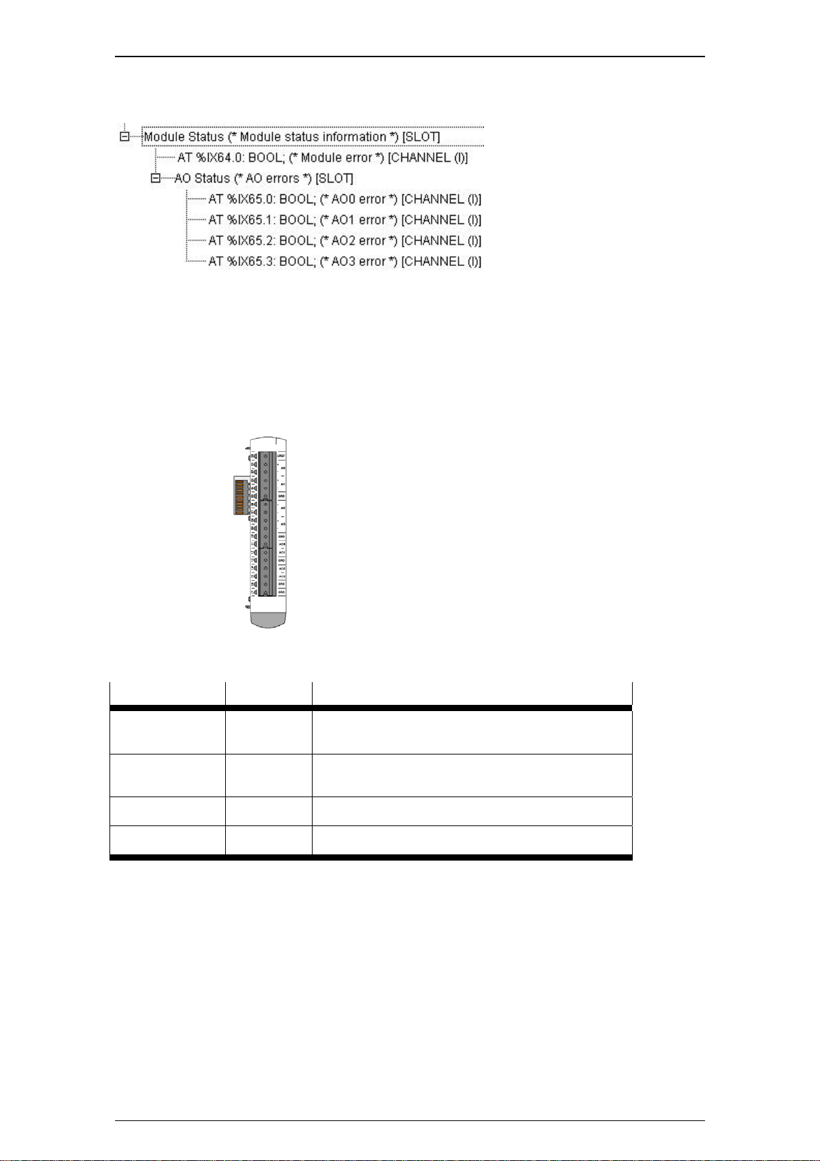
End points and status values of configured modules
When a module has been configured, CoDeSys creates end points which can be access ed in the IEC
program.
The following end points will be created:
One end point per input or output containing the measured value (e.g. the value V for an analog,
electrical signal).
A status value as diagnosis information for each module (module error: If this value is TRUE, an
error exists, otherwise not)
A status value for each end point (end-point error: If this value is TRUE, an error exists, otherwise
not)
Example for the end point and status values that have been created. The actual addresses are specified
by the concrete project and need not agree with the example shown here.
CECX-I 14

CECX modular control system
For a description of the stored status values: See the description of the configuration of modules in the
following chapters.
Process map
Input
Input
Treiber
physikalische
Inputs (Sensoren)
Output
Merker
Output
Treiber
physikalische
Outputs (Aktoren)
Byte addressing is used.
%IX0.0
-
%IX0.7
%IX1.0
-
%IX1.7
%IX2.0
-
%IX2.7
%IX3.0
-
%IX3.7
%IX4.0
-
%IX4.7
%IX5.0
-
%IX5.7
%IX6.0
-
%IX6.7
%IX7.0
-
%IX7.7
%IX8.0
-
%IX8.7
%IX9.0
-
%IX9.7
%IB0 %IB1 %IB2 %IB3 %IB4 %IB5 %IB6 %IB7 %IB8 %IB9
%IW0 %IW2 %IW4 %IW6 %IW8
%ID0 %ID4 %ID8
Attention:
In the system CECX the access of direct adressed BOOL-variables (%IX0.0, %QX0.0, %MX0.0) is not
possible. The access to bits must be always byte wise.
Address setting for modules
Die station address is set on the module via rotary switches (hexswitch).
The following rules apply for assigning addresses:
Modules of the same type (e.g. several CECX-D-16E modules), that have been added to the
In the CoDeSys configuration there are two options for specifying addresses:
1. Auto
2. Pre-defined value between 0 and F (Hex).
The "auto" setting is intended for those instances where the control does not contain several modules of
the same type. Here it is not necessary to inform the programming system of a fixed, pre-defined address.
A pre-defined value must be specified when several modules of the same type are used in the control a nd
the modules must be differentiated. The "address" module parameter specified in the configuration entry
must then agree with the switch position set on the module.
same CPU module, must have different addresses.
If this instruction is not adhered to and address conflicts result, it is possible that
modules are not recognized and that inputs/output settings are duplicated, set
incorrectly or not set at all.
Different type modules (e.g. a CECX-D-16E module and a CECX-A-4E4A-V module on a CPU
module) can use the same address settings.
CECX-I 15

CECX modular control system
The "auto" setting and the specific assignment of addresses should not be mixed in an
control system.
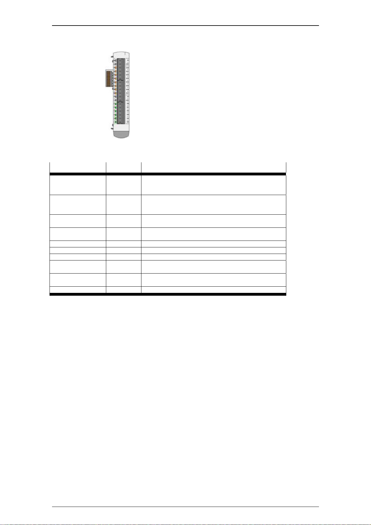
CECX-D-16E
Digital input module
16 digital inputs of type 1
Module parameters
Name Value Description
Address Auto The address set on the hex switch on the module is
recognized and taken over automatically. See
chapter "Address setting for modules".
0 - F The address set here (specified in hexcode) must be
brought into agreement with the position of the
address switch on the module.
DI0 - DI15: despike None No input signal debouncing.
100 ms Debouncing time 100 ms.
DI0 - DI1: Interrupt None No edge evaluation.
Rising edge Signal change at rising edge. *)
Falling edge Signal change at falling edge. *)
Both Signal change at every signal edge. *)
*) The two inputs DI0 and DI1 can be interrupted. i.e. they can trigger system events when corresponding
module parameters have been set. They can be evaluated with the functions of the 'EventData.lib" library.
Status values as diagnosis information
The following status values are created for this module (example):
CECX-I 16

CECX modular control system
Possible error states (when status = TRUE)
Module status: module is defective or missing.
DI status: no error message
CECX-D-14A-2
Digital output module
14 digital output modules 2A at 50%
coincidence, divided into 2 groups (6 and 8
outputs), short-circuit protected, overload
protection, short-circuit detection, group cut-off.
Module parameters
Name Value Description
Address Auto The address set on the hex switch on the module is
recognized and taken over automatically. See chapter
"Address setting for modules".
0 - F The address set here (specified in he xcode) must be
brought into agreement with the position of the address
switch on the module.
DO0..DO7: short
circuit scan,
DO8..DO13: short
circuit scan
Scan The short-circuit detection reactivates the outputs not
None This module has two output groups with separate
voltage supply. The short-circuit detection switches off
all active outputs of the output group in which the short
circuit occurred.
CECX-I 17

CECX modular control system
affected by the short circuit.
Status values as diagnosis information
The following status values are created for this module (example):
Possible error states (when status = TRUE)
Module status: module is defective or missing.
DO status: Short circuit of the outputs.
CECX-D-8E8A-NP-2
Digital input/output module
8 digital inputs sink, of which 2 are interruptible
8 digital outputs 2A source at 50% coincidence,
short-circuit protected, overload protection,
short-circuit detection, group cut-off
Module parameters
Name Value Description
Address Auto The address set on the hex switch on the module is
recognized and taken over automatically. See chapter
"Address setting for modules".
0 - F The address set here (specified in hexcode) must be
brought into agreement with the position of the address
switch on the module.
short circuit scan None The short-circuit detection deactivates all active outputs
of the output group.
CECX-I 18

CECX modular control system
scan The short-circuit detection reactivates the outputs not
affected by the short circuit.
DI0 - DI7: despike Non e No input signal debouncing.
100 ms Debouncing time 100 ms.
DI0 - DI1: Interrupt None No edge evaluation.
Rising
edge
Falling
edge
Both Signal change at every signal edge. *)
*) The two inputs DI0 and DI1 can be interrupted. i.e. they can trigger system events when corresponding
module parameters have been set. They can be evaluated with the functions of the 'EventData.lib" library.
Status values as diagnosis information
The following status values are created for this module (example):
Signal change at rising edge. *)
Signal change at falling edge. *)
Possible error states (when status = TRUE)
Module status: module is defective or missing.
DI status: no error message
DO status: short circuit of the outputs.
CECX-I 19
CECX modular control system
CECX-D-6E8A-PN-2
Digital input/output module
6 digital inputs source, of which 2 are
interruptible
8 digital outputs 2A sink at 50% coincidence,
short-circuit protected, overload protection,
short-circuit detection, group cut-off
Module parameters
Name Value Description
Address Auto The address set on the hex switch on the module is
recognized and taken over automatically. See chapter
"Address setting for modules".
0 - F The address set here (specified in hexcode) must be
brought into agreement with the position of the address
switch on the module.
short circuit scan None The short-circuit detection deactivates all active outputs
of the output group.
scan The short-circuit detection reactivates the outputs not
affected by the short circuit.
DI0 – DI5: despike None Debouncing time 1 ms.
100 ms Debouncing time 100 ms.
DI0 - DI1: Interrupt None No edge evaluation.
Rising
edge
Falling
edge
Both Signal change at every signal edge. *)
*) The two inputs DI0 and DI1 can be interrupted. i.e. they can trigger system events when corresponding
module parameters have been set. They can be evaluated with the functions of the 'EventData.lib" library.
Signal change at rising edge. *)
Signal change at falling edge. *)
CECX-I 20

Status values as diagnosis information
The following status values are created for this module (example):
CECX modular control system
Possible error states (when status = TRUE)
Module status: module is defective or missing.
DI status: no error message
DO status: short circuit of the outputs.
CECX-A-4E-V
Analog input/output module
Analog inputs +/- 10V or 0-10V, resolution 14-
bit, sensor failure detection
Module parameters
Name Value Description
Address Auto The address set on the hex switch on the module is
recognized and taken over automatically.
See chapter "Address setting for modules".
0 - F The address set here (specified in hexcode) must be
brought into agreement with the position of the address
switch on the module.
AI0 - AI3: operating
mode
-10..+10V Operating mode with differential input circuit.
CECX-I 21

CECX modular control system
0..URef Single-ended input circuit, calibration standardized to
URef.
Status values as diagnosis information
The following status values are created for this module (example):
Possible error states (when status = TRUE)
Module status: module is defective or missing.
AI status: sensor failure detection
CECX-A-4A-V
Analog input/output module
4 analog outputs +/- 10V, resolution: 12 Bit
Module parameters
Name Value Description
Address Auto The address set on the hex switch on the module is
recognized and taken over automatically.
See chapter "Address setting for modules".
0 - F The address set here (specified in hexcode) must be
brought into agreement with the position of the address
switch on the module.
CECX-I 22
Status values as diagnosis information
The following status values are created for this module (example):
Possible error states (when status = TRUE)
Module status: module is defective or missing.
AO status: no error mess age
CECX-A-4E4A-V
Analog input/output module
4 analog inputs universal +/- 10V, resolution: 14
Bit, sensor failure detection
4 analog outputs +/- 10V, resolution: 12 Bit
CECX modular control system
Module parameters
Name Value Description
Address Auto The address set on the hex switch on the module is
recognized and taken over automatically. See chapter
"Address setting for modules".
0 - F The address set here (specified in he xcode) must be
brought into agreement with the position of the address
switch on the module.
AI0 - AI3:
operating mode
0...URef Single-ended input circuit, calibration standardized to
Status values as diagnosis information
The following status values are created for this module (example):
-10 ... +10 V Operating mode with differential input circuit.
URef.
CECX-I 23

CECX modular control system
Possible error states (when status = TRUE)
Module status: module is defective or missing.
AI status: sensor failure detection
AO status: no error mess age
CECX-A-4E4A-A
Analog input/output module
4 analog inputs 0-20mA/4-20mA, resolution: 14
Bit
4 analog outputs 0-20mA/4-20mA, resolution:
12 Bit
Module parameters
Name Value Description
Address Auto The address set on the hex switch on the module is
recognized and taken over automatically. See chapter
"Address setting for modules".
0 - F The address set here (specified in he xcode) must be
brought into agreement with the position of the address
switch on the module.
AI0 - AI3:
operating mode
4...20 mA Input current range 4 to 20 mA, for detecting cable
Status values as diagnosis information
The following status values are created for this module (example):
0 ... 20 mA Operating mode with input current range 0 to 20 mA.
breakage.
CECX-I 24

Possible error states (when status = TRUE)
Module status: module is defective or missing.
AI status: sensor failure detection at 4...20 mA
AO status: no error mess age
CECX modular control system
CECX-E-4E-T-P1
Temperature measurement module
4 temperature inputs for PT 100 temperature
sensor
2 or 4 conductor technique
Module parameters
Name Value Description
Address Auto The address set on the hex switch on the module is
recognized and taken over automatically. See chapter
"Address setting for modules".
0 - F The address set here (specified in he xcode) must be
brought into agreement with the position of the address
switch on the module.
Status values as diagnosis information
The following status values are created for this module (example):
CECX-I 25

CECX modular control system
Possible error states (when status = TRUE)
Module status: module is defective or missing.
TI status: sensor failure detectio n
CECX-E-6E-T-P2
Temperature measurement module
6 temperature inputs for thermocouple type J, K,
L.
Cold junction compensation internal
Module parameters
Name Value Description
Address Auto The address set on the hex switch on the module is
recognized and taken over automatically. See chapter
"Address setting for modules".
0 - F The address set here (specified in hexcode) must be
brought into agreement with the position of the address
switch on the module.
operation mode internal
reference
microvolt is applied if the terminal temperature is measured with
TI0 - TI5: sensor
type
K For thermocouple type K (NiCr-Ni) according to IEC
L For thermocouple type L (Fe-CuNi) according to DIN
*) See online help section titled Target system - Festo CECX (hardware configuring,module CECX-E-6E-TP2, chapter Functional description).
Status values as diagnosis information
J For thermocouple type J (Fe-CuNi) according to IEC
The compensation of the terminal temperature is
achieved with an internal temperature measurement
sensor. *)
a semi-conductor temperature sensor (KTY type) with a
nominal resistance of 2,000 W. This semi-conductor
temperature sensor is connected to an analog input.
The cold junction compensation and the linearization
must be realized in the user program. *)
548-1 (-100 °C to 700 °C).
548-1 (-100 °C to 1000 °C).
43710/1977 (-100 °C to +700 °C).
CECX-I 26
The following status values are created for this module (example):
Possible error states (when status = TRUE)
Module status: module is defective or missing.
TI status: sensor failure detectio n
CECX-F-PB-S-V1 (12 Bytes, 32 Bytes, 64 Bytes)
PROFIBUS Slave interface module
PROFIBUS Slave DPV1, each with 32-byte or
64-byte data.
CECX modular control system
Module parameters
Name Value Description
Address Auto The address set on the hex switch on the module is
recognized and taken over automatically. See chapter
"Address setting for modules".
0 Only two modules of this type may be operated on one
CPU. An address setting is therefore
not required.
The required GSD file (CECX_F_FB_S_V1_6008.gsd) for the configuration of the PROFIBUS slave
module is stored in the IOCONFIG directory of the Target Support Packages.
Data
The data transmitted over the PROFIBUS are made available in the application in Bytes (Input byte 0 to
31, or 0 to 63 and Output byte 0 to 31, or 0 to 63).
With the configuration of a PROFIBUS slave, the first two data module must be kept
free with 'empty placeholders'! See image.
CECX-I 27

CECX modular control system
You can find more detailed information in the specification of the protocol PROFIBUS-DP (Decentralized
Peripherals) in the relevant field bus literature.
Status values as diagnosis information
The following status values are created for this module (example for 32-byte module):
Possible error states (when status = TRUE)
Module status: module is defective or missing.
BAI status: none.
BAO status: none.
CECX-F-PB-V1
PROFIBUS Master interface module
PROFIBUS Master DPV1.
The module is configurable in the PLC configuration at the lower-most "unused[SLOT]" (see image).
CECX-I 28

CECX modular control system
by selecting CECX-F-PB-V1.
For the use of Profibus DP-V1 services, set the module parameter DPV1Support of the
appropriate slave to "Enabled".
Please consider, that the behaviour of not all Profibus DP-V1-slaves conforms with the
standard. If the DP-V1 communication does not work with the "Enabled" setting, set it to
"Disabled".
Module parameters
A description of the parameters and data can be found in the CoDeSys online help under "Configuring
PROFIBUS modules".
Bus diagnosis
The library BusDag.lib is used for bus diagnosis.
The device number must be set for this as follows:
DEVICENUMBER = 2
Application example for usage of library „BusDiag_Lib“:
Declaration of variables:
PROGRAMM BusDiag_Lib_Profibus
VAR
DiagGBS : DiagGetBusState;
DiagGS : DiagGetState;
Diag : BOOL:=FALSE;
Stationsadress:DWORD; (*Stationsadress of the profibus slave*)
END_VAR
Program code:
DiagGBS(ENABLE := TRUE, DRIVERNAME := 0, DEVICENUMBER := 2);
// Initial situation: In the case of an error the bus has the state 7
// (DiagGBS.EXTENDEDINFO[Stationsadress]:= 7).
// In the following it is described, how to reset the bus state and how to
// get diagnosis information.
// 1. At the first ascending edge of the variable diag in case of an error
// the state of DiagGBS.EXTENDEDINFO[Stationsadress] is set from 7 (bus
// member reports an error) to 3 (bus member is active).
// 2. After the second ascending edge of the variable diag the diagnosis
// information is displayed in DiagGS.EXTENDEDINFO
DiagGS(ENABLE := Diag, DRIVERNAME := 0, DEVICENUMBER := 2,
BUSMEMBERID := Stationsadresse);
CECX-I 29

CECX modular control system
CECX-C-2G2
Motion extension module
Incremental encoder (500 kHz))
2 channels
Module parameters
Name Value Description
Address Auto The address set on the hex switch on the module is
recognized and taken over automatically. See chapter
"Address setting for modules".
0 - 7 The address set here (specified in hexcode) must be
brought into agreement with the position of the address
switch on the module.
Latch input type Sink Latch input DI0, DI1 (sink: switched to 24 V *)
Source Latch input DI0, DI1 (source: switched to 0 V). *)
INC0 - INC1:
encoder-type
RS-422 For encoders with RS-422output (5 V differential).
INC0 - INC1:
edge count
2x Encoder counter pulse 2-fold.
4x Encoder counter pulse 4-fold.
Counter Counter with track A, without direction detection.
Signed
INC0: DI0 - INC1:
DI1 latch edge
Rising edge Latch function activated at rising edge. *)
Falling edge Latch function activated at falling edge. *)
INC0 - INC1:
increments per
revolution
*) Additional latch functions can be used via the IncEnc.lib library.
**) With 24 V encoders no sensor failure and short circuit can be detected.
Status values as diagnosis information
The following status values are created for this module (example):
24 V Encoder interfaces INC0, INC1, incremental input, for
encoder wit 24V output (single ended). **)
1x Encoder counter pulse single.
Counter with track A and B, (with direction detection).
counter
None No latch function (= data storage at change of latch
input signal).
Number of impulses of transducer per rotation.
CECX-I 30

Possible error states (when status = TRUE)
Module status: module is defective or missing.
INC status: sensor failure, short circuit.
DI status: no error message
When parameter INC0 - encoder type (or INC1 - encoder type) is set on RS-422 and no
incremental encoder has been connected to the encoder input, the error state "INC Status"
switches to TRUE. Encoder inputs not used should therefore be configured as 24 V type.
CECX-S-2S1
CECX modular control system
Serial interface module
2 RS-232-C
Modul parameters
Name Value Description
address auto The address set on the hex switch on the module is
recognized and taken over automatically. See chapter
"Address setting for modules".
0 - F The address set here (specified in he xcode) must be
brought into agreement with the position of the address
switch on the module.
Status values as diagnosis information
The following status values are created for this module (example):
Possible error states (when status = TRUE)
Module status: module is defective or missing.
Additional information: See online help section titled Target system - Festo CECX (CECX- S-2S1).
CECX-I 31

CECX modular control system
CECX-C-2G1
Serial interface module
SSI Interface
4 interfaces
Modul parameters
Name Value Description
address auto The address set on the hex switch on the module is
recognized and taken over automatically. See chapter
"Address setting for modules".
0 - F The address set here (specified in he xcode) must be
brought into agreement with the position of the address
switch on the module..
baud rate 125, 250,
500 kBaud,
1 Mbaud.
data bits 16 – 24 Number of data bits
data code Binary oder
gray code
bit oder most
significant bit
first oder
least
significant bit
first
Status values as diagnosis information
The following status values are created for this module (example):
Data transmission rate.
Coding of the sensor. Gray code = after Frank Gray
coding process for robust transmission of digital values.
Specification of sequence in which the bits are
transmitted in the data stream.
Possible error states (when status = TRUE)
Module status: module is defective or missing.
Channel status: Sensor failure detection, sensor shows fault in SSI telegram.
CECX-I 32

CECX modular control system
CECX-C-S1, CECX-S-S4
Serial option module:
CECX-C-S1: RS-232-C,
CECX-S-S4: RS-485/422
Modul parameters
These modules are configured as CoDeSys interface in the PLC configuration via Communication
Parameters, SIO Config. For the application, these interfaces are useable via the functions from the
CoDeSys SysLib Com.
Name Values Description
Port COM2 to
COM8
baud rate Fr om 4800
to 115000
Baud
parity None, odd,
even
data bits 8 Number of data bits.
stop bits 0, 1 oder 2 Number of stop bits.
See also online help to the target system CECX under: Start-up of CoDeSys and control -> Establishing
PC/Control connection -> Serial connection.
See chapter "Operation of interfaces, Serial interfaces".
Data transmission rate.
Parity
CECX-B-CO
CANOpen bus link module:
for up to 12 add-on modules.
The CECX-B-CO is a CANOpen bus link module, and may be connected as slave module to each CAN
master module.
Set the values of the CAN parameters as desired (baudrate according to length of data line, other
parameters adequate to the settings at the CAN modules).
When configuring the CAN master, consider that the parameter „Support DSP301,V4.01 and
DSP306“ is selected. If this option is set, then the CAN module selection is available.
CECX-I 33

CECX modular control system
CAN module selection
Select the add-on modules of the bus link module via CAN-module selection.
At the bus the CECX-B-CO sorts the modules in the following sequence:
1. CECX-E-6E-T-P2 2. CECX-A-4E4A-V 3. CECX-A-4E4A-A
4. CECX-A-4E-V 5. CECX-A-4A-V 6. CECX-E-4E-T-P1
7. CECX-D-16E 8. CECX-D-14A-2 9. CECX-D-8E8A-NP-2
10. CECX-D-6E8A-PN-2 11. CECX-C-2G2 12. CECX-C-2G1
When adding modules take care that the modules selected are inserted in the sequence
described above. Otherwise data could be written onto the wrong modules.
When adding modules, they are inserted above the actual selected module. Do not start
selection with module of CECX-E-6E-T-P2 type.
PDO-Mapping
To ensure that data are transmitted between CAN-Master and CAN-Slave, the 'Receive PDO-Mapping'
and the 'Send PDO-Mapping' must be set right and complete.
In the left window select a data entry (in the example: Write Output 8-Bit_CECX-D-8E8A)
and a PDO (in the example: PDO 0x1400) and add it with the
not used here.
key. The StandardDataTypes must
CECX-I 34

CECX modular control system
The system configuration will be added with an entry.
If the message appears "Caution! The following PDOs are currently not active: ...", it can be ignored.
These are PDOs, which are created but not used in the system.
In the system configuration any name can be entered for the created system variable (e.g. out).
In principal the PDO mapping can be done arbitrary. If a PDO is filled, then a message will be shown, and
the next PDO has to be used.
Digital in-/output values are mapped to unsigned system variables (UINT for 16 bit transmission,
USINT for 8 bit). Bit 0 corresponds to the flirst in-/output, bit 1 to the second in-/output, and so
on. E.g. if the outputs 1, 2 and 4 should be set, then the variable out must be set to the value 11
(= 1+2+8).
For more detailed information to PDO mapping please refer to the system manual, chapter 34 - bus link
module CECX-B-CO.
CAN Master [SLOT]
Configuration entry for a CAN Master for operating CAN slaves.
If the CAN master is set on "unused" or on "Businterface", then the libraries "3S_CANDrv.lib",
"3S_CANOpenManager.lib" and "3S_CANOpenMaster.lib" that have been inserted
automatically must be removed manually, otherwise conflicts could arise during the
compilation of the project.
Bus diagnosis
The library BusDag.lib is used for bus diagnosis (see BusDiag.lib).
For this the DEVICENUMBER must be set as follows.
CAN Master that is used first: DEVICENUMBER = 3,
CAN Master that is used second: DEVICENUMBER = 4.
Information on application
A Start telegram is sent to each CAN participant as standard.
However, a "Start All Nodes" telegram, NodeID = 0, can be sent from the IEC application. For
the second CAN master the NodeID = 1.
This requires that at the start-up of the control the application always sets the flag
bUseStartAllNodes of the master once, e.g. as follows (bInit is defined by the application):
IF NOT bInit THEN
pCanOpenMaster[0].bUseStartAllNodes := TRUE;
bInit := TRUE;
CECX-I 35

CECX modular control system
END_IF
Attention:
This flag must not be set cyclically, since the individual nodes ca no longer be started after a
failure.
Application example for usage of library „BusDiag_Lib“:
Declaration of variables:
PROGRAM BusDiag_Lib_CAN
VAR
DiagGBS : DiagGetBusState;
DiagGS : DiagGetState;
Diag : BOOL:= FALSE;
NodeID: DWORD; //node number of the CAN slaves
CANMaster: INT; //First used CAN master: DEVICENUMBER = 3,
//Second used CAN master: DEVICENUMBER = 4
END_VAR
Program code:
DiagGBS(ENABLE := TRUE, DRIVERNAME := 0, DEVICENUMBER := CANMaster);
// Initial situation: In the case of an error the bus has the state 7.
// (DiagGBS.EXTENDEDINFO[NodeID] := 7).
// For requesting the diagnosis information in the case of an error
// (DiagGBS.EXTENDEDINFO[NodeID] := 7) the variable Diag must be set manually
// to TRUE.
// The emergency telegram is displayed in DiagGS.EXTENDEDINFO
IF Diag THEN
DiagGS(ENABLE := TRUE, DRIVERNAME := 0, DEVICENUMBER := CANMaster,
BUSMEMBERID := NodeID);
Diag := FALSE;
END_IF;
Bus interface [SLOT] (for Controller CECX-X-M1)
Configuration entry of a bus interface for SoftMotion drives.
When the bus interface and CAN master are operated simultaneously the f ollowing information must be
adhered to:
The bus interface must always be configured first in CoDeSys.
As soon as a CAN master is configured it occupies the first CAN circuit (Onboard CAN) and the bus
interface then occupies the plug-in module CECX-F-CO. The controller number at the AxisGroup
parameterization must in this case be set on 1 (see illustration).
CECX-I 36

CECX modular control system
Information on application
The cycle time for the motion task is configured depending on the used drives. If you use
CMMS-AS, CMMS-ST, SFC-LAC oder SFC-LACI the minimal cycle time is 8 ms.
For more information see the systemdescription of the drives.
Unused [SLOT]
Not used at the moment.
Notes on system behavior
The system behavior can, in certain cases, be influenced via application programming e.g. for:
Watchdog exception
Watchdog exception
A watchdog exception occurs when during a task in CoDeSys it is determined that the current cycle of the
maximum allowed time according to task configuration has been exceeded. This leads to the watchdog
exception callback of the Iec application being executed.
The system stops the task in which the exception has occured and the execution of al assigned
programms. The tasks subsequently execute no further cycle until an application reset was performed.
Other tasks of the taskconfiguration are not stopped. When the whole application is stopped, a start is only
possible after an application reset.
If a reaction is desired from the user, a watchdog exception handler must be added (Task configuration>System events):
The system behavior can be influenced as desired in this e.g. by call of a callback function. The name of
the called function must begin with "callback".
The behavior for a watchdog exception must be considered with the application design, e.g.:
switching from automatic to manual mode or reboot of the control. It is dependent on the
device function and the effects which the failure of the affected task can trigger.
The called callback function may not contain long continuing procedures (e .g. writing of files,
etc.) since otherwise the control will be totally blocked.
If a task with assigned programmcall is not defined in the project, a default task (realtime,
priority 10) with 10 ms cyle-time and active watchdog (time: t#11ms / sensitivity: 1) is used.
CECX-I 37

CECX modular control system
CECX-I 38

System manual CECX

CECX-II

Content System Manual CECX
Product design....................................................................................................................1-1
1 Introduction ..................................................................................................................1-1
1.1 Purpose of the document....................................................................................1-1
1.2 Target groups, preconditions..............................................................................1-1
1.3 Intended use of the CECX modular control system............................................1-2
1.4 Notes on this document......................................................................................1-3
1.5 General product-specific terms and abbreviation...............................................1-3
1.6 Application and registrations...............................................................................1-4
2 Safety notes..................................................................................................................2-1
2.1 Representation ...................................................................................................2-1
2.2 General safety instructions.................................................................................2-2
2.3 Safety instructions for programming...................................................................2-4
2.4 Safety instructions for maintenance work...........................................................2-5
2.5 Requirement for UL508 and use conforming to EN 61131.................................2-5
3 System overview ..........................................................................................................3-1
3.1 Structure of the modular control .........................................................................3-1
3.2 Working mode of the control...............................................................................3-4
3.3 Start-up and programming (overview) ................................................................3-5
4 General assembly and installation instructions........................................................4-1
4.1 General instructions on assembly and removal..................................................4-1
4.2 Mounting rail.......................................................................................................4-1
4.3 Footprint..............................................................................................................4-2
4.4 Adding modules..................................................................................................4-2
4.5 Mounting/dismounting the boards and modules.................................................4-3
4.6 Air conditioning, ventilation.................................................................................4-7
5 Power supply of modules............................................................................................5-1
5.1 Connection..........................................................................................................5-1
5.2 Power consumption of modules..........................................................................5-2
5.3 Example power calculation.................................................................................5-3
6 Operation and displays................................................................................................6-1
6.1 Setting the module address................................................................................6-1
6.2 Control key (Ctrl).................................................................................................6-1
6.3 Power LED (Power)............................................................................................6-1
6.4 Diagnosis display (Diagnostics)..........................................................................6-2
6.5 Compact Flash Card...........................................................................................6-2
7 Commissioning of CoDeSys and control...................................................................7-1
7.1 Installing CoDeSys and starting development environment ...............................7-1
7.2 Installation of a Target Support Package (TSP).................................................7-1
I

Content System Manual CECX
7.3 Switch-on control................................................................................................7-4
7.4 Creating a CoDeSys project...............................................................................7-4
7.5 Establishing the connection to the PC/control....................................................7-5
7.6 Configuring modules.........................................................................................7-15
7.7 Connecting an FED ..........................................................................................7-16
7.8 First programming steps...................................................................................7-20
8 Operating behavior ......................................................................................................8-1
8.1 Button and display, general information .............................................................8-1
8.2 Start-up...............................................................................................................8-2
8.3 Operating states ................................................................................................. 8-3
9 Diagnosis......................................................................................................................9-1
9.1 Display of errors in the 7-segment display..........................................................9-1
9.2 Touch control at error display during operations: ...............................................9-1
9.3 Error codes.........................................................................................................9-2
10 Disposal ......................................................................................................................10-1
10.1 Disposal of the module.....................................................................................10-1
10.2 Disposal of the battery......................................................................................10-1
11 Technical data ............................................................................................................11-1
12 EC directives and standards.....................................................................................12-1
12.1 Why EMC-compatible wiring?...........................................................................12-2
13 Connections and wiring.............................................................................................13-1
13.1 General information on interfaces.....................................................................13-1
13.2 General information on inputs / outputs ............................................................13-7
13.3 General limits for wire cross sections.............................................................13-11
13.4 Test of interference immunity .........................................................................13-12
14 CPU module................................................................................................................14-1
14.1 Introduction.......................................................................................................14-1
14.2 Safety notes......................................................................................................14-1
14.3 Description of the module.................................................................................14-4
14.4 Operating elements and displays .....................................................................14-6
14.5 Mounting and installation instructions...............................................................14-7
14.6 Air conditioning and ventilation.......................................................................14-10
14.7 Connections and wiring ..................................................................................14-11
14.8 Configuration ..................................................................................................14-19
14.9 Operating behavior of the CPU module..........................................................14-20
14.10 Diagnosis........................................................................................................14-20
14.11 Maintenance...................................................................................................14-21
14.12 Disposal..........................................................................................................14-23
14.13 Technical data ................................................................................................14-24
14.14 EC directives and standards...........................................................................14-25
15 Digital input module CECX-D-16E ............................................................................15-1
II

Content System Manual CECX
15.1 Introduction.......................................................................................................15-1
15.2 Safety notes......................................................................................................15-1
15.3 Description of the module.................................................................................15-3
15.4 Connections and wiring ....................................................................................15-4
15.5 Configuration ....................................................................................................15-9
15.6 Operating behavior.........................................................................................15-11
15.7 Disposal..........................................................................................................15-11
15.8 Technical data ................................................................................................15-12
15.9 EC directives and standards ...........................................................................15-13
16 Digital output module CECX-D-14A-2.......................................................................16-1
16.1 Introduction.......................................................................................................16-1
16.2 Safety notes......................................................................................................16-1
16.3 Description of the module.................................................................................16-3
16.4 Connections and wiring ....................................................................................16-5
16.5 Configuration ....................................................................................................16-8
16.6 Operating behavior...........................................................................................16-9
16.7 Disposal..........................................................................................................16-12
16.8 Technical data ................................................................................................16-13
16.9 EC directives and standards ...........................................................................16-14
17 Digital input/output module CECX-D-8E8A-NP-2 ....................................................17-1
17.1 Introduction.......................................................................................................17-1
17.2 Safety notes......................................................................................................17-1
17.3 Description of the module.................................................................................17-3
17.4 Connections and wiring ....................................................................................17-4
17.5 Configuration ..................................................................................................17-11
17.6 Operating behavior.........................................................................................17-12
17.7 Disposal..........................................................................................................17-14
17.8 Technical data ................................................................................................17-15
17.9 EC directives and standards ...........................................................................17-17
18 Digital input/output module CECX-D-6E8A-PN-2 ....................................................18-1
18.1 Introduction.......................................................................................................18-1
18.2 Safety notes......................................................................................................18-1
18.3 Description of the module.................................................................................18-3
18.4 Connections and wiring ....................................................................................18-5
18.5 Configuration ..................................................................................................18-12
18.6 Operating behavior.........................................................................................18-14
18.7 Disposal..........................................................................................................18-16
18.8 Technical data ................................................................................................18-17
18.9 EC directives and standards ...........................................................................18-19
19 Analog input module CECX-A-4E-V..........................................................................19-1
19.1 Introduction.......................................................................................................19-1
19.2 Safety notes......................................................................................................19-1
19.3 Description of the module.................................................................................19-3
19.4 Connections and wiring ....................................................................................19-5
19.5 Configuration ..................................................................................................19-10
19.6 Operating behavior.........................................................................................19-11
III

Content System Manual CECX
19.7 Disposal..........................................................................................................19-12
19.8 Technical data ................................................................................................19-13
19.9 EC directives and standards ...........................................................................19-15
20 Analog output module CECX-A-4A-V.......................................................................20-1
20.1 Introduction.......................................................................................................20-1
20.2 Safety notes......................................................................................................20-1
20.3 Description of the module.................................................................................20-3
20.4 Connections and wiring ....................................................................................20-5
20.5 Configuration ....................................................................................................20-8
20.6 Operating behavior...........................................................................................20-9
20.7 Disposal............................................................................................................20-9
20.8 Technical data ................................................................................................20-10
20.9 EC directives and standards ...........................................................................20-11
21 Analog input/output module CECX-A-4E4A-V.........................................................21-1
21.1 Introduction.......................................................................................................21-1
21.2 Safety notes......................................................................................................21-1
21.3 Description of the module.................................................................................21-3
21.4 Connections and wiring ....................................................................................21-5
21.5 Configuration ..................................................................................................21-12
21.6 Operating behavior.........................................................................................21-13
21.7 Disposal..........................................................................................................21-14
21.8 Technical data ................................................................................................21-15
21.9 EC directives and standards ...........................................................................21-17
22 Analog input/output module CECX-A-4E4A-A.........................................................22-1
22.1 Introduction.......................................................................................................22-1
22.2 Safety notes......................................................................................................22-1
22.3 Description of the module.................................................................................22-3
22.4 Connections and wiring ....................................................................................22-5
22.5 Configuration ..................................................................................................22-10
22.6 Operating behavior.........................................................................................22-11
22.7 Disposal..........................................................................................................22-12
22.8 Technical data ................................................................................................22-13
22.9 EC directives and standards ...........................................................................22-15
23 Temperature module CECX-E-4E-T-P1.....................................................................23-1
23.1 Introduction.......................................................................................................23-1
23.2 Safety notes......................................................................................................23-1
23.3 Description of the module.................................................................................23-3
23.4 Connections and wiring ....................................................................................23-5
23.5 Configuration ....................................................................................................23-9
23.6 Operating behavior.........................................................................................23-10
23.7 Disposal..........................................................................................................23-10
23.8 Technical data ................................................................................................23-11
23.9 EC directives and standards ...........................................................................23-13
24 Temperature module CECX-E-6E-T-P2.....................................................................24-1
IV

Content System Manual CECX
24.1 Introduction.......................................................................................................24-1
24.2 Safety notes......................................................................................................24-1
24.3 Description of the module.................................................................................24-3
24.4 Connections and wiring ....................................................................................24-5
24.5 Configuration ....................................................................................................24-9
24.6 Functional description.....................................................................................24-10
24.7 Operating behavior.........................................................................................24-13
24.8 Disposal..........................................................................................................24-13
24.9 Technical data ................................................................................................24-14
24.10 EC directives and standards...........................................................................24-16
25 PROFIBUS Master interface module CECX-F-PB-V1 ..............................................25-1
25.1 Introduction.......................................................................................................25-1
25.2 Safety notes......................................................................................................25-1
25.3 Description of the module.................................................................................25-3
25.4 Operating elements and displays .....................................................................25-4
25.5 Connections and wiring ....................................................................................25-5
25.6 Configuration ....................................................................................................25-7
25.7 Operating behavior...........................................................................................25-7
25.8 Disposal............................................................................................................25-8
25.9 Technical data ..................................................................................................25-9
25.10 EC directives and standards...........................................................................25-10
26 PROFIBUS Slave interface module CECX-F-PB-S-V1.............................................26-1
26.1 Introduction.......................................................................................................26-1
26.2 Safety notes......................................................................................................26-1
26.3 Description of the module.................................................................................26-3
26.4 Operating elements and displays .....................................................................26-4
26.5 Connections and wiring ....................................................................................26-5
26.6 Configuration ....................................................................................................26-8
26.7 7 Operating behavior........................................................................................26-8
26.8 Disposal............................................................................................................26-8
26.9 Technical data ..................................................................................................26-9
26.10 EC directives and standards...........................................................................26-10
27 Incremental encoder interface module CECX-C-2G2..............................................27-1
27.1 Introduction.......................................................................................................27-1
27.2 Safety notes......................................................................................................27-1
27.3 Description of the module.................................................................................27-3
27.4 Connections and wiring ....................................................................................27-5
27.5 Configuration ..................................................................................................27-11
27.6 Functional description.....................................................................................27-13
27.7 Operating behavior.........................................................................................27-18
27.8 Disposal..........................................................................................................27-19
27.9 Technical data ................................................................................................27-20
27.10 EC directives and standards...........................................................................27-22
28 Serial interface module CECX-S-2S1........................................................................28-1
28.1 Introduction.......................................................................................................28-1
28.2 Safety notes......................................................................................................28-1
V

Content System Manual CECX
28.3 Description of the module.................................................................................28-3
28.4 Operating elements and displays .....................................................................28-4
28.5 Connections and wiring ....................................................................................28-5
28.6 Configuration ....................................................................................................28-7
28.7 Disposal............................................................................................................28-8
28.8 Technical data ..................................................................................................28-9
28.9 EC directives and standards ...........................................................................28-10
29 SSI Interface module CECX-C-2G1...........................................................................29-1
29.1 Introduction.......................................................................................................29-1
29.2 Safety notes......................................................................................................29-1
29.3 Description of the module.................................................................................29-3
29.4 Operating elements and displays .....................................................................29-5
29.5 Connections and wiring ....................................................................................29-5
29.6 Configuration ....................................................................................................29-9
29.7 Operating behavior.........................................................................................29-10
29.8 Disposal..........................................................................................................29-10
29.9 Technical data ................................................................................................29-11
29.10 EC directives and standards...........................................................................29-12
30 CAN option module CECX-F-CO...............................................................................30-1
30.1 Introduction.......................................................................................................30-1
30.2 Safety notes......................................................................................................30-1
30.3 Description of the module.................................................................................30-3
30.4 Installation instructions .....................................................................................30-4
30.5 Display and operating elements .......................................................................30-6
30.6 Connections and wiring ....................................................................................30-7
30.7 Configuration ..................................................................................................30-10
30.8 Operating behavior.........................................................................................30-10
30.9 Disposal..........................................................................................................30-10
30.10 Technical data ................................................................................................30-11
30.11 EC directives and standards...........................................................................30-12
31 Serial option module CECX-C-S1 .............................................................................31-1
31.1 Introduction.......................................................................................................31-1
31.2 Safety notes......................................................................................................31-1
31.3 Description of the module.................................................................................31-3
31.4 Installation instructions .....................................................................................31-4
31.5 Connections and wiring ....................................................................................31-7
31.6 Operating behavior...........................................................................................31-9
31.7 Disposal............................................................................................................31-9
31.8 Technical data ................................................................................................31-10
31.9 EC directives and standards ...........................................................................31-11
32 Serial option module CECX-S-S4..............................................................................32-1
32.1 Introduction.......................................................................................................32-1
32.2 Safety notes......................................................................................................32-1
32.3 Description of the module.................................................................................32-3
32.4 Installation instructions .....................................................................................32-4
32.5 Connections and wiring ....................................................................................32-7
VI

Content System Manual CECX
32.6 EMC and wiring guidelines.............................................................................32-10
32.7 Operating behavior.........................................................................................32-11
32.8 Disposal..........................................................................................................32-11
32.9 Technical data ................................................................................................32-12
32.10 EC directives and standards...........................................................................32-13
33 Ethernet option module CECX-C-ET ........................................................................33-1
33.1 Introduction.......................................................................................................33-1
33.2 Safety notes......................................................................................................33-1
33.3 Description of the module.................................................................................33-3
33.4 Installation instructions .....................................................................................33-4
33.5 Connections and wiring ....................................................................................33-7
33.6 Configuration ....................................................................................................33-8
33.7 Operating behavior...........................................................................................33-8
33.8 Disposal............................................................................................................33-8
33.9 Technical data ..................................................................................................33-9
33.10 EC directives and standards...........................................................................33-10
34 Bus link module CECX-B-CO ....................................................................................34-1
34.1 Introduction.......................................................................................................34-1
34.2 Safety notes......................................................................................................34-1
34.3 Description of the module.................................................................................34-3
34.4 CANOpen protocol............................................................................................34-4
34.5 Operating elements and displays .....................................................................34-8
34.6 Connections and wiring ....................................................................................34-9
34.7 Configuration ..................................................................................................34-12
34.8 Operating behavior.........................................................................................34-21
34.9 Application example........................................................................................34-26
34.10 Object directory...............................................................................................34-28
34.11 Disposal..........................................................................................................34-60
34.12 Technical data ................................................................................................34-61
34.13 EC directives and standards...........................................................................34-62
VII

Content System Manual CECX
VIII

System manual CECX / Product design
Product design
The unit is available in the following designs:
Product design Description
CONTROLLER
CECX-X-C1
CONTROLLER
CECX-X-M1
In the following the unit is described as CECX modular control system or simply as control.
Modular controller CECX
Software: CoDeSys
Modular controller CECX
Software: CoDesys with SoftMotion
CECX-II 0-1

System manual CECX / Product design
CECX-II 0-2

System manual CECX / Introduction
1 Introduction
1.1 Purpose of the document
This document describes the structure of the CECX modular control system.
It further describes the assembly and installation, the wiring, the operation
and displays of the modules.
The installation and configuration is described to the extent that the user
has a CECX modular control system that is ready for operation.
"Ready for operation" means that the CECX modular control system or the
respective CPU modules are ready for the synchronization of the application.
1.2 Target groups, preconditions
The system manual is intended for all those using a CECX modular control
system that consists of CPU modules and I/O modules added in line or
those who plan to use such a system:
Target group Prerequisite knowledge and ability
Project engineer
Electrician
Programmer
Operator
Technical basic education (university of applied science, engi-
neering degree or corresponding professional experience),
Knowledge in:
- working mode of a PLC,
safety instructions,
the application.
Specialized training in the electro-technical field (in accordance
with industrial training guidelines).
Knowledge in:
safety instructions,
wiring guidelines,
circuit diagrams,
correct installation of electrical connections.
Technical training (university of applied science, engineering
training or corresponding professional experience).
Knowledge in:
- working mode of a PLC,
safety instructions,
programming a PLC (IEC61131).
Technical basic education (vocational high school, eng ineering
degree or corresponding professional experience),
Knowledge in:
safety instructions,
working mode of machine or plant,
principle functions of the application,
system analysis and troubleshooting,
setting options at the operating installations.
CECX-II 1-1

System manual CECX / Introduction
Target group Prerequisite knowledge and ability
Service technician
Technical basic education (vocational high school, eng ineering
degree or corresponding professional experience),
Knowledge in:
working mode of a PLC,
safety instructions,
working mode of machine or plant,
diagnosis possibilities,
systematic error analysis and troubleshooting.
1.3 Intended use of the CECX modular control system
A CECX modular control system may only be used for the type of use described in the technical description and only in conjunction with recommended/approved third-party equipment/installations.
All modules of the CECX modular control system have been developed,
manufactured, tested and documented in accordance with the appropriate
safety standards. Therefore, the products do not pose any danger to the
health of persons or a risk of damage to other property or equipment under
normal circumstances, provided that the instructions and safety precautions
relating to the intended use are properly observed.
The CECX modular control system is intended for installation in a switch
cabinet.
CoDeSys supports the programming languages described in the IEC-61131
standard.
The CECX modular control system is to be used as follows:
Only in the industrial sector
Only as directed
In original state without unauthorized modifications.
Authorized are the alterations or modifications described in the accompanying documentation.
In a faultless technical condition.
CECX-II 1-2

System manual CECX / Introduction
1.4 Notes on this document
Information
If necessary, also adhere to the documentation accompanying the modules.
1.4.1 Contents of the document
System overview
Start-up description
Operating behavior
Diagnosis
EMC and wiring guidelines
Technical data
1.4.2 Not contained in this document
Programming instruction
Application diagnosis
Firmware description
1.5 General product-specific terms and abbreviation
The following product-specific abbreviations are used in this document:
Term/abbreviation Significance
Terminating resistor Resistor for minimizing signal reflections. Terminal resistors must
be installed or joined at the line end of bus segments.
Modules Modules, also termed peripheral modules, establish the connection
with the process. Modules can be plugged into the right-hand side
of the CPU module to extend the range of functions. Signal trans-
ducers and actuators, for example, are linked with the I/O modules.
CPU module Central module of the CECX modular control system.
CANopen A field bus protocol based on CAN which has been standardized as
European standard.
Ethernet Physical protocol and network for linking different devices.
Incremental encoder Encoder
Option module Option modules serve for inserting in CPU modules. Option al mod-
ules for serial interfaces or different field bus links are available.
CECX-II 1-3

System manual CECX / Introduction
Term/abbreviation Significance
PROFIBUS PROcess Field BUS; process and field bus standard which has
been defined in IEC 61158 Type 3.
PROFIBUS address Serves for the clear identification of a bus participant in the
PROFIBUS
Project engineering
manual
Retain data Data that are written from the application into the memory of the
Status report Files which the unit can store for analyzing errors. They contain
Project engineering manuals are those documents that provide the
machine and plant project engineer with the necessary information
on the selection of the appropriate hardware. The project engineering manuals also provide information for the servicing and operating
personnel on the structure of the hardware components.
control system. These are normally quantities, time information, etc.
Retain data retain their value when the unit is switched on or off.
The stored data are used when the program is re-started. The data
are not stored on the compact flash memory card.
important information on the state of the unit at the time the error
occurred. They can be read out for service purposes.
1.6 Application and registrations
The product conforms to EU guidelines and carries the CE symbol.
Standards and test values which the product conforms to and meets are
contained in chapter Technical Data. For the EU guidelines relevant to the
product please see the declaration of conformity.
CECX-II 1-4

System manual CECX / Safety notes
2 Safety notes
2.1 Representation
At various points in this manual you will see notes and precautionary warnings regarding possible hazards. The symbols used have the following
meaning:
DANGER!
!
!
indicates an imminently hazardous situation which will result in death
or serious bodily injury if the corresponding precautions are not taken.
WARNING!
indicate s a potentially hazardous situation which, if not avoided, can
result in death or serious injury.
ATTENTION!
!
means th at if the corresponding safety measures are not taken, a po-
tentially hazardous situation can occur that may result in property injury or slight bodily injury.
CAUTION
CAUTIO N used without the safety alert symbol indicates a potentially
hazardous situation which, if not avoided, may result in damage to
property.
This symbol reminds you of the possible consequences of touching
electrostatically sensitive components.
Information
on use of equipment and useful practical tips are identified by the “Information” symbol. Notes do not contain any information that draws attention to
potentially dangerous or harmful functions.
CECX-II 2-1

System manual CECX / Safety notes
2.2 General safety instructions
The documentation contains information necessary for planning the use of
the CECX hardware.
Familiarity with and correct application of the information contained in these
manuals is a prerequisite for successful planning and safe installation,
commissioning and maintenance of automation systems. Only properly
qualified personnel have the required specialist knowledge to correctly interpret and implement the instructions given in this manual.
For reasons of clarity, not every single detail of every version of the products described is listed nor can every conceivable practical situation be
taken into consideration. Should you require additional information, please
contact the manufacturer.
When installing, commissioning and servicing CECX-products, adhere to
the instructions in the respective chapters of the hardware modules.
WARNING!
!
The following application areas are expressly excluded:
Use in explosive or fire-risk areas
Use in mining
Outdoor use
Other products without additional measures are to be used for these
applications!
The modules of the CECX modular control system are not designed for
safety-relevant control tasks (e.g.: shutdown in case of an emergency).
For safety-relevant control tasks or personnel safety, additional external safety measures must be implemented to ensure the system remains in a safe operating condition even in the event of a fault.
For addition al information see EN 954-1 (EN ISO 13849/1).
CECX-II 2-2

System manual CECX / Safety notes
ATTENTION!
!
Fire danger for component failure!
Ensure ad equate fuse protection of the 24 V DC power supply of the
CECX modular control system in the end usage!
The max. permitted fuse is 10A!
The 24V power supply for the equipment must be safeguarded by safe
separation of the extra low voltage circuits from any hazardous voltage
circuits.
CAUTION
Improper handling will destroy the module or the control system!
Turn off the power supply before inserting or removing the module.
Otherwise, the module can be destroyed or undefined signal states can
lead to damage of the control system.
When r emoved from the rack, the modules used in the system are sen-
sitive to electrostatic discharge. Before handling modules, touch a
grounded metal object in order to discharge any static electricity from
your body.
2.2.1 Personnel safety
WARNING!
!
Unqu alified interventions in the control may cause abnormal behavior
of the machine/plant or personal injury or damage to the equipment.
Only especially qualified staff may perform interventions in the control
system.
Protective earthing
The protective earthing is specified for all equipment with conductive housing if high voltage can occur inside the equipment. Relevant official directives (e.g. ÖVE, VDE) control the version of the protective earthing in most
countries.
If a fault occurs in the equipment, a short circuit to earth will be caused and
the power supply will be interrupted via the series connected protection device (fuse, fault-current circuit breaker,...).
CECX-II 2-3

System manual CECX / Safety notes
WARNING!
!
All parts o f the system that must be supplied with a voltage higher than
safety extra-low voltage (SELV according to EN 61131-2) and has
touchable metal parts, must be earthed. Otherwise, the series connected protection devices are ineffective.
2.2.1.1 Safety extra-low voltage
WARNING!
!
Danger of personal injury due to electric shock!
Supply the KEBA control exclusively from power sources that have a
protective low voltage (e.g. SELV or PELV according to EN 61131-2)
Conn ect only voltages and power circuits to connections, terminals
and interfaces up to 50 V rated voltage that have a secure disconnect
for hazardous voltages (e.g. with sufficient isolation and voltageproof).
2.3 Safety instructions for programming
ATTENTION!
!
The instru ctions contained in these manuals must be precisely fol-
lowed in all circumstances. Failure to do so could result in the creation
of potential sources of danger or the disabling of safety features integrated in the CECX modular control system.
Apar t from the safety instructions given in these manuals, the safety
precautions and accident prevention measures appropriate to the situation in question must also be observed.
Measur es must be taken to ensure that in the event of power dips or
power failures, an interrupted program can be properly restarted. In
such situations, no dangerous operating conditions must be allowed to
occur even temporarily.
In all situations where faults occurring on the automation system could
cause personal injury or significant damage to machinery and equipment, additional external safety measures must be taken in order to
ensure the system as a whole remains in a safe operating condition
even in the event of a fault.
CECX-II 2-4

System manual CECX / Safety notes
2.4 Safety instructions for maintenance work
Before opening the device:
1. Disconnect the power supply
2. Disconnect the interface connections
ATTENTION!
!
The device may only be opened by qualified personnel and only main-
tenance activities expressly approved by Festo may be performed (see
chapter “Service notes”). Any other manipulations to the device will
result in loss of warranty.
2.5 Requirement for UL508 and use conforming to EN 61131
The modules of the CECX modular control system are defined as "open
type" equipment (according to UL508) or as "offenes Betriebsmittel” (according to EN 61131) and must therefore be installed in a switch cabinet.
CECX-II 2-5

System manual CECX / Safety notes
CECX-II 2-6

System manual CECX / System overview
3 System overview
3.1 Structure of the modular control
The CECX modular control system is based on a modular concept and can
be structured according to specific functional requirements. It consists essentially of a selection of CPU modules, I/O modules and operating and
display units. CPU- and I/O-modules are joined together and form a control
block that can then be installed into a control cabinet. The operating and
display devices can be arranged at a suitable located somewhere on the
machine/plant. For the adoption to different interfaces, option modules are
slotted into the CPU-module.
The casing provides mechanical protection, the inner construction of the
module guarantees EMC shielding.
During the start of the system the CoDeSys compares the current hardware
configuration (actual configuration) with the hardware configuration stored
in the IEC project (setpoint configuration). Deviations in configuration or
faulty modules can be identified via the inquiry of the module status in the
IEC application. The response is there fixed programmatically (e.g. error
output on the visualization, restricted function in the optional I/O modules,
etc.)
A description of the CPU and I/O modules is contained in chapter "Hardware programming" at the end of this description.
CECX-II 3-1

System manual CECX / System overview
3.1.1 Structure of field bus systems
Field bus systems can be assembled by means of plug-in option modules
or add-on field bus modules. This enables communication with remote devices (filed bus slaves) and control systems. The installation of different option modules in the CECX modular control system makes coupling or a gateway function possible. For example, this makes cross-linking a CANopen
field bus system with a PROFIBUS-DP field bus system possible.
Ethernet
Ethernet
CAN -Bus
CAN -Bus
Profibus-DP
Profibus-DP
CPX / MP A
CPX / MP A
CECX
CECX
with option modules
with option modules
and I/Omodules
and I/Omodules
Machine Vision
Machine Vision
Example of a system structure with CPU module and periphery
FED
FED
CAN - Bus
CAN - Bus
CMMP-AS oder CMMS-ST
CMMP-AS oder CMMS-ST
CPI
CPI
CPV
CPV
MTR-DCI SFC-DC
MTR-DCI SFC-DC
CECX-II 3-2

System manual CECX / System overview
3.1.2 Display of data
3.1.2.1 CoDeSys
To enable the data of the CECX modular control system to be operated and
monitored does not require an additional tool apart from the CoDeSys programming system (data are displayed on the CECX modular control system
via LEDs, display or the activated visualization).
The Front End Display (FED) is available for the visualization and monitoring of processes and sequences in connection with the CECX modular control system.
3.1.2.2 Linking of Front End Displays (FED)
Festo front
end displays can communicate with t
he CECX modular control
system via a serial connection or an Ethernet connection.
The scope of supply from the designer of the FED includes appropriate
drivers which support the easy variable exchange on the basis of the symbol files (see also online Help of CoDeSys).
Attention:
Is in CECX a variable declared as BYTE, WORD or DWORD an bit wise
access via the FED is not possible. In general it is recommended to access
via variable names.
1 2
CAN0
RXTX
RS-485-A
1........ CECX modular control system 2.........Front End Display FED
Ethernet
CECX modular control system and FED
RS-485-A connection cable
This cable can be ordered from Festo.
Designation: NEBC-S1G15-K-2.5-N-B-S1G9-V, Order no. 563782.
See also chapter 7.6 "Connecting an FED".
CECX-II 3-3

System manual CECX / System overview
3.2 Working mode of the control
3.2.1 Program processing
The control operates according to the following principle: “Reading Inputs,
Processing, writing Outputs”. The CECX modular control system carries out
the following tasks during processing of each task defined with CoDeSys:
Reading inputs:
The actual states of the inputs are read at the start of a cycle and written into the process map of the inputs.
Processing:
The user program is being executed. The target state of the outputs is
copied into the process map.
Writing outputs: At the end of the cycle the target states of the outputs
stored in the process map are transferred to the physical outputs.
3.2.2 Configuration and addressing
The CECX modular control system can be made up of a host of modules
and linked with additional external devices.
The expansion of the CECX modular control system and its connected devices is fixed during configuration in CoDeSys. The available I/O channels
are displayed in the control configuration of CoDeSys and can be used in
the CoDeSys application.
The CECX modular control system can be expanded with add-on modules.
External devices can be connected via serial interfaces and field buses
(onboard or via option modules).
CECX-II 3-4

System manual CECX / System overview
3.2.3 Internal memory of the CECX modular control system
The available memory of the CECX modular control system is divided automatically under CoDeSys.
Please adhere to the following maximum sizes:
Memory Description Value
Code Working memory to execute the user
programs
Global data Data memory for IEC project 18,432 KByte
Marker Marker memory 8 KByte
Inputs Input map memory 8 KByte
Outputs Output map memory 8 KByte
Retain Battery-buffered SRAM 128 KByte
Marker-variables and retain-data are stored in different memories. Because
of this it is not possible to mark a retain variable.
6,144 KByte
3.3 Start-up and programming (overview)
The CoDeSys 2.3 development environment serves for the start-up and
programming of the CECX modular control system.
CoDeSys offers a comfortable user interface with the following functions:
Configuration and parameterization of the CECX modular control sys-
tem (with the control configuration)
Programming according to EN 61131-3 (see chapter Programming lan-
guages)
Integrated module libraries (see Description of library)
Library administrator for integrating additional libraries
Simulation mode (enables projects to be tested on the PC without PLC)
Documentation (integrated project documentation)
Debugging function (testing program sequence, monitoring and modify-
ing variables, error search).
To enable a control (target system) to be used under CoDeSys a so-called
target support package is required for the respective target system. This
enables the system functions of the target system to be accessed (and contains appropriate information in the form of online Help).
CoDeSys is supplied with the target support package for the CECX modular control system.
CECX-II 3-5

System manual CECX / System overview
3.3.1 Programming languages
CoDeSys offers all 5 programming languages standardized in EN 61131-3.
There are two textual and three graphic programming languages. Each of
these languages has specific characteristics that are ideally suited for carrying out specific tasks.
Programming languages
Instruction List
(IL):
Structured text
(ST)
Sequential Function
Chart
(SFC)
Function plan
(FUP)
and/or
Free graphic
function plan
(CFC)
Ladder Diagram (LD)
Type Description
Textual programming language
The instruction list enables the programmer to describe
the work processes of control tasks with simple instructions. The structure of the language enables complex
tasks to be carried out efficiently.
The structured text comes closest to the programming
languages Pascal and C used for the PC. It consists of a
series of instructions that can be executed in high-level
language ("IF..THEN..ELSE") or in loops (WHILE..DO).
Graphic programming language
Enables programming of sequences and is therefore
suited for structuring and arranging of projects.
The Sequential Function Chart describes the temporal
sequence of the various steps within the program with
transitions and connections.
The function chart works with a list of networks where
each network receives a structure which represents a
logical or arithmetical statement, the call-up of a function
block, a jump or a return instruction.
In addition, based on the function chart there is the continuous graphic function chart (CFC) in which elements
can be placed freely and feedback can be inserted directly.
The ladder diagram was developed from the circuit diagram. The representation of a ladder diagram resembles a
circuit diagram - relative to the representation of the logical links.
3.3.2 Libraries
To facilitate programming, CoDeSys makes it possible to organize objects
that are not related to projects into libraries, such as modules, declarations
and visualizations. For this purpose a library administrator is available for
integrating and viewing of libraries.
See online Help, key word "Libraries".
CECX-II 3-6

System manual CECX / System overview
3.3.3 Specific target system online Help
The specific target system online Help for the CECX modular control system is displayed only when the CECX modular control system has been set
as target system. Access to the Help is gained via the online Help table of
contents under "Target system".
This system manual is a component part of the specific target system Help
(see online Help).
CECX-II 3-7

System manual CECX / System overview
CECX-II 3-8

System manual CECX / General assembly and installation instructions
4 General assembly and installation instructions
4.1 General instructions on assembly and removal
CAUTION
Improper handling can damage the modules, option modules and the control system.
Switch off the operating and on-load power supply before carrying out
assembly, installation or maintenance work.
CAUTION
Damage to components!
Handle all modules and components with care. Please ensure the following:
Clean contact surfaces (to avoid contact faults).
Bus plugs that are not bent.
Ensure that no pieces of wires, fillings or swarf fall into the unit when
you are drilling holes or connecting wires.
4.2 Mounting rail
A steel rail TS 35x7.5 is to be used as mounting rail for the control. For the
sake of stability the screw distance, as shown in the illustration, must not
exceed 100 - 120 mm.
TS 35x7,5
Fixing of the mounting rail.
100 - 120 mm
CECX-II 4-1

System manual CECX / General assembly and installation instructions
4.3 Footprint
TS 35x7,5
0V
000102030405060708091011121314151617
CAN0
RXTX
000102030405060708091011121314151617
+24V
DO0
DO1
DO2
DO3
DI0
DI1
DI2
DI3
+
AI0
-
+
AI1
-
AO0
AO1
AGND
AGND
+24V
DI0
DI1
DI2
DI3
DI4
DI5
DI6
DI7
22,5
Mounting sketch
To ensure air circulation, a free space of at least 30 mm must be maintained over and underneath the modules.
0V
NC
NC
NC
NC
NC
NC
NC
NC
120 3030
50 70
4.4 Adding modules
Up to 12 modules (I/O, technology or field bus modules) can be lined up
next to each other in any order on the right side of the CPU module. The
connection between the CPU module and the added modules is established via a parallel K-Bus. The entire package is snapped onto a mounting
rail (mounting rail TS 35x7.5).
For the calculation of the number of modules that can be added, the specified performance value given in the technical specifications under "power
consumption 5 V on the K-Bus" and under "power consumption 24 V on the
K-Bus" must be used. This value must not exceed the value made available
for added modules of the CPU modules or the bus coupling modules.
CECX-II 4-2

System manual CECX / General assembly and installation instructions
Apart from the following exceptions up to 12 modules of the same kind can
be placed in line on a CPU module or on a bus link module allowing for the
power consumption and the bus load.
CECX-F-PB -V1: Max. 1 pieces can be added on
CECX-F-PB-S-V1: Max. 1 pieces can be added on
CECX-C-2G2:
A maximum of 8 pieces can be added on to a CPU module
CECX-C-2S1: Max. 4 pieces can be added on
CECX-C-2G1:
A maximum of 4 pieces can be added on to a CPU module
4.5 Mounting/dismounting the boards and modules
The individual modules are lined up next to each other and connected to
one another via the K-Bus plug. Each line is completely prepared this way
before being installed on the mounting rail (TS 35x7.5) as complete package.
Preparing for installing on the mounting rail:
1) Unpack modules.
2) Remove all side lids on the K-Bus plug except for the one on the
module to the extreme right.
3) Set address switch with a suitable screwdriver to the setting config-
ured in the application software. The same modules (i.e. those with
the same type designation) must be differentiated by the setting of the
address switch.
ATTENTION!
!
Atten tion must be given when setting the address switch with the
screwdriver that none of the surrounding components is damaged.
CECX-II 4-3

System manual CECX / General assembly and installation instructions
4) Plug together the modules with the CPU module to form one control
block. The CPU module must be positioned to the extreme left, the
add-on modules are added on to the right.
1 ... Remove the side cover
Plugging modules together
2 ... Press on the module until both locking
pins are engaged.
CECX-II 4-4

System manual CECX / General assembly and installation instructions
Information
When adding extension modules to a CPU module or to an existing group
of add-on modules ensure that the locking pins are properly engaged.
Furthermore, ensure that the entire package (CPU module and add-on
modules) is secured on either side with the end clamps to prevent it from
being displaced and to protect it against vibration.
If the package is not mounted accordingly its functionality may be impaired.
Installing the CECX modular control system
This is how the CECX modular control system is installed on the mounting
rail:
1) Pull out (unlock) all locking levers on the mounting rail.
2) Slightly incline the module(s) and place on the fixture of the mounting
rail.
3) Press the lower half of the module onto the mounting rail.
4) Lock all locking levers on the mounting rail one after the other.
5) Secure the module with end brackets (see next chapter: "End brack-
ets") against slipping or loosening due to vibration.
The module is now installed on the mounting rail. You can now start wiring
up the interfaces and the inputs/outputs.
CECX-II 4-5
System manual CECX / General assembly and installation instructions
Removing the CECX modular control system
CAUTION
Risk of damaging components during installation work under voltage.
Therefore, switch off the power supply and remove all cable connec-
This is how the CECX modular control system is removed from the mounting rail:
1) Turn off power supply
2) Remove all cable connections from the CECX modular control sys-
3) Pull out (unlock) all locking levers on the mounting rail.
4) Remove the modules from the mounting rail.
4.5.1 End fixture
To prevent the modules from slipping or loosening through vibration, an
end plate must be mounted on the left and right side of the mounting rail.
Standard type end fixtures regularly included in the delivery program of the
manufacturer can be used.
tions prior to starting dismantling work.
tem.
1
1........End brackets
End fixture plates
0V
000102030405060708091011121314151617
+24V
CAN0
RXTX
DO0
DO1
DO2
DO3
DI0
DI1
DI2
DI3
+
AI0
-
+
AI1
-
AO0
AO1
AGND
AGND
0V
000102030405060708091011121314151617
+24V
NC
NC
NC
NC
NC
NC
NC
NC
DI0
DI1
DI2
DI3
DI4
DI5
DI6
DI7
CECX-II 4-6

System manual CECX / General assembly and installation instructions
4.6 Air conditioning, ventilation
Ventilation holes for dissipating the heat are placed at the top and underside of the module. If the permissible ambient temperature is not exceeded,
no external fan will be needed. Make sure that the ventilation holes are not
covered.
Information
To guarantee the dissipation of heat, it is advisable to leave a free space of
at least 30 mm above and below the modules.
ATTENTION!
!
The oper ating temperature inside the control cabinet must not exceed
the permissible ambient temperature of the modules. If this cannot be
guaranteed through natural heat dissipation, an air conditioning of the
control cabinet must be provided.
When installed in a control cabinet attention must be given that the
area around the temperature inputs is not exposed to any temperature
changes. (e.g. no air conditioners with intermittent operating hours)
For further information about the calculation of the total power loss in the
control cabinet: In chap. Power consumption of the modules.
4.6.1 Use of air filters
Information
The user must ensure, by means of installation in a suitable housing, that
no pollution greater than pollution degree 2 occurs.
It is recommended to install the control modules in a dustproof, closed control cabinet. The ventilation holes of the control cabinet must be equipped
with air filters. The filter elements must be cleaned or replaced regularly.
CECX-II 4-7

System manual CECX / General assembly and installation instructions
CECX-II 4-8

System manual CECX / Power supply of modules
5 Power supply of modules
5.1 Connection
The modules are supplied with voltage via the K-Bus plug. For a module
formation with a CPU module this is done via the bus supply of the module
row. Within the decentralized module clusters this function is allocated to
the input transceiver. Each of these couplers has its own DC/DC-converter
that will convert voltages to the appropriate internal voltage.
24 V DC
0 V
10 A
10 A
10 A
0V
0V
0V
000102030405060708091011121314151617
000102030405060708091011121314151617
000102030405060708091011121314151617
+24V
DO0
CAN0
DO1
DO2
DO3
DO4
RXTX
DO5
DO6
DO7
DI0
DI1
DI2
DI3
COMPACT FLASH
DI4
DI5
DI6
DI7
USB
+24V
+24V
DO0
DO0
DO1
DO1
DO2
DO2
DO3
DO3
DO4
DO4
DO5
DO5
DO6
DO6
DO7
DO7
DI0
DI0
DI1
DI1
DI2
DI2
DI3
DI3
DI4
DI4
DI5
DI5
DI6
DI6
DI7
DI7
10 A
Pxxxxx-xxxxx
PWRCTRL
DIAG
SI0
0V
+24V
ETHCAN1SI1
Connection diagram for +24 V power supply
Recommended fuse protection: circuit line breaker LSS 10A – type B
WARNING!
!
The supply voltages must comply with SELV in accordance with EN
61131-2.
ATTENTION!
!
The supply voltages must be secured with max. 10 A in the end usage
(see graphic "Connection diagram for +24 V power supply")
Always turn off the power supply before mounting and dismounting
the module package.
CECX-II 5-1

System manual CECX / Power supply of modules
5.2 Power consumption of modules
For correct configuration of the system the technical data of the modules
must be used to calculate the required electric capacity for the power supply unit.
The power consumption of the modules available for the CECX modular
control system is contained in the following table:
Festo description Festo
part number
CECX-X-C1 553852 14 CECX-X-M1 553853 14 CECX-C-S1 553855 - 0.25
CECX-C-ET 553856 - 0.5
CECX-F-CO 553854 - 0.25
CECX-S-S4 553979 - 0.25
CECX-D-16E 552096 1 0.4
CECX-D-14A-2 552097 2.1 0.4
CECX-D-8E8A-NP-2 552099 1.9 0.4
CECX-D-6E8A-PN-2 553972 1.9 0.4
CECX-A-4E4A-V 552100 3.3 0.3
CECX-A-4E4A-A 552101 3.6 0.3
CECX-C-2G2 552117 - 0.6
Power
consumption
24 V
Power
consumption
5 V
CECX-F-PB-V1 553981 1.6 CECX-F-PB-S-V1 552102 - 1.4
CECX-E-4E-T-P1 553973 2.5 0.3
CECX-E-6E-T-P2 553974 1.6 0.6
CECX-A-4E-V 553975 2 0.3
CECX-A-4A-V 553976 1.9 0.3
CECX-C-2G1 553977 - 0.65
CECX-S-2S1 553978 - 0.4
CECX-B-CO 553980 - 4.5
The following chapter contains an example for calculating the capacity for
the power supply unit.
CECX-II 5-2

System manual CECX / Power supply of modules
5.3 Example power calculation
Calculation of the power input required for the following instrumentation.
0V
UREF
000102030405060708091011121314151617
000102030405060708091011121314151617
+24V
+
AI0
-
DO0
CAN0
DO1
+
AI1
DO2
-
DO3
GND
DO4
RXTX
COMPACT FLASH
USB
Pxxxxx-x xxxx
+
AI2
DO5
-
DO6
+
AI3
DO7
-
GND
DI0
DI1
AO0
DI2
AO1
DI3
GND
DI4
AO2
DI5
AO3
DI6
GND
DI7
GND
Pxxxxx-xx xxx
Power supply
of control
5.3.1 Calculation of the load
The following table lists the power required from the CPU module (called
CPU for short in the following) for the option modules and the add-on modules. The CPU itself has a consumption of 14 W.
5 V sided / [W] 24 V sided / [W] Comment
CPU module 10 45 Source (this power the CPU
Option module 1 0.25 0 Sink
Option module 2 0.25 0 Sink
Option module 3 0.5 0 Sink
Output module 0.4 1 Sink
Analog module 0.3 3.3 Sink
Subtotal 1.7 4.3
The power consumption determined in the subtotal is less than the power
that could be made available by the CPU.
This calculation check is required especially when many add-on modules
are to be operated together with a CPU.
Pxxxxx-xx xxx
PWRCTRL
DIAG
SI1
SI0
0V
+24V
ETHERNE T
CAN1
RXTX
ETHCAN1SI1
module can provide on the
K-Bus)
Subtotal of the option modules and the add-on modules.
5.3.2 Pow er supply design
The power supply unit must be designed for:
the power requirement of the CPU, the option modules, the add-on
modules and
the power required for all other connected loads (e.g. outputs that are
supplied by the module).
Power requirement for CPU + modules + assemblies =
14 + 1.7 + 4.3 = 20 W.
CECX-II 5-3

System manual CECX / Power supply of modules
Power requirement of loads =
Number of outputs * capacity * coincidence factor,
e.g. for 14 x 2 A - outputs:
14 * 2 A * 24 V * 0.5 = 336 W.
Total power requirement for the power supply unit: 20 + 336 = 356 W.
CECX-II 5-4

System manual CECX / Operation and displays
6 Operation and displays
6.1 Setting the module address
The modules in the system are addressed by means of a 16-position address switch. This enables all modules within a control package (consisting
of CPU module and a maximum of 12 add-on modules) to be differentiated.
The address switch is located on the side of the modules, underneath the
K-Bus plug. The address must be set prior to the assembly of the package.
See also the project engineering handbook of the components and the
modules.
Information
Modules of the same type must have different address switch positions
within one control package. Different modules in different control packages
may have the same address switch positions.
6.2 Control key (Ctrl)
The Ctrl key on the CPU modules is located next to the
7-segment display.
The Ctrl key is used to execute the following functions:
Start application
Stop application
Writing the status report
Deleting of retain data
Deleting the application and the configuration (create default status)
6.3 Power LED (Power)
The green Power LED on the CPU module is located above the CTRL key.
Display:
green illuminated: supply voltage given
dark: no supply voltage
CECX-II 6-1

System manual CECX / Operation and displays
6.4 Diagnosis display (Diagnostics)
A single-digit 7-segment display on the front side of the CPU module indicates the start-up modes and operating states. For details, refer to chapter
Operational behavior.
Diagnosis display
6.5 Compact Flash Card
To operate the CECX modular control system a Compact Flash Card with
the respective firmware and the application must be plugged into the Compact Flash slot. Depending on the application used the Compact Flash
Card can be used for storing machine data (e.g. mold data and recipes).
The Compact Flash Card cannot be used as removable medium since it also has system programs stored on it. The Compact Flash Cards supported
by the CECX modular control system can be requested and ordered from
FESTO.
CAUTION
The Compact Flash Card can sustain damage if handled incorrectl y!
Do not remove or plug in the memory card during operation.
Do not switch the unit off while it is writing on the memory card.
Do not use force when inserting the card into the slot.
Do not drop the card nor bend it.
Do not expose the memory card to humidity, heat and direct sunlight.
Keep the memory card away from electrostatic sources or magnetic
fields.
The slot is designed so that the Compact Flash Card can only be slotted into the slot in the one direction. The card should slide easily into the slot.
The status LED next to the eject key lights up when the control accesses
the card for writing or reading.
CECX-II 6-2

System manual CECX / Operation and displays
CAN0
RXTX
1
2
3
COMPACT FLASH
USB
1........ LED 2.........Eject key
3........ Slot
Position of the slot and the operating elements
CECX-II 6-3

System manual CECX / Operation and displays
Inserting the memory card
How to slot in a Compact Flash Card:
1) Turn off the power supply.
2) Carefully slot in the Compact Flash Card with slight pressure in the direction of the arrow until it engages.
Removing the memory card
1) Turn off the power supply.
2) Carefully press the eject key with a suitable object (e.g. blunt stylus).
The card is ejected by a few millimeters.
3) Carefully pull the card from the slot.
CECX-II 6-4

System manual CECX / Commissioning of CoDeSys and control
7 Commissioning of CoDeSys and control
Use the CoDeSys development environment to configure and commission
the CECX modular control system.
The following paragraphs describe the most important commissioning
steps.
7.1 Installing CoDeSys and starting development environment
CoDeSys is installed on your PC with an installation program.
Information:
Administrator rights are required for the installation of CoDeSys.
How to install the CoDeSys from the CD-ROM:
1) Close all programs.
2) Insert the enclosed CD-ROM into your CD-ROM drive. If auto-run is
activated on your system the installation starts automatically and you
can skip steps 3 and 4.
3) Select Execute in the Start menu.
4) Enter D:\setup (if necessary replace D with the letter of your CD-
ROM drive).
5) Follow the instructions on the screen.
During the installation process CoDeSys and a Target Support Package is
installed for the CECX modular control system.
That completes the installation. The control can now be switched on.
7.2 Installation of a Target Support Package (TSP)
To be able to install the TSP on the development PC the CoDeSys 2.3 development environment with the Install Target must be available on the PC.
To install the TSP proceed as follows:
1) Execute Install Target (Start -> Programs -> FESTO Software ->
CoDeSys V2.3 by Festo -> Install Target).
Window Install Target is displayed:
CECX-II 7-1

System manual CECX / Commissioning of CoDeSys and control
InstallTarget window for installing the Target Support Package on the PC
2) Click on Open and select the file corresponding to your system
(E.g. CECX-X-C1.tnf or CECX-X-M1.tnf) and click on Open.
3) On the left under Possible target systems select Festo AG u. Co.
KG and
4) Click on Install. If necessary, you may have to confirm the creation of
an installation directory.
Festo AG u. Co. KG will then be displayed on the right under Installed tar-
get systems.
CECX-II 7-2

System manual CECX / Commissioning of CoDeSys and control
InstallTarget window with installed target system
5) Click on Close.
The files of the target Support Package are now installed.
CECX-II 7-3
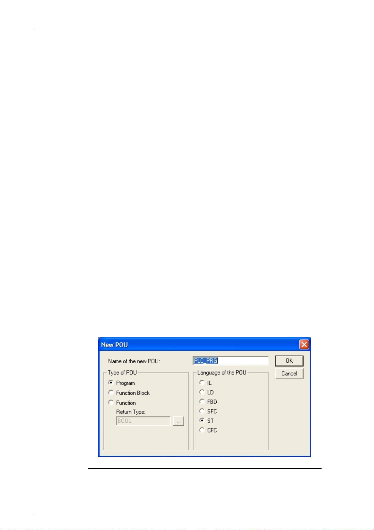
System manual CECX / Commissioning of CoDeSys and control
7.3 Switch-on control
1) Install the CECX modular control system with the necessary components, as described in chapter Installation.
2) Plug a network cable into the Ethernet connection of the control and
connect it either directly to the development PC (with the CoDeSys
development system installed) or via a network. See also chapter Es-
tablishing Ethernet connection to PC/control.
3) Ensure that the power supply has been properly connected.
4) Switch on the power supply. The LED on the central processor module lights up and the 7-segment display starts showing the start-up
steps.
When the 7-segment display shows 0, the start-up is complete and the control is ready for operation.
For further information on the display of the start-up procedure see chapter
Diagnosis.
7.4 Creating a CoDeSys project
1) Start the CoDeSys by clicking on the CoDeSys icon on the desktop or
with the command Start -> Programs -> Festo Software -> CoDe-
Sys V2.3 by Festo -> CoDeSys V2.3 or via a shortcut on the desk-
top.
2) Creat a new Codesys project via File -> New and select the Festo
control in the Configuration field. The window for a new module is
now opened.
Example for creating a new CoDeSys project
CECX-II 7-4

System manual CECX / Commissioning of CoDeSys and control
3) Switch on the control as described above.
7.5 Establishing the connection to the PC/control
There are two options for establishing a connection between the PC and
the control:
TCP/IP connection via Ethernet and
Connection via serial interface.
To establish a connection between PC and control, a project in CoDeSys
must first be created. See Creating a CoDeSys project.
7.5.1 TCP/IP connection
During the initial start-up of the CoDeSys and the CECX modular control
system the IP addresses of the devices have probably not yet been synchronized. That is why the network settings have to be established once
again.
The communication connection between the development PC and the control can be established as follows:
Direct connection via crossover Ethernet cable or
Connection via network with a 1:1 wired cable.
The network setting is therefore only marginally different and must be carried out in accordance with the instructions in the following paragraphs.
The network address can be automatically obtained if a DHCP server is
available in the network. If no DHCP server is present or there is a direct
connection between control and PC, a fixed network address is assigned.
For basic information on addressing in the Ethernet see Addressing in the
Ethernet (basics).
Information:
For questions related the network addresses please contact your network
administrator.
If the network settings are to be monitored or altered, this can be done in
CoDeSys.
1) In CoDeSys on tab Resources select PLC configuration.
2) In the navigation tree, click on Communication[SLOT].
One or multiple entries are shown under the FindPLC tab.
CECX-II 7-5

System manual CECX / Commissioning of CoDeSys and control
3) Select the control under the Find PLC tab and press Config.
The Communication parameters window opens for entering the network
settings.
After here, the network configuration only differs slightly depending on the
obtainment of the IP address. Select the appropriate one for you from the
following instructions.
7.5.1.1 Obtain IP address automatically via DHCP
If no DHCP
server is present, activate DHCP in t
he network configuration
first before you start the control. The control will then automatically be assigned an IP address. To do so, apply the following steps:
Example dialog 'IP config' for connection over network with active DHCP
1) Select in IP config Enable DHCP in order to facilitate an automatic
addressing by the DHCP server.
2) Close the Communication parameters dialog.
3) With Set as active PLC, the network settings of the selected control
(PLC) are taken over into the communication settings of CoDeSys.
4) Start up the control.
CECX-II 7-6

System manual CECX / Commissioning of CoDeSys and control
7.5.1.2 IP address fixed assignment
1) In the IP config tab, locate the parameter for entering in the network
setting.
If the control has already been entered as active PLC, the network parameters in IP config can no longer be modified (Communication [Slot] - Set
as active PLC).
Example dialog 'IP config' for the fixed assignment of an IP address
The following parameters can be entered:
Name Description
PLC name Name of the control in the network
IP IP address *)
Subnet Subnet mask *)
Gateway Gateway entry *)
Enable DHCP Enable automatic addressing by DHCP server. If selected
and there is no DHCP server available in the network,
then the set IP address is used.
Answer on find requests Relevant for network operation. When selected, the con-
trol answers to search requests.
Reboot on OK When selected. A reboot is carried out after OK, to take
over the settings.
Synchronize RTC with PC When selected. After confirmation with OK the selected
control takes over the date and time from the PC.
*) see network configuration examples.
2) With Set as active PLC, the network settings of the selected control
(PLC) are taken over into the communication settings.
CECX-II 7-7

System manual CECX / Commissioning of CoDeSys and control
7.5.1.3 Entering a new control
Via connections over the network, you can add new controls from the network in the control configuration.
1) Click on Communication[SLOT] in the navigation tree of the Control
configuration window.
2) Press the button Add PLC
The 'Add PLC' window opens.
3) Specify a name or an IP address of the control.
CoDeSys searches for the control. When it has been found:
4) Select the control and then press Config button.
See chapter IP address fixed assign
ment for possible parameters
7.5.1.4
Network configuration examples
Example: Stand-alone operation with
IP addr. 192.168.181.1
Stand-alone operation with a PC and a control
The last digit (Host ID) of the IP entry for the control must be different to the
IP address of the PC, and the first part (Net ID) must be the same.
Information:
The IP address and subnet mask of the PC can be read by entering ip-
config in the command line.
Subnet is set on 255.255.255.0. This makes 254 different addresses possible.
A Gateway entry is not required here (can be 0.0.0.0).
If Reboot on OK is checked in theCommunication parameters mask, the
control is automatically re-booted when the OK button is pressed. The control must be re-booted to take over the setting.
a PC and a control
IP addr. 192.168.181.2
CECX-II 7-8
 Loading...