

Page 1

Tempra 30 O
wall-hung, gas-fired,
sealed boiler,
for central heating
OPERATING, INSTALLATION AND MAINTENANCE INSTRUCTIONS
cod. 3540C12/0 - 02/2006
Page 2

2
Tempra 30 O
• Carefully read the warnings in this
instruction booklet, as they provide
important indications on the safety of
installation, operation and maintenance.
• The instruction booklet is an integral and
essential part of the product and must
be carefully kept by the user for future
reference.
• If the appliance is sold or transferred to
another owner, or if it is moved, always
check that the booklet accompanies the
boiler for reference by the new owner
and/or installer.
• The installation and maintenance operations must be performed according to
the standards in force, the instructions of
the manufacturer and must be carried out
by professionally qualified personnel.
• Incorrect installation or poor maintenance may cause damage to people, animals
or things. The manufacturer declines all
liability for damage deriving from errors
in the installation and operation of the
appliance, and in any case from the failure
to observe the instructions provided by
the manufacturer.
• Before performing any cleaning or
maintenance operations, disconnect
the appliance from the mains power
supply using the system switch and/or
the corresponding on-off devices.
• In the event of faults and/or poor operation of the appliance, it should be
deactivated. Do not attempt to repair
the appliance. Contact professionally
qualified personnel only.
• The products must only be repairedreplaced by professionally qualified
personnel, using original spare parts
only. Failure to heed this warning may
affect the safety of the appliance.
• To ensure the correct operation of the
appliance, annual maintenance must be
performed by qualified personnel.
• This appliance must only be used for the
purposes it has specifically been designed for. All other uses are considered
improper and thus dangerous.
• After having removed the packaging,
check that the contents are intact.
• The parts of the packaging must not be
left within the reach of children, as they
are potential sources of danger.
• In case of doubt do not use the appliance
and contact the supplier.
This symbol indicates “Warning” and is placed near all warnings regarding safety.
Such provisions must be strictly adhered to so as to avoid danger and damage to
people, animals and things.
This symbol highlights a note or an important warning.
Page 3

3
Tempra 30 O
1. Operating instructions ............................................................................4
1.1 Introduction ............................................................................................................4
1.2 Control panel ..........................................................................................................4
1.3 Ignition and shut-down ...........................................................................................5
1.4 Settings ...................................................................................................................5
1.5 Maintenance ............................................................................................................6
1.6 Troubleshooting ......................................................................................................6
2. INSTALLATION .......................................................................................7
2.1 General instructions ................................................................................................7
2.2 Place of installation .................................................................................................7
2.3 Water connections ..................................................................................................7
2.4 Gas connection .......................................................................................................9
2.5 Electrical connections .............................................................................................9
2.6 Flues ......................................................................................................................11
3. SERVICE AND MAINTENANCE ............................................................12
3.1 Settings .................................................................................................................12
3.2 Commissioning ......................................................................................................14
3.3 Maintenance ..........................................................................................................15
3.4 Troubleshooting ....................................................................................................17
4. CHARACTERISTICS AND TECHNICAL SPECIFICATIONS .....................20
4.1 Dimensions and fittings ........................................................................................20
4.2 Overall view and main components .....................................................................21
4.3 Hydraulic diagram .................................................................................................22
4.4 Technical data table ..............................................................................................23
4.5 Diagrams ...............................................................................................................24
4.6 Wiring diagram .....................................................................................................25
cod. 3540C12/0
Page 4

4
Tempra 30 O
fig. 1
1. OPERATING INSTRUCTIONS
1.1 Introduction
Dear Customer,
Thank you for having chosen the Tempra 30 O, an advanced-concept FERROLI wall-hung boiler featuring
cutting-edge technology, high reliability and constructional quality. Please carefully read this manual
and keep it for future reference.
The Tempra 30 O is a high efficiency heat generator for central heating systems, operating on natural
gas or LPG (the type of gas can be configured at the moment of installation) and managed by an advanced microprocessor-based control system.
The boiler body is made up of a copper heat exchanger, the special shape of which guarantees high
heat exchange efficiency in all operating conditions, and an atmospheric burner featuring electronic
ignition with ionisation flame control.
The boiler is intended for outdoor installation only.
The accessories supplied with the boiler also include a variable-speed pump, expansion vessel, safety
valve, air pressure switch, water pressure switch, temperature sensors and safety thermostat.
The microprocessor-based control system means that the operation of the appliance is almost comple-
tely automatic. The central heating output is automatically regulated by the control system according
to requirements. The domestic hot water output (with external storage installed) is automatically and
continuously controlled to ensure both comfort and economical operation.
The user simply has to set the temperature required inside the home (using the optional, yet recommended room thermostat) or set the system temperature and the required domestic hot water outlet
tem pe ra tu re. The regulation and control system will then ensure optimum operation all year round.
It MUST NOT be used for pool or spa heating.
1.2 Control panel
To access to the control panel, open the front door, unscrewing the two black knobs.
POS. DESCRIPTION
A OFF/ON/RESET switch
B Central heating temperature
setting
C Hydrometer
E Clock fitting
CEAB
bar
Burner on signal
Shut-down warning signal
Stand-by in central heating operation (light flashing)
Central heating request (light on)
Insufficient system pressure (light flashing)
Mains power (light on)
1
2
3
4
1
2
3
4
LED
Table 1
Page 5

5
Tempra 30 O
1.3 Ignition and shut-down
Ignition
• Open the gas cock upstream of the boiler.
• Close or insert any switches or power plugs upstream of the boiler
• Place the main switch “A” in the ON position.
• Place knob “B” in the Winter position and set the room thermostat, if fitted, to the required temperature value. At this point, the burner will ignite and the boiler will start operating automatically,
managed by its control and safety devices.
If, after having correctly performed the ignition operations, the burners do not ignite and the
shut-down warning light is on, wait around 15 seconds, then turn knob A to the RESET position
and release it. The control unit will be reset and will repeat the ignition cycle. If, after a number
of attempts, the burners do not ignite, refer to the paragraph on troubleshooting.
Shut-down
Close the gas cock upstream of the boiler, turn knob “A” to OFF and disconnect the appliance from
the mains power supply.
When the boiler is off the boiler anti-freeze protection is not active.
For extended periods of inactivity during the winter months, in order to avoid damage due to
freezing, all the water should be drained from the boiler, both the domestic hot water and the
central heating system; alternatively, drain only the domestic hot water and place the special
antifreeze fluid in the central heating system.
1.4 Settings
Summer/Winter setting and system temperature control
With knob “B” Fig. 1 in the position of the symbol (Summer), the central heating function is deactivated.
Only the production of domestic hot water is activated (with the optional external hot water cylinder
installed).
With the knob “B” Fig. 1 in the position of the symbol
(Winter), both the central heating function
and domestic hot water are active.
Turning the knob clockwise increases the central heating water temperature, anticlockwise decreases
it. The temperature can be set from a minimum of 35° to a maximum of 85°. It is not recommended,
however, to operate the boiler below 45°.
Setting the ambient temperature (using the optional room thermostat)
Set, using the room thermostat or remote control, the temperature required inside the rooms. Based
on the command from the room thermostat, the boiler is ignited and heats the system water to the set
central heating outlet temperature. When the required temperature inside the rooms is reached, the
boiler switches off.
If no room thermostat or remote control is available, the boiler will maintain the system at the set central
heating outlet temperature.
Domestic hot water temperature control
Set the storage temperature, using knob “D” (supplied in the optional kit).
Page 6

6
Tempra 30 O
Before calling the service centre, check that the problem is not due to no gas or mains power
supply.
System water pressure control
The boiler is fitted with a cock for manually filling
the central heating system. The filling pressure when
the system is cold, as read on the boiler hydrometer,
must be around 1.0 bar.
If the pressure drops during operation (due to the
evaporation of the gas dissolved in the water) to a
value lower than the minimum described above, the
User must restore the initial value using the filling
cock. Once the operation is completed, always close
the filling cock.
1.5 Maintenance
It is recommended to have annual maintenance of the heating system performed by qualified personnel, and at least biennial checks on the combustion device. Please refer to Chap. 3.3 in this manual for
further information.
The casing, the control panel and the aesthetic parts of the boiler can be cleaned using a soft and damp
cloth, dipped in soapy water if necessary. Do not use abrasive detergents or solvents.
1.6 Troubleshooting
Any anomalies or operating faults are signalled by the LEDs on the control panel.
The following table lists the faults that may arise due to simple problems that can be resolved by the
user.
fig. 2
bar
Table 2
Boiler shut-down
Insufficient system pressure
(light flashing)
LED
Check if the gas cocks upstream of the boiler and on the counter are
open.
Turn knob A Fig. 1 to Reset and then release it.
In the event of repeated boiler shut-downs, contact the nearest service
centre.
Fill the system when cold to 1-1.5 bar, using the cock located on the
boiler.
Close the cock after use.
Problem Solution
Filling cock
Page 7

7
Tempra 30 O
2. INSTALLATION
2.1 General instructions
This appliance must only be used for the purposes it has been specifically designed for. This
appliance is used to heat water to below boiling temperature at atmospheric pressure and must
be connected to a central heating and/or hot warm distribution system, according to its characteristics, performance and heating capacity. All other uses are considered improper.
THE APPLIANCE SHALL BE INSTALLED IN ACCORDANCE WITH THE MANUFACTURED'S INSTALLATION INSTRUCTIONS, LOCAL GAS FITTING REGULATIONS, MUNICIPAL BUILDING CODES, WATER
SUPPLY REGULATIONS, ELECTRICAL WIRING REGULATIONS, AS 5601 / AG 601 - GAS INSTALLATIONS AND ANY OTHER RELEVANT STATUTORY REGULATIONS.
Incorrect installation may cause damage to people, animals and things. The manufacturer will not be
held liable in such events.
2.2 Place of installation
The appliance is intended for outdoor installation only.
The place of installation must in any case be free of dust, inflammable objects or materials and corrosive
gases.
The boiler is supplied ready for wall-hung installation. The rear frame of the appliance has a two slots
for fastening it to the wall, using screws with metal wall plugs. The fastening to the wall must provide
stable and effective support of the appliance.
Upon request a metal wall drilling template is available. This is used exclusively to trace the holes for
fastening the appliance onto the wall, and can be reused for more than one appliance.
2.3 Water connections
The heat capacity of the appliance should be established in advance by calculating of the heating requirements of the building according to the standards in force. For correct operation and long-life of
the boiler, the hydraulic system must be suitably proportioned and always fitted with all the accessories
that guarantee regular operation.
In the case where the central heating outlet and inlet pipes follow paths whereby, at some points, pockets of air may form, air vent valves should be installed at such points.
In addition, a drain device should be installed at the lowest point in the system, to allow complete
emptying.
If the boiler is installed at a lower level than the system, a flow-stop valve should be fitted to prevent
the natural circulation of water in the system.
The thermal head between the outlet manifold and the return inlet of the boiler should not exceed
20°C.
Do not use the water pipes as the earth for electrical appliances.
Before installation, carefully clean all the pipes in the system to remove any residues or impurities that
may affect the correct operation of the appliance.
Make the connections to the corresponding fittings, as shown in fig. 3.
Page 8

8
Tempra 30 O
It is recommended to fit on-off valves between the boiler and the central heating system; these allow
the boiler to be isolated from the heating system, if necessary.
Make the connections to the boiler in a way that its internal tubing is not subject to stress.
fig. 3a
The connection kit shown in fig. 4a and 4b can be supplied upon request.
In the boiler
From the system
From the system
In the boiler
From the system
In the boiler
In the boiler
From the system
A
F
C D E
FEDB CA
Connection with cocks
Connection with nipples
A Female pipe coupling
C OR gasket
D OT 58 stop ring
E Copper washer
F OT 58 connecting pipe
G Ball cock
A Female pipe coupling
B OT 58 nipple
C OR gasket
D OT 58 stop ring
E Copper washer
F OT 58 connecting pipe
G
fig. 4a
fig. 4b
Key
1 CH flow, 3/4”
2 Filling cock
3 Gas inlet, 1/2”
4 CH return, 3/4”
5 Pressure relief valve discharge
46,5 95 54 223,5 141
123
4
5
236,5
326,5
85
99
Gas inlet
3
Conical
ISO 7-1
Gasket
fig. 3b
Mount threaded adapter
before installation
Page 9

9
Tempra 30 O
Pressure relief valve
Tempra 30 O incorporates a pressure relief valve discharging at 300 kPa.
The discharge of the pressure relief valve must be con nect ed to a collection container, to avoid
water spill ing onto the ground in the event of over-pres sure in the central heating circuit. The
man u fac tur er of the boiler will not be held liable if this warn ing is not heeded, and the discharge
valve in ter venes and floods the room.
Characteristics of the system water
In the case of water with hardness above 25 French degrees, the water should be suitably treated,
to avoid any deposits in the boiler caused by hard water, or corrosion caused by aggressive water. It
should also be remembered that even minor deposits measuring just a few millimetres thick can cause,
due to their low thermal conductivity, significant overheating of the walls of the boiler, with consequent
serious problems.
The water must always be treated in the case of very large systems (with high water capacity) or systems with the frequent inlet of recovered water. If, in these cases, the system needs to be partially or
completely emptied, it must be refilled with treated water.
Filling the boiler and the system
The boiler is fitted with a ball cock for manually filling the central heating system. The filling pressure,
when the system is cold, must be around 1 bar. If the pressure drops during operation (due to the evaporation of the gas dissolved in the water) to a value lower than the minimum described above, the User
must restore the initial value using the filling cock. For correct boiler operation, the pressure, when hot,
must be around 1,5÷2 bar. Once the operation is completed, always close the filling cock.
2.4 Gas connection
Before making the connections, check that the appliance is configured for operation with the
type of fuel available, and carefully clean all the gas pipes in the system, to remove any residues
that may affect the correct operation of the boiler.
The gas connections must be made at gas inlet (see fig. 3 - key 3), with a rigid metal pipe, or a stainless
steel flexible continuous-wall pipe, fitting a gas cock between the system and the boiler. Before installation, mount the threaded adapter ISO 7-1 contained in boiler package, as shown in fig. 3b. Check that
all the gas connections for tightness.
The capacity of the gas counter must be sufficient for the simultaneous use of all the connected appliances.
The diameter of the gas pipe, which leaves the boiler, does not necessarily determine the choice of the
diameter of the pipe used between the appliance and the gas counter; this must be chosen according
to its length and the pressure drop, according to the standards in force.
Do not use the gas pipes as the earth for electrical appliances.
2.5 Electrical connections
Connection to the mains power supply
The boiler should be connected to a single-phase, 240 Volt-50 Hz electrical line.
The electrical safety of the appliance is ensured only when the appliance is correctly connected
to an effective earth system, as prescribed by the safety standards in force. Have professionally
qualified personnel check the efficiency and the rating of the earth system. The manufacturer
is not liable for any damage caused by the appliance not being correctly earthed. In addition,
make sure that the electrical system is adequately rated for the maximum power absorbed by
the appliance, indicated on the boiler rating plate, and in particular that the cross-section of the
wires is suitable for the power absorbed by the appliance.
The boiler is pre-wired and fitted with a cable for connection to the electrical line. The connections to
the mains supply must be made using a fixed connection, featuring a two-pole switch with a contact
Page 10
10
Tempra 30 O
Room thermostat
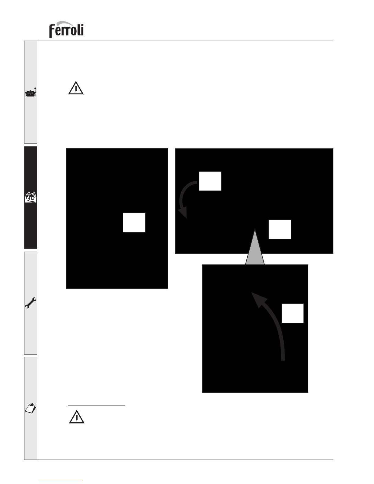
WARNING: THE ROOM THERMOSTAT MUST NOT HAVE LIVE CONTACTS. CONNECTING
240V TO THE ROOM THERMOSTAT TERMINALS WILL CAUSE IRREVERSIBLE DAMAGE TO
THE ELEC TRON IC BOARD.
When connecting a room thermostat with a daily or weekly program, or a timer, avoid taking the
power supply to these devices from their switch contacts. Their power supply must derive from
a direct connection to the mains or using batteries, depending on the type of device.
fig. 5b
fig. 5a
opening of at least 3 mm. Max 3A fuses must be installed between the boiler and the line. The correct
polarity must be followed (PHASE: brown wire / NEUTRAL: blue wire / EARTH: yellow-green wire) in
the electrical connections.
If the supply flexible cord is damaged or the unit needs repairs it shall only be done by a qualified
person authorised by the supplier.
If replacing the electrical power cable, use only the “HAR H05 VV-F” cable, 3x0.75 mm2, with a
maximum external diameter of 8 mm.
Accessing the electrical terminal block
Follow the indications shown in figs. 5a and 5b to access to the electrical terminal block. The layout of
the terminals for the various connections is shown in the wiring diagram, in the chapter on Technical
Specifications.
1
2
3
4
Page 11
11
Tempra 30 O
2.6 Flues
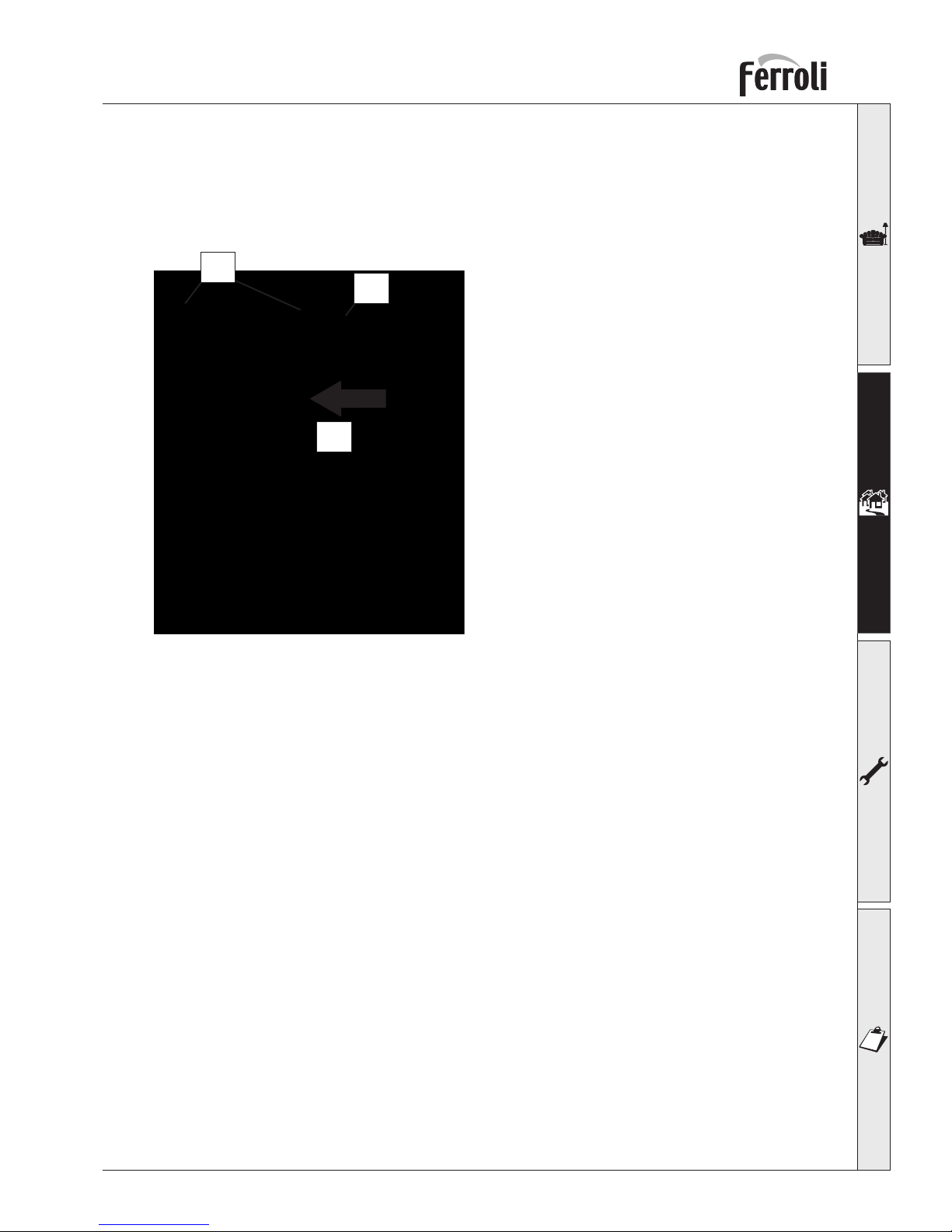
Boiler is supplied as standard with horizontal concentric terminal, exit on front panel.
For correct operation of the boiler it is necessary to mount the concentric terminal followiong instruc-
tioins below:
1) Mount and fix boiler on the wall.
2) Insert rubber gasket on terminal.
3) Insert terminal on appliance concentric bend. Be
sure to insert completely terminal on the bend.
4) Push gasket on boiler front panel. Check correct
sealing between gasket and front panel.
1
2
3
Page 12
12
Tempra 30 O
IN OUT
C
F
EB A D
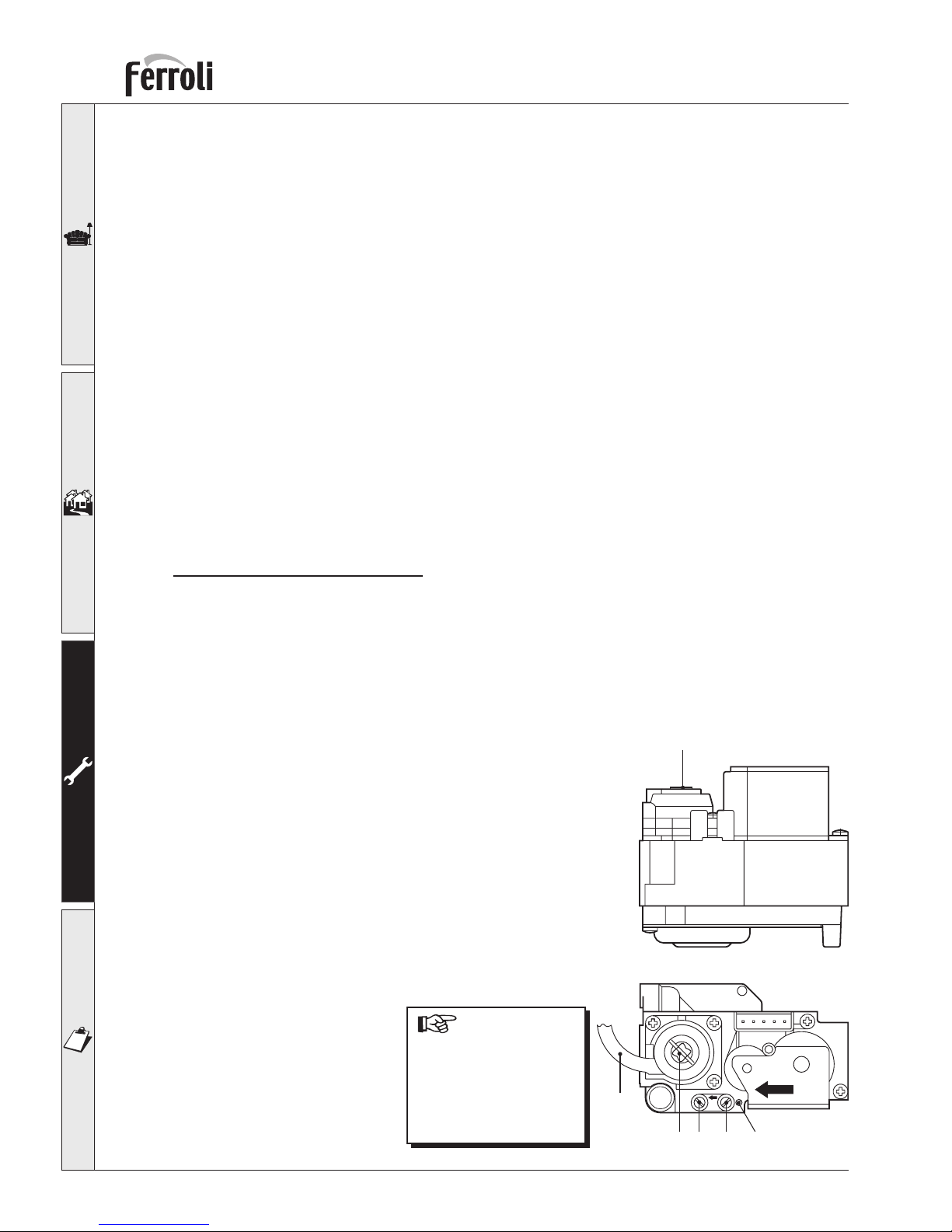
Key
A Pressure test point upstream
B Pressure test point downstream
C Protection screw
D Minimum pressure adjustment screws
E Maximum pressure adjustment screws
F Pressure compensation pipe
3. SERVICE AND MAINTENANCE
3.1 Settings
All the adjustment and conversion operations must be performed by Qualified Personnel, such as personnel from the Local Customer Service Centre.
FERROLI S.p.A. declines all liability for damage to persons and/or things deriving from tampering with
the appliance by non-authorised persons
Conversion of supply gas
The appliance can operate on Natural Gas or LPG as the supply gas, and is factory configured for use
with one of the two gases, as is clearly marked on the packaging and on the rating plate on the appliance itself. If the appliance has to be used with a gas other than the one it has been set for, the special
conversion kit must be used, as shown below:
1 Replace the nozzles in the main burner, installing the nozzles indicated in technical data table in Chap.
4, according to the type of gas used
2 Adjust the minimum and maximum pressures in the burner (ref. corresponding paragraph), setting
the values indicated in technical data table for the type of gas used.
3 Change the position of Jumper 02 on the electronic board (ref. corresponding paragraph).
4 Apply the adhesive label in the conversion kit next to the rating plate, to confirm the conversion
operation.
Adjusting the burner pressure
This appliance, featuring flame modulation, has two set pressure values: the minimum and maximum,
which must be the values indicated in technical data table, according to the type of gas.
• Connect a suitable pressure gauge to the pressure test point “B”, located downstream of the gas
valve.
• Disconnect the pressure compensation pipe “F”.
• Remove the protection cap “C”.
• Turn the potentiometer P3 (located on the control board) to the minimum position (anticlockwise).
• Operate the boiler in central heating mode.
• Adjust the minimum pressure using the screw “D”, clockwise
to decrease it and anticlockwise to increase.
• Turn the potentiometer P3 to the maximum position
(clockwise).
• Adjust the maximum pressure using the screw “E”, clockwise
to increase it and anticlockwise to decrease it.
• Reconnect the pressure compensation pipe “F”.
• Replace the protection screw “C”.
Once the pres-
sure check or ad just ment has been per formed, the adjustment
screws must be sealed
using the cor re spond ing
seal or paint.
fig. 6
Page 13
13
Tempra 30 O
Adjustments on the electronic board
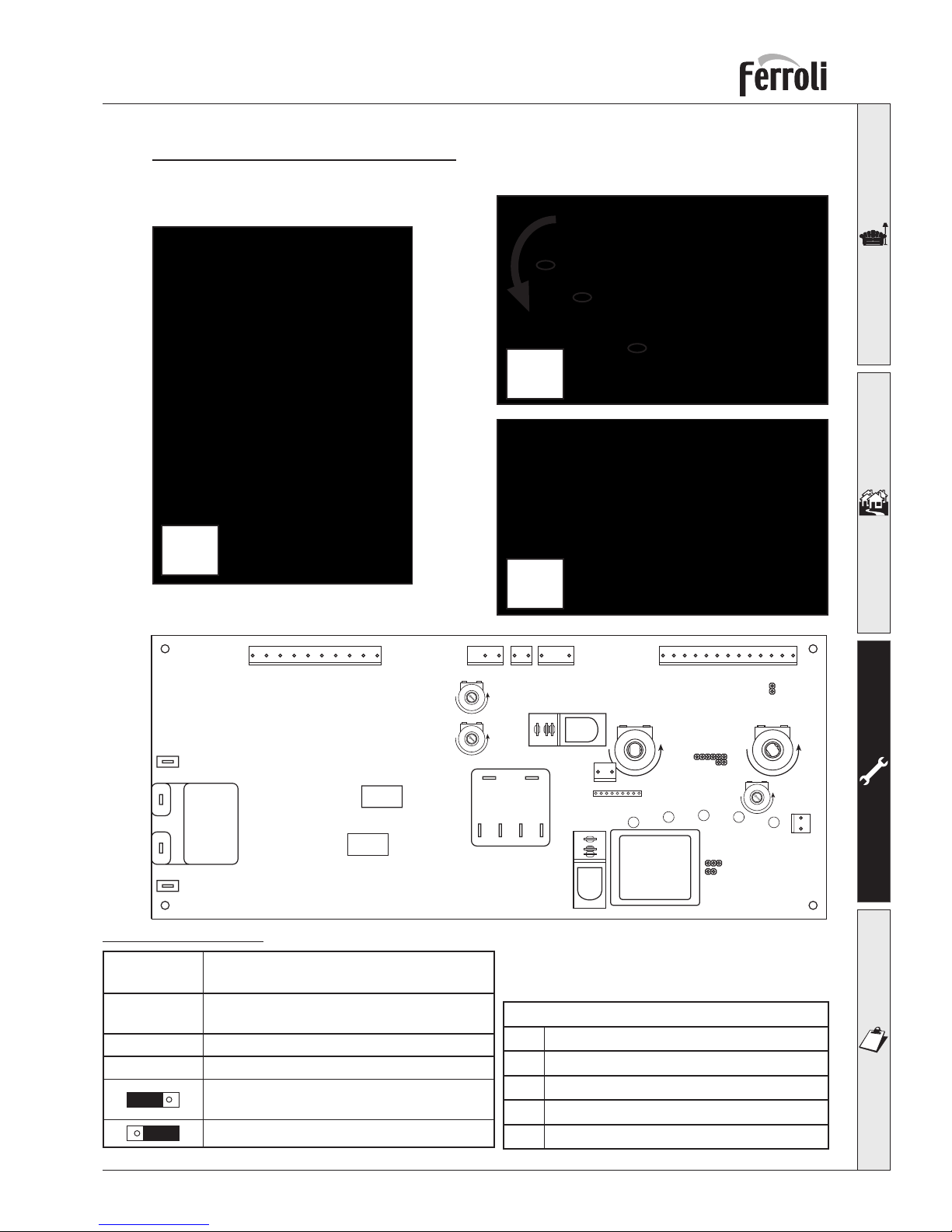
Follow the indications shown in the figure to access the electronic board.
Potentiometer adjustment
P1
Central heating temperature adjustment
P2
Domestic hot water temperature control
P3
Heating output adjustment
P4
Gas pressure adjustment for ignition
P5
Factory set; do not tamper
X6
X1 X2 X3 X4
12121312345678910 123
45
678910
111213
21
X5
L1
L2
L3
L4
L5
+- +-
Transformer
P2
DHW
X12
12
+
-
P3
+
-
P5
+
-
P4
JP02
JP01
JP03
123456789
X10
Nat/LPG
P1
CH
X11
RY100
RY101
PC PNO L N HL HL MV1 MV2 MV3 MV4
FAN
LN
X8
X7
RY1
RY2
PMF03F
JP01
inserted
Set when optional 3 way valve for DHW (CH
pump runs during DHW mode)
JP01
not inserted
(Factory default) boiler only for CH
JP02:
Jumper inserted for natural gas operation
Jumper inserted for LPG operation
Jumper adjustment
1
2
3
Page 14
14
Tempra 30 O
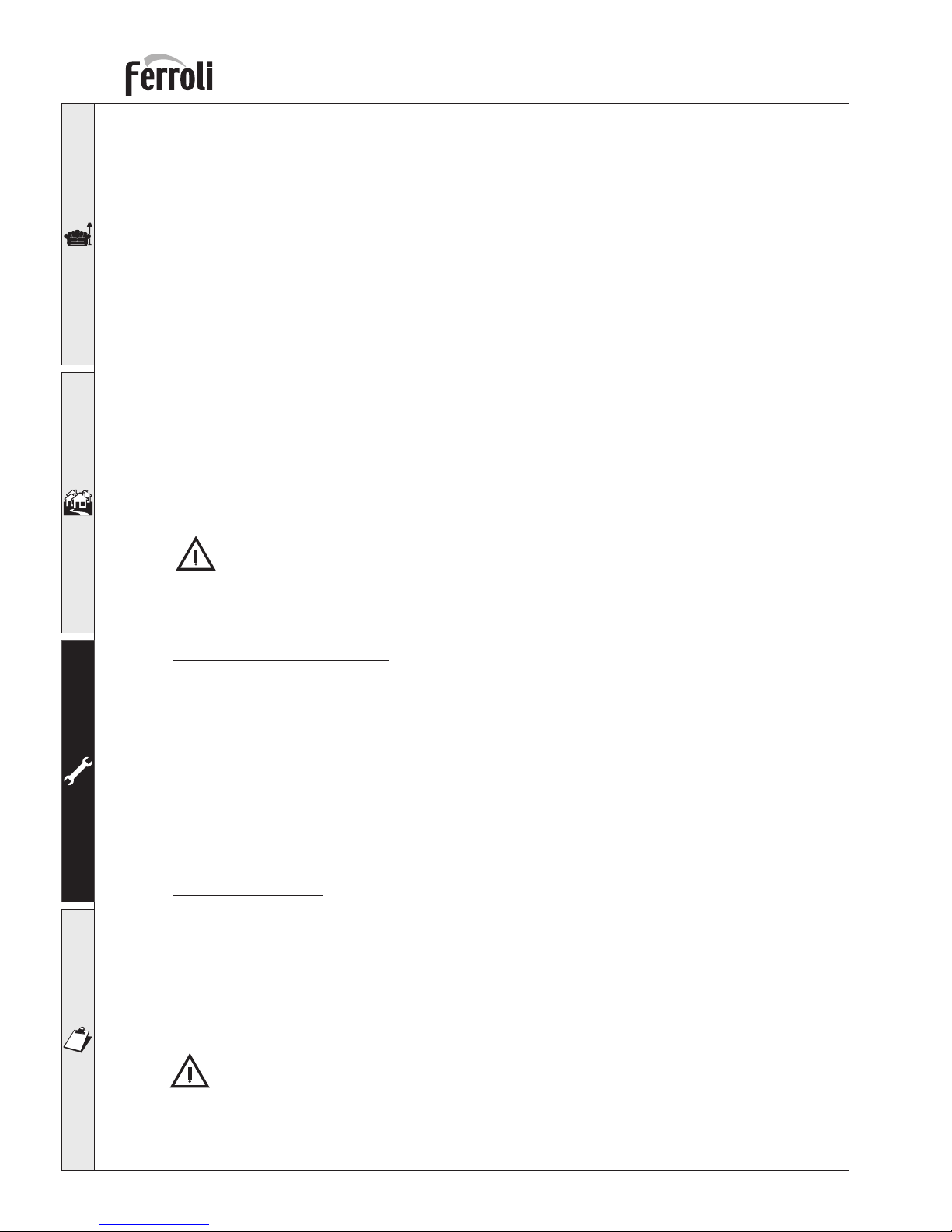
Adjusting the maximum heating output
This adjustment may only be performed electronically using the adjustment potentiometer “P3”, starting with a system temperature less than the maximum of the setting thermostat (system temperature
50 ¸ 60°C).
Connect a suitable pressure gauge to the pressure test point located downstream of the gas valve; turn
the temperature control knob to the maximum value, then adjust the pressure to the value required,
using the pressure-output diagram in the chapter on technical specifications. Once this operation has
been completed, turn the burner on and off 2 or 3 times using the thermostat and check that the pressure
remains stable at the set value. If not, a further fine adjustment must be performed, until the pressure
remains stable at the set value. When the burner is ignited to check the calibration pressure, turn the
setting thermostat knob to the maximum value, otherwise the procedure will be incorrect.
Adjusting the heating ∆t by varying the flow-rate/discharge head of the pump
The thermal head, ∆t (difference between the central heating outlet and inlet temperature) must be less
than 20°C. This is checked by varying the flow-rate and discharge head of the pump, using the speed
control (or switch) on the pump itself. Note that increasing the speed of the pump decreases the ∆t,
and vice-versa.
3.2 Commissioning
The appliance must only be commissioned for use by Qualified Personnel, such as personnel from
our sales organisation or the local Customer Service Centre.
Checks to be performed during the first ignition, and after all maintenance operations which
may have required the disconnection from the systems or intervention on the safety devices or
parts of the boiler:
Before igniting the boiler:
• Open any on-off valves between the boiler and systems.
• Check the gas system for tightness, proceeding with care and using a soapy water solution to find
any leaks from the connections.
• Fill the system with water and ensure that the air contained in the boiler and the system has been
completely vented, by opening the air vent valve on the boiler and any vent valves in the system.
• Check that there are no water leaks in the heating system, in the domestic hot water circuits, in the
connections or in the boiler.
• Check the correct connection of the electrical system.
• Check that the appliance is properly earthed.
• Check that the pressure value and gas rate for the heating system are correct.
• Check that there are no inflammable liquids or materials in the immediate vicinity of the boiler.
Igniting the boiler
• Open the gas cock upstream of the boiler.
• Vent the air in the pipe upstream from the gas valve.
• Close any switches or insert any plugs upstream of the boiler
• Place the main switch in the ON position.
• Place knob “B” in the Winter position to a value higher than 50°C and set the room thermostat, if
fitted, to the required temperature value. At this point, the burner will ignite and the boiler will start
operating automatically, managed by its control and safety devices.
If, after correctly having performed the ignition operations, the burners do not ignite and the shutdown warning light is on, wait around 15 seconds and then turn knob “A” (Fig. 1) to the RESET
position and release it. The control unit will be reset and will repeat the ignition cycle. If, after a
number of attempts, the burners do not ignite, refer to the paragraph “Troubleshooting”.
Page 15
15
Tempra 30 O
In the case of power failures while the boiler is in operation, the burners will switch off. When
mains power returns, the burners will automatically re-ignite.
Checks during operation
• Check the fuel circuit and the water system for tightness.
• Check the efficiency of the flues and air-flue gas pipes during the operation of the boiler.
• Check that the water circulation between the boiler and the systems is correct.
• Ensure that the gas valve modulates correctly both in the central heating phase and the production
of domestic hot water.
• Check the correct ignition of the boiler, by performing a series of ignition and shut-down tests using
the room thermostat or the remote control.
• Ensure that the consumption of fuel indicated by the counter corresponds to the values shown in the
technical data table in Chap. 4.
• Check that there is the correct flow rate of domestic hot water with the ∆t declared in the table: do
not rely on measurements effected using empirical systems. The measurements should be made using
special instruments at a point as close as possible to the boiler, considering the dispersion of heat
from the piping.
• Ensure that without the request for heating the burner ignites correctly when opening a hot water
tap. Check that during operation in central heating mode, when opening a hot water tap, the heating
pump switches off, the domestic hot water pump starts and there is regular production of domestic
hot water.
Shut-down
Close the gas cock upstream of the boiler and disconnect the appliance from the mains power supply.
For extended periods of inactivity during the winter months, in order to avoid damage due to
freezing, all the water should be drained from the boiler, both the domestic hot water and the
central heating system; alternatively, drain only the domestic hot water and place the special
antifreeze fluid in the central heating system.
3.3 Maintenance
The following operations must only be performed by Qualified Personnel, such as personnel from
our sales organisation or local Customer Service Centre.
Seasonal checks on the boiler and the stack
The following checks should be made on the appliance at least once a year:
• The control and safety devices (gas valve, flow-meter, thermostats, etc.) must be working properly.
• The pipes and the air-flue gas terminals must be free of obstacles and not have any leaks.
• The gas and water systems must be perfectly tight.
• The burner and the heat exchanger must be clean. Follow the instructions in the next paragraph.
• The electrodes must be free of deposits and positioned correctly.
• The pressure of the water in the system when cold must be around 1 bar; if not, restore this value.
• The expansion vessel must be full.
• The gas rate and the pressure must correspond to the values indicated in the corresponding tables.
• The circulation pumps must not be blocked.
Page 16
16
Tempra 30 O
Cleaning the boiler and the burner
The body and the burner must not be cleaned using chemical products or steel brushes. Special care
must be taken to ensure all the systems relating to the sealed compartment are tight (gaskets, cable
glands, etc..), to
avoid air leaks which, causing a drop in the pressure inside in chamber, may activate the differential
pressure switch and thus shut-down the boiler. Special attention must also be paid, after all the operations have been completed, to checking and performing all the ignition phases and operation of the
thermostats, gas valve and circulation pump.
After these checks, ensure that there are no
gas leaks.
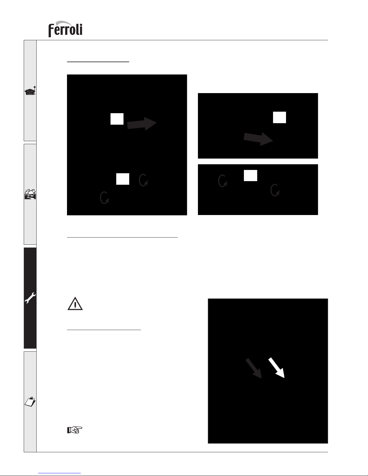
Analysis of combustion
Two test points are installed inside the boiler, one for
the flue gases and the other for the intake air.
To make the measurements, proceed as follows:
1) Remove the boiler casing
2) Open the air and flue gas sample points in the sealed
compartment;
3) Insert the probes as far as possible;
4) Open a hot water tap;
5) Adjust the domestic hot water temperature to the
maximum setting.
6) Wait 10-15 minutes to allow the boiler to reach stable
operating conditions*
7) Make the measurements.
Analysis performed when the boiler is not in
stable operating conditions may lead to errors
in measurement.
Opening the casing
Follow the indications shown in the figure to open the casing.
4
3
1
2
Air
Flue gases
Page 17
17
Tempra 30 O
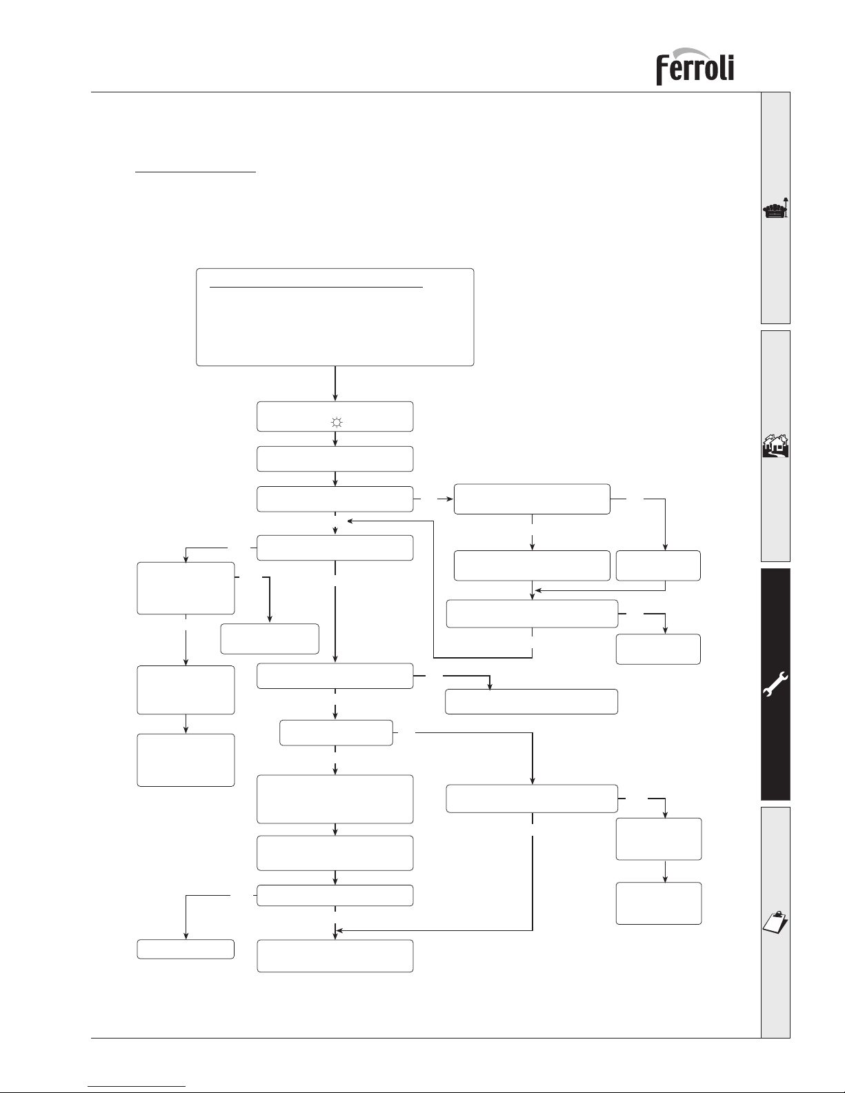
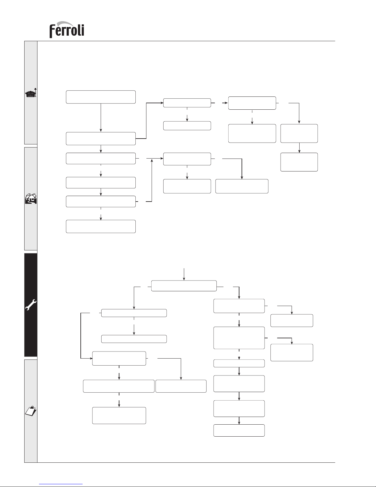
3.4 Troubleshooting
Troubleshooting
Flow Diagram 1
Checking Power Supply-System Pressure and Anti-freeze Protection
Is LED5 on?
Put main switch to on
CH Selector to
Summer
position
Is 240V present across
terminals X1-1 X1-2?
Check and if necessary
replace 2A fuse
YES
Is LED5 ON now?
Repair external
wiring fault
NO NO
Replace
main board
NO
YES
Is LED5 flashing?
YES
Water pressure
is not set
between
1 - 1,5 bar?
YES
Set pressure to
1 - 1,5 bar
Check water
pressure
switch wiring
connection
NO
Does fan run at full speed?
NO
Go to CHART 2
NO
YES
Does CH Pump run?
If the boiler temperature
is less than 5°C
frost protection is activated
Disconnect
CH flowtemp sensor
Has fan speed stopped?
Check and if necessary
replace main board
NO
YES
Check and if
necessary
replace water
pressure switch
Chek the following carefully before starting
Gas supply is turned on, is adequate and purged
Electricity supply is turned on
Polarity is correct
CH pressure is set between 1 - 1,5 bar
CH pump spins freely
YES
NO
Is Relay RY101 switch on?
Check and if
necessary
replace pump
YES
NO
Check pump
wiring
connection
YES
Go to CHART 2
Page 18
18
Tempra 30 O
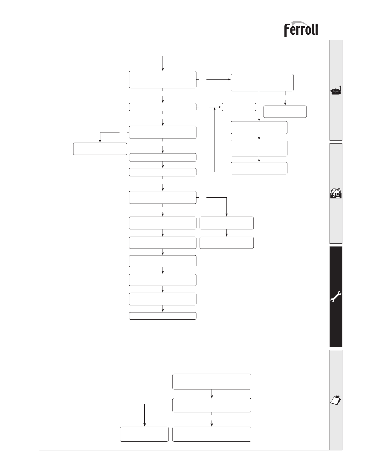
Flow diagram 2
Checking Central Heating Operation
Flow diagram 3
Checking the Fan/Flue Gas Circuit
Wait 2 minutes
Put CH temperature selector
to maximum
Ensure external controls
are calling for heat
Is LED4 flashing?
Does CH pump run?
YES
YES
Go to chart 3
Is relay RY101
switch on
Check and if
necessary replace
main board
NO
Is LED4 flashing?
Check and if is necessary
replace main board
YES
NO
Is relay RY100
switch on
NO
YES
Go to chart 3
NO
Check
limit thermostat
YES
Check pump
wiring
connection
NO
Check and if
necessary
replace pump
Does fan run?
Is relay RY100 switch ON?
NO
Go to charts 2
NO
Is 230V present across
fan terminals?
YES
Check air pressure
switch wiring connection in N.O.
NO
Check and if
necessary replace
air pressure switch
NO
Check and if
necessary replace fan
YES
Is air pressure switch
activated?
YES
NO
Check and if
necessary replace
air pressure switch
YES
Differential air pressure
across the air pressure
switch is greater than
180 Pascal?
Go to chart 5
YES
NO
Check and clean fan
Check flue and air
intake are correct
and clean
Check Venturi and
air pressure switch
tubes are clean
Check restrictor
is correct
Page 19
19
Tempra 30 O
Flow diagram 4
Checking Ignition
Flow diagram 5
Checking Domestic Hot Water Modulation
Does burner
flame modulate?
Normal operation
carry out
YES
NO
Boiler operated
on central heating mode
Check CH sensor
and replace it if necessary
Is LED1 light on?
Does sparking start
at burner?
Does burner light?
YES
Is LED2 on
after 10 seconds?
NO
YES
Go to chart 4
Reset lockout
YES
Does burner light now?
Is flame present before
lockout condition?
NO
YES
NO
Check and if necessary
replace safety thermostat
Check electrodes and
leads for damage
and correct connection
Check and if necessary
replace P.C.B.
Adjust with P4 ignition
burner pressure
Check and if necessary
clean burner
Check and if necessary
clean injectors
Check and if necessary
clean flame electrode
Check right position
of spark electrode
Check wires
Check gas supply
is live and purged
Check and if necessary
replace gas valve
NO
YES
Check and if necessary
replace P.C.B.
NO
Is LED2 on
without
the boiler sparking
YES NO
Re-check
air pressure switch
Page 20
20
Tempra 30 O
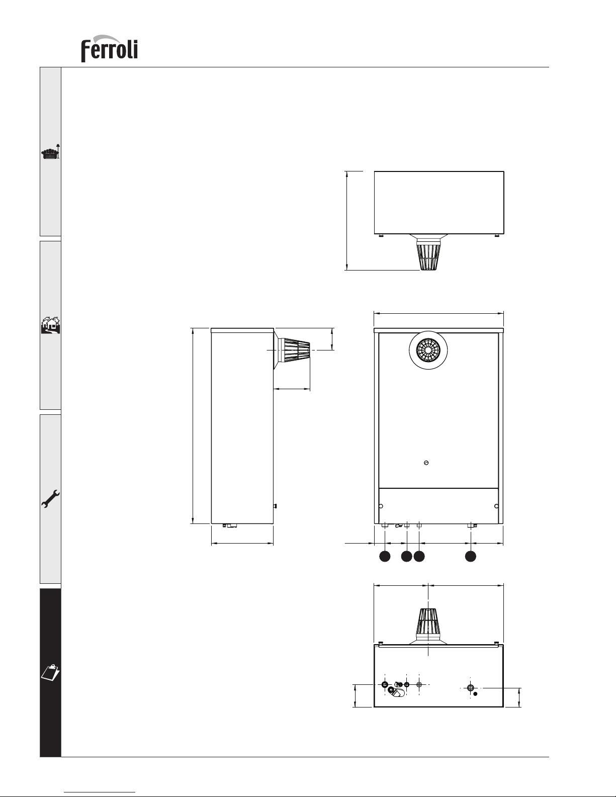
4. CHARACTERISTICS AND TECHNICAL SPECIFICATIONS
4.1 Dimensions and fittings
fig. 7
Key
1 CH flow
2 Filling cock
3 Gas inlet
4 CH return
Top View
Bottom View
99
85
428
850
96
158
270
236,5
326,5
141223,5
54
95
46,5
1 2 3 4
560
Page 21
21
Tempra 30 O
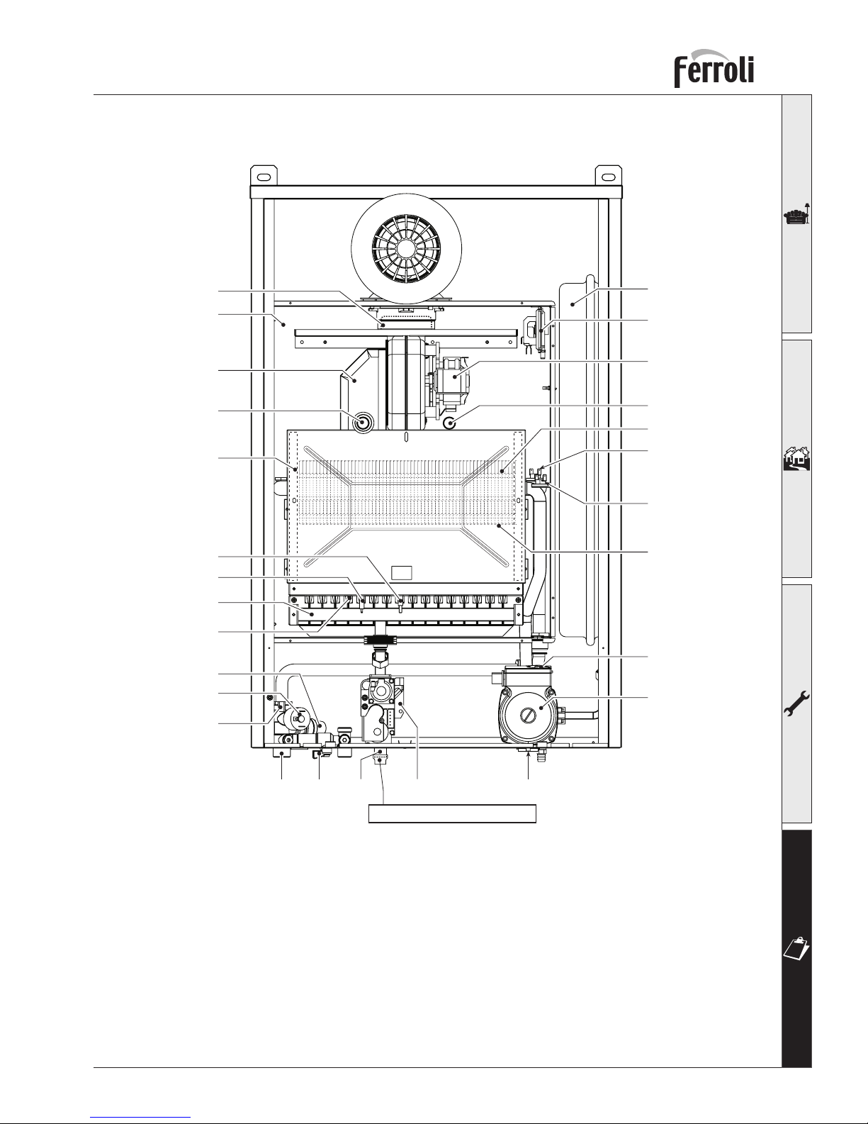
4.2 Overall view and main components
Key
5 Sealed compartment
7 Gas inlet
10 Central heating outlet
11 Central heating inlet
14 Safety valve
16 Fan
19 Combustion chamber
20 Burner assembly
21 Main nozzle
22 Burner
26 Combustion chamber
insulation
fig. 8
16
56
43
32
28
90
91
5
10
49
50
71174 44
14
19
187
22
82
81
36
20-21
26
27
114
34
Threaded adapter ISO 7-1
27 Copper heat exchanger
28 Flue collector from heat
excanger
32 Central heating pump
34 Central heating temperature
sensor
36 Automatic air vent
43 Air pressure switch
44 Gas valve
49 Safety thermostat
50 Central heating limit
thermostat
56 Expansion vessel
74 Filling cock
81 Ignition electrode
82 Detection electrode
90 Flue outlet pressure test point
91 Air outlet pressure test point
114 Water pressure switch
187 Flue gas restrictor
Page 22
22
Tempra 30 O
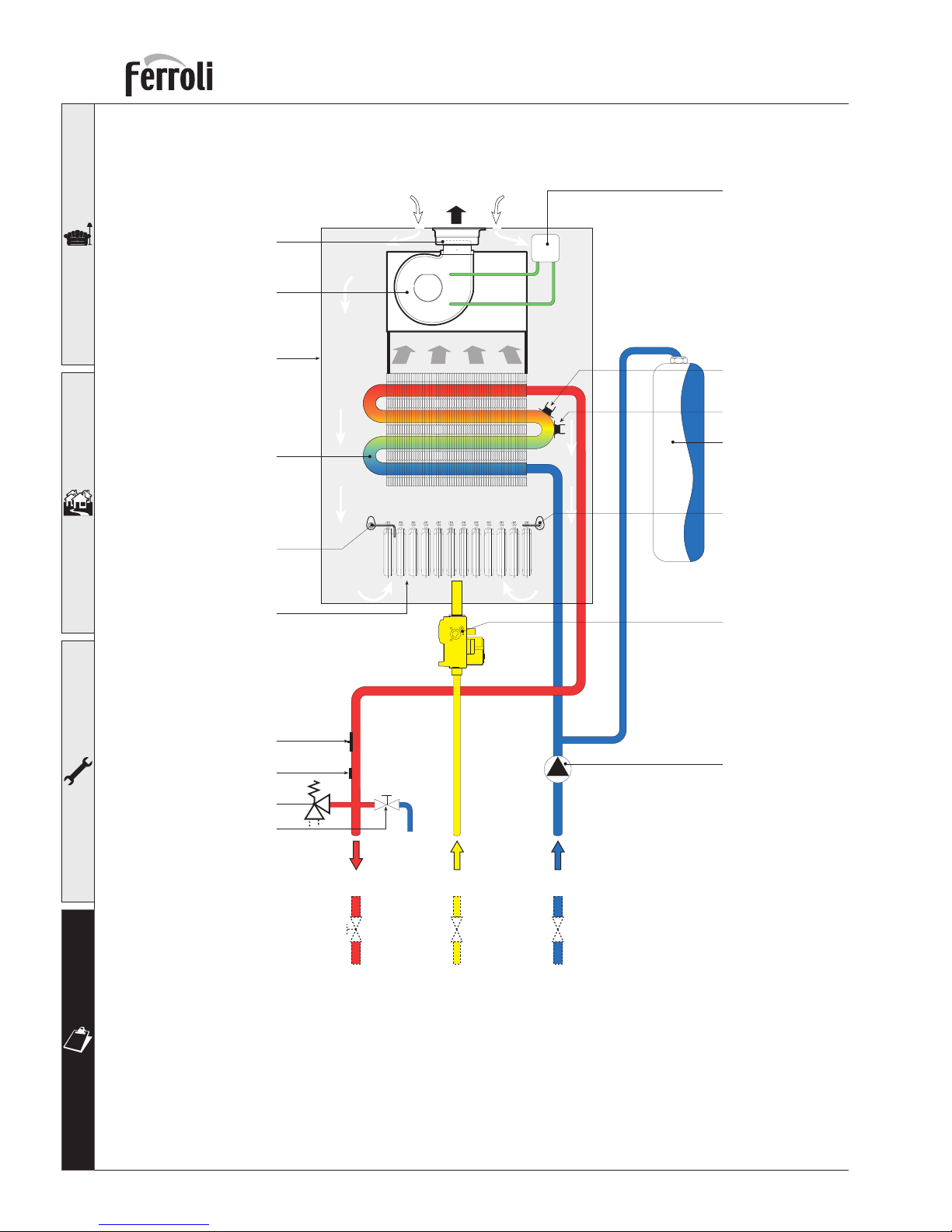
4.3 Hydraulic diagram
fig. 9
43
50
56
81
44
32
20
82
222
5
29-187
16
74
14
114
34
11710
-
+
49
Key
5 Sealed compartment
7 Gas inlet
10 Central heating outlet
11 Central heating inlet
16 Fan
20 Burner assembly
29 Flue gas outlet manifold
32 Central heating pump
34 Central heating temp. sensor
43 Air pressure switch
44 Gas valve
49 Safety thermostat
50 Central heating limit
thermostat
56 Expansion vessel
74 Filling cock system
81 Ignition electrode
82 Detection electrode
187 Flue gas restrictor
222 Copper heat exchanger
Page 23
23
Tempra 30 O
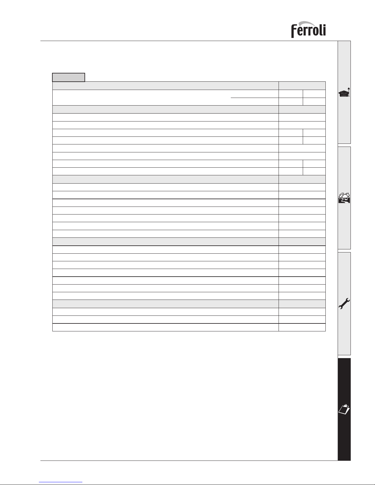
4.4 Technical data table
Gas supply Pmax Pmin
Power Output
Output Pmax Pmin
Universal LPG kW 27,9 15,6
Natural Gas kW 30 17
Dimensions, weights, fittings
Depth mm 272
Width mm 460
Height mm 760
Hot water capacity litres 1,7
Expansion vessel pre-fill pressure kPa 100
Expansion vessel capacity litres 10
Minimum central heating operating pressure kPa 80
Maximum central heating operating pressure kPa 300
Maximum central heating operating temperature °C 100
Index of protection IP X5D
Power supply
Power supply voltage/frequency V-Hz 240-50/60
Max Power Absorbed W 125
Central heating system fittings inches 3/4
System filling fittings inches 1/2
Gas system fittings inches 1/2
Weight with packaging kg 51
Central heating
Natural gas consumption MJ/h 132 77,6
Table 11
Main injectores, Natural Gas (G20) mm 16 x 1,35
Burner pressure, Natural Gas (G20) kPa 0,83 0,25
Inlet pressure, Natural Gas (G20) kPa 1,13
LPG gas rate consumption MJ/h 120 69,7
Main nozzles, LPG mm 16 x 0,77
Burner pressure, LPG kPa 2,50 0,70
Supply pressure, LPG kPa 2,75
Safety valve kPa 300
Page 24
24
Tempra 30 O
4.5 Diagrams
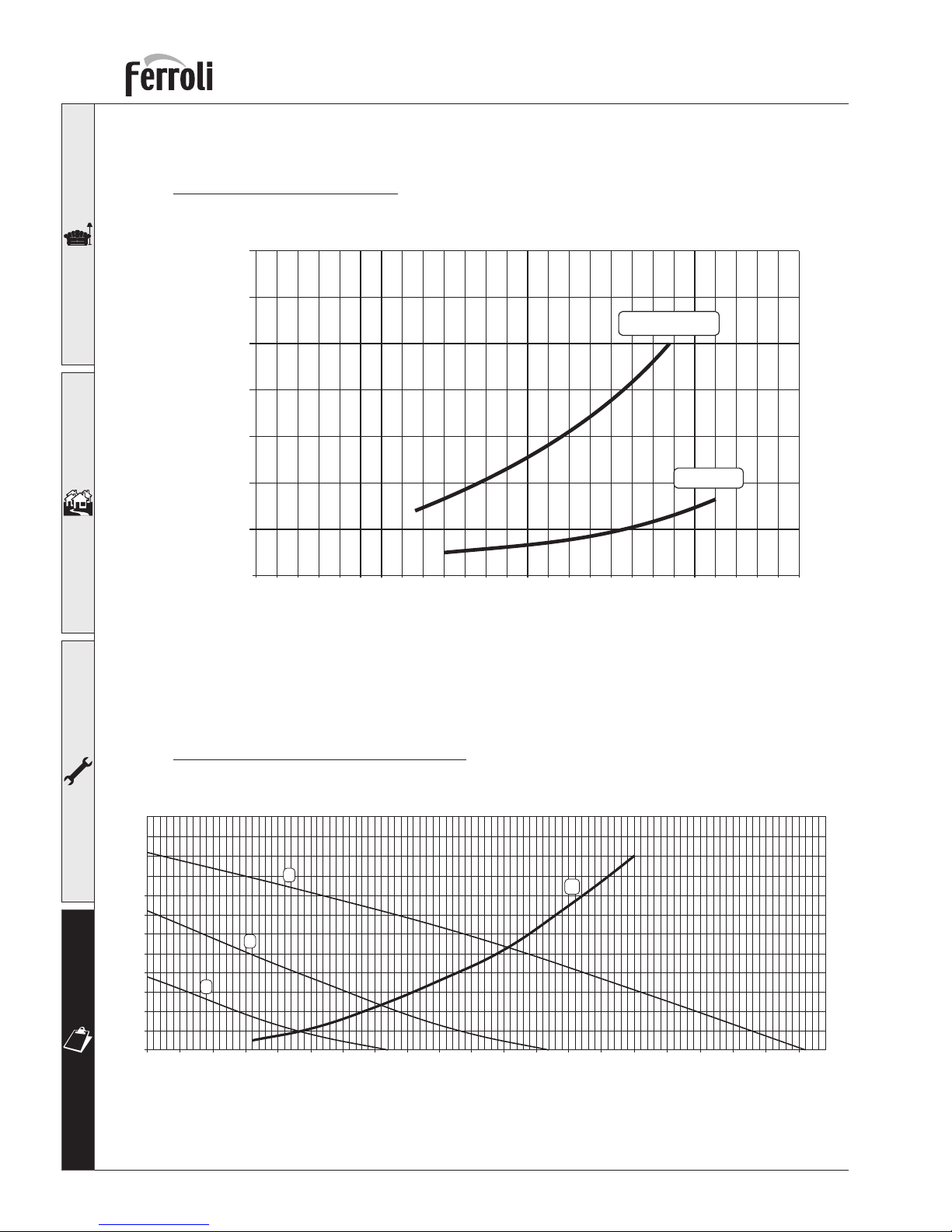
Pressure - output diagrams
Legenda
1 - 2 - 3 = Pump switch positions
A = Boiler pressure drop
Discharge head available to system
fig. 10
fig. 11
kW
kPa
18 19 20 21 22 23
0,5
1,0
1,5
2,0
2,5
3,0
3,5
9101112 13 14 15 16 178
24 25 26 27 28 29 30 31 32 33 34
Universal LP Gas
Natural Gas
m
C.A.
m3/h
0
0,5
1
1,5
2
2,5
3
3,5
4
0,6 0,8 1 1,2 1,4 1,6 1,8 2 2,2 2,4 2,6
4,5
5
5,5
6
2,8 3 3,2 3,4 3,6 3,8 40,40,20
A
3
2
1
Page 25
25
Tempra 30 O
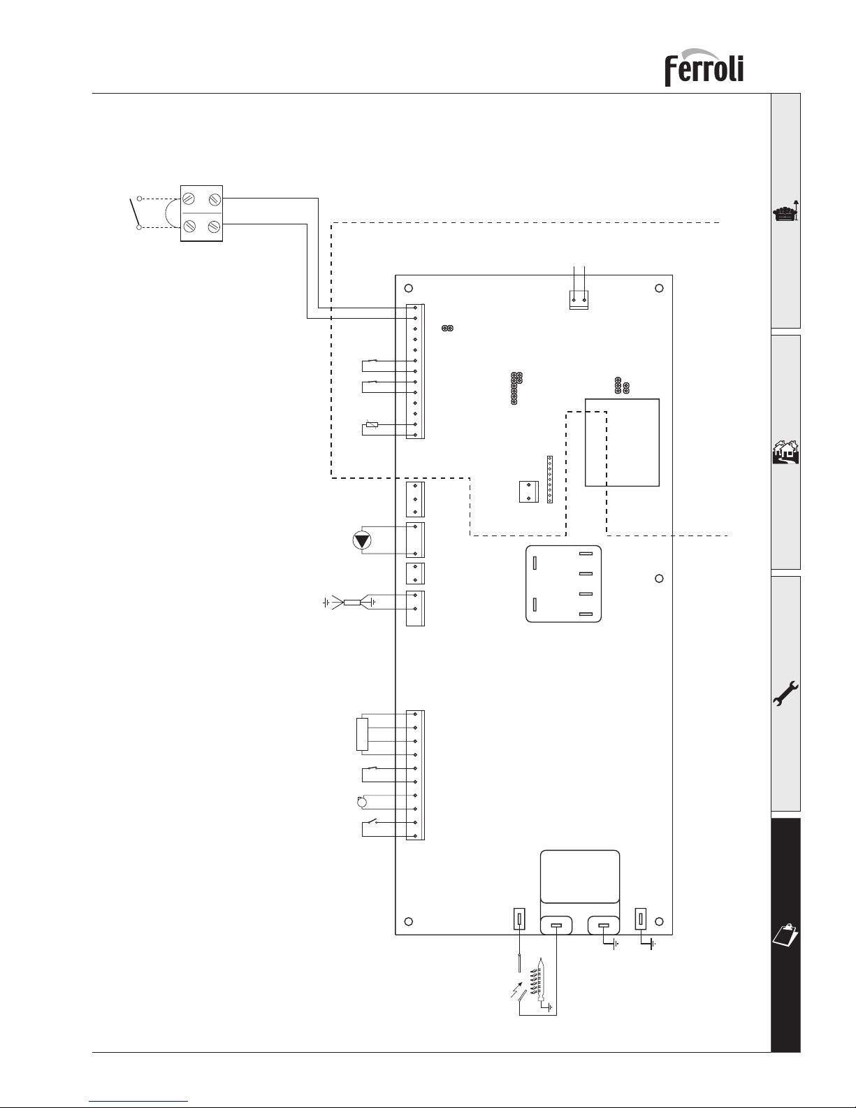
4.6 Wiring diagram
fig. 12
Key
16 Fan
32 Central heating pump
34 Central heating temperature sensor
43 Air pressure switch
44 Gas valve
49 Safety thermostat
50 Limit thermostat
X6
X1
X2 X3
X4
12121312345678910 12345678910111213
21
X5
TEST
X12
12
123456789
X10
W
O
V
R
X8
X7
81 82
PMF03F
JP02
JP01
JP03
Nat/LPG
X11
240V 24V
240V
24V
BR
Blue
BR
Blue
BR
Blue
MV1
MV2
MV3
MV4
Blue
BR
Blue
BR
BR
Blue
R
R
O
O
Blue
BR
BL
BL
BL
Y/G
Y/G
BL
X9
123
Blue
BR
W
W
101
LN
21
72
98
5011 434
32
44491643
175
72 Room thermostat (Optional)
81 Ignition electrode
82 Detection electrode
98 Switch
101 Electronic board
114 Water pressure switch
175 Transformer
Page 26

Page 27

Page 28

FERROLI S.p.A.
Via Ritonda 78/a
37047 San Bonifacio - Verona - ITALY
www.ferroli.it
 Loading...