

Page 1
INSTALLATION, USE AND
MAINTENANCE
INSTRUCTIONS
INSTRUCTIONS POUR
L’INSTALLATION
L’UTILISATION ET
L’ENTRETIEN
S.p.A.
SUN
HEA TING OIL
BURNER
BRULEUR À
FUEL
Page 2

Index page
General information - Technical and dimensional features................................................................ 3
Main parts - Operative range of the burner ........................................................................................ 4
Electrical connections ........................................................................................................................ 5
Heating oil fuelling line ....................................................................................................................... 6
Boiler assembly - Pump pressure regulation ..................................................................................... 7
Choosing the injector ......................................................................................................................... 8
Head regulation and air flow rate adjustment - Example of combustion regulation
Position of electrodes-baffle............................................................................................................... 9
Setting at work - Work cycle...............................................................................................................10
Maintenance - Demounting and servicing the burner ........................................................................ 11
Troubleshooting .................................................................................................................................12
Components.......................................................................................................................................13
List components ................................................................................................................................. 14
Page 3
S.p.A.
GENERAL INFORMATION
Ferroli is proud to present this series of heating oil burners for domestic boilers, with thermal power ratings
of between 13,3 and 58,1 kW. A compact and attractive design make these burners fit for use with the
majority of the boilers currently available on the market.
Use of modern technologies has enabled Ferroli to produce these new appliances able to optmize the
air-fuel mixing function. This achieves high efficiency, low degrees of CO and NOx together with a very
silent flame.
Here are the more important technical features:
- Fine adjustment of the position of the combustion head in relation to the nozzle by means of a
micrometric screw.
- Accurate air adjustment on the intake.
- Air lock with gravity closing when the burner stops. This notably limits heat dispersions when the boiler
is on hold.
- Burner is complete with a preheater on the nozzle line. This improves combustion and ensures prompt
ignition after lengthy periods at a standstill during the colder season and when paraffinic heating oil is
used.
- The inspection and servicing operations are very convenient for all models.
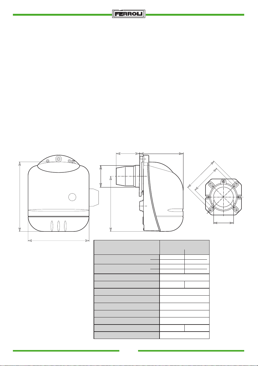
TECHNICAL AND DIMENSIONAL FEATURES
96
0
180
286
Fig. 1
250
Ø90
227
Type
Fuel Flow Rate kg/h
Thermal Power Rating kW
Fan
Preheater
Fuel Nozzle
Ignition trasformer
Motor
Fuel
SUN
G.6 R G.6
min.
1,12
4,90
max.
min.
13,3
58,1
max.
146-48 rsx 40 pale
110 W
Øe 64 - Øi 16 nr. 6 tagli
2x7 kV 40 mA
70W 0.6A 2735 g/min
Heating oil max 20 °C 1.5 E
220 - 240V 50HzEl. Power Supply
220 WInput
SUN
IP40Prot. Class
Ø 170
1,8
4,9
21,3
58,1
/
170 W
Ø 140
Ø91
3
Page 4
S.p.A.
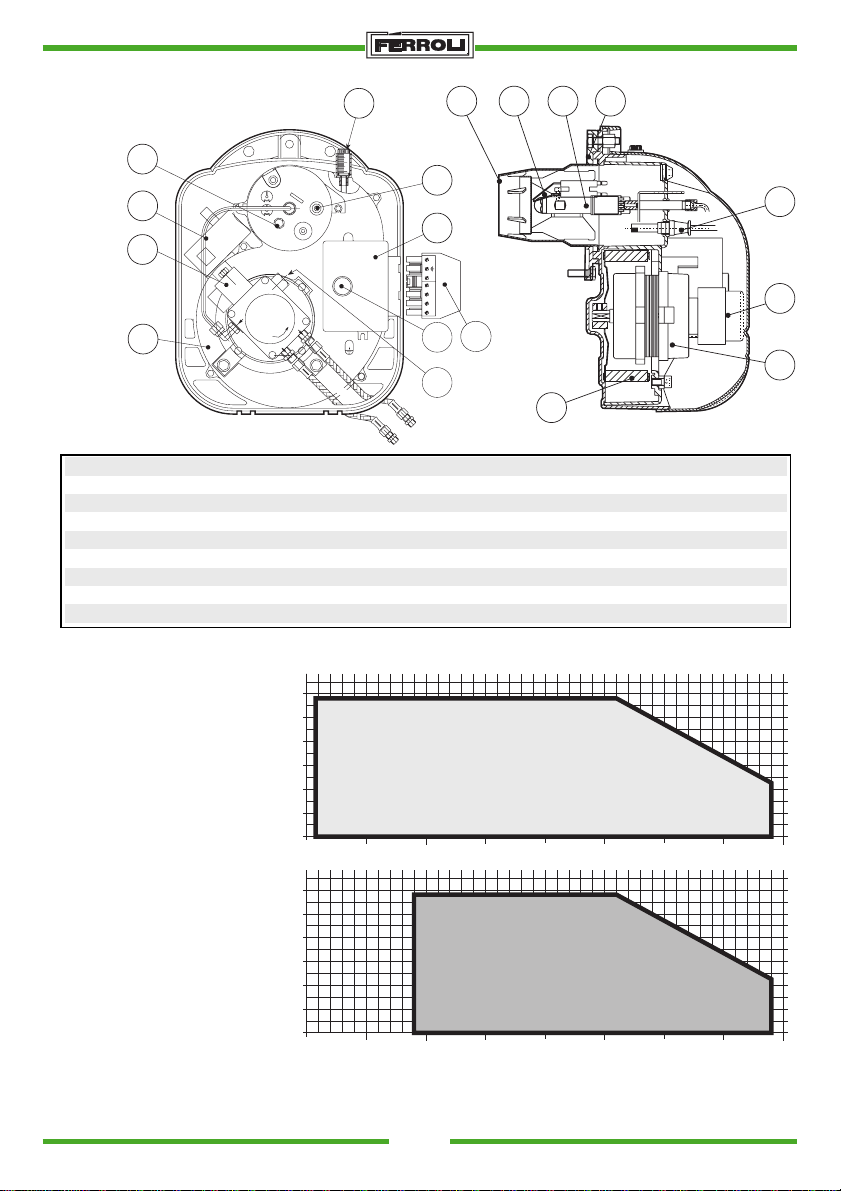
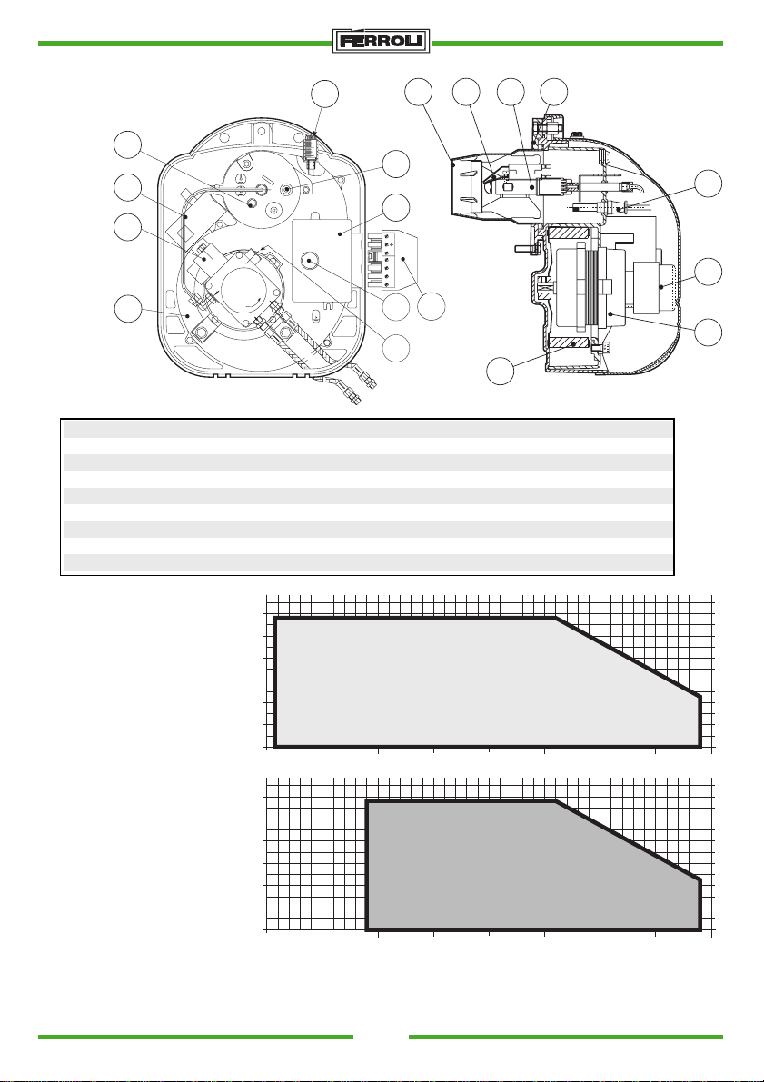
MAIN PARTS
16
8
3
P
V
4
Key
1 Heating oil pump
2 Motor
3 Electromagnetic valve
4 Burner unit
5 Release button
6 Mechanism
7 Photoresistance
8 Ignition transformer
9 Burner coupling flange
OPERATIVE RANGE OF THE BURNER
13
0
5
10
15
20
12 11 10 9
18
6
14
5
17
Fig. 2
10 Injector line with preheater
11 Ignition electrodes
12 Nozzle
13 Air lock adjuster screw
14 Spina allacciamento elettrico
15 Fan
16 Combustion head adjustment
17 Pump pressure adjustment
18 Pressure tap
15
7
1
2
0.6
0.5
0.4
0.3
∆p mbar
0.2
0.1
0
kg/h
1
0.6
0.5
0.4
0.3
∆p mbar
0.2
0.1
Fig. 3
kg/h
0
1
Pressure in combustion chamber ∆p mbar
Heating oil flow rate Kg/h
4
1.5
1.5
SUN G.6 R
2.0 5.04.54.03.53.02.5
SUN G.6
2.0 5.04.54.03.53.02.5
SUN
Page 5
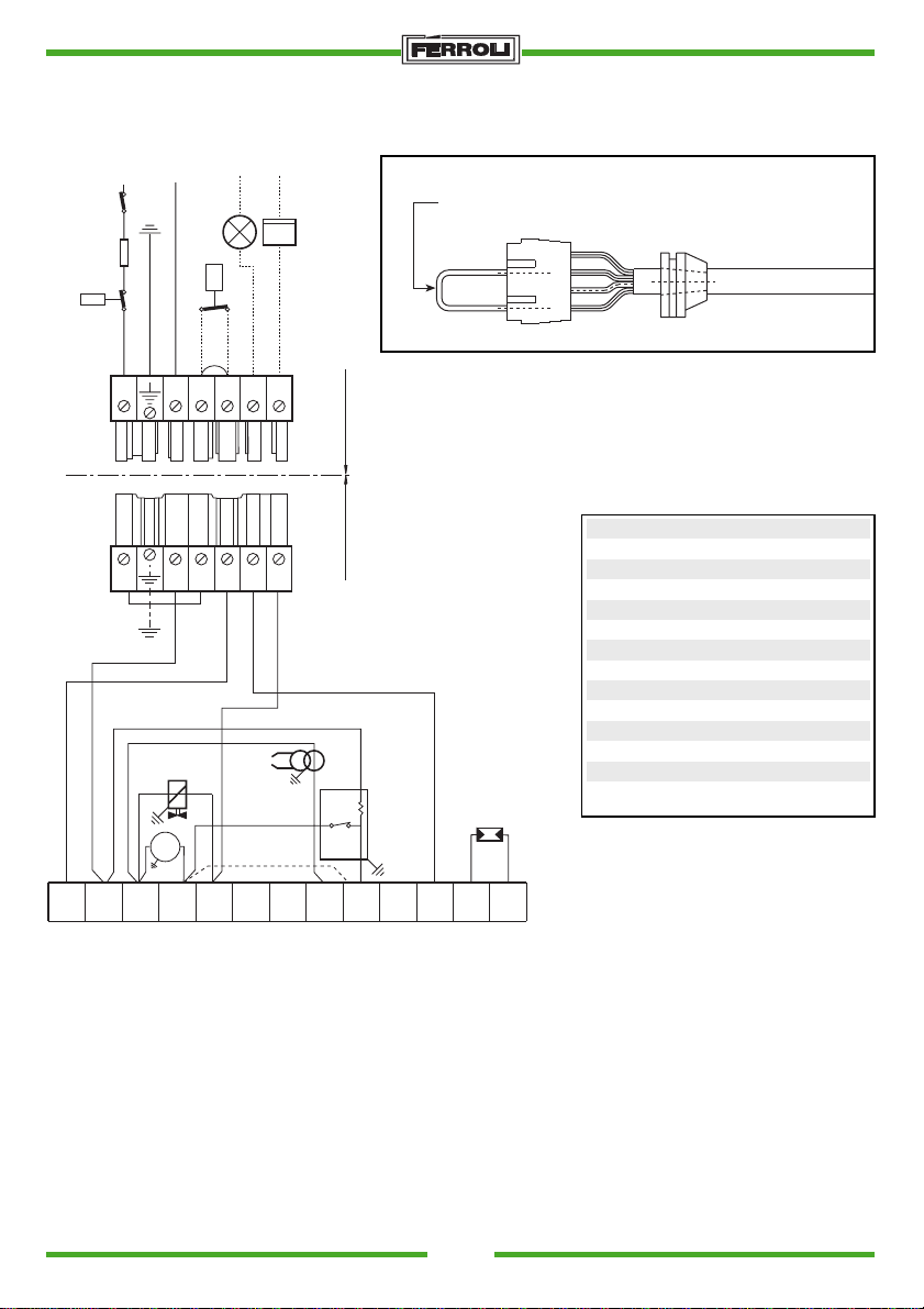
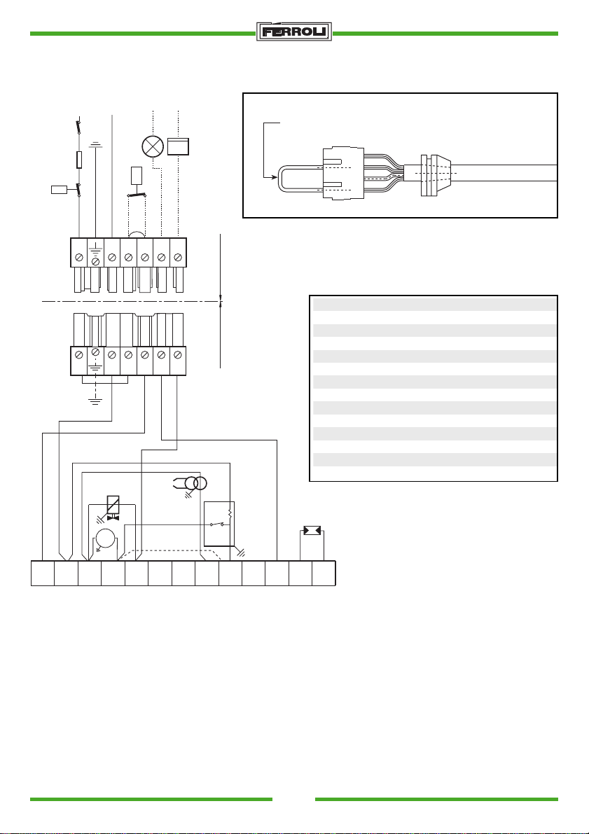
ELECTRICAL CONNECTIONS
NNNPh
IG
F
TS
L1 N T1 T2 S3 B4
LS
TA - TC
CO
w
h
S.p.A.
PREHEATER CONNECTION
Connection for without
preheater version
GN
M
B
N
4321
Preheater cable
PB SC
T2
M
1~
MB
T1
VE
S3 B4
TR
PR
FR
N
Tm
L1
12 34567891011122
Fig. 4
The following electrical connections are at the installer’s charge:
- power supply line
- thermostat line
- possible shutdown indicator light and/or hour meter
Key
CO Hour counter
F Fuse
FR Photoelectric resistance
IG Main switch
LS Safety light
MB Burner motor
PB Burner tap
PR Preheater (G6R only)
SC Plug
TA-TC Boiler - room thermostat
TR Ignition transformer
TS Safety thermostat
Tm Minimum rating thermostat
VE Electromagnetic valve
Attention
- do not switch the neutral and phase wires
- always install a good ground connection
SUN
5
Page 6
S.p.A.
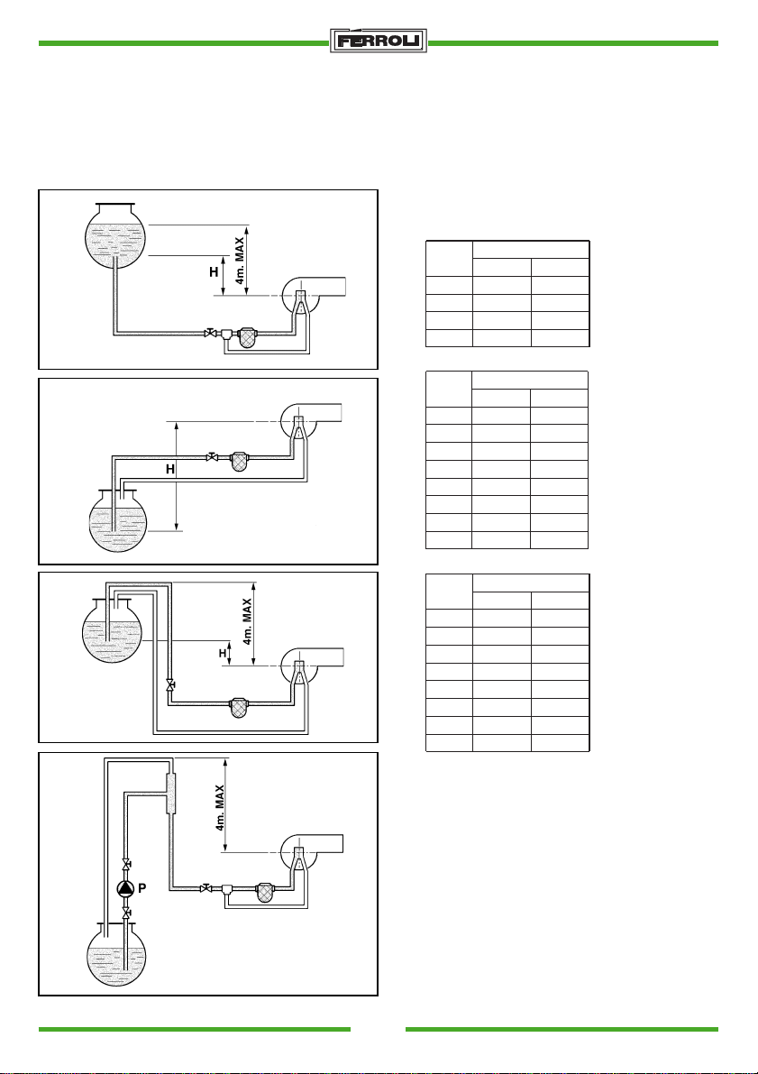
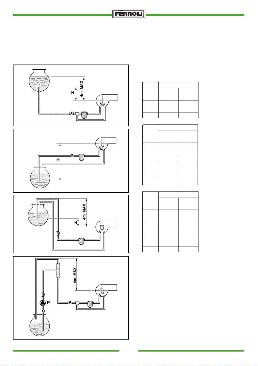
HEATING OIL FUELLING LINE
Attention: Before starting the burner, check that the fuel return pipe is not clogged. Excessive over-
pressure would break the pump retaining component.
Install a filter on the fuel supply line.
A
Fig. 5a
B
Fig. 5b
C
Fig. 5c
D
(m)
0.5
1.0
1.5
2.0
(m)
0.0
0.5
1.0
1.5
2.0
2.5
3.0
3.5
(m)
0.0
0.5
1.0
1.5
2.0
2.5
3.0
3.5
H
H
H
L (m)
Øi 8 mm. Øi 10 mm.
10
20
40
60
Øi 8 mm. Øi 10 mm.
25 60
21
18
15
12
10
8
6
Øi 8 mm. Øi 10 mm.
25 60
21
18
15
12
10
8
6
20
40
80
100
L (m)
50
44
38
32
26
20
16
L (m)
50
44
38
32
26
20
16
HYDRAULIC CIRCUITS
A Gravity supply
B Suction supply
C Siphoned supply
D Ring supply
6
Fig. 5d
Nota: Add 0.25 meters to the pipe length for each
elbow or gate valve (load losses).
L Total length of intake pipe including vertical
sections
H Difference in level
Øi Inner pipe diameter
SUN
Page 7
S.p.A.
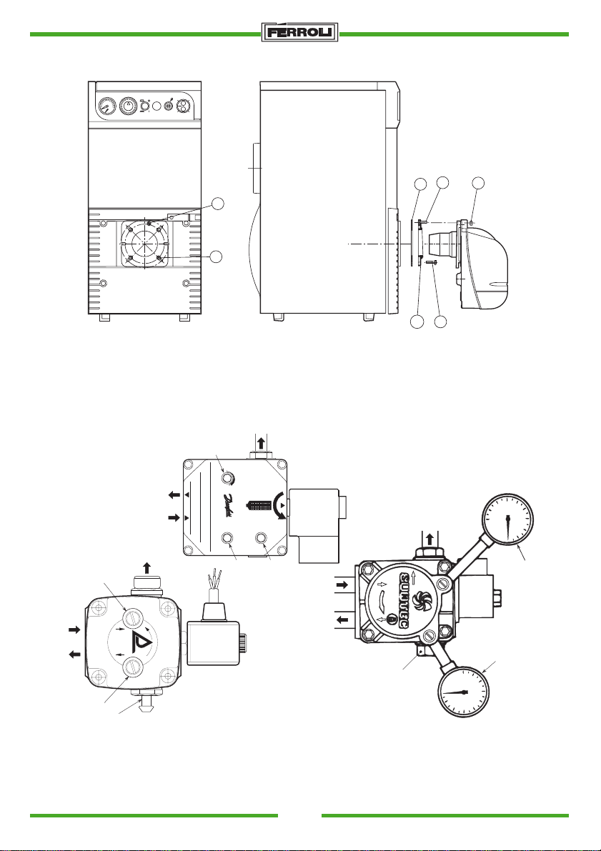
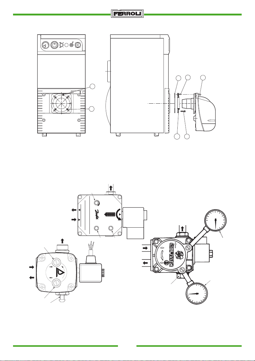
BOILER ASSEMBLY
6030
90
0
2
1
4
5
3
4
5
Fig. 6
-Insert screw 2 (m8x25) into flange 3
-Insert flange 3 into the boiler using the 5 screws (NR. 4 M8x30) with insulating seal 1 in between.
-Insert the burner into the boiler flange and fix it to screw 2 with nut 4.
PUMP PRESSURE REGULATION
3
6
Type BFP
NO.
DENMARK
1
MADE IN
2
V
P
3
54
5
V
230v. 50Hz.
VA. 11
1
DELTA
Cod. M81
DANFOSS BFP 11 R3
1
2
3
PV
4
2
4
DELTA VM1 RL2
6
P
Fig. 7
SUN
5
6
m h2O
SUNTEC AS
7
Page 8
S.p.A.
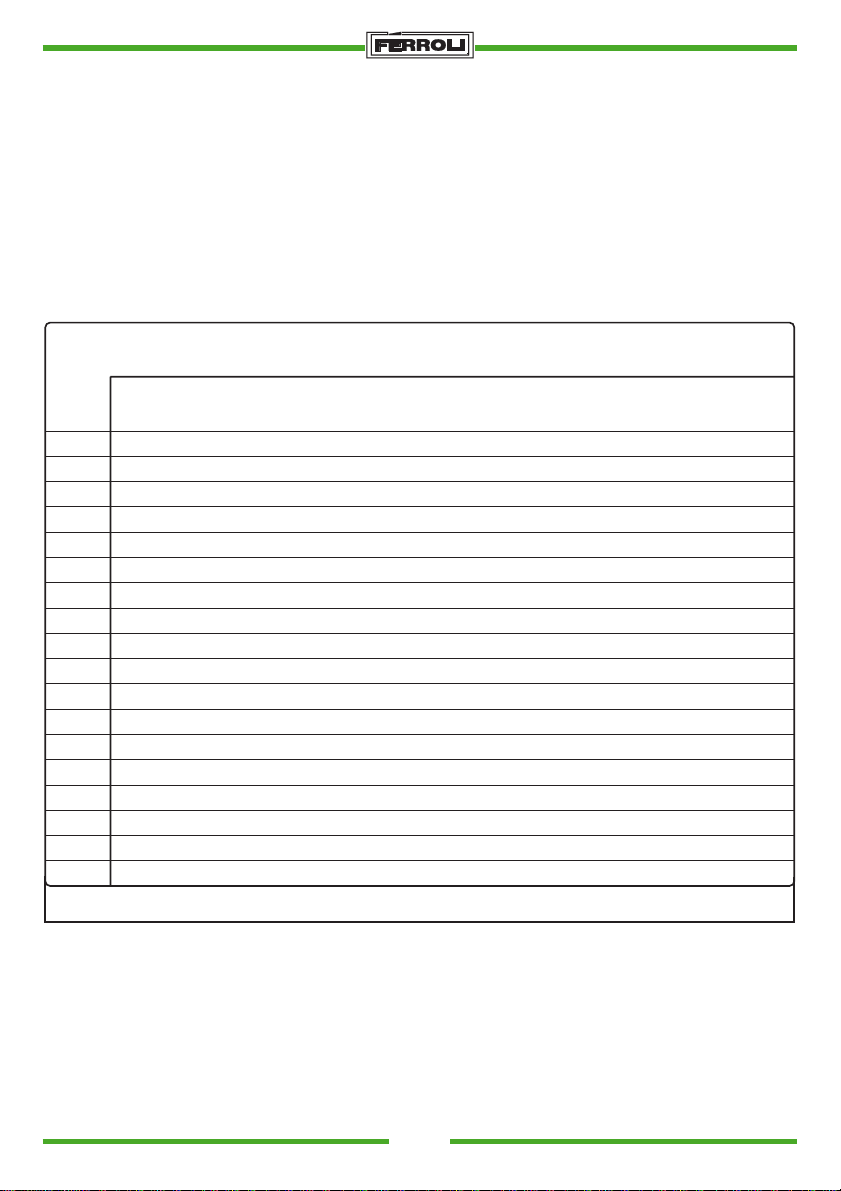
CHOOSING THE INJECTOR
The injector must be chosen according to the power rating of the boiler flue, remembering that heating
oil has a heat value (N.H.V.) of 10200 kcal/Kg. The chart gives the flow rate or consumption in Kg/h and
kW of heating oil according to the size of the injector (in GPH) and the pump pressure (in bar). When the
burner has a preheater, the effective capacity will be about 10% lower than the values in the chart.
Injector
G.P.H.
0,40
0,50
0,60
0,65
0,75
0,85
1,00
1,10
1,20
1,25
1,35
1,50
1,65
1,75
2,00
2,25
2,50
3,00
6
1,18
1,47
1,77
1,91
2,2
2,5
2,94
3,24
3,53
3,68
3,97
4,42
4,86
5,15
5,89
6,62
7,36
8,83
7
1,27
1,59
1,91
2,07
2,38
2,70
3,18
3,50
3,82
3,97
4,29
4,77
5,25
5,56
6,30
7,15
7,95
9,54
89
1,36
1,44
1,70
1,80
2,04
2,16
2,21
2,34
2,55
2,70
2,89
3,06
3,40
3,61
3,74
3,97
4,08
4,33
4,25
4,50
4,59
4,87
5,10
5,41
5,61
5,95
5,95
6,31
6,80
7,21
7,65
8,15
8,50
9,01
10,20
10,82
Flow rate at injector outlet kg/h
Pump pressure kg/cm
10
11
12
1,52
1,59
1,67
1 ,90
1,99
2,08
2,28
2,39
2,50
2,47
2,59
2,71
2,85
2,99
3,12
3,23
3,39
3,54
3,80
3,99
4,16
4,18
4,38
4,58
4,56
4,78
5,00
4,75
5,00
5,20
5,13
5,38
5,62
5,70
5,90
6,24
6,27
6,58
6,87
6,65
6,98
7,29
7,60
7,97
8,33
8,55
8,97
9,37
9,50
9,97
10,41
11,40
11,96
12,49
2
13
1,73
2,17
2,60
2,82
3,25
3,68
4,33
4,77
5,20
5,40
5,85
6,50
7,15
7,58
8,67
9,75
10,83
13,00
14
1,80
2,25
2,70
2,92
3,37
3,82
4,50
4,95
5,40
5,60
6,07
6,75
7,42
7,87
8,99
10,12
11,24
13,49
15 17
16
1,86
1,92
2,33
2,40
2,79
2,88
3,03
3,12
3,49
3,61
3,96
4,09
4,65
4,81
5,12
5,29
5,59
5,77
5,80
6,00
6,28
6,49
6,98
7,21
7,68
7,93
8,15
8,41
9,31
9,61
10,47
10,85
11,64
12,02
13,96
14,42
1,98
2,48
2,97
3,22
3,72
4,21
4,96
5,45
5,95
6,20
6,69
7,43
8,18
8,67
9,91
11,15
12,39
14,87
8
SUN
Page 9
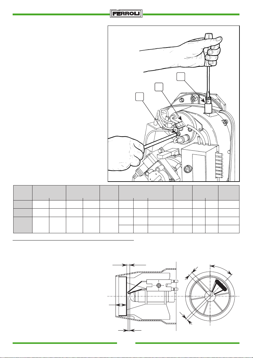
COMBUSTION HEAD AND AIR
C
A
B
DAMPER ADJUSTMENT (Fig. 8)
The combustion head is adjusted according to burner flow rate. To adjust, rotate
the adjustment screw (B) clockwise or
anticlockwise until the notch on the rod
“A” coincides with the indicator.
This modifies the position of the deflector in relation to the draught tube and consequently the passage of air.
The air flow rate is adjusted via screw “C”.
When the burner shuts down, the air
damper closes automatically.
EXAMPLE OF COMBUSTION REGULATION
The injector, pump pressure, combustion
head adjustment and air flow rate regulation must be established according to the
flow rate required by the boiler, as indicated in the following chart check combustion.
S.p.A.
Fig. 8
kcal/h
Burner
flow rate
Kg/h
2,176
3,25
4,35
MODEL
BOILER
GN1.02
GN1.03
GN1.04
Delivered heat
output
kW
kcal/h
23,3
20.000
34,9
30.000
46,5
40.000
Heat rate Injector
kW
22.200
25,8
33.200
38,7
44.400
51,6
* Regulations for without preheater burner version
POSITION OF ELECTRODES - BAFFLE (Fig. 9)
After having mounted the injector, check
that the electrodes and baffle are correctly
positioned according to the above listed
measurements.
Always check the measurements
whenever operations are carried out on
the head.
Fig. 9
US
Gall/h
Angle
0,6
60°
0,85
60°
1,1
60°
1,0
60°
*** * ** *
3
Code
3560154/0
3560134/0
3560128/0
3560127/0
Pump
pressure
Bar
12
12
12
12
Head
adjustment
Tacca
6
10
15
18
L
18
22
27
31
45.0°
6.5
L
1
SUN
3.5
Air
regulation
Tacca
5
10
15
15
9
Page 10
S.p.A.
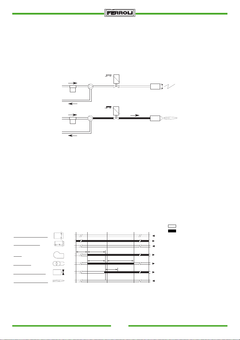
SETTING AT WORK
1) Preliminary operations
- mount the pressure gauge and vacuometer on the pump (remove after start-up)
- open the gate valves along the heating oil pipe
- power the equipment by means of the main switch
- close the thermostat line (boiler/room)
- release the appliance (by depressing the red button).
2) Start-up
VE
GP
VE
GP
a) Once the thermostatic line has been closed, the burner motor will start operating together with the pump
the intaken heating oil will be totally conveyed towards the return side. The burner fan and ignition
transformer will also be operating and the appliance will proceed with the following phases:
- flue pre-ventilation
- pre-flushing of part of the heating oil circuit
- pre-ignition, with discharge between the tips of the electrodes.
b) At the end of the pre-flushing phase, the electromagnetic valve will open and the heating oil will reach
the injector from which it will be finely atomized.
Contact with the spark between the electrode tips will form the flame. The safety time will now start.
WORK CYCLE
Signals required on input
Signals on output
TA-TC Room thermostat
FR Photoelectric resistance
MB Burner motor
TR Ignition transformer
VE Electromagnetic valve
Tm Heater Pr minimum
thermostat
A Start-up without preheater
B Flame on
C Normal operation
D Adjustment stop (TA-TC)
A' Start-up with preheater
t1 Pre-ventilation time: 13 sec.
t2 Safety time: 10 sec.
t3 Pre-ignition time: 13 sec.
t3n After-ignition time: 15 sec.
tw Preheating time: 60/90 sec.
Room-boiler thermostat
Preheater with TM
Motor
Transformer
Electromagnetic valve
Photoelectric resistance
10
A' A B C D
TA - TC
Pr
Tm
tw t1
MB
TR
VE
FR
t3 t3 n
t2
Fig. 10
SUN
1
8
3
3
7
4
11
12
Page 11
S.p.A.
MAINTENANCE
The burner requires routine maintenance that must be carried out by qualified personnel.
Maintenance becomes essential for correct burner operation, thus preventing excessive fuel consumptions
and reducing the polluting effect.
Before cleaning or inspecting the burner in any way, always switch off the electricity supply by means of
the main switch.
Most of the parts can be inspected by removing the casing.
The basic operations are the following:
- Check that there are no clogged or dented fuel supply or return pipes.
- Clean the filter on the fuel intake line.
- Check that fuel consumption is correct.
- Clean the combustion head around the fuel outlet area, on the swirl disk.
- All the burner to run at top rate for about ten minutes, then examine combustion by checking:
• That all the parts described in this handbook are correctly calibrated
• The temperatures of the stack fumes
• The percentage of CO
in the fumes
2
• The percentage of CO (ppm)
• The opacity index of the fumes, according to Bacharach’s scale.
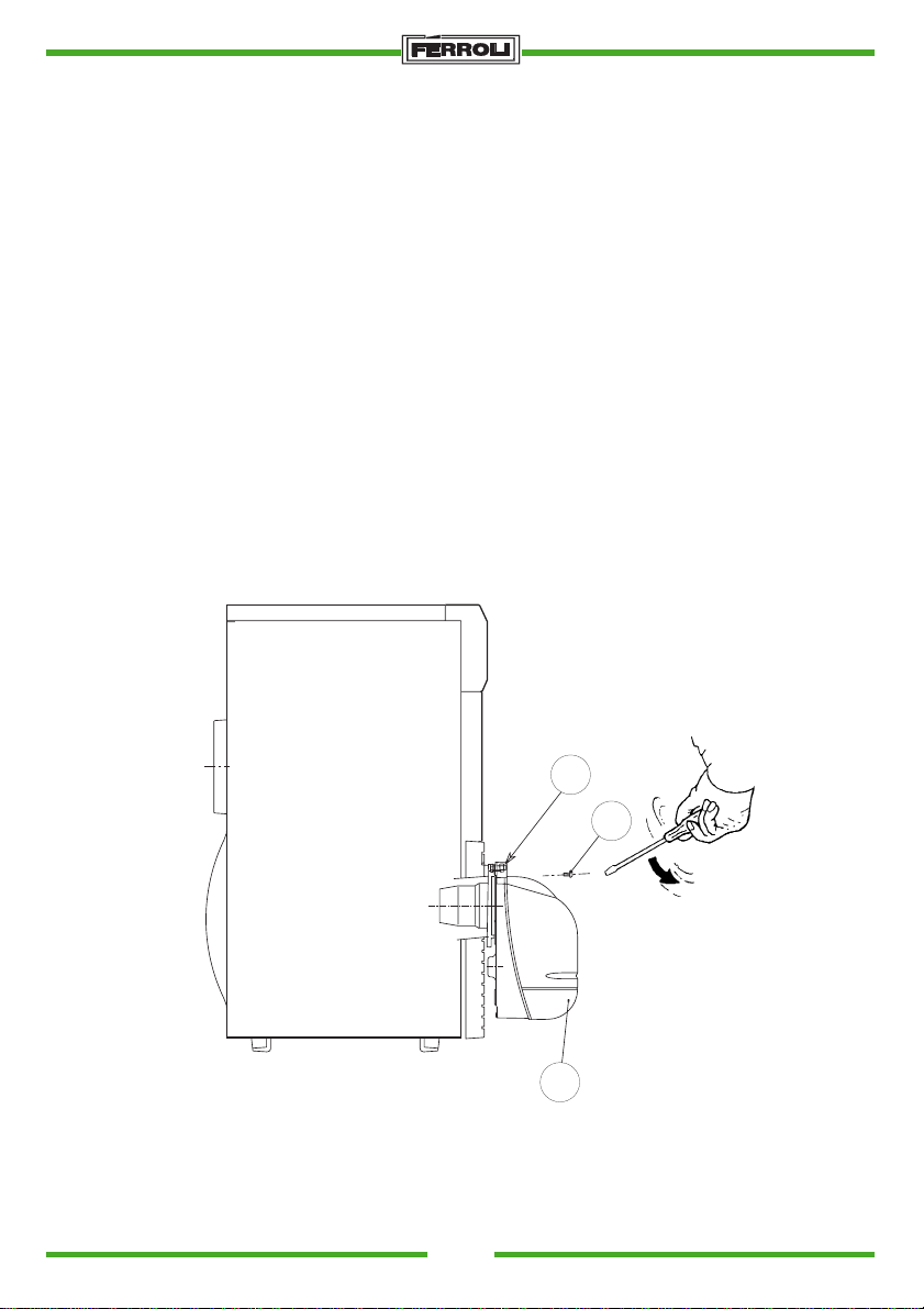
DEMOUNTING AND SERVICING THE BURNER (Fig. 11)
C
A
B
Fig. 11
- Remove the casing (B) by slackening screw (A) for access to all the parts.
- Slacken nut (C) and position the burner in order to reach the injector fixed in screw.
SUN
11
Page 12

S.p.A.
TROUBLESHOOTING
FAULTS PROBABLE CAUSES REMEDIES
The motor fails to operate No electricity a) Check the fuses
b) Check the thermostats
(room, boiler, safety)
The motor operates but the
flame fails to ignite, thus
blocking the appliance
The burner starts, the flame
ignites but the appliance
blocks
The flame is irregular and
short, with sparks
a) No discharge from from
the electrodes
b) Clogged injector
c) No fuel supplied
a) Dirty photoelectric resi-
stance
b) Badly atomizing injector
a) Badly atomizing injector
b) Pump pressure toon low
c) Water in the heating fuel
a) check that the plugs are
in the correct position and
clean them
b) Clean or replace the
injector
c) Check the level of the
heating fuel in the cistern.
Check that no gate valves are closed along the
heating oil line. Check
that the line and pump
filters are clean
a) Clean the photoelectric
resistance
b) Clean or replace the
injector
a) Clean or replace the
injector
b) Chek and raise the pres-
sure
c) Remove water from the
cistern and clean the filters
Smoky flame a) Badly atomizing injector
b) Insuf ficent combustion air
SUN
12
a) Clean or replace the
injector
b) Check that the air lock
opens regularly. Check
that the fan is not dirty
Page 13
27
26
32 31
8
30
2
1 5
13
16
15
10
2325 34
12
23
24
9
7
17
14 11 6
2822
29
21 20
35
19
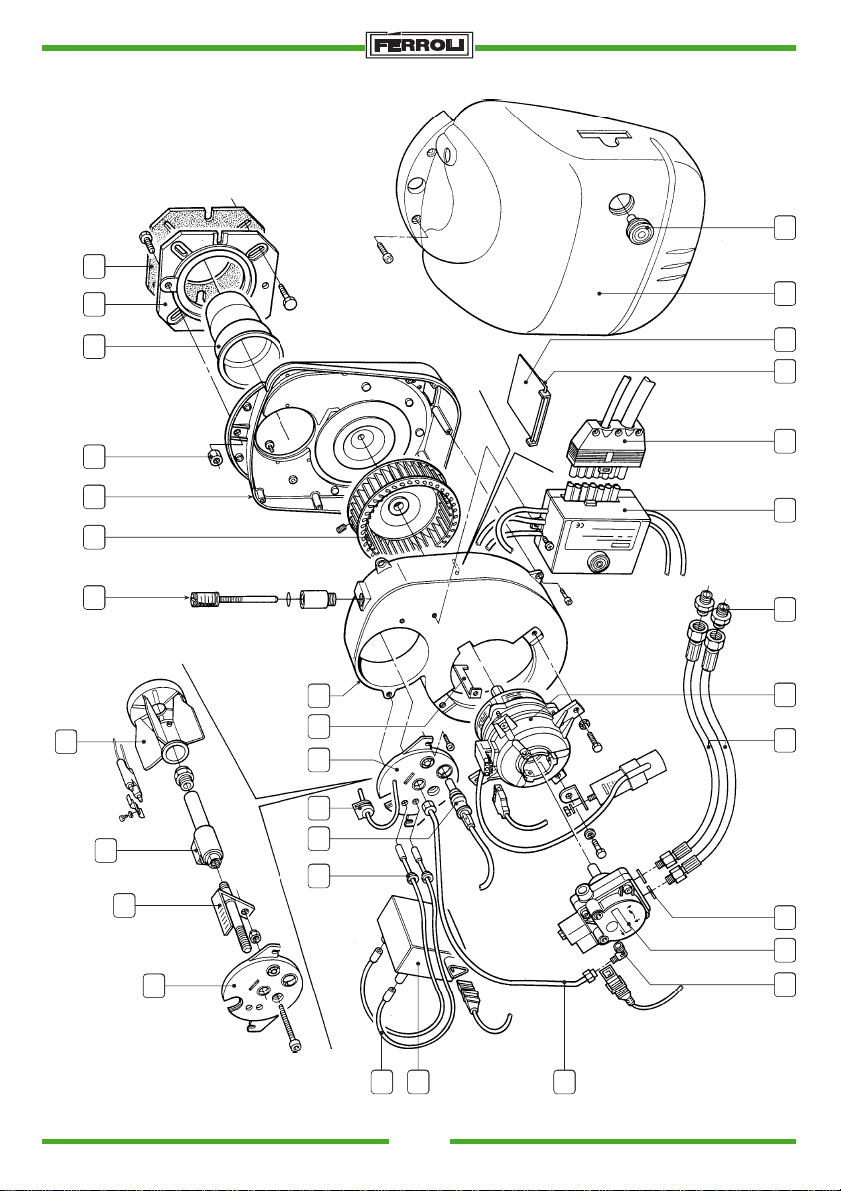
COMPONENTS
S.p.A.
Fig. 12
SUN
13
Page 14

S.p.A.
LIST COMPONENTS
Pos. Code Description
1 3340089/0 Elbow, 1/8 M, 4 diam. coupling
2 3370093/0 Washer, int. diam. 13.5, ext. diam. 18 x 2
3
4
5 3560092/0 Pump, model AS47A 1564 IP 0500
6 3560100/0 Nut, M8
7 3560217/0 Deflector, art. 94040 Meku
8 3560156/0 Nipple, 3/8” - 1/4”
9a 3560086/0 Preheater (for G6R only)
9b 3560207/0 Nozzle holder (for G6 version)
10 3560162/1 Cable, length 330 with resistance
11 3560167/0 Burner shield
12 3560168/0 Burner screw stoker
13 3560169/0 Motor, clockwise rotation, 70W
14 3560170/0 Burner fan, 146 x 49 F. 12.7 LHR
15 3560171/0 Transformer, Brahma art. TP2STPAF 55 VA
16 3560172/0 Oil feed pipe
17 3890000/0 Air regulation shaft
18
19 3560176/0 Air deflector
20 3560177/0 Air regulation
21 3560178/0 Air damper pin
22 3560179/0 Draught tube art. 98008 Meku
23 3560180/0 Stoker screw cover
24 3560181/0 Spray nozzle shaft
25 3560182/0 Grommet for electrodes
26 3560183/0 Burner casing
27 3560184/0 Reset button
28 3560185/0 Flange
29 3560186/0 Flange gasket
30 3560204/0 Flexible hose ST6 1/4” FC - 1/4” MG, length 900
31 3650360/0 Connector M. 7P art. S7P - M - STD - T14
32 3890112/0 Control unit assembly
33
34 3560173/0 Photoelectric cell
35 3560208/0 Preheater bridge burner Sun G6
14
SUN
Page 15

S.p.A.
INDICE pag.
Généralités - Caractéristiques techniques ............................................................................................ 4
Principaux composants - Plage de travail du brûleur.......................................................................... 17
Raccordements électriques................................................................................................................. 18
Circuit d'alimentation du fuel ............................................................................................................... 19
Montage sur la chaudière - Réglage pression pompe ........................................................................ 20
Choix du gicleur .................................................................................................................................. 21
Réglage de la tête - Exemple de réglage de la combustion
Position électrodes-déflecteur............................................................................................................. 22
Mise en service - Cycle de l'appareillage............................................................................................ 23
Entretien.............................................................................................................................................. 24
Recherche des pannes ....................................................................................................................... 25
Nomenclature pièces ..................................................................................................................... 26-27
SUN
15
Page 16
S.p.A.
GÉNÉRALITÉS
Ferroli a le plaisir de vous présenter sa série de brûleurs à fuel pour chaudières domestiques à débits
thermiques compris entre 13,3 et 58,1 kW. L’aspect et la forme compacte font que ces appareils peuvent
s’adapter aux principales chaudières commercialisées aujourd’hui.
En utilisant des technologies modernes Ferroli a produit ces nouveaux appareils capables d’optimiser le
mélange air-combustible, au profit de rendements élevés, de faibles concentrations de CO et de NOx,
et d’une flamme très silencieuse.
Voici leurs principales caractéristiques techniques:
- Réglage fin de la position de la tête de combustion par rapport à la buse au moyen d’une vis
micrométrique
- Réglage précis de l’air à l’aspiration
- Clapet d’air à fermeture par gravité lors de l’arrêt du brûleur permettant de limiter considérablement les
déperditions de chaleur de la chaudière pendant les pauses.
- Le brûleur intègre un préchauffage sur le circuit du gicleur pour améliorer la combustion et assurer un
démarrage immédiat après des arrêts prolongés durant les périodes les plus froides et avec du fuel
paraffiné.
- Sur tous les appareils les opérations d’inspection et de maintenance sont facilitées.
CARACTERISTIQUES TECHNIQUES ET ENCOMBREMENTS
96
0
180
16
286
Fig. 1
250
Ø90
227
Type
Debit combustible kg/h
Puissance Thermique kW
Ventilateur
Prechauffage
Tete pulverizateur
Transformateur d’allumage
Moteur
Combustible
Øe Øi
SUN
min.
max.
min.
max.
Ø 170
SUN
G.6 R G.6
1,12
4,90
13,3
58,1
146-48 rsx 40 pale
110 W
64-16 nr. 6 tagli
2x7 kV 40 mA
70W 0.6A 2735 g/min
Fuel max 20 °C 1.5 E
220 - 240V 50HzAlimentation electrique
220 WPuissance absorbée
1,8
4,90
21,3
58,1
/
170 W
IP40Clacs de protection
Ø 140
Ø91
Page 17
S.p.A.
PRINCIPAUX COMPOSANTS
16
8
3
V
4
Légende
1 Pompe à fuel
2 Moteur
3 Vanne électromagnétique
4 Corps du brûleur
5 Bouton-poussoir rearmement
6 Coffret de contrôle
7 Cellule
8 Transformateur d’allumage
9 Plaque de support brûleur
PLAGE DE TRAVAIL DU
BRULEUR
∆p mbar
0.6
0.5
0.4
0.3
0.2
0.1
kg/h
13
0
5
10
15
20
12 11 10 9
18
7
6
P
1
14
5
2
17
15
Fig. 2
10 Ligne gicleur
11 Electrodes d’allumage
12 Buse
13 Vis de régl. clapet d’air
14 Clapet automatique
15 Ventilateur
16 Réglage tête de combustion
17 Réglage pression pompe
18 Prise de pression
SUN G.6 R
0
1
1.5
2.0 5.04.54.03.53.02.5
0.6
0.5
0.4
0.3
∆p mbar
0.2
0.1
Fig. 3
kg/h
0
1
1.5
Pression dans la chambre de combustion ∆p mbars
Débit de mazout en kg/h
2.0 5.04.54.03.53.02.5
SUN
SUN G.6
17
Page 18
RACCORDEMENTS ELECTRIQUES
NNNPh
IG
F
TS
L1 N T1 T2 S3 B4
L1
N
LS
TA - TC
T2
T1
w
S3 B4
CO
h
PB SC
S.p.A.
CONNECTEUR PRÉCHAUFFAGE
Raccordement pour vers.
sans préchauffage
GN
M
B
N
4321
Légende
CO Compteur horaire
F Fusible
FR Photorésistance
IG Interrupteur général
LS Lampe sécurité
MB Moteur du brûleur
PB Prise brûleur
PR Préchauffage (seulement pour ver. G6R)
SC Fiche
TA-TC Thermostat chaudière - ambiance
TR Transformateur d’allumage
TS Thermostat de sécurité
TM Thermostat de minimum
VE Vanne électromagnétique
Câble préchauffage
M
1~
MB
VE
TR
Tm
PR
FR
12 34567891011122
Fig. 4
Les raccordements électriques que doit réaliser l’installateur sont:
- circuit d’alimentation
- circuit des thermostats
- voyant de blocage et compteur horaire éventuels
Attention
- ne pas inverser le neutre avec la phase
- réaliser un bonne mise à la terre
18
SUN
Page 19
S.p.A.
CIRCUIT D’ALIMENTATION DU FUEL
Attention: Avant de faire démarrer le brûleur assurez-vous que le tuyau de refoulement du combustible
n’est pas bouché. Une contre-pression excessive provoquerait la rupture de l’organe
d’étanchéité de la pompe.
Il est nécessaire d’installer un filtre sur le circuit d’alimentation du combustible.
A
Fig. 5a
B
Fig. 5b
C
Fig. 5c
D
(m)
0.5
1.0
1.5
2.0
(m)
0.0
0.5
1.0
1.5
2.0
2.5
3.0
3.5
(m)
0.0
0.5
1.0
1.5
2.0
2.5
3.0
3.5
H
H
H
L (m)
Øi 8 mm. Øi 10 mm.
10
20
40
60
Øi 8 mm. Øi 10 mm.
25 60
21
18
15
12
10
8
6
Øi 8 mm. Øi 10 mm.
25 60
21
18
15
12
10
8
6
20
40
80
100
L (m)
50
44
38
32
26
20
16
L (m)
50
44
38
32
26
20
16
CIRCUITS HYDRALIQUES
A Alimentation par gravité
B Alimentation par aspiration
C Alimentation à siphon
D Alimentation à boucle
Fig. 5d
SUN
Nota: pour chaque coude ou vanne, il faut additionner
0,25 mètres à la longueur de la tuyauterie
(perte de charge).
L Longueur totale du tuyau d’aspiration, parcours
verticaux inclus.
H Différence de niveau
Øi Diamètre intérieur de la tuyauterie
19
Page 20
S.p.A.
MONTAGE SUR LA CHAUDIERE
6030
90
0
2
1
4
5
3
4
5
Fig. 6
- Placer la vis 2 (M8x25) dans la plaque 3
- Placer la plaque 3 sur la chaudière et fixer par les vis 5 (N. 4 M8x30) en interposant une garniture isolante 1.
- Placer le brûleur sur la plaque de la chaudière et fixer à la vis 2 par l’écrou 4
REGLAGE PRESSION POMPE
3
6
Type BFP
NO.
DENMARK
1
MADE IN
2
V
P
3
54
5
V
230v. 50Hz.
VA. 11
1
DELTA
Cod. M81
DANFOSS BFP 11 R3
1
2
3
PV
4
20
2
4
DELTA VM1 RL2
6
P
Legenda
1 - Aspiration
2 - Retour
3 - Sortié gicleur
4 - Prise pression
5 - Prise pression
6 - Vis reglage pression
Fig. 7
SUN
5
6
m h2O
SUNTEC AS
Page 21
S.p.A.
CHOIX DU GICLEUR
Le choix doit être fait en fonction de la puissance du foyer de la chaudière sans oublier que le fuel a un
pouvoir calorifique (P.C.I.) de 10.200 kcal/kg. Le tableau indique le débit ou la consommation de fuel en
kg/h et en kW, en fonction de la grandeur du gicleur (en GPH) et de la pression de la pompe (en bars).
Dans le cas de brûleurs à préchauffage, la valeur effective de débit est inférieure de 10% environ par
rapport aux valeurs indiquées dans le tableau.
Tableau débit des gicleurs pour mazout
N.B. Il est important de tenir compte du fait que le débit des injecteurs fuel peut varier de ±5%.
Gicleur
G.P.H.
0,40
0,50
0,60
0,65
0,75
0,85
1,00
1,10
1,20
1,25
1,35
1,50
1,65
1,75
2,00
2,25
2,50
3,00
6
1,18
1,47
1,77
1,91
2,2
2,5
2,94
3,24
3,53
3,68
3,97
4,42
4,86
5,15
5,89
6,62
7,36
8,83
7
1,27
1,59
1,91
2,07
2,38
2,70
3,18
3,50
3,82
3,97
4,29
4,77
5,25
5,56
6,30
7,15
7,95
9,54
Pression pompe kg/cm
89
1,36
1,44
1,70
1,80
2,04
2,16
2,21
2,34
2,55
2,70
2,89
3,06
3,40
3,61
3,74
3,97
4,08
4,33
4,25
4,50
4,59
4,87
5,10
5,41
5,61
5,95
5,95
6,31
6,80
7,21
7,65
8,15
8,50
9,01
10,20
10,82
10
1,52
1 ,90
2,28
2,47
2,85
3,23
3,80
4,18
4,56
4,75
5,13
5,70
6,27
6,65
7,60
8,55
9,50
11,40
11
1,59
1,99
2,39
2,59
2,99
3,39
3,99
4,38
4,78
5,00
5,38
5,90
6,58
6,98
7,97
8,97
9,97
11,96
Débit en sortie du gicleur (en kg/h)
12
1,67
2,08
2,50
2,71
3,12
3,54
4,16
4,58
5,00
5,20
5,62
6,24
6,87
7,29
8,33
9,37
10,41
12,49
2
13
1,73
2,17
2,60
2,82
3,25
3,68
4,33
4,77
5,20
5,40
5,85
6,50
7,15
7,58
8,67
9,75
10,83
13,00
14
1,80
2,25
2,70
2,92
3,37
3,82
4,50
4,95
5,40
5,60
6,07
6,75
7,42
7,87
8,99
10,12
11,24
13,49
15 17
16
1,86
1,92
2,33
2,40
2,79
2,88
3,03
3,12
3,49
3,61
3,96
4,09
4,65
4,81
5,12
5,29
5,59
5,77
5,80
6,00
6,28
6,49
6,98
7,21
7,68
7,93
8,15
8,41
9,31
9,61
10,47
10,85
11,64
12,02
13,96
14,42
1,98
2,48
2,97
3,22
3,72
4,21
4,96
5,45
5,95
6,20
6,69
7,43
8,18
8,67
9,91
11,15
12,39
14,87
SUN
21
Page 22
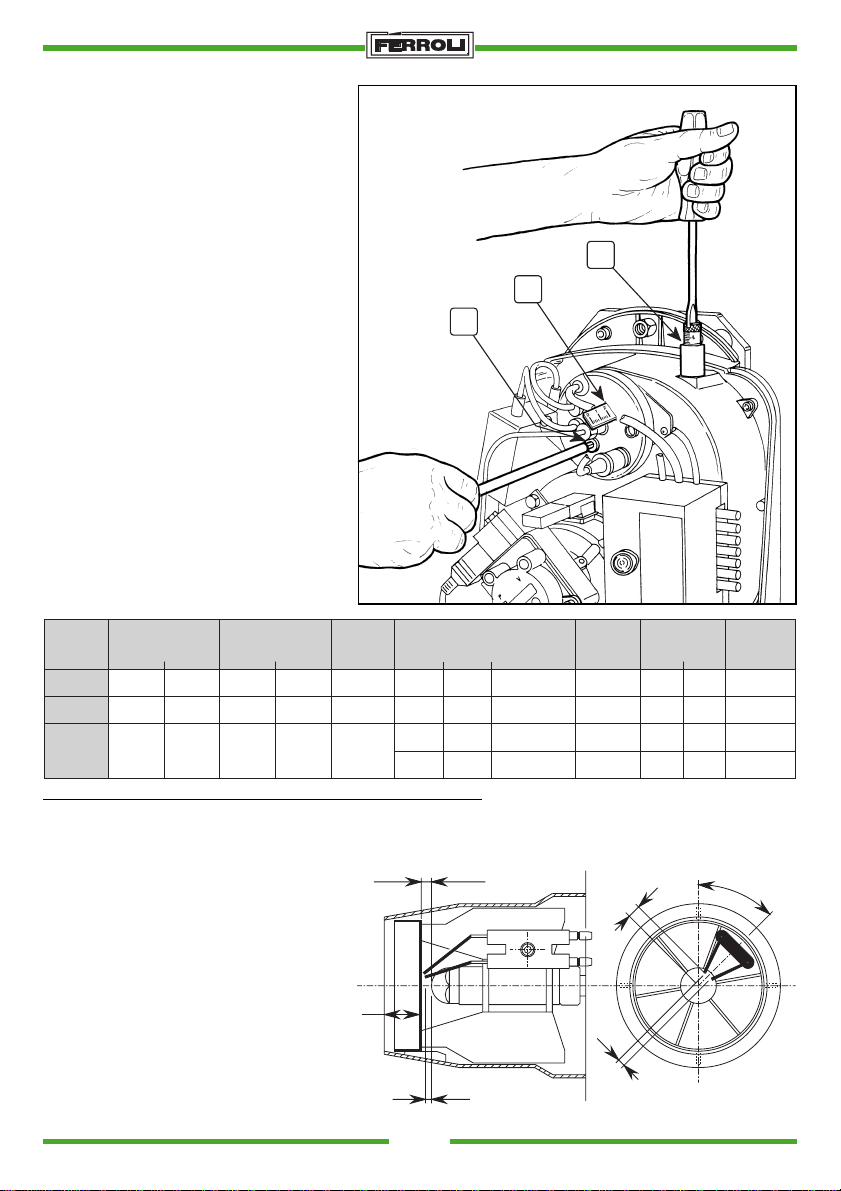
13. RÉGLAGE DE LA TETE ET DE L'AIR
C
A
B
(ill. 8)
Le réglage de la tête dépend de la puissance du brûleur.
Il doit être règle en agissant sur la vis "B" en
s'assurant que le repère sur la réglette soit
conforme au tableau de prescription
ci-dessous.
Si on modifie le réglage de la tête, il est
nécessaire de modifier le réglage de l'air.
Pour le réglage de l'air, agir sur la vis "C" en
s'assurant que le repère sur la vis est conforme au tableau de prescription ci-dessous.
A l'arrête du brûleur, le clapet d'air se
ferme automatiquement.
Exemple de réglage de la combustion
Le gicleur, la pression de la pompe, le
réglage de la tête de combustion, le réglage du débit d’air sont définis en fonction
du débit demandé, à partir du tableau
suivant. Vérifiez la combustion.
S.p.A.
Fig. 8
Type
Chaudiere
GN1.02
GN1.03
GN1.04
Puissance
thermique
kW
23,3
34,9
46,5
kcal/h
20.000
30.000
40.000
thermique
kW
25,8
38,7
51,6
Debit
22.200
33.200
44.400
kcal/h
Debit
Bruleur
Kg/h
2,176
3,25
4,35
* Réglage pour la version du brûleur sans préchauffeur
POSITION ELECTRODES - DÉFLECTEUR (Fig. 9)
Après avoir monté le gicleur, vérifier que
les électrodes et le déflecteur sont
positionnés conformément aux cotes
indiquées ci-dessous.
Vérifier les cotes après chaque
intervention sur la tête.
L
Fig. 9
22
1
Gicleur
US
Angle
Gall/h
0,6
60°
0,85
60°
1,1
60°
1,0
60°
*** * ** *
3
Code
3560154/0
3560134/0
3560128/0
3560127/0
Pression
pompe
Bar
12
12
12
12
Réglage
Repère
6
10
15
18
tête
L
18
22
27
31
Réglage
45.0°
d’air
Repère
5
10
15
15
6.5
3.5
SUN
Page 23
S.p.A.
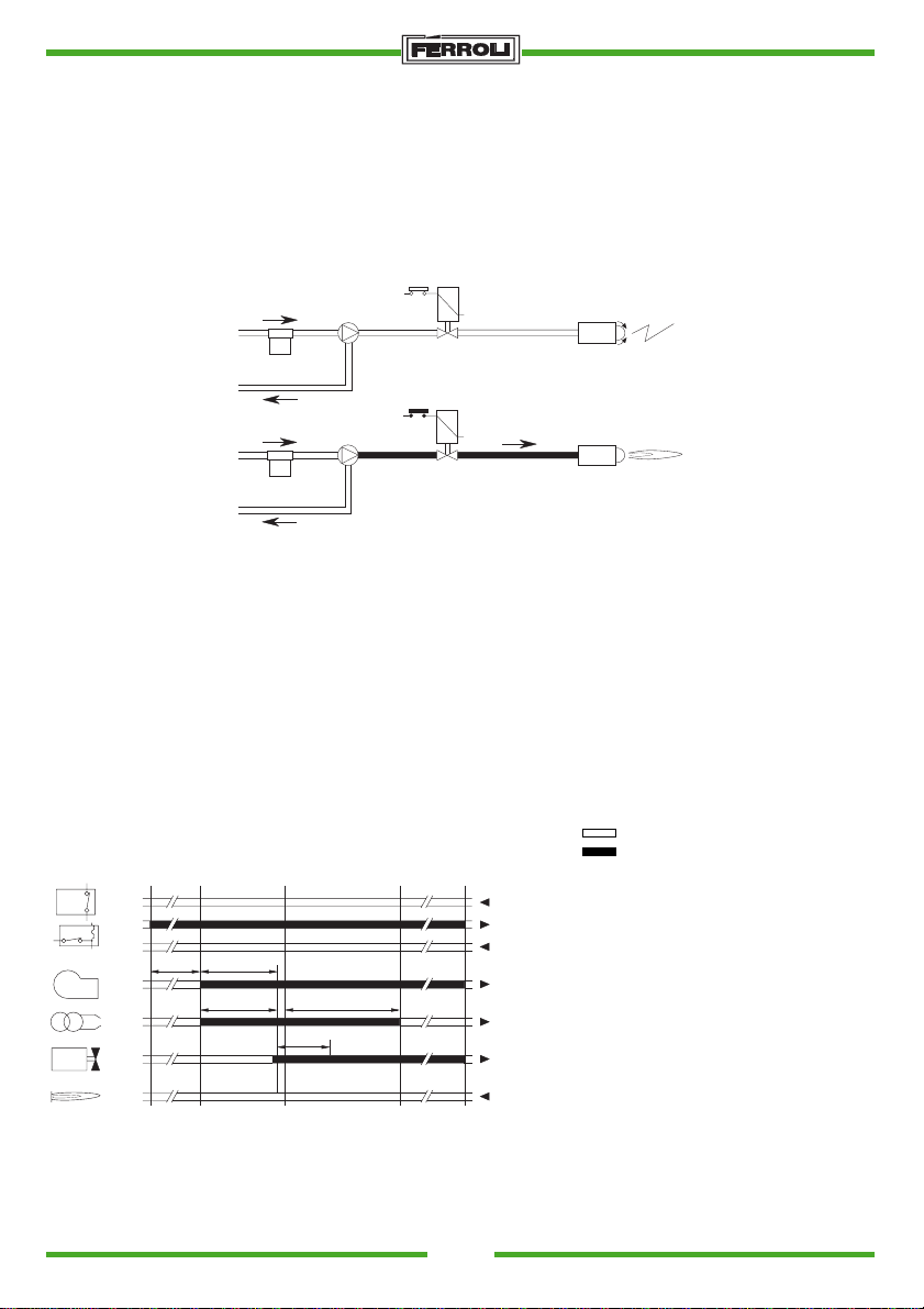
MISE EN SERVICE
1) Opérations préliminaires
-montez le manomètre et vacuomètre sur la pompe (les enlever après mise en service)
-ouvrez les clapets le long de la tuyauterie du fuel
-mettez la machine sous tension au moyen de l’interrupteur général.
-fermez le circuit des thermostats (chaudière/ambiance)
-débloquez l’appareil (en poussant le bouton rouge)
2) Démarrage
VE
GP
VE
GP
a)Lors de la fermeture du circuit thermostatique le moteur du brûleur se met à tourner avec la pompe:
le fuel aspiré est entièrement refoulé. Le ventilateur du brûleur et le transformateur d’allumage se
mettent en marche, réalisant les phases de:
- préventilation du foyer
- prélavage d’une partie du circuit du fuel
- préallumage, avec décharge entre les pointes des électrodes.
b)A la fin du prélavage l’appareillage ouvre la vanne électromagnétique: le mazout atteint le gicleur, d’où
il sort pulvérisé.
Le contact avec la décharge entre les pointes des électrodes, produit la flamme et simultanément le
temps de sécurité démarre.
CYCLE COFFRET
A' A B C D
TA - TC
Pr
Tm
tw t1
MB
TR
VE
FR
t3 t3 n
t2
Fig. 10
SUN
1
8
3
3
7
4
11
12
Signaux nécessaires en entrée
Signaux de sortie de l’appareil
TA-TC Thermostat ambiant
FR Photorésistance
MB Moteur brûleur
TR Transformateur d’allumage
VE Vanne électromagnétique
Tm Thermostat de minimum
préchauffage Pr
A Début démarrage sans
préchauffage
B Présence flamme
C Fonctionnement normal
D Arrêt de réglage (TA - TC)
A' Début démarrage avec
préchauffage
t1 Temps de préventilation: 13 sec.
t2 Temps de sécurité: 10 sec.
t3 Temps de pré-allumage: 13 sec.
t3n Temps de post-allumage: 15 sec.
tw Temps de préchauffage: 60/90 sec.
23
Page 24
S.p.A.
ENTRETIEN
Le brûleur requiert un entretien périodique, qui doit effectué par un technicien spécialisé.
L’entretien devient essentiel pour un bon fonctionnement du brûleur, évitant des consommations
excessives de combustible et réduisant la pollution de l’environnement.
Avant d’effectuer une opération quelconque d’entretien ou un contrôle, couper l’alimentation électrique
au brûleur au moyen de l’interrupteur général de l’installation.
La plupart des composants peut être inspectée en enlevant le capot.
PRINCIPALES OPERATIONS D’ENTRETIEN:
- Vérifier que les tuyaux d’alimentation et de refoulement du combustible ne sont pas obstrués ou
endommagés.
- Effectuer le nettoyage du filtre de la ligne d'aspiration du combustible.
- Relever la consommation correcte de combustible.
- Nettoyer de la tête de combustible dans la zone de sortie du combustible, sur le deflecteur.
- Laisser fonctionner le brûleur à plein régime pendant environ dix minutes, puis effectuer une analyse
de la combustion en vérifiant:
• le bon réglage de tous les éléments indiqués dans cette notice
• Les températures des fumées dans le conduit
• Le pourcentage de CO
• La teneur en CO (ppm)
2
• L’indice d’opacité des fumées, suivant l’échelle de Bacharach.
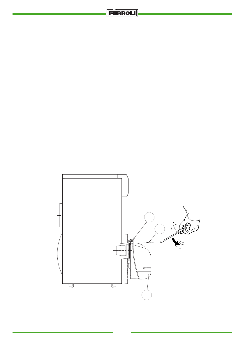
OPERATIONS DE DEMONTAGE ET ENTRETIEN DU BRULEUR
C
A
Fig. 11
B
- Pour avoir accès à tous les accessoires démontez le capot (B) en dévissant la vis (A).
- Dévissez l’écrou (C) et tournez le brûleur de manière à avoir accès au gicleur monté dans la vis.
24
SUN
Page 25

RECHERCHE DES PANNES
ANOMALIE CAUSES PROBABLES REMEDES
S.p.A.
Le moteur ne tourne pas. Absence d’energie electri-
que.
Le moteur tourne mais la
flamme ne se forme pas,
a) Pas de décharge aux
électrodes.
avec arrêt et mise en securité.
b) Gicleur bouché.
c) Le combustible n’arrive
pas.
Le brûleur ne démarre pas.
La flamme s’allume, puis le
a) Photorésistance encras-
see.
brûleur s’arrête en securité.
b) Le gicleur pulvérise mal.
Flamme irrégulierè, courte
a) Le gicleur pulvérise mal.
avec étincelles.
b) La pression dans la pom-
pe est trop faible.
a) Contrôlez les fusibles.
b) Contrôlez les thermostats
(ambiance, chaudiere,
securite).
a) Vérifiez que la position
des electrodes est correcte; nettoyezles.
b) Nettoyez ou remplacez
le gicleur.
c) Vérifiez le niveau de fuel
dans la citerne; vérifiez
qu’il n’y a pas de clapets
fermes sur le circuit du
mazout; vérifiez la propete du filtre du circuit et da
la pompe, er attention
etancheite circuit fuel.
a) Nettoyez la photoresi-
stance.
b) nettoyez ou remplacez le
gicleur.
a) ou remplacez le gicleur
b) Vérifiez et augmentez la
pression.
c) Il y a de l’eau dans le fuel.
La flamme est fumeuse. a) Gicleur qui pulverise mal.
b) Peu d’air de combustion.
SUN
c) Faites enelever l’eau
dans le citerne et nettoyez les filtres.
a) Nettoyez ou remplaceze
le gicleur.
b) Vérifiez que le clapet at-
mospherique s’ouvre regulierement; Contrôlez la
propete du ventilateur.
25
Page 26
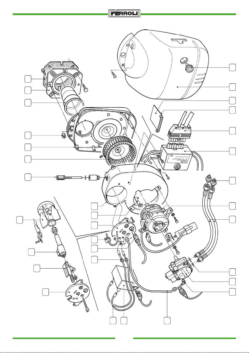
2726
32
31
8
30
21 5
13
16
15
10
23
25 34
12
23
24
9
7
17 14
11 6
2822 29
21 20
35 19
BRÛLEUR COMPOSANTS
S.p.A.
Fig. 12
SUN
26
Page 27
S.p.A.
Pos. Code Description
1 3340089/0 Coude 1/8M - Raccord Ø4
2 3370093/0 Rondelle Øi 13,5 - Øe 18x2
3
4
5 3560092/0 Pompe AS47A 1564 IP 0500
6 3560100/0 Ecrou M8
7 3560217/0 Déflecteur art. 94040 Meku
8 3560156/0 Nipple 3/8" - 1/4"
9a 3560086/0 Prechaufeur G6R
9b 3560207/0 Porte gicleur
10 3560162/1 Câble lg. 330
11 3560167/0 Bouclier brûleur
12 3560168/0 Carter helicoidale brûleur
13 3560169/0 Moteur 70W
14 3560170/0 Turbine brûleur 146x49 F. 12,7 RSX
15 3560171/0 Transformateur Brahma art. TP2STPAF 55VA
16 3560172/0 Tube alimentation mazout
17 3890000/0 Arbre regulation air
18
19 3560176/0 Deflecteur air
20 3560177/0 Serrage air
21 3560178/0 Pivot serrage air
22 3560179/0 Buse art. 98008 Meku
23 3560180/0 Couvercle carter helicoidale
24 3560181/0 Ligne gicleur
25 3560182/0 Passe-câble
26 3560183/0 Capot du brûleur
27 3560184/0 Bouton pour réarmement
28 3560185/0 Bride
29 3560186/0 Joint d’étancheité
30 3560204/0 Flexible ST6 1/4" FC - 1/4" MG lg. 900
31 3650360/0 Connecteur M. 7P art. S7P - M - STD - T14
32 3890112/0 Coffret
33
34 3560173/0 Cellule photo-électrique
35 3560208/0 Pont prechaufer pour brûleur Sun G6
SUN
27
Page 28

37047 SAN BONIFACIO - VR - ITALY
tel. 045/6139411 - tlx 480172
fax 045/6100233-6100933
cod. 3543308/1 - 04/00
 Loading...