

Page 1
&
cod. 3541C702 — Rev. 01 - 06/2014
SKY C B
40
50 50==
27
789
595
a4
A
B
195
95
11 CB
14 CB
A
295
335
Modello
798
a4
Ø
110
130
B
210
250
IT -
ISTRUZIONE PER L’USO L'INSTALLAZIONE E LA MANUTENZIONE
EN -
INSTRUCTIONS FOR USE, INSTALLATION AND MAINTENANCE
FR -
INSTRUCTIONS D'UTILISATION, D'INSTALLATION ET D'ENTRETIEN
TR -
KULLANMA, KURULUM VE BAKøM TALIMATLAR
ø
Page 2

SKY C B
2
IT
cod. 3541C702 - Rev. 01 - 06/2014
IT
1. AVVERTENZE GENERALI
• Leggere ed osservare attentamente le avvertenze contenute in questo libretto di istruzioni.
• Dopo l’installazione dell’apparecchio, informare l’utilizzatore sul funzionamento e consegnargli il presente manuale che costituisce parte integrante ed essenziale del prodotto e
deve essere conservato con cura per ogni ulteriore consultazione.
• L’installazione e la manutenzione devono essere effettuate in ottemperanza alle norme vigenti, secondo le istruzioni del costruttore e devono essere eseguite da personale professionalmente qualificato. È vietato ogni intervento su organi di regolazione sigillati.
• Un’errata installazione o una cattiva manutenzione possono causare danni a persone, animali o cose. È esclusa qualsiasi responsabilità del costruttore per i danni causati da errori
nell’installazione e nell’uso e comunque per inosservanza delle istruzioni.
• Prima di effettuare qualsiasi operazione di pulizia o di manutenzione, chiudere il gas attraverso gli appositi organi di intercettazione.
• In caso di guasto e/o cattivo funzionamento dell’apparecchio, disattivarlo, astenendosi da
qualsiasi tentativo di riparazione o di intervento diretto. Rivolgersi esclusivamente a personale professionalmente qualificato. L’eventuale riparazione-sostituzione dei prodotti dovrà essere effettuata solamente da personale professionalmente qualificato utilizzando
esclusivamente ricambi originali. Il mancato rispetto di quanto sopra può compromettere
la sicurezza dell’apparecchio.
• Questo apparecchio dovrà essere destinato solo all’uso per il quale è stato espressamente
previsto. Ogni altro uso è da considerarsi improprio e quindi pericoloso.
• Gli elementi dell’imballaggio non devono essere lasciati alla portata di bambini in quanto
potenziali fonti di pericolo.
• L’apparecchio non è destinato ad essere usato da persone (bambini compresi) le cui capacità fisiche, sensoriali o mentali siano ridotte, oppure con mancanza di esperienza o di
conoscenza, a meno che esse abbiano potuto beneficiare, attraverso l’intermediazione di
una persona responsabile della loro sicurezza, di una sorveglianza o di istruzioni riguardanti l’uso dell’apparecchio.
• Lo smaltimento dell'apparecchio e dei suoi accessori deve essere effettuato in modo adeguato, in conformità alle norme vigenti.
• Le immagini riportate nel presente manuale sono una rappresentazione semplificata del
prodotto. In questa rappresentazione possono esserci lievi e non significative differenze
con il prodotto fornito.
2. ISTRUZIONI D’USO
2.1 Presentazione
SKY C B è uno scaldabagno istantaneo per la produzione di acqua calda sanitaria ad
alto rendimento funzionante a gas naturale oppure a gas propano, dotato di bruciatore
atmosferico ad accensione elettronica, alimentato a batteria, destinato all’installazione
in interno.
2.2 Pannello comandi
Pannello
fig. 1 - Pannello di controllo
Legenda pannello fig. 1
1 Visualizzazione temperatura acqua calda sanitaria
2 Segnalazione livello batterie
3 Regolazione potenza del bruciatore/off
4 Regolazione della temperatura
5 Simbolo fiamma
Indicazione durante il funzionamento
Tabella. 1 - Simbologia display
Durante la richiesta sanitario (generata dal prelievo d’acqua calda sanitaria), il display
visualizza l’attuale temperatura d’uscita dell’acqua calda sanitaria.
2.3 Accensione e spegnimento
Verifiche e operazioni preliminari
1. Accertarsi che i rubinetti dell'acqua calda siano chiusi.
2. Aprire il rubinetto di alimentazione del gas allo scaldabagno, situato sull'allacciamento del gas all'apparecchio.
3. Verificare che le batterie da 1,5 V siano inserite nella rispettiva sede, con la polarità
corretta (+ e -).
Per la loro sostituzione vedere “Sostituzione batterie” a pag. 5..
4. Verificare anche che le batterie abbiano una carica sufficiente per il funzionamento
dello scaldabagno.
Accensione
Ruotare la manopola in posizione del livello di riscaldamento dell'acqua richiesto.
fig. 2 - Accensione
L’apparecchio sarà immediatamente pronto per funzionare ogni qualvolta si prelevi acqua calda sanitaria.
Spegnimento
Il bruciatore si spegne automaticamente quando cessa la richiesta di acqua calda sanitaria.
Non è necessaria alcuna manovra particolare per effettuare una nuova fase di accensione.
Per lo spegnimento completo dell’apparecchio portare la manopola in posizione .
fig. 3 - Apparecchio disattivato
In caso di spegnimento prolungato chiudere il rubinetto gas a monte dell’apparecchio.
B
Per lunghe soste durante il periodo invernale, al fine di evitare danni dovuti al
gelo, è consigliabile scaricare tutta l’acqua dallo scaldabagno.
2.4 Regolazioni
Impostazione manuale della potenza del bruciatore
Con la manopola di regolazione della potenza (rif. 3 - fig. 1) è possibile selezionare la
potenza dello scaldabagno, minima o massima e posizioni intermedie a seconda del livello di riscaldamento dell'acqua richiesto. Girando la manopola in senso antiorario, l'apparecchio riscalda l'acqua alla massima potenza. Se la temperatura fosse troppo
elevata, ad esempio d'estate, o quando fosse necessaria una portata ridotta di acqua
non molto calda, girare la manopola in senso orario. Si riduce così la potenza (e il consumo di gas). Nella posizione l’apparecchio è disattivato.
Impostazione della temperatura
Con il selettore della temperatura è possibile impostare facilmente la temperatura dell'acqua: girarlo a destra per aumentare la temperatura, oppure a sinistra per diminuirla.
fig. 4 - Regolazione temperatura
Anomalie
Una volta effettuate le regolazioni indicate in precedenza, lo scaldabagno è pronto per il
funzionamento in modalità completamente automatica. All’apertura di un rubinetto
dell'acqua calda viene generata una scarica intermittente sull'elettrodo di accensione,
che determina l'accensione del bruciatore.
Tutti i modelli elettronici dispongono di un elettrodo di ionizzazione inserito nel bruciatore
stesso per controllare la corretta presenza fiamma. In caso di anomalie o mancanza di
alimentazione gas e conseguente spegnimento del bruciatore, è necessario chiudere il
rubinetto dell’acqua calda.
Occorre quindi eliminare la causa o l'elemento che impedisce al gas di arrivare allo scaldabagno, ad esempio chiusura involontaria del rubinetto del gas, esaurimento della
bombola del gas, ecc.
Il blocco dello scaldabagno si disattiva chiudendo e aprendo il rubinetto dell'acqua calda.
Se una volta eliminata la causa e aprendo il rubinetto dell'acqua calda, non si ripristina
l'erogazione dell'acqua calda, ripetere l'operazione. Se l'anomalia persiste, rivolgersi al
Servizio di Assistenza Tecnica.
Simbolo lampeggiante: il bruciatore è acceso.
Se il bruciatore è spento, questo simbolo non viene visualizzato.
Temperatura dell'acqua all’uscita dello scaldabagno..
Simbolo fisso. La batteria è quasi scarica. La sostituzione è raccomandata.
Simbolo lampeggiante. La batteria è scarica e deve essere sostituita..
12345
Page 3

SKY C B
3
IT
cod. 3541C702 - Rev. 01 - 06/2014
&
Tabella. 2 - Tabella anomalie
3. INSTALLAZIONE
3.1 Disposizioni generali
L'INSTALLAZIONE DELLO SCALDABAGNO DEVE ESSERE EFFETTUATA SOLTANTO DA PERSONALE SPECIALIZZATO E DI SICURA QUALIFICAZIONE, OTTEMPERANDO A TUTTE LE ISTRUZIONI RIPORTATE NEL PRESENTE MANUALE
TECNICO, ALLE DISPOSIZIONI DI LEGGE VIGENTI, ALLE PRESCRIZIONI DELLE
NORME NAZIONALI E LOCALI E SECONDO LE REGOLE DELLA BUONA TECNICA.
3.2 Luogo d’installazione
Questo apparecchio è di tipo “a camera aperta” e può essere installato e funzionare
solo in locali permanentemente ventilati. Un apporto insufficiente di aria comburente allo
scaldabagno ne compromette il normale funzionamento e l'evacuazione dei fumi. Inoltre
i prodotti della combustione formatisi in queste condizioni, se dispersi nell'ambiente domestico, risultano estremamente nocivi alla salute.
Accertarsi che il locale in cui si desidera installare l'apparecchio presenti tutte le condizioni richieste dalle Norme Vigenti.
Il luogo di installazione deve comunque essere privo di polveri, oggetti o materiali infiammabili o gas corrosivi.
Posizionare lo scaldabagno il più vicino possibile ai rubinetti dell'acqua calda, vicino al
lavello, ma MAI sopra il piano di cottura. Deve anche essere situato il più vicino possibile
alla canna fumaria o al punto da cui parte il tubo di scarico dei gas combusti.
A
Se l’apparecchio viene racchiuso entro mobili o montato affiancato lateralmente, deve essere previsto lo spazio per lo smontaggio della mantellatura e per le
normali attività di manutenzione.
3.3 Collegamenti idraulici
Avvertenze
B
Prima di effettuare l’allacciamento, verificare che l’apparecchio sia predisposto
per il funzionamento con il tipo di combustibile disponibile ed effettuare una accurata pulizia di tutte le tubature dell’impianto.
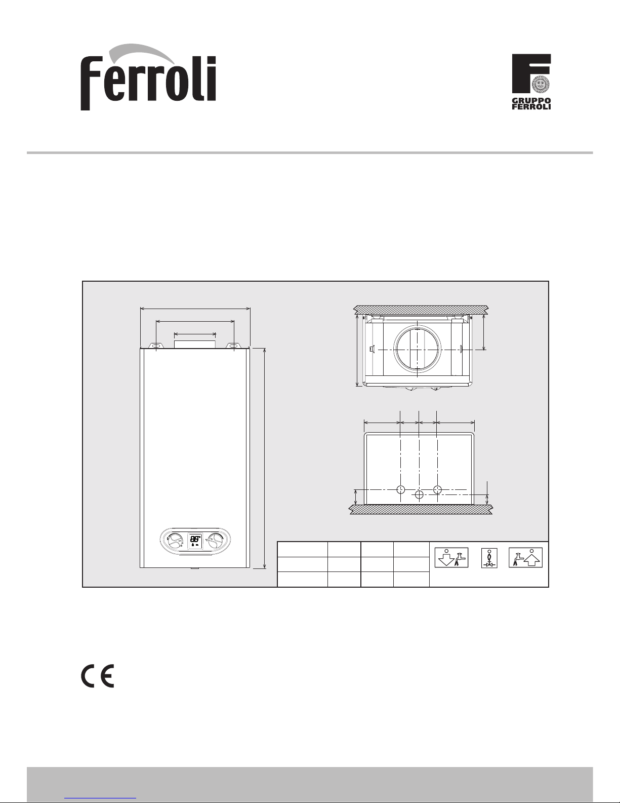
Effettuare gli allacciamenti ai corrispettivi attacchi secondo il disegno in copertina e ai
simboli riportati sull’apparecchio.
Caratteristiche dell’acqua impianto
In presenza di acqua con durezza superiore ai 25° Fr (1°F = 10ppm CaCO
3
), si prescrive
l’uso di acqua opportunamente trattata, al fine di evitare possibili incrostazioni nello scaldabagno.
3.4 Collegamento gas
L’allacciamento gas deve essere effettuato all’attacco relativo (vedi figura in copertina)
in conformità alla normativa in vigore, con tubo metallico rigido oppure con tubo flessibile
a parete continua in acciaio inox, interponendo un rubinetto gas tra impianto e scaldabagno. Verificare che tutte le connessioni gas siano a tenuta.
3.5 Condotto fumi
Il tubo di raccordo alla canna fumaria deve avere un diametro non inferiore a quello di
attacco sull'antirefouleur. A partire dall'antirefouleur deve avere un tratto verticale di lunghezza non inferiore a mezzo metro. Per quanto riguarda il dimensionamento e la posa
in opera delle canne fumarie e del tubo di raccordo ad esse, è d'obbligo rispettare le norme vigenti.
B
Lo scaldabagno è dotato di un dispositivo di sicurezza (termostato fumi) che
blocca il funzionamento dell’apparecchio in caso di cattivo tiraggio o ostruzione
della canna fumaria. Tale dispositivo non deve mai essere manomesso o disattivato.
4. SERVIZIO E MANUTENZIONE
Tutte le operazioni di regolazione, messa in servizio e quelle di controllo periodico descritte di seguito, devono essere effettuate solo da Personale Qualificato e di sicura qualificazione (in possesso dei requisiti tecnici professionali previsti dalla normativa
vigente).
FERROLI declina ogni responsabilità per danni a cose e/o persone derivanti dalla manomissione dell’apparecchio da parte di persone non qualificate e non autorizzate.
4.1 Regolazioni
Trasformazione gas di alimentazione
B
La trasformazione ad un gas differente da quello predisposto in fabbrica
deve essere realizzata da un tecnico autorizzato, utilizzando pezzi originali e in accordo con la normativa in vigore nel paese in cui si installa l’apparecchio.
L’apparecchio può funzionare con alimentazione a gas Metano o G.P.L. e viene predisposto in fabbrica per l’uso di uno dei due gas, come chiaramente riportato sull’imballo
e sulla targhetta dati tecnici dell’apparecchio stesso. Qualora si renda necessario utilizzare l’apparecchio con gas diverso da quello preimpostato, è necessario utilizzare l’apposito kit di trasformazione e operare come indicato di seguito:
fig. 5 Scollegare i cavi degli elettrodi.
fig. 5
fig. 6 Svitare le quattro viti di fissaggio del bruciatore ed estrarre il cassetto.
fig. 6
Mancata accensione del
bruciatore
Mancanza di gas
Controllare che l’afflusso di gas
alla caldaia sia regolare e che sia
stata eliminata l’aria dalle
tubazioni
Anomalia elettrodo di
rivelazione/accensione
Controllare il cablaggio
dell’elettrodo e che lo stesso sia
posizionato correttamente e privo
di incrostazioni
Valvola gas difettosa
Verificare e/o sostituire la valvola
a gas
Segnale fiamma presente
con bruciatore spento
Anomalia elettrodo
Verificare il cablaggio
dell’elettrodo di ionizzazione
Anomalia scheda Verificare e/o sostituire la scheda
Intervento protezione
sovratemperatura
Sensore riscaldamento
danneggiato o non correttamente
posizionato
Controllare il corretto
posizionamento e funzionamento
del sensore di riscaldamento e/o
sostituire
Intervento del termostato
fumi (dopo l’intervento del
termostato fumi, il funzionamento dell’apparecchio
viene riprestinato chiudendo
e riaprendo il rubinetto con
termostato raffreddato)
Contatto termostato fumi aperto Verificare il termostato
Cablaggio interrotto Verificare il cablaggio
Camino non correttamente
dimensionato oppure ostruito
Verificare la canna fumaria
Display OFF
Termostato solare aperto
Verificare o sostituire
il termostato solare
Batterie scariche Sostituire batterie
Cavi scollegati Verificare/sosituire i cavi
Il Micro (rif.
A
- fig. 9) non commuta Verificare/sosituire il micro
Il Micro di richiesta (rif.
B
- fig. 9)
non commuta
Verificare/sosituire il micro
Sonda scollegata
Verificare il collegamento o
sostituire la sonda
Page 4

SKY C B
4
IT
cod. 3541C702 - Rev. 01 - 06/2014
fig. 7 Sostituire gli ugelli al bruciatore principale, inserendo gli ugelli indicati in ta-
bella dati tecnici al cap. 5, a seconda del tipo di gas utilizzato
fig. 7
fig. 8 Estrarre le manopole di regolazione.
Svitare le due viti (1) e rimuovere la mascherina.
Svitare la vite (2) e rimuovere la centralina elettronica.
Svitare le viti (3 e 4) e rimuovere la staffa supporto mascherina.
fig. 8
fig. 9 Svitare le due viti (1), sfilare la piastrina (2) e sostituire il regolatore di po-
tenza (3).
fig. 9
fig. 10 Svitare le due viti (1) di fissaggio della valvola a gas e sostituire il cono di
modulazione (6).
Riassemblare tutti i componenti verificando che la guarnizione (7) sia ben
posizionata e che il filo di massa (4 di fig. 9) sia fissato correttamente.
Applicare la targhetta adesiva contenuta nel kit di trasformazione vicino
alla targhetta dei dati tecnici per comprovare l’avvenuta trasformazione.
fig. 10
4.2 Messa in servizio
Prima di accendere lo scaldabagno
• Verificare la tenuta dell’impianto gas.
• Riempire l’impianto idraulico ed assicurare un completo sfiato dell’aria contenuta
nello scaldabagno e nell’impianto.
• Verificare che non vi siano perdite di acqua nell’impianto o nell’apparecchio.
• Verificare che il valore di pressione gas sia quello richiesto.
• Verificare che non vi siano liquidi o materiali infiammabili nelle immediate vicinanze
dello scaldabagno.
Verifiche durante il funzionamento
• Accendere l’apparecchio.
• Assicurarsi della tenuta del circuito del combustibile e degli impianti acqua.
• Controllare l’efficienza del camino e condotto fumi durante il funzionamento dello
scaldabagno.
• Verificare la buona accensione dello scaldabagno, effettuando diverse prove di accensione e spegnimento.
• Assicurarsi che il consumo del combustibile indicato al contatore, corrisponda a
quello indicato nella tabella dati tecnici al cap. 5.
2
1
3
4
2
1
4
3
A
B
3
5
4
6
7
1
Page 5

SKY C B
5
IT
cod. 3541C702 - Rev. 01 - 06/2014
4.3 Manutenzione
Apertura del mantello
Per aprire il mantello dello scaldabagno:
1. Svitare le due viti A (vedi fig. 11).
2. Ruotare il mantello.
3. Alzare e togliere il mantello.
B
Prima di effettuare qualsiasi operazione all’interno dello scaldabagno chiudere
il rubinetto gas a monte
fig. 11 - Apertura mantello
Sostituzione batterie
Per la sostituzione delle batterie, procedere come descritto nella fig. 12.
fig. 12 - Sostituzione batterie
Controllo periodico
Per mantenere nel tempo il corretto funzionamento dell’apparecchio, è necessario far
eseguire da personale qualificato un controllo annuale che preveda le seguenti verifiche:
• I dispositivi di comando e di sicurezza devono funzionare correttamente.
• Il circuito di evacuazione fumi deve essere in perfetta efficienza.
• I condotti ed il terminale fumi devono essere liberi da ostacoli e non presentare perdite
• Il bruciatore e lo scambiatore devono essere puliti ed esenti da incrostazioni. Per
l’eventuale pulizia non usare prodotti chimici o spazzole di acciaio.
• Gli elettrodi devono essere liberi da incrostazioni e correttamente posizionati.
fig. 13 - Posizionamento elettrodi
• Gli impianti gas e acqua devono essere a tenuta.
• La portata gas e la pressione devono corrispondere a quanto indicato nelle rispettive tabelle.
5. CARATTERISTICHE E DATI TECNICI
Tabella. 3 - Legenda figure cap. 5
5.1 Vista generale e componenti principali
fig. 14 - Vista generale
A
A
1
3
2
3
±
0,5
= =
7 Entrata gas 78 Antirefouleur
8 Uscita acqua sanitaria 82 Elettrodo di rilevazione
9 Entrata acqua sanitaria 83 Centralina elettronica di comando
19 Camera combustione 126 Termostato fumi a contatto
20 Gruppo bruciatori 188 Elettrodo di accensione
27 Scambiatore in rame 358 Termostato Solare ingresso sanitario
42 Sensore di temperatura sanitario 359 Flussostato
44 Valvola gas 372 Batterie
49 Termostato di sicurezza
78
27
188
82
20
49
126
879
44
42
19
358
Page 6

SKY C B
6
IT
cod. 3541C702 - Rev. 01 - 06/2014
5.2 Schemi idraulici
fig. 15 - Circuito idraulico
5.3 Tabella dati tecnici
5.4 Schema elettrico
fig. 16
Dato Unità SKY C 11 B SKY C 14 B
Portata termica max kW 21.7 26.9 (Q)
Portata termica min kW 8.3 10.3 (Q)
Potenza Termica max kW 19.2 23.9
Potenza Termica min kW 7.1 8.8
Rendimento Pmax % 88.5 88.7
Ugelli bruciatore G20 n° x Ø 10 x 1.25 12 x 1.25
Pressione gas alimentazione G20 mbar 20.0 20.0
Portata gas max G20
m
3
/h
2.30 2.85
Portata gas min G20
m
3
/h
0.88 1.10
Ugelli bruciatore G30 n° x Ø 10 x 0.77 12 x 0.77
Pressione gas alimentazione G30 mbar 29.0 29.0
Portata gas max G30 kg/h 1.70 2.11
Portata gas min G30 kg/h 0.65 0.80
Ugelli bruciatore G31 n° x Ø 10 x 0.77 12 x 0.77
Pressione gas alimentazione G31 mbar 37 37
Portata gas max G31 kg/h 1.70 2.11
Portata gas min G31 kg/h 0.65 0.80
Pressione max esercizio bar 10 10 (PMS)
Pressione min esercizio bar 0.20 0.20
Portata sanitaria
'
t 25°C l/min 11.0 14.0
Portata sanitaria
'
t 50°C l/min 5.5 6.8 (D)
Grado protezione IP X5D X5D
Peso a vuoto kg 11 12
Tipo di apparecchio
B
11B S
PIN CE 0461CL0984
89
358
49
42
82 188
Marking
78910111213141516654321
4321
126
49
321
DISPLAY
44
359
321
358
12
_
+
372
ON/OFF
42
83
Page 7

La Direƫ va Europea 99/44/CE ha per oggeƩ o taluni aspeƫ della vendita e delle garanzie dei beni di consumo e regolamenta il rapporto tra venditore
fi nale e consumatore. La direƫ va in oggeƩ o prevede che in caso di difeƩ o di conformità del prodoƩ o, il consumatore ha diriƩ o a rivalersi nei confronƟ del
venditore fi nale per oƩ enerne il riprisƟ no senza spese, per un periodo di 24 mesi dalla data di acquisto.
Ferroli S.p.A., pur non essendo venditore fi nale nei confronƟ del consumatore, intende comunque supportare le responsabilità del venditore fi nale con una
propria Garanzia Convenzionale, fornita tramite la propria Rete di Assistenza Tecnica Autorizzata alle condizioni riportate di seguito.
OggeƩ o della Garanzia e Durata
L’ogge Ʃ o della presente garanzia convenzionale consiste nel riprisƟ no della conformità del bene senza spese per il consumatore, alle condizioni qui di
seguito specifi cate. L’Azienda produƩ rice garanƟ sce dai difeƫ di fabbricazione e di funzionamento gli apparecchi venduƟ ai consumatori, per un periodo
di 24 mesi dalla data di consegna, purché avvenuta entro 3 anni dalla data di fabbricazione del prodoƩ o e documentata aƩ raverso regolare documento
di acquisto.
La iniziale messa in servizio del prodoƩ o deve essere eī eƩ uata a cura della società installatrice o di altra diƩ a in possesso dei previsƟ requisiƟ di legge.
Entro 30 giorni dalla messa in servizio il Cliente deve richiedere ad un Centro di Assistenza Autorizzato da Ferroli S.p.A. l’intervento gratuito per la verifi ca
iniziale del prodoƩ o e l’aƫ vazione, tramite registrazione, della garanzia convenzionale. Trascorsi oltre 30 giorni dalla messa in servizio la presente Garanzia
Convenzionale non sarà più aƫ vabile.
Modalità per far valere la presente Garanzia
In caso di guasto, il Cliente deve richiedere, entro il termine di decadenza di 30 giorni, l’intervento del Centro Assistenza di zona, autorizzato Ferroli S.p.A.
I nominaƟ vi dei Centri Assistenza AutorizzaƟ sono reperibili:
• aƩ raverso il sito internet dell’Azienda produƩ rice;
• aƩ raverso il Numero Verde 800 59 60 40.
I Centri Assistenza e/o l’Azienda produƩ rice potranno richiedere di visionare il documento fi scale d’acquisto e/o il modulo/ricevuta di avvenuta aƫ vazione
della Garanzia Convenzionale Ɵ mbrato e fi rmato da un Centro Assistenza Autorizzato; conservare con cura tali documenƟ per tuƩ a la durata della
garanzia.
I cosƟ di intervento sono a carico dell’Azienda produƩ rice, faƩ e salve le esclusioni previste e riportate nel presente CerƟfi cato. Gli intervenƟ in garanzia non
modifi cano la data di decorrenza della garanzia e non prolungano la durata della stessa.
Esclusioni
Sono esclusi dalla presente garanzia i difeƫ di conformità causaƟ da:
• trasporto non eī eƩ uato a cura dell’azienda produƩ rice;
• anormalità o anomalie di qualsiasi genere nell’alimentazione degli impianƟ idraulici, eleƩ rici, di erogazione del combusƟ bile, di camini e/o scarichi;
• calcare, inadeguaƟ traƩ amenƟ dell’acqua e/o traƩ amenƟ disincrostanƟ erroneamente eī eƩ uaƟ ;
• corrosioni causate da condensa o aggressività d’acqua;
• gelo, correnƟ vaganƟ e/o eī eƫ dannosi di scariche atmosferiche;
• mancanza di disposiƟ vi di protezione contro le scariche atmosferiche;
• trascuratezza, incapacità d’uso o manomissioni/modifi che eī eƩ uate da personale non autorizzato;
• cause di forza maggiore indipendenƟ dalla volontà e dal controllo dell’Azienda produƩ rice.
E’ esclusa qualsiasi responsabilità dell’Azienda produƩ rice per danni direƫ e/o indireƫ , a qualsiasi Ɵ tolo dovuƟ .
La presente Garanzia Convenzionale decade nel caso di:
• assenza del documento fi scale d’acquisto e/o del modulo/ricevuta di avvenuta aƫ vazione della Garanzia Convenzionale Ɵ mbrato e fi rmato dal Centro
Assistenza Autorizzato;
• inosservanza delle istruzioni e delle avvertenze previste dall’azienda produƩ rice e riportate sui manuali di uƟ lizzo a corredo del prodoƩ o;
• errata installazione o inosservanza delle prescrizioni di installazione, previste dall’azienda produƩ rice e riportate sui manuali di installazione a corredo
del prodoƩ o;
• inosservanza di norme e/o disposizioni previste da leggi e/o regolamenƟ vigenƟ , in parƟ colare per assenza o difeƩ o di manutenzione periodica;
• intervenƟ tecnici eī eƩ uaƟ sul prodoƩ o da soggeƫ estranei alla Rete di Assistenza Autorizzata dall’Azienda produƩ rice;
• impiego di parƟ di ricambio non originali Ferroli S.p.A.
Non rientrano nella presente Garanzia Convenzionale la sosƟ tuzione delle parƟ soggeƩ e a normale usura di impiego (anodi, guarnizioni, manopole,
lampade spia, resistenze eleƩ riche, ecc..), le operazioni di pulizia e manutenzione ordinaria e le eventuali aƫ vità od operazioni per accedere al prodoƩ o
(smontaggio mobili o coperture, allesƟ mento ponteggi, noleggio gru/cestelli, ecc..)
Responsabilità
Il personale autorizzato dall’Azienda produƩ rice interviene a Ɵ tolo di assistenza tecnica nei confronƟ del Cliente; l’installatore resta comunque l’unico
responsabile dell’installazione che deve rispeƩ are le prescrizioni di legge e le prescrizioni tecniche riportate sui manuali di installazione a corredo del
prodoƩ o.
Le condizioni di Garanzia Convenzionale qui elencate sono le uniche oī erte da Ferroli S.p.A.. Nessun terzo è autorizzato a modifi care i termini della
presente garanzia né a rilasciarne altri verbali o scriƫ .
Diriƫ di legge
La presente Garanzia Convenzionale si aggiunge e non pregiudica i diriƫ del consumatore previsƟ dalla direƫ va 99/44/CEE e relaƟ vo decreto nazionale
di aƩ uazione D. Lgs. 06/09/2005 n. 206. Qualsiasi controversia relaƟ va alla presente garanzia sarà devoluta alla competenza esclusiva del Tribunale di
Verona.
CerƟfi cato di Garanzia
La presente garanzia convenzionale è valida per gli apparecchi desƟ naƟ alla
commercializzazione, venduƟ ed installaƟ sul solo territorio italiano
CerƟfi cato di Garanzia CerƟfi cato di Garanzia CerƟfi cato di Garanzia CerƟfi
c
CerƟfi cato di Garanzia CerƟfi cato di Garanzia CerƟfi cato di Garanzia CerƟfi
c
FERROLI S.p.A. - Via Ritonda 78/a - 37047 San Bonifacio (Verona) Italy - tel. +39.045.6139411 - fax. +39.045.6100933 - www.ferroli.it
Page 8

SKY C B
8
EN
cod. 3541C702 - Rev. 01 - 06/2014
EN
1. GENERAL INSTRUCTIONS
• Carefully read and follow the instructions contained in this booklet.
• After installing the unit, inform the user about its operation and give him this manual, which
is an integral and essential part of the product and must be kept for future reference.
• Installation and maintenance must be carried out by professionally qualified personnel, in
compliance with the current regulations and according to the manufacturer's instructions.
Do not carry out any operation on sealed adjustment parts.
• Incorrect installation or inadequate maintenance can result in damage or injury. The Manufacturer declines any liability for damage due to errors in installation and use, or failure to
follow the instructions.
• Before carrying out any cleaning or maintenance operation, turn off the gas by means of
the special shutoff devices.
• In case of a fault and/or poor operation, deactivate the unit and do not try to repair it or
directly intervene. Contact professionally qualified personnel. Any repair/replacement of
the products must only be carried out by qualified personnel using original replacement
parts. Failure to comply with the above could affect the safety of the unit.
• This unit must only be used for its intended purpose. Any other use is deemed improper
and therefore hazardous.
• The packing materials are potentially hazardous and must not be left within the reach of
children.
• The unit must not be used by people (including children) with limited physical, sensory or
mental abilities or without experience and knowledge of it, unless instructed or supervised
in its use by someone responsible for their safety.
• The unit and its accessories must be appropriately disposed of, in compliance with the current regulations.
• The images given in this manual are a simplified representation of the product. In this representation there may be slight and insignificant differences with respect to the product
supplied.
2. OPERATING INSTRUCTIONS
2.1 Introduction
SKY C B is a high efficiency, instantaneous domestic hot water heater using natural gas
or propane gas, equipped with an open-flue burner with electronic ignition, battery powered, intended for indoor installation.
2.2 Control panel
Panel
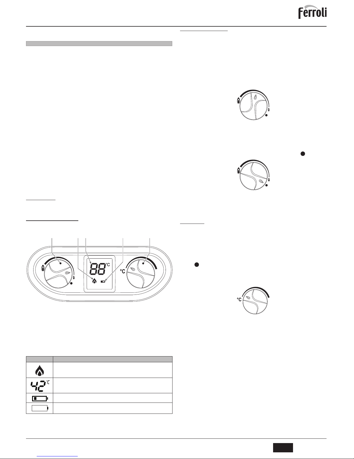
fig. 1 - Control panel
Panel legend fig. 1
1 DHW temperature display
2 Battery level signalling
3 Off/burner power adjustment
4 Temperature adjustment
5 Flame symbol
Indication during operation
Table. 1 - Display symbols
During a DHW demand (generated by drawing hot water), the display shows the actual
DHW outlet temperature.
2.3 Lighting and shutdown
Preliminary operations and checks
1. Make sure the hot water taps are closed.
2. Open the water heater gas supply cock, located on its gas connection.
3. Make sure the 1.5 V batteries are properly fitted, with the correct polarity (+ and -).
For their replacement see *** 'Replacing batteries' on page 11 ***.
4. Also make sure the batteries have enough charge for water heater operation.
Lighting
Turn the knob to the required water heating level.
fig. 2 - Lighting
The unit will immediately be ready to work whenever hot water is drawn.
Turning off
The burner goes off automatically when the demand for hot water ceases.
No particular operation is required in order to do another lighting phase.
To shut down unit, turn the knob to .
fig. 3 - Unit deactivated
In case of a prolonged shutdown, close the gas cock ahead of the unit.
B
To avoid damage caused by freezing during long shutdowns in winter, it is advisable to drain all water from the water heater.
2.4 Adjustments
Manual setting of burner power
Use the power adjustment knob (ref. 3 - fig. 1) to select the water heater power, minimum
or maximum and intermediate positions depending on the required water heating level.
Turn the knob anticlockwise and the unit heats the water at maximum power. If the temperature is too high, for example in the summer, or when a reduced flow of not very hot
water is necessary, turn the knob clockwise. This reduces the power (and gas consumption). In the position the unit is deactivated.
Setting the temperature
The water temperature can be easily set with the temperature selector: turn it to the right
to increase the temperature, or to the left to decrease it.
fig. 4 - Temperature adjustment
Faults
After making the above adjustments, the water heater will be ready to work in completely
automatic mode. When a hot water tap is turned on, an intermittent discharge is generated on the ignition electrode, which causes lighting of the burner.
All electronic models have an ionisation electrode fitted in the burner to control the correct presence of flame. In case of a fault or no gas feed with consequent burner shutdown, the hot water tap must be turned off.
It is therefore necessary to eliminate the cause of no gas reaching the water heater, e.g.
inadvertent closing of the gas cock, gas cylinder empty, etc.
Water heater shutdown is deactivated by turning the hot water tap off and on.
Repeat the operation if there is still no hot water after eliminating the cause and turning
on the hot water tap. If the problem persists, contact the After-Sales Service.
Symbol flashing: the burner is lit.
If the burner is off, this symbol is not displayed.
Temperature of water at the water heater outlet.
Symbol steady. The battery is nearly flat. Replacement is recommended.
Symbol flashing. The battery is flat and needs replacing.
12345
Page 9
SKY C B
9
EN
cod. 3541C702 - Rev. 01 - 06/2014
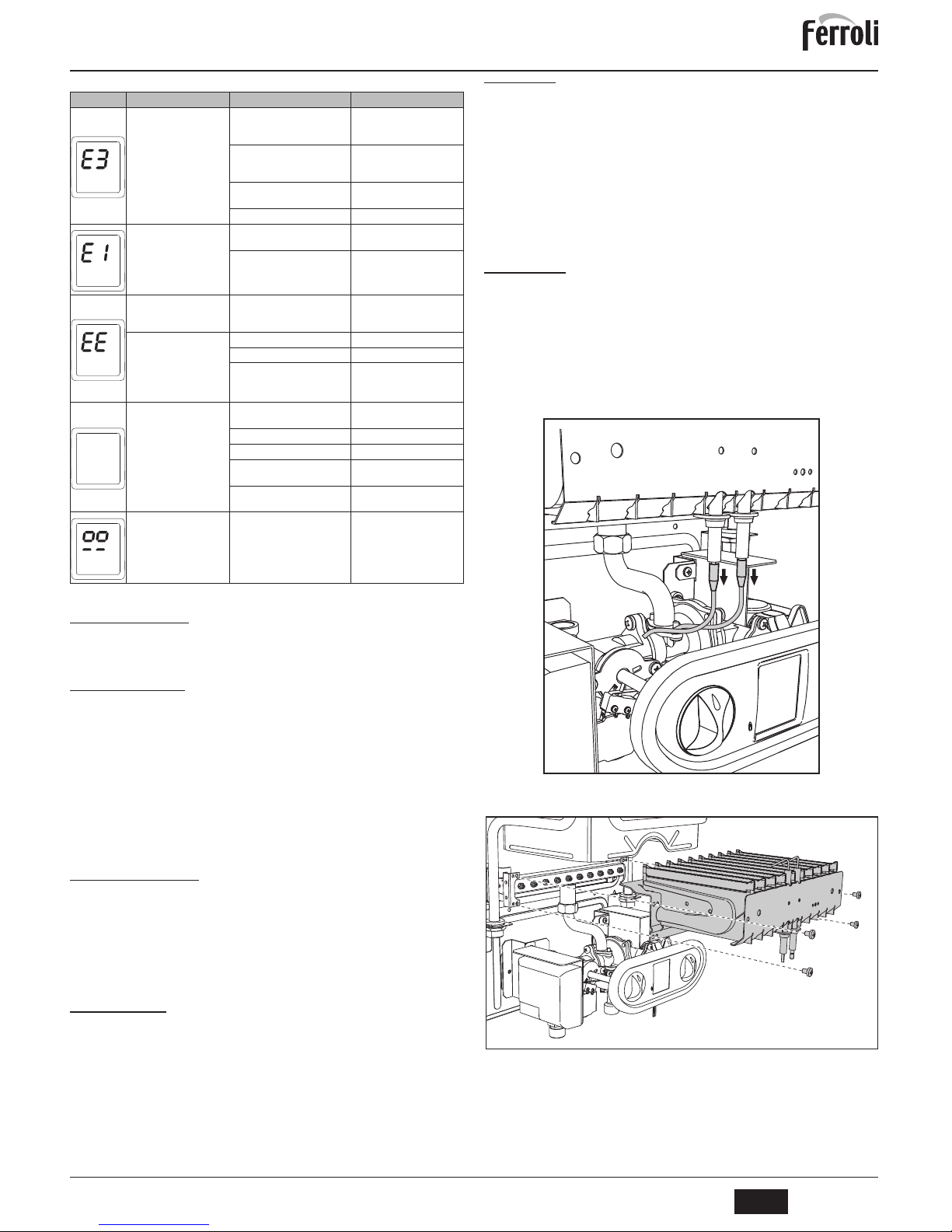
Table. 2 - Table of faults
3. INSTALLATION
3.1 General Instructions
THE WATER HEATER MUST ONLY BE INSTALLED BY QUALIFIED PERSONNEL, IN
COMPLIANCE WITH ALL THE INSTRUCTIONS GIVEN IN THIS TECHNICAL MANUAL, THE PROVISIONS OF CURRENT LAW, THE NATIONAL AND LOCAL REGULATIONS, AND THE RULES OF PROPER WORKMANSHIP.
3.2 Place of installation
This unit is an “open chamber” type and can only be installed and operated in permanently ventilated rooms. An insufficient supply of combustion air to the water heater will
affect its normal operation and the evacuation of fumes. Also, the fumes forming in these
conditions are extremely harmful to the health if dispersed in the domestic environment.
Make sure the room where the unit is to be installed meets all the conditions required by
the Current Regulations.
In any case, the place of installation must be free of dust, flammable materials or objects
or corrosive gases.
Place the water heater as close as possible to the hot water taps, near the sink, but NEV-
ER above a cooktop. It must also be located as close as possible to the flue or the place
from where the fume exhaust pipe starts.
A
If the unit is enclosed in a cabinet or mounted alongside, a space must be provided for removing the casing and for normal maintenance operations.
3.3 Plumbing connections
Important
B
Before making the connection, check that the unit is arranged for operation with
the type of fuel available and carefully clean all the system pipes.
Carry out the relevant connections according to the cover diagram and the symbols given on the unit .
System water characteristics
In the presence of water harder than 25° Fr (1°F = 10ppm CaCO
3
), use suitably treated
water in order to avoid possible scaling in the water heater.
3.4 Gas connection
The gas must be connected to the respective union (see figure on cover) in conformity
with the current regulations, with a rigid metal pipe or with a continuous flexible s/steel
tube, installing a gas cock between the system and water heater . Make sure all the gas
connections are tight.
3.5 Fume duct
The diameter of the connecting pipe to the flue must not be less than that of the connection on the anti-backflow device. Starting from the anti-backflow device it must have a
vertical section at least 50 cm long. The current regulations must be respected regarding
the dimensioning and installation of the flues and connection pipe.
B
The water heater has a safety device (fume thermostat) that stops unit operation in case of poor draught or obstruction of the flue. This device must never
be tampered with or deactivated.
4. SERVICE AND MAINTENANCE
All adjustment, system start-up and periodical inspection operations described hereunder must be carried out solely by Qualified Personnel (with the professional technical requirements prescribed by current regulations).
FERROLI declines any liability for damage and/or injury caused by unqualified and unauthorised persons tampering with the unit.
4.1 Adjustments
Gas conversion
B
Conversion to a gas different from that for which the unit is arranged
must be done by an authorised technician, using original parts and in
compliance with the regulations in force in the country where the unit is
installed.
The unit can operate on natural gas or LPG and is factory-set for use with one of these
two gases, as clearly shown on the packing and on the data plate. Whenever a gas different from that for which the unit is arranged has to be used, the special conversion kit
will be required, proceeding as follows:
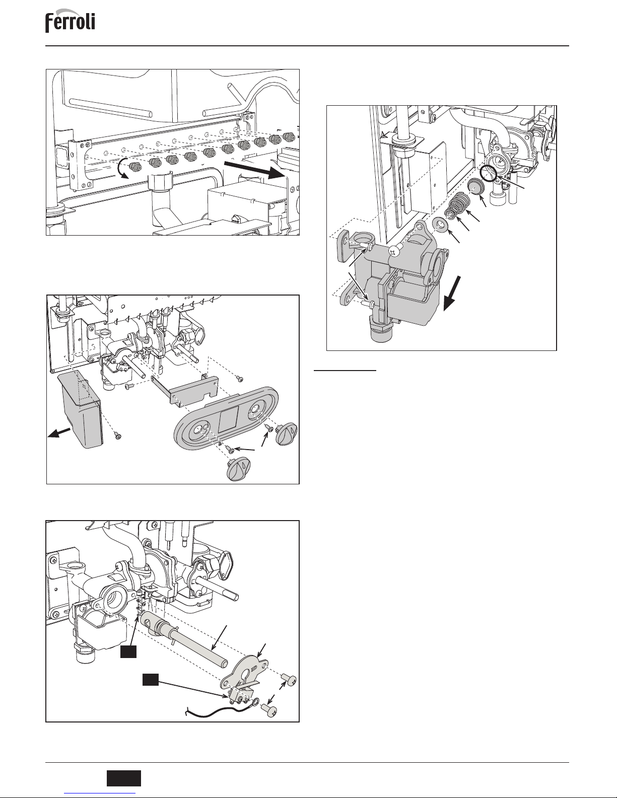
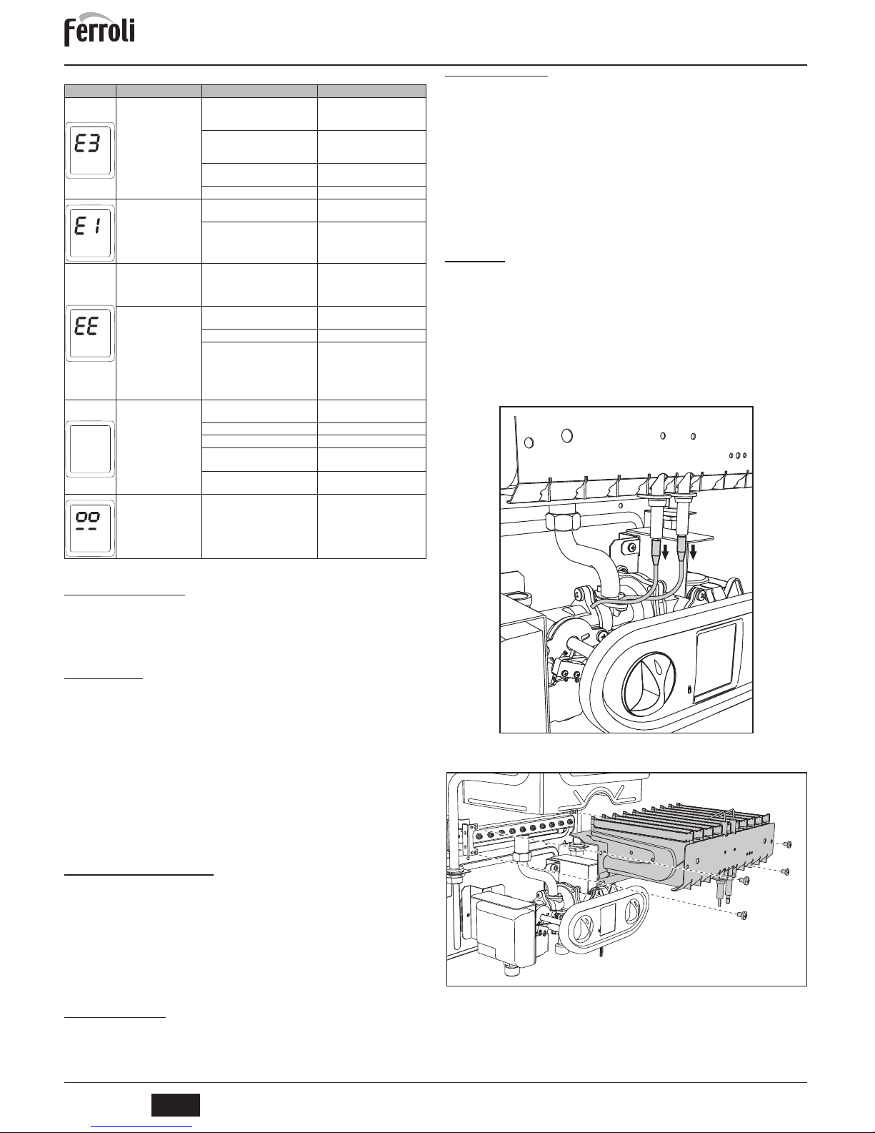
fig. 5 Disconnect the wires of the electrodes.
fig. 5
fig. 6 Undo the four screws fixing the burner and pull out the tray.
fig. 6
No burner ignition
No gas
Check the regular gas flow to the
boiler and that the air has been
eliminated from the pipes
Ignition/detection electrode fault
Check the wiring of the electrode
and that it is correctly positioned
and free of any deposits
Faulty gas valve
Check and/or replace
the gas valve
Flame present signal with
burner off
Electrode fault
Check the ionisation electrode
wiring
Card fault Check and/or replace the card
Overtemperature protection
activation
Heating sensor damaged or not
correctly positioned
Check the correct positioning
and operation of the heating
sensor and/or replace it
Intervention of the fume
thermostat (after intervention
of the fume thermostat, unit
operation is restored by turning the tap off and then on
again with thermostat cooled)
Fume thermostat contact open Check the thermostat
Wiring disconnected Check the wiring
Flue obstructed or not correctly
sized
Check the flue
Display OFF
Solar thermostat open
Check or replace the solar
thermostat
Batteries flat Replace the batteries
Cables disconnected Check/replace the cables
The microswitch (ref.
A
- fig. 9)
does not commutate
Check/replace the microswitch
The demand microswitch
(ref.
B
- fig. 9) does not commutate
Check/replace the microswitch
Probe disconnected
Check the connection or replace
the probe
Page 10
SKY C B
10
EN
cod. 3541C702 - Rev. 01 - 06/2014
fig. 7 Replace the nozzles at the main burner, fitting the nozzles specified in the
technical data table in cap. 5, according to the type of gas used
fig. 7
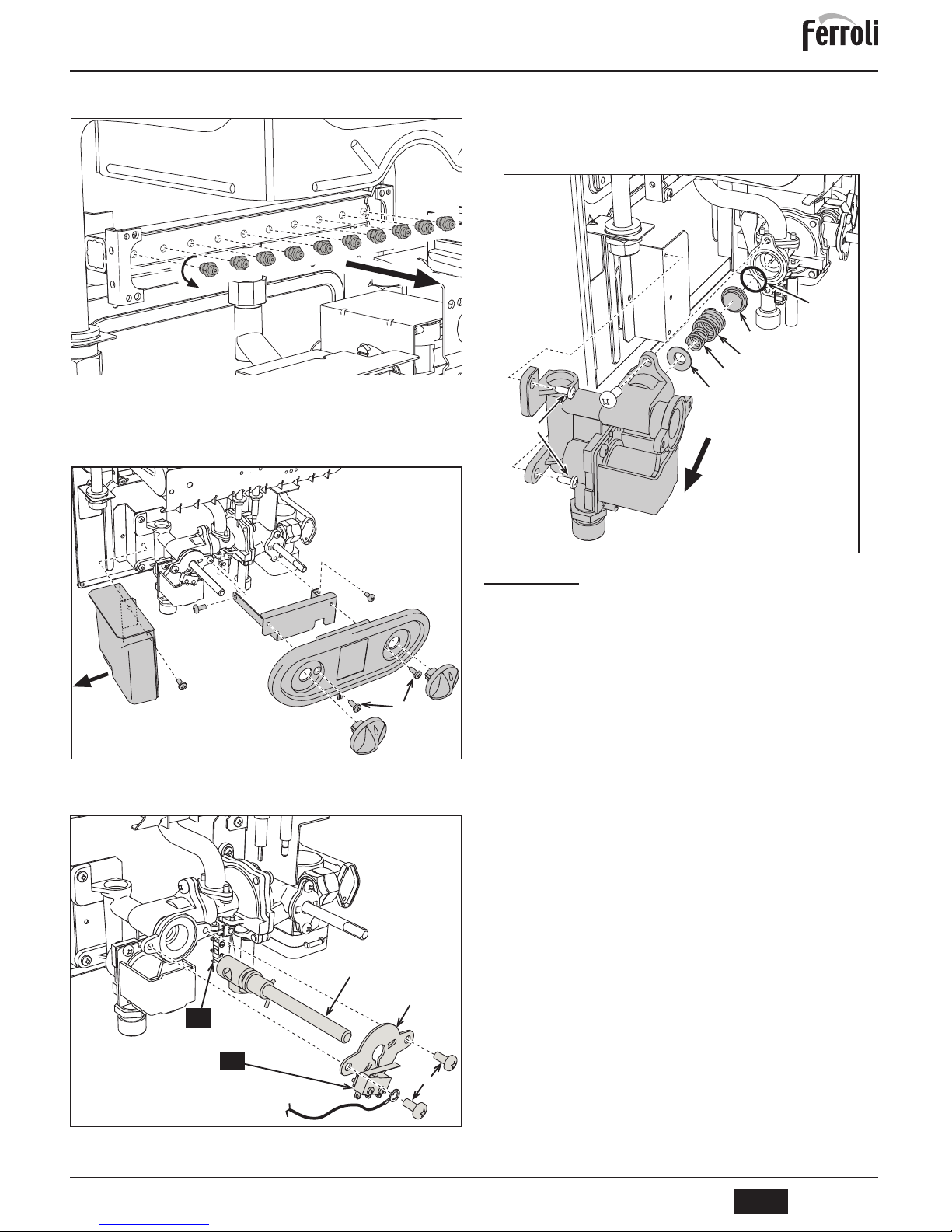
fig. 8 Pull out the adjustment knobs.
Undo the two screws (1) and remove the cover.
Undo the screw (2) and remove the electronic controller.
Undo the screws (3 and 4) and remove the cover support bracket.
fig. 8
fig. 9 Undo the two screws (1), pull out the plate (2) and replace the power reg-
ular (3).
fig. 9
fig. 10 Undo to two screws (1) fixing the gas valve and replace the modulation
cone (6).
Refit all the parts, making sure the gasket (7) is in place and that the earth
wire (4 of fig. 9) is properly fixed.
Apply the sticker contained in the conversion kit, near the data plate as
proof of the conversion.
fig. 10
4.2 Commissioning
Before lighting the water heater
• Check the tightness of the gas system.
• Fill the hydraulic system and make sure the air in the water heater and system is
completely vented.
• Make sure there are no water leaks in the system and unit.
• Check the correct gas pressure value.
• Make sure there are no flammable liquids or materials in the immediate vicinity of
the water heater.
Checks during operation
• Turn the unit on.
• Check the tightness of the fuel circuit and water systems.
• Check the efficiency of the flue and fume ducts when the water heater is operating.
• Check correct lighting of the water heater by turning it on and off several times.
• Make sure the fuel consumption indicated on the meter matches that given in the
technical data table on cap. 5.
2
1
3
4
2
1
4
3
A
B
3
5
4
6
7
1
Page 11
SKY C B
11
EN
cod. 3541C702 - Rev. 01 - 06/2014
4.3 Maintenance
Opening the casing
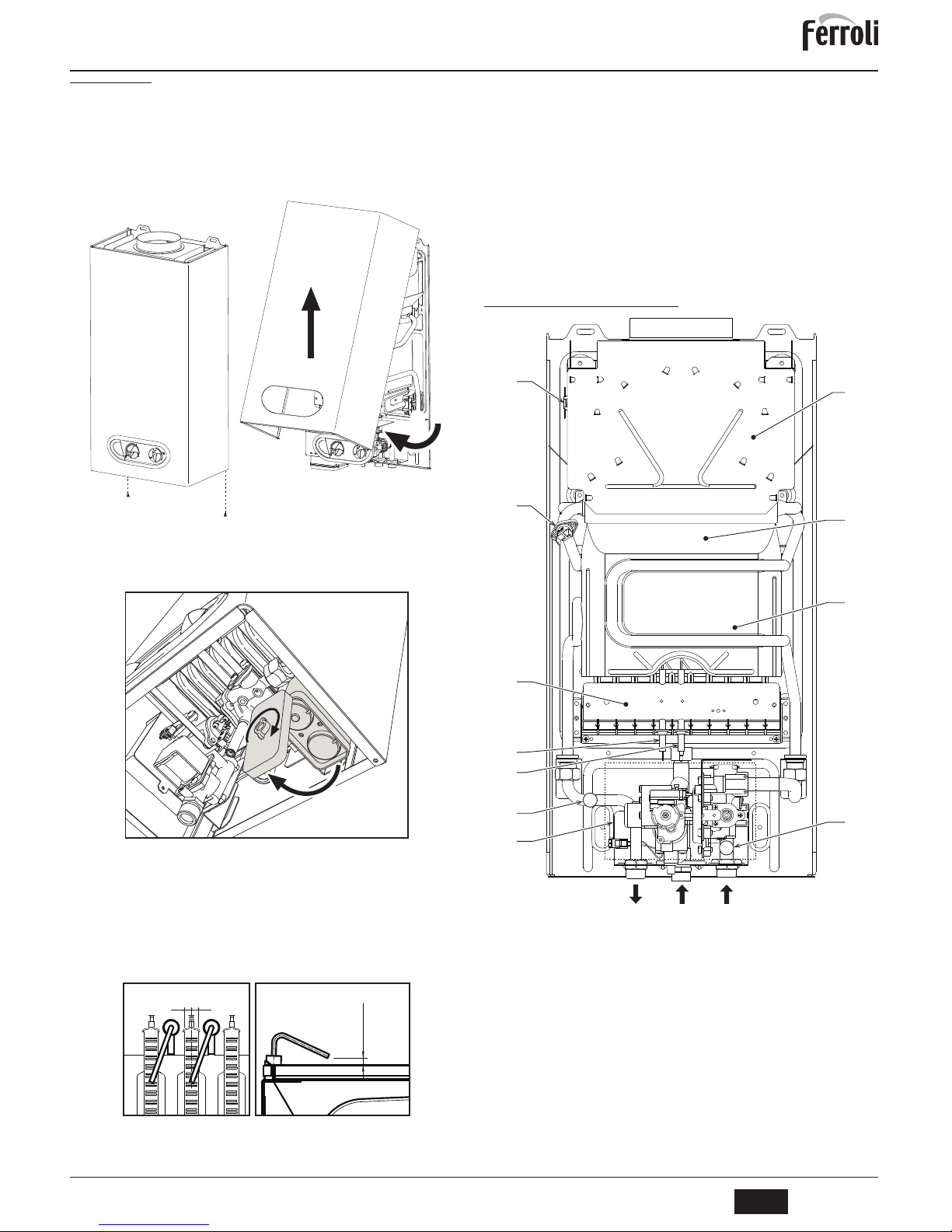
To open the water heater casing:
1. Undo the two screws A (see fig. 11).
2. Turn the casing.
3. Lift and remove the casing.
B
Close the gas cock upstream before carrying out any operation inside the water
heater
fig. 11 - Opening the casing
Replacing batteries
To replace the batteries, proceed as described in fig. 12.
fig. 12 - Replacing batteries
Periodical inspection
To ensure proper operation of the unit over time, have qualified personnel carry out a
yearly inspection, providing for the following checks:
• The control and safety devices must work properly.
• The fume exhaust circuit must be perfectly efficient.
• The fume ducts and terminal must be free of any obstacles and leaks
• The burner and exchanger must be clean and free of deposits. For possible cleaning, do not use chemical products or wire brushes.
• The electrodes must be free of deposits and correctly positioned.
fig. 13 - Electrode positioning
• The gas and water systems must be tight.
• The gas flow and pressure must match that given in the respective tables.
5. TECHNICAL DATA AND CHARACTERISTICS
Table. 3 - Key of figures cap. 5
5.1 General view and main components
fig. 14 - General view
A
A
1
3
2
3
±
0,5
= =
7 Gas inlet 78 Anti-backflow device
8 Domestic hot water outlet 82 Detection electrode
9 Cold water inlet 83 Electronic controller
19 Combustion chamber 126 Contact fume thermostat
20 Burner assembly 188 Ignition electrode
27 Copper exchanger 358 DHW inlet Solar thermostat
42 DHW temperature sensor 359 Flow switch
44 Gas valve 372 Battery
49 Safety thermostat
78
27
188
82
20
49
126
879
44
42
19
358
Page 12
SKY C B
12
EN
cod. 3541C702 - Rev. 01 - 06/2014
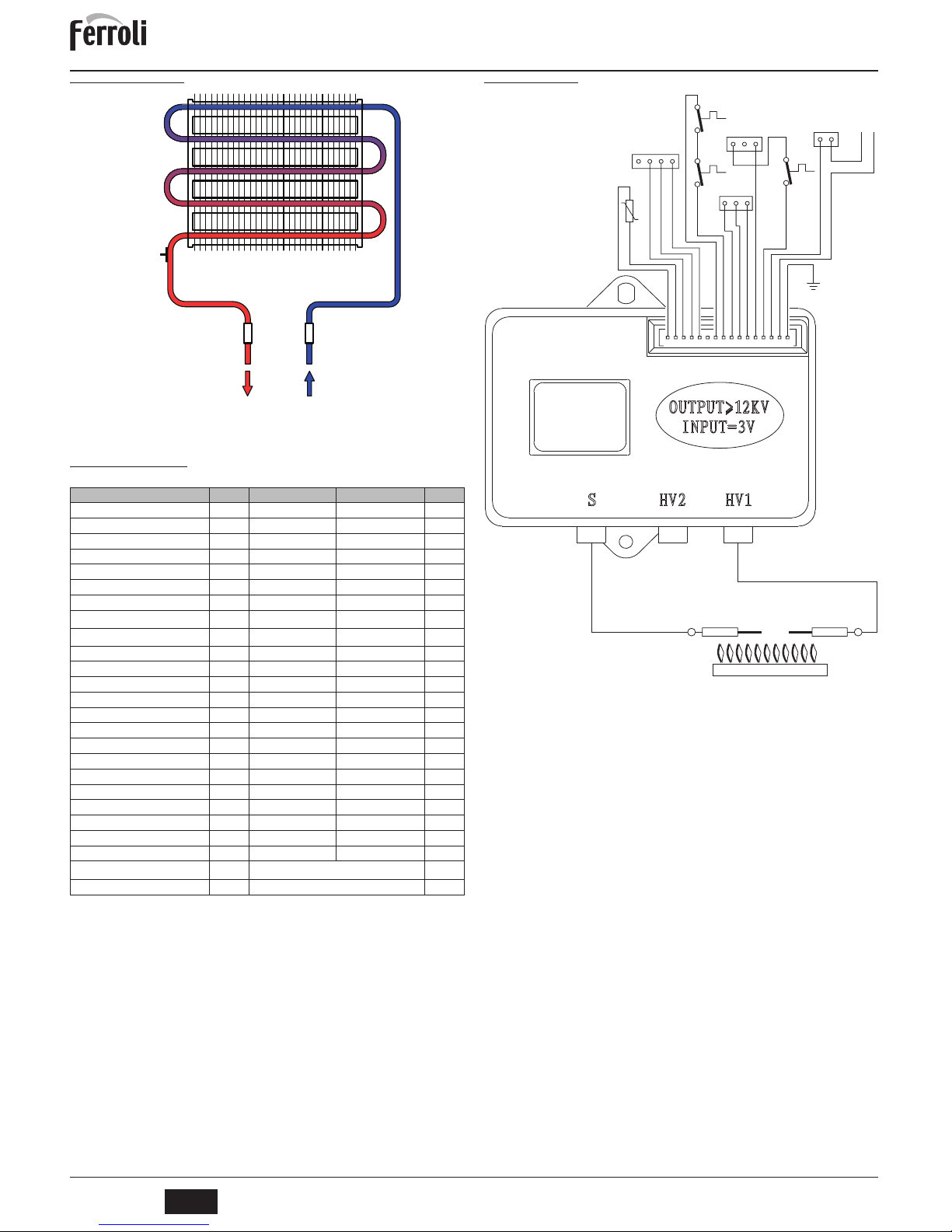
5.2 Hydraulic diagrams
fig. 15 - Water circuit
5.3 Technical data table
5.4 Wiring diagram
fig. 16
Data Unit SKY C 11 B SKY C 14 B
Max. heating capacity kW 21.7 26.9 (Q)
Min. heating capacity kW 8.3 10.3 (Q)
Max. heat output kW 19.2 23.9
Min. heat output kW 7.1 8.8
Pmax efficiency % 88.5 88.7
Burner nozzles G20 no. x Ø 10 x 1.25 12 x 1.25
Gas supply pressure G20 mbar 20.0 20.0
Max. gas delivery G20
m
3
/h
2.30 2.85
Min. gas delivery G20
m
3
/h
0.88 1.10
Burner nozzles G30 no. x Ø 10 x 0.77 12 x 0.77
Gas supply pressure G30 mbar 29.0 29.0
Max. gas delivery G30 kg/h 1.70 2.11
Min. gas delivery G30 kg/h 0.65 0.80
Burner nozzles G31 no. x Ø 10 x 0.77 12 x 0.77
Gas supply pressure G31 mbar 37 37
Max. gas delivery G31 kg/h 1.70 2.11
Min. gas delivery G31 kg/h 0.65 0.80
Max. operating pressure bar 10 10 (PMS)
Min. working pressure bar 0.20 0.20
DHW flow rate
'
t 25°C l/min 11.0 14.0
DHW flow rate
'
t 50°C l/min 5.5 6.8 (D)
Protection rating IP X5D X5D
Empty weight kg 11 12
Type of unit
B
11B S
PIN CE 0461CL0984
89
358
49
42
82 188
Marking
78910111213141516654321
4321
126
49
321
DISPLAY
44
359
321
358
12
_
+
372
ON/OFF
42
83
Page 13
SKY C B
13
FR
cod. 3541C702 - Rev. 01 - 06/2014
FR
1. GÉNÉRALITÉS
• Lire attentivement et respecter les avertissements contenus dans le présent livret d'instructions.
• Après l'installation de l'appareil, l'installateur doit informer l'utilisateur sur son fonctionnement et lui remettre le présent livret qui fait partie intégrante et essentielle du produit ; en
outre, ce livret doit être conservé avec soin pour toute consultation future.
• L'installation et l'entretien doivent être effectués conformément aux normes en vigueur, selon les instructions du constructeur et par des techniciens qualifiés. Toute opération sur
les organes de réglage scellés est interdite.
• Une installation incorrecte ou un entretien impropre peuvent entraîner des dommages corporels ou matériels. Le constructeur n'assume aucune responsabilité pour les dommages
causés par des erreurs d'installation et d'utilisation et, dans tous les cas, en cas de non
observance des instructions.
• Avant de nettoyer ou de procéder à la maintenance de l'appareil, fermer les robinets du
gaz.
• Désactiver l'appareil en cas de panne et/ou de mauvais fonctionnement en s'abstenant de
toute tentative de réparation ou d'intervention directe. S'adresser uniquement à un technicien professionnel qualifié. Les éventuelles réparations ou remplacements de composants
sont réservés exclusivement à un technicien professionnel qualifié en n'utilisant que des
pièces de rechange d'origine. La non-observance de ce qui précède compromet les conditions de sécurité de l'appareil.
• Cet appareil ne peut servir que dans le cadre des utilisations pour lesquelles il a été conçu.
Tout autre usage doit être considéré comme impropre et donc dangereux.
• Les éléments de l'emballage ne peuvent être laissés à la portée des enfants du fait qu'ils
pourraient représenter une source potentielle de danger.
• Cet appareil n’est pas prévu pour être utilisé par des personnes (y compris les enfants)
dont les capacités physiques, sensorielles ou mentales sont réduites, ou des personnes
dénuées d’expérience ou de connaissance, sauf si elles ont pu bénéficier, par l’intermédiaire d’une personne responsable de leur sécurité, d’une surveillance ou d’instructions
préalables concernant l’utilisation de l’appareil.
• Mettre l'appareil et ses accessoires au rebut conformément aux normes en vigueur.
• Les images contenues dans ce manuel ne sont qu'une représentation simplifiée de l'appareil. Cette représentation peut présenter de légères différences, non significatives, par
rapport à l'appareil.
2. CONSIGNES D'UTILISATION
2.1 Introduction
SKY C B est un chauffe-eau instantané pour la production d'eau chaude sanitaire à haut
rendement fonctionnant au gaz naturel ou au gaz propane, doté d'un brûleur atmosphérique à allumage électronique, alimenté par une batterie, pour l’installation intérieure.
2.2 Tableau des commandes
Panneau
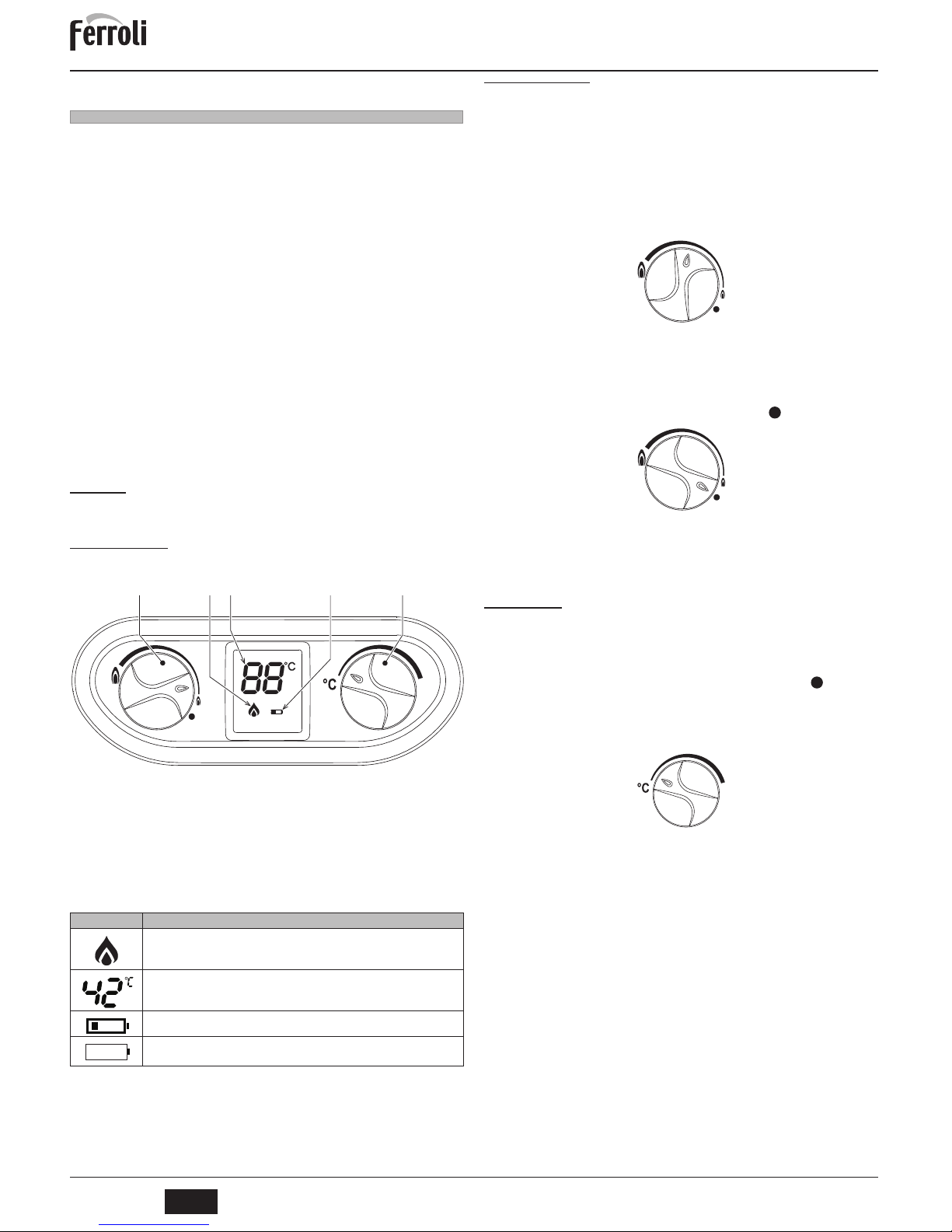
fig. 1 - Panneau de contrôle
Légende panneau fig. 1
1 Affichage de la température eau chaude sanitaire
2 Signalisation niveau de charge des batteries
3 Régulation puissance du brûleur/off
4 Régulation de la température
5 Symbole de la flamme
Indication durant le fonctionnement
Tableau 1 - Symboles d'affichage
Durant la demande ECS (par prélèvement d'ECS), l'afficheur visualise la température
actuelle de l'eau sur la sortie ECS.
2.3 Allumage et extinction
Vérifications et opérations préliminaires
1. S'assurer que les robinets de l'eau chaude sont fermés.
2. Ouvrir le robinet d'arrivée du gaz au chauffe-eau, sur le raccordement du gaz à l'appareil.
3. S'assurer que les batteries de 1,5 V sont installées dans leur logement dans le bon
sens (attention aux pôles + et -).
Pour les remplacer, voir *** 'Remplacement des batteries' on page 16 ***.
4. S'assurer que les batteries ont une charge suffisante pour permettre le fonctionnement du chauffe-eau.
Allumage
Tourner le bouton sur la position indiquant la température choisie pour l'eau.
fig. 2 - Allumage
L'appareil se déclenchera chaque fois qu'il y aura demande d'eau chaude sanitaire.
Extinction
Le brûleur s'éteint automatiquement dès que la demande d'ECS cesse.
Aucune opération spéciale n'est nécessaire pour lancer une nouvelle phase d'allumage.
Pour éteindre complètement l'appareil, tourner le bouton sur la position .
fig. 3 - Appareil désactivé
En cas d'arrêt prolongé, fermer le robinet du gaz en amont de l'appareil.
B
Pour les arrêts prolongés en hiver et afin d'éviter les dommages causés par le
gel, il est conseillé de purger toute l'eau contenue dans le chauffe-eau.
2.4 Réglages
Configuration manuelle de la puissance du brûleur
Le bouton de régulation de la puissance (rep. 3 - fig. 1) permet de sélectionner la puissance du chauffe-eau - minimum ou maximum et positions intermédiaires - en fonction
de la température de l'eau que l'on souhaite obtenir. Tourner le bouton dans le sens inverse des aiguilles d'une montre pour que l'appareil chauffe l'eau à la puissance maximum. Si la température s'avère trop élevée, surtout l'été, ou en cas de nécessité d'un
débit réduit d'eau moyennement chaude, tourner le bouton dans le sens des aiguilles
d'une montre. Ceci permet de réduire la puissance (et la consommation de gaz). Sur la
position l'appareil est désactivé.
Programmation de la température
Le sélecteur de température permet de programmer facilement la température de l'eau
: le tourner à droite pour augmenter la température ou à gauche pour la réduire.
fig. 4 - Réglage de la température
Anomalies
Une fois les réglages terminés, le chauffe-eau est prêt pour fonctionner en mode automatique. Dès que l'on tourne le robinet de l'eau chaude, l'électrode d'allumage subit une
décharge intermittente qui détermine l'allumage du brûleur.
Tous les modèles électroniques disposent d'une électrode de ionisation insérée dans le
brûleur pour contrôler la présence de la flamme. En cas d'anomalie ou d'absence d'alimentation en gaz entraînant l'extinction du brûleur, fermer le robinet de l'eau chaude.
Résoudre le problème en cherchant l'élément qui empêche l'arrivée du gaz au chauffeeau. Le robinet du gaz pourrait être fermé ou la bouteille de gaz pourrait être vide, etc..
Pour débloquer le chauffe-eau, fermer et rouvrir le robinet de l'eau chaude.
Si l'eau reste froide après avoir éliminé le problème, répéter l'opération. Si l'anomalie
persiste, s'adresser au Service d'Assistance technique.
Symbole clignotant : le brûleur est allumé.
Si le brûleur est éteint, ce symbole ne s'affiche pas.
Température de l'eau à la sortie du chauffe-eau.
Symbole allumé. La batterie est presque à plat. Il est recommandé de la remplacer.
Symbole clignotant. La batterie est à plat. La remplacer.
12345
Page 14
SKY C B
14
FR
cod. 3541C702 - Rev. 01 - 06/2014
Tableau 2 - Tableau des anomalies
3. INSTALLATION
3.1 Dispositions générales
L'INSTALLATION DU CHAUFFE-BAIN EST RÉSERVÉE À DES TECHNICIENS SPÉCIALISÉS ET QUALIFIÉS, DISPOSANT DU SAVOIR-FAIRE REQUIS ET DANS LA
STRICTE OBSERVANCE DES INSTRUCTIONS DU PRÉSENT MANUEL, DES DISPOSITIONS LÉGALES APPLICABLES ET DES NORMES NATIONALES ET LOCALES ÉVENTUELLES, CONFORMÉMENT AUX RÈGLES DE LA BONNE PRATIQUE
TECHNIQUE ET PROFESSIONNELLE.
3.2 Emplacement
Cet appareil est du type “à chambre ouverte” et ne peut être installé et fonctionner que
dans des locaux suffisamment aérés. Un apport insuffisant d'air comburant au chauffeeau peut en compromettre le bon fonctionnement ainsi que l'évacuation des fumées. En
outre, les produits de combustion qui se seraient formés en de telles conditions nuiraient
gravement à la santé en se propageant dans l'air ambiant de l'habitation.
S'assurer que le local dans lequel doit être installé l'appareil présente toutes les conditions nécessaires dictées par les normes en vigueur.
Le lieu d'installation doit être exempt de toute poussière, d'objets ou de matériaux inflammables ainsi que de gaz corrosifs.
Installer le chauffe-eau le plus près possible des robinets de l'eau chaude, à proximité de
l'évier, mais
JAMAIS
au-dessus du plan de cuisson. L'installer également le plus près pos-
sible du conduit de fumée ou au point de départ du tuyau d'évacuation des gaz brûlés.
A
Si l'appareil est monté interposé entre deux meubles ou en juxtaposition de
ceux-ci, prévoir de l'espace pour le démontage de l'habillage et pour l'entretien
normal.
3.3 Raccordements hydrauliques
Avertissements
B
Avant d'effectuer le raccordement, veiller à ce que l'appareil soit préparé pour
fonctionner avec le type de combustible disponible et prendre soin de bien nettoyer les conduites du circuit.
Effectuer les raccordements aux points prévus, comme le montre le dessin sur la couverture et conformément aux pictogrammes se trouvant sur l’appareil.
Caractéristiques de l'eau de l'installation
En présence d'une eau ayant un degré de dureté supérieur à 25° Fr (1°F = 10ppm
CaCO
3
), il est recommandé d'utiliser une eau spécialement traitée afin d'éviter toute in-
crustation éventuelle dans le chauffe-bain.
3.4 Raccordement gaz
Le raccordement au gaz doit s'effectuer au raccord prévu (voir figure sur la couverture)
conformément aux normes en vigueur, avec un tuyau métallique rigide ou flexible à parois continue en acier inoxydable, avec un robinet des gaz intercalé entre le chauffe-bain
et le circuit. Vérifier l'étanchéité de toutes les connexions du gaz.
3.5 Conduits de fumée
Le tube de raccordement au conduit de fumée doit avoir un diamètre supérieur ou égal
à la bouche de l'antirefouleur. Le tronçon vertical, à partir de l'antirefouleur, doit avoir une
longueur non inférieure à 50 cm. Les normes en vigueur devront être appliquées pour le
dimensionnement et le montage des conduits de fumée et du tuyau de raccordement.
B
Le chauffe-eau est doté d'un dispositif de sécurité (thermostat des fumées) qui
bloque l'appareil en cas de tirage incorrect ou si le conduit est colmaté. Ne jamais modifier ni désactiver ce dispositif.
4. UTILISATION ET ENTRETIEN
Toutes les opérations de réglage, mise en service et de contrôle périodique décrites ciaprès doivent être effectuées uniquement par un professionnel qualifié conformément
aux textes réglementaires et règles de l'art en vigueur
FERROLI Toute responsabilité contractuelle et extracontractuelle du constructeur est
exclue pour les dommages causés par des erreurs dans l'installation et l'utilisation et,
dans tous les cas, par le non-respect des instructions fournies par le constructeur.
4.1 Réglages
Transformation du gaz d'alimentation
B
Le passage à un type de gaz différent de celui pour lequel l'appareil est
conçu est une opération réservée à un technicien autorisé qui utilisera
des pièces d'origine et devra respecter la norme en vigueur dans le pays
dans lequel l'appareil est installé.
L'appareil peut fonctionner au gaz naturel ou gaz liquide, et est prédisposé en usine pour
l'un de ces deux types de gaz comme il est clairement indiqué sur l'emballage et sur la
plaquette des données techniques. Quand l'appareil doit être utilisé avec un gaz différent
de celui avec lequel il a été étalonné, il conviendra de se procurer le kit de transformation
prévu à cet effet et de procéder de la manière suivante :
fig. 5 Débrancher les câbles des électrodes.
fig. 5
fig. 6 Desserrer les quatre vis de fixation du brûleur et sortir le tiroir.
fig. 6
Le brûleur ne s'allume pas
Manque d'alimentation de gaz
Contrôler l'arrivée régulière du gaz
à la chaudière et que l'air est
éliminé des tuyaux
Anomalie électrode
d'allumage/de détection
Contrôler que les électrodes
soient correctement câblées,
positionnées et non incrustées
Vanne à gaz défectueuse
Contrôler et/ou remplacer la
vanne à gaz
Présence de la flamme
brûleur éteint
Anomalie électrode
Vérifier le câblage de l'électrode
d'ionisation
Anomalie carte Contrôler et/ou remplacer la carte
Déclenchement de la
protection de
surtempérature
Capteur de température chauffage
endommagé ou mal installé
Contrôler le positionnement et le
fonctionnement corrects du
capteur de température chauffage
et/ou le remplacer
Déclenchement du
thermostat des fumées
(après le déclenchement
du thermostat des fumées,
rétablir le fonctionnement
de l'appareil en fermant et
rouvrant le robinet après
que le thermostat ait
refroidi)
Contact de thermostat sécurité
fumées ouvert
Vérifier le thermostat
Câblage interrompu Vérifier le câblage
Conduit de cheminée non
correctement dimensionné ou
obstrué
Vérifier le conduit de fumée
Afficheur OFF
Thermostat solaire ouvert
Vérifier ou remplacer le thermostat
solaire
Batteries à plat Remplacer les batteries
Câbles débranchés Vérifier/remplacer les câbles
Le Micro (rep.
A
- fig. 9) ne
commute pas
Vérifier/remplacer le micro
Le Micro de demande (rep.
B
- fig. 9)
ne commute pas
Vérifier/remplacer le micro
Sonde débranchée
Vérifier la connexion ou remplacer
la sonde
Page 15
SKY C B
15
FR
cod. 3541C702 - Rev. 01 - 06/2014
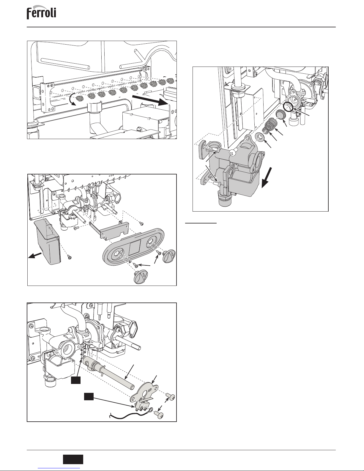
fig. 7 Remplacer les gicleurs du brûleur principal en montant les gicleurs indi-
qués sur le tableau des données techniques cap. 5, en fonction du type de
gaz utilisé
fig. 7
fig. 8 Dégager les boutons de réglage.
Desserrer les deux vis (1) et enlever le bandeau.
Desserrer la vis (2) et enlever l'unité électronique.
Desserrer les vis (3 et 4) et enlever l'étrier de support du bandeau.
fig. 8
fig. 9 Desserrer les deux vis (1), dégager la plaquette (2) et remplacer le régu-
lateur de puissance (3).
fig. 9
fig. 10 Desserrer les deux vis (1) de fixation de la vanne à gaz et remplacer le
cône de modulation (6).
Réassembler tous les composants puis s'assurer que le joint (7) est instal-
lé correctement et que le fil de masse (4 de fig. 9) est fixé correctement.
Appliquer la plaquette adhésive contenue dans le kit de transformation
près de la plaquette des données techniques afin de signaler la transformation effectuée.
fig. 10
4.2 Mise en service
Opérations à effectuer avant d'allumer le chauffe-eau
• Vérifier l'étanchéité de l'installation du gaz.
• Remplir le circuit hydraulique et purger l'air contenu dans le chauffe-eau et dans le
circuit.
• S'assurer qu'il n'y a aucune fuite d'eau le long du circuit et sur l'appareil.
• S'assurer que la pression du gaz est correcte.
• S'assurer qu'il n'y a aucun liquide ou matériau inflammable à proximité du chauffe-eau.
Vérifications en cours de fonctionnement
• Mettre l’appareil en marche
• S'assurer de l'étanchéité des circuits combustible et eau.
• Contrôler l'efficacité de la cheminée et des conduits de fumée pendant que le chauffe-eau est en marche
• Vérifier si le chauffe-eau s'allume correctement en effectuant plusieurs essais d'allumage et d'extinction.
• S'assurer que la consommation de combustible indiquée par le compteur correspond à celle qui est indiquée dans le tableau des caractéristiques techniques
cap. 5.
2
1
3
4
2
1
4
3
A
B
3
5
4
6
7
1
Page 16
SKY C B
16
FR
cod. 3541C702 - Rev. 01 - 06/2014
4.3 Entretien
Démontage de l'habillage
Pour retirer l'habillage du chauffe-eau :
1. Dévisser les deux vis A (voir fig. 11).
2. Tourner l'habillage.
3. Soulever et retirer l'habillage.
B
Avant d'effectuer une quelconque opération à l'intérieur du chauffe-eau, fermer
le robinet du gaz en amont.
fig. 11 - Démontage de l'habillage
Remplacement des batteries
Pour remplacer les batteries, procéder selon les explications fig. 12.
fig. 12 - Remplacement des batteries
Contrôle périodique
Pour un fonctionnement correct durable de l'appareil, il est nécessaire de faire effectuer
par un professionnel qualifié un contrôle annuel qui prévoit les opérations suivantes :
• Les dispositifs de commande et de sécurité doivent fonctionner correctement.
• Le circuit d'évacuation des fumées doit être parfaitement efficace.
• Les conduits de fumée et cheminées doivent être libres de tout obstacle et ne présenter aucune fuite
• Le brûleur et l'échangeur doivent être propres et détartrés. Pour le nettoyage, ne
pas utiliser de produits chimiques ni de brosses en acier.
• Les électrodes ne doivent présenter aucune incrustation et doivent être positionnées correctement.
fig. 13 - Mise en place des électrodes
• Les installations de gaz et d'eau doivent être parfaitement étanches.
• La charge et la pression de gaz doivent correspondre aux valeurs indiquées dans
les tableaux correspondants.
5. CARACTÉRISTIQUES ET DONNÉES TECHNIQUES
Tableau 3 - Légende figures cap. 5
5.1 Vue générale et composants principaux
fig. 14 1.4 Vue générale
A
A
1
3
2
3
±
0,5
= =
7 Arrivée gaz 78 Antirefouleur
8 Sortie eau chaude sanitaire 82 Électrode de détection
9 Entrée eau chaude sanitaire 83 Module électronique de commande
19 Chambre de combustion 126 Thermostat fumées à contact
20 Groupe brûleurs 188 Électrode d'allumage
27 Échangeur en cuivre 358 Thermostat solaire entrée sanitaire
42 Capteur température sanitaire 359 Débitmètre
44 Vanne à gaz 372 Batteries
49 Thermostat de sécurité
78
27
188
82
20
49
126
879
44
42
19
358
Page 17
SKY C B
17
FR
cod. 3541C702 - Rev. 01 - 06/2014
5.2 Schémas hydrauliques
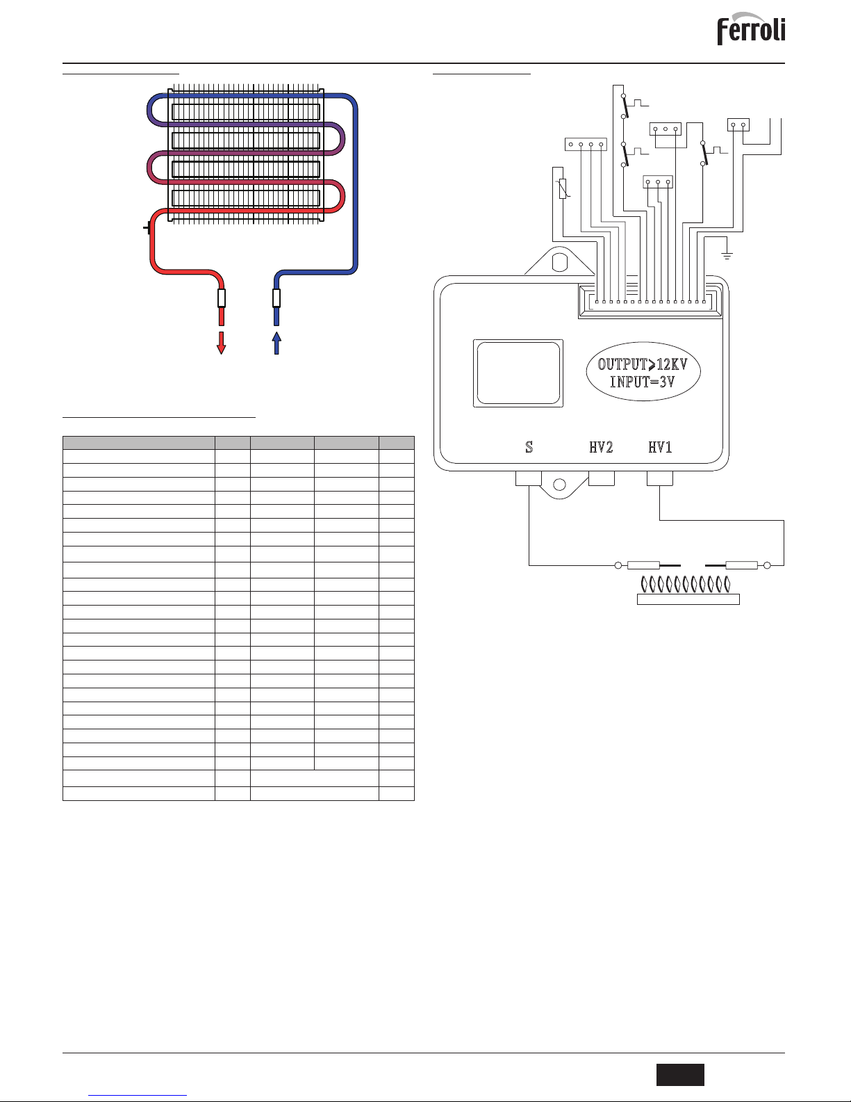
fig. 15 - Circuit hydraulique
5.3 Tableau des caractéristiques techniques
5.4 Schéma électrique
fig. 16
Donnée Unité SKY C 11 B SKY C 14 B
Puissance thermique maxi kW 21.7 26.9 (Q)
Puissance thermique mini kW 8.3 10.3 (Q)
Puissance thermique maxi kW 19.2 23.9
Puissance thermique mini kW 7.1 8.8
Rendement Pmax % 88.5 88.7
Gicleurs brûleur G20 nbre x Ø 10 x 1.25 12 x 1.25
Pression d'alimentation gaz G20 mbar 20.0 20.0
Débit gaz à puissance maxi G20
m
3
/h
02:30 2.85
Débit gaz à puissance mini G20
m
3
/h
0.88 01:10
Gicleurs brûleur G30 nbre x Ø 10 x 0.77 12 x 0.77
Pression d'alimentation gaz G30 mbar 29.0 29.0
Débit gaz maxi G30 kg/h 1.70 2.11
Débit gaz mini G30 kg/h 0.65 0.80
Gicleurs brûleur G31 nbre x Ø 10 x 0.77 12 x 0.77
Pression d'alimentation gaz G31 mbar 37 37
Débit gaz à puissance maxi G31 kg/h 1.70 2.11
Débit gaz à puissance mini G31 kg/h 0.65 0.80
Pression maxi de service bar 10 10 (PMS)
Pression mini de service bar 00:20 00:20
Débit d'eau sanitaire à Dt 25 °C l/min 11.0 14.0
Débit d'eau sanitaire à Dt 50°C l/min 5.5 6.8 (D)
Indice de protection IP X5D X5D
Poids à vide kg 11 12
Type d'appareil
B
11B S
PIN CE 0461CL0984
89
358
49
42
82 188
Marking
78910111213141516654321
4321
126
49
321
DISPLAY
44
359
321
358
12
_
+
372
ON/OFF
42
83
Page 18
SKY C B
18
TR
cod. 3541C702 - Rev. 01 - 06/2014
TR
1. GENEL UYARøLAR
• Bu talimat kitapçÕ÷Õnda yer alan uyarÕlarÕ dikkatlice okuyunuz ve bunlara uyunuz.
• CihazÕn kurulumu yapÕldÕktan sonra, çalÕúmasÕ konusunda kullanÕcÕyÕ bilgilendiriniz ve
ürünün tamamlayÕcÕ ve önemli bir parçasÕ olan ve ileride baúvurulmak üzere itina ile saklanmasÕ gereken bu kÕlavuzu kendisine teslim ediniz.
• Kurulum ve bakÕm iúlemleri yürürlükteki standartlara ve üreticinin talimatlarÕna uygun úekilde gerçekleútirilmeli ve mesleki açÕdan kalifiye bir personel tarafÕndan yapÕlmalÕdÕr.
CihazÕn mühürlü ayar parçalarÕna müdahale edilmesi yasaktÕr.
• HatalÕ kurulum veya yetersiz bakÕm insanlara, hayvanlara ya da nesnelere zarar verebilir.
Üretici firma, kurulum ve kullanÕmdaki hatalardan ve talimatlara uyulmamasÕndan kaynaklanan hasarlardan hiçbir úekilde sorumlu tutulamaz.
• Herhangi bir temizlik veya bakÕm iúlemi gerçekleútirmeden önce, özel açma-kapama
aygÕtlarÕnÕ kullanarak gazÕ kapatÕn
Õz.
•CihazÕn arÕzalanmasÕ ve/veya düzgün çalÕúmamasÕ durumunda, cihazÕ devre dÕúÕ bÕrakÕnÕz,
tamir etmekten veya direk müdahalede bulunmaktan kaçÕnÕnÕz. YalnÕzca mesleki olarak kalifiye personel ile temasa geçiniz. Ürünlerin herhangi bir onarÕm-de÷iútirme iúlemi, sadece
mesleki olarak kalifiye personel tarafÕndan ve sadece orijinal parçalar kullanÕlarak yerine getirilmelidir. YukarÕda belirtilen koúullara uyulmamasÕ, cihazÕn emniyetini tehlikeye atabilir.
• Bu cihaz yalnÕzca özel olarak tasarlanmÕú oldu÷u amaçlar için kullanÕlmalÕdÕr. Bunun
dÕúÕndaki herhangi bir kullanÕm, yanlÕú ve bu nedenle tehlikeli olarak de÷erlendirilir.
• Ambalaj parçalarÕ potansiyel tehlike kayna÷Õ oldu÷undan, çocuklarÕn eriúebilece÷i yerlerde
bÕrakÕlmamalÕdÕr.
• Bu cihaz fiziksel, duyusal veya zihinsel kapasiteleri yetersiz kiúiler (çocuklar dahil) veya yeterli
bilgi veya deneyime sahip olmayan kiúiler tarafÕndan kullanÕlmak üzere tasarlanmamÕútÕr. Bu
kiúiler cihazÕ ancak kendi güvenliklerinden sorumlu bir kiúinin gözetiminden veya cihazÕn kullanÕmÕyla ilgili yönlendirmelerinden faydalanabildikleri takdirde kullanabilirler.
•AygÕtÕn ve buna ait aksesuarlarÕn imhasÕ düzgün úekilde, yürürlükteki standartlara uygun
olarak gerçekleútirilmelidir.
•Bu kÕlavuzda yer alan resimler ürünün sadeleútirilmiú görüntüsünü temsil etmektedir. Bu
temsili görüntüler ile size temin edilen ürün arasÕnda küçük ve önemsiz farklar olabilir.
2. KULLANMA TALIMATLARø
2.1 TanÕtÕm
SKY C B do÷al gaz veya propan gazÕ ile çalÕúan ve elektronik ateúlemeli atmosferik
brülör ile donatÕlmÕú, akü ile beslenen yüksek verimli sÕcak sÕhhi su üretimi amaçlÕ, dahili
mekana kurulan bir ani su ÕsÕtÕcÕsÕdÕr.
2.2 Kumanda paneli
Panel
úek. 1 - Kontrol paneli
Panel açÕklamalarÕ úek. 1
1 SÕcak sÕhhi sÕcaklÕ÷ÕnÕ görüntüleme
2 Akü seviyesi iúareti
3 Brülör gücünü ayarlama/kapatma
4 SÕcaklÕ÷Õ ayarlama
5 Alev sembolü
ÇalÕúma anÕndaki gösterim
Çizelge 1 - Gösterge sembollerinin anlamlarÕ
SÕcak sÕhhi su alÕnmasÕ ile oluúan sÕhhi su talebi esnasÕnda gösterge aktüel sÕcak sÕhhi
su çÕkÕú sÕcaklÕ÷ÕnÕ görüntüler.
2.3 Açma ve kapatma
ølk kontroller ve iúlemler
1. SÕcak su musluklarÕnÕn kapalÕ oldu÷undan emin olunuz.
2. Su ÕsÕtÕcÕsÕna gaz beslemesi sa÷layan muslu÷u açÕnÕz (cihazÕn gaz ba÷lantÕsÕ üzerinde yer alÕr);
3. 1,5 V'luk akülerin yuvalarÕna do÷ru polarite (+ ve -) ile yerleútirilmiú oldu÷unu kontrol
ediniz.
BunlarÕn de÷iútirilmesi için, bkz. *** 'Aküleri de÷iútirme' on page 21 ***.
4. AyrÕca, su ÕsÕtÕcÕsÕnÕn çalÕúmasÕ için akülerin yeterli úarja sahip oldu÷undan emin
olunuz.
Ateúleme
Dü÷meyi çevirerek, istenilen su Õs
Õtma seviyesi konumuna getiriniz.
úek. 2 - Yakma
Cihaz, her sÕcak sÕhhi su alÕmÕnda otomatik olarak çalÕúmak üzere derhal hazÕr olacaktÕr.
Söndürme
Brülör, sÕcak sÕhhi su alÕmÕ durduruldu÷unda otomatik olarak söner.
Yeni bir yakma fazÕ gerçekleútirmek için özel bir iúlem yapÕlmasÕ gerekmemektedir.
CihazÕ tamamen kapamak için dü÷meyi [ ] konumuna getiriniz .
úek. 3 - CihazÕ devre dÕúÕ bÕrakma
Uzun süreli kapatma durumunda cihazÕn giriú kÕsmÕnda yer alan gaz muslu÷unu
kapatÕnÕz.
B
KÕú döneminde uzun süreli olarak kapalÕ kalmasÕ durumunda donmadan kaynaklanan hasarlarÕ önlemek için, su ÕsÕtÕcÕsÕndaki suyun tümünün tahliye edilmesi önerilmektedir.
2.4 Ayarlamalar
Brülör gücünü manuel ayarlama
Güç ayarlama dü÷mesi kullanÕlarak (ref. 3 - úek. 1) istenilen su ÕsÕtma seviyesine göre
su ÕsÕtÕcÕsÕ gücünün minimum veya maksimum ve ara konumlarÕ seçilebilir. Dü÷me saatin
tersi yöne çevrildi÷inde, cihaz suyu maksimum güçte ÕsÕtÕr. SÕcaklÕ÷Õn çok yüksek olmasÕ
halinde (örne÷in yazÕn) veya düúük kapasitede ÕlÕk su gerekti÷inde dü÷meyi saat yönünde çeviriniz. Bu úekilde güç (ve gaz tüketimi) azalacaktÕr. ( ) konumunda cihaz devre
dÕúÕdÕr.
SÕcaklÕ÷Õ ayarlama
SÕcaklÕk seçme dü÷mesi kullanÕlarak su sÕcaklÕ÷Õ kolaylÕkla ayarlanabilir: sÕcaklÕ÷Õ
arttÕ
rmak için sa÷a, azaltmak için sola do÷ru çeviriniz.
úek. 4 - SÕcaklÕk ayarÕ
ArÕzalar
Belirtilen ayarlama iúlemleri yapÕldÕktan sonra, su ÕsÕtÕcÕsÕ artÕk tamamen otomatik modda
çalÕúmaya hazÕr durumda olacaktÕr. Bir sÕcak su muslu÷unun açÕlmasÕyla, ateúleme elektrotu üzerinde brülörün yanÕúÕnÕ úartlandÕran aralÕklÕ bir boúalma meydana gelir.
Elektronik modellerin tümü, alev düzgünlü÷ünün kontrolü için brülörün içerisine takÕlmÕú
bir iyonizasyon elektrotu içermektedir. ArÕza veya gaz beslemesinin kesilmesi neticesinde brülörün sönmesi halinde, sÕcak su muslu÷u kapatÕlmalÕdÕr.
ArdÕndan, gazÕn su ÕsÕtÕ
c
ÕsÕna ulaúmasÕnÕ engelleyen sorun veya öge (örne÷in gaz mu-
slu÷unun kazara kapatÕlmasÕ, gaz tüpünün boúalmasÕ, vs) ortadan kaldÕrÕlmalÕdÕr.
Su ÕsÕtÕcÕsÕnÕn kilidi, sÕcak su muslu÷unun kapatÕlÕp açÕlmasÕ suretiyle devre dÕúÕ bÕrakÕlÕr.
Sebep ortadan kaldÕrÕlÕp, sÕcak su muslu÷u açÕldÕ÷Õnda hala sÕcak su alÕnamÕyorsa iúlemi
tekrarlayÕnÕz. ArÕzanÕn devam etmesi halinde, Teknik Destek Servisine baú
vurunuz.
Yan Õp sönen sembol: brülör açÕk.
Brülör kapalÕ ise bu sembol görüntülenmez.
Su ÕsÕtÕcÕsÕ çÕkÕúÕnda su sÕcaklÕ÷Õ..
Sembol sabit. Akü boúalmak üzere. De÷iútirilmesi önerilir.
Yan Õp sönen sembol. Akü boú ve de÷iútirilmesi gerekiyor..
12345
Page 19

SKY C B
19
TR
cod. 3541C702 - Rev. 01 - 06/2014
Çizelge 2 - ArÕza tablosu
3. KURULUM
3.1 Genel talimatlar
SU ISITICISI, BU TEKNøK KULLANIM KøTAPÇIöINDA BELøRTøLMEKTE OLAN BÜTÜN
TALøMATLARA, YÜRÜRLÜKTE OLAN øLGøLø ULUSAL STANDARTLARA VE YEREL
TÜZÜKLERE UYGUN BøR ùEKøLDE, øùÇøLøK KURALLARINA TAM OLARAK UYGUNLUK øÇøNDE VE SADECE KALøFøYE BøR PERSONEL TARAFINDAN MONTE
EDøLMELøDøR.
3.2 Kurulum yeri
Bu cihaz, bir "açÕk oda" tiplidir ve sadece sürekli havalandÕrÕlan odalarda monte edilip
çalÕútÕrÕlabilir. Su ÕsÕtÕcÕsÕna yanma havasÕ akÕúÕnÕn yetersiz gelmesi durumunda, cihazÕn
normal çalÕúmasÕ ve duman tahliyesi bundan etkilenecektir AyrÕca, bu tür úartlarda ortaya
çÕkan yanma ürünleri, ev ortamÕna yayÕlmalarÕ halinde sa÷lÕ÷a aúÕrÕ derecede zarar verir.
CihazÕ kurmak istedi÷iniz yerin Yürürlükteki Standartlarda öngörülen tüm koúullara sahip
oldu÷undan emin olunuz.
Kurulum yeri toz, yanÕcÕ malzeme ya da nesneler veya korozif gazlar içermemelidir.
SÕ ÕsÕtÕcÕsÕnÕ mümkün oldu÷unca sÕcak su musluklarÕ
nÕn yakÕnÕna, lavabonun yakÕnÕna
konumlandÕrÕnÕz fakat ASLA oca÷Õn üstüne konumlandÕrmayÕnÕz. AyrÕca, duman borusuna veya baca gazÕ tahliye borusunun baúlangÕç noktasÕna mümkün oldu÷unca yakÕn
yerde olmalÕdÕr.
A
E÷er cihaz bir mobilya içerisine veya yakÕnÕna monte edilecekse, muhafazanÕn
çÕkartÕlabilmesi için ve normal bakÕm iúlemleri için bir açÕklÕk bÕrakÕlmalÕdÕr.
3.3 Su ba÷lantÕlarÕ
UyarÕlar
B
Ba÷lantÕ iúlemini yapmadan önce, cihazÕn mevcut yakÕt tipi ile çalÕúmak üzere
ayarlanmÕú oldu÷undan emin olunuz ve cihazÕn bütün borularÕnÕ dikkatlice temizleyiniz.
Ba÷lantÕlarÕ, ilgili ba÷lantÕ noktalarÕna kapaktaki çizime ve cihaz üzerinde belirtilen sembollere uygun úekilde yapÕnÕz.
Sistem suyunun özellikleri
Suyun 25° Fr sertlik derecesinden (1°F = 10ppm CaCO
3
) daha sert olmasÕ halinde, su
ÕsÕtÕcÕsÕnda olasÕ tortularÕ önlemek için uygun úekilde arÕtÕlmÕú su kullanÕmÕnÕ öneririz.
3.4 Gaz ba÷lantÕsÕ
Gaz, ilgili bulunan konnektöre (bkz. kapaktaki úekil ) yürürlükteki standartlara uygun
úekilde, sert metal boru ile veya devamlÕ esnek s/çelik duvar boru tesisatÕ ile ve de sistem
ile su ÕsÕtÕcÕsÕ arasÕna bir gaz muslu÷u yerleútirilerek ba÷lanmalÕdÕr. Tüm gaz
ba÷lantÕlarÕnÕn sÕkÕ bir úekilde ba÷landÕ÷Õndan emin olunuz
3.5 Duman kanalÕ
Duman borusuna takÕlan rakor borusu, geri akÕú önleme cihazÕnÕn ba÷lantÕ borusuna
göre daha küçük bir çapa sahip olmalÕdÕr. Geri akÕú önleme cihazÕndan itibaren,
uzunlu÷u yarÕm metreden az olmayan bir dikey kesite sahip olmalÕdÕr. Duman borularÕnÕn
ve bunlarÕn rakor borularÕnÕn ebadÕ ve montajÕ ile ilgili olarak, yürürlükteki standartlara
riayet edilmelidir.
B
Su ÕsÕtÕcÕsÕ, duman borusunun iyi çekmemesi veya tÕkanmasÕ halinde cihazÕn
çalÕúmasÕnÕ engelleyen bir emniyet cihazÕ (duman termostatÕ) ile donatÕlmÕútÕr.
Bu cihaz asla kurcalanmamalÕ veya devre dÕúÕ bÕrakÕlmamalÕdÕr.
4. SERVIS VE BAKøM
AçÕklanan tüm ayarlama, servise alma ve periyodik kontrol iúlemleri, sadece Kalifiye bir
Personel (yürürlükteki standartlarÕn öngördü÷ü profesyonel teknik gereklilikler hakkÕnda
bilgi sahibi olan bir personel) tarafÕndan gerçekleútirilmelidir
FERROLI cihazÕn yetkisiz kiúiler tarafÕndan kurcalanmasÕndan kaynaklanan, insanlara
ve/veya eúyalara gelebilecek hasarlarla ilgili hiçbir sorumluluk kabul etmez.
4.1 Regülasyonlar
Gaz beslemesini dönüútürme
B
Fabrikada ayarlanmÕú oldu÷undan farklÕ bir gaza göre dönüútürme iúlemi
yetkili bir teknisyen tarafÕndan, orijinal parçalar kullanÕlarak ve cihazÕn kurulaca÷Õ ülkede yürürlükte olan standartlara uygun úekilde gerçekleútirilmelidir.
Bu cihaz hem Metan gazÕ hem de LPG beslemesi ile çalÕúabilmektedir ve ayrÕca bu iki
gazdan birisi ile çalÕúmak üzere gerekli ayarlarÕ, ambalajÕnda ve bilgi etiketinde açÕkça
belirtildi÷i gibi fabrikada yapÕlmaktadÕr. CihazÕn, ayarlanmÕú oldu÷u gaz türünden farklÕ
bir gaz ile kullanÕlmasÕ gerekti÷inde, bir gaz dönüútürme kitinin kullanÕlmasÕ ve aúa÷Õda
açÕklanan iúlemlerin yapÕlmasÕ gerekmektedir:
úek. 5 ElektrotlarÕn kablo ba÷lantÕlarÕnÕ
kesiniz.
úek. 5
úek. 6 Brülör kapa÷ÕnÕ sabitleyen dört vidayÕ söküp, kasayÕ çÕkarÕnÕz.
úek. 6
Brülör ateúleme yapmÕyor
Gaz yok
Kombiye gelen gaz akÕúÕnÕn
düzenli oldu÷undan ve havanÕn
borulardan tahliye edildi÷inden
emin olun
Elektrot tespit/ateúleme hatasÕ
Elektrodun kablolarÕnÕ kontrol
edin, do÷ru konumlanmÕú
oldu÷undan ve herhangi bir tortu
içermedi÷inden emin olun
Gaz valfÕ arÕzalÕ
Gaz valfÕnÕ kontrol edin ve/veya
de÷iútirin
Brülör kapalÕ iken alev
var sinyali
Elektrot arÕzasÕ
øyonizasyon elektrodunun
kablolarÕnÕ kontrol edin
Kart arÕzasÕ
KartÕ kontrol edin ve/veya
de÷iútirin
AúÕrÕ-sÕcaklÕk korumasÕnÕn
devreye girmesi
IsÕtma sensörü hasarlÕ veya do÷ru
konumlandÕrÕlmamÕú
IsÕtma sensörünün do÷ru
konumlandÕ÷Õndan ve düzgün
çalÕútÕ÷Õndan emin olunuz
ve/veya de÷iútiriniz
Duman termostatÕ müdahalesi
(duman termostatÕ devreye
girdikten sonra, cihazÕn
çalÕúmasÕ termostat so÷uk
haldeyken musluk kapatÕlÕp
tekrar açÕlarak devam
ettirilebilir)
Duman termostatÕnÕn konta÷Õ
açÕktÕr
Te rm o st a t Õ kontrol edin
Kablolarda kopukluk var Kablo tesisatÕnÕ kontrol edin
Baca yanlÕú boyutlandÕrÕlmÕú veya
tÕkalÕ
Duman kanalÕ
nÕ/borusunu
kontrol ediniz
Gösterge KAPALI
Solar termostatÕ açÕk
Solar termostatÕnÕ kontrol edin
veya de÷iútirin
Pil boúalmÕú Pili de÷iútirin
KablolarÕn ba÷lantÕsÕ kopmuú KablolarÕ kontrol edin/de÷iútirin
Mikro (ref.
A
- -úek. 9) anahtarlama
yapmÕyor
Mikroyu kontrol edin/de÷iútirin
Komut mikrosu (ref.
B
- úek. 9)
anahtarlama yapmÕyor
Mikroyu kontrol edin/de÷iútirin
Sensör ba÷lantÕsÕ kopmuú
Ba÷lantÕyÕ kontrol edin veya
sensörü de÷iútirin
Page 20
SKY C B
20
TR
cod. 3541C702 - Rev. 01 - 06/2014
úek. 7 Ana brülör alev uçlarÕnÕ de÷iútiriniz ve kullanÕlmakta olan gazÕn tipine göre
cap. 5 teknik veri tablosunda belirtildi÷i úekilde uçlarÕ takÕnÕz
úek. 7
úek. 8 Ayar dü÷mesini çÕkarÕnÕz.
øki vidayÕ (1) söküp, ÕzgarayÕ çÕkarÕnÕz.
VidayÕ (2) sökünüz ve elektronik santrali çÕkarÕnÕz.
VidalarÕ (3 ve 4) sökünüz ve Õzgara destek braketini çÕkarÕnÕz.
úek. 8
úek. 9
øki vidayÕ (1) sökünüz, levhayÕ (2) çÕkarÕnÕz ve güç ayarlayÕcÕsÕnÕ (3) de÷iútiriniz.
úek. 9
úek. 10 Gaz valfÕnÕ sabitleyen iki vidayÕ (1) sökünüz ve modülasyon konisini (6)
de÷iútiriniz.
ContanÕn (7) do÷ru bir úekilde konumlandÕrÕlmasÕna ve topraklama kablo-
sunun (4 - úek. 9) do÷ru bir úekilde takÕlmasÕna dikkat ederek tüm parçalarÕ
geri takÕnÕz.
Dönüútürme yapÕldÕ÷ÕnÕ göstermek için, dönüúüm kitindeki etiketi teknik
veriler etiketinin yanÕna yapÕútÕrÕn.
úek. 10
4.2 Servise alma
Su ÕsÕtÕcÕsÕnÕ yakmadan önce
• Gaz sisteminin sÕzdÕrmazlÕ÷ÕnÕ kontrol ediniz.
• Su sistemini doldurunuz ve su ÕsÕtÕcÕsÕ ile sistem içerisindeki havanÕn tamamen
boúaltÕlmasÕnÕ sa÷layÕnÕz.
• Sistemde veya cihaz içerisinde su kaça÷Õ olmadÕ÷Õndan emin olunuz.
•Gaz basÕncÕ de÷erinin istenilen de÷er oldu÷undan emin olunuz:
•Su ÕsÕtÕcÕsÕnÕn yakÕnlarÕnda alev alÕcÕ özellikte sÕvÕlar veya malzemeler olmadÕ÷Õndan
emin olunuz.
øúletim anÕndaki kontroller
• CihazÕ çalÕútÕrÕnÕz.
•YakÕt devresinin ve su sistemlerinin sÕzdÕrmazlÕ÷ÕnÕ kontrol ediniz.
•Su ÕsÕtÕcÕsÕnÕn çalÕúmasÕ esnasÕnda, bacanÕn ve duman kanalÕnÕn etkinli÷ini kontrol
ediniz.
•Çeúitli yakma ve söndürme testleri yapmak suretiyle su ÕsÕtÕcÕsÕnÕn iyi yandÕ÷Õndan
emin olunuz.
• Sayaç üzerinde belirtilen yakÕt sarfiyatÕnÕn cap. 5 bölümündeki teknik veriler tablosunda belirtilen de÷ere karúÕlÕk geldi÷inden emin olunuz.
2
1
3
4
2
1
4
3
A
B
3
5
4
6
7
1
Page 21
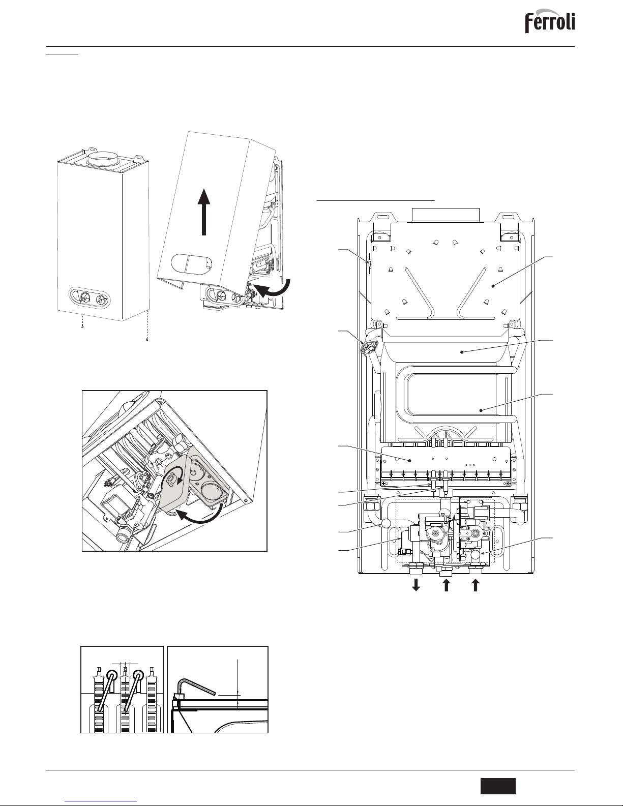
SKY C B
21
TR
cod. 3541C702 - Rev. 01 - 06/2014
4.3 BakÕm
Muhafaza kasasÕnÕ açma
Su ÕsÕtÕcÕsÕnÕn muhafaza kasasÕnÕ açmak için:
1. øki vidayÕ A sökünüz (bkz. úek. 11)
2. KasayÕ döndürünüz.
3. KasayÕ yukarÕ kaldÕrÕp çÕkarÕnÕz.
B
Su ÕsÕtÕcÕnÕn iç kÕsmÕnda herhangi bir iúlem yapmadan önce sistem giriúindeki
gaz muslu÷unu kapatÕnÕz
úek. 11 - Muhafaza kasasÕnÕ açma
Aküleri de÷iútirme
Aküleri de÷iútirmek için úekilde açÕklanan iúlemleri yapÕnÕz, bkz.úek. 12.
úek. 12 - Aküleri de÷iútirme
Periyodik kontrol
CihazÕn zaman içinde düzgün çalÕúmaya devam etmesini sa÷lamak için, kalifiye bir personele aúa÷Õdaki kontrol iúlemlerini öngören bir yÕllÕk kontrol yaptÕrmanÕz gerekmektedir:
• Kumanda ve emniyet cihazlarÕ düzgün úekilde çalÕúmalÕdÕr.
• Duman tahliye devresi tam verimlilikte olmalÕdÕ
r.
• Duman kanallarÕnda ve terminalinde herhangi bir tÕkanÕklÕk ve kaçak olmamalÕdÕr
• Brülör ve eúanjör temiz ve tortusuz olmalÕdÕr. Temizlik iúlemlerinde kimyasal ürünler
veya çelik fÕrçalar kullanmayÕnÕz.
• Elektrotlar kireçlenmemiú ve düzgün konumlanmÕú olmalÕdÕr.
úek. 13 - ElektrotlarÕn konumlandÕrmasÕ
• Gaz ve su sistemleri hava geçirmez durumda olmalÕdÕr
• Gaz kapasitesi ve basÕncÕ ilgili tablolarda belirtilen de÷erlere karúÕlÕk gelmelidir.
5. TEKNIK ÖZELLIKLER VE VERILER
Çizelge 3 - ùekil açÕklamalarÕ cap. 5
5.1 Genel görünüm ve ana bileúenler
úek. 14 - Genel görünüm
A
A
1
3
2
3
±
0,5
= =
7 Gaz giriúi 78 Geri-akÕú önleme cihazÕ
8 SÕhhi su çÕkÕúÕ 82 Tespit elektrodu
9 SÕhhi su giriúi 83 Elektronik kumanda santrali
19 Yanma odasÕ 126 KontaklÕ duman termostatÕ
20 Brülör grubu 188 Ateúleme elektrodu
27 BakÕr eúanjör 358 Solar termostat sÕhhi su giriúi
42 Musluk suyu sÕcaklÕk sensörü 359 AkÕú sivici
44 Gaz valfÕ 372 Akü
49 Emniyet termostatÕ
78
27
188
82
20
49
126
879
44
42
19
358
Page 22
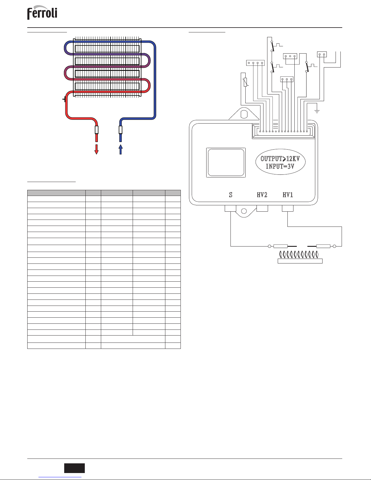
SKY C B
22
TR
cod. 3541C702 - Rev. 01 - 06/2014
5.2 Hidrolik úemalarÕ
úek. 15 - Hidrolik devre
5.3 Teknik veriler tablosu
5.4 Elektrik úemasÕ
úek. 16
Veri Birim SKY C 11 B SKY C 14 B
Maks. termik kapasite kW 21.7 26.9 (Q)
Min. termik kapasite kW 8.3 10.3 (Q)
Maks.Termik Güç kW 19.2 23.9
Min. Termik Güç kW 7.1 8.8
Verim Pmax % 88.5 88.7
Brülör uçlarÕ G20 n° x Ø 10 x 1.25 12 x 1.25
Besleme gazÕ basÕncÕ G20 mbar 20.0 20.0
Maks. gaz kapasitesi G20
m
3
/sa
2.30 2.85
Min. gaz kapasitesi G20
m
3
/sa
0.88 1.10
Brülör uçlarÕ G30 n° x Ø 10 x 0.77 12 x 0.77
Gaz besleme basÕncÕ G30 mbar 29.0 29.0
Maks. gaz kapasitesi G30 kg/sa 1.70 2.11
Min. gaz kapasitesi G30 kg/sa 0.65 0.80
Brülör uçlarÕ G31 n° x Ø 10 x 0.77 12 x 0.77
Gaz besleme basÕncÕ G31 mbar 37 37
Maks. gaz kapasitesi G31 kg/sa 1.70 2.11
Min. gaz kapasitesi G31 kg/sa 0.65 0.80
Maks. çalÕúma basÕncÕ bar 10 10 (PMS)
Min. çalÕúma basÕncÕ bar 0.20 0.20
SÕhhi su çÕkÕúÕ
'
t 25°C l/dak 11.0 14.0
SÕhhi su çÕkÕúÕ
'
t 50°C l/dak 5.5 6.8 (D)
Koruma derecesi IP X5D X5D
Boú a÷ÕrlÕkkg1112
Cihaz tipi
B
11BS
PIN CE 0461CL0984
89
358
49
42
82 188
Marking
78910111213141516654321
4321
126
49
321
DISPLAY
44
359
321
358
12
_
+
372
ON/OFF
42
83
Page 23
Dichiarazione di conformità
Il costruttore: FERROLI S.p.A.
Indirizzo: Via Ritonda 78/a 37047 San Bonifacio VR
dichiara che questo apparecchio è conforme alle seguenti direttive CEE:
• Direttiva Apparecchi a Gas 2009/142
• Direttiva Bassa Tensione 2006/95
• Direttiva Compatibilità Elettromagnetica 2004/108
Presidente e Legale rappresentante
Cav. del Lavoro
Dante Ferroli
IT
Uygunluk beyani
ømalatçi: FERROLI S.p.A.
Adres: Via Ritonda 78/a 37047 San Bonifacio VR
bu cihazin; asagida yer alan AET(EEC) yönergelerine uygunluk içinde oldugunu beyan etmektedir:
• 2009/142 Gazla çalistirilan üniteler için Yönetmelik
• Yönerge 2006/95, Düsük Voltaj
• 2004/108 Elektromanyetik Uygunluk Yönetm
eligi
Baskan ve yasal temsilci
øú. Dep.
Dante Ferroli
TR
Declaration of conformity
Manufacturer: FERROLI S.p.A.
Address: Via Ritonda 78/a 37047 San Bonifacio VR Italy
declares that this unit complies with the following EU directives:
• Gas Appliance Directive 2009/142
• Low Voltage Directive 2006/95
•E
lectromagnetic Compatibility Directive 2004/108
President and Legal Representative
Cav. del Lavoro
Dante Ferroli
EN
Déclaration de conformité
Le constructeur : FERROLI S.p.A.
Adresse: Via Ritonda 78/a 37047 San Bonifacio VR
déclare que cet appareil est conforme aux directives CEE ci-dessous:
• Directives appareils à gaz 2009/142
• Directive basse tension 2006/95
• Directive Compatibilité Electromagnétique 2004/108
Président et fondé de pouvoirs
Cav. du travail
Dante Ferroli
FR
Page 24

FERROLI S.p.A.
Via Ritonda 78/a
37047 San Bonifacio - Verona - ITALY
www.ferroli.it
 Loading...