


i migliori gradi centigradi
MONITORING SYSTEM
FOR SERIES:
• RHV R134a
• RHV R407C BTZ
• RVW
• RLA
• RHA
INSTRUCTION MANUAL

2
The manufacturer declines all responsibility for any inaccuracies in this manual due to printing or typing errors.
The manufacturer reserves the right to make changes and improvements to products in the catalog at any time and without notice.

3
TABLE OF CONTENTS
MONITORING SYSTEM - User interface . . . . . . . . . . . . . . . . . . . . . . . . . . . . . . . . . . . . . . . . . . . . . . . . . . . . . . . . . . . . . . .5
CONTROL PANEL . . . . . . . . . . . . . . . . . . . . . . . . . . . . . . . . . . . . . . . . . . . . . . . . . . . . . . . . . . . . . . . . . . . . . . . . . . . .5
FUNCTION BUTTONS “F1”, “F2”, “F3”, “F4” AND “ON/OFF” . . . . . . . . . . . . . . . . . . . . . . . . . . . . . . . . . . . . . . . . . . .5
JOYSTICK BUTTON: “MENU”
. . . . . . . . . . . . . . . . . . . . . . . . . . . . . . . . . . . . . . . . . . . . . . . . . . . . . . . . . . . . . . . . . . .6
LED STATUS . . . . . . . . . . . . . . . . . . . . . . . . . . . . . . . . . . . . . . . . . . . . . . . . . . . . . . . . . . . . . . . . . . . . . . . . . . . . . . . .6
MONITORING SYSTEM - User menù . . . . . . . . . . . . . . . . . . . . . . . . . . . . . . . . . . . . . . . . . . . . . . . . . . . . . . . . . . . . . . . . . .7
COOLING MODE IR . . . . . . . . . . . . . . . . . . . . . . . . . . . . . . . . . . . . . . . . . . . . . . . . . . . . . . . . . . . . . . . . . . . . . . . . . . .7
HEATING MODE IP (reversible refrigerant side) . . . . . . . . . . . . . . . . . . . . . . . . . . . . . . . . . . . . . . . . . . . . . . . . . . . . .8
HEATING MODE IW (reversible water side) . . . . . . . . . . . . . . . . . . . . . . . . . . . . . . . . . . . . . . . . . . . . . . . . . . . . . . . .9
HEAT RECOVERY . . . . . . . . . . . . . . . . . . . . . . . . . . . . . . . . . . . . . . . . . . . . . . . . . . . . . . . . . . . . . . . . . . . . . . . . . . . .10
MONITORING SYSTEM - User setting . . . . . . . . . . . . . . . . . . . . . . . . . . . . . . . . . . . . . . . . . . . . . . . . . . . . . . . . . . . . . . . .11
CONTROL PANEL UNIT ON/OFF . . . . . . . . . . . . . . . . . . . . . . . . . . . . . . . . . . . . . . . . . . . . . . . . . . . . . . . . . . . . . . . .11
REMOTE OFF BY DIGITAL INPUT . . . . . . . . . . . . . . . . . . . . . . . . . . . . . . . . . . . . . . . . . . . . . . . . . . . . . . . . . . . . . . .11
CHANGE OPERATING MODE (hot / cooling) BY CONTROL PANEL . . . . . . . . . . . . . . . . . . . . . . . . . . . . . . . . . . . .13
CHANGE OPERATING MODE (SUMMER / WINTER) BY DIGITAL INPUT . . . . . . . . . . . . . . . . . . . . . . . . . . . . . . . .13
SETTING THE OPERATING SET POINT
. . . . . . . . . . . . . . . . . . . . . . . . . . . . . . . . . . . . . . . . . . . . . . . . . . . . . . . . . .15
TERMOREGULATION TIME PROPORTIONAL . . . . . . . . . . . . . . . . . . . . . . . . . . . . . . . . . . . . . . . . . . . . . . . . . . . . .16
HEAT RECOVERY . . . . . . . . . . . . . . . . . . . . . . . . . . . . . . . . . . . . . . . . . . . . . . . . . . . . . . . . . . . . . . . . . . . . . . . . . . . .18
IHEAT RECOVERY SETTING THE PARAMETERS . . . . . . . . . . . . . . . . . . . . . . . . . . . . . . . . . . . . . . . . . . . . . . . . . .19
STATE OF OPERATION . . . . . . . . . . . . . . . . . . . . . . . . . . . . . . . . . . . . . . . . . . . . . . . . . . . . . . . . . . . . . . . . . . . . . . . .21
DATE AND TIME . . . . . . . . . . . . . . . . . . . . . . . . . . . . . . . . . . . . . . . . . . . . . . . . . . . . . . . . . . . . . . . . . . . . . . . . . . . . .23
TIME SCHEDULING MANAGEMENT
. . . . . . . . . . . . . . . . . . . . . . . . . . . . . . . . . . . . . . . . . . . . . . . . . . . . . . . . . . . . .23
MONITORING SYSTEM - Alarms . . . . . . . . . . . . . . . . . . . . . . . . . . . . . . . . . . . . . . . . . . . . . . . . . . . . . . . . . . . . . . . . . . . . .26
ALARMS . . . . . . . . . . . . . . . . . . . . . . . . . . . . . . . . . . . . . . . . . . . . . . . . . . . . . . . . . . . . . . . . . . . . . . . . . . . . . . . . . . . .26
BIOS ALARMS . . . . . . . . . . . . . . . . . . . . . . . . . . . . . . . . . . . . . . . . . . . . . . . . . . . . . . . . . . . . . . . . . . . . . . . . . . . . . . .27
USER ALARMS . . . . . . . . . . . . . . . . . . . . . . . . . . . . . . . . . . . . . . . . . . . . . . . . . . . . . . . . . . . . . . . . . . . . . . . . . . . . . .28
AUTOMATIC ALARMS . . . . . . . . . . . . . . . . . . . . . . . . . . . . . . . . . . . . . . . . . . . . . . . . . . . . . . . . . . . . . . . . . . . . . . . . .30
ALARMS HISTORY . . . . . . . . . . . . . . . . . . . . . . . . . . . . . . . . . . . . . . . . . . . . . . . . . . . . . . . . . . . . . . . . . . . . . . . . . . .31
DISPLAYING THE ALARMS HISTORY
. . . . . . . . . . . . . . . . . . . . . . . . . . . . . . . . . . . . . . . . . . . . . . . . . . . . . . . . . . . .31

4

MONITORING SYSTEM - User interface
CONTROL PANEL
The control panel is composed of the instrument’s front panel, equipped with an LCD display, three indicator LEDs, and one joystick buttons and three function button, it enables viewing and/or checking the operating mode and parameters, resources and
complete alarm diagnostics.
In particular, it enables:
• Managing alarm situations
• Checking the status of resources.
KEY
1.Display
2. Alarms LED
3. LED for communication between the motherboard and the keypad
4. Power supply LED
5. Joystick Menu Buttons
6. Function Buttons
On pressing any of the buttons the display will light up for a few seconds; without pressing any of the buttons, the display will go
out after a few seconds. When switching on, the instrument will go into the state saved at the last machine shutdown or stand-by.
FUNCTION BUTTONS “F1”, “F2”, “F3”, “F4” AND “ON/OFF”
On the left of the keyboard there are 3 buttons whose function is shows on the
left of the LCD.
At POWER ON the LCD display shows the F1 (up), F2 (middle) and ON/OFF
(down) functions.
• By a single pressure of ON/OFF button: the keyboard displaying change:
F1 became F3 (up button) and F2 became F4 (middle button). The ON/OFF
(down) button doesn’t change.
By a new pressure on ON/OFF button, the keyboard displaying change and
show the previous situation:
F1, F2 and ON/OFF.
• BY PUSHING FOR SOME SECONDS THE ON/OFF BUTTON:
THE MACHINE ON-OFF (ON-OFF)
Using the buttons, the function of which is shown on the display, you can directly access main functions:
• Pressing a single time: shows the ma
in menu on the display.
• Pressing for a few seconds: directly access the menu associated with that
particular position.
KEY F1 : show the INPUTS and OUTPUTS resources of system control.
KEY F2 :
show the PARAMETER submenu (for the service only, with password).
KEY F3 : show the ALARMS submenu.
KEY F4 : show the COMPRESSOR submenu.
CAUTION: IF THE ALARM SIGNAL “RTC” (REAL TIME CLOCK) APPEARS WHEN STARTING FOR THE FIRST TIME, SET
THE DATE AND TIME IN THE RESPECTIVE “DATE AND TIME” MENU.
1234
5
6
17:25 01/03
Cool
Water IN 12.0°C
Water OUT 7.0°C
F1
F2
5
F1
F2
F3
F4

LED STATUS
LEDs ( )
The first LED (green) indicates there is supply voltage:
• LED ON means that the controller is powered
• LED OFF means that the controller is not powered
LED (RX-TX)
The second LED (amber) indicates there is communication between the controller and the keypad:
• ON when there is communication
• OFF when there is no communication
LED ( )
The third LED (red) indicates there are alarms:
• ON if there is at least one active alarm
• OFF if there are no active alarms
• BLINKING if there are alarms that have ended but have not yet been manually reset.
• BLINKING without alarms to indicate that:
- function HPP (High Pressure Prevention) is active (RHV - RVW units)
- function ATC (Advanced Temperature Control) is active (RLA - LFL unit)
- function PRE-ALARM HIGH PRESSURE is active (RLA - LFL unit)
- function PRE-ALARM LOW PRESSURE is active (RLA - LFL unit).
The alarm reset procedure is explained in paragraph MONITORING SYSTEM - ALARMS
6
• Position UP: scrolls through the menu
items upwards or increases the value of a
parameter.
• Position DOWN: scrolls through the
menu items downwards or decreases the
value of a parameter.
• Position LEFT (ESC): returns to the
previous menu.
• Position RIGHT: moves into the sub-
menu, confirms an action, enters editing a value or again confirms a changed
value.
N.B. PRESSING THE (ENTER) BUTTON IN THE MIDDLE CONFIRMS THE COMMAND OR
ACCESSES THE DISPLAYED MENU.
JOYSTICK BUTTON: “MENU”
Used to scroll through the menus by acting on the four positions (UP; DOWN; LEFT; RIGHT) pressing a single time; in particular:
MONITORING SYSTEM - User interface

7
When the unit switches on, the display shows the first page of the main screen.
On the top line there is the current time (17:25) and the page no. (1/4 comprising
the screen.
-
“Standby” indicate the state of operation of the unit (Standby, cooling, shutdown).
- “Water IN” indicate the temperature of inlet evaporator.
- “Water OUT” indicate the temperature of the outlet evaporator.
Pressing the DOWN button takes you to page 02/04
- “Power” show the power output from the unit.
- “Set Point 1” the set point adjustment.
- “Band 1” the band adjustment
By using the UP/DOWN-ENTER buttons to select the Set point 1 and/or Band 1 line,
it is possible to change the adjustment settings.
17:25 01/04
Standby
Water IN
12.0°C
Water OUT
7.0°C
02/04
Power 70%
Set Point 1
7.0°C
Band 1 1.0°C
03/04
Real Set 7.0°C
REM OFF enable
NO
Menu
04/04
Reserved menu
COOLING MODE IR
Pressing the DOWN button takes you to page 03/04.
- “Real Set” indicate the current point of adjustment.
- “REM OFF enable” enable switch off the unit via digital input. This function has
priority over keypad commands. On the RH side of the display YES/NO appears
depending on the enabling of Remote OFF.
- “Menu” indicate the access point to the user menu. Pressing Enter, with the
UP/DOWN buttons it is possible to access the following pages (see the table).
Pressing the DOWN button takes you to page 04/04.
-“Reserved menu” is reserved for the support service.
DISPLAY DESCRIPTION
Page 1 of 3
Inputs and outputs
Displays the status and values of the digital and analog inputs/outputs
Alarms Used to see and/or reset the status of the alarms
Date and time Used to set the current date and time
Page 2 of 3
Pumps Used to see the activation status of the pumps
Circuits Used to see the activation status of the circuits
Compressors Used to see the activation status of the compressors
Page 3 of 3
Condenser
(water condenser)
Fans
(air condenser)
Used to see the state of condensation control
Used to see the state of fans control
Time scheduling Used to set the operating time scheduling
Language selection Used to select the language (english by default)
MENU 01/03
Inputs and outputs
alarms
Date and time
MENU 02/03
Pumps
Circuits
Compressor
MENU 03/03
Condenser / Fans
Time scheduling
Language selection
F1
F2
F1
F2
F1
F2
F1
F2
F1
F2
F1
F2
F1
F2
MONITORING SYSTEM - User menù

8
When the unit switches on, the display shows the 4 page of the main screen
On the top line there is the current time (17:25) and the page no. (1/4 comprising the
screen.
- “Standby” indicate the state of operation of the unit (standby, cooling, hot, shutdown).
- “Water IN” indicate the temperature of inlet evaporator.
- “Water OUT” indicate the temperature of the outlet evaporator.
Pressing the DOWN button takes you to page 02/04
- “Power” indicate the power delivered by the unit.
- “Set Point 1” the set point adjustment.
- “Band 1”, the band of
adjustment
.
By using the UP/DOWN-ENTER buttons to select the Set point 1 it is possible to
change the adjustment settings.
17:25 01/04
Standby
Water IN
40.0°C
Water OUT
45.0°C
02/04
Power 70%
Set Point 1
45.0°C
Band 1 1.0°C
03/04
Local mode Hot
Real Set 45.0°C
REM S/W enable NO
04/04
REM OFF enable
NO
Menu
Reserved menu
HEATING MODE IP (reversible refrigerant side)
Pressing the DOWN button takes you to page 03/04.
- “Local mode”, selection of the mode of operation by control panel.
- “Real Set”, indicate the current point of adjustment.
- “
REM S/W enable” enable mode change of the unit via digital input. This func-
tion has priority over keypad commands. On the RH side of the display YES/NO
appears depending on the enabling of REM S/W.
By using the UP/DOWN-ENTER buttons to select the
“Local mode” it is possible
to change the Mode of operation (HOT-COOLING
) of unit.
Pressing the DOWN button takes you to page 04/04.
- “REM OFF enable” enable switch off the unit via digital input. This function has
priority over keypad commands. On the RH side of the display YES/NO appears
depending on the enabling of REM OFF.
- “Menu” indicate the access point to the user menu. Pressing Enter, with the
UP/DOWN buttons it is possible to access the following pages (see the table).
-“Reserved menu” is reserved for the support service.
DISPLAY DESCRIPTION
Page 1 of 3
Inputs and outputs
Displays the status and values of the digital and analog inputs/outputs
Alarms Used to see and/or reset the status of the alarms
Date and time Used to set the current date and time
Page 2 of 3
Pumps Used to see the activation status of the pumps
Circuits Used to see the activation status of the circuits
Compressors Used to see the activation status of the compressors
Page 3 of 3
Fans Used to see the state of fans control
Time scheduling Used to set the operating time scheduling
Language selection Used to select the language (english by default)
MENU 01/03
Inputs and outputs
alarms
Date and time
MENU 02/03
Pumps
Circuits
Compressor
MENU 03/03
Fans
Time scheduling
Language selection
F1
F2
F1
F2
F1
F2
F1
F2
F1
F2
F1
F2
F1
F2
MONITORING SYSTEM - User menù

9
When the unit switches on, the display shows the first page of the main screen
On the top line there is the current time (17:25) and the page no. (1/5 comprising the
screen.
-
“Standby” indicate the state of operation of the unit (Standby, cooling, hot, shutdown).
- “Water IN” indicate the temperature of inlet evaporator.
- “Water OUT” indicate the temperature of the outlet evaporator.
Pressing the DOWN button takes you to page 02/05
- “Cond. Out” indicate the temperature of the outlet condenser.
- “Power” show the power output from the unit.
- “Set Point 1” the set point adjustment.
By using the UP/DOWN-ENTER buttons to select the Set point 1 it is possible to
change the adjustment settings.
17:25 01/05
Standby
Water IN
12.0°C
Water OUT
7.0°C
02/05
Cond. Out 42.0°C
Power 70%
Set Point 1
7.0°C
03/05
Band 1 1.0°C
Local mode Hot
Real Set 45.0°C
04/05
REM S/W enable NO
REM OFF enable
NO
Menu
05/05
Reserved menu
HEATING MODE IW (reversible water side)
Pressing the DOWN button takes you to page 03/05.
- “Band 1”, the band 1 of adjustment.
- “Local mode”, selection of the mode of operation by control panel.
- “Real Set”, indicate the current point of adjustment.
By using the UP/DOWN-ENTER buttons to select the
“Band 1” it is possible to
change the band regolation.
By using the UP/DOWN-ENTER buttons to select the
“Local mode” it is possible
to change the Mode of operation (HOT-COOLING
) of unit.
Pressing the DOWN button takes you to page 04/05.
- “
REM S/W enable” enable mode change of the unit via digital input. This func-
tion has priority over keypad commands. On the RH side of the display YES/NO
appears depending on the enabling of REM S/W.
- “REM OFF enable” enable switch off the unit via digital input. This function has
priority over keypad commands. On the RH side of the display YES/NO appears
depending on the enabling of REM OFF .
- “Menu” indicate the access point to the user menu. Pressing Enter, with the
UP/DOWN buttons it is possible to access the following pages (see the table).
DISPLAY DESCRIPTION
Page 1 of 3
Inputs and outputs
Displays the status and values of the digital and analog inputs/outputs
Alarms Used to see and/or reset the status of the alarms
Date and time Used to set the current date and time
Page 2 of 3
Pumps Used to see the activation status of the pumps
Circuits Used to see the activation status of the circuits
Compressors Used to see the activation status of the compressors
Page 3 of 3
Condenser Used to see the state of condensation control
Time scheduling Used to set the operating time scheduling
Language selection Used to select the language (english by default)
MENU 01/03
Inputs and outputs
alarms
Date and time
MENU 02/03
Pumps
Circuits
Compressor
MENU 03/03
Condenser
Time scheduling
Language selection
F1
F2
F1
F2
F1
F2
F1
F2
F1
F2
F1
F2
F1
F2
F1
F2
MONITORING SYSTEM - User menù
Pressing the DOWN button takes you to page 05/05.
-“Reserved menu” is reserved for the support service.

10
DISPLAY DESCRIPTION
Page 1 di 4
Inputs and outputs
Displays the status and values of the digital and analog inputs/outputs
Alarms Used to see and/or reset the status of the alarms
Date and time Used to set the current date and time
Page 2 di 4
Pumps Used to see the activation status of the pumps
Circuits Used to see the activation status of the circuits
Compressors Used to see the activation status of the compressors
Page 3 di 4
Condenser Used to see the state of condensation control
Heat Recovery Used to see the state of heat recovery
Time scheduling Used to set the operating time scheduling
Page 4 di 4
Language selection Used to select the language (english by default)
When the unit switches on, the display shows the first page of the main screen
On the top line there is the current time (17:25) and the page no. (1/4 comprising
the screen.
- “Standby” indicate the state of operation of the unit (standby, cooling, shutdown).
- “Water IN” indicate the temperature of inlet evaporator.
- “Water OUT” indicate the temperature of the outlet evaporator.
Pressing the DOWN button takes you to page 02/04
- “Power” show the power output from the unit.
- “Set Point 1” the set point adjustment.
- “Band 1” the band adjustment.
By using the UP/DOWN-ENTER buttons to select the Set point 1 and/or Band 1
line, it is possible to change the adjustment settings.
17:25 01/04
Standby
Water IN
12.0°C
Water OUT
7.0°C
02/04
Power 70%
Set Point 1
7.0°C
Band 1 1.0°C
03/04
Real Set 7.0°C
Recovery
41.0°C
REM OFF enable
NO
04/04
Menu
Reserved menu
HEAT RECOVERY
Pressing the DOWN button takes you to page 03/04.
- “Real Set” indicate the current point of adjustment.
- “Recovery” indicate the inlet heat recovery temperature.
- “REM OFF enable” enable switch off the unit via digital input. This function has
priority over keypad commands. On the RH side of the display YES/NO appears
depending on the enabling of REM OFF .
Pressing the DOWN button takes you to page 04/04.
- “Menu” indicate the access point to the user menu. Pressing Enter, with the
UP/DOWN buttons it is possible to access the following pages (see the table).
-“Reserved menu” is reserved for the support service.
MENU 01/03
Inputs and outputs
Alarms
Date and time
MENU 02/03
Pumps
Circuits
Compressor
MENU 03/04
Condenser
Heat Recovery
Time scheduling
MENU 04/04
Language selection
F1
F2
F1
F2
F1
F2
F1
F2
F1
F2
F1
F2
F1
F2
F1
F2
MONITORING SYSTEM - User menù
11
REM. ON/OFF ENABLE
YES
F1
F2
Real Set 7.0°C
REM OFF enable
NO
Menu
F1
F2
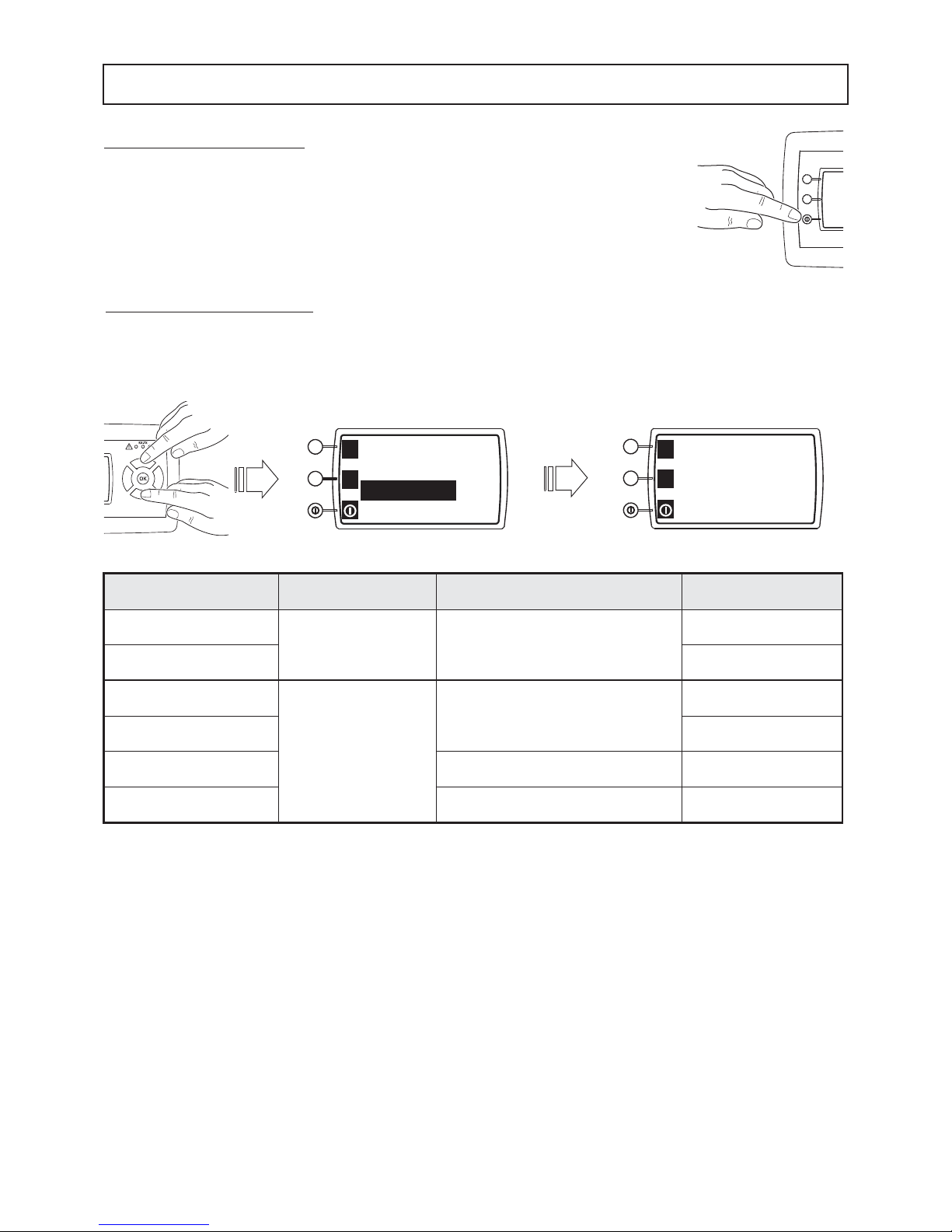
REMOTE OFF BY DIGITAL INPUT
To activate this function, select REM OFF enable from the main screen and with the joystick-menu buttons set YES.
NOTE: IF YOU ENABLE REM OFF BY DIGITAL INPUT WHILE THE UNIT IS ON, THE UNIT COULD SWITCH OFF IF THE
1_On/OffRem REMOTE DIGITAL INPUT IS OPEN.
MONITORING SYSTEM - User setting
CONTROL PANEL UNIT ON/OFF
To switch the machine on and off, press the “on/off” function button for a few seconds.
Unit ON-OFF
by control panel
REM OFF enable digital input: 1_On/Off REM Unit status
on
No
The unit status
not depends by digital input
on
off off
on
Yes
CLOSE (off)
on
off off
on OPEN (on) off
off
The unit status
not depends by digital input
off
 Loading...