

Page 1

i migliori gradi centigradi
MONITORING SYSTEM
FOR SERIES:
• RHV R134a
• RHV R407C BTZ
• RVW
• RLA
• RHA
INSTRUCTION MANUAL
Page 2

2
The manufacturer declines all responsibility for any inaccuracies in this manual due to printing or typing errors.
The manufacturer reserves the right to make changes and improvements to products in the catalog at any time and without notice.
Page 3

3
TABLE OF CONTENTS
MONITORING SYSTEM - User interface . . . . . . . . . . . . . . . . . . . . . . . . . . . . . . . . . . . . . . . . . . . . . . . . . . . . . . . . . . . . . . .5
CONTROL PANEL . . . . . . . . . . . . . . . . . . . . . . . . . . . . . . . . . . . . . . . . . . . . . . . . . . . . . . . . . . . . . . . . . . . . . . . . . . . .5
FUNCTION BUTTONS “F1”, “F2”, “F3”, “F4” AND “ON/OFF” . . . . . . . . . . . . . . . . . . . . . . . . . . . . . . . . . . . . . . . . . . .5
JOYSTICK BUTTON: “MENU”
. . . . . . . . . . . . . . . . . . . . . . . . . . . . . . . . . . . . . . . . . . . . . . . . . . . . . . . . . . . . . . . . . . .6
LED STATUS . . . . . . . . . . . . . . . . . . . . . . . . . . . . . . . . . . . . . . . . . . . . . . . . . . . . . . . . . . . . . . . . . . . . . . . . . . . . . . . .6
MONITORING SYSTEM - User menù . . . . . . . . . . . . . . . . . . . . . . . . . . . . . . . . . . . . . . . . . . . . . . . . . . . . . . . . . . . . . . . . . .7
COOLING MODE IR . . . . . . . . . . . . . . . . . . . . . . . . . . . . . . . . . . . . . . . . . . . . . . . . . . . . . . . . . . . . . . . . . . . . . . . . . . .7
HEATING MODE IP (reversible refrigerant side) . . . . . . . . . . . . . . . . . . . . . . . . . . . . . . . . . . . . . . . . . . . . . . . . . . . . .8
HEATING MODE IW (reversible water side) . . . . . . . . . . . . . . . . . . . . . . . . . . . . . . . . . . . . . . . . . . . . . . . . . . . . . . . .9
HEAT RECOVERY . . . . . . . . . . . . . . . . . . . . . . . . . . . . . . . . . . . . . . . . . . . . . . . . . . . . . . . . . . . . . . . . . . . . . . . . . . . .10
MONITORING SYSTEM - User setting . . . . . . . . . . . . . . . . . . . . . . . . . . . . . . . . . . . . . . . . . . . . . . . . . . . . . . . . . . . . . . . .11
CONTROL PANEL UNIT ON/OFF . . . . . . . . . . . . . . . . . . . . . . . . . . . . . . . . . . . . . . . . . . . . . . . . . . . . . . . . . . . . . . . .11
REMOTE OFF BY DIGITAL INPUT . . . . . . . . . . . . . . . . . . . . . . . . . . . . . . . . . . . . . . . . . . . . . . . . . . . . . . . . . . . . . . .11
CHANGE OPERATING MODE (hot / cooling) BY CONTROL PANEL . . . . . . . . . . . . . . . . . . . . . . . . . . . . . . . . . . . .13
CHANGE OPERATING MODE (SUMMER / WINTER) BY DIGITAL INPUT . . . . . . . . . . . . . . . . . . . . . . . . . . . . . . . .13
SETTING THE OPERATING SET POINT
. . . . . . . . . . . . . . . . . . . . . . . . . . . . . . . . . . . . . . . . . . . . . . . . . . . . . . . . . .15
TERMOREGULATION TIME PROPORTIONAL . . . . . . . . . . . . . . . . . . . . . . . . . . . . . . . . . . . . . . . . . . . . . . . . . . . . .16
HEAT RECOVERY . . . . . . . . . . . . . . . . . . . . . . . . . . . . . . . . . . . . . . . . . . . . . . . . . . . . . . . . . . . . . . . . . . . . . . . . . . . .18
IHEAT RECOVERY SETTING THE PARAMETERS . . . . . . . . . . . . . . . . . . . . . . . . . . . . . . . . . . . . . . . . . . . . . . . . . .19
STATE OF OPERATION . . . . . . . . . . . . . . . . . . . . . . . . . . . . . . . . . . . . . . . . . . . . . . . . . . . . . . . . . . . . . . . . . . . . . . . .21
DATE AND TIME . . . . . . . . . . . . . . . . . . . . . . . . . . . . . . . . . . . . . . . . . . . . . . . . . . . . . . . . . . . . . . . . . . . . . . . . . . . . .23
TIME SCHEDULING MANAGEMENT
. . . . . . . . . . . . . . . . . . . . . . . . . . . . . . . . . . . . . . . . . . . . . . . . . . . . . . . . . . . . .23
MONITORING SYSTEM - Alarms . . . . . . . . . . . . . . . . . . . . . . . . . . . . . . . . . . . . . . . . . . . . . . . . . . . . . . . . . . . . . . . . . . . . .26
ALARMS . . . . . . . . . . . . . . . . . . . . . . . . . . . . . . . . . . . . . . . . . . . . . . . . . . . . . . . . . . . . . . . . . . . . . . . . . . . . . . . . . . . .26
BIOS ALARMS . . . . . . . . . . . . . . . . . . . . . . . . . . . . . . . . . . . . . . . . . . . . . . . . . . . . . . . . . . . . . . . . . . . . . . . . . . . . . . .27
USER ALARMS . . . . . . . . . . . . . . . . . . . . . . . . . . . . . . . . . . . . . . . . . . . . . . . . . . . . . . . . . . . . . . . . . . . . . . . . . . . . . .28
AUTOMATIC ALARMS . . . . . . . . . . . . . . . . . . . . . . . . . . . . . . . . . . . . . . . . . . . . . . . . . . . . . . . . . . . . . . . . . . . . . . . . .30
ALARMS HISTORY . . . . . . . . . . . . . . . . . . . . . . . . . . . . . . . . . . . . . . . . . . . . . . . . . . . . . . . . . . . . . . . . . . . . . . . . . . .31
DISPLAYING THE ALARMS HISTORY
. . . . . . . . . . . . . . . . . . . . . . . . . . . . . . . . . . . . . . . . . . . . . . . . . . . . . . . . . . . .31
Page 4

4
Page 5

MONITORING SYSTEM - User interface
CONTROL PANEL
The control panel is composed of the instrument’s front panel, equipped with an LCD display, three indicator LEDs, and one joystick buttons and three function button, it enables viewing and/or checking the operating mode and parameters, resources and
complete alarm diagnostics.
In particular, it enables:
• Managing alarm situations
• Checking the status of resources.
KEY
1.Display
2. Alarms LED
3. LED for communication between the motherboard and the keypad
4. Power supply LED
5. Joystick Menu Buttons
6. Function Buttons
On pressing any of the buttons the display will light up for a few seconds; without pressing any of the buttons, the display will go
out after a few seconds. When switching on, the instrument will go into the state saved at the last machine shutdown or stand-by.
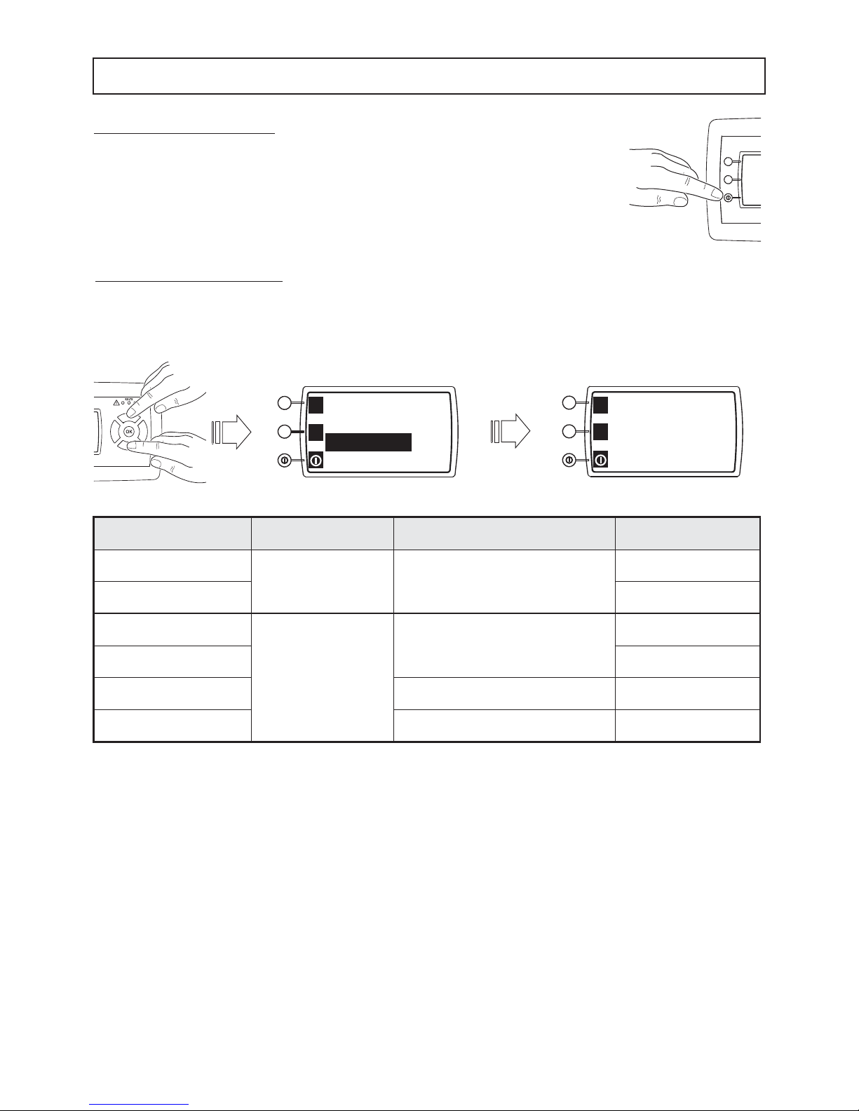
FUNCTION BUTTONS “F1”, “F2”, “F3”, “F4” AND “ON/OFF”
On the left of the keyboard there are 3 buttons whose function is shows on the
left of the LCD.
At POWER ON the LCD display shows the F1 (up), F2 (middle) and ON/OFF
(down) functions.
• By a single pressure of ON/OFF button: the keyboard displaying change:
F1 became F3 (up button) and F2 became F4 (middle button). The ON/OFF
(down) button doesn’t change.
By a new pressure on ON/OFF button, the keyboard displaying change and
show the previous situation:
F1, F2 and ON/OFF.
• BY PUSHING FOR SOME SECONDS THE ON/OFF BUTTON:
THE MACHINE ON-OFF (ON-OFF)
Using the buttons, the function of which is shown on the display, you can directly access main functions:
• Pressing a single time: shows the ma
in menu on the display.
• Pressing for a few seconds: directly access the menu associated with that
particular position.
KEY F1 : show the INPUTS and OUTPUTS resources of system control.
KEY F2 :
show the PARAMETER submenu (for the service only, with password).
KEY F3 : show the ALARMS submenu.
KEY F4 : show the COMPRESSOR submenu.
CAUTION: IF THE ALARM SIGNAL “RTC” (REAL TIME CLOCK) APPEARS WHEN STARTING FOR THE FIRST TIME, SET
THE DATE AND TIME IN THE RESPECTIVE “DATE AND TIME” MENU.
1234
5
6
17:25 01/03
Cool
Water IN 12.0°C
Water OUT 7.0°C
F1
F2
5
F1
F2
F3
F4
Page 6

LED STATUS
LEDs ( )
The first LED (green) indicates there is supply voltage:
• LED ON means that the controller is powered
• LED OFF means that the controller is not powered
LED (RX-TX)
The second LED (amber) indicates there is communication between the controller and the keypad:
• ON when there is communication
• OFF when there is no communication
LED ( )
The third LED (red) indicates there are alarms:
• ON if there is at least one active alarm
• OFF if there are no active alarms
• BLINKING if there are alarms that have ended but have not yet been manually reset.
• BLINKING without alarms to indicate that:
- function HPP (High Pressure Prevention) is active (RHV - RVW units)
- function ATC (Advanced Temperature Control) is active (RLA - LFL unit)
- function PRE-ALARM HIGH PRESSURE is active (RLA - LFL unit)
- function PRE-ALARM LOW PRESSURE is active (RLA - LFL unit).
The alarm reset procedure is explained in paragraph MONITORING SYSTEM - ALARMS
6
• Position UP: scrolls through the menu
items upwards or increases the value of a
parameter.
• Position DOWN: scrolls through the
menu items downwards or decreases the
value of a parameter.
• Position LEFT (ESC): returns to the
previous menu.
• Position RIGHT: moves into the sub-
menu, confirms an action, enters editing a value or again confirms a changed
value.
N.B. PRESSING THE (ENTER) BUTTON IN THE MIDDLE CONFIRMS THE COMMAND OR
ACCESSES THE DISPLAYED MENU.
JOYSTICK BUTTON: “MENU”
Used to scroll through the menus by acting on the four positions (UP; DOWN; LEFT; RIGHT) pressing a single time; in particular:
MONITORING SYSTEM - User interface
Page 7

7
When the unit switches on, the display shows the first page of the main screen.
On the top line there is the current time (17:25) and the page no. (1/4 comprising
the screen.
-
“Standby” indicate the state of operation of the unit (Standby, cooling, shutdown).
- “Water IN” indicate the temperature of inlet evaporator.
- “Water OUT” indicate the temperature of the outlet evaporator.
Pressing the DOWN button takes you to page 02/04
- “Power” show the power output from the unit.
- “Set Point 1” the set point adjustment.
- “Band 1” the band adjustment
By using the UP/DOWN-ENTER buttons to select the Set point 1 and/or Band 1 line,
it is possible to change the adjustment settings.
17:25 01/04
Standby
Water IN
12.0°C
Water OUT
7.0°C
02/04
Power 70%
Set Point 1
7.0°C
Band 1 1.0°C
03/04
Real Set 7.0°C
REM OFF enable
NO
Menu
04/04
Reserved menu
COOLING MODE IR
Pressing the DOWN button takes you to page 03/04.
- “Real Set” indicate the current point of adjustment.
- “REM OFF enable” enable switch off the unit via digital input. This function has
priority over keypad commands. On the RH side of the display YES/NO appears
depending on the enabling of Remote OFF.
- “Menu” indicate the access point to the user menu. Pressing Enter, with the
UP/DOWN buttons it is possible to access the following pages (see the table).
Pressing the DOWN button takes you to page 04/04.
-“Reserved menu” is reserved for the support service.
DISPLAY DESCRIPTION
Page 1 of 3
Inputs and outputs
Displays the status and values of the digital and analog inputs/outputs
Alarms Used to see and/or reset the status of the alarms
Date and time Used to set the current date and time
Page 2 of 3
Pumps Used to see the activation status of the pumps
Circuits Used to see the activation status of the circuits
Compressors Used to see the activation status of the compressors
Page 3 of 3
Condenser
(water condenser)
Fans
(air condenser)
Used to see the state of condensation control
Used to see the state of fans control
Time scheduling Used to set the operating time scheduling
Language selection Used to select the language (english by default)
MENU 01/03
Inputs and outputs
alarms
Date and time
MENU 02/03
Pumps
Circuits
Compressor
MENU 03/03
Condenser / Fans
Time scheduling
Language selection
F1
F2
F1
F2
F1
F2
F1
F2
F1
F2
F1
F2
F1
F2
MONITORING SYSTEM - User menù
Page 8

8
When the unit switches on, the display shows the 4 page of the main screen
On the top line there is the current time (17:25) and the page no. (1/4 comprising the
screen.
- “Standby” indicate the state of operation of the unit (standby, cooling, hot, shutdown).
- “Water IN” indicate the temperature of inlet evaporator.
- “Water OUT” indicate the temperature of the outlet evaporator.
Pressing the DOWN button takes you to page 02/04
- “Power” indicate the power delivered by the unit.
- “Set Point 1” the set point adjustment.
- “Band 1”, the band of
adjustment
.
By using the UP/DOWN-ENTER buttons to select the Set point 1 it is possible to
change the adjustment settings.
17:25 01/04
Standby
Water IN
40.0°C
Water OUT
45.0°C
02/04
Power 70%
Set Point 1
45.0°C
Band 1 1.0°C
03/04
Local mode Hot
Real Set 45.0°C
REM S/W enable NO
04/04
REM OFF enable
NO
Menu
Reserved menu
HEATING MODE IP (reversible refrigerant side)
Pressing the DOWN button takes you to page 03/04.
- “Local mode”, selection of the mode of operation by control panel.
- “Real Set”, indicate the current point of adjustment.
- “
REM S/W enable” enable mode change of the unit via digital input. This func-
tion has priority over keypad commands. On the RH side of the display YES/NO
appears depending on the enabling of REM S/W.
By using the UP/DOWN-ENTER buttons to select the
“Local mode” it is possible
to change the Mode of operation (HOT-COOLING
) of unit.
Pressing the DOWN button takes you to page 04/04.
- “REM OFF enable” enable switch off the unit via digital input. This function has
priority over keypad commands. On the RH side of the display YES/NO appears
depending on the enabling of REM OFF.
- “Menu” indicate the access point to the user menu. Pressing Enter, with the
UP/DOWN buttons it is possible to access the following pages (see the table).
-“Reserved menu” is reserved for the support service.
DISPLAY DESCRIPTION
Page 1 of 3
Inputs and outputs
Displays the status and values of the digital and analog inputs/outputs
Alarms Used to see and/or reset the status of the alarms
Date and time Used to set the current date and time
Page 2 of 3
Pumps Used to see the activation status of the pumps
Circuits Used to see the activation status of the circuits
Compressors Used to see the activation status of the compressors
Page 3 of 3
Fans Used to see the state of fans control
Time scheduling Used to set the operating time scheduling
Language selection Used to select the language (english by default)
MENU 01/03
Inputs and outputs
alarms
Date and time
MENU 02/03
Pumps
Circuits
Compressor
MENU 03/03
Fans
Time scheduling
Language selection
F1
F2
F1
F2
F1
F2
F1
F2
F1
F2
F1
F2
F1
F2
MONITORING SYSTEM - User menù
Page 9

9
When the unit switches on, the display shows the first page of the main screen
On the top line there is the current time (17:25) and the page no. (1/5 comprising the
screen.
-
“Standby” indicate the state of operation of the unit (Standby, cooling, hot, shutdown).
- “Water IN” indicate the temperature of inlet evaporator.
- “Water OUT” indicate the temperature of the outlet evaporator.
Pressing the DOWN button takes you to page 02/05
- “Cond. Out” indicate the temperature of the outlet condenser.
- “Power” show the power output from the unit.
- “Set Point 1” the set point adjustment.
By using the UP/DOWN-ENTER buttons to select the Set point 1 it is possible to
change the adjustment settings.
17:25 01/05
Standby
Water IN
12.0°C
Water OUT
7.0°C
02/05
Cond. Out 42.0°C
Power 70%
Set Point 1
7.0°C
03/05
Band 1 1.0°C
Local mode Hot
Real Set 45.0°C
04/05
REM S/W enable NO
REM OFF enable
NO
Menu
05/05
Reserved menu
HEATING MODE IW (reversible water side)
Pressing the DOWN button takes you to page 03/05.
- “Band 1”, the band 1 of adjustment.
- “Local mode”, selection of the mode of operation by control panel.
- “Real Set”, indicate the current point of adjustment.
By using the UP/DOWN-ENTER buttons to select the
“Band 1” it is possible to
change the band regolation.
By using the UP/DOWN-ENTER buttons to select the
“Local mode” it is possible
to change the Mode of operation (HOT-COOLING
) of unit.
Pressing the DOWN button takes you to page 04/05.
- “
REM S/W enable” enable mode change of the unit via digital input. This func-
tion has priority over keypad commands. On the RH side of the display YES/NO
appears depending on the enabling of REM S/W.
- “REM OFF enable” enable switch off the unit via digital input. This function has
priority over keypad commands. On the RH side of the display YES/NO appears
depending on the enabling of REM OFF .
- “Menu” indicate the access point to the user menu. Pressing Enter, with the
UP/DOWN buttons it is possible to access the following pages (see the table).
DISPLAY DESCRIPTION
Page 1 of 3
Inputs and outputs
Displays the status and values of the digital and analog inputs/outputs
Alarms Used to see and/or reset the status of the alarms
Date and time Used to set the current date and time
Page 2 of 3
Pumps Used to see the activation status of the pumps
Circuits Used to see the activation status of the circuits
Compressors Used to see the activation status of the compressors
Page 3 of 3
Condenser Used to see the state of condensation control
Time scheduling Used to set the operating time scheduling
Language selection Used to select the language (english by default)
MENU 01/03
Inputs and outputs
alarms
Date and time
MENU 02/03
Pumps
Circuits
Compressor
MENU 03/03
Condenser
Time scheduling
Language selection
F1
F2
F1
F2
F1
F2
F1
F2
F1
F2
F1
F2
F1
F2
F1
F2
MONITORING SYSTEM - User menù
Pressing the DOWN button takes you to page 05/05.
-“Reserved menu” is reserved for the support service.
Page 10

10
DISPLAY DESCRIPTION
Page 1 di 4
Inputs and outputs
Displays the status and values of the digital and analog inputs/outputs
Alarms Used to see and/or reset the status of the alarms
Date and time Used to set the current date and time
Page 2 di 4
Pumps Used to see the activation status of the pumps
Circuits Used to see the activation status of the circuits
Compressors Used to see the activation status of the compressors
Page 3 di 4
Condenser Used to see the state of condensation control
Heat Recovery Used to see the state of heat recovery
Time scheduling Used to set the operating time scheduling
Page 4 di 4
Language selection Used to select the language (english by default)
When the unit switches on, the display shows the first page of the main screen
On the top line there is the current time (17:25) and the page no. (1/4 comprising
the screen.
- “Standby” indicate the state of operation of the unit (standby, cooling, shutdown).
- “Water IN” indicate the temperature of inlet evaporator.
- “Water OUT” indicate the temperature of the outlet evaporator.
Pressing the DOWN button takes you to page 02/04
- “Power” show the power output from the unit.
- “Set Point 1” the set point adjustment.
- “Band 1” the band adjustment.
By using the UP/DOWN-ENTER buttons to select the Set point 1 and/or Band 1
line, it is possible to change the adjustment settings.
17:25 01/04
Standby
Water IN
12.0°C
Water OUT
7.0°C
02/04
Power 70%
Set Point 1
7.0°C
Band 1 1.0°C
03/04
Real Set 7.0°C
Recovery
41.0°C
REM OFF enable
NO
04/04
Menu
Reserved menu
HEAT RECOVERY
Pressing the DOWN button takes you to page 03/04.
- “Real Set” indicate the current point of adjustment.
- “Recovery” indicate the inlet heat recovery temperature.
- “REM OFF enable” enable switch off the unit via digital input. This function has
priority over keypad commands. On the RH side of the display YES/NO appears
depending on the enabling of REM OFF .
Pressing the DOWN button takes you to page 04/04.
- “Menu” indicate the access point to the user menu. Pressing Enter, with the
UP/DOWN buttons it is possible to access the following pages (see the table).
-“Reserved menu” is reserved for the support service.
MENU 01/03
Inputs and outputs
Alarms
Date and time
MENU 02/03
Pumps
Circuits
Compressor
MENU 03/04
Condenser
Heat Recovery
Time scheduling
MENU 04/04
Language selection
F1
F2
F1
F2
F1
F2
F1
F2
F1
F2
F1
F2
F1
F2
F1
F2
MONITORING SYSTEM - User menù
Page 11
11
REM. ON/OFF ENABLE
YES
F1
F2
Real Set 7.0°C
REM OFF enable
NO
Menu
F1
F2
REMOTE OFF BY DIGITAL INPUT
To activate this function, select REM OFF enable from the main screen and with the joystick-menu buttons set YES.
NOTE: IF YOU ENABLE REM OFF BY DIGITAL INPUT WHILE THE UNIT IS ON, THE UNIT COULD SWITCH OFF IF THE
1_On/OffRem REMOTE DIGITAL INPUT IS OPEN.
MONITORING SYSTEM - User setting
CONTROL PANEL UNIT ON/OFF
To switch the machine on and off, press the “on/off” function button for a few seconds.
Unit ON-OFF
by control panel
REM OFF enable digital input: 1_On/Off REM Unit status
on
No
The unit status
not depends by digital input
on
off off
on
Yes
CLOSE (off)
on
off off
on OPEN (on) off
off
The unit status
not depends by digital input
off
Page 12

12
MONITORING SYSTEM - User menù
RECOMMENDED SETTINGS : to configure correctly the function ON / OFF from digital input, follow the following guidelines :
CAUTION : THESE OPERATIONS MUST BE PERFORMED BY QUALIFIED PERSONNEL.
- Sure that the parameter REM OFF Enable is set to NO (figura 1).
- Turn off the unit from the control panel and wait until it is displayed the writing Standby.
- Remove power to the electrical panel by bringing the door lock switch in position “0”.
- connect the remote contact to the user terminal within the electrical panel and make sure that contact is closed.
(ref. Electrical schematic of the unit).
- Close the electrical panel.
- Apply power to the electrical panel by bringing the door lock switch in position "1".
- Press the ON / OFF button on the control panel to turn on the machine.
At this point the machine is turned on and is ready to turn the compressors to meet the set-point set.
- Set the parameter REM OFF enable at YES. In this way, digital off contact is enabled.
Opening the contact On/Off REM the unit before shutting down and then in standby.
F1
F2
Real set 7.0°C
REM S/W enable
NO
REM OFF enable
NO
17:25 01/04
Standby
Water IN 12.0°C
Water OUT 7.0°C
F1
F2
17:25 01/04
Standby
Water IN 12.0°C
Water OUT 7.0°C
F1
F2
17:25 01/04
Cooling
Water IN 12.0°C
Water OUT 7.0°C
F1
F2
REM ON/OFF ENABLE
YES
F1
F2
Real Set 7.0°C
REM OFF enable
NO
Menu
F1
F2
Page 13

13
MONITORING SYSTEM - User setting
REMOTE S/W ENABLE
YES
F1
F2
Real Set 7.0°C
REM
S/W enable
NO
REM OFF enable
NO
F1
F2
CHANGE OPERATING MODE (SUMMER / WINTER) BY DIGITAL INPUT
To activate this function, select REM S/W enable from the main screen and with the joystick-menu buttons set YES.
NOTE: IF YOU ENABLE REM S/W WHILE THE UNIT IS TURNED ON, THE UNIT COULD SWITCH OFF AND CHANGE THE
MODE OF OPERATION IF THE DIGITAL INPUT REM S/W IS OPEN.
LOCAL S/W MODE
COOLING
F1
F2
Set point 1 7.0°C
Band 1
1.0°C
Local mode
COOLING
F1
F2
CHANGE OPERATING MODE (hot / cooling) BY CONTROL PANEL
To change the operation mode (hot / cooling) by control panel, select LOCAL MODE from the main screen.
NOTE: THE CHANGE, OF THE OPERATION MODE BY CONTROL PANEL HAS A PRIORITY MORE LOW COMPARED TO
CHANGE THE OPERATION MODE BY DIGITAL INPUT: IF THE DIGITAL INPUTS S/W REM IS OPEN THE UNIT WORK IN
HEAT PUMP REGARDLESS TO CHANGE OPERATING MODE BY CONTROL PANEL.
THE CHANGE OPERATING MODE FROM DIGITAL INPUT HAS PRIORITIES IN RELATION TO CHANGE OPERATING
MODE FROM KEYBOARD: IF THE DIGITAL INPUTS S/W REM IS OPEN THE UNIT WORK IN HEAT PUMP REGARDLESS
TO CHANGE OPERATING MODE FROM KEYBOARD.
Local mode
by control panel
REM S/W enable digital input: 14_S/W REM
Mode of operation
of unit
Cooling
NO
the mode of operation of unit,
not depends by digital input
Cooling
Hot Hot
Cooling
YES CLOSE (off) Cooling
Hot
Cooling
YES OPEN (on) Hot
Hot
Page 14

14
MONITORING SYSTEM - User menù
RECOMMENDED SETTINGS : to properly configure the change mode of operation by digital input, try the following:
CAUTION: THESE OPERATIONS MUST BE PERFORMED BY QUALIFIED PERSONNEL
-Sure that the parameter REM S/W Enable is set to NO.
-Turn off the unit from the control panel and wait until it is displayed the writing Standby.
-Remove power to the board by bringing the door lock switch in position "0".
- Connect the remote contact (summer / winter) to the user terminal within the electrical panel and make sure that contact
is close. (Electrical schematic of the unit).
- Close the electrical panel.
- Apply power to the electrical panel by bringing the door lock switch in position "1"
- Wait for the main page on the control panel.
- Set the local mode of operation at Cooling.
-Set the parameter REM S/W Enable at YES.
(Note: If you set REM S/W Enable = YES and the remote contact Summer / Winter is
- CLOSED (off): the unit is ready for operation at cooling mode
- OPEN (on): 4-way valves immediately reverse cycle-switching
and the unit will be ready for operation at heat-pump mode)
TO PRESS THE ON/OFF BUTTON ON THE CONTROL PANEL, THE UNIT AUTOMATICALLY BEGINS TO OPERATE IN A
MODE ESTABLISHED BY REM S/W DIGITAL CONTACT.
F1
F2
Real set 7.0°C
REM S/W enable
NO
REM OFF enable
NO
17:25 01/04
Standby
Water IN 12.0°C
Water OUT 7.0°C
F1
F2
F1
F2
03/04
Local mode
Cooling
Real set
45.0°C
REM S/W enable
NO
F1
F2
03/04
Local mode
Cooling
Real set
45.0°C
REM S/W enable
YES
Page 15

15
MONITORING SYSTEM - User setting
SETTING THE OPERATING SET POINT
From the main screen, press the “Up” and “Down” buttons to access Set Point 1 and press ENTER: the “Setpoint 1 chiller
mode” screen will appear. Press ENTER to make the temperature value 7.0°C blink and change it with the “Up” and “Down”
buttons as required. Press ENTER to confirm.
To return to the main screen, press the
LEFT (ESC)
LEFT (ESC) button several times:
Power 70%
Set Point 1 7.0°C
Band 1 1.0°C
CH SET 1 01/01
Setpoint 1
chiller mode
7.0°C
F1
F2
F1
F2
To modify the Band 1 proceed in a similar manner to the one described for setting the operating SET POINT.
IMPORTANT NOTE:
In “time proportional regulation” is reccomended to keep the band=1°C.
Page 16

16
TICP: Chiller INC power time (TIME INCREASING COOLING POWER)
TDCP:
Chiller DEC power time (TIME DECREASING COOLING POWER)
CB: COOLING BAND
SET POINT: SET POINT TEMPERATURE IN COOLING
The function of the regulator consists in activating a number of resources (power step) in proportion to the time that the evaporator water outlet by spends beyond the threshold given by CHILLER SETPOINT + (BAND / 2). The band is symmetric with
respect to the value of CHILLER SETPOINT.
When the temperature has exceeded the threshold value for the duration of the parameter CHILLER INC POWER TIME, activate a power step. If the temperature of evaporator water outlet by remains above the threshold value for further TEMPO
POWER INCREASE IN COLD, is another power step.
If the temperature of evaporator water outlet by remain within the temperature range determined by CHILLER SETPOINT +
(BAND / 2) and CHILLER SETPOINT - (BAND / 2) the power output from the machine remains constant.
If the temperature of evaporator water outlet by remains below the threshold CHILLER SETPOINT - (BAND / 2) for the time
given by the parameter CHILLER DEC POWER TIME is a step off power.
In this algorithm there is no hysteresis.
TERMOREGULATION TIME PROPORTIONAL
COOLING MODE (IR)
MONITORING SYSTEM - User setting
TEMPERATURE
WATER OUTLET
TIPF TIPF
+1 +1 +1-1 -1 -1
TDPF TDPF TDPF
TIME
Set
Point
CB
TEMPERATURE READ BY
EVAPORATOR
WATER OUTLET PROBE
CHILLER setpoint
+(BAND / 2).
CHILLER setpoint
- (BAND / 2).
TICP
TDCP
TDCP
TDCP
TICP
Page 17

17
HEATING MODE (IP / IW)
MONITORING SYSTEM - User setting
The function of the regulator consists in activating a number of resources (power step) in proportion to the time that the evaporator water outlet by spends below the threshold given by HEAT PUMP SETPOINT - (BAND / 2). The band is symmetric with
respect to the value of HEAT PUMP SETPOINT.
When the temperature remains below the threshold value for the duration of the parameter HEAT PUMP INC POWER TIME,
activate a power step. If the temperature of evaporator water outlet by remains below the threshold value for further HEAT PUMP
INC POWER TIME, is another power step.
If the temperature of evaporator water outlet by remain within the temperature range determined by HEAT PUMP SETPOINT +
(BAND / 2) and HEAT PUMP SETPOINT - (BAND / 2) the power output from the machine remains constant.
If the temperature of evaporator water outlet by remains above the threshold HEAT PUMP SETPOINT + (BAND / 2) for the time
given by the parameter HEAT PUMP DEC POWER TIME is a step off power.
In this algorithm there is no hysteresis.
+1 +1 +1-1 -1 -1
TIHP: Chiller INC power time (TIME INCREASING HEATING POWER)
TDHP:
Chiller DEC power time (TIME DECREASING HEATING POWER)
HB: HEATING BAND
SET POINT: SET POINT TEMPERATURE IN HEATING
TEMPERATURE
WATER OUTLET
TIME
Set
Point
HB
HEATPUMP setpoint
+ (BAND / 2).
HEATPUMP setpoint
- (BAND / 2).
TEMPERATURE READ BY
CONDENSER
WATER OUTLET PROBE
TDHP
TIHP
TIHP TIHP
TDHP
Page 18

18
HEAT RECOVERY
The recovery function heats water using heat from the condenser that otherwise would be dispersed in the environment:
- In air (air-water units)
- In water (water-water units)
When the machine is in cooling mode (compressors on), if the water in the recovery circuit is of a sufficiently low temperature
to require heat, the machine switches from normal to recovery mode.
When the water temperature reaches the recovery set point, the machine switches back to normal operating mode.
Switching from normal operation to heat recovery and vice versa, takes place:
- respecting the minimum time of operation set for the two modes
- minimize compressor power (screw compressor).
MONITORING SYSTEM - User setting
- AIR-WATER UNIT WATER-WATER UNIT
PARTIAL HEAT
RECOVERY
VP
Units in water-water condensation is unique
for all circuits refrigerator and heat recovery
is always TOTAL.
TOTAL HEAT
RECOVERY
VR
OFF
ON
T
BANDA PROP.
SET
SET - recovery set-point PROP. BAND - proportional band T: Temperature measured by sensor at recovery water inlet
OFF
ON2
ON1
BANDA PROP.
SET
T
OFF
ON
T
BANDA PROP.
SET
PROP. BAND
PROP. BAND
PROP. BAND
Page 19

19
ENABLE
Serves to enable the Recovery function.
Using the MENU joystick buttons, select ENABLE .
RECOVERY
01/02
ENABLE YES
SETPOINT
41.0°C
PROP BAND
2.0°C
F1
F2
RECOVERY ENABLE
YES
F1
F2
To change the YES/NO status, press “Enter” twice:
the value YES will start flashing
- change the value as required using the “Up/Down”buttons.
After changing the value, press “Enter” to confirm and then press “Left” to exit.
SET-POINT
Using the MENU joystick buttons, select the SET POINT parameter.
This parameter is set by default to 41.0 °C.
RECOVERY
01/02
ENABLE YES
SETPOINT
41.0°C
PROP BAND
2.0°C
F1
F2
RECOVERY SETPOINT
41.0°C
F1
F2
To change this set-point value, press “Enter” twice:
the value 41.0 ºC will start flashing
- change the set-point value as required using the “Up/Down” buttons.
After changing the value, press “Enter” to confirm and then press “Left” to exit.
MONITORING SYSTEM - User setting
HEAT RECOVERY SETTING THE PARAMETERS
To access the operating parameters for heat Recovery mode, bring on the start screen, scroll through the pages to select the
"Recovery" and press ENTER.
The following items will appear on the display:
•
ENABLE
•
SET-POINT
• PROP. BAND
•
REMOTE
17:25
Off
Water IN 12.0°C
Water OUT 7.0°C
Working Set 7.0°C
Recovery
40.0°C
REM ON-OFF
YES
F1
F2
RECOVERY
01/02
ENABLE YES
SETPOINT
41.0°C
PROP BAND
2.0°C
F1
F2
RECOVERY
02/02
REMOTE YES
F1
F2
F1
F2
Page 20

20
PROP. BAND
Using the MENU joystick buttons, select the PROP. BAND parameter.
This parameter is set by default to 2.0 °C.
RECOVERY
02/02
REMOTE YES
F1
F2
RECOVERY
01/02
ENABLE YES
SETPOINT
41.0°C
PROP BAND
2.0°C
F1
F2
RECOVERY
01/02
ENABLE YES
SETPOINT
41.0°C
PROP BAND
2.0°C
F1
F2
RECOVERY PROP BAND
2.0°C
F1
F2
REM RECOVERY ENABLE
YES
F1
F2
To change this set-point value, press “Enter” twice:
the value 2.0 °C will start flashing
- change the value as required using the “Up/Down”buttons.
After changing the value, press “Enter” to confirm and then press “Left” to exit.
REMOTE
Allows the Recovery function to be enabled from a remote digital input.
Using the MENU joystick buttons, select the REMOTE parameter.
To change the YES/NO status press “Enter”twice:
the value will start flashing
- change the value as required using the “Up/Down”buttons.
After changing the value, press “Enter” to confirm and then press “Left” to exit.
MONITORING SYSTEM - User setting
Page 21

21
STATE OF OPERATION
To know the machine’s operating status, scroll through the main menu down to the bottom and select “menu”, then press “Enter”.
03/04
Real Set 7.0°C
REM OFF enable
NO
Menu
F1
F2
Use the Up and Down buttons to scroll through the menu to display the items:
Under “Inputs and outputs”, there will be the state of the physical inputs of the control
system:
• Analog inputs (temperature probes, pressure transducers)
• Digital inputs (thermal protection, protection water flow, input of control)
• Analog outputs (signals to control fans)
• Digital outputs (relay control)
Under “alarms”, there will be the information needed to verify alarms and reset the unit:
• bios alarms
• user alarms
• automatic alarms
• history
• reset alarms
Under “date and time”,there will be the information for setting the time and date.
Under “Pumps”, there will be a list of the machine’s pumps and for each one of them:
• Operating status
• Days of operation
• Hours of operation
• Pump enable
Under “Circuits” there will be a list of the machine’s circuits and, for each one of them, there will be displayed:
• The compressor suction pressure read by the low-pressure transducer (if present)
• The compressor discharge pressure read by the high-pressure transducer (if present)
• The current operating status (alarm or power)
• The power of the circuits
• Condensation temperature
• The HPP’s status - High Pressure Prevention (only RHV / WSH / RVW unit)
• The ATC’s status - Advanced Temperature Control (only RLA / LFL / WRL unit)
MONITORING SYSTEM - User setting
MENU
Inputs and outputs
Alarms
Date and time
MENU
Pumps
Circuits
Compressors
MENU
Condenser
Fans
Heat recovery
F1
F2
F1
F2
F1
F2
MENU
Time scheduling
Language selection
F1
F2
Page 22

22
MONITORING SYSTEM - User setting
Under “Compressor” there will be a list of the machine’s compressors and, for each one of them, there will be displayed:
• The current state of operation (power or alarm)
• Power output expressed as a %
• Compressor discharge temperature
• Hours of operation
• Days of operation
• Compressor enable
Under “Condenser” there will be the percente of condensing control (water-water unit).
Under "Fans" will list the bench and fans for each of them, will be displayed:
• speed of operation, expressed in %
Under the heading "Heat Recovery" will list the condensers for the heat recovery and for each of them, will be displayed:
• recovery enable
• the power expressed in %
• input temperature
Under "time scheduling", will be settings for configuring the time scheduling.
Under "Language Selection", gives us the opportunity to change the user menu language:
- 0 = italian
- 1 = english
Page 23

23
TIME SCHEDULING MANAGEMENT
The control panel allows you to program the time scheduling of the unit.
PREMISE:
For the correct working of the time scheduling is necessary to set up current day and hour
Time scheduling setup can be done by logging on to the submenu. :
DATE AND TIME
The “Date and time” menu is used to set the date and time on the instrument.
To set the date and time, go to the “Date and time” menu with the joystick-Menu buttons.
MONITORING SYSTEM - User setting
03/04
Real Set
7.0°C
REM OFF enable
NO
Menu
F1
F2
MENU 01/03
Inputs and outputs
Alarms
Date and time
F1
F2
DATE & TIME 01/01
12/02/09 15:35
Date Modify
Hour Modify
F1
F2
TIMER TYPE = 0: “Time scheduling Daily”: With this timer type you can select a different time scheduling for each day of the
week. Under SETUP line you can set up max 4 time bands- singularly activable- for each different day of the week.
TIMER TYPE = 1: “Time scheduling Weekly” : With this timer type for all days the unit will work with the same time scheduling. Under SETUP line you can set up max 4 time bands- singularly activable- for all the days of the week.
TIMER TYPE = 2: “Time scheduling Week end (5+2)” : With this timer type you can select 2 different time scheduling: one for
working days and one for weekend. Under SETUP line you can set up max 4 time bands- singularly activable- for the working
days (from Monday to Friday) and for the weekend days (Saturday and Sunday).
Real Set
7.0°C
REM OFF enable
NO
Menu
F1
F2
MENU
Condenser
Time scheduling
Language selection
F1
F2
MONDAY TUESDAY
WEDNESDAY
THURSDAY FRIDAY SATURDAY SUNDAY
Time band 1
Time band 2
Time band 3
Time band 4
WEEKLY
Time band 1
Time band 2
Time band 3
Time band 4
MONDAY - FRIDAY SATURDAY- SUNDAY
Time band 1
Time band 2
Time band 3
Time band 4
TIME SCHEDULING
01/01
Timer NO
Time type
0
Setup
F1
F2
NO time scheduling disable
YES time scheduling enable
0
Time scheduling
Daily
1
Time scheduling
Weekly
2
Time scheduling
Week end
(5+2)
Page 24

24
After timer type set you have to go to SETUP line to actually setup the start, the end, the unit mode and water temp setup for
each time band.
SETUP: according to the different timer type selected on the display there will be different lines:
IMPORTANT NOTE
For the chiller working, the time scheduling setup is always priority on the setup done by keyboard control, except the
remote ON/OFF by digital input
The digital input remote ON/OFF -IF ENABLED
- is always priority on time scheduling:
If the unit is in OFF mode by remote (remote ON/OFF) and the time scheduling are enabled the unit remains OFF. When
you switch ON the unit by remote ON/OFF the unit starts to work following the time scheduling setup.
Time scheduling management is disabled even if the configuration mode is activated.
For instance for TIMER TYPE = 0 (daily) in submenu SETUP you have to move on MONDAY line then press ENTER and so
setup for each time band the parameters showed:
TIME BAND 1 ENABLE FLAG: this parameter enable/disables the first time band
TIME BAND 1 HOUR: this parameter allows the setting of the start hour of the first time band
TIME BAND 1 MINUTES: this parameter allows the setting of the start minutes
(from 0 to 59 inside the time band hour) of the first time band.
TIMER TYPE = 0 (Daily)
TIMER TYPE = 1 (Weekly)
TIMER TYPE = 3 (Week-end 5+2)
SETUP 01/03
Monday
Twesday
Wednesday
SETUP 02/03
Thursday
Friday
Saturday
SETUP 03/03
Sunday
F1
F2
F1
F2
SETUP 01/01
Weekly
F1
F2
SETUP 01/01
Monday - Friday
Saturday - Sunday
F1
F2
MONDAY 01/24
Time band 1
enable flag
SI
F1
F2
MONDAY 02/24
Time band 1
HOUR
15 h
F1
F2
MONDAY 03/24
Time band 1
MINUTES
25 Min
F1
F2
F1
F2
MONITORING SYSTEM - User setting
Page 25

25
TIME BAND 1 MODE: this parameter allows the setting of the unit operation mode in
the first time band:
1 = OFF
Enabling this mode the unit is off and it is not possible to switch on neither by display
user interface nor by digital input (for instance by remote)
2 = COOLING
Enabling this mode the unit is on and in cooling mode. The water set point is the value fixed
on TIME BAND 1 CH TEMP SETPOINT It is not possible to switch off the unit by dis-
play user interface, but only by digital input (Remote ON/OFF) - if activated -
3 = MANUAL MODE (not used)
4 = LOCAL SET (only cool)
Enabling this mode the unit is on and in cooling mode.
The water set point is the value fixed by display user interface (we can define standard
set point). It is not possible to switch off the unit by display user interface, but
only by digital input (Remote ON/OFF) - if activated -.
TIME BAND 1 CH TEMP SETPOINT:
This parameter allows the setting on chiller mode (CH) of the water temperature set
point.
TIME BAND 1 HP TEMP SETPOINT: not used for only cooling units.
This parameter can be used only for heat pump (HP) units: it allows the setting on
heat pump mode of the water temperature set point.
For each operating mode the standard set point is stored in a non volatile memory of the control board and it will be
used again by the unit when the time scheduling are disabled.
MONDAY 04/24
Time band 1
MODE
1
F1
F2
MONDAY 05/24
Time band 1
CH TEMP SETPOINT
7.0°C
F1
F2
MONDAY 05/24
Time band 1
HP TEMP SETPOINT
45.0°C
F1
F2
MONITORING SYSTEM - User setting
Page 26

26
ALARMS
The alarms menu is used to display and reset any active alarms and display the alarm log.
There are 2 different ways of accessing the alarms menu:
Mode 1: Scroll through the main menu down to the bottom and select “Menu”, then press “Enter”, then select “Alarms” and press
“Enter”.
ALARMS 01/02
BIOS Alarms
USER Alarms
Alarms Reset
F1
F2
ALARMS 02/02
History
Automatic Alarms
F1
F2
Mode 2: Press and hold down button F3 for a few seconds.
The alarm menu is displayed as follow
1° VIEW 2° VIEW
Select the relevant item and press “Enter”.
•
When an alarm is present, the red led is ON.
•
When an alarm is resettable, the red led is blinking.
• In order to reset an alarm, select “alarm reset” and press ENTER.
Real Set 7.0°C
REM OFF enable
NO
Menu
F1
F2
MENU
Inputs and outputs
alarms
Date and time
F1
F2
MONITORING SYSTEM - Alarms
F1
F2
F3
F4
F3
F4
Page 27

27
BIOS ALARMS
They solely concern HW and SW operation of the micro-controller and do not involve the machine components (compressors,
pumps, sensors, etc.)
After selecting the bios alarms menu, all active bios alarms are displayed.
The bios alarms can end automatically or can last until operator intervention.
For example: The RTC battery alarm (RTC= Real Time Clock), while not being a cause of failure, shuts down the
machine until the current date and time are set correctly.
Bios alarms list
View display description recovery action
TIMEOUT INTERNAL EXP
Communication error
with the expansion boards
Turn off the unit from switch
control panel
Check the connection between
the motherboard and expansions
Turn on the unit and verify the
adsens of the alarm
If the problem persists contact
the service support
TIMEOUT EXP.1
TIMEOUT EXP.2
TIMEOUT EXP.3
TIMEOUT EXP.4
BIOS AREA CRC ERR EXTERNAL EEPROM Sw error
Turn off the unit from switch
control panel
Turn on the unit and verify the
adsens of the alarm
If the problem persists contact
the service support
USER AREA CRC ERR EXTERNAL EEPROM Sw error
Communication RTC ERR Sw error
Registers RTC ERROR Sw error
Modem connection ERR Sw error
Hardware modem ERR Sw error
Software modem ERR Sw error
Low battery RTC data and time are lost date and time must be setted
If there is no bios alarm the “EMPTY” string is displayed for 2 seconds.
MONITORING SYSTEM - Alarms
Page 28

28
If there are no active user alarms, the “EMPTY” string is displayed for 2 seconds.
Alarms shown on display Components involved Alarm effect Cause of alarm
high temperature water evaporator
evaporator water inlet probe
Stop compressor and fan
The pump stays on
Values outside limit
evaporator 1 antifreeze evaporator water outlet probe
circuit 1 high press auto/man circuit 1 high press transducer
Stop compressor and fan
The evaporator pump stays on
Stop condenser pump
-Values outside limit
circuit 2 high press auto/man circuit 2 high press transducer
Circuit 1 low pressure circuit 1 low press transducer
Circuit 2 low pressure circuit 2 low press transducer
compressor 1 thermal protection
Compressor electronic protector
Discharge pipe compressor switch (if installed)
-current value outside limit
-electronic thermal protector
damaged
compressor 2 thermal protection
compressor 1A thermal protection
compressor 1B thermal protection
compressor 1C thermal protection
compressor 2A thermal protection
compressor 2B thermal protection
compressor 2C thermal protection
Compressor 1 discharge temp Discharge pipe compressor 1 sensor
- Values outside limit
Compressor 2 discharge temp Discharge pipe compressor 2 sensor
evaporator pump A unavailable
evaporator pump A Stop evaporator pump A
-Pump not available from the controller
evaporator pump B unavailable
evaporator pump B Stop evaporator pump B
evaporator pump A thermal protection
evaporator pump A Stop evaporator pump A
-current value outside limit
evaporator pump B thermal protection
evaporator pump B Stop evaporator pump B
evaporator water flow
evaporator 1 water flow
evaporator water differential pressure
switch and/or flowswitch.
Stop unit with only 1 pump present.
Swap to the other pump if two
pump are present If the alarm
persist, stop the unit.
-no water circulation or insufficent
water flow rate
-defective sensors switch not correct
fans 1 thermal protections thermal protection Fans 1
Stop compressor and fan
The evaporator pump stays on
-current value outside limit
fans 2 thermal protections thermal protection Fans 2
Heat recovery pump A thermal protections
Heat recovery pump A Stop heat recovery pump A
-current value outside limit
Heat recovery pump B thermal protections
Heat recovery pump B Stop heat recovery pump B
heat recovery pump A unavailable
Heat recovery pump A Stop heat recovery pump A
-Pump not available from the controller
heat recovery pump B unavailable
Heat recovery pump B Stop heat recovery pump B
heat recovery water flow
differential pressure switch and/or flow
switch, recovery water heat exchanger
immediate exit
from recovery mode
-no water circulation or insufficent
water flow rate
-defective sensors switch not correct
Circuit 1 EEV alarm electronic expansion valv 1 error
Stop compressor and fan
The pump stays on
- value outside limit
Circuit 2 EEV alarm electronic expansion valv 2 error
Immediate stop chiller
Electrical panel temperature switch
(high temperature version)
Stop the unit
- too high temperature inside the
electrical panel
- electrical panel fans damaged
- fans filters dirty
(high temperature version)
User alarms table
USER ALARMS
They are only manual reset alarms and concern solely the machine’s components (compressors, fans, pumps, sensors, pressure switches, etc.) and do not involve the HW and SW operation of the micro-controller.
in order to restart the system it is necessary:
- removing the cause of alarm
- to reset manually the alarm from the alarm submenu
MONITORING SYSTEM - Alarms
Page 29

29
MONITORING SYSTEM - Alarms
Alarms shown on display Components involved Alarm effect Cause of alarm
High temperature water condenser
Water outlet probe condenser 1
Water outlet probe condenser 2
Stop the unit - value outside limit
Low temperature water condenser
Condenser water flow
Condenser water differential pressure
switch and/or flowswitch.
Stop the unit
-no water circulation or insufficent water
flow rate
-defective sensors switch not correct
Condenser pump A thermal protections
Condenser Pump A Condenser Pump A stop
-current value outside limit
Condenser pump B thermal protections
Condenser Pump B Condenser Pump B stop
Condenser pump A unavailable
Condenser Pump A Condenser Pump A stop
-Pump not available from the controller
Condenser pump B unavailable
Condenser Pump B Condenser Pump B stop
High temperature plant return
Evaporator water inlet probe
Stop compressor and fans
of all circuits
Evaporator pumps remain
active
- value outside limit
Low temperature plant return
Page 30

30
AUTOMATIC ALARMS
In case of these alarms the unit start automatically after removing the cause. Manual reset is not required.
Alarms shown on display Components involved Alarm effect Cause of alarm
Dinamic set point sens ERR Dinamic setpoint probe Stop dinamic setpoint function
Sensor faulty, Interrupted or
in short circuit
Sens ERR evaporator water inlet Evaporator water inlet probe
Stop compressors and fans
The evaporator pump stays on.
Stop condenser pump
Sens ERR evaporator water outlet Evaporator water outlet probe
circuit 1 High press sens ERR High pressure transducer circuit 1
Stop compressors 1 and fans circuit 1
The evaporator pump stays on.
Stop condenser pump
comp 1 temp disch sens ERR Discharge pipe compressor 1 probe
circuit 1 Low press sens ERR Low pressure transducer circuit 1
condenser 1 temp sens ERR Condenser 1 water outlet probe
circuit 2 High press sens ERR High pressure transducer circuit 2
Stop compressors 2 and fans circuit 2
The evaporator pump stays on
Stop condenser pump
comp 2 temp disch sens ERR Discharge pipe compressor 2 probe
circuit 2 Low press sens ERR Low pressure transducer circuit 2
condenser 2 temp sens ERR Condenser 2 water outlet probe
Power supply control alarm Phase sequence monitor Stop unit
Incorrect sequence or no
power supply phases
Heat recovery H2OIN sens ERR Heat recovery water inlet probe
immediate exit
from heat recovery mode
Sensor faulty, Interrupted or
in short circuit
Sens ERR outdoor air probe Outdoor air probe
The settings depend on the probe
not be executed
Sensor faulty, Interrupted or
in short circuit
DEMAND LIMIT sens ERR DEMAND LIMIT analog input DEMAND LIMIT function ignored
Sensor faulty, Interrupted or
in short circuit
Circuit 1 liquid probe sens ERR Circuit 1 coil probe
Stop compressors and fans circuit 1
The evaporator pump stays on
Sensor faulty, Interrupted or
in short circuit
Circuit 2 liquid probe sens ERR Circuit 2 coil probe
Stop compressors and fans circuit 2
The evaporator pump stays on
Circuit 1 high press pre-all High pressure transducer circuit 1
Red LED blinking
Stores in the historic alarm
The unit stay on
-current value outside limit
Circuit 2 high press pre-all High pressure transducer circuit 2
Circuit 1 low press pre-all Low pressure transducer circuit 1
Circuit 2 low press pre-all Low pressure transducer circuit 2
Circuit 1 gas leakage
Low pressure transducer / switch circuit 1
Stop unit
possible leakage of gas
from the circuit
Circuit 2 gas leakage
Low pressure transducer / switch circuit 2
ERR open file black-box
Black-box file Nothing SW errorERR write file black-box
ERR close file black-box
MONITORING SYSTEM - Alarms
If there are no active AUTOMATIC alarms, the “EMPTY” string is displayed for 2 seconds.
Automatic alarms table
Page 31

31
MONITORING SYSTEM - Alarms
ALARMS HISTORY
The control board has the ability to store in code the last 50 alarm entries that occurred in the unit.
-01/05
-E0701-11-12/06/07-02
total number of alarms in the log
number of alarm displayed (index list)
number of times that the alarm occurred in the same hour
activation date alarm
activation hour alarm
index of the system alarm
alarm code
low pressure alarm
circuit 1
F1
F2
-01/05
E0701-11-12/06/07-02
NEXT
}
DISPLAYING THE ALARMS HISTORY
The alarms log can be displayed from the specific menu using the keys on the keypad. When first opened, the oldest alarm in
the log (number 1 in the list) is shown. Press ENTER on the keypad to scroll through the stored alarms to the most recent.
The last alarm is stored as an index list the greatest number.
If you access the alarms log display menu after having browsed through the alarms log, the display will show the last alarm to
be displayed instead of the the last alarm to be activated.
pressing ENTER on the MENU joystick, displays the next alarm in the list; the alarm list number will therefore be increased. When
you arrive at the end of the list, pressing ENTER will return you to the first alarm in the alarms log.
Page 32

32
Alarms history table for RHV - RVW units
MONITORING SYSTEM - Alarms
Alarm
code
Alarm
E0000 Error probe evaporator water inlet
E0100 Error probe evaporator water outlet
E0200 Error probe dynamic setpoint
E0300 Alarm evaporator high temperature
E0400 Alarm condenser low temperature
E0501 Error transducer high pressure circuit 1
E0502 Error transducer high pressure circuit 2
E0601 Alarm high pressure circuit 1
E0602 Alarm high pressure circuit 2
E0701 Alarm low pressure circuit 1
E0702 Alarm low pressure circuit 2
E0801 Error probe compressor 1 delivery
E0802 Error probe compressor 2 delivery
E0901 Alarm thermal protection compressor 1
E0902 Alarm thermal protection compressor 2
E1001 Alarm compressor 1 delivery temperature
E1002 Alarm compressor 2 delivery temperature
E1101 Alarm thermal protection evaporator pump A
E1102 Alarm thermal protection evaporator pump B
E1200 Alarm evaporator water flow
E1301 Alarm thermal protection fans circuit 1
E1302 Alarm thermal protection fans circuit 2
E1401 Error probe evaporator water outlet
E1501 Alarm antifreeze evaporator
E1601 Error probe condenser
E1701 Error transducer oil compressor 1
E1702 Error transducer oil compressor 2
E1801 Error transducer low pressure circuit 1
E1802 Error transducer low pressure circuit 2
E1901 Alarm compressor 1 oil pressure
E1902 Alarm compressor 2 oil pressure
E2000 Alarm power supply check
E2101 Alarm Electronic Expansion Valve 1 (EEV)
E2102 Alarm Electronic Expansion Valve 2 (EEV)
E2201 Error probe suction compressor 1
E2202 Error probe suction compressor 2
E2301 Alarm thermal protection heat recovery pump A
E2302 Alarm thermal protection heat recovery pump B
E2400 Alarm heat recovery water flow
E2500 Error probe heat recovery water inlet
E2601 Error probe heat recovery 1 water outlet
E2602 Error probe heat recovery 2 water outlet
E2700 Immediate stop chiller
E2801 Alarm thermal protection pump A condenser
E2802 Alarm thermal protection pump B condenser
E2900 Alarm condenser water flow
E3000 Alarm condenser high temperature
E3100 Error probe outdoor air
E3200 Alarm DEMAND LIMIT analog input
Page 33

33
MONITORING SYSTEM - Alarms
Alarm
code
Alarm
E0000 sens err evaporator water inlet
E0300 high temperature plant return
E0400 low temperature plant return
E0501 circuit 1 high press sens err
E0502 circuit 2 high press sens err
E0601 circuit 1 high press auto/man
E0602 circuit 2 high press auto/man
E0701 circuit 1 low pressure
E0702 circuit 2 low pressure
E0901 compressor 1a thermal protection
E0902 compressor 1b thermal protection
E0903 compressor 1c thermal protection
E0904 compressor 2a thermal protection
E0905 compressor 2b thermal protection
E0906 compressor 2c thermal protection
E1101 evaporator pump a thermal protection
E1102 evaporator pump b thermal protection
E1200 evaporator 1 water flow
E1301 fans circuit 1 thermal protection
E1302 fans circuit 2 thermal protection
E1401 evap 1 water out sens err
E1501 evaporator 1 antifreeze
E1601 circuit 1 liquid probe sens err
E1602 circuit 2 liquid probe sens err
E1801 circuit 1 low press sens err
E1802 circuit 2 low press sens err
E2000 power supply control alarm
E2101 circuit 1 eev alarm
E2102 circuit 2 eev alarm
E3100 outdoor air probe sens err
E3301 circuit 1 high press pre-all
E3302 circuit 2 high press pre-all
E3401 circuit 1 low press pre-all
E3402 circuit 2 low press pre-all
E3601 circuit 1 gas leakage
E3602 circuit 2 gas leakage
Alarms history table for RLA - LFL - RHA units
Page 34

NOTE
Page 35

35
The manufacturer declines all responsibility for any inaccuracies in this manual due to printing or typing errors.
The manufacturer reserves the right to make changes and improvements to products in the catalog at any time and without notice.
Page 36

Cod. 3QE26762
Ferroli spa ¬ 37047 San Bonifacio (Verona) Italy ¬ Via Ritonda 78/A
tel. +39.045.6139411 ¬ fax +39.045.6100933 ¬ www.ferroli.it
 Loading...