

Page 1

1
RFA
PACKAGED AIR CONDITIONERS AND HEAT PUMPS
ROOF TOP
FOR OUTDOOR INSTALLATION
INSTALLATION AND OPERATION MANUAL
R
E
F
R
I
G
E
R
A
N
T
G
A
S
E
C
O
-
F
R
I
E
N
D
L
Y
i migliori gradi centigradi
Page 2

2
The manufacturer declines all the responsabilities regarding inaccuracies contained in this manual, if due to printing or typing mistakes.
The manufacturer reserves the right to apply changes and improvements to the products at any time and without notice.
Dear Customer,
thank you for having purchased a FERROLI product. It is the result of many years of experiences and of particular research studies and has been made with top quality materials and advanced technologies. The CE mark guarantees that the products satisfy
all the applicable European Directives.
The qualitative level is kept under constant control and FERROLI products therefore offer Safety, Quality and Reliability.
Due to the continuos improvements in technologies and materials, the product specication as well as performances are subject
to variations without prior notice.
Thank you once again for your preference
FERROLI S.p.A.
Page 3

3
TABLE OF CONTENTS
GENERAL FEATURES . . . . . . . . . . . . . . . . . . . . . . . . . . . . . . . . . . . . . . . . . . . . . . . . . . . . . . . . . . . . . . . . . . . . . . . . . . . . . . . . . . . . . . . . . 4
General instructions . . . . . . . . . . . . . . . . . . . . . . . . . . . . . . . . . . . . . . . . . . . . . . . . . . . . . . . . . . . . . . . . . . . . . . . . . . . . . . . . . . . . . . . . . . 4
Declaration of conformity . . . . . . . . . . . . . . . . . . . . . . . . . . . . . . . . . . . . . . . . . . . . . . . . . . . . . . . . . . . . . . . . . . . . . . . . . . . . . . . . . . . . . . 4
Unit dataplate . . . . . . . . . . . . . . . . . . . . . . . . . . . . . . . . . . . . . . . . . . . . . . . . . . . . . . . . . . . . . . . . . . . . . . . . . . . . . . . . . . . . . . . . . . . . . . . 4
Unit description. . . . . . . . . . . . . . . . . . . . . . . . . . . . . . . . . . . . . . . . . . . . . . . . . . . . . . . . . . . . . . . . . . . . . . . . . . . . . . . . . . . . . . . . . . . . . . 5
Unit identification code . . . . . . . . . . . . . . . . . . . . . . . . . . . . . . . . . . . . . . . . . . . . . . . . . . . . . . . . . . . . . . . . . . . . . . . . . . . . . . . . . . . . . . . . 5
Description of components . . . . . . . . . . . . . . . . . . . . . . . . . . . . . . . . . . . . . . . . . . . . . . . . . . . . . . . . . . . . . . . . . . . . . . . . . . . . . . . . . . . . . 6
Control system . . . . . . . . . . . . . . . . . . . . . . . . . . . . . . . . . . . . . . . . . . . . . . . . . . . . . . . . . . . . . . . . . . . . . . . . . . . . . . . . . . . . . . . . . . . . . . 7
Constructive configurations . . . . . . . . . . . . . . . . . . . . . . . . . . . . . . . . . . . . . . . . . . . . . . . . . . . . . . . . . . . . . . . . . . . . . . . . . . . . . . . . . . . . 8
Options . . . . . . . . . . . . . . . . . . . . . . . . . . . . . . . . . . . . . . . . . . . . . . . . . . . . . . . . . . . . . . . . . . . . . . . . . . . . . . . . . . . . . . . . . . . . . . . . . . . . 10
Accessories . . . . . . . . . . . . . . . . . . . . . . . . . . . . . . . . . . . . . . . . . . . . . . . . . . . . . . . . . . . . . . . . . . . . . . . . . . . . . . . . . . . . . . . . . . . . . . . . 11
TECHNICAL DATA AND PERFORMANCES . . . . . . . . . . . . . . . . . . . . . . . . . . . . . . . . . . . . . . . . . . . . . . . . . . . . . . . . . . . . . . . . . . . . . . . . 12
Technical data. . . . . . . . . . . . . . . . . . . . . . . . . . . . . . . . . . . . . . . . . . . . . . . . . . . . . . . . . . . . . . . . . . . . . . . . . . . . . . . . . . . . . . . . . . . . . . . 12
NOMINAL performances . . . . . . . . . . . . . . . . . . . . . . . . . . . . . . . . . . . . . . . . . . . . . . . . . . . . . . . . . . . . . . . . . . . . . . . . . . . . . . . . . . . . . . 13
Performances with NOT STANDARD air flow rate . . . . . . . . . . . . . . . . . . . . . . . . . . . . . . . . . . . . . . . . . . . . . . . . . . . . . . . . . . . . . . . . . . . 13
COOLING performances . . . . . . . . . . . . . . . . . . . . . . . . . . . . . . . . . . . . . . . . . . . . . . . . . . . . . . . . . . . . . . . . . . . . . . . . . . . . . . . . . . . . . . 14
HEATING performances. . . . . . . . . . . . . . . . . . . . . . . . . . . . . . . . . . . . . . . . . . . . . . . . . . . . . . . . . . . . . . . . . . . . . . . . . . . . . . . . . . . . . . . 15
Hot water coil performances. . . . . . . . . . . . . . . . . . . . . . . . . . . . . . . . . . . . . . . . . . . . . . . . . . . . . . . . . . . . . . . . . . . . . . . . . . . . . . . . . . . . 16
Electrical heater coil performances. . . . . . . . . . . . . . . . . . . . . . . . . . . . . . . . . . . . . . . . . . . . . . . . . . . . . . . . . . . . . . . . . . . . . . . . . . . . . . . 18
Condensing gas heating module performances . . . . . . . . . . . . . . . . . . . . . . . . . . . . . . . . . . . . . . . . . . . . . . . . . . . . . . . . . . . . . . . . . . . . . 18
Plant side aeraulic performances . . . . . . . . . . . . . . . . . . . . . . . . . . . . . . . . . . . . . . . . . . . . . . . . . . . . . . . . . . . . . . . . . . . . . . . . . . . . . . . . 18
Available static head - unit without options. . . . . . . . . . . . . . . . . . . . . . . . . . . . . . . . . . . . . . . . . . . . . . . . . . . . . . . . . . . . . . . . . . . . . . . 18
Available static head of the return air fan . . . . . . . . . . . . . . . . . . . . . . . . . . . . . . . . . . . . . . . . . . . . . . . . . . . . . . . . . . . . . . . . . . . . . . . . 23
Pressure drops to be added due to condensate generation on the internal coil. . . . . . . . . . . . . . . . . . . . . . . . . . . . . . . . . . . . . . . . . . . 23
Pressure drops - unit with option “Special filters” . . . . . . . . . . . . . . . . . . . . . . . . . . . . . . . . . . . . . . . . . . . . . . . . . . . . . . . . . . . . . . . . . . 24
Pressure drops - unit with option “Heating integration” : "Hot water coil" . . . . . . . . . . . . . . . . . . . . . . . . . . . . . . . . . . . . . . . . . . . . . . . . 26
Pressure drops - unit with option “Heating integration” : "Condensing gas heating module" . . . . . . . . . . . . . . . . . . . . . . . . . . . . . . . . . 26
Pressure drops - unit with option “Heating integration” : "Electricl heater coil". . . . . . . . . . . . . . . . . . . . . . . . . . . . . . . . . . . . . . . . . . . . 27
Pressure drops - unit with option “Droplets separator” . . . . . . . . . . . . . . . . . . . . . . . . . . . . . . . . . . . . . . . . . . . . . . . . . . . . . . . . . . . . . . 27
Pressure drops - unit with option “Air flow silencers” . . . . . . . . . . . . . . . . . . . . . . . . . . . . . . . . . . . . . . . . . . . . . . . . . . . . . . . . . . . . . . . 28
Operating limits. . . . . . . . . . . . . . . . . . . . . . . . . . . . . . . . . . . . . . . . . . . . . . . . . . . . . . . . . . . . . . . . . . . . . . . . . . . . . . . . . . . . . . . . . . . . . . 29
Electrical data . . . . . . . . . . . . . . . . . . . . . . . . . . . . . . . . . . . . . . . . . . . . . . . . . . . . . . . . . . . . . . . . . . . . . . . . . . . . . . . . . . . . . . . . . . . . . . . 30
Noise levels . . . . . . . . . . . . . . . . . . . . . . . . . . . . . . . . . . . . . . . . . . . . . . . . . . . . . . . . . . . . . . . . . . . . . . . . . . . . . . . . . . . . . . . . . . . . . . . . 31
Unit noise levels . . . . . . . . . . . . . . . . . . . . . . . . . . . . . . . . . . . . . . . . . . . . . . . . . . . . . . . . . . . . . . . . . . . . . . . . . . . . . . . . . . . . . . . . . . . 31
Internal fan noise levels . . . . . . . . . . . . . . . . . . . . . . . . . . . . . . . . . . . . . . . . . . . . . . . . . . . . . . . . . . . . . . . . . . . . . . . . . . . . . . . . . . . . . 31
Air flow silencers acoustic attenuation . . . . . . . . . . . . . . . . . . . . . . . . . . . . . . . . . . . . . . . . . . . . . . . . . . . . . . . . . . . . . . . . . . . . . . . . . . 32
Return air fan noise levels . . . . . . . . . . . . . . . . . . . . . . . . . . . . . . . . . . . . . . . . . . . . . . . . . . . . . . . . . . . . . . . . . . . . . . . . . . . . . . . . . . . 32
Weights. . . . . . . . . . . . . . . . . . . . . . . . . . . . . . . . . . . . . . . . . . . . . . . . . . . . . . . . . . . . . . . . . . . . . . . . . . . . . . . . . . . . . . . . . . . . . . . . . . . . 32
Overall dimensions . . . . . . . . . . . . . . . . . . . . . . . . . . . . . . . . . . . . . . . . . . . . . . . . . . . . . . . . . . . . . . . . . . . . . . . . . . . . . . . . . . . . . . . . . . . 33
Minimum operating area. . . . . . . . . . . . . . . . . . . . . . . . . . . . . . . . . . . . . . . . . . . . . . . . . . . . . . . . . . . . . . . . . . . . . . . . . . . . . . . . . . . . . . . 36
CONNECTIONS. . . . . . . . . . . . . . . . . . . . . . . . . . . . . . . . . . . . . . . . . . . . . . . . . . . . . . . . . . . . . . . . . . . . . . . . . . . . . . . . . . . . . . . . . . . . . . . 37
Hydraulic connections. . . . . . . . . . . . . . . . . . . . . . . . . . . . . . . . . . . . . . . . . . . . . . . . . . . . . . . . . . . . . . . . . . . . . . . . . . . . . . . . . . . . . . . . . 37
Aeraulic connections. . . . . . . . . . . . . . . . . . . . . . . . . . . . . . . . . . . . . . . . . . . . . . . . . . . . . . . . . . . . . . . . . . . . . . . . . . . . . . . . . . . . . . . . . . 39
General standards . . . . . . . . . . . . . . . . . . . . . . . . . . . . . . . . . . . . . . . . . . . . . . . . . . . . . . . . . . . . . . . . . . . . . . . . . . . . . . . . . . . . . . . . . . . 42
Condensing gas heating module connections . . . . . . . . . . . . . . . . . . . . . . . . . . . . . . . . . . . . . . . . . . . . . . . . . . . . . . . . . . . . . . . . . . . . . . 43
RECEIVING AND POSITIONING . . . . . . . . . . . . . . . . . . . . . . . . . . . . . . . . . . . . . . . . . . . . . . . . . . . . . . . . . . . . . . . . . . . . . . . . . . . . . . . . . 45
Receiving . . . . . . . . . . . . . . . . . . . . . . . . . . . . . . . . . . . . . . . . . . . . . . . . . . . . . . . . . . . . . . . . . . . . . . . . . . . . . . . . . . . . . . . . . . . . . . . . . . 45
Positioning . . . . . . . . . . . . . . . . . . . . . . . . . . . . . . . . . . . . . . . . . . . . . . . . . . . . . . . . . . . . . . . . . . . . . . . . . . . . . . . . . . . . . . . . . . . . . . . . . 46
START UP . . . . . . . . . . . . . . . . . . . . . . . . . . . . . . . . . . . . . . . . . . . . . . . . . . . . . . . . . . . . . . . . . . . . . . . . . . . . . . . . . . . . . . . . . . . . . . . . . . . 47
Start up . . . . . . . . . . . . . . . . . . . . . . . . . . . . . . . . . . . . . . . . . . . . . . . . . . . . . . . . . . . . . . . . . . . . . . . . . . . . . . . . . . . . . . . . . . . . . . . . . . . . 47
CONTROL SYSTEM . . . . . . . . . . . . . . . . . . . . . . . . . . . . . . . . . . . . . . . . . . . . . . . . . . . . . . . . . . . . . . . . . . . . . . . . . . . . . . . . . . . . . . . . . . . 49
Control system . . . . . . . . . . . . . . . . . . . . . . . . . . . . . . . . . . . . . . . . . . . . . . . . . . . . . . . . . . . . . . . . . . . . . . . . . . . . . . . . . . . . . . . . . . . . . . 49
Main structure. . . . . . . . . . . . . . . . . . . . . . . . . . . . . . . . . . . . . . . . . . . . . . . . . . . . . . . . . . . . . . . . . . . . . . . . . . . . . . . . . . . . . . . . . . . . . . . 51
Inputs and outputs . . . . . . . . . . . . . . . . . . . . . . . . . . . . . . . . . . . . . . . . . . . . . . . . . . . . . . . . . . . . . . . . . . . . . . . . . . . . . . . . . . . . . . . . . . . 52
Controller technical data. . . . . . . . . . . . . . . . . . . . . . . . . . . . . . . . . . . . . . . . . . . . . . . . . . . . . . . . . . . . . . . . . . . . . . . . . . . . . . . . . . . . . . . 53
Alarms. . . . . . . . . . . . . . . . . . . . . . . . . . . . . . . . . . . . . . . . . . . . . . . . . . . . . . . . . . . . . . . . . . . . . . . . . . . . . . . . . . . . . . . . . . . . . . . . . . . . . 53
Alarm table . . . . . . . . . . . . . . . . . . . . . . . . . . . . . . . . . . . . . . . . . . . . . . . . . . . . . . . . . . . . . . . . . . . . . . . . . . . . . . . . . . . . . . . . . . . . . . . . . 54
Alarm diagnostics . . . . . . . . . . . . . . . . . . . . . . . . . . . . . . . . . . . . . . . . . . . . . . . . . . . . . . . . . . . . . . . . . . . . . . . . . . . . . . . . . . . . . . . . . . . . 55
Functions available for the user . . . . . . . . . . . . . . . . . . . . . . . . . . . . . . . . . . . . . . . . . . . . . . . . . . . . . . . . . . . . . . . . . . . . . . . . . . . . . . . . . 58
Probe characteristics . . . . . . . . . . . . . . . . . . . . . . . . . . . . . . . . . . . . . . . . . . . . . . . . . . . . . . . . . . . . . . . . . . . . . . . . . . . . . . . . . . . . . . . . . 59
Serial communication . . . . . . . . . . . . . . . . . . . . . . . . . . . . . . . . . . . . . . . . . . . . . . . . . . . . . . . . . . . . . . . . . . . . . . . . . . . . . . . . . . . . . . . . . 60
MAINTENANCE. . . . . . . . . . . . . . . . . . . . . . . . . . . . . . . . . . . . . . . . . . . . . . . . . . . . . . . . . . . . . . . . . . . . . . . . . . . . . . . . . . . . . . . . . . . . . . . 62
Maintenace . . . . . . . . . . . . . . . . . . . . . . . . . . . . . . . . . . . . . . . . . . . . . . . . . . . . . . . . . . . . . . . . . . . . . . . . . . . . . . . . . . . . . . . . . . . . . . . . . 62
SAFETY AND POLLUTION. . . . . . . . . . . . . . . . . . . . . . . . . . . . . . . . . . . . . . . . . . . . . . . . . . . . . . . . . . . . . . . . . . . . . . . . . . . . . . . . . . . . . . 65
General considerations. . . . . . . . . . . . . . . . . . . . . . . . . . . . . . . . . . . . . . . . . . . . . . . . . . . . . . . . . . . . . . . . . . . . . . . . . . . . . . . . . . . . . . . . 65
Refrigerant safety card . . . . . . . . . . . . . . . . . . . . . . . . . . . . . . . . . . . . . . . . . . . . . . . . . . . . . . . . . . . . . . . . . . . . . . . . . . . . . . . . . . . . . . . . 65
Page 4

4
GENERAL FEATURES
General instructions
Declaration of conformity
Unit dataplate
The figure shows the fields reported on the unit dataplate :
A - Trademark
B - Model
B1 - Code
C - Serial number
D - Capacity in cooling
E - Capacity in heating (heat pump)
F - Power input in cooling
G - Power input in heating (heat pump)
H - Reference standard
I - Power supply
L - Maximum absorbed current
M - Refrigerant type and charge weight
N - Unit weight
O - Sound pressure level at 1 metre
P - IP protection level
Q - Maximum pressure - high pressure side
R - Maximum pressure - low pressure side
S - PED certification body
This manual and the wiring diagram supplied with the unit must be kept in a dry place for possible future consultations .
This manual provides information on installation and correct use and maintenance of the unit. Before carrying out installation,
please carefully read all the information contained in this manual, which describes the procedures necessary for correct
installation and use of the unit.
Follow carefully the instructions contained in this manual and respect the safety regulations in force. The unit must be installed
in conformity with the laws in force in the country of use. Unauthorized tampering with the electrical and mechanical equipment
INVALIDATES THE WARRANTY.
Check the electrical specifications given on the dataplate before making the electrical connections. Read the instructions given in
the specific section on electrical connections.
Deactivate the equipment in case of fault or poor operation.
If the unit requires fixings, contact only specialized service centers recognized by the manufacturer and use original spare parts.
The unit must be installed outdoor and connected to a proper air duct distribution system. Any use different from that permitted or
outside the operating limits indicated in this manual is prohibited (unless previously agreed with the firm).
The manufacturer declines any responsability for damage or injury due to non-compliance with the information given in this
manual.
The firm declares that the present unit complies with the requirements of the following directives :
• Machinery directive 2006/42/EC
• Pressure equipment directive (PED) 97/23/EC
• Electromagnetic compatibility directive (EMC) 2004/108/EC
• Low voltage directive (LVD) 2006/95/EC
Codice
Code
B1
Rev
Ferroli Spa
Via Ritonda 78/A
(VR) Italy
Page 5

5
GENERAL FEATURES
Unit description
This series of packaged air conditioners and heat pumps
(roof top) satisfies the cooling and heating requirements of
medium and large buildings (commercial centres, ipermarkets,
cinemas, outlets, offices, canteens, restaurants ...)
All the units are suitable for outdoor installation and can be
applied to plants realized with various type of air ducts.
Each model is available in various constructive configurations
and can be equipped with a large range of accessories in order
to fit the different installation requirements.
The region in contact with the treated air, easily accessible,
is realized with perfectly washable metal surfaces, externally
insulated in order to minimize the thermal losses and to avoid
condensate generation both on the internal part and the
external part of the structure.
The refrigerant circuit, contained in a compartment protected by
the air flow to simplify the maintenance operations, is equipped
with scroll compressors mounted on damper supports. Each
compressor is placed on an independent refrigerant circuit in
order to keep a constant ratio between the sensible cooling
power and total cooling power also at partial loads and to
guarantee a better treatment of the air besides a greater
reliability.
Each refrigerant circuit is equipped with thermostatic expansion
valves, reverse cycle valve, axial fans with safety protection
grilles, finned coils made of copper pipes and aluminium
louvered fins and high and low pressure switches.
All the units are provided with a phase presence and correct
sequence controller device.
All the units are accurately built and individually tested in the
factory. Only electric, aeraulic and hydraulic connections are
required for installation.
Unit identification code
The codes that identify the units and the meaning of the letters used are described below.
RFA PC 90.2 VB AB 0M5
Unit type
PC - Packaged unit operating
as heat pump (reversible on the
refrigerant circuit)
Power supply
5 - 400 V - 3N - 50 Hz
Operating range
M - Medium temperature.
The unit is suitable for temperate climate regions
Refrigerant type
0 - R410A
Acoustic setting up
AB - Base setting up
AS - Low noise seting up
Constructive configuration
VB - Base version
V1 - 1 damper version
V2 - 2 dampers version
V3 - 3 dampers version
N° compressors
Model
Page 6

6
GENERAL FEATURES
Description of components
External structure. Basement, supporting structure and
lateral panels are made of galvanized and painted sheetsteel (colour RAL 7035) to guarantee good resistance to
atmospheric agents.
The inspection panels are all easily removable by means of
¼ turn locks in order to allow total accessibility to the internal
components. The area in contact with the treated air is realized
with galvanized sheet-steel to guarantee proper cleaning and
is externally insulated by means of foam panels and double
panels with interposed an appropriate thermo acoustic
absorber layer in class 1.
External fan section. It is realized by axial fans with alluminium
sickle profiled blades, placed in a galvanized and painted
sheet-steel nozzle, equipped with a safety protection grille and
directly coupled to external rotor motors with intenal thermal
protection. The fans rotational speed is modulated continuosly
by a phase cut device (option) that allow to control the
condensing pressure (in cooling) and the evaporation pressure
(in heating) according to the value read by the temperature
probe placed on the liquid line.
Internal fan section. It is realized by a couple of centrifugal
fans with double aspiration with forward curved blades
balanced both statically and dynamically according to ISO
1940 standards, grade 6.3. The screw, the impeller, and the
frame are realized with galvanized sheet-steel, while the shaft
is made of C40 steel. The fan is coupled by means of belt and
pulleys to a three phase asynchronous 4-poles electrical motor
connected to an appropriate belt tightening slide, with IP55
protection rating, F insulation class, and suitable for continuous
service (S1) with enough heating margins in case of overloads
of limited extent. For powers equal to or greater than 4 kW the
units are equipped as standard with star-delta starter in order
to reduce the starting current and to ensure longer life of the
transmission. The pulley installed on the motor is a variable
diameter type pulley, and allows, within certain limits, to adjust
the rotational speed of the fan to obtain the desired air flow and
available head values.
Return air fan section. It is realized by a couple of centrifugal
fans with double aspiration with forward curved blades
balanced both statically and dynamically according to ISO
1940 standards, grade 6.3. The screw, the impeller, and the
frame are realized with galvanized sheet-steel, while the shaft
is made of C40 steel. For the models of frame 1 and 2 the
fan is directly coupled to a 2 speed electrical motor (star or
delta connection). For the models of frame 3 the fan is coupled
by means of belt and pulleys to an electrical motor connected
to an appropriate belt tightening slide. The pulley installed on
the motor is a variable diameter type pulley, and allows, within
certain limits, to adjust the rotational speed of the fan to obtain
the desired air flow and available head values.
Filtering section. All the units are equipped with waved type
filter cells realized with a galvanized sheet metal frame, an
electrically welded galvanized steel wire protective screen
and a reusable filter element made of polyester fiber stiffened
with synthetic resins. The filter cells have G4 efficiency
class according to standard CEN-EN 779 (Eurovent EU4
classification - 90% average weighted efficiency) and class 1
flame resistance. The filter cells are easily accessible for the
periodic cleaning and inspection operations. Once the advised
final pressure drop has been reached, the synthetic fiber can be
partially reused after treating with warm water and detergents.
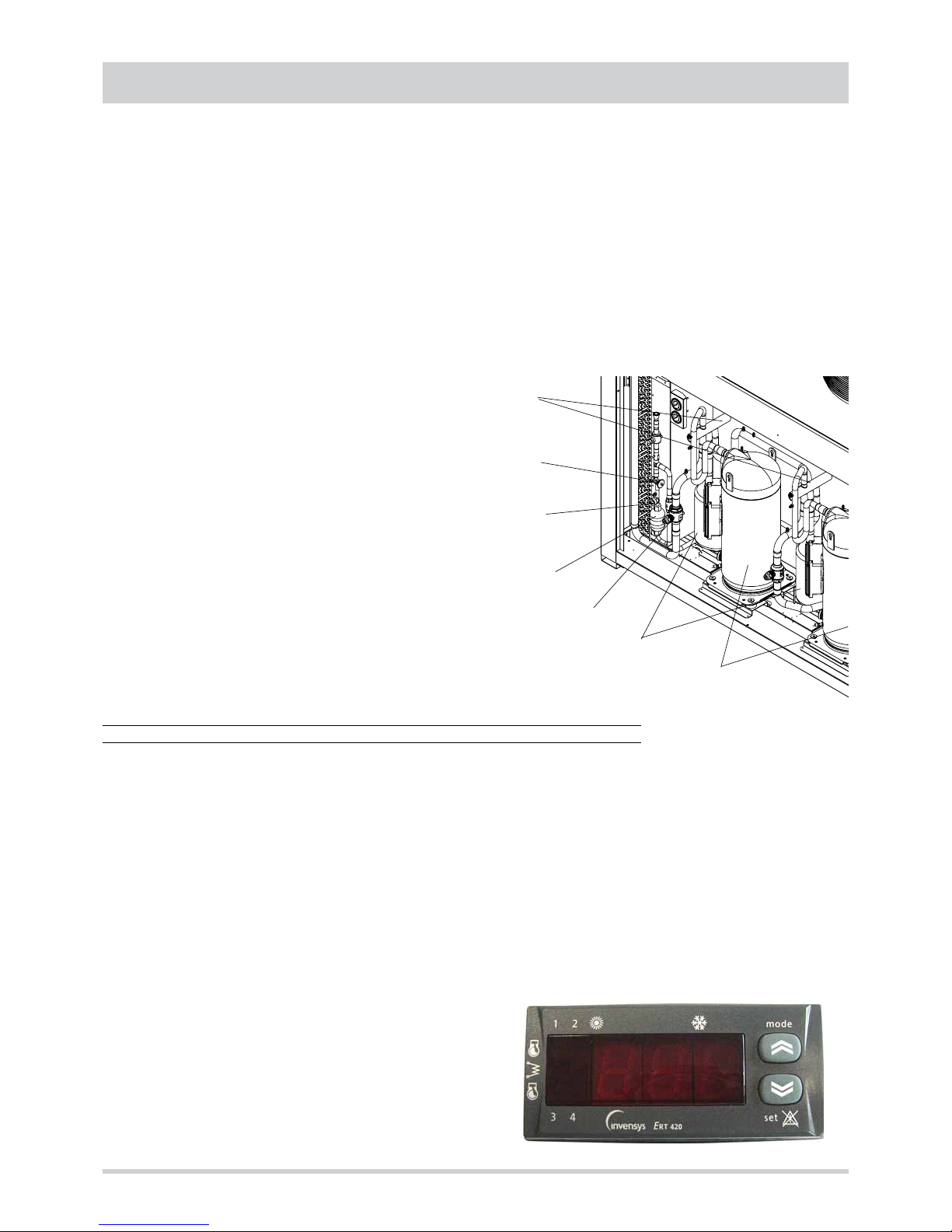
Refrigerant circuit. It is contained inside a compartment
separated from the air flow to simplify maintenance and control
operations.
The ermetic scroll compressors (1) are mounted on damper
supports and are protected against overtemperatures and
overcurrents. They are equipped with an electrical heater,
that is activated when the compressor turns off, to keep the
compressor crankcase oil temperature high enough to prevent
migration of refrigerant during winter stops and to evaporate
any liquid present in the crankcase, in order to prevent possible
liquid rushes on starting (only heat pump models).
Page 7
7
GENERAL FEATURES
The internal side heat exchanger (user side) (2) is a finned
coil realized with grooved copper pipes and aluminium fins
with notched profile to increase the heat exchange coefficient.
To avoid condensate drag, the frontal crossing air velocity
don't exceed 2,7 m/s, also with the maximum air flow rate
configuration and in the least favourable thermohygrometric
conditions. For the condensate drainage there is a stainless
steel drain tray with inclined bottom, equipped with threaded
connector for the discharge.
The external side heat exchanger (source side) (3) is a
finned coil realized with grooved copper pipes and aluminium
fins with notched profile.
The expansion device (4), a thermostatic expansion valve with
external equalizer , allow the unit to adjust itself to the different
operating conditions keeping steady the set superheating.
The presence in each refrigerant circuit of two valves (one
for the cooling mode and one for the heating mode) allow
to optimize the adjustment of each valve and to obtain the
maximum efficiency.
Each refrigerant circuit contains moreover solid core hermetic
filter dryer (5) to restrain impurity and moisture residuals that
could be present in the circuit, liquid separator (6) placed on
the inlet pipe to protect the compressor against liquid returns,
liquid and humidity indicator (7) to detect the presence of
liquid before each thermostatic valve and allow to verify the
presence of humidity inside the refrigerant, shut off valves
(8) upstream and downstream of each external coil to allow to
stock all the refrigerant inside the coils (pump down) and permit
to execute maintenance operations on the refrigerant circuit
without discharging it, high and low pressure switches in
order to assure the compressor to operate inside the permitted
limits, 4 way reverse cycle valve (9) to allow operating
mode change reversing the refrigerant flow (only heat pump
models) and pressure connections SAE 5/16” - UNF 1/2” 20 equipped with pin, gasket and blind nut, as required for the
use of R410A refrigerant (they allow the complete check of
the refrigerant circuit: compressor inlet pressure, compressor
outlet pressure and thermostatic valve upstream pressure).
Electrical panel. It contains all the power, control and security
components necessary to guarantee the unit to work properly.
The unit is managed by a microprocessor controller to which all
the electrical loads and the control devices are connected. The
user interface, accessible removing the protection panel of the
electrical board, allow to view and to modify, if necessary, all
the parameters of the unit.
All the units are supplied with an outdoor temperature sensor,
already installed on the unit.
Control system
The unit is managed by a microprocessor controller to which,
through a board placed inside the electrical panel, all the
electrical loads and the control devices are connected. The
user interface, accessible removing the protection panel of
the electrical board, is realized by a display and two buttons
that allow to view and, if necessary, modify all the operating
parameters of the unit.
Are available, as accessories, a remote control, that reports all
the functionalities of the user interface placed on the unit, or a
remote thermostat.
The main functions available are :
- treated air temperature management (through set point
adjustment)
- treated air humidity management (only with enthalpic free
cooling option)
- treated air quality management (CO
2
)
- thermal or enthalpic (option) free cooling
- external fan management by means of continuos rotational
speed control (option)
- internal fan management
- return air fan management
- integrative heating sources management (electrical heater
coil, hot water coil, gas heating module)
- defrost cycle management
- dampers management (outdoor air, return air and expulsion
air)
- compressor and internal fan operating hours recording
- serial communication through Modbus protocol
- remote on-off
- remote cooling-heating
- active alarms visualization
- general alarm digital output
6
8
5
4
7
9
3
1
Page 8

8
Constructive configurations
GENERAL FEATURES
Base version - VB
Each model can be supplied in different constructive
configurations in order to satisfy the application requirements
that can be necessary for the plants. The various versions,
obtained adding to the base version some modules, are always
supplied already assembled, wired and tested in the factory.
All the versions can be arranged with standard air flow position
(frontal for the models of frame 1 and 2 and upwards for the
models of frame 3) or with downwards air flow position.
The dotted components are accessories.
It only allows to operate with all return air.
It contains the standard filtering section and the airrefrigerant exchange coil that allows the heating, cooling and
dehumidification processes to be performed.
It is possible to add a further heating section (hot water coil or
electrical heater coil) and the droplets separator.
Instead of such heating section it is possible to add a gas
heating module, placed between the filtering section and the
air-refrigerant exchange coil.
1 damper version - V1
It allows to operate with a percentage of outdoor fresh air,
adjustable manually setting the damper placed on the adding
module. The outdoor air inlet is equipped with a rain protection
cap and a metal safety grille. The expulsion from the conditioned
ambient of an air flow rate equal to the outdoor fresh air flow
rate must be realized independently from the unit by means of
overpressure openings or other extraction devices.
In the adding module can be placed various type of special
filters in order to complete the standard filtering section.
Also in this version it is possible to add a further heating
section (hot water coil or electrical heater coil) and the droplets
separator.
Instead of such heating section it is possible to add a gas
heating module, placed between the filtering section and the
air-refrigerant exchange coil.
Downstream the internal fans, air flow silencers can be installed
to reduce the noise transmitted to the conditioned ambients
through the air ducts (only for the models of frame 1 and 2).
RETURN AIR AIR FLOW
AIR FLOWRETURN AIR
OUTDOOR AIR
Page 9

9
GENERAL FEATURES
2 dampers version - V2
The presence of two motorized dampers managed by the
controller of the unit allows to operate with a minimum
percentage of outdoor fresh air (adjustable through the user
interface) and to perform thermal free cooling.
The outdoor air inlet, equipped with a rain protection cap and
a metal safety grille, is designed for 100% of the total air flow
rate and allows to operate in free cooling with all outdoor air.
The expulsion from the conditioned ambient of an air flow
rate equal to the outdoor fresh air flow rate must be realized
independently from the unit by means of overpressure
openings or other extraction devices.
In the adding module can be placed various type of special
filters in order to complete the standard filtering section.
It is possible to add a further heating section (hot water coil
or electrical heater coil) and the droplets separator. Instead of
such heating section it is possible to add a gas heating module,
placed between the filtering section and the air-refrigerant
exchange coil.
It is also possible to perform enthalpic free cooling by means of
the installation of the humidity sensors.
Downstream the internal fans, air flow silencers can be installed
to reduce the noise transmitted to the conditioned ambients
through the air ducts (only for the models of frame 1 and 2).
3 dampers version - V3
The presence of three motorized dampers managed by
the controller of the unit allows to operate with a minimum
percentage of outdoor fresh air (adjustable through the user
interface), to perform thermal free cooling and to manage the
air expulsion.
The outdoor air inlet, equipped with a rain protection cap and
a metal safety grille, is designed for 100% of the total air flow
rate and allows to operate in free cooling with all outdoor air.
The expulsion from the conditioned ambient of an air flow rate
equal to the outdoor fresh air flow rate is realized through the
return air fan and the expulsion damper placed inside the unit.
In the adding module can be placed various type of special
filters in order to complete the standard filtering section.
Also in this version it is possible to add a further heating
section (hot water coil or electrical heater coil) and the droplets
separator. Instead of such heating section it is possible to add
a gas heating module, placed between the filtering section and
the air-refrigerant exchange coil.
It is also possible to perform enthalpic free cooling by means of
the installation of the humidity sensors.
Downstream the internal fans, air flow silencers can be installed
to reduce the noise transmitted to the conditioned ambients
through the air ducts (only for the models of frame 1 and 2).
RETURN AIR
EXPULSION AIR
AIR FLOW
AIR FLOW
RETURN AIR
OUTDOOR AIR
OUTDOOR AIR
Page 10

10
GENERAL FEATURES
Options
Constructive
configuration
VB - Base version It only allows to operate with all return air.
V1 - 1 damper version It allows to operate with a fixed percentage of outdoor fresh air, manually set.
V2 - 2 dampers version
It allows to operate with a variable percentage of outdoor fresh air, adjusted by
the unit controller according to free cooling and air quality control algorythms.
V3 - 3 dampers version
It allows to operate with a variable percentage of outdoor fresh air, adjusted by
the unit controller according to free cooling and air quality control algorythms.
Moreover it manages the expulsion of an air flow rate equal to the outdoor fresh
air flow rate.
Air flow
position
Standard
(frontal or upwards)
For the models of frame 1 and 2 the standard position is frontal while for the
models of frame 3 the standard position is upwards.
Downwards It is available for all the models and it allows a more compact installation.
Internal fan
Standard
In order to adjust the performances of the internal fan to the air flow rate and
available head values required, for each model are available three type of internal fan that are different for pulleys used, electrical motor installed power and in
some cases for the kind of fan used.
The pulley installed on the electrical motor is a variable diameter type pulley
and allows, within certain limits, to adjust the performance curve of the fan to
the characteristic curve of the plant.
Upsized
Reduced
Heating
integration
Hot water coil
2 or 3 rows
with pipes
It performs the heating function (as heat pump integration or replacement), the
post heating function (in cooling mode) and the ice protection function. It is
equipped with automatic air vent, drain valve, shut off ball valves at the inlet and
outlet, safety valve (6 bar) and stainless steel condensate tray.
The ball type motorized 3 way valve is managed by the unit controller according
to an on-off logic.
Hot water coil
2 or 3 rows
with 3 way valve
Electrical heater coil
standard or upsized
It performs the heating function (as heat pump integration or replacement), the
post heating function (in cooling mode) and the ice protection function. It is
equipped with safety thermostat and is protected against overcurrents by means of fuses placed inside the electrical panel.
Condensing
gas heating module
standard or upsized
It performs the heating function (as heat pump replacement) and the ice protection function. The stainless steel air-fumes exchanger is coupled with a mo-
dulating premixed burner that allows to adjust the power supplied inside a wide
operating range and to maximize the exploitation of the fumes condensing heat
also at part loads.
Low noise acoustic setting up
It allows to reduce the noise emissions produced by the unit through the insulation of the walls of the compartment that contains the refrigerant circuit and the
use of sound absorbent jackets on the compressors. Such setting up includes
also the modulating control of the external fans.
Air flow silencers
They allow to reduce the noise transmitted to the conditioned ambients through
the air ducts. They are realized by mineral wool acoustic baffles with fiberglass
coating placed downstream the centrifugal internal fan.
They are available only for the models of frame 1 and 2 with standard "Air flow
position" option.
External fans control
The modulating control of the external fans allows to operate with low outdoor
temperatures in cooling and high outdoor temperatures in heating and permits
to reduce noise emissions in such operating conditions.
The fans rotational speed is modulated continuosly by a phase cut device that
allow to control the condensing pressure (in cooling) and the evaporation pressure (in heating) according to the value read by the temperature probe placed
on the liquid line.
Page 11

11
GENERAL FEATURES
Accessories
Spring vibration dampers
Allow to reduce the transmission to the unit support plane of the mechanical vibrations generated by the compressor and by the fans in their normal operating mode.
In order to keep the insulation degree higher than 90%, the number and the features of the dampers are different
according to the model and the constructive configuration.
When this accessory is chosen, flexible connections must be used on all the aeraulic and hydraulic connections.
Moreover the height of the dampers, fitted between the basement of the unit and the support plane, must be
taken into account to design correctly the air ducts.
External coils
protection grilles
Protect the external surface of the finned coils.
High and low
pressure gauges
Each refrigerant circuit is equipped with two analog gauges, placed inside the refrigerant circuit compartment,
that detect the pressure in the compressor inlet and outlet pipes.
Remote control
It is suitable for wall mounting and reports all the functions available on the user interface normally placed on the
unit. It therefore allows the complete remote control of the unit.
Remote thermostat
It is suitable for wall mounting and consists of a simplified remote user interface compared to the standard one
normally placed on the unit. It allows to select the operating mode, set a deviation respect to the active set-point
and visualize the operating status and the presence of active alarms.
Modbus serial interface
on RS485
It allows to communicate with the unit controller and to view the operating conditions of the unit through Modbus
communication protocol. The RS485 serial line ensures the signal quality up to distances of about 1200 metres
(that can be extended by means of proper repeaters).
Programmer clock
It allows the unit to be turned on and off according to a set program, through the digital input available on the unit
wiring board (remote on-off).
Phase sequence and
voltage controller
It checks not only the presence and correct order of the power supply phases but also the voltage level on each
phase and avoid the unit to operate with voltage levels outside the permitted limits.
Roof curb
Metal structure to be applied to the units with downwards air flow in order to facilitate the installation and to
guarantee a perfect tight between the air duct and the unit itself.
The correct positioning of the roof curb requires an accurate finishing of the installation area.
Enthalpic free cooling
It allows to increase the seasonal efficiency of the unit through a more extended
and optimized use of the free cooling function, obtained considering the enthalpies of the outdoor and of the return air instead of the simple temperatures. The
measure of the relative humidity (of the outdoor and of the return air), necessary
for the enthalpy calculation, is realized through two capacitive humidity sensors.
Air quality control (CO
2
)
It manages the motorized dampers opening (in the versions in which they are
present) according to the CO
2
percentage of the ambients to be conditioned,
increasing, if necessary, the outdoor fresh air percentage.
If the (thermal or enthalpic) free cooling function is enabled the dampers opening is obtained by the combination of the two control logics.
Special filters
To complete the standard filtering section it is possible to add rigid pocket filters of various efficiency (from F6 to F9 according to EN 779) or active carbon
filters with F7 filtering class. The filter supporting frame is studied to guarantee
a perfect tight and an easy lateral extraction of the filters for the maintenance
operations.
Available only for the units with V1, V2 or V3 constructive configuration.
Filters differential pressure switch
It detects the pressure difference between upstream and downstream the filtering section. When the pressure drops exceed the maximum permitted value
(factory set according to the type of filters fitted on the unit) the pressure switch
stops the unit avoiding it to work with an air flow rate excessively low compared
to the one required.
Droplets separator
It is reccomended for units that require air flow rates particularly high compared
to the standard air flow rate and when the medium crossing air velocity is higher
than 2,7 m/s.
It avoids the condensate droplets that are generated on the exchange coil during cooling mode operation to be dragged. It is equipped with stainless steel
condensate tray with inclined bottom and threaded connector for the discharge.
It is never required if the hot water coil is mounted.
Page 12

12
TECHNICAL DATA AND PERFORMANCES
Frame
1 2 3
Model
35.1 45.1 55.1 70.2 90.2 110.2 140.2 180.2 220.2
U.M.
Powwer supply
400 - 3N - 50 400 - 3N - 50 400 - 3N - 50 V-ph-Hz
Technical data
Refrigerant
Type
R410A R410A R410A R410A R410A R410A R410A R410A R410A -
Compressor
Type
scroll scroll scroll scroll scroll scroll scroll scroll scroll -
Quantity
1 1 1 2 2 2 2 2 2 n°
Refrigerant circuits
1 1 1 2 2 2 2 2 2 n°
Power steps of the unit
0 - 100 0 - 100 0 - 100 0 - 50 - 100 0 - 50 - 100 0 - 50 - 100 0 - 50 - 100 0 - 50 - 100 0 - 50 - 100
%
Oil charge compressor 1
3,25 3,25 4,70 3,25 3,25 4,70 6,80 6,30 6,30 kg
Oil charge compressor 2
- - - 3,25 3,25 4,70 6,80 6,30 6,30 kg
Internal side heat exchanger (plant)
Type
finned
coil
finned
coil
finned
coil
finned
coil
finned
coil
finned
coil
finned
coil
finned
coil
finned
coil
-
Quantity
1 1 1 1 1 1 1 1 1 n°
Frontal surface
0,84 1,08 1,32 1,26 1,62 1,98 2,52 3,24 3,78 m
2
External side heat exchanger
Type
finned
coil
finned
coil
finned
coil
finned
coil
finned
coil
finned
coil
finned
coil
finned
coil
finned
coil
-
Quantity
1 1 1 2 2 2 2 2 2 n°
Frontal surface
1,96 1,96 1,96 1,96 1,96 1,96 4,00 4,00 4,00 m
2
External section fans
Type
axial axial
axial
axial
axial
axial
axial axial
axial -
Quantity
2 2 2 4 4 4 4 4 4 n°
Diameter
630 630 630 630 630 630 800 800 800 mm
Maximum rotational speed
900 900 900 900 900 900 900 900 900 rpm
Total installed power
1,6 1,6 1,6 3,2 3,2 3,2 8,0 8,0 8,0 kW
Internal section fans
Type
centrifugal centrifuga centrifuga centrifuga centrifuga centrifuga centrifuga centrifuga centrifuga
-
Quantity
2 2 2 2 2 2 2 2 2 n°
MINIMUM air flow rate
5200 6800 8400 9100 12100 14000 18500 23500 28500 m3/h
STANDARD air flow rate
6200 8100 10000 11000 14500 17000 22500 29000 35000 m3/h
MAXIMUM air flow rate
7200 9400 11700 13000 17000 20100 26500 34000 41000 m3/h
STANDARD available static head 200 200 200 200 200 200 200 200 200 Pa
Absorbed power
1,4 1,8 2,2 3,5 4,3 5,1 6,6 8,7 10,5 kW
Installed power
1,5 2,2 2,2 4,0 5,5 5,5 11,0 11,0 18,4 kW
Page 13

13
TECHNICAL DATA AND PERFORMANCES
NOMINAL performances
PC
Cooling A35A27 ( source : air in 35°C d.b. / plant : air in 27°C d.b. 19°C w.b. )
Total cooling capacity 35,5 46,3 57,7 71,0 92,3 113,0 142,0 184,0 226,0
kW
RST* 0,70 0,70 0,70 0,70 0,70 0,70 0,70 0,70 0,70
-
Power input 10,9 14,0 17,7 22,5 28,8 36,6 46,6 59,5 73,7
kW
EER 3,26 3,31 3,26 3,16 3,20 3,09 3,05 3,09 3,07
-
Air flow rate plant side 6200 8100 10000 11000 14500 17000 22500 29000 35000
m3/h
Available static head plant side 200 200 200 200 200 200 200 200 200
Pa
Heating A7A20 ( source : air in 7°C d.b. 6°C w.b. / plant : air in 20°C d.b. )
Heating capacity 36,7 47,8 59,5 73,9 95,9 118,0 148,0 192,0 236,0
kW
Power input 11,2 14,4 18,2 23,0 29,5 37,5 47,7 60,9 75,5
kW
COP 3,28 3,32 3,27 3,21 3,25 3,15 3,10 3,15 3,13
-
Air flow rate plant side 6200 8100 10000 11000 14500 17000 22500 29000 35000
m3/h
Available static head plant side 200 200 200 200 200 200 200 200 200
Pa
Data declared according to EN 14511. The values are referred to units without options and accessories operating with 100% return air.
* RST = ratio between sensible cooling capacity and total cooling capacity.
Frame
1 2 3
Model
35.1 45.1 55.1 70.2 90.2 110.2 140.2 180.2 220.2
U.M.
Power supply
400 - 3N - 50 400 - 3N - 50 400 - 3N - 50 V-ph-Hz
The graphs reported below allow to get the corrective factors to be applied to the performances with standard air flow rate in order
to obtain the real performances with the selected air flow rate.
0,85
0,90
0,95
1,00
1,05
1,10
1,15
0,80 0,85 0,90 0,95 1,00 1,05 1,10 1,15 1,20
COOLING OPERATING MODE
Performances with NOT STANDARD air flow rate
0,85
0,90
0,95
1,00
1,05
1,10
1,15
0,80 0,85 0,90 0, 95 1,00 1,05 1,10 1,15 1,20
HEATING OPERATING MODE
Heating capacity
Total cooling capacity
Power input
RST
Power input
Air flow rate / STANDARD air flow rate Air flow rate / STANDARD air flow rate
Page 14

14
0,4
0,6
0,8
1,0
1,2
1,4
1,6
1,8
2,0
15 20 25 30 35 40 45 50
0,5
0,6
0,7
0,8
0,9
1,0
1,1
1,2
1,3
1,4
1,5
15 20 25 30 35 40 45 50
0,5
0,6
0,7
0,8
0,9
1,0
1,1
1,2
1,3
1,4
1,5
15 20 25 30 35 40 45 50
TECHNICAL DATA AND PERFORMANCES
COOLING performances
The graphs allow to get the corrective factors to be applied to the
nominal performances in order to obtain the real performances in the
selected operating conditions.
The reference nominal condition is : A35A27
source : air in 35°C d.b. / plant : air in 27°C d.b. 19°C w.b.
Inlet w.b. temperature plant side :
Cooling capacity
Inlet air temperature d.b. [°C]
Inlet air temperature d.b. [°C]
Inlet air temperature d.b. [°C]
Power input
EER
A
B
C
D
A
B
C
D
A
B
C
D
0,5
0,6
0,7
0,8
0,9
1,0
1,1
1,2
1,3
1,4
1,5
15 20 25 30 35 40 45 50
RST
Inlet air temperature d.b. [°C]
A
B
C
D
A = 27°C
B = 23°C
C = 19°C
D = 15°C
E = 11°C
E
E
E
E
Page 15

15
TECHNICAL DATA AND PERFORMANCES
0,4
0,6
0,8
1,0
1,2
1,4
1,6
1,8
2,0
-15 -10 -5 0 5 10 15 20
0,5
0,6
0,7
0,8
0,9
1,0
1,1
1,2
1,3
1,4
1,5
-15 -10 -5 0 5 10 15 20
0,5
0,6
0,7
0,8
0,9
1,0
1,1
1,2
1,3
1,4
1,5
-15 -10 -5 0 5 10 15 20
HEATING performances
Heating capacity
Inlet air temperature w.b. [°C]
Inlet air temperature w.b. [°C]
Inlet air temperature w.b. [°C]
Power input
COP
A
B
C
D
A
B
C
D
A
B
C
DEE
E
The graphs allow to get the corrective factors to be applied to the
nominal performances in order to obtain the real performances in the
selected operating conditions.
The reference nominal condition is : A7A20
source : air in 7°C d.b. 6°C w.b. / plant : air in 20°C d.b.
Inlet d.b. temperature plant side :
A = 28°C
B = 24°C
C = 20°C
D = 16°C
E = 12°C
Page 16

16
TECHNICAL DATA AND PERFORMANCES
Hot water coil performances
2 ROWS
Water : 60 - 40 °C
Air flow rate
Minimum Standard Maximum
Model
T
inlet air
Capacity
Water
flow rate
Water
pressure
drops
Capacity
Water
flow rate
Water
pressure
drops
Capacity
Water
flow rate
Water
pressure
drops
[°C] [kW] [l/h] [kPa] [kW] [l/h] [kPa] [kW] [l/h] [kPa]
35.1
10 40,8 1771 4 45,7 1985 5 50,1 2176 6
15 33,3 1448 2 38,3 1664 4 42,7 1855 4
20 25,4 1102 1 29,4 1279 2 33,3 1448 2
45.1
10 52,7 2292 4 59,2 2571 5 64,8 2817 5
15 43,0 1869 2 49,4 2147 4 55,2 2400 4
20 32,6 1417 1 37,8 1644 2 42,8 1861 2
55.1
10 64,7 2812 4 72,7 3157 5 79,6 3457 5
15 52,7 2290 2 60,5 2631 4 67,8 2946 4
20 39,8 1731 1 46,2 2008 2 52,3 2274 2
70.2
10 70,8 3075 14 80,2 3484 18 88,8 3858 20
15 60,8 2641 11 68,8 2991 13 76,2 3309 16
20 50,8 2208 8 57,5 2498 10 63,6 2762 12
90.2
10 92,9 4038 14 104,5 4541 17 115,1 5003 20
15 79,8 3467 11 89,7 3896 13 98,7 4290 16
20 66,7 2898 8 74,9 3253 10 82,4 3579 11
110.2
10 110,2 4788 13 124,4 5404 16 137,4 5969 19
15 94,6 4111 10 106,7 4637 12 117,8 5118 14
20 79,1 3436 7 89,1 3871 8 98,3 4269 11
140.2
10 141,5 6150 14 160,4 6968 18 177,6 7716 20
15 121,5 5282 11 137,6 5982 13 152,3 6618 16
20 101,6 4416 8 115,0 4996 10 127,1 5524 12
180.2
10 185,9 8076 14 209,0 9082 17 230,3 10006 20
15 159,6 6934 11 179,3 7792 13 197,5 8580 16
20 133,4 5796 8 149,7 6506 10 164,7 7158 11
220.2
10 220,4 9576 13 248,7 10808 16 274,7 11938 19
15 189,2 8222 10 213,4 9274 12 235,6 10236 14
20 158,2 6872 7 178,2 7742 8 196,5 8538 11
2 ROWS
Water : 80 - 60 °C
Air flow rate
Minimum Standard Maximum
Model
T
inlet air
Capacity
Water
flow rate
Water
pressure
drops
Capacity
Water
flow rate
Water
pressure
drops
Capacity
Water
flow rate
Water
pressure
drops
[°C] [kW] [l/h] [kPa] [kW] [l/h] [kPa] [kW] [l/h] [kPa]
35.1
10 65,3 2867 8 73,1 3212 10 80,4 3532 12
15 59,2 2599 7 66,3 2912 8 72,9 3202 10
20 53,2 2335 6 59,5 2616 7 65,5 2875 8
45.1
10 84,7 3722 8 94,9 4167 10 104,2 4578 11
15 76,8 3374 6 86,0 3777 8 94,5 4150 10
20 69,0 3031 6 77,2 3392 7 84,8 3726 8
55.1
10 104,2 4577 7 116,6 5121 10 128,1 5625 11
15 94,5 4149 6 105,7 4642 8 116,1 5099 10
20 84,8 3727 5 94,9 4169 6 104,2 4578 7
70.2
10 110,7 4864 29 125,9 5531 36 139,8 6141 43
15 100,6 4419 24 114,4 5025 30 127,0 5579 36
20 90,6 3979 20 103,0 4524 25 114,3 5023 30
90.2
10 145,6 6396 29 164,3 7217 35 181,5 7972 42
15 132,3 5811 24 149,3 6556 30 164,9 7242 35
20 119,1 5231 20 134,4 5902 25 148,4 6518 30
110.2
10 172,6 7581 26 195,5 8587 32 216,5 9510 38
15 156,8 6887 22 177,6 7800 28 196,7 8638 32
20 141,2 6200 18 159,8 7021 23 177,0 7775 28
140.2
10 221,4 9728 29 251,8 11062 36 279,6 12282 43
15 201,2 8838 24 228,8 10050 30 254,0 11158 36
20 181,1 7958 20 206,0 9048 25 228,7 10046 30
180.2
10 291,2 12792 29 328,6 14434 35 363,0 15944 42
15 264,5 11622 24 298,5 13112 30 329,7 14484 35
20 238,2 10462 20 268,7 11804 25 296,8 13036 30
220.2
10 345,2 15162 26 390,9 17174 32 433,0 19020 38
15 313,6 13774 22 355,1 15600 28 393,3 17276 32
20 282,3 12400 18 319,7 14042 23 354,0 15550 28
Page 17

17
TECHNICAL DATA AND PERFORMANCES
3 ROWS
Water : 80 - 60 °C
Air flow rate
Minimum Standard Maximum
Model
T
inlet air
Capacity
Water
flow rate
Water
pressure
drops
Capacity
Water
flow rate
Water
pressure
drops
Capacity
Water
flow rate
Water
pressure
drops
[°C] [kW] [l/h] [kPa] [kW] [l/h] [kPa] [kW] [l/h] [kPa]
35.1
10 85,7 3765 19 97,7 4293 24 109,1 4791 30
15 77,8 3419 17 88,8 3899 20 99,1 4351 25
20 70,1 3080 13 79,9 3511 17 89,2 3918 20
45.1
10 111,5 4899 19 127,1 5581 24 141,7 6224 29
15 101,3 4449 16 115,4 5068 20 128,7 5652 24
20 91,2 4007 13 103,9 4564 17 115,8 5088 20
55.1
10 137,3 6032 19 156,4 6868 24 174,3 7656 29
15 124,7 5478 16 142,0 6237 19 158,3 6952 24
20 112,3 4934 13 127,8 5616 17 142,5 6259 20
70.2
10 146,0 6413 70 169,4 7440 90 191,2 8399 112
15 132,8 5833 59 154,0 6766 77 173,9 7638 95
20 119,8 5261 49 138,9 6102 64 156,8 6888 79
90.2
10 192,8 8468 70 221,6 9736 89 248,7 10924 109
15 175,3 7701 59 201,6 8854 76 226,1 9934 92
20 158,1 6945 49 181,8 7984 62 203,9 8957 77
110.2
10 227,5 9992 64 262,7 11538 82 295,6 12984 101
15 206,9 9087 54 238,9 10492 70 268,8 11807 85
20 186,6 8196 46 215,4 9462 58 242,4 10646 71
140.2
10 292,0 12826 70 338,7 14880 90 382,4 16798 112
15 265,6 11666 59 308,1 13532 77 347,8 15276 95
20 239,5 10522 49 277,8 12204 64 313,6 13776 79
180.2
10 385,5 16936 70 443,3 19472 89 497,3 21848 109
15 350,6 15402 59 403,1 17708 76 452,3 19868 92
20 316,2 13890 49 363,5 15968 62 407,8 17914 77
220.2
10 455,0 19984 64 525,3 23076 82 591,2 25968 101
15 413,7 18174 54 477,7 20984 70 537,6 23614 85
20 373,1 16392 46 430,8 18924 58 484,7 21292 71
3 ROWS
Water : 60 - 40 °C
Air flow rate
Minimum Standard Maximum
Model
T
inlet air
Capacity
Water
flow rate
Water
pressure
drops
Capacity
Water
flow rate
Water
pressure
drops
Capacity
Water
flow rate
Water
pressure
drops
[°C] [kW] [l/h] [kPa] [kW] [l/h] [kPa] [kW] [l/h] [kPa]
35.1
10 55,6 2417 10 63,2 2745 12 70,3 3054 14
15 47,9 2081 7 54,4 2362 10 60,4 2626 11
20 40,0 1737 6 45,6 1982 7 50,6 2201 8
45.1
10 72,3 3141 10 82,0 3564 12 91,2 3962 14
15 62,2 2705 7 70,6 3067 10 78,4 3407 11
20 51,9 2253 5 59,2 2572 7 65,7 2854 8
55.1
10 88,9 3865 10 100,9 4384 12 112,1 4871 14
15 76,6 3328 7 86,8 3771 8 96,4 4187 11
20 63,7 2769 5 72,8 3161 7 80,7 3506 8
70.2
10 95,8 4164 36 110,7 4812 47 124,6 5416 56
15 82,8 3599 28 95,7 4156 36 107,6 4675 44
20 69,9 3039 20 80,6 3504 26 90,6 3937 32
90.2
10 126,4 5491 36 144,8 6291 46 162,0 7038 55
15 109,2 4745 28 125,0 5432 35 139,8 6074 43
20 92,1 4004 20 105,4 4578 26 117,7 5114 31
110.2
10 149,2 6484 32 171,7 7458 42 192,6 8369 52
15 129,0 5603 25 148,2 6441 32 166,2 7223 40
20 108,8 4729 19 124,9 5429 24 140,0 6082 29
140.2
10 191,7 8328 36 221,5 9624 47 249,3 10832 56
15 165,7 7198 28 191,3 8312 36 215,2 9350 44
20 139,8 6078 20 161,3 7008 26 181,2 7874 32
180.2
10 252,7 10982 36 289,5 12582 46 323,9 14076 55
15 218,4 9490 28 250,0 10864 35 279,6 12148 43
20 184,3 8008 20 210,7 9156 26 235,4 10228 31
220.2
10 298,4 12968 32 343,3 14916 42 385,2 16738 52
15 257,9 11206 25 296,5 12882 32 332,4 14446 40
20 217,7 9458 19 249,9 10858 24 279,9 12164 29
Page 18

18
0
50
100
150
200
250
300
350
400
450
500
550
600
5000 6000 7000 8000 9000 10000 11000 12000
TECHNICAL DATA AND PERFORMANCES
Plant side aeraulic performances
Available static head - unit without options
The graphs are referred to units operating with air at the temperature of 20°C (density 1,20 kg/m
3
).
Air flow rate [ m
3
/h ]
Available static head [ Pa ]
Upsized
35.1
Standard
Reduced
The internal fan must be selected according to the required air ow rate and to the required total head.
The required total head must be calculated as sum of the required available head and of the pressure drops of the options or
accessories applied to the unit. Such pressure drops must be calculated according to the required air ow rate using the graphs
reported in the present manual.
The graphs reported below show the characteristic aeraulic curves of each model. Such curves are obtained subtracting to the
head supplied by the fan the pressure drops of the standard lters (G4), the pressure drops of the internal coil and the pressure
drops of the internal structure of the unit.
N.B. The curves are referred to units with BASE constructive conguration (VB) without options or accessories and with
dry internal coil.
Model
35.1 - 45.1 - 55.1 70.2 - 90.2 - 110.2 140.2 - 180.2 - 220.2
U.M.
Standard Upsized Standard Upsized Standard Upsized
Nominal heating capacity
max 44,8 54,0 93,4 145,0 186,8 290,0 kW
min 15,5 16,3 31,5 46,3 63,0 92,6 kW
Efciency
max 94,3 93,1 95,3 93,5 95,3 93,5 %
min 105,0 105,0 105,0 105,2 105,0 105,2 %
Gas input
(15°C – 1013 mbar)
max 5,03 6,14 10,37 16,40 20,74 32,8 m
3
/h
min 1,57 1,64 3,17 4,66 6,34 9,32 m
3
/h
Condensate generated 1,45 1,45 2,60 3,87 5,20 7,74 l/h
Available static head exhaust fumes 120 120 120 100 120 100 Pa
Model 35.1 - 45.1 - 55.1 70.2 - 90.2 - 110.2 140.2 - 180.2 - 220.2 U.M.
Standard coil 9,0 18,0 36,0 kW
Upsized coil 18,0 31,5 63,0 kW
The reported data are referred to the module operating with natural gas G20 at 20 mbar supply pressure.
Electrical heater coil performances
Condensing gas heating module performances
Page 19
19
0
50
100
150
200
250
300
350
400
450
500
550
600
5000 6000 7000 8000 9000 10000 11000 12000
TECHNICAL DATA AND PERFORMANCES
Air flow rate [ m3/h ]
Available static head [ Pa ]
Upsized
55.1
Standard
Reduced
The graphs are referred to units operating with air at the temperature of 20°C (density 1,20 kg/m
3
).
0
50
100
150
200
250
300
350
400
450
500
550
600
5000 6000 7000 8000 9000 10000 11000 12000
Air flow rate [ m3/h ]
Available static head [ Pa ]
Upsized
45.1
Standard
Reduced
Page 20

20
0
50
100
150
200
250
300
350
400
450
500
550
600
8000 9000 10000 11000 12000 13000 14000 15000 16000 17000 18000 19000 20000 21000
Air flow rate [ m3/h ]
Available static head [ Pa ]
Upsized
70.2
Standard
Reduced
0
50
100
150
200
250
300
350
400
450
500
550
600
8000 9000 10000 11000 12000 13000 14000 15000 16000 17000 18000 19000 20000 21000
TECHNICAL DATA AND PERFORMANCES
Air flow rate [ m3/h ]
Available static head [ Pa ]
Upsized
90.2
Standard
Reduced
The graphs are referred to units operating with air at the temperature of 20°C (density 1,20 kg/m
3
).
Page 21

21
0
50
100
150
200
250
300
350
400
450
500
550
600
650
700
750
800
850
900
16000 18000 20000 22000 24000 26000 28000 30000 32000 34000 36000 38000 40000 42000
TECHNICAL DATA AND PERFORMANCES
Air flow rate [ m3/h ]
Available static head [ Pa ]
Upsized
140.2
Standard
Reduced
The graphs are referred to units operating with air at the temperature of 20°C (density 1,20 kg/m
3
).
0
50
100
150
200
250
300
350
400
450
500
550
600
8000 9000 10000 11000 12000 13000 14000 15000 16000 17000 18000 19000 20000 21000
Air flow rate [ m3/h ]
Available static head [ Pa ]
Upsized
110.2
Standard
Reduced
Page 22

22
0
50
100
150
200
250
300
350
400
450
500
550
600
650
700
750
800
850
900
16000 18000 20000 22000 24000 26000 28000 30000 32000 34000 36000 38000 40000 42000
Air flow rate [ m3/h ]
Available static head [ Pa ]
Upsized
180.2
Standard
Reduced
0
50
100
150
200
250
300
350
400
450
500
550
600
650
700
750
800
850
900
16000 18000 20000 22000 24000 26000 28000 30000 32000 34000 36000 38000 40000 42000
TECHNICAL DATA AND PERFORMANCES
Air flow rate [ m3/h ]
Available static head [ Pa ]
Upsized
220.2
Standard
Reduced
The graphs are referred to units operating with air at the temperature of 20°C (density 1,20 kg/m
3
).
Page 23

23
TECHNICAL DATA AND PERFORMANCES
The graphs are referred to units operating with air at the temperature of 20°C (density 1,20 kg/m3).
Available static head of the return air fan
When the return air fan is present, verify that the available head, corresponding to an air ow rate equal to the 70% of the air ow
rate dened for the internal fan, is not higher than the pressure drops in the return duct.
If necessary modify the fan speed in order to reduce the available head.
In such way it is possible to guarantee a correct air extraction, keeping a little over pressure in the room to be conditioned also
when the unit is working with all external air.
Air flow rate [ m
3
/h ]
Available static head [ Pa ]
0
50
100
150
200
250
300
350
400
450
500
4000 8000 12000 16000 20000 24000 28000 32000 36000 40000
35.1
45.1
55.1
70.2
90.2
110.2
140.2
180.2
220.2
0
10
20
30
40
5000 10000 15000 20000 25000 30000 35000 40000
Pressure drops to be added due to condensate generation on the internal coil
Air flow rate [ m
3
/h ]
Pressure drops [ Pa ]
35.1 45.1 55.1 70.2 90.2 110.2 140.2 180.2 220.2
Page 24

24
0
30
60
90
120
150
180
5000 6000 7000 8000 9000 10000 11000 12000
Pressure drops - unit with option “Special filters”
Air flow rate [ m
3
/h ]
Pressure drops [ Pa ]
TECHNICAL DATA AND PERFORMANCES
4
5
3
2
1
0
35.1
45.1
55.1
The graphs are referred to units operating with air at the temperature of 20°C (density 1,20 kg/m3).
Type of filter
Efficiency
EN 779
Medium efficiency
Em [%]
(on 0,4 µm parts)
Eurovent
classification
0 STANDARD waved filter G 4 - EU 4
1 Rigid pocket filter F 6 60 ≤ Em < 80 EU 6
2 Rigid pocket filter F 7 80 ≤ Em < 90 EU 7
3 Rigid pocket filter F 8 90 ≤ Em < 95 EU 8
4 Rigid pocket filter F 9 95 ≤ Em EU 9
5
Rigid pocket filter
with active carbons
F 7 80 ≤ Em < 90 EU 7
Page 25

25
TECHNICAL DATA AND PERFORMANCES
The graphs are referred to units operating with air at the temperature of 20°C (density 1,20 kg/m3).
0
30
60
90
120
150
180
18000 20000 22000 24000 26000 28000 30000 32000 34000 36000 38000 40000 42000
Air flow rate [ m3/h ]
Pressure drops [ Pa ]
4
5
3
2
1
0
140.2
180.2
220.2
0
30
60
90
120
150
180
9000 10000 11000 12000 13000 14000 15000 16000 17000 18000 19000 20000
Air flow rate [ m3/h ]
Pressure drops [ Pa ]
4
5
3
2
1
0
70.2
90.2
110.2
Page 26

26
TECHNICAL DATA AND PERFORMANCES
0
20
40
60
80
100
5000 10000 15000 20000 25000 30000 35000 40000
Pressure drops - unit with option “Heating integration” : "Hot water coil"
Air flow rate [ m
3
/h ]
Pressure drops [ Pa ]
0
20
40
60
80
100
120
5000 10000 15000 20000 25000 30000 35000 40000
Pressure drops - unit with option “Heating integration” : "Condensing gas heating module"
Air flow rate [ m
3
/h ]
Pressure drops [ Pa ]
The graphs are referred to units operating with air at the temperature of 20°C (density 1,20 kg/m3).
35.1 - 3R 45.1 - 3R 55.1 - 3R 70.2 - 3R 90.2 - 3R 110.2 - 3R 140.2 - 3R 180.2 - 3R 220.2 - 3R
35.1 - 2R 45.1 - 2R 55.1 - 2R 70.2 - 2R 90.2 - 2R 140.2 - 2R 180.2 - 2R 220.2 - 2R110.2 - 2R
70.2
90.2
110.2
35.1
45.1
55.1
140.2
180.2
220.2
Standard
and upsized
Standard
Upsized
Standard
Upsized
Page 27

27
TECHNICAL DATA AND PERFORMANCES
0
5
10
15
20
25
5000 10000 15000 20000 25000 30000 35000 40000
Pressure drops - unit with option “Heating integration” : "Electricl heater coil"
Air flow rate [ m
3
/h ]
Pressure drops [ Pa ]
0
10
20
30
40
50
5000 10000 15000 20000 25000 30000 35000 40000
Pressure drops - unit with option “Droplets separator”
Air flow rate [ m
3
/h ]
Pressure drops [ Pa ]
The graphs are referred to units operating with air at the temperature of 20°C (density 1,20 kg/m3).
70.2
90.2
110.2
35.1
45.1
55.1
140.2
180.2
220.2
Standard
Upsized
Standard
Upsized
Upsized
Standard
70.2
90.2
110.2
35.1
45.1
55.1
140.2
180.2
220.2
Page 28

28
TECHNICAL DATA AND PERFORMANCES
0
20
40
60
80
100
120
140
160
5000 7000 9000 11000 13000 15000 17000 19000 21000
Pressure drops - unit with option “Air flow silencers”
Air flow rate [ m
3
/h ]
Pressure drops [ Pa ]
The graphs are referred to units operating with air at the temperature of 20°C (density 1,20 kg/m3).
70.2
90.2
110.2
35.1
45.1
55.1
Page 29

29
TECHNICAL DATA AND PERFORMANCES
Operating limits
The graphs reported below show the operating area inside which the correct working of the unit is guaranteed.
10
15
20
25
30
35
40
5 10 15 20 25 30 35 40 45 50 55
COOLING
Inlet air temperature d.b - source side [°C]
Inlet air temperature d.b. - plant side [°C]
0
5
10
15
20
25
30
-15 -10 -5 0 5 10 15 20 25
HEATING
Inlet air temperature d.b - source side [°C]
Inlet air temperature d.b. - plant side [°C]
The limits are approximate and are referred to STANDARD air flow rate.
Page 30

30
TECHNICAL DATA AND PERFORMANCES
Electrical data
Model 35.1 45.1 55.1 70.2 90.2 110.2 140.2 180.2 220.2 U.M.
Power supply 400V - 3ph+N - 50Hz V-ph-Hz
F.L.A. - Maximum current input
Compressor 1 23,0 28,0 37,0 23,0 28,0 37,0 45,0 60,0 76,0 A
Compressor 2 - - - 23,0 28,0 37,0 45,0 60,0 76,0 A
Single external fan 3,5 3,5 3,5 3,5 3,5 3,5 4,3 4,3 4,3 A
Internal fan
reduced 2,7 3,6 4,2 6,4 6,4 8,6 17,1 22,9 30,4 A
standard 3,6 4,2 4,9 8,6 11,4 11,4 22,9 22,9 35,6 A
upsized 4,9 6,4 6,4 11,4 17,1 17,1 30,4 35,6 35,6 A
Return air fan 3,5 3,5 3,5 7,0 7,0 7,0 17,1 17,1 17,1 A
Electrical heater coil
standard 13,0 13,0 13,0 26,0 26,0 26,0 52,0 52,0 52,0 A
upsized 26,0 26,0 26,0 45,5 45,5 45,5 90,9 90,9 90,9 A
F.L.I. - Maximum power input
Compressor 1 13,4 16,9 22,6 13,4 16,9 22,6 27,4 36,6 46,3 kW
Compressor 2 - - - 13,4 16,9 22,6 27,4 36,6 46,3 kW
Single external fan 0,8 0,8 0,8 0,8 0,8 0,8 2,0 2,0 2,0 kW
Internal fan
reduced 1,4 1,9 2,3 3,6 3,6 4,8 9,5 12,8 17,1 kW
standard 1,9 2,3 2,7 4,8 6,4 6,4 12,8 12,8 20,5 kW
upsized 2,7 3,6 3,6 6,4 9,5 9,5 17,1 20,5 20,5 kW
Return air fan 1,1 1,1 1,1 2,2 2,2 2,2 9,5 9,5 9,5 A
Electrical heater coil
standard 9,0 9,0 9,0 18,0 18,0 18,0 36,0 36,0 36,0 kW
upsized 18,0 18,0 18,0 31,5 31,5 31,5 63,0 63,0 63,0 kW
L.R.A. - Start current
Compressor 1 118,0 198,0 225,0 118,0 198,0 225,0 272,0 310,0 394,0 A
Compressor 2 - - - 118,0 198,0 225,0 272,0 310,0 394,0 A
Single external fan 7,5 7,5 7,5 7,5 7,5 7,5 11,0 11,0 11,0 A
Internal fan
reduced 11,1 16,6 20,2 33,3 33,3 33,7 67,4 99,0 143,5 A
standard 16,6 20,2 25,0 33,7 49,5 49,5 99,0 99,0 184,4 A
upsized 25,0 33,3 33,3 49,5 67,4 67,4 143,5 184,4 184,4 A
Return air fan 5,5 5,5 5,5 11,0 11,0 11,0 67,4 67,4 67,4 A
TOTAL *
F.L.A. - Maximum total current input 34 39 49 69 81 99 130 160 205 A
F.L.I. - Maximum total power input 17 21 27 35 43 55 76 94 121 kW
M.I.C. - Maximum total start current 129 209 237 164 251 287 357 410 523 A
* BASE version with STANDARD internal fan and without accessories.
Page 31

31
TECHNICAL DATA AND PERFORMANCES
Noise levels
BASE acoustic setting up (AB)
Model
Sound power levels [dB]
by octave bands [Hz]
Sound power
level
Sound pressure level
at 1 metre at 5 metres at 10 metres
63 125 250 500 1000 2000 4000 8000 [dB] [dB(A)] [dB(A)] [dB(A)] [dB(A)]
35.1 83,6 82,7 84,7 79,9 80,6 76,5 69,7 62,4 90 84 67 58 53
45.1 86,6 83,4 85,2 80,4 80,9 76,9 70,6 63,4 91 85 67 58 53
55.1 88,2 84,2 85,7 81,0 81,2 77,4 71,6 64,3 92 85 68 59 54
70.2 86,2 85,4 87,6 82,7 83,5 79,3 72,3 65,2 93 87 69 60 55
90.2 89,0 85,8 87,8 83,0 83,5 79,4 73,0 65,9 94 87 69 61 56
110.2 91,0 86,7 88,5 83,8 84,0 80,2 74,1 67,0 95 88 70 61 56
140.2 93,2 88,9 90,7 86,0 86,2 82,4 76,3 69,2 97 90 71 63 58
180.2 95,2 90,9 92,7 88,0 88,2 84,4 78,3 71,2 99 92 73 65 60
220.2 96,2 91,9 93,7 89,0 89,2 85,4 79,3 72,2 100 93 74 66 61
Model
Sound power levels [dB] by octave bands [Hz]
Sound power
level
63 125 250 500 1000 2000 4000 8000 [dB] [dB(A)]
35.1 84,4 82,8 83,0 76,2 76,0 75,1 72,0 65,9 89 82
45.1 84,5 82,7 83,6 78,1 78,4 78,3 76,0 70,9 90 85
55.1 86,6 83,4 85,5 80,2 81,1 81,0 79,4 75,1 92 87
70.2 84,9 86,4 80,7 78,6 75,2 75,3 73,2 67,4 90 82
90.2 83,8 86,7 82,8 82,5 78,7 78,7 76,9 71,5 91 86
110.2 84,3 88,4 84,2 85,2 80,7 80,9 79,5 74,7 93 88
140.2 75,0 73,0 72,0 74,0 74,0 72,0 70,0 65,0 82 79
180.2 79,0 77,0 76,0 78,0 78,0 76,0 74,0 69,0 86 83
220.2 83,0 81,0 80,0 82,0 82,0 80,0 78,0 73,0 90 87
Unit noise levels
Internal fan noise levels
Reference conditions
Performances referred to units with VB constructive configuration (base version) operating in cooling mode at NOMINAL conditions A35A27 with
STANDARD air flow rate and available static head.
Unit placed in free field on reflecting surface (directional factor equal to 2) with air inlet and outlet connections ducted for 2 metres.
The sound power level is measured according to ISO 3744 standard.
The sound pressure level is calculated according to ISO 3744 and is referred to a distance of 1/5/10 metres from the external surface of the unit.
LOW NOISE acoustic setting up (AS)
Model
Sound power levels [dB]
by octave bands [Hz]
Sound power
level
Sound pressure level
at 1 metre at 5 metres at 10 metres
63 125 250 500 1000 2000 4000 8000 [dB] [dB(A)] [dB(A)] [dB(A)] [dB(A)]
35.1 77,2 78,1 80,8 76,5 77,7 74,1 67,6 60,5 86 81 64 55 50
45.1 80,3 78,9 81,4 77,1 78,1 74,6 68,6 61,6 87 82 64 55 50
55.1 81,9 79,7 81,9 77,7 78,4 75,1 69,6 62,5 88 82 65 56 51
70.2 79,9 80,9 83,8 79,4 80,7 77,0 70,3 63,4 89 84 66 58 53
90.2 82,6 81,2 83,9 79,6 80,6 77,0 70,9 64,0 89 84 66 58 53
110.2 84,9 82,4 84,9 80,7 81,4 78,1 72,3 65,4 91 85 67 59 54
140.2 86,9 84,4 86,9 82,7 83,4 80,1 74,3 67,4 93 87 68 60 55
180.2 88,9 86,4 88,9 84,7 85,4 82,1 76,3 69,4 95 89 70 62 57
220.2 89,9 87,4 89,9 85,7 86,4 83,1 77,3 70,4 96 90 71 63 58
Reference conditions
Performances referred to units with VB constructive configuration (base version) operating in cooling mode at NOMINAL conditions A35A27 with
STANDARD air flow rate and available static head.
The sound power level is obtained starting from the data declared by the manufacturer of the fans.
Page 32

32
TECHNICAL DATA AND PERFORMANCES
Weights
Model 35.1 45.1 55.1 70.2 90.2 110.2 140.2 180.2 220.2 U.M.
Constructive configuration
Base version VB 724 807 874 1052 1220 1345 1820 1940 2010 kg
1 damper version V1 916 999 1066 1316 1484 1609 2148 2268 2338 kg
2 dampers version V2 927 1010 1077 1327 1495 1620 2170 2290 2360 kg
3 dampers version V3 1130 1213 1280 1577 1745 1870 2810 2930 3000 kg
Options and accessories
Internal fan
Reduced -3 -6 -2 -6 -17 -11 -22 0 -12 kg
Upsized 9 7 7 11 49 49 20 32 0 kg
Hot water coil
2 rows with pipes 31 35 38 39 44 49 70 80 90 kg
2 rows with 3 way valve 36 40 43 47 52 57 82 92 102 kg
3 rows with pipes 36 41 46 46 53 61 84 98 114 kg
3 rows with 3 way valve 41 46 51 54 61 69 96 110 126 kg
Electrical heater coil
Standard 21 21 21 37 37 37 74 74 74 kg
Upsized 34 34 34 52 52 52 104 104 104 kg
Condensing
gas heating module
Standard 270 270 270 402 402 402 720 720 720 kg
Upsized 275 275 275 442 442 442 800 800 800 kg
External coils protection grilles 8 8 8 16 16 16 32 32 32 kg
Droplets separator 29 29 29 41 41 41 78 78 78 kg
Rigid pocket filters 21 21 21 31 31 31 62 62 62 kg
Air flow silencers 27 27 27 36 36 36 - - - kg
The total weight of the unit, obtained summing up the weight of the unit in the chosen constructive configuration with the weight of
the selected accessories, is referred to the transport weight.
The weight of the accessories not present in the table reported above is negligible for the estimate of the total weight of the unit.
Model
Acoustic attenuation [dB] by octave bands [Hz]
63 125 250 500 1000 2000 4000 8000
35.1-45.1-55.1 3,0 4,0 16,0 19,0 25,0 24,0 16,0 12,0
70.2-90.2-110.2 3,0 2,0 15,0 14,0 16,0 18,0 13,0 9,0
Model
Sound power levels [dB] by octave bands [Hz]
Sound power
level
63 125 250 500 1000 2000 4000 8000 [dB] [dB(A)]
35.1 65,6 69,7 65,5 66,5 62,0 62,2 60,8 56,0 74 69
45.1 67,6 71,7 67,5 68,5 64,0 64,2 62,8 58,0 76 71
55.1 69,6 73,7 69,5 70,5 66,0 66,2 64,8 60,0 78 73
70.2 68,6 72,7 68,5 69,5 65,0 65,2 63,8 59,0 77 72
90.2 70,6 74,7 70,5 71,5 67,0 67,2 65,8 61,0 79 74
110.2 72,6 76,7 72,5 73,5 69,0 69,2 67,8 63,0 81 76
140.2 75,0 76,3 75,4 75,6 74,0 73,8 72,5 67,1 83 80
180.2 80,0 81,3 80,4 80,6 79,0 78,8 77,5 72,1 88 85
220.2 84,0 85,3 84,4 84,6 83,0 82,8 81,5 76,1 92 89
Return air fan noise levels
Air flow silencers acoustic attenuation
Reference conditions
Performances referred to units with V3 constructive configuration (3 dampers version) operating in cooling mode at NOMINAL conditions A35A27
with STANDARD air flow rate and available static head.
The sound power level is obtained starting from the data declared by the manufacturer of the fans.
Page 33

33
D
6
7
10
6
5551
150
2251
Q.E.
5
4
3
245 285
9
8
11
A2
Q.E.
245
5
4
3
13
11
6
7
10
9
8
E
5551
2251
D M 150
H
A4 N
6
106 B 106
39
39
5
53 A1 5 3
6
6
C
1
2
5
2
1
C
39
39
1
53 A1 53
106 B 106
6
6
35.1
45.1
55.1
70.2
90.2
110.2
VB
VB
con modulo
termico a gas
LEGEND
POS. DESCRIPTION
1 Refrigerant circuit inspection panel
2 Electrical box inspection panel
3 Internal fan inspection panel
4 External coils
5 External fans
6 Lifting points
7 Power supply holes
8 Internal coils condensate drain
9 Internal section condensate drain
10 External section condensate drain
11 Standard filters frame
12 External air cap
13 Gas heating module
14 Module for V1 and V2 constructive configurations
15 Module for V3 constructive configuration
35.1 - 45.1 - 55.1 70.2 - 90.2 - 110.2 UM
A1 1294 1894 mm
A2 2205 2370 mm
A3 2900 3065 mm
A4 2955 3255 mm
A5 3830 4265 mm
B 1188 1788 mm
C 1400 2000 mm
D 2735 2900 mm
E 2885 3050 mm
F 3535 3700 mm
G 4335 4500 mm
H 3815 4250 mm
I 4465 4900 mm
L 5265 5700 mm
M 930 1200 mm
N 465 600 mm
O 1265 1400 mm
VB
VB
with
condensing gas
heating module
A = Spring vibration dampers holes distance
TECHNICAL DATA AND PERFORMANCES
Overall dimensions
Models 35.1 - 45.1 - 55.1 - 70.2 - 90.2 - 110.2
Page 34

34
Q.E.
3
14
13
4
7
10
6
9
8
12
12
5
2251
5551
245 A4
I
O
D M 8 00 468
Q.E.
D
4
3
5
245 A2
7
10
9
8
6
6
14
5551
2251
12
12
F
800 468
1085
Q.E.
3
15
13
4
7
10
6
9
8
12
12
5
2251
245 A5 1190
L
6
5551
D M 1600 468
Q.E.
D
4
3
5
245
7
10
9
8
6
15
2251
12
12
A3 1190
1600 468
G
6
5551
6
V3
con
modulo
termico
a gas
V3
V1 – V2
con modulo
termico a gas
V1 – V2
V1 - V2
TECHNICAL DATA AND PERFORMANCES
V1 - V2
with
condensing gas
heating module
V3
V3
with
condensing gas
heating module
Page 35

35
6
10
6
8
3
3
11
2
1
1
6
6
5
9
5
7
4
4
212,5
2345
2132,5
2200
55 A1 55
39
39
106 B 106
2132
2345
365 A2 285
D 150
E
6
10
8
3
3
11
9
5
7
6
13
13
4
4
2132
365
2345
A4 N
D M 150
H
VB CON MODULO TERMICO A GAS
6
10
8
3
3
9
5
7
6
13
13
6
10
8
3
3
12
9
5
7
6
14
12
12
12
4
4
4
4
12
12
12
12
14
2132
365
2132
800 468
2345
2345
365 1085
800 468
V1 - V2 CON MODULO TERMICO A GAS
V1 - V2
3935
1400
3700
1200
5700
3050
3700
4500
VB
VB
with
condensing gas
heating module
V1 - V2
V1 - V2
with
condensing gas
heating module
LEGEND
POS. DESCRIPTION
1 Refrigerant circuit inspection panel
2 Electrical box inspection panel
3 Internal fan inspection panel
4 External coils
5 External fans
6 Lifting points
7 Power supply holes
8 Internal coils condensate drain
9 Internal section condensate drain
10 External section condensate drain
11 Standard filters frame
12 External air cap
13 Gas heating module
14 Module for V1 and V2 constructive configurations
15 Module for V3 constructive configuration
A = Spring vibration dampers holes distance
Models 140.2 - 180.2 - 220.2
TECHNICAL DATA AND PERFORMANCES
Page 36

36
8
17
16
1
2
9
3
5
10
11
7
4
B
C
A
B
A
C
8
17
16
1
2
9
3
10
11
7
4
5
1
The choice of the location of the unit is very important in order to guarantee the unit to work properly. Air flow obstructions, air
circulation difficulties, leaves or other foreign materials that can clog the coils, winds that blow against or excessively favour the
air flow, air stratification or ricirculation effects, nearby heat sources, are all causes of anomalous operating or shut downs of the
unit caused by :
• in cooling mode : condensing pressure increase with performances loss and possible high pressure alarms;
• in heating mode : evaporation pressure decrease with increased number of defrosting cycles and consequent performances loss
and possible low pressure alarms.
For this reason, placement under the ground level or near very high walls must be evaluated very carefully. If the heat pump operates at temperatures below freezing for extended periods of time, it is important to facilitate the discharge of the water produced
by the defrosting operations to prevent the buildup of ice near the bottom of the machine. During winter operation the heat pump
generates a considerable amount of condensate; make sure that this does not cause any problems to people or property.
On the upper side there must not be any obstruction to the air discharge.
On the inlet and outlet sides guarantee enough space for ducts maintenance.
Respect the free area around the unit as shown in the figure in order to guarantee a good accessibility and facilitate maintenance
and control operations.
TECHNICAL DATA AND PERFORMANCES
LEGEND
POS. DESCRIPTION
1 Refrigerant circuit inspection panel
2 Electrical box inspection panel
3 Internal fan inspection panel
4 External coils
5 External fans
7 Power supply holes
8 Internal coils condensate drain
9 Internal section condensate drain
10 External section condensate drain
11 Standard filters frame
16 Return air duct
17 Flow duct
35.1 - 45.1 - 55.1 70.2 - 90.2 - 110.2 - 140.2 - 180.2 - 220.2 UM
A 1000 1500 mm
B 1500 1500 mm
C 1000 1000 mm
Minimum operating area
Page 37

37
CONNECTIONS
Hydraulic connections
Internal coil condensate discharge connection (compulsory)
It is very important that this operation be performed with particular care by specialized personnel. For the sequence follow these
instructions:
• . Connect the condensate discharge tube.
• . Use a siphon to eliminate the negative pressure created by the fan, thereby preventing the intake of gas by the discharge tube
and ensuring the regular discharge of the condensate.
• . Connect the opening to a drain pipe discharge network. Do not use white water or sewage drains so as to prevent the intake
of odors in case of water evaporation.
• . After the first hours of operation in the cooling mode, check that the siphon is effective.
1. Condensate collection drain pan inside the unit is constructed of stainless steel and has
been opportunely inclined to facilitate drainage.
2. External surface of the longitudinal member for the base.
3. Opening attached to the longitudinal member.
4. Example of a siphon made with PVC components, including a cap for cleaning (under
the responsibility of the user).
IMPORTANT:
• . Place the discharge tube so as not to cause mechanical stress on the unit’s discharge connector.
• . When the accessories for the water coil for post-heating only and the droplet separator are present, repeat the instructions
listed above also for the second discharge outlet.
• . See the drawings below for the position and dimensions of the connectors.
External coil condensate discharge connection (optional)
The drainage of the external coil is guaranteed by a drain pan equipped with a connector.
This discharge outlet (one for each external coil) was included to make it possible to convey the external coil’s runoff and
condensate. This connection is optional and at the discretion of the engineer and/or installer. It is possible to use also white water
or sewage drains, because no danger exists of contamination with the treated air. Use a siphon to compensate for the negative
pressure created by the fan, thereby preventing the intake of outside air by the discharge tube and ensuring the regular discharge
of the condensate (ƒPmax = 150 Pa). If no siphon is installed, the regular discharge of the condensate will be conditional upon the
amount of water collected in the drain pan.
IMPORTANT:
• . Place the discharge tube so as not to cause mechanical stress on the unit’s discharge connector.
• . See the drawings below for the position and dimensions of the connectors.
• . Do not cap unless there is a connection to some type of discharge tube.
Connection of water coil for post-heating only (optional)
The water coil for post-heating only is installed at the factory and positioned vertically in the internal fan’s intake section. The
connection between the coil and the water inlet and outlet openings, located on the machine, is ensured by a tubes unit or a 3-way
valve unit, which is also installed at the factory.
The position of the connectors for both solutions is the same. For their placement and dimensions, refer to the drawings below.
Connect the coil using the tube diameters listed in the table.
Remove the caps on the openings only immediately before making the hydraulic connections.
The connection tubes must not cause vibrations to the coils due to its own weight or due to thermal expansion. Install any
necessary supports and expansion compensators. Attach suitable connectors to allow easy disconnection and removal of the
coils. When making the connections, do not twist the connectors and be sure to observe the proper direction of the inlet and outlet
flows.
The water coil circuit can be used with water or with glycol solutions if required by the installation. If the water used causes erosion
or deposits, it is advisable to engage the services of a specialist in water treatment. Insulate all the water tubes that could be
exposed to freezing temperatures so as to prevent the freezing of the coil and heat loss. The water distribution network must be
equipped with vents at the points in which it is probable that air could become trapped
L≥50mm
Page 38

38
CONNECTIONS
IMPORTANT
• . IF THE UNIT IS SUPPORTED BY ANTI-VIBRATION MOUNTS, TAKE PARTICULAR NOTE THAT ALSO THE WATER
CONNECTIONS MUST HAVE ANTI-VIBRATION JOINTS INSTALLED.
• . IT IS OBLIGATORY TO MOUNT A METAL MESH FILTER WITH A MESH OF NO MORE THAN 1 MM ON THE WATER
INLET TUBE, AT THE RISK OF THE CANCELLATION OF THE WARRANTY.
LEGEND FOR HYDRAULIC CONNECTORS
1 Internal coil condensate discharge Standard Mod. 35.1 - 220.2 Gas ¾” F UNI ISO 7/1
2 External coil condensate discharge Standard Mod. 35.1 - 220.2 Gas ¾” F UNI ISO 7/1
3 Droplet separator condensate discharge Optional Mod. 35.1 - 220.2 Gas ¾” F UNI ISO 7/1
4 Water coil inlet Optional
Mod. 35.1 - 55.1 Gas 1” F UNI ISO 7/1
Mod. 70.2 - 110.2 Gas 1 1/4” F UNI ISO 7/1
Mod. 140.2 - 220.2 Gas 2” F UNI ISO 7/1
5 Water coil outlet Optional
Mod. 35.1 - 55.1 Gas 1” F UNI ISO 7/1
Mod. 70.2 - 110.2 Gas 1 1/4” F UNI ISO 7/1
Mod. 140.2 - 220.2 Gas 2” F UNI ISO 7/1
Q.E.
54
1090 1260 200
94
2 3 1
Q.E.
116 052
2173
IN
OUT
4
5
Q.E.
1090 1425 200
54
94
2
3
1
Q.E.
052
2173
1090
54
116
4
5
2
IN
OUT
2
3
1
1437 1878 200
45
49
4
5
IN
OUT
2
2975
801 210
1437
45
Q.E.
Models 35.1 - 45.1 - 55.1
Models 35.1 - 45.1 - 55.1
Models 140.2 - 180.2 - 220.2
Page 39

39
CONNECTIONS
Aeraulic connections
All the units, in their various configurations, are equipped with an intake that is always frontal, and an outlet that can be frontal or
downward. The edges of the outlet and inlet openings are designed in such a manner as to permit the proper attachment of the
ducts. The sizes of the ducts must be determined according to the required air flow rate and the corresponding static pressure
available to the unit.
The heads and the flow rates that can be obtained from each model are listed in the technical data section. However, it is
absolutely necessary to follow these recommendations:
• . Regardless of the type of duct used, the material of which it is constructed must not be inflammable and must not generate
toxic gases in the case of a fire. The inner surfaces of the ducts must be smooth and must not contaminate the air flowing through
them in any way. In any case, we recommend the use of sheet metal ducts that are adequately insulated to prevent condensation
and heat loss.
• . It is advisable to connect the unit to the air ducts using flexible joints between them to absorb the vibrations, to prevent the
generation of sounds in the ducts, and to allow easier access. These recommendations become obligatory if the unit is equipped
with spring anti-vibration mounts.
• . If possible, avoid curves near the unit, design them to have the largest curve radius possible, and install deflectors inside the
ducts when they are of sufficient size.
NOTE: The size of the entire network of ducts and the entire system design must be planned by an expert.
The following is a list of the position and sizes of the flanges necessary for proper design and subsequent connection of the air
ducts.
Standard air flow and inlet connection
Models 35.1 - 45.1 - 55.1 Models 70.2 - 90.2 - 110.2
MF
R
63 1197 63
03 3501
43
23
64
62 1200
013
MF
R
63 1797 63
03 3501 43
62 1800 138
138
23 013 64
R
MF
R
63 1197 63
03 3501 43
23 64
62 1200
013
MF
R
63 1797 63
03 3501 43
62 1800 138
138
23 013 64
A.E.
R
A.E.
MF
3062030
62
52
03030103
013 03
1200 138
MF
R
R
R
R
AE
AE
AE
AE
AE
AE
30 1020 30
03 0301 03
62 1800 138
52 013 03
162 1805 237
Page 40

40
Q.E.
MB
MB
433 162 433
54 285 54
44115
3514211321
1900
Q.E.
601
1900 393
Q.E.
518
MB
601
1940
Q.E.
MB
MB
64 400 54
752474183474801
6514961051
MB
MB
MB
569
106,5
2610
Q.E.
518
MB
601
1940
Q.E.
MB
MB
64 400 54
1940
752474
183
474801
6514961051
MB
MB
MB
442569429569191
569
106,5
2610
Models 35.1 - 45.1 - 55.1 Models 70.2 - 90.2 - 110.2
Downwards air flow connection
CONNECTIONS
R
R
R
AE
AE
AE
AE
30 1030 30
30 1030 30
30 1020 30
162 1805 237
74 2203 33
MA
2383 569
MA
MA
2383 569
445569430569195
Models 140.2 - 180.2 - 220.2
Page 41

41
MB
MB
MB
442569429569191
2610 569
569
106,5
2610
Models 140.2 - 180.2 - 220.2
Expulsion air damper position
150 620
731 0301
137 1030 60 1030
896 620
E
EE
LEGEND
Space available for fixing outlet duct
Space available for fixing inlet duct
R
Return air
MF
Frontal air flow
MA
Upwards air flow
MB
Downwards air flow
AE
Outdoor air
E
Expulsion air
CONNECTIONS
Models 35.1 - 45.1 - 55.1 - 70.2 - 90.2 - 110.2 Models 140.2 - 180.2 - 220.2
MB
MB
442569429569191
569
MA
2383 569
Page 42

42
General standards
The electric wiring must be installed by qualified personnel according to the standards that are in force at the time of installation in the destination
country. Before beginning any work on the electrical system, first make sure that the unit's power supply line is isolated at the source.
N.B.: Refer to the wiring diagram attached to the unit.
Connection to mains power
The units have been completely wired in the factory and prepared for connection to the power supply line. The electrical board is protected by an
CONNECTIONS
Q.E.
* = FORI PRETRANCIATI
61
261 36
O
5
8
*
O
2
0
*
DETAILS
external panel that can be removed by means of rotating a wrench for
screws by _ turn and can be inspected by means of the general cutoff
switch's door blocking mechanism.
Power supply system
The power cables of the machine's power supply line must be selected
by a symmetrical 3 phase voltages system equipped with a neutral wire
and separate protective ground conductor.
V = 400 V ± 10%
f = 50 Hz
The power cables must enter the unit through the precut holes located
in the lower part of the support. These holes must be protected with the
use of bushings of an adequate size, and it is advisable to anchor the
cables firmly to the machine’s structure.
The cable terminals must enter the electrical board’s box through the
existing holes located in the lower part of the box, and must be attached
to the terminals of the general cutoff switch located inside the electrical
board.The neutral wire included in the line must be connected to the
neutral terminal marked “N” corresponding to the fourth pin of the
general cutoff switch. The protective conductor, originating from the
power supply line, must be connected directly to the ground screw
marked “PE” so as to guarantee the equipotential connections of all the
metal masses and the structural components of the machine.
IMPORTANT
The connection cables must have a cross-section that is suitable for
the unit’s power input and must be of a size that is in compliance with
current regulations.
The electronic data provided in the technical documentation refer to the standard unit without accessories. To select the size of the power supply
line always refer to the FLI and FLA values listed on the data plate, which can also be calculated from the input values of the standard units, taking
into consideration all the nonstandard accessories and components that have been installed.
Upline protection
Before the above mentioned line it is necessary to install an automatic switch that is suitable for providing over-current protection and protection
against indirect contacts.
The coordination between the line and switch must be executed in compliance with current regulations on electrical safety with regard to the type
of installation and the environmental conditions of the installation.
Connections that are the user’s responsibility
ll’interno del quadro elettrico è prevista una morsettiera (XU) dedicata ai seguenti collegamenti:
General alarm
Contact free of voltage. Maximum voltage at the terminal ends: 24V. Maximum current: 5A.
Contact open: alarm not activated.
Contact closed: alarm activated.
On-off remote
It is possible to connect a remote device for turning the unit on and off (selector switch, clock controller, centralized monitoring device, etc.) that is
equipped with a contact that is free of voltage and that is suitable for switching extremely low power loads.
Contact open: unit is turned off (OFF).
Contact closed: unit is turned on (ON).
The bridge between the terminals, which was installed at the factory, must be removed if remote control is used.
Remote summer-winter
It is possible to remotely switch between cooling mode operation and heating mode operation by connecting a device equipped with a contact that
is free of voltage and that is suitable for switching extremely low power loads.
Contact open: heating mode operation.
Contact closed: cooling mode operation.
The bridge between the terminals is not necessary, because this function must be activated by means of a parameter (refer to Control section). If
this function is used, it will no longer be possible to switch the operating mode by means of the keyboard.
Economizer
It is possible to translate the set point (both in cooling mode and in heating mode) by means of a device equipped with a contact that is free of
voltage and that is suitable for switching extremely low power loads (refer to the Regulation section for further details).
Contact open: set point translated.
Contact closed: set point unchanged.
The bridge between the terminals, which was installed at the factory, must be removed if this function is used.
Forcing damper open
It is possible to force open the outside air damper by means of a device equipped with a contact that is free of voltage and that is suitable for
switching extremely low power loads.
Contact open: damper open.
Contact closed: damper closed.
The bridge between the terminals, which was installed at the factory, must be removed if this function is used.
Remote thermostat or keyboard
It is possible to connect devices (accessories) to the unit that replicate the commands that are available on board the machine (see Control section
for further details).
PRECUT HOLES
Page 43

43
Q.E.
2
1
3
4
5
245
571 436 06
446195
2735930
465465
163
515
Q.E.
2
1
3
4
5
474
268
29001200
334
600 600
461 007 74
627193
35.1 - 45.1 - 55.1
Standard
Maggiorato
Q.E.
4
2
1
3
5
29001200
600 600
350
289
852
341 787 99
503347
70.2 - 90.2 - 110.2
Standard
70.2 - 90.2 - 110.2
Maggiorato
CONNECTIONS
LEGEND
1
Condensate drain
2
Flue gas discharge
3
Intake
4
Inspection panel
5
Gas inlet
35.1 ÷ 55.1
Standard - Upsized
1
Ø 10 mm
2
Ø 80 mm
3
Ø 80 mm
5
UNI ISO 7/1 – 3/4” M
70.2 ÷ 110.2
Standard
1
Ø 18 mm
2
Ø 100 mm
3
Ø 100 mm
5
UNI ISO 7/1 – 1” M
N.B.: The modules are tested and prepared for operation with G20 natural gas and a supply pressure of 20 mbar, unless different
requirements have been specified.
For further details refer to the operation and installation manual supplied with the unit.
Condensing gas heating module connections
70.2 ÷ 110.2
Upsized
1
Ø 18 mm
2
Ø 130 mm
3
Ø 130 mm
5
UNI ISO 7/1 – 1” M
Upsized
Upsized
Page 44

44
1
474
268
29001200
334
600 60 0
461 007 74
Q.E.
4
2
1
3
5
29001200
600 60 0
350
289
852
341 787 99
503347
70.2 - 90.2 - 110.2
Maggiorato
140.2 - 180.2 - 220.2
Standard
140.2 - 180.2 - 220.2
Maggiorato
2
1
3
2
3
1
4
4
5
5
5
5
2
3
1
1
2
3
4
4
627193
164 700 47
1284 700 47
334
474
1594
267,5
1200
600 600
3700
600 600
1200 3700
503347
258
1379
289
300
144 787 98
1265 787 98
Q.E.
Q.E.
N.B.: The modules are tested and prepared for operation with G20 natural gas and a supply pressure of 20 mbar, unless different
requirements have been specified.
For further details refer to the operation and installation manual supplied with the unit.
LEGEND
1
Condensate drain
2
Flue gas discharge
3
Intake
4
Inspection panel
5
Gas inlet
140.2 ÷ 220.2
Standard Upsized
1
Ø 18 mm
1
Ø 18 mm
2
Ø 100 mm
2
Ø 130 mm
3
Ø 100 mm
3
Ø 130 mm
5
UNI ISO 7/1 – 1” M
5
UNI ISO 7/1 – 1” M
CONNECTIONS
Upsized
Page 45

45
Receiving
On receiving the unit, make sure the shipment is complete by carefully checking its agreement with that ordered. Carefully check
the load for any damage. In case of goods with visible damage, promptly report it to the carrier, writing "Collection with reserve
due to clearly visible damage" on the note. Delivery ex factory implies compensation for damages borne by the insurance, in accordance with the provisions of the law.
Safety prescriptions
Comply with current safety regulations regarding the equipment to be used for handling the unit and the operating procedures to
be implemented.
Handling
Before starting handling operations, check the weight of the unit given on the dataplate and in the technical documentation. Make
sure the unit is handled with care and without banging, to avoid damaging its functional parts.
The units are arranged for lifting and positioning in worksites with a crane or similar equipment, using metal pipes or lifting hooks
to be inserted in the special brackets fitted standard on all units.
Using metal pipes
Place metals pipes of max. external diameter 44 mm in the special holes in the base of the unit. The ends of the pipes must protrude enough to allow insertion of the safeties and to hold the lifting straps.
Using the special lifting brackets
Connect the lifting straps to the brackets fitted on the base by means of eye-hooks.
Use spacer bars at the top of the unit to avoid crushing and damaging the exchangers and the parts provided for covering the unit.
For the centre of gravity position refer to the dataplates on the base.
Tighten the straps gradually, checking their correct position, then start lifting.
Using a fork-lift truck
Alternatively, the units can be lifted with a lift truck, making sure to always position them sideways so that their centre of gravity is
in the middle of the forks.
Storage
Keep the units in a dry place away from direct sunlight, rain, sand or wind.
Do not stack the units
Max. temperature = 60 °C
Min. temperature = - 10 °C
Max. humidity = 90 %
Unpacking
Remove the packing, taking care not to damage the unit.
Check for any visible damage.
Dispose of the packing materials by taking them to a specialised centre for collection or recycling (comply with current regulations).
RECEIVING AND POSITIONING
Puleggia
fissa
Puleggia variabile.
Una gola
Puleggia variabile.
Due gole
Controllare il parallelismo
2 Montare la bussola
sull’albero.
3 Alloggiare la puleggia
sulla bussola.
4 Montare le viti
e bloccare.
Cinghia di
sollevamento
Tubo di
sollevamento
Sicurezza
Puleggia
fissa
Puleggia variabile.
Una gola
Puleggia variabile.
Due gole
2 Montare la bussola
sull’albero.
3 Alloggiare la puleggia
sulla bussola.
4 Montare le viti
e bloccare.
NOOK
Lifting belt
Lifting pipe
Safety
Page 46

46
Positioning
All series units are designed for outside installation. To ensure correct installation:
• . Make sure the support surface is perfectly level and that it can take the weight of the unit. It is advisable to create a base of
suitable size for the unit. This precaution is indispensable when placing the unit on unstable ground (various types of ground,
gardens, etc.). The units transmit a low level of vibrations to the ground: in any case it is advisable to place a strip of rigid rubber
between the base frame and the support surface. Whenever more efficient insulation is required, it is advisable to use vibrationdamping spring supports. Do not place the units near private offices, bedrooms or areas where noise levels must be low. It is also
inadvisable to install the unit in narrow or confined spaces, in order to avoid reverberation.
• . Pay attention to its orientation and exposure to sun radiation: insofar as possible, the condensing coil should not be exposed
to direct sunlight. To avoid operating overtemperatures, do not place the unit on dark ground (e.g. tarred surfaces).
• . Do not cover the unit with roofs or place it near plants (even if they only partially cover the unit), in order to reduce the
possibility of air recirculation.
• . Respect the functional areas and make sure the place of installation is not subject to flooding.
• . Position the unit so that is protected against any prevailing winds.
• . Secure the unit to the ground.
Typical roof installation with frontal inlet and outlet
RECEIVING AND POSITIONING
Giunto
flessibile
Canale aria
di mandata
Canale aria
di ripresa
Presa
aria esterna
Support
base
Rigid
rubber strip
Outdoor
air inlet
Return air duct
Air flow duct
Flexible joint
Page 47

47
START UP
Start up
The operations described below must only be carried out by adequately trained personnel. For the contractual warranty to be
valid, commissioning must be carried out by an authorised assistance centre.
Before calling, it is advisable to ensure that all the installation steps have been completed (positioning and levelling the unit, electrical, aeraulic and plumbing connections)
Preliminary checks before switching on
Make sure :
• the unit was not damaged (visual check) due to transport or positioning
• the unit is positioned on a flat surface able to take its weight
• the minimum operating spaces are respected
• the ambient conditions comply with the operating limits provided for
• the air inlet and outlet ducts are properly connected
• the condensate drain connection is correctly carried out
Disconnect the supply line of the unit at the start and make sure :
• the unit's power supply line complies with the current standards
• the screws fixing the electrical cables to the components inside the electrical panel are secured (vibration during tran-
sport may have caused loosening)
Close the electric line disconnecting devices and make sure :
• the supply line voltage complies with the machine's rated voltage
• the unbalance between the phases is less than 2% (a higher value causes excessive current absorption in one or more
phases, resulting in possible damage to the electrical parts of the unit)
NOTE : Phase unbalance calculation example
- Read the value of the three line voltages using a voltmeter :
line voltage between the phases L1 and L2 :
line voltage between the phases L2 and L3 :
line voltage between the phases L3 and L1 :
- Calculate the difference between the minimum and maximum value of the line voltages measured :
- Calculate the mean value of the line voltage :
- Calculate the unbalance percentage value :
Switching on
Close the unit's main disconnecting switch (position I).
A wrong sequence of the power supply phases is immediately detected by the sequence meter (standard on all units) and indicated on the controller display. To eliminate the error invert any two phases of the supply line.
Put the controller on stand-by and check the temperature of the oil in the crankcase of the compressors : the temperature of the
compressor casing, at the bottom, must be at least 8-10°C higher than the outside temperature (with the unit fed and on stand-by
the heating elements take up to 8-10 hours to heat the oil).
Activate the unit in cooling or heating mode by means of the keyboard on the machine and setting a set point requiring 100% of
the unit's power.
VV 39732=
−
VV 39513=
−
VV 39021=
−
( ) ( )
VVVVVVVVVV 7390397;;min;;max
2132133221133221max
=−=−=−=∆
−−−−−−−−
V
VVV
V
media
394
3
395397390
3
133221
=
++
=
++
=
−−−
%2%78,1100
394
7
100
max
≤=⋅=⋅
∆
media
V
V
1,8
Page 48

48
Checks and settings after switching on
Refrigerant circuit
For each refrigerant circuit, make sure :
• there are no gas leaks (all the caps of the pressure points must be fitted and secured)
• the saturation temperature (dew point) corresponding to the condensation pressure is approx. 10-15°C higher than the
outside air temperature in cooling and approx. 30-35°C higher than the inlet air temperature in heating
• the saturation temperature (dew point) corresponding to the evaporation pressure is approx. 25-30°C lower than the inlet
air temperature in cooling and approx. 10-15°C lower than the outside air temperature in heating
• overheating is between 5°C and 10°C
• subcooling is between 5°C and 10°C in cooling and between 10°C and 20°C in heating
• the fluid indicator is full and does not show the presence of humidity
• the compressor discharge temperature is 30-40°C higher than the saturation temperature (dew point) corresponding to
the condensation pressure
N.B. The values given are only approximate and valid for units operating with all inlet air and temperatures close to nominal.
Aeraulic circuit
Setting of the air flow in the inlet and outlet ducts must be carried out by a specialised technician equipped with suitable measurement instruments.
STANDARD version
The outlet air flow (coinciding with that of inlet) can be set by operating on the transmission of the internal centrifugal fan. Modify
the opening of the expanding pulley fitted on the electric motor. If the design delivery cannot be obtained in this way, replace the
fixed pulley, fitted on the fan, with one of a different diameter.
Version 1 SHUTTER
The outlet air flow can be set as described for the standard version.
To adjust the inlet air flow, manually adjust the opening of the outside air shutter until obtaining the design value.
Check the outlet air flow again and if necessary repeat the two setting operations until obtaining the required values for both deliveries.
Version 2 and 3 SHUTTERS
The outlet air flow can be set as described for the standard version.
To adjust the inlet air flow modify the parameter that defines the minimum opening of the outside air shutter until obtaining the
design value (during this phase make sure free-cooling is disabled by means of the parameter).
Check the outlet air flow again and if necessary repeat the two setting operations until obtaining the required values for both deliveries.
NOTE. The outlet air flow must always be higher than or equal to the inlet air flow for obtaining a correct intake of the outside air.
Electrical circuit
Using a tester check that the current absorbed by the compressors and fans is less than the max. permissible values (FLA), indicated in the section “Technical data”.
START UP
Page 49

49
CONTROL SYSTEM
Control system
The unit is managed by a controller with microprocessor consisting of a card, inside the electrical panel, to which all the loads and
control devices are connected and a user interface accessed by removing the electrical panel protection panel. A further interface
can be connected to the card for remote control of the machine.
Standard user interface
All the units are supplied with a standard interface (EKP400 RT type keyboard)
equipped with two buttons and a display (3-digit with sign and decimal point + 7
LEDs) through which it is possible to :
• display and modify the operating parameters of the unit
• display the analogue and digital inputs
• set the operating mode
Mode button
Used to select the operating mode if the “remote Cooling-Heating" control is not used and the “remote Thermostat”
accessory is not connected (EKF400 RT type keyboard).
Pressing the button gives the following sequence:
Standby à Cooling à Heating à Standby
Heating mode is only present for units with heat pump.
In menu mode the button is used to scroll the menu up or to increase the value of the parameter selected.
Set button
Press once to reset all the manual-reset alarms no longer active.
Keep the button pressed for 2 seconds to display the set point of the set operating mode. The value can be modified
(with the “mode” and “set” buttons) and saved (by pressing both buttons at the same time or when the display of
set point disappears for time-out).
In menu mode the button is used to scroll the menu down or to decrease the value of the parameter selected.
Mode button + set button
Press and release both buttons within 2 seconds to go down one level on the menu. Keep both buttons pressed for
more than 2 seconds to go up one level. If the last level of a menu is being displayed, pressing and releasing within
2 seconds will make it go up one level in any case.
Display
The following are shown in normal display :
• the temperature adjustment, or the inlet air temperature (in tenths of degrees Celsius with decimal point or in degrees
Fahrenheit without decimal point)
• the alarm code, if at least one of them is active (if several alarms are active the code of the first one according to the Table
of Alarms is displayed)
In the menu mode, the display depends on the position (see menu structure).
COOLING mode LED
ON unit in Cooling mode
HEATING mode LED
ON unit in Heating mode
If the Cooling LED and Heating LED are not lit the unit is on STANDBY.
Page 50

50
CONTROL SYSTEM
LED step 1 : compressor circuit 1
ON : compressor circuit 1 on
OFF : compressor circuit 1 off
FLASHING at a frequency of 1 Hz (1 per second) : timing in progress
FLASHING at low frequency (< 1 Hz) : defrost in progress on circuit 1
Led step 3 : compressor circuit 2
ON : compressor circuit 2 on
OFF : compressor circuit 2 off
FLASHING at a frequency of 1 Hz (1 per second) : timing in progress
FLASHING at low frequency (< 1 Hz) : defrost in progress on circuit 2
Heating elements / gas heating module LED
ON : heaters on / gas heating module on
OFF : heaters off / gas heating module off
The LEDs of step 2 and step 4 are not used.
Accessories user interfaces
Remote control
This is the standard wall-mounted interface version. The only difference is the presence of 4
buttons : in addition to the mode and set buttons, up and down buttons are available for scrolling
the menus and increasing or decreasing the value of the parameter selected.
Remote thermostat
This is a simplified wall-mounted interface used to :
• set the operating mode
• set a deviation with respect to the set point
• display the operating status and the presence of active alarms
The selector A is used to set the device to one of the 4 possible states :
0 standby
I ON
night purging
eco Economy mode
The selector B is used to set the device to one of the 4 possible operating modes :
auto automatic mode
heating mode
cooling mode
ventilation mode
The selector C is used to define the outside air shutter opening mode :
auto automatic adjustment by the controller
shutter completely open
The knob D is used to set a deviation with respect to the set point of the operating mode selected. The deviation is algebraically
added to the active set point and its max. value (from the midpoint to each stop) is ± 5°C.
The status LEDs E indicate respectively :
off adjustment resources off
green adjustment resources active
off standby
green cooling
red heating
off inside fan off
green inside fan active
red alarm status
Page 51

51
CONTROL SYSTEM
Main structure
The menu of the control system has a tree structure based on four different levels. By scrolling the menu with the “mode” and “set”
buttons it is possible to display and modify :
• set point
• analogue inputs (probes for temperature, humidity, CO2 …)
• active alarms
• operating parameters
• hours of operation
Set point :
S E t
Set point Cooling :
C o o
Set point Heating :
HE A
Set point value
Set point value
Level 1 Level 2 Level 3 Level 4Level 0
Analogue inputs :
t P Input AI1 … AI8 :
t 0 1
...
t 0 8
Input value
Alarms :
E r r
Active alarms codes
Parameters :
P a r
Configuration :
C n F
Parameter
H. .
Parameter value
Adjustment :
r e
Parameter
b . .
Parameter value
Antifreeze :
F r o
Parameter
r . .
Parameter value
Free cooling :
F r C
Parameter
L . .
Parameter value
Password :
P ss
Password value
Hours of operation :
O Hr
Hours compressor 1 :
O H1
Number of hours
Hours internal fan :
O Hp
Number of hours
Hours compressor 2 :
O H3
Number of hours
Probe value ST1
8 8.8
o
Active alarm code
E . .
To go from one level to that below, press the “mode” and “set” buttons at the same time. To go to the level above, keep the two
buttons pressed for at least 2 seconds.
To scroll the menu up and down, inside the same level, use the “mode” and “set” buttons respectively.
Page 52

52
CONTROL SYSTEM
Inputs and outputs
To monitor the unit, the controller is equipped with the following inputs and outputs :
• Analogue inputs : 8
• Digital inputs : 11
• Analogue outputs : 3
• Digital outputs : 8
DESCRIPTION CHARACTERISTICS
Analogue inputs
AI1 STR Ts.b. probe inlet air NTC temperature sensor (-30°C ¸ 90°C)
AI2 STM Ts.b. probe outlet air NTC temperature sensor (-30°C ¸ 90°C)
AI3 SL1 fluid probe circuit 1 NTC temperature sensor (-30°C ¸ 90°C)
AI4 STE Ts.b. probe outside air NTC temperature sensor (-30°C ¸ 90°C)
AI5 CO2 CO2 probe live input : 0 ¸ 5 Vdc
AI6 SL2 fluid probe circuit 2 NTC temperature sensor (-30°C ¸ 90°C)
AI7 SUR inlet air humidity probe input current : 4 ¸ 20 mA
AI8 SUE outside air humidity probe input current : 4 ¸ 20 mA
Digital inputs
ID1
PA1 High pressure switch circuit 1
voltage free digital inputTCP1 Compressor thermal cut-out 1
TVE1 External fans thermal cut-out circuit 1
ID2
PB1F Low pressure switch circuit 1 - cooling
voltage-free digital inputPB1C Low pressure switch circuit 1 - heating
SEQ Sequence meter
ID3
PA2 High pressure switch circuit 2
voltage-free digital inputTCP2 Compressor thermal cut-out 2
TVE2 External fans thermal cut-out circuit 2
ID4
PB2F Low pressure switch circuit 2 - cooling
voltage-free digital input
PB2C Low pressure switch circuit 2 - heating
ID5
TVI Internal fan thermal cut-out
voltage-free digital input
TVR Inlet fan thermal cut-out
ID6 PDF Filters differential pressure switch voltage-free digital input
ID7
TBRE Heaters thermal cut-out
voltage-free digital input
AMTG Gas-fired heating module alarm
ID8 ECO Economy mode voltage-free digital input
ID9 EF Shutter forced opening voltage-free digital input
ID10 ON-OFF Remote On-Off voltage-free digital input
ID11 E-I Remote Cooling- Heating voltage-free digital input
Analogue outputs
TC1
VE1 External fans circuit 1
output for external module (PWM)
AN1 output for external module (0 ÷ 10 Vdc)
TC2
VE2 External fans circuit 2
output for external module (PWM)
AN2 output for external module (0 ÷ 10 Vdc)
AN3 SR Outside air shutter voltage output : 0 ÷ 10 Vdc
Digital outputs
RL1 CP1 compressor circuit 1 relays 5 A resistive 230V~ (1/4 hp 230V~; 1/8 hp 125V~)
RL2 CP2 compressor circuit 2 relays 5 A resistive 230V~ (1/4 hp 230V~; 1/8 hp 125V~)
RL3 VIC1 Reverse cycle valve circuit 1 relays 5 A resistive 230V~ (1/4 hp 230V~; 1/8 hp 125V~)
RL4 VIC2 Reverse cycle valve circuit 2 relays 5 A resistive 230V~ (1/4 hp 230V~; 1/8 hp 125V~)
RL5
VI Internal fan
relays 5 A resistive 230V~ (1/4 hp 230V~; 1/8 hp 125V~)
VR Inlet fan
RL6
BRE Heaters
relays 5 A resistive 230V~ (1/4 hp 230V~; 1/8 hp 125V~)
MTG Gas-fired heating module
RL7 V3W Hot water 3-way valve relays 5 A resistive 230V~ (1/4 hp 230V~; 1/8 hp 125V~)
RL8 ALL Alarm relays 5 A resistive 230V~ (1/4 hp 230V~; 1/8 hp 125V~)
Page 53

53
CONTROL SYSTEM
Controller technical data
Description Typical Minimum Maximum
Power supply voltage * 12, 0 V~ 10,8 V~ 13, 2 V~
Power supply frequency 50 Hz / 60 Hz - Power 11 VA - -
Insulation class 1 - Protection degree Frontal IP0 - Ambient operating temperature 25 °C -10 °C 60 °C
Ambient operating humidity (not condensing) 30 % 10 % 90 %
Ambient storage temperature 25 °C -20 °C 85 °C
Ambient storage humidity (not condensing) 30 % 10 % 90 %
* The controller is powered by a proper insulated transformer.
Alarms
Alarm activation and reset
The controller can carry out complete diagnostics on the machine, detecting all operating anomalies and signalling a number of
alarms.
Activation of an alarm involves :
• blocking of loads concerned
• indication of alarm code of the display
Alarms that can damage the unit or system require manual resetting or an intervention by the operator to reinstate the controller by
pressing the “set” button. It is advisable to carefully check the cause of the alarm and make sure the problem has been eliminated
before restarting the unit.
Less critical alarms are automatic reset. As soon as the cause of the alarm has been eliminated the unit resumes working and the
alarm code goes off the display. Some of these alarms become manual reset if the events per hour exceed a given limit.
Number of events per hour
The count of events is provided for some alarms : if the number of events in the last hour has reached a limit, the alarm goes from
automatic to manual reset.
Alarm sampling occurs every 225 seconds. If an alarm is activated several times in a sampling period (225 seconds), it is counted
only once.
Example. If a number of events per hour equal to 3 is set, for the alarm to go from automatic to manual it must have a duration of
between 2*225 seconds and 3*225 seconds.
Alarm
Count
Alarm sampling
Automatic Reset
Manual Reset
Time
Page 54

54
CONTROL SYSTEM
Loads BLOCKED
Compressor circuit 1
Compressor circuit 2
Reverse cycle valve circuit 1
Reverse cycle valve circuit 2
Internal fan - Return air fan
Electrical heater coil
Gas heating module
Hot water coil 3 way valve
External fans circuit 1
External fans circuit 2
Outdoor air damper
CODE ALARM
RESET
(1)
RL2 RL1 RL2 RL3 RL4 RL5 RL6 RL7 TC1 TC2 AN3
E00 Remote ON-OFF A ID10 x x x x x x x x
E01
High pressure circuit 1Compressor ther-
mal cut-out circuit 1External fans thermal
cut-out circuit 1
M ID1 x
E02 Low pressure circuit 1Sequence meter AS (3) ID2 x x
E05 Outlet air low temperature AS (3) (2) AI2 x x x x
E06 Outlet air temperature probe fault A AI2 x x x x x x x
E07 Fluid probe fault circuit 1 A AI3 x x x x x x
E21
High pressure circuit 2Compressor ther-
mal cut-out circuit 2External fans thermal
cut-out circuit 2
M ID3 x x
E22 Low pressure circuit 2 AS (3) ID4 x x
E26 CO2 probe fault A AI5 x x x x x x x x
E27 Fluid probe fault circuit 2 A AI6 x x x x x
E40 Inlet air temperature probe fault A AI1 x x x x x x x x
E41 Filters differential pressure switch M ID6 x x x x x x x x
E42 Outside air temperature probe fault A AI4 x x x x x x x x
E43
Internal fan thermal cut-out Inlet fan ther-
mal cut-out
M ID5 x x x x x
E46 Inlet air high temperature A AI1 x x x x x x
E48 Inlet air humidity probe fault A AI7
E49 Outside air humidity probe fault A AI8
E63
Heaters thermal cut-outGas-fired heating
module alarm
M ID7 x
Alarm table
(1) A = automatic reset , M = manual reset , AS (x) = automatic until reaching x events per hour, then manual
(2) Manual reset can also be carried out by means of remote On-Off (ID10) or remote Cooling-Heating (ID11)
Page 55

55
CONTROL SYSTEM
Alarm diagnostics
Intervention of a safety device indicates an operation fault. Before resetting the alarm it is necessary to carry out a check and
eliminate the cause of the alarm.
Given below is a list of possible problems and causes, as a troubleshooting guide for some faults that could occur in the unit. The
list does not cover all possible faults.
ALARM CAUSE POSSIBLE ACTION OR CHECK
E00
remote ON-OFF
1. remote ON-OFF digital input open.
2. No bridge between the remote ON-OFF control
digital input terminals.
1. If using the remote ON-OFF control, close the selector connected to
the corresponding digital input or check the programmer clock settings.
2. If not using the remote ON-OFF control, insert a jumper between the
terminals of the corresponding digital input.
Remember to check the electrical connections at the remote ON-OFF
control input terminals. A faulty or loose connection, even if seeming
correct, can trigger the alarm.
E01
High pressure circuit 1
Compressor thermal cut-
out circuit 1
External fans thermal
cut-out circuit 1
E21
High pressure circuit 2
Compressor thermal cut-
out circuit 2
External fans thermal
cut-out circuit 2
1. Pressure switch fault or not correctly set.
2. Presence of non-condensable substances in the
refrigerant circuit. The symptoms are :
- poor refrigerating capacity
- excessive difference between the air temperature and the dew point (over 20°C)
- high evaporation pressure
- high subcooling
- presence of bubbles on the fluid indicator
3. Excessive refrigerant charge. The symptoms
are:
- high evaporation pressure
- high subcooling
- high condensation pressure
4. Finned coils clogged or dirty.
5. Operating temperature outside the operating limits provided for.
6. Treated air flow excessive (in cooling) or insufficient (in heating).
7. Unit not correctly installed.
8. External fans faulty.
9. External fan speed adjustment system inefficient.
1. With a pressure gauge on the pressure point provided on the compressor delivery piping, check the pressure switch intervention setting
value and the reset value.
2. Carry out refrigerant recovery, vacuum and charge.
3. Reduce the refrigerant charge
4. Remove the dirt and any obstructions covering the pipes and fins of
the coils and that prevent correct heat exchange.
5. Make sure the temperatures of the outside air and the treated air are
within the unit's operating limits.
6. Make sure the treated air flow is between the max. and min. values
provided for. Make sure the inlet and outlet ducts are open and free
of obstructions. Check the state of the filters for the treated air. Check
the setting of the internal fan transmission and belt tension.
7. Make sure the unit is installed respecting the minimum required operating spaces. Make sure the external coil is not exposed to direct
sunlight, no hot air is directed towards the coil, and that there is no
recirculation of air expelled by the fans.
8. Check for any obstructions on the fan blades. Check the electrical
windings and replace any damaged fans.
9. Check the ventilation control PCBs and replace them if necessary.
Check the positioning of the fluid probes and their integrity. Check the
ventilation parameters.
A quick test for checking the presence of incondensables in the refrigerant circuit consists of comparing the saturated dew point (measured
with a pressure gauge on the high pressure point) with the ambient temperature, with the unit stopped and after the temperature of the refrigerant fluid has had time to balance itself with the temperature of the air
surrounding the condenser. If the temperature indicated by the pressure
gauge exceeds the measured ambient temperature by 2°C this means
there are traces of incondensables in the circuit. The greater the difference in temperature, the greater the quantity of incondensables present.
Page 56

56
CONTROL SYSTEM
ALARM CAUSE POSSIBLE ACTION OR CHECK
8. External fans faulty (in heating).
9. External fan speed adjustment system inefficient
(in heating).
10. Phase sequence at supply terminals incorrect.
8. Check for any obstructions on the fan blades. Check the electrical
windings and replace any damaged fans.
9. Check the ventilation control PCBs and replace them if necessary.
Check the positioning of the fluid probes and their integrity. Check the
ventilation parameters.
10. Invert two phases at the unit's supply terminals.
The lack of refrigerant in the system is generally caused by leaks. There-
fore the leak points must be identified by pressurising the circuit. Carry out repair, vacuum and reinstate the refrigerant charge necessary
for efficient operation of the unit.
E05
Low outlet air tempe-
rature
IN COOLING
1. Insufficient treated air flow.
IN HEATING
2. Operating temperature outside the operating limits provided for.
3. Excessive opening of outside air shutter.
4. Excessive percentage of renewal air.
1. Make sure the treated air flow is between the max. and min. values
provided for. Make sure the inlet and outlet ducts are open and free
of obstructions. Check the state of the filters for the treated air. Check
the setting of the internal fan transmission and belt tension.
2. Make sure the temperature of the treated air is within the unit's operating limits.
3. Make sure the outside air shutter is not obstructed or blocked. Check
the operation of the relevant servomotor.
4. Check the shutter minimum opening value (Par L07) and reduce it if
necessary.
E06
Outlet air temperature
probe fault
1. Probe shorted or disconnected.
2. Temperature outside the probe limits (-30°C ÷
90°C).
3. Probe electrical connection faulty or loose.
1. Check the probe as described in the section “Probe characteristics”
and replace it if necessary.
2. With a thermometer check if the temperature is outside the probe
limits.
3. Check the probe electrical connections.If the operating temperature
is correct the probe is not faulty and the alarm remains; the electronic
controller could be damaged.
E07
Fluid probe fault circuit 1
1. Probe shorted or disconnected.
2. Temperature outside the probe limits (-30°C ÷
90°C).
3. Probe electrical connection faulty or loose.
1. Check the probe as described in the section “Probe characteristics”
and replace it if necessary.
2. With a thermometer check if the temperature is outside the probe
limits.
3. Check the probe electrical connections.
If the operating temperature is correct the probe is not faulty and the
alarm remains; the electronic controller could be damaged.
E26
CO2 probe fault
1. Sensor damaged.
2. Electrical connection faulty or loose.
1. Check the instrument and replace it if necessary.
2. Check the probe electrical connections (power supply and output signal).
E27
Fluid probe fault circuit 2
1. Probe shorted or disconnected.
2. Temperature outside the probe limits (-30°C ÷
90°C).
3. Probe electrical connection faulty or loose.
1. Check the probe as described in the section “Probe characteristics”
and replace it if necessary.
2. With a thermometer check if the temperature is outside the probe
limits.
3. Check the probe electrical connections.
If the operating temperature is correct the probe is not faulty and the
alarm remains; the electronic controller could be damaged.
E40
Inlet air temperature
probe fault
1. Probe shorted or disconnected.
2. Temperature outside the probe limits (-30°C ÷
90°C).
3. Probe electrical connection faulty or loose.
1. Check the probe as described in the section “Probe characteristics”
and replace it if necessary.
2. With a thermometer check if the temperature is outside the probe
limits.
3. Check the probe electrical connections.
If the operating temperature is correct the probe is not faulty and the
alarm remains; the electronic controller could be damaged.
E41
Filters differential pres-
sure switch
1. Dirty filters.
2. Insufficient treated air flow.
3. Electrical connection faulty or loose.
4. Incorrect intervention limit setting.
5. Faulty pressure switch.
1. Check the state of the filters and clean or change them if necessary.
2. Make sure the treated air flow is between the max. and min. values
provided for. Make sure the inlet and outlet ducts are open and free
of obstructions. Check the setting of the internal fan transmission and
belt tension.
3. Check the pressure switch electrical connections.
4. Check the pressure switch setting and make sure the set value is
compatible with the type of filters fitted.
5. Replace the pressure switch.
Page 57

57
CONTROL SYSTEM
ALARM CAUSE POSSIBLE ACTION OR CHECK
E42
Outside air temperature
probe fault
1. Probe shorted or disconnected.
2. Temperature outside the probe limits
(-30°C ÷ 90°C).
3. Probe electrical connection faulty or loose.
1. Check the probe as described in the section “Probe characteristics”
and replace it if necessary.
2. With a thermometer check if the temperature is outside the probe
limits.
3. Check the probe electrical connections.If the operating temperature
is correct the probe is not faulty and the alarm remains; the electronic
controller could be damaged.
E43
Internal fan thermal
cut-out
Inlet fan thermal cut-out
1. Electrical connections faulty or loose.
2. Electric motor damaged.
3. Transmission damaged or not correctly adjusted.
4. Fan blocked or damaged.
5. Excessive treated air flow.
1. Check the electrical connections inside the electrical panel and in
the electric motor box. Check the electrical panel fuses
2. Check the continuity of the electric motor winding.
3. Check the setting of the fan transmission and belt tension.
4. Make sure the fan blades are not obstructed and that the shaft is
free to turn.
5. Make sure the treated air flow is between the max. and min. values provided for.
E46
Inlet air high tempera-
ture
Active only in COOLING.
1. Operating temperature outside the operating limits provided for.
2. Incorrect positioning of inlet air temperature probe.
3. Incorrect reading of inlet air temperature probe.
1. Make sure the temperature of the treated air is within the unit's operating limits.
2. Make sure the inlet air temperature probe is placed in the special
seat.
3. Check the probe as described in the section “Probe characteristics”
and replace it if necessary.
E48
Inlet air humidity probe
fault
1. Sensor damaged.
2. Electrical connection faulty or loose.
1. Check the instrument and replace it if necessary.
2. Check the probe electrical connections (power supply and output signal).
E49
Outside air humidity
probe fault
1. Sensor damaged.
2. Electrical connection faulty or loose.
1. Check the instrument and replace it if necessary.2. Check the probe
electrical connections (power supply and output signal).
E63
Heaters thermal cut-out
Gas-fired heating modu-
le alarm
1. Insufficient treated air flow.
2. Gas-fired heating module shut-down.
1. Make sure the treated air flow is between the max. and min. values
provided for. Make sure the inlet and outlet ducts are open and free
of obstructions. Check the setting of the internal fan transmission and
belt tension.
2. Consult the specific documentation of the gas-fired heating module
for complete diagnostics.
Page 58

58
CONTROL SYSTEM
Functions available for the user
Set point
The set point value in COOLING and in HEATING can be set. These values must come within a predetermined max. and min. value.
The task of the controller is to keep the inlet air temperature as close as possible to the set value by activating the available compressors according to an on-off logic.
Operating mode selection
Operating mode (cooling or heating) selection can occur in two ways :
• selection from keyboard (Pa H49 = 0)
• selection from digital input (Pa H49 = 1)
Serial communication
The device is configured to be able to communicate on a serial line using the MODBUS protocol. When connecting the device it must
be given an address univocally identifying it among all the devices connected to the same serial line ( “Modbus individual address” ).
This address must be between 1 and 247 and is configurable by means of the parameters Pa H67 and Pa H68 (see the section on
serial communication).
Operation with heat pump
The parameter Pa H10 enables operation with heat pump when it assumes value 1. This parameter must assume value 0 for all
cooling-only units. It is possible to set an outside air temperature value (Pa r13) below which operation with heat pump is blocked (the
heaters, hot water coil or the gas-fired heating module remain active in any case, if present).
Heaters
Antifreeze
The heating elements are activated according to a specific set point, differentiated for heating (Pa r07) and cooling (Pa r08) mode.
These values must come within a predetermined max. and min. value. Adjustment occurs on the inlet air temperature.
Integration
The parameter Pa r15 enables operation of the heating elements to integrate the heat pump when it assumes value 1.
Free cooling
To enable the free cooling function the parameter Pa L01 must assume value 1.
Shutter minimum opening
The minimum opening of the outside air shutter can be set by means of the parameter Pa L07 (between 0 and 100%) according to
the required percentage of renewal air and the characteristics of the inlet duct. For the shutter to open, free cooling must be enabled
(Pa L01 = 1).
Dehumidification
In cooling mode the dehumidification function can be managed if an inlet air humidity probe is provided for (or if the enthalpic free
cooling option was selected). The humidity set point can be set between 0 and 100% by means of the parameter Pa L19.
If the heaters or hot water coil are present it can be enabled during dehumidification (to obtain after-heating) by setting the parameter
Pa r16 to 1.
Night purging
This function enables an inside air change to be carried out and can only be activated by means of the remote thermostat (EKF400
RT type keyboard). If the outside air temperature is higher than the night purging set point (Pa L24) the outside air shutter is opened
100% and the internal fan is activated for a time indicated by the parameter Pa L23. The function is not available if any other type of
temperature control is in progress.
Air quality control (CO2)
This function controls opening of the outside air shutter according to the quantity of CO2 measured in the inlet air. The set point can be
set by means of the parameter Pa L26, between 0 (corresponding to 0 ppm) and 100 (corresponding to 1000 ppm).
Ventilation mode
This function enables activation of the internal fan, deactivating all the adjustment logics except for free cooling (if enabled : Pa L01 =
1). It can only be activated by means of the remote thermostat (EKF400 RT type keyboard).
Economy mode
This function allows the set point in cooling and in heating to be modified by adding or subtracting a delta (Pa L25) to guarantee more
efficient operation of the unit. It can be activated by means of the digital input ID8 or the remote thermostat (EKF400 RT type keyboard). Economy mode remains activated while the digital input is active (contact open).
Shutter forced opening
This function enables forced opening (100%) of the outside air shutter, irrespective of the other active adjustment logics (this function
also has priority over the alarms). The digital input used is ID9. If the input is active (contact open) the shutter is completely open.
Remote ON - OFF
This function allows the machine to be switched on or off at a distance. The digital input used is ID10. If the input is active (contact
open) the controller switches off all loads and the display shows “ E00 ”.
The unit remains OFF while the input is active and cannot be controlled from keyboard.
Page 59

59
CONTROL SYSTEM
Remote Cooling - Heating
This function allows remote switching of the machine operating mode and is enabled only if Pa H49 = 1. The digital input used is ID11.
If the input is active (contact open) the selected operating mode is Heating.
Automatic mode
This function enables automatic switching between the cooling and heating modes according to the inlet air temperature and set
points. It can be activated by means of the remote thermostat (EKF400 RT type keyboard) or setting the parameter Pa H49 to 2.
Recording hours of operation
The controller can record in the non-volatile memory the hours of operation of :
• compressors
• internal fan
The internal resolution is in minutes. The values are visible in the special menu with label Ohr (see menu structure).The whole value is
displayed for values below 999 hours; for higher values the hours/100 are displayed and the decimal point lights up.
Example. 1234 hours are indicated as follows :12.3
The hours are reset by pressing the set button for 2 seconds, while the hours of operation are displayed. In case of a power failure the
last hour fraction recorded is set to 0, therefore the hour count is rounded off to the lowest gure. (es. 35.48 = 35.00).
Power failure
In case of a power failure, when the power is restored the control goes to the status existing prior to the failure. If a defrost is in progress
the procedure is cancelled. All timings in progress are cancelled and reinitialised.
Probe characteristics
NTC10K-25°C type temperature probes are
used.
When the probe bulb is at the temperature of
25°C the electrical resistance at the probe ends
measurable with a multimeter is approx. 10 kΩ.
The thermistor of these probes is at a negative
temperature: the electrical resistance value
decreases with the increase in temperature.
To verify if a probe is faulty or disconnected,
check the agreement between the resistance
value in kW and the temperature of the bulb in °C
according to the following table.
For a reliable check is not essential to control
every single value but just several sample values.
If the instrument indicates infinite resistance it
means that the probe is disconnected.
Example. With a temperature of 20°C on the
probe, the ohmmeter display will indicate approx.
12.21 kΩ.
Heating
HEATING
Pa b02
Inlet
air
Set point
HEATING
Cooling
COOLING
Set point
COOLING
Pa b01
Temperature Resistance Temperature Resistance Temperature Resistance
[°C]
[k
Ω]
[°C]
[kΩ]
[°C]
[kΩ]
0 25,7950 20 12,2110 40 5,7805
1 24,8483 21 11,7628 41 5,5683
2 23,9363 22 11,3311 42 5,3640
3 23,0578 23 10,9152 43 5,1671
4 22,2115 24 10,5146 44 4,9774
5 21,3963 25 10,1287 45 4,7948
6 20,6110 26 9,7569 46 4,6188
7 19,8546 27 9,3988 47 4,4493
8 19,1259 28 9,0539 48 4,2860
9 18,4239 29 8,7216 49 4,1287
10 17,7477 30 8,4015 50 3,9771
11 17,0963 31 8,0931 51 3,8312
12 16,4689 32 7,7961 52 3,6906
13 15,8644 33 7,5100 53 3,5551
14 15,2822 34 7,2343 54 3,4246
15 14,7213 35 6,9688 55 3,2989
16 14,1810 36 6,7131 56 3,1779
17 13,6605 37 6,4667 57 3,0612
18 13,1592 38 6,2293 58 2,9489
19 12,6762 39 6,0007 59 2,8406
Page 60

60
Serial communication
The unit can communicate on a serial line using the Modbus communication protocol with RTU coding.
With the “Modbus Kit”, supplied as an accessory, the unit can be connected to an RS485 network and meet the requirements of any
master device connected to the network
Serial line settings
The serial line must be set in the following way :
• baud rate: 9600
• data bits : 8
• stop bits : 1
• parity : even
All the devices connected to the same serial line MUST use the same settings.
Device address
To communicate correctly, each device connected to the serial network must have a univocal address (“Modbus individual address”)
between 1 and 247. This address can be set by modifying the following parameters :
• family serial address H67
• device serial address H68
These parameters can assume a value between 0 and 14 and together define the address of the device :
Device address = H67 x 16 + H68
Example.
H67 = 1 Hex 01
H68 = 12 Hex 0C
Device address = 28 Hex 1C
Modbus commands
The Modbus commands implemented by the controller are :
• read parameters 3 (Hex 03 : Read Holding Registers)
• write parameters 16 (Hex 10 : Write Multiple Registers)
Table of addresses
All the available resources are stored in the controller as a WORD (2 bytes) and therefore require the reading or writing of an entire
Modbus register. According to the Modbus protocol, to identify a register of address X the address X-1 must appear in the message.
Some messages contain more than one piece of information : in this case the bits representing the value of the resource are identified
by the number of bits used (“Bit number”) and the least significant bit (“Lsb”). In writing such registers it is necessary to read the current
register value, modify the bits representing the relevant resource and rewrite the entire register.
Example.
Bit number = 4
Lsb = 7
Resource value = 3
Some resources can only be read (R) whereas other can also be written (RW).
To interpret the value written in the register it is necessary to consider the value of CPL, EXP and UM :
CPL : if the register represents a number with sign (CPL = Y) carry out the following conversion :
0 = register value < 32767 : resource value = register value
32768 = register value < 65535 : resource value = register value – 65536
EXP : indicates the exponent of the power of 10 to multiply by the register value to obtain the resource value.
MU : indicates the unit of measure of the resource
IMPORTANT. DO NOT modify any parameter not indicated in the tables provided or indicated as a read-only parameter (R), otherwise
the warranty will be invalidated.
CONTROL SYSTEM
EXP Multiplier
-2 10-2 0,01
-1 10-1 0,1
0 100 1
1 101 10
2 102 100
15 14 13 12 11 10 9 8 7 6 5 4 3 2 1 0
0 1 1 0 1 0 0 1 1 1 0 1 1 0 1 0
Page 61

61
CONTROL SYSTEM
Label Description RW
Register address
Bit num-
ber
Lsb CPL EXP UM
Dec Hex
- Cooling set point RW 2049 0801 16 0 Y -1 °C
- Heating set point RW 2050 0802 16 0 Y -1 °C
H10
Enable heat pump RW 2060 080C 16 0 N 0 -
H49
Operating mode selection configuration RW 2099 0833 16 0 N 0 -
H67
Family serial address RW 2117 0845 16 0 N 0 -
H68
Device serial address RW 2118 0846 16 0 N 0 -
b01
Automatic operating mode hysteresis in cooling RW 2168 0878 16 0 N -1 °C
b02
Automatic operating mode hysteresis in heating RW 2169 0879 16 0 N -1 °C
r07
Antifreeze heaters set point in heating RW 2210 08A2 16 0 Y 0 °C
r08
Antifreeze heaters set point in cooling RW 2211 08A3 16 0 Y 0 °C
r13
Heat pump shut-down set point RW 2216 08A8 16 0 Y 0 °C
r15
Enable heaters in heating RW 2218 08AA 16 0 N 0 -
r16
Enable heaters in dehumidification RW 2219 08AB 16 0 N 0 -
L01
Enable free cooling RW 2252 08CC 16 0 N 0 -
L07
Shutter min. opening RW 2258 08D2 16 0 N 0 %
L19
Dehumidification set point RW 2270 08DE 16 0 N 0 %
L23
“Night purging” duration RW 2274 08E2 16 0 N 1 min
L24
“Night purging” set point RW 2275 08E3 16 0 Y 0 °C
L25
“Economy” mode differential RW 2276 08E4 16 0 Y -1 °C
L26
Shutter min. opening CO2 set point RW 2277 08E5 16 0 N 0 %
t01
Inlet air temperature probe (STR) R 4097 1001 16 0 Y -1 °C
t02
Outlet air temperature probe (STM) R 4098 1002 16 0 Y -1 °C
t03
Fluid probe circuit 1 (SL1) R 4099 1003 16 0 Y -1 °C
t04
Outside air temperature probe (STE) R 4100 1004 16 0 Y -1 °C
t05
CO2 probe (CO2) R 4101 1005 16 0 Y 1 ppm
t06
Fluid probe circuit 2 (SL2) R 4102 1006 16 0 Y -1 °C
t07
Inlet air humidity probe (SUR) R 4103 1007 16 0 Y 0 %
t08
Outside air humidity probe (SUE) R 4104 1008 16 0 Y 0 %
- Shutter opening R 14339 3803 16 0 N 0 %
- COOLING mode activated * RW 16525 408D 1 8 N 0 -
- HEATING mode activated * RW 16525 408D 1 9 N 0 -
- Unit status ( 1 = ON ; 0 = OFF ) RW 16525 408D 1 15 N 0 -
- Alarm E00 R 17089 42C1 1 8 N 0 -
- Allarm E02 R 17089 42C1 1 10 N 0 -
- Allarm E05 R 17089 42C1 1 13 N 0 -
- Allarm E06 R 17089 42C1 1 14 N 0 -
- Allarm E07 R 17089 42C1 1 15 N 0 -
- Allarm E22 R 17089 42C1 1 2 N 0 -
-
Allarm E26 R 17089 42C1 1 5 N 0 -
- Allarm E27 R 17089 42C1 1 6 N 0 -
- Allarm E40 R 17091 42C3 1 8 N 0 -
- Allarm E42 R 17091 42C3 1 10 N 0 -
- Allarm E46 R 17091 42C3 1 12 N 0 -
- Allarm E48 R 17091 42C3 1 13 N 0 -
- Allarm E49 R 17091 42C3 1 14 N 0 -
- Allarm E01 - manual reset R 17093 42C5 1 9 N 0 -
- Allarm E02 - manual reset R 17093 42C5 1 10 N 0 -
- Allarm E05 - manual reset R 17093 42C5 1 13 N 0 -
- Allarm E21 - manual reset R 17093 42C5 1 1 N 0 -
- Allarm E22 - manual reset R 17093 42C5 1 2 N 0 -
- Allarm E41 - manual reset R 17095 42C7 1 9 N 0 -
- Allarm E43 - manual reset R 17095 42C7 1 6 N 0 -
- Allarm E63 - manual reset R 17095 42C7 1 2 N 0 -
* If both operating modes are enabled by mistake the unit switches to OFF status.
Page 62

62
MAINTENANCE
Maintenace
IMPORTANT. BEFORE CARRYING OUT ANY CLEANING OR MAINTENANCE OPERATIONS ON THE UNIT MAKE SURE
THE POWER IS DISCONNECTED. ANY ROUTINE OR EXTRAORDINARY MAINTENANCE OPERATIONS GIVEN BELOW
MUST BE CARRIED OUT BY SPECIALISED AND AUTHORISED PERSONNEL IN ORDER TO ENSURE COMPLIANCE WITH
THE CURRENT SAFETY REGULATIONS.
This section is extremely important for lasting efficiency of the unit. Just a few operations performed periodically can prevent
having to resort to interventions by specialised personnel. The operations to be carried out do not require particular technical
knowledge and consist of simple checks of the unit's components.
Heat exchangers
Accidental contact with the exchanger fins can cause small cuts. Use special gloves to carry out the operations described below.
The exchangers must be able to ensure maximum heat exchange, therefore their surfaces must always be free of dirt or dust
which could form on them due to the action of the fans. Use a brush to remove all the impurities deposited on the surface of the
exchanger. Use a compressed air jet to clean the aluminium surface of the exchanger, making sure to keep the jet parallel to the
direction of the fins so as to avoid possible damage. If the aluminium fins have been bent, "comb" the exchanger with a special
tool to eliminate any damage.
External fans
Before every seasonal start-up, check the fixing of the fans and respective grilles to the vibration-damping mounts and that these
are properly secured to the structure of the unit. Insofar as possible, check any unbalance in the electric axial fan indicated by
anomalous vibrations and noise.
Structure
To prevent possible anomalous vibrations and noise, make sure the various steel parts are secured and that the various inspection
panels are properly fixed to the unit by means of the special ¼ turn closures.
In case oxidation, treat the relevant parts of the unit with paints suitable for eliminating or reducing the problem. Periodical cleaning
of all the internal metal surfaces in contact with the treated air is also advisable to limit the risk of Legionella.
Electrical part
Make sure there are no cuts, cracks or alternations on the power cable connecting the unit to the distribution board, that could
compromise its insulation. Contact an authorised assistance centre if maintenance is necessary. Carefully check the tightness of
all the electrical connections after an initial period of operation from first start-up and at every seasonal start-up or stop.
Air ducts
Make sure the fixing screws of the air ducts and the relevant structures are not loose. Loose screws are the source of vibrations
and therefore noise. Check any vibration-damping systems installed on the air ducts to prevent the transmission of vibrations.
Internal exchanger condensate discharges
It is advisable to periodically check the state of the condensate drain tray and connections of the direct expansion coil and the
collection tray and union present with the optional drip separator or the water coil. Dirt or deposits could give rise to dangerous
clogging. Periodical cleaning of all these components in contact with the treated air is also advisable.
External exchanger condensate discharges
In winter operation, defrosting of the external exchanger through reversing the refrigerating cycle occurs periodically. During this
phase make sure the water dripping from the finned pack can flow down regularly under the level of the machine and in particular
that the drain union, fitted standard on all units, is not blocked. If the downflow is not correct, with particularly rigid temperatures a
layer of ice could form over the base and compromise operation of the entire system.
Water coil (optional)
In the winter period always empty the water present in the finned-pack exchanger, when not used, by means of the special drain
valves located at the bottom of the manifold and the exchanger itself. This operation prevents ice forming with consequent breakage in case of particularly low outside temperatures.
Page 63

63
MAINTENANCE
Air filters
Checking the filters is considered routine maintenance to be carried out according to the place where the unit is installed. It is
advisable to carry out this operation weekly in particularly dusty places. All the units are fitted standard with pleated filter cells
(G4 filtering class according to EN 779) having standard dimensions in order to be available from any manufacturer or dealer. For
greater safety it is advisable to install, as an accessory, the differential pressure switch for indicating dirty filters.
The filter section in the unit differs for its position in the respective construction configurations.
• In the standard configuration (VB) the filter section is located on the outside of the unit, suitably inserted in a special frame
applied on the inlet. To clean the filters, proceed according to the instructions given below.
1. Remove the prefilter frame closing side panel by loosening the special knurled wheels.
2. Remove the filters positioned on special guides.
3. Wash the filtering mat in lukewarm water and a normal detergent.
4. Rinse thoroughly under running water.
5. Dry the filtering baffles thoroughly and refit them in the special seats.
6. Use a screwdriver to loosen the self-tapping screws joining the upper filtering cell to the lower, if replacement is necessary.
• In the other construction configurations available the filter section is located inside the unit, in the air mixing chamber of
the additional module. For access and normal cleaning, remove the relevant foam panel.
1. Remove the filter inspection foam panel by undoing the closures a ¼ turn with the special triangular wrench provided.
2. Remove the standard filters positioned on special guides. Make sure to periodically check the state of the G4 pleated cells
and carry out cleaning as described above or replacement when necessary. These operations are all-important also for
better filtering efficiency of any rigid pocket filters present, and to increase the time intervals between replacing.
3. Check the state of any rigid pocket filters present and replace whenever necessary, using a screwdriver to loosen the self-
tapping screws joining the upper filtering cell to the lower with special restraint guides.
4. Fit the filter inspection panel in its seat before starting the unit.
Transmission
To meet most installation needs the double suction centrifugal fans fitted on the unit are coupled to electric motors with a transmission system consisting of a belt, electric motor, fixed fan pulley and expanding motor pulley. All the components, sized for reliability
and low maintenance, in any case require periodical checking in order to avoid possible extraordinary maintenance.
Belts
Check the alignment of the belts with the motor and fan pulleys. For the expanding pulleys always refer to the centre of the grooves and not the edge of the pulleys. Loosen the bolts fixing the motor feet and move them along the slots in the slide until obtaining
correct alignment. If the ends of the slots are reached, also shift the slide along the fixing supports. Make sure the belt has not lifted
and that it does not touch the bottom of the pulley grooves and, whenever two are provided for, that their lengths are equal. Check
correct belt tension. Insufficient tension causes slipping, with consequent overheating and a significant shortening of its useful life.
On the other hand, excessive tension subjects the belt to greater stresses than those permissible, with consequent reduction in
its life, excessive strain on the supports and a reduction in bearing operation hours.
Belt tension can be varied by means of the worm screw of the slide, on which the electric motor is positioned, using a socket
wrench or spanner. If specific instruments are not available for measuring the tension of the belts, the following approximate method can be used.
Measure the free section L, for each belt.
Using a torque wrench, apply a perpendicular force F in the middle of L able to cause a deflection D of 1.5 mm for every 100 mm
of length L.
Make sure the applied force F is approx. 35-40 N.
• L = pulley centre distance [mm]
• F = force [N]
• D = elastic deviation [mm]
D = L x 0.015
Page 64

64
MAINTENANCE
Pulleys
Avoid the conditions listed below, which could cause early wear of the pulleys (fixed or expanding).
• lack of alignment, lack of parallelism, breakage, high wear and lack of eccentricity
• dust, grease, dirt and also a high level of humidity which would cause the formation of condensate. These substances
depositing between the surfaces of the belt and those of the pulley can cause the system to work in anomalous conditions.
Before adjusting the pulley, measure the actual work rolling pitch diameter and determine the required diameter, then remove
the belt. For single-groove pulleys, loosen the locking screw of the movable disk and turn it on the threaded hub, checking the
obtaining of the required rolling pitch diameter with the belt. Lightly oil the thread in case of sliding difficulty. Tighten the screws
evenly, checking the alignment of the transmission, refit the belt and correctly tighten it. For pulleys with two grooves, proceed
in the same way, carefully checking (measuring the opening with a gauge and measuring the work diameter of the belt) that the
grooves are equally adjusted.
Periodically check groove wear. The working life of the pulleys mainly depends on correct performance of the belt tensioning and
transmission alignment operations. After a certain period of operation the wear will in any case alter the geometric characteristics
of the grooves (generally more pronounced in pulleys of smaller diameter) along with reduced life of the belts. In this case it is
necessary to replace the most altered pulley or the entire transmission. For pulleys with taper-lock bushing, replacement is carried
out as indicated in the following figure.
The shaft and taper fit must be cleaned but not greased. Oil the screws and tighten them evenly and alternately. To remove the
pulleys without bushing, it is necessary to remove the fixing, consisting of :
• Grub screw on threaded hole in the hub, for the pulleys installed on fans.
• Screw and washer or cap, on threaded hole in the shaft, for the pulleys installed on motors.
Carefully clean the shaft before fitting the new pulley.
If the new pulleys are not supplied by us, make sure they are statically and dynamically balanced.
Electric motor
Regular cleaning of the electric motor ensures a longer life, since it increases the ability of the housing to dissipate the heat generated. The cooling air slots must always be kept free.
Inspection and maintenance intervals depend on operating and environmental conditions.
Bearings in good condition indicate low friction values and thus electrical absorption kept within the necessary minimum values,
to the advantage of motor life. The basic theoretical fatigue life L10h (in conformity with standard ISO 281/1 for bearings without
additional axial radial loads) is over 50,000 hours. Those supplied are prelubricated double-shielded type.
A periodical check for any noise or possible whirring can reduce the need for maintenance operations. When ordering replacement
parts, specify the code and type of motor indicated on the plate. The standardised components are available at all specialised
dealers.
Internal and return air fan
Regular general fan cleaning will ensure an optimum passage of air and therefore high efficiency. Bearings in good condition
indicate low friction values, thus contributing to limiting electrical absorption, to the advantage of the electric motor, while also
reducing the possibility of excessive wear of the drive belt.
The bearings of all the fans are chosen according to type and size to guarantee a life L10h = 40,000 hours of work with reference
to standard ISO 281/1. This value was calculated in the most unfavourable load conditions for the bearing, i.e. considering the
max. permissible radial load. In the operating conditions in which the fans are generally used, the average life is much longer.
Seasonally, before starting the unit, check the fixing of the fans to the unit's structure.
Also make sure the fan wheel is perfectly straight and that it has not undergone dangerous unbalancing causing anomalous vibrations and noise.
Puleggia
fissa
Puleggia variabile.
Una gola
Puleggia variabile.
Due gole
Controllare il parallelismo
1. To release, remove the
two screws, insert a screw
in the extraction hole and
tighten so that it becomes
released.
2. Fit the bush on the
shaft.
3. Fit the pulley on the
bush.
4. Fit the screws and
secure.
Page 65

65
SAFETY AND POLLUTION
Accessing the unit
The access to the unit must be granted exclusively to qualified personnel trained to operate on this type of units and provided
with the necessary protection equipment. Moreover such personnel, to operate, must be authorized by the owner of the unit and
recognized by the Manufacturer.
Residual risks
The unit are designed and built in such a way to minimize risks for people and for the place where the unit is installed. The residual
risks, impossible to eliminate during the design process, are reported in the following table along with the indications necessary
for their neutralization.
Considered part Residual risk Mode Precautions
Compressor Burns Contact Use protective gloves
Refrigerant
circuit
pipes
Burns Contact Use protective gloves
Cold burns
Fuoriuscita di refrigerante e
contatto con la pelle
Use protective gloves
Electrical circuit Electrocutions Contact with live parts
Verify the unit earth connection
Disconnect the power supply line before carrying out any
operation inside the unit
Finned coil Cuts Contact Use protective gloves
General considerations
1 SUPPLIER COMPANY AND PRODUCT IDENTIFICATION
Card No. FRIG 8
Product R-410A
Supplier company identification RIVOIRA SpA
2 COMPOSITION / INFORMATION ON INGREDIENTS
Substance / Preparation Preparation
Components / Impurities Contains the following components :
Difluoromethane (R32) 50 % in weight
Pentafluoroethane (R125) 50 % in weight
EEC No. Non-applicable for mixtures
Trade-name / /
3 IDENTIFICATION OF HAZARDS
Identification of hazards Liquefied gas.
The vapours are heavier than air and can cause suffocation, reducing the oxygen available for
breathing.
Rapid evaporation of the fluid can cause freezing.
Can cause cardiac arrhythmia.
4 FIRST-AID MEASURES
Inhalation Do not administer anything if the person has fainted.
Take the person outdoors. Use oxygen or artificial respiration if necessary.
Do not administer adrenaline or similar substances.
Contact with eyes Rinse thoroughly with plenty of water for at least 15 minutes and see a doctor.
Contact with skin Wash immediately with plenty of water. Immediately remove all contaminated garments.
Swallowing
5 FIRE-PREVENTION MEASURES
Specific hazards Increase in pressure.
Dangerous fumes Halogen acids, traces of carbonyl halides.
Fire-extinguishing means usable All the known fire-extinguishing means can be used.
Specific methods Cool the containers/tanks with water sprays.
Special protection equipment Use self-contained breathing apparatus in confined spaces.
6 MEASURES AGAINST ACCIDENTAL SPILLING OF THE PRODUCT
Personal protection Evacuate personnel to safe areas. Provide for adequate ventilation. Use personal protection equi-
pment
Protection for the environment It evaporates.
Product removal methods It evaporates.
7 HANDLING AND STORAGE
Handling and storage Ensure an adequate air change and/or extraction in the workplaces. Only use well-ventilated ro-
oms. Do not breathe vapours or aerosols. Carefully close the containers and keep them in a cool,
dry and well-ventilated place. Keep in the original containers.
Incompatible products Explosives, flammable materials, organic peroxides.
8 CONTROL OF EXPOSURE / PERSONAL PROTECTION
Personal protection Ensure adequate ventilation, especially in closed areas.
Control parameters Difluoromethane (R32): Recommended exposure limits: AEL (8h and 12h TWA) = 1000 ml/m3
Pentafluoroethane (R125): Recommended exposure limits: AEL (8h and 12h TWA) = 1000 ml/m3
Refrigerant safety card
Pollution
The unit contains refrigerant gas and lubricating oil. During discarding such fluids must be recovered and eliminated according to
the regulations in force in the country where the unit is installed. The unit must not be abandoned during discarding.
Page 66

66
SAFETY AND POLLUTION
The manufacturer declines all the responsabilities regarding inaccuracies contained in this manual, if due to printing or typing mistakes.
The manufacturer reserves the right to apply changes and improvements to the products at any time and without notice.
Respiratory tract protection For rescue and for maintenance works in tanks, use self-contained breathing apparatus. The va-
pours are heavier than air and can cause suffocation, reducing the oxygen available for breathing.
Eye protection Total protection glasses.
Hand protection Rubber gloves.
Hygiene measures Do not smoke.
9 CHEMICAL-PHYSICAL PROPERTIES
Relative density, gas (air=1) Heavier than air.
Solubility in water (mg/l) Not known, but deemed very low.
Appearance Colourless liquefied gas.
Odour Similar to ether.
Fire point Does not ignite.
10 STABILITY AND REACTIVITY
Stability and reactivity No decomposition if used according to the special instructions.
Materials to be avoided Alkali metals, alkali-earth metals, granulated metal salts, Al, Zn, Be, etc. in powder.
Hazardous products of decomposition Halogen acids, traces of carbonyl halides.
11 TOXICOLOGICAL INFORMATION
Local effects Concentrations substantially above the value TLV (1000 ppm) can cause narcotic effects. In-
halation of highly concentrated products of decomposition can cause respiratory insufficiency
(pulmonary oedema).
Long-term toxicity No carcinogenic, teratogenic or mutagenic effects have been recorded in experiments on ani-
mals.
Specific effects Rapid evaporation of the fluid can cause freezing. Can cause cardiac arrhythmia.
12 ECOLOGICAL INFORMATION
Effects linked to ecotoxicity Pentafluoroethane (R125)
Potential global warming with halocarbides; HGWP (R-11 = 1) = 0.84
Potential impoverishment of the ozone; ODP (R-11 = 1) = 0
13 CONSIDERATIONS ON DISPOSAL
General Do not dispose of where accumulation can be hazardous.
Usable with reconditioning.
The depressurised containers must be returned to the supplier.
Contact the supplier if instructions for use are deemed necessary.
14 INFORMATION FOR TRANSPORT
Designation for transport LIQUEFIED GAS N.A.S.
( DIFLUOROMETHANE, PENTAFLUOROETHANE )
UN No. 3163
Class/Div 2.2
ADR /RID No. 2, 2nd A
ADR/RID hazard no. 20
ADR label Label 2 : non-toxic non-flammable gas.
CEFIC Groupcard 20g39 - A
Other information for transport Avoid transport on vehicles where the loading zone is not separate from the cab.
Make sure the driver is informed about the potential risk of the load and knows what to do in case
of accident or emergency.
Before starting transport, make sure the load is properly secured and :
make sure the valve of the container is closed and does not leak;
make sure the blind cap of the valve (when provided) is correctly fitted;
make sure the cap (when provided) is correctly fitted and that there is an adequate ventilation
passage;
ensure compliance with the current provisions.
15 INFORMATION ON REGULATIONS
The product must not be labelled according to Directive 1999/45/EC.
Comply with the regulations given below, and the relevant applicable updates and amendments.
Circulars no. 46/79 and 61/81 of the Ministry of Labour : Risks related to the use of products containing aromatic amines
Leg. Decree no. 133/92 : Regulations on the discharge of hazardous substances in waters
Leg. Decree no. 277/91 : Protection of workers against noise, lead and asbestos
Law 256/74, Decree 28/1/92, Leg. Decree no. 52 dated 3/2/97, Decree dated 28/4/97 as amended : Classification, packing and labelling of hazardous substances and preparations
Decree no. 175/88, as amended : Activities with significant accident risks (Seveso Law)
Decree no. 203/88 : Emissions into the atmosphere
Decree no. 303/56 : Work hygiene
Decree no. 547/55 : Regulations on accident prevention
Leg. Decree no.152 dated 11/5/99 : Protection of waters
16 OTHER INFORMATION
Recommended uses Refrigerant
Can cause suffocation in high concentration.
Keep in a well-ventilated place.
Do not breathe the gas.
The risk of suffocation is often underestimated and must be clearly explained during the training of operators.
Ensure compliance with all the national and regional regulations.
Before using this product in any new process or trial, an in-depth study on safety and compatibility of the product with the materials must be carried
out.
The above information is based on our current know-how and describes the product according to the safety requirements. It does not however
represent a guarantee and assurance of the qualities in a legal sense. Each person responds personally for compliance with such regulations.
Page 67

67
Page 68

68
i migliori gradi centigradi
Ferroli spa ¬ 37047 San Bonifacio (Verona) Italy ¬ Via Ritonda 78/A
tel. +39.045.6139411 ¬ fax +39.045.6100933 ¬ www.ferroli.it
Cod. 3QE22363
 Loading...