

Ferroli PEGASUS 67-107 2S, PEGASUS 67 2S, PEGASUS 77 2S, PEGASUS 87 2S, PEGASUS 97 2S Instructions For Use Manual
...Page 1

6
cod. 3540S430 — 11/2009 (Rev. 00)
PEGASUS 67 ÷ 107 2S
ISTRUZIONE PER L’USO L'INSTALLAZIONE E LA MANUTENZIONE
INSTRUCCIONES DE USO, INSTALACIÓN Y MANTENIMIENTO
KULLANMA, KURULUM VE BAKøM TALIMATLAR
ø
INSTRUCTIONS FOR USE, INSTALLATION AND MAINTENANCE
INSTRUCTIONS D'UTILISATION, D'INSTALLATION ET D'ENTRETIEN
ɊɍɄɈȼɈȾɋɌȼɈɉɈɗɄɋɉɅɍȺɌȺɐɂɂ, ɆɈɇɌȺɀɍɂɌȿɏɈȻɋɅɍɀɂȼȺɇɂɘ
ȱɇɋɌɊɍɄɐȱəɁȿɄɋɉɅɍȺɌȺɐȱȲ, ɆɈɇɌȺɀɍɌȺɈȻɋɅɍȽɈȼɍȼȺɇɇə
Page 2

PEGASUS 67 ÷ 107 2S
26
EN
cod. 3540S430 - 11/2009 (Rev. 00)
EN
1. GENERAL INSTRUCTIONS
• Carefully read the instructions contained in this instruction booklet.
• After boiler installation, inform the user regarding its operation and give him this manual, which is an integral
and essential part of the product and must be kept with care for future reference.
• Installation and maintenance must be carried out by professionally qualified personnel, according to current
regulations and the manufacturer's instructions. Do not carry out any operation on the sealed control parts.
• Incorrect installation or inadequate maintenance can result in damage or injury. The Manufacturer declines
any liability for damage due to errors in installation and use or failure to follow the instructions.
• Before carrying out any cleaning or maintenance operation, disconnect the unit from the power supply using
the system switch and/or the special cut-off devices.
• In case of a fault and/or poor operation, deactivate the unit and do not attempt to repair it or directly intervene.
Contact professionally qualified personnel. Repair/replacement of the products must only be carried out by
professionally qualified using original spare parts. Failure to comply with the above could affect the safety of
the unit.
• This unit must only be used for its intended purpose. Any other use is considered improper and therefore
dangerous.
• The packing materials are potentially hazardous and must not be left within the reach of children.
• The images given in this manual are a simplified representation of the product. In this representation there
may be slight and insignificant differences with respect to the product supplied.
2. INSTALLATION
2.1 Introduction
Dear Customer,
Thank you for choosing PEGASUS 67 ÷ 107 2S, a floor-standing boilerFERROLI featur-
ing advanced design, cutting-edge technology , high reliability and quality construction.
Please read this manual carefully and keep it for future reference.
PEGASUS 67 ÷ 107 2S is a high-efficiency heat generator with low NOx emissions for
central heating, running on natural gas or liquefied gas, equipped with an advanced
electronic control system.
The boiler shell consists of cast-iron elements whose particular shape guarantees high
exchange efficiency in all operating conditions, and an open-flue burner equipped with
electronic ignition and ionisation flame control.
The boiler also has an automatic air vent valve, a 2-stage control thermostat and safety
thermostat.
Thanks to the electronic ignition and flame control system, boiler operation is for the most
part automatic.
The user only has to set the system temperature by means of the control thermostat.
2.2 Control panel
To access the control panel, lift the front door.
fig. 1 - Control panel
Key
1 Arrangement for thermostatic controller
2 Boiler thermomanometer
3 Manual-reset safety thermostat cover
4 Manual-reset fume thermostat cover
5 Cap
6 Flame controller reset button with shutdown light
7 2-stage boiler control thermostat
8 0 - 1 - TEST switch
2.3 Lighting and turning off
Lighting
• Open the gas cock ahead of the boiler.
• Turn on or insert the switch or plug ahead of the boiler.
• Turn the boiler switch "8" to 1 (fig. 1).
• Turn knob "7" to the selected temperature and any room thermostat to the required
temperature value. The burner will light and the boiler starts working automatically,
controlled by its adjustment and safety devices.
• If the boiler is equipped with an electronic thermostatic controller fitted in position
1fig. 1 of , the user must also take into account the manufacturer's instructions.
A
If the burners do not light and the shutdown button-indicator "6" comes on after correctly carrying out the lighting procedures, wait about 15seconds
and then press the above-mentioned button. The flame controller () reset in this
way will then repeat the ignition cycle. If the burners do not light even after several attempts, consult the faults section.
A
In case of a power failure while the boiler is working, the burners will go out and
relight automatically when the power is restored.
Turning off
Close the gas cock ahead of the boiler, turn knob "8" to 0 and disconnect the power.
B
To avoid damage caused by freezing during long shutdowns in winter, it is advisable to drain all water from the boiler and system; or add a suitable antifreeze
to the heating system.
The boiler switch 8 has 3 positions “0-1-TEST”; the first two have the on-off
function, the third (unstable) must only be used for service and maintenance
purposes.
2.4 Adjustments
System temperature adjustment
Turn the knob 7 of fig. 1 clockwise to increase the heating water temperature, or anticlockwise to decrease it. The temperature can be varied from a minimum of 30°C to a
maximum of 90°C. However, it is advisable not to operate the boiler below 45°C.
Room temperature adjustment (with optional room thermostat)
Using the room thermostat, set the required temperature in the rooms. By command of
the room thermostat, the boiler lights and brings the system water to the temperature set
by boiler adjustment thermostat 7 of fig. 1. The generator turns off when the required
temperature in the rooms is reached.
If the room thermostat is not installed the boiler will keep the system at the temperature
set by the boiler control thermostat.
Water system pressure adjustment
The filling pressure with system cold, read on the boiler water gauge detail 2 of fig. 1,
must be approx. 1.0 bar. If, during operation, the system pressure falls (due to the evaporation of gases dissolved in the water) to values below the minimum described above,
the user must bring it to the initial value by operating the filling cock. At the end of the
operation always close the filling cock.
2.5 Faults
Listed below are faults that can be caused by simple, user-solvable problems.
A
Before calling the after-sales service, check that the problem is not due to no
gas or electricity.
3. INSTALLATION
3.1 General Instructions
B
This unit must only be used for its intended purpose.
This unit is designed to heat water to a temperature below boiling point at at-
mospheric pressure and must be connected to a heating system and/or a water
supply system for domestic use, compatible with its performance, characteristics and its heating capacity. Any other use is considered improper.
THE BOILER MUST ONLY BE INSTALLED BY QUALIFIED PERSONNEL, IN ACCORDANCE WITH ALL THE INSTRUCTIONS GIVEN IN THIS TECHNICAL MANUAL,
THE PROVISIONS OF CURRENT LAW, ANY LOCAL REGULATIONS AND THE
RULES OF PROPER WORKMANSHIP.
The Manufacturer declines any liability for damage or injury caused by incorrect installation.
3.2 Place of installation
This unit is an “open chamber” type and can only be installed and operated in permanently ventilated rooms. An insufficient flow of combustion air to the boiler will affect its
normal operation and fume evacuation. Also, the fumes forming in these conditions (oxides) are extremely harmful to the health if dispersed in the domestic environment.
Therefore the place of installation must be free of dust, flammable materials or objects
or corrosive gases. The room must be dry and not subject to freezing.
When positioning the boiler, leave sufficient space around it for normal maintenance activities.
1 2 3 5 6 7 84
Symbol Faults Cure
Boiler shutdown by the flame controller
Make sure the gas cocks ahead of the boiler and on
the meter are open.
Press the lit pushbutton-indicator.
In case of repeated shutdowns, contact the nearest
service centre.
Boiler shutdown due to insufficient system pressure (only if a pressure switch
is installed in the system)
Fill the system to 1-1.5 bar cold by means of the system filling cock.
Close the cock after use.
Boiler shutdown due to insufficient evacuation of fumes
Unscrew the fume thermostat cover and press the
button below.
In case of repeated boiler shutdowns, contact the
nearest service centre.
Boiler shutdown due to water overtemperature
Unscrew the safety thermostat cover and press the
button below.
In case of repeated boiler shutdowns, contact the
nearest service centre.
Page 3

PEGASUS 67 ÷ 107 2S
27
EN
cod. 3540S430 - 11/2009 (Rev. 00)
3.3 Plumbing connections
Important
The heating capacity of the unit must be previously established by calculating the building's heat requirement according to the current regulations. To ensure proper operation
and long boiler life, the plumbing system must be adequately sized and complete with all
the necessary accessories.
If the delivery and return pipes follow a path where air pockets can form in certain places,
it is advisable to install vent valves at these points. Also, install a discharge device at the
lowest point in the system to allow its complete emptying.
If the boiler is installed at a lower level than the system, it is advisable to provide a flowstop valve to prevent the natural circulation of water in the system.
The temperature drop between the delivery manifold and the return to the boiler should
not exceed 20°C.
B
Do not use the water system pipes to earth electrical appliances.
Before installation, carefully wash all the pipes of the system to remove any residuals or
impurities that could affect proper operation of the unit.
Carry out the relevant connections as indicated in fig. 13.
It is advisable to install shutoff valves between the boiler and heating system, allowing
the boiler to be isolated from the system if necessary.
B
Make the boiler connection in such a way that its internal pipes are free of
stress.
Water system characteristics
In the presence of water harder than 25° Fr, it is advisable to use suitably treated water,
in order to avoid possible scaling in the boiler caused by hard water, or corrosion produced by aggressive water. Due to its low thermal conductivity, scaling even just a few
mm thick causes significant overheating of the boiler walls with consequent serious problems.
Water treatment is indispensable in case of very large systems (containing large
amounts of water) or with frequent introduction of replenishing water in the system. If partial or total emptying of the system becomes necessary in these cases, it is advisable to
refill with treated water.
Filling boiler and system
The filling pressure with system cold system must be approx. 1 bar. If, during operation,
the system pressure falls (due to the evaporation of gases dissolved in the water) to values below the minimum described above, the user must bring it to the initial value. For
correct operation of the boiler, when hot, its pressure must be approx. 1.5-2 bar.
3.4 Gas connection
B
Before carrying out the connection, make sure the unit is arranged for using the
type of fuel available and carefully clean all the pipes of the gas system to remove any residues that could affect proper boiler operation.
The gas must be connected to the relevant connection (see fig. 13) in conformity with
current standards, with a rigid metal pipe or with a continuous surface flexible s/steel
tube, installing a gas cock between the system and boiler. Make sure all the gas connections are tight.
The capacity of the gas meter must be sufficient for the simultaneous use of all equipment connected to it. The diameter of the gas pipe leaving the boiler does not determine
the diameter of the pipe between the unit and the meter; it must be chosen according to
its length and pressure losses, in conformity with the current regulations.
B
Do not use the gas pipes to earth electrical appliances.
3.5 Electrical connections
Connection to the power supply
The boiler must be connected to a single-phase, 230 Volt-50 Hz electric line.
B
The unit's electrical safety is guaranteed only when it is correctly connected to
an efficient earthing system in conformity with the current safety regulations.
Have the efficiency and suitability of the earthing system checked by professionally qualified personnel; the Manufacturer declines any liability for damage
caused by failure to earth the system. Also make sure the electrical system is
adequate for the maximum power absorbed by the unit, as specified on the boiler dataplate, in particular ensuring that the section of the system's cables is
suitable for the input.
The boiler is prewired and supplied with a connector located inside the control panel, arranged for connection to an electronic thermostatic controller (see wiring diagrams in
sec. 5.5). It is also equipped with a three-core cable for connection to the electric line.
The connections to the power supply must be made with a permanent connection and
equipped with a double-pole switch with contact gap of at least 3 mm, interposing fuses
of max. 3A between the boiler and line. It is important to respect the polarities (LINE:
brown wire / NEUTRAL: blue wire / EARTH : yellow/green wire) when making the connections to the electric line.
Accessing the electrical terminal block and components inside the control panel
To access the electrical components inside the control panel, follow the sequence in
fig. 2. The layout of the terminals for the various connections is given in the wiring diagrams in the technical data section.
fig. 2 - Accessing the terminal block
Key
A Undo the 2 self-tapping screws securing the boiler cover.
B Lift by pressing upwards and remove the cover held to the sides of the boiler by
pins.
C Undo and remove the two screws and the two plates holding the control panel.
D Turn the control panel forwards.
Any additional sensitive elements of the system's control and safety devices, temperature probe, pressure switch, thermostat bulb, etc., must be located on the delivery pipe
within 40 cm of the boiler casing rear wall (see fig. 3).
Key
A System delivery
B System return
C 40 cm max.
fig. 3 - Delivery and return
3.6 Connection to the flue
The flue connection pipe diameter must not be less than that of the connection on the
anti-backflow device. Starting from the anti-backflow device it must have a vertical section at least 50 cm long. Comply with the current regulations regarding installation and
sizes of the flues and connection pipe.
The diameters of the anti-backflow device collars are given in table 1.
4. SERVICE AND MAINTENANCE
4.1 Adjustments
All adjustment and conversion operations must be carried out by Qualified Personnel.
The manufacturer declines any liability for damage or injury caused by unqualified and unauthor-
ised people tampering with the unit.
Burner gas pressure adjustment
The boilers
PEGASUS 67 ÷ 107 2S
are arranged to run on natural or liquefied gas. The pressure
setting and test are performed in the factory.
However, at first lighting, as there may be supply pressure variations, check and if necessary ad-
just the pressure at the nozzles, respecting the values given in the technical data table in
sec. 5.3
.
Pressure adjustment operations must be carried out with the boiler working, using the pressure
regulator on the 2-stage gas valves (see
fig. 4
)
Preliminary operations:
1. Light the boiler and turn the control thermostat knob to minimum.
2. Connect a pressure gauge to the pressure point on the gas manifold pipe of the burner assembly (see part 14 of
fig. 14
).
3. Remove the protection cap of the pressure regulator 4 of
fig. 4
.
Minimum power (1st stage) adjustment
1. Turn the control thermostat knob slowly clockwise to the 1st click; the gas valve will thus be
supplied only on connections A and B (see
fig. 4
).
2. Turn the screw 6 of
fig. 4
, checking that the pressure matches the values given in the tech-
nical data table in
sec. 5.3
.
A
B
C
Page 4
PEGASUS 67 ÷ 107 2S
28
EN
cod. 3540S430 - 11/2009 (Rev. 00)
Maximum power (2nd stage) adjustment
1. Turn the control thermostat knob to maximum; the gas valve will now be supplied only on connections A, B and C (see
fig. 4
).
2. Turn the screw 5 of
fig. 4
, checking that the pressure matches the values given in the tech-
nical data table in
sec. 5.3
.
The adjustment operations must be performed uniformly on the pressure regulators of all the
valves.
B
The gas pressures measured at the burner gas manifold must be read at least 30 seconds after making the adjustments, i.e. when the flame has stabilised.
On completing the adjustment operations, turn the burner on and off 2 - 3 times with the control
thermostat and check that the pressure values are those just set; otherwise, it is necessary to
make another adjustment to bring the pressures to the correct values.
Gas conversion
The unit can work with Natural gas (G20-G25) or liquefied gas (G30-G31) and is factoryset for use with one of the two gases, as clearly shown on the packing and dataplate.
Whenever the unit has to be used with a different gas, a conversion kit will be required,
proceeding as follows.
From natural to liquefied gas
1. Replace the nozzles at the main burner and pilot burner, fitting the nozzles specified
in the technical data table in sec. 5.3.
2. Remove the small cap 3 (fig. 4) from the gas valve, screw the ignition "STEP" regulator 2 (contained in the conversion kit) onto the valve and refit the cap 3 on the regulator.
3. Adjust the burner gas pressures for minimum and maximum power as described in
the previous section, setting the values given in the technical data table of section
sec. 5.3.
4. Operations 2 and 3 must be performed on all the valves.
5. Apply the sticker contained in the conversion kit, near the dataplate as proof of the
conversion.
From liquefied to natural gas
Carry out the same operations described above, making sure to remove the ignition
"STEP" regulator 2 of fig. 4 of the gas valve; the cap 3 of fig. 4 must be fitted directly on
the valve.
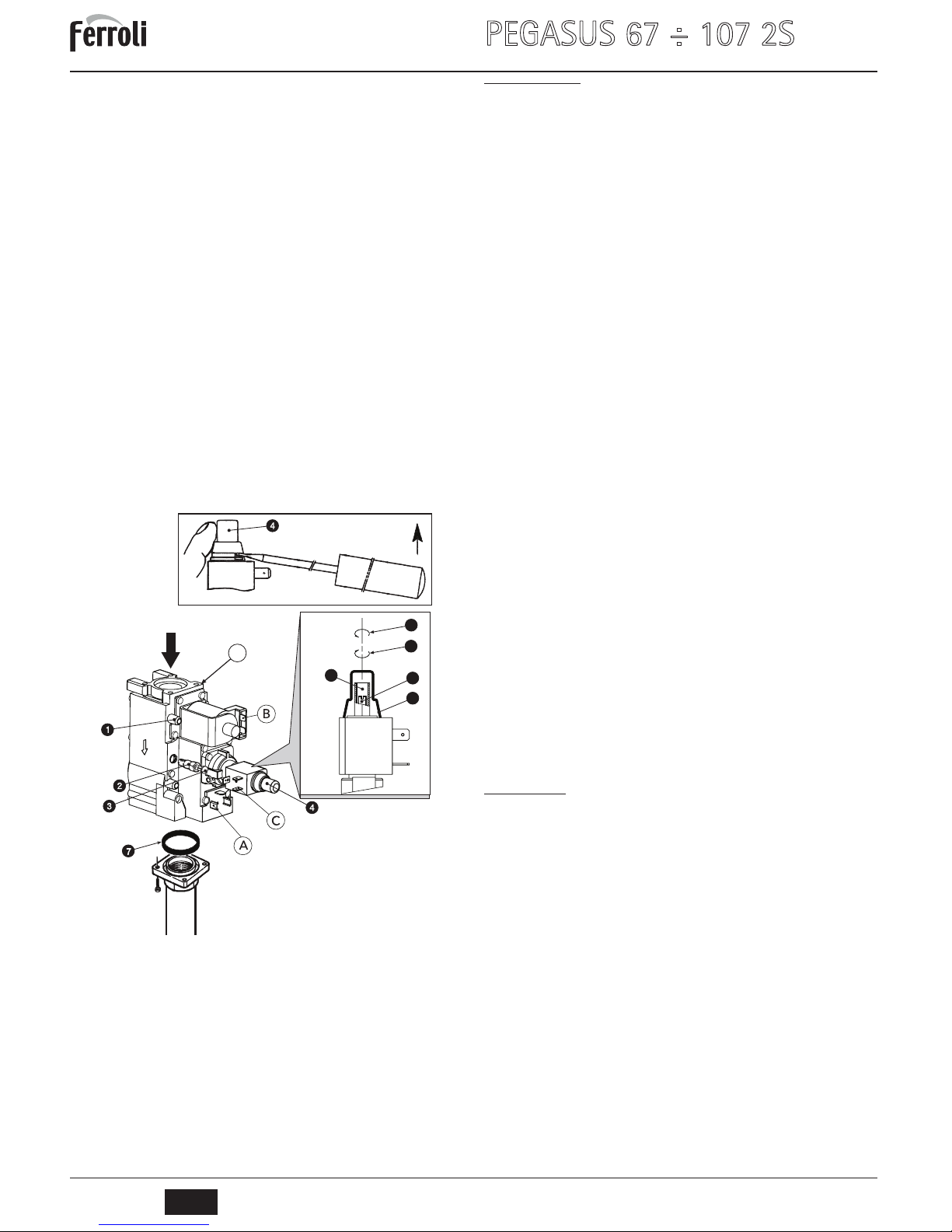
fig. 4 - Gas conversion
Key of main components
1 Pressure point upstream
2 Ignition "STEP" regulator for liquefied gas
3 Plug
4 Protection cap
5 Pressure adjustment screw for max. power
6 Pressure adjustment screw for min. power (1st stage)
7 O-ring
8 Decrease
9 Increase
V Honeywell valve VR 4601 CB
Key of electrical connections
A + B = Connections fed for min. power (1st stage)
A + B + C = Connections fed for max. power (2nd stage)
4.2 Commissioning
B
Commissioning must be carried out by Qualified Personnel.
The following operations and checks must be made at first lighting, and after all maintenance work involving disconnection from the systems or work on safety devices or parts
of the boiler.
Before lighting the boiler
• Open any shutoff valves between the boiler and the system.
• Check the tightness of the gas system, proceeding with caution and using soapy water to check for any leaks in connections.
• Fill the water system and make sure all air contained in the boiler and the system
has been vented by opening the air valve on the boiler and any vent valves in the
system.
• Make sure there are no water leaks in the system or boiler.
• Make sure the electrical system is properly connected.
• Make sure the unit is connected to an efficient earthing system.
• Make sure the pressure and gas flow values are those required for heating.
• Make sure there are no flammable liquids or materials in the immediate vicinity of
the boiler.
Lighting the boiler
• Open the gas cock ahead of the boiler.
• Vent the air from the pipe ahead of the gas valve.
• Turn on or insert the switch or plug ahead of the boiler.
• Turn the boiler switch (pos. 8 - fig. 1) to position 1.
• Turn the knob 7 (fig. 1) to a value above 50°C and that of the room thermostat (if
present) to the required temperature. The burner will light and the boiler starts to
work automatically, controlled by its adjustment and safety devices.
B
If, after correctly carrying out the lighting procedure , the burners do not light
and the button light comes on, wait about 15 seconds and then press the
above-mentioned button. The reset controller will repeat the ignition cycle. If the
burners do not light after the second attempt, consult the sec. 4.4.
The boiler switch 8 has 3 positions "0-1-TEST"; the first two have the on-off
function, the third (unstable) must only be used for service and maintenance
purposes.
A
In case of a power failure while the boiler is working, the burners will go out and
relight automatically when the power is restored.
Checks during operation
• Make sure the fuel circuit and water systems are tight.
• Check the efficiency of the flue and fume ducts while the boiler is working.
• Make sure the water is circulating properly between the boiler and the system.
• Check correct lighting of the boiler, by turning it on and off several times using the
room thermostat or boiler thermostat.
• Make sure the fuel consumption indicated on the meter matches that given in the
technical data table in cap. 5.
Turning off
To temporarily turn the boiler off, just set the boiler switch 8 (fig. 1) to 0.
To turn the boiler off for an extended period:
• Turn the knob of the boiler switch 8 (fig. 1) to 0;
• Close the gas cock ahead of the boiler;
• Disconnect the power to the unit;
B
To avoid damage caused by freezing during long idle periods in winter, it is advisable to drain all the water from the boiler and the system; or add a suitable
antifreeze to the heating system
4.3 Maintenance
B
THE FOLLOWING OPERATIONS MUST ONLY BE CARRIED OUT BY
QUALIFIED PERSONNEL.
Seasonal inspection of the boiler and flue
It is advisable to carry out the following checks at least once a year:
• The control and safety devices (gas valve, thermostats, etc.) must function correctly.
• The fume ducts must be free of obstructions and leaks.
• The gas and water systems must be tight.
• The burner and boiler shell must be clean. Follow the instructions in the next section.
• The electrodes must be free of deposits and properly positioned (see fig. 11).
• The water pressure in the system when cold must be approx. 1 bar; otherwise bring
it to that value.
• The expansion tank, if present, must be filled.
• The gas delivery and pressure must correspond to that given in the technical data
table (see sec. 5.3).
• The circulating pumps must not be blocked.
Safety devices
The boiler PEGASUS 67 ÷ 107 2S is equipped with devices that guarantee safety in case
of operation faults.
Manual-reset temperature limiter (safety thermostat)
This device prevents the water temperature in the system from exceeding boiling point.
The maximum activation temperature is 110°C.
Resetting of the temperature limiter can only occur on cooling of the boiler (the temper-
ature must drop by at least 10°C) and identification and consequent elimination of the
problem that caused the shutdown. To reset the temperature limiter, unscrew the cover
3 of fig. 1 and press the button below.
8
9
5
4
6
V
Page 5

PEGASUS 67 ÷ 107 2S
29
EN
cod. 3540S430 - 11/2009 (Rev. 00)
Fume sensor (fume thermostat) safety device
The boiler is equipped with a fume evacuation control device (fume sensor - ref. 4 of
fig. 1). In case of anomalies in the fume exhaust system with consequent return of burnt
gases in the room, the unit shuts down. The antiwind grille is equipped with a temperature sensor bulb for detecting and controlling the fume temperature.
Any leaks of burnt gases into the room cause an increase in the temperature detected
by the bulb, which causes the boiler to turn off within 2 minutes, shutting off the gas to
the burner. If the fume sensor cuts in, unscrew the protection cover (ref. 4 of fig. 1) located on the control panel and manually reset the device. The boiler will resume operation.
If the sensor has to be replaced due to a fault, only use original accessories and ensure
that the electrical connections and positioning of the bulb are correctly carried out.
B
The fume sensor must not be cut out for any reason!
Opening the front casing
To open the front panel of the boiler, refer to the sequence in fig. 5.
fig. 5 - Front panel opening
B
Before carrying out any operation inside the boiler, disconnect the electrical
power supply and close the gas cock upstream.
Combustion analysis
A fume sampling point has been included inside the boiler, in the top part of the antibackflow device (see fig. 6).
To take the sample:
1. Remove the boiler top panel
2. Remove the insulation placed over the anti-backflow device
3. Open the fume sampling point;
4. Insert the probe;
5. Adjust the boiler temperature to max.
6. Wait 10-15 minutes for the boiler to stabilise*
7. Take the measurement.
fig. 6 - Combustion analysis
A
Analyses made with an unstabilised boiler can cause measurement errors.
Burner assembly removal and cleaning
To remove the burner assembly:
• Disconnect the power supply and turn off the gas ahead of the boiler.
• Undo the two screws securing the electronic flame controllers to the gas valve
(fig. 7) and remove them from the gas valves (fig. 8).
• For models 97 2S and 107 2S with 2 gas valves, also undo the 2 screws securing
the 2 electrical connectors that feed the second valve and remove them.
• Disconnect the ignition and ionisation cables from the electrode assembly.
• Undo the nut fixing the gas supply pipe ahead of the gas valve (fig. 9). For models
97 2S and 107 2S, undo the 2 nuts.
• Undo the two nuts fixing the combustion chamber door to the cast iron elements of
the boiler (fig. 10).
• Remove the burner assembly and combustion chamber door.
Check and clean the burners. Only use a non-metallic brush or compressed air to clean
the burners; never use chemical products.
On completion, refit everything in reverse order.
fig. 7 - Undo the control unit screws
fig. 8 - Remove the control unit
fig. 9 - Undo the gas valve nut
fig. 10 - Undo the combustion chamber door nuts
Page 6

PEGASUS 67 ÷ 107 2S
30
EN
cod. 3540S430 - 11/2009 (Rev. 00)
Pilot burner assembly
fig. 11 - Pilot burner
1 Combustion chamber door
2 Inspection door
3 Pilot burner
4 Ignition electrode
5 Detection electrode
6 Pilot nozzle
7 High voltage cable
8 Gas supply pipe
Cleaning the boiler and flue
For proper cleaning of the boiler (see fig. 12):
• Turn off the gas ahead of the unit and disconnect the power supply
• Remove the front panel of the boiler (fig. 5).
• Lift the casing cover by pressing upwards.
• Remove the insulation 5 covering the anti-backflow device.
• Remove the fume chamber closing plate and insulation.
• Remove the burner assembly (see previous par.)
• Clean from the top downwards, using a flue brush. The same operation can be carried out from the bottom upwards.
• Clean the fume evacuation ducts between the cast iron elements of the boiler shell
with an aspirator.
• Carefully refit all the previously removed parts and check the tightness of the gas
circuit and the combustion ducts.
• During cleaning be careful not to damage the bulb of the fume thermostat fitted on
the back of the fume chamber.
fig. 12 - Boiler cleaning
1 Casing cover
2 Fume chamber closing plate
3 Flue brush
4 Combustion analysis plug
5 Insulation
4.4 Troubleshooting
A
To avoid unnecessary expense, before calling the After-Sales Service make
sure the boiler has not stopped due to no electricity or gas.
3
3 ÷ 4 mm
5
8
4
3
2
1
4
5
Fault Cause / Cure
After several lighting attempts, the
electronic controller shuts down the
boiler.
Clean the pilot burner nozzles with compressed air.
Check the regular gas flow to the boiler and that the air has been eliminated
from the pipes.
Make sure the electrodes are correctly positioned and free of deposits (see
fig. 11).
Make sure the boiler is connected to an efficient earth connection.
Check the connections at the ignition and ionisation electrodes.
The electrodes are not discharging
in the ignition phase.
Make sure the electrodes are correctly positioned and free of deposits (see
fig. 11).
Control thermostat adjusted too low.
Check the power supply.
Check the connections at the ignition and ionisation electrodes.
Check the connections at the electronic flame controller.
Make sure LINE-NEUTRAL are not inverted and that the earth contacts are effi-
cient.
Check the inlet gas pressure and any open pressure switches.
Reset the safety thermostat.
Reset the fume thermostat.
Make sure the room thermostat is closed.
The burner burns poorly: flames
too high, too low or too yellow
Gas valve filter dirty.
Check the gas supply pressure.
Gas nozzles dirty.
Make sure the boiler is not dirty.
Make sure the ventilation in the room where the unit is located is sufficient for
proper combustion.
Smell of unburnt gas Make sure the boiler is clean.
Check the flue draught.
Check that gas consumption is not excessive.
The boiler works but the temperature does not increase
Check correct operation of the 2-stage control thermostat.
Make sure the gas valve 2nd stage operator (max. power) is fed.
Check that gas consumption is not less than that provided for.
Make sure the boiler is perfectly clean.
Make sure the boiler is adequate for the system.
Make sure the heating pump is not blocked.
Temperature of water to the system
too high or too low
Check correct operation of the 2-stage control thermostat.
Make sure the heating pump is not blocked.
Make sure the characteristics of the circulating pump are adequate for the sys-
tem.
Explosion at burner. Delay on ignition
Make sure the gas pressure is sufficient and that the boiler shell is not dirty.
The control thermostat is reactivated with too great a temperature
difference
Make sure the bulb is properly inserted in the sheath.
Check operation of the 2-stage thermostat .
The boiler produces condensate Make sure the boiler is not operating at too low a temperature (below 50°C).
Check regular gas consumption.
Check the efficiency of the flue.
The boiler shuts down for no apparent reason
Safety thermostat activation due to an overtemperature.
Fume thermostat activation.
Page 7

PEGASUS 67 ÷ 107 2S
31
EN
cod. 3540S430 - 11/2009 (Rev. 00)
5. TECHNICAL DATA AND CHARACTERISTICS
5.1 Dimensions and connections
fig. 13 - Dimensions and connections
Table. 1
5.2 General view and main components
fig. 14 - General view and main components
Key
1 Pilot burner assembly
2 Gas valve for all models
3 Electronic flame controller
11 Automatic air vent
12 2nd gas valve (only models 107 2S and 97 2S)
13 Boiler drain cock
14 Burner assembly
15 Burner pressure point
16 Water pressure switch
5.3 Technical data table
5.4 Diagrams
Pressure loss
Key
A Pressure losses m H
2
O column
B Delivery m
3
/h
Type and model A B C
a1
heating
return
a2
heating
delivery
a3
Gas
inlet
PEGASUS 67 2S
760 100 180 1” 1/4 1” 1/4 3/4”
PEGASUS 77 2S
850 110 200 1” 1/4 1” 1/4 3/4”
PEGASUS 87 2S
930 110 200 1” 1/4 1” 1/4 3/4”
PEGASUS 97 2S
1020 110 200 1” 1/4 1” 1/4 3/4”
PEGASUS 107 2S
1100 120 220 1” 1/4 1” 1/4 3/4”
C
42
32
182
492
592
A
970
760
B
16
12
13
14
1
2
3
11
15
Model 67 2S 77 2S 87 2S 97 2S 107 2S
Number of elements no. 7 8 9 10 11
Max. heating capacity kW 73.3 84.2 95.2 106.0 117.0 (Q)
Min. heating capacity kW 31.0 35.7 40.3 45.0 49.0 (Q)
Max. heat output in heating kW 67.0 77.0 87.0 97.0 107.0 (P)
Min. heat output in heating kW 27.3 31.4 35.5 39.6 43.0 (P)
Efficiency Pmax (80-60°C) % 91.4 91.5 91.4 91.5 91.5
Efficiency 30% % 91.3 91.4 91.2 90.5 90.5
Efficiency class Directive 92/42 EEC
NOx emission class 2
Burner nozzles G20 no.x Ø 6 x 2.80 7 x 2.80 8 x 2.80 9 x 2.80 10 x 2.80
Gas supply pressure G20 mbar 20 20 20 20 20
Max. gas pressure at burner G20 mbar 13 13 13 13 13
Min. gas pressure at burner G20 mbar 2.5 2.5 2.5 2.5 2.5
Max. gas delivery G20
m
3
/h
7.76 8.91 10.07 11.22 12.38
Min. gas delivery G20
m
3
/h
3.28 3.78 4.26 4.76 5.19
Burner nozzles G31 no.x Ø 6 x 1.75 7 x 1.75 8 x 1.75 9 x 1.75 10 x 1.75
Gas supply pressure G31 mbar 37 37 37 37 37
Max. gas pressure at burner G31 mbar 35 35 35 35 35
Min. gas pressure at burner G31 mbar 6 6 6 6 6
Max. gas delivery G31 kg/h 5.74 6.59 7.45 8.30 9.16
Min. gas delivery G31 kg/h 2.43 2.80 3.16 3.52 3.84
Max. working pressure in heating bar 6 6 6 6 6 (PMS)
Min. working pressure in heating bar 0.3 0.3 0.3 0.3 0.3
Max. heating temperature °C 95 95 95 95 95 (tmax)
Heating water content L 19.1 21.6 24.1 26.6 29.1
Protection rating IP X0D X0D X0D X0D X0D
Power supply voltage V/Hz 230/50 230/50 230/50 230/50 230/50
Electrical power input W 30 30 30 30 30
Empty weight 275 304 333 362 390
0.5 1 1.5 2 2.5 3 3.5 4 4.5 5 5.5 6 6.5 7 7.5 8 8.5 9 9.5 10 10.5
0
0.25
0.5
0.75
1
1.25
1.5
1.75
2
2.25
2.5
2.75
3
67
77
87
97
107
m C.A.
m3/h
Page 8

PEGASUS 67 ÷ 107 2S
32
EN
cod. 3540S430 - 11/2009 (Rev. 00)
5.5 Wiring diagrams
Connection wiring diagram
fig. 15 - Electrical connection diagram
Main wiring diagram
fig. 16 - Main wiring diagram
A
Connections in broken lines to be carried out by the installer
Key
24 - Ignition electrode
32 - Heating circulating pump (not supplied)
44a - Gas valve
44b - 2
nd
Gas valve (only models 97 2S and 107 2S)
49 - Safety thermostat
72 - Room thermostat (not supplied)
82 - Detection electrode
83 - Electronic controller
92 - Fume thermostat
98 - Switch
129 - Reset button with indicator lamp
159 - Test button
160 - Auxiliary contact
167a - Gas valve 2nd stage operator
167b - 2nd Gas valve 2nd stage operator (only models 97 2S and 107 2S)
170 - 1st stage control thermostat
171 - 2nd stage control thermostat
242 - Connector for thermostatic controller
Page 9

Declaración de conformidad
El fabricante: FERROLI S.p.A.
Dirección: Via Ritonda 78/a 37047 San Bonifacio (Verona)
declara que este equipo satisface las siguientes directivas CEE:
• Directiva de Aparatos de Gas 90/396
• Directiva de Rendimientos 92/42
• Directiva de Baja Tensión 73/23 (modificada por la 93/68)
• Directiva de Compatibilidad Electromagnética 89/336 (modificada por la 93/68)
Presidente y representante legal
Caballero del Trabajo
Dante Ferroli
ES
Dichiarazione di conformità
Il costruttore: FERROLI S.p.A.
Indirizzo: Via Ritonda 78/a 37047 San Bonifacio VR
dichiara che questo apparecchio è conforme alle seguenti direttive CEE:
• Direttiva Apparecchi a Gas 90/396
• Direttiva Rendimenti 92/42
• Direttiva Bassa Tensione 73/23 (modificata dalla 93/68)
• Direttiva Compatibilità Elettromagnetica 89/336 (modificata dalla 93/68)
Presidente e Legale rappresentante
Cav. del Lavoro
Dante Ferroli
IT
Uygunluk beyani
ømalatçi: FERROLI S.p.A.
Adres: Via Ritonda 78/a 37047 San Bonifacio VR
bu cihazin; asagida yer alan AET(EEC) yönergelerine uygunluk içinde oldugunu beyan etmektedir:
• 90/396 Gazla çalistirilan üniteler için Yönetmelik
• 92/42 Randiman/Verimlilik Yönetmeligi
• Yönerge 73/23, Düsük Voltaj (93/68 nolu direktifle degisiklige ugratildi)
• 89/336 Elektromanyetik Uygunluk Yönetmeligi (93/68 ile degisiklik yapilmistir)
Baskan ve yasal temsilci
øú. Dep.
Dante Ferroli
TR
Declaration of conformity
Manufacturer: FERROLI S.p.A.
Address: Via Ritonda 78/a 37047 San Bonifacio VR Italy
declares that this unit complies with the following EU directives:
• Gas Appliance Directive 90/396
• Efficiency Directive 92/42
• Low Voltage Directive 73/23 (amended by 93/68)
• Electromagnetic Compatibility Directive 89/336 (amended by 93/68)
President and Legal Representative
Cav. del Lavoro
Dante Ferroli
EN
Page 10

Ⱦɟɤɥɚɪɚɰɿɹɩɪɨɜɿɞɩɨɜɿɞɧɿɫɬɶ
ȼɢɪɨɛɧɢɤ: ɤɨɦɩɚɧiɹ FERROLI S.p.A.
ɡɚɚɞɪɟɫɨɸ: Via Ritonda 78/a 37047 San Bonifacio VR
ɡɚɹɜɥɹɽ, ɳɨɰɟɣɚɩɚɪɚɬɜɿɞɩɨɜɿɞɚɽɭɫɿɦɧɚɫɬɭɩɧɢɦȾɢɪɟɤɬɢɜɚɦȯɋ:
• Ⱦɢɪɟɤɬɢɜɚȯɋ 90/396 (Ⱦɢɪɟɤɬɢɜɚɩɪɨɡɛɥɢɠɟɧɧɹɩɪɚɜɨɜɢɯɧɨɪɦɤɪɚʀɧ-ɱɥɟɧɿɜȯɋɞɥɹɝɚɡɨ-ɪɨɡɯɿɞɧɢɯ
ɭɫɬɚɧɨɜɨɤ)
• Ⱦɢɪɟɤɬɢɜɚȯɋ 92/42 (ȾɢɪɟɤɬɢɜɚɩɪɨɜɢɦɨɝɢɄɉȾɞɥɹɧɨɜɢɯɜɨɞɨɝɪɿɣɧɢɯɤɨɬɥɿɜ, ɩɪɚɰɸɸɱɢɯɧɚɪɿɞɢɧɧɨɦɭ
ɿɝɚɡɨɩɨɞɿɛɧɨɦɭɩɚɥɢɜɿ)
• Ⱦɢɪɟɤɬɢɜɚȯɋ 73/23 (Ⱦɢɪɟɤɬɢɜɚɩɪɨɡɛɥɢɠɟɧɧɹɩɪɚɜɨɜɢɯɧɨɪɦɤɪɚʀɧ-ɱɥɟɧɿɜȯɋ, ɳɨɫɬɨɫɭɸɬɶɫɹ
ɟɥɟɤɬɪɨɨɛɥɚɞɧɚɧɧɹ, ɹɤɟɜɢɤɨɪɢɫɬɨɜɭɽɬɶɫɹɜɩɟɜɧɢɯɦɟɠɚɯɧɚɩɪɭɝɢ) (ɡɦɿɧɟɧɚȾɢɪɟɤɬɢɜɨɸȯɋ 93/68)
• Ⱦɢɪɟɤɬɢɜɚȯɋ 89/336 (Ⱦɢɪɟɤɬɢɜɚɩɪɨɩɪɢɜɟɞɟɧɧɹɭɜɿɞɩɨɜɿɞɧɿɫɬɶɡɚɤɨɧɨɞɚɜɫɬɜɤɪɚʀɧ-ɱɥɟɧɿɜɜɨɛɥɚɫɬɿ
ɟɥɟɤɬɪɨɦɚɝɧɿɬɧɨʀɫɭɦɿɫɧɨɫɬɿ) (ɡɦɿɧɟɧɚȾɢɪɟɤɬɢɜɨɸȯɋ 93/68).
ɉɪɟɡɢɞɟɧɬɿɡɚɤɨɧɧɢɣɩɪɟɞɫɬɚɜɧɢɤ
Ʉɚɜɚɥɟɪɩɪɚɰɿ
Dante Ferroli
UK
Ⱦɟɤɥɚɪɚɰɢɹɫɨɨɬɜɟɬɫɬɜɢɹ
ɂɡɝɨɬɨɜɢɬɟɥɶ: FERROLI S.p.A.,
ɚɞɪɟɫ: Via Ritonda 78/a 37047 San Bonifacio VR,
ɡɚɹɜɥɹɟɬ, ɱɬɨɧɚɫɬɨɹɳɟɟɢɡɞɟɥɢɟɫɨɨɬɜɟɬɫɬɜɭɟɬɫɥɟɞɭɸɳɢɦɞɢɪɟɤɬɢɜɚɦ CEE:
• Ⱦɢɪɟɤɬɢɜɚɩɨɝɚɡɨɜɵɦɩɪɢɛɨɪɚɦ 90/396
• ȾɢɪɟɤɬɢɜɚɩɨɄ.ɉ.Ⱦ. 92/42
• Ⱦɢɪɟɤɬɢɜɚɩɨɧɢɡɤɨɦɭɧɚɩɪɹɠɟɧɢɸ 73/23 (ɫɢɡɦɟɧɟɧɢɹɦɢ, ɜɧɟɫɟɧɧɵɦɢɞɢɪɟɤɬɢɜɨɣ 93/68)
• Ⱦɢɪɟɤɬɢɜɚɩɨɷɥɟɤɬɪɨɦɚɝɧɢɬɧɨɣɫɨɜɦɟɫɬɢɦɨɫɬɢ 89/336 (ɫɢɡɦɟɧɟɧɢɹɦɢ, ɜɧɟɫɟɧɧɵɦɢ
ɞɢɪɟɤɬɢɜɨɣ 93/68).
ɉɪɟɡɢɞɟɧɬɢɭɩɨɥɧɨɦɨɱɟɧɧɵɣɩɪɟɞɫɬɚɜɢɬɟɥɶ
Ʉɚɜɚɥɶɟɪɟɞɟɥɶɥɚɜɨɪɨ (ɩɨɱɟɬɧɵɣɬɢɬɭɥ, ɩɪɢɫɭɠɞɚɟɦɵɣ
ɝɨɫɭɞɚɪɫɬɜɨɦɡɚɡɚɫɥɭɝɢɜɪɭɤɨɜɨɞɫɬɜɟɩɪɨɦɵɲɥɟɧɧɨɫɬɶɸ)
Dante Ferroli
RU
Déclaration de conformité
Le constructeur : FERROLI S.p.A.
Adresse: Via Ritonda 78/a 37047 San Bonifacio VR
déclare que cet appareil est conforme aux directives CEE ci-dessous:
• Directives appareils à gaz 90/396
• Directive rendements 92/42
• Directive basse tension 73/23 (modifiée 93/68)
• Directive Compatibilité Electromagnétique 89/336 (modifiée 93/68)
Président et fondé de pouvoirs
Cav. du travail
Dante Ferroli
FR
Page 11

FERROLI S.p.A.
Via Ritonda 78/a
37047 San Bonifacio - Verona - ITALY
www.ferroli.it
 Loading...