

Page 1
ATLAS D 30 K 100
6
ISTRUZIONE PER L’USO L'INSTALLAZIONE E LA MANUTENZIONE
INSTRUCCIONES DE USO, INSTALACIÓN Y MANTENIMIENTO
KULLANMA, KURULUM VE BAKøM TALIMATLARø
INSTRUCTIONS FOR USE, INSTALLATION AND MAINTENANCE
cod. 3540S361 — 08/2009 (Rev. 00)
INSTRUCTIONS D'UTILISATION, D'INSTALLATION ET D'ENTRETIEN
ȅǻǾīǴǼȈ ȋȇdzȈǾȈ, ǼīȀǹȉDZȈȉǹȈǾȈ Ȁǹǿ ȈȊȃȉdzȇǾȈǾȈ
AANWIJZINGEN VOOR GEBRUIK, INSTALLATIE EN ONDERHOUD
ɊɍɄɈȼɈȾɋɌȼɈ ɉɈ ɗɄɋɉɅɍȺɌȺɐɂɂ, ɆɈɇɌȺɀɍ ɂ ɌȿɏɈȻɋɅɍɀɂȼȺɇɂɘ
Page 2
ATLAS D 30 K 100
IT
1. AVVERTENZE GENERALI
• Leggere ed osservare attentamente le avvertenze contenute in questo libretto di istruzioni.
• Dopo l’installazione della caldaia, informare l’utilizzatore sul funzionamento e consegnargli il presente manuale che costituisce parte integrante ed essenziale del prodotto e deve essere conservato con cura per ogni
ulteriore consultazione.
• L’installazione e la manutenzione devono essere effettuate in ottemperanza alle norme vigenti, secondo le
istruzioni del costruttore e devono essere eseguite da personale professionalmente qualificato. È vietato ogni
intervento su organi di regolazione sigillati.
• Un’errata installazione o una cattiva manutenzione possono causare danni a persone, animali o cose. È
esclusa qualsiasi responsabilità del costruttore per i danni causati da errori nell’installazione e nell’uso e comunque per inosservanza delle istruzioni.
• Prima di effettuare qualsiasi operazione di pulizia o di manutenzione, disinserire l’apparecchio dalla rete di
alimentazione agendo sull’interruttore dell’impianto e/o attraverso gli appositi organi di intercettazione.
• In caso di guasto e/o cattivo funzionamento dell’apparecchio, disattivarlo, astenendosi da qualsiasi tentativo
di riparazione o di intervento diretto. Rivolgersi esclusivamente a personale professionalmente qualificato.
L’eventuale riparazione-sostituzione dei prodotti dovrà essere effettuata solamente da personale professionalmente qualificato utilizzando esclusivamente ricambi originali. Il mancato rispetto di quanto sopra può
compromettere la sicurezza dell’apparecchio.
• Questo apparecchio dovrà essere destinato solo all’uso per il quale è stato espressamente previsto. Ogni
altro uso è da considerarsi improprio e quindi pericoloso.
• Gli elementi dell’imballaggio non devono essere lasciati alla portata di bambini in quanto potenziali fonti di
pericolo.
• Le immagini riportate nel presente manuale sono una rappresentazione semplificata del prodotto. In questa
rappresentazione possono esserci lievi e non significative differenze con il prodotto fornito.
2. ISTRUZIONI D’USO
2.1 Presentazione
Gentile Cliente,
La ringraziamo di aver scelto una caldaia FERROLI di concezione avanzata, tecnologia
d’avanguardia, elevata affidabilità e qualità costruttiva. La preghiamo di leggere attentamente il presente manuale perchè fornisce importanti indicazioni riguardanti la sicurezza
di installazione, uso e manutenzione.
ATLAS D 30 K 100 è un generatore di calore ad alto rendimento, per la produzione di
acqua calda sanitaria e per il riscaldamento, adatto a funzionare con bruciatori soffiati a
gas o gasolio. Il corpo caldaia è costituito da elementi in ghisa, assemblati con biconi e
tiranti in acciaio sovrapposti ad un bollitore per l’acqua calda sanitaria ad accumulo rapido, vetrificato, e protetto contro la corrosione da un anodo di magnesio. Il sistema di
controllo è a microprocessore con interfaccia digitale con funzionalità avanzate di termoregolazione.
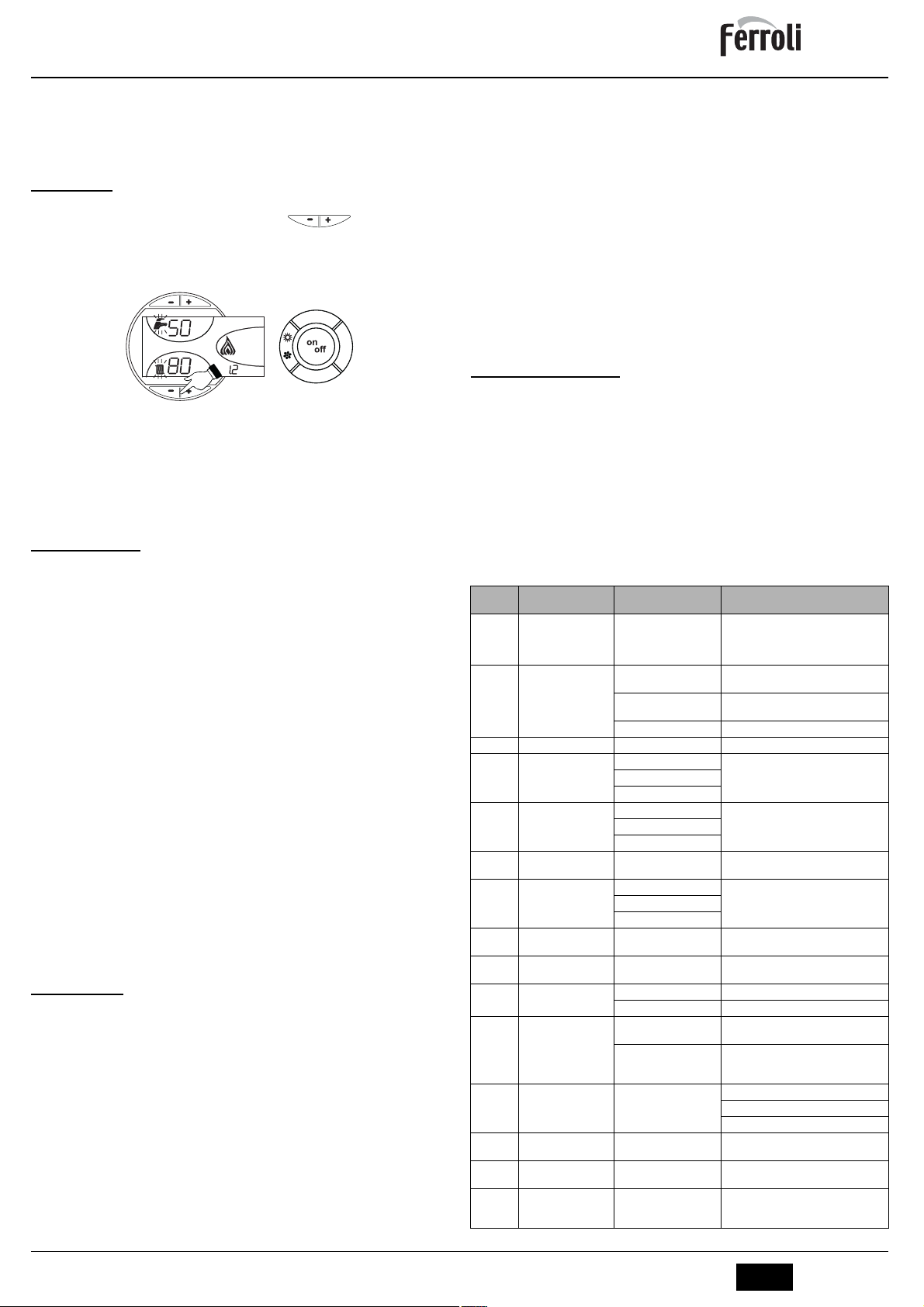
2.2 Pannello comandi
15 16
ecomfort
bar
5791021
o
c
e
f
o
m
r
o
t
c
m
o
d
e
r
t
e
e
s
13
27
12 1411
19
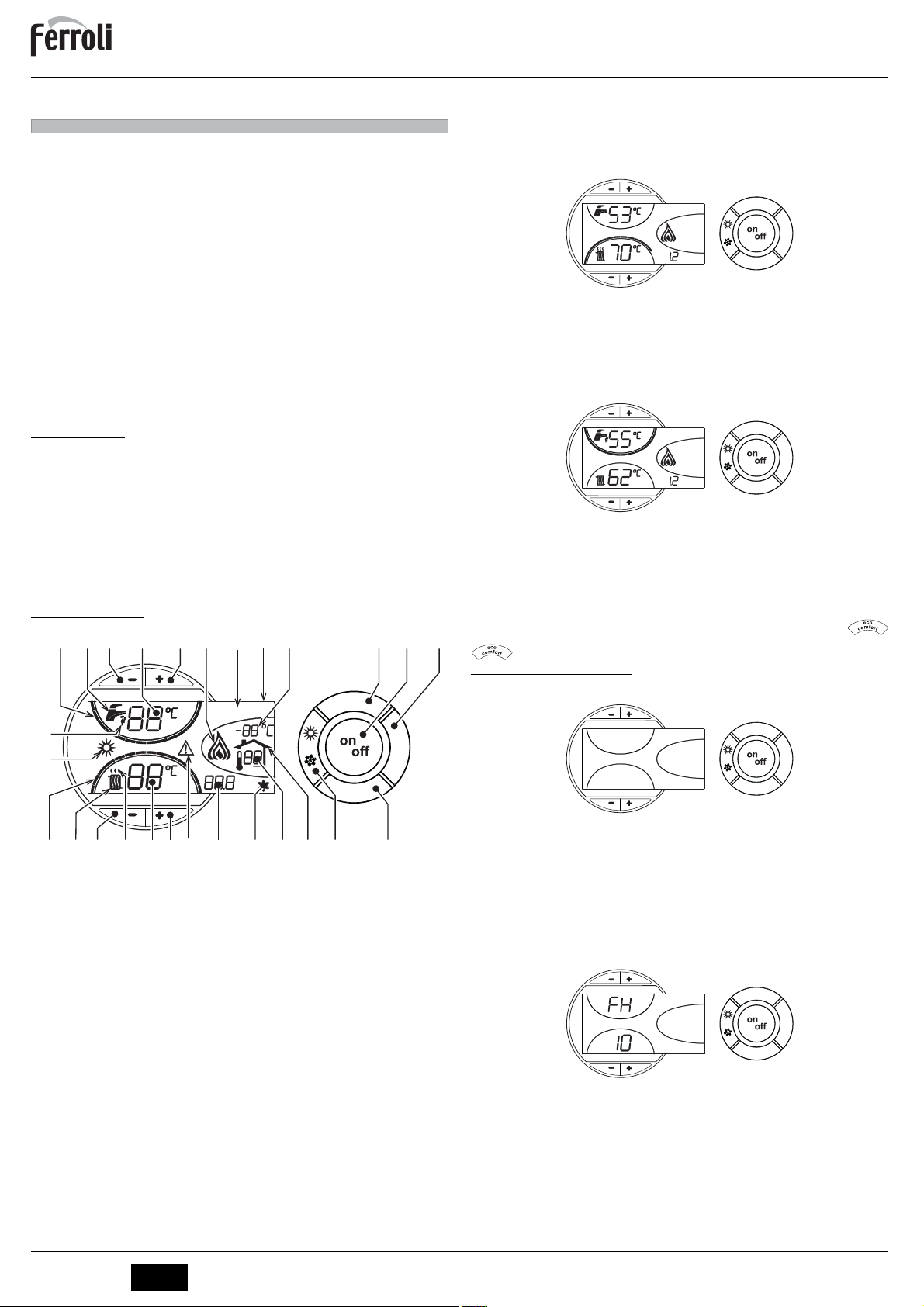
Indicazione durante il funzionamento
Riscaldamento
La richiesta riscaldamento (generata da Termostato Ambiente o Cronocomando Remoto) è indicata dal lampeggio dell'aria calda sopra il radiatore (part. 24 e 25 - fig. 1).
Le tacche di graduazione riscaldamento (part. 26 - fig. 1), si accendono man mano che
la temperatura del sensore riscaldamento raggiunge il valore impostato.
o
c
e
f
m
o
r
o
t
eco
bar
fig. 2
Sanitario (Comfort)
La richiesta sanitario (generata dal prelievo d’acqua calda sanitaria) è indicata dal lampeggio dell'acqua calda sotto il rubinetto (part. 12 e 13 - fig. 1). Accertarsi che sia attiva
la funzione Comfort (part. 15 - fig. 1)
Le tacche di graduazione sanitario (part. 11 - fig. 1), si accendono man mano che la temperatura del sensore sanitario raggiunge il valore impostato.
comfort
bar
fig. 3
Esclusione bollitore (economy)
Il riscaldamento/mantenimento in temperatura del bollitore può essere escluso dall'utente. In caso di esclusione, non vi sarà erogazione di acqua calda sanitaria.
Quando il riscaldamento del bollitore è attivo (impostazione di default), sul display è attivo il simbolo COMFORT (part. 15 - fig. 1), mentre quando è disinserito, sul display è
attivo il simbolo ECO (part. 15 - fig. 1)
Il bollitore può essere disattivato dall'utente (modalità ECO) premendo il tasto
(part. 7 - fig. 1). Per attivare la modalità COMFORT premere nuovamente il tasto
(part. 7 - fig. 1).
2.3 Accensione e spegnimento
Caldaia non alimentata elettricamente
c
m
o
d
e
r
t
e
e
s
o
c
e
f
m
o
r
o
t
c
m
o
d
e
r
t
e
e
s
o
c
e
f
m
o
r
o
t
c
m
o
d
e
r
t
e
e
s
2426
17182021222325
8643
fig. 1 - Pannello di controllo
Legenda
1 = Tasto decremento impostazione temperatura acqua calda sanitaria
2 = Tasto incremento impostazione temperatura acqua calda sanitaria
3 = Tasto decremento impostazione temperatura impianto riscaldamento
4 = Tasto incremento impostazione temperatura impianto riscaldamento
5 = Display
6 = Tasto selezione modalità Estate / Inverno
7 = Tasto selezione modalità Economy / Comfort
8 = Tasto Ripristino
9 = Tasto accensione / spegnimento apparecchio
10 = Tasto menù "Temperatura Scorrevole"
11 = Indicazione raggiungimento temperatura acqua calda sanitaria impostata
12 = Simbolo acqua calda sanitaria
13 = Indicazione funzionamento sanitario
14 = Impostazione / temperatura uscita acqua calda sanitaria
15 = Indicazione modalità Eco (Economy) o Comfort
16 = Temperatura sensore esterno (con sonda esterna opzionale)
17 = Compare collegando la Sonda esterna o il Cronocomando Remoto (opzionali)
18 = Temperatura ambiente (con Cronocomando Remoto opzionale)
19 = Indicazione bruciatore acceso
20 = Indicazione funzionamento antigelo
21 = Indicazione pressione impianto riscaldamento
22 = Indicazione Anomalia
23 = Impostazione / temperatura mandata riscaldamento
24 = Simbolo riscaldamento
25 = Indicazione funzionamento riscaldamento
26 = Indicazione raggiungimento temperatura mandata riscaldamento impostata
27 = Indicazione modalità Estate
fig. 4 - Caldaia non alimentata elettricamente
Togliendo alimentazione elettrica e/o gas all'apparecchio il sistema antigelo
non funziona. Per lunghe soste durante il periodo invernale, al fine di evitare
B
danni dovuti al gelo, è consigliabile scaricare tutta l’acqua della caldaia, quella
sanitaria e quella dell’impianto; oppure scaricare solo l’acqua sanitaria e introdurre l’apposito antigelo nell’impianto di riscaldamento, conforme a quanto prescritto alla sez. 3.3.
Accensione caldaia
• Aprire le valvole di intercettazione combustibile.
• Fornire alimentazione elettrica all'apparecchio.
o
c
e
f
o
m
r
o
t
c
m
o
d
e
r
t
e
e
s
fig. 5 - Accensione caldaia
• Per i successivi 120 secondi il display visualizza FH che identifica il ciclo di sfiato
aria dall'impianto riscaldamento.
• Durante i primi 5 secondi il display visualizza anche la versione software della scheda.
• Scomparsa la scritta FH, la caldaia è pronta per funzionare automaticamente ogni
qualvolta si prelevi acqua calda sanitaria o vi sia una richiesta al termostato ambiente.
2
IT
cod. 3540S361 - 08/2009 (Rev. 00)
Page 3
ATLAS D 30 K 100
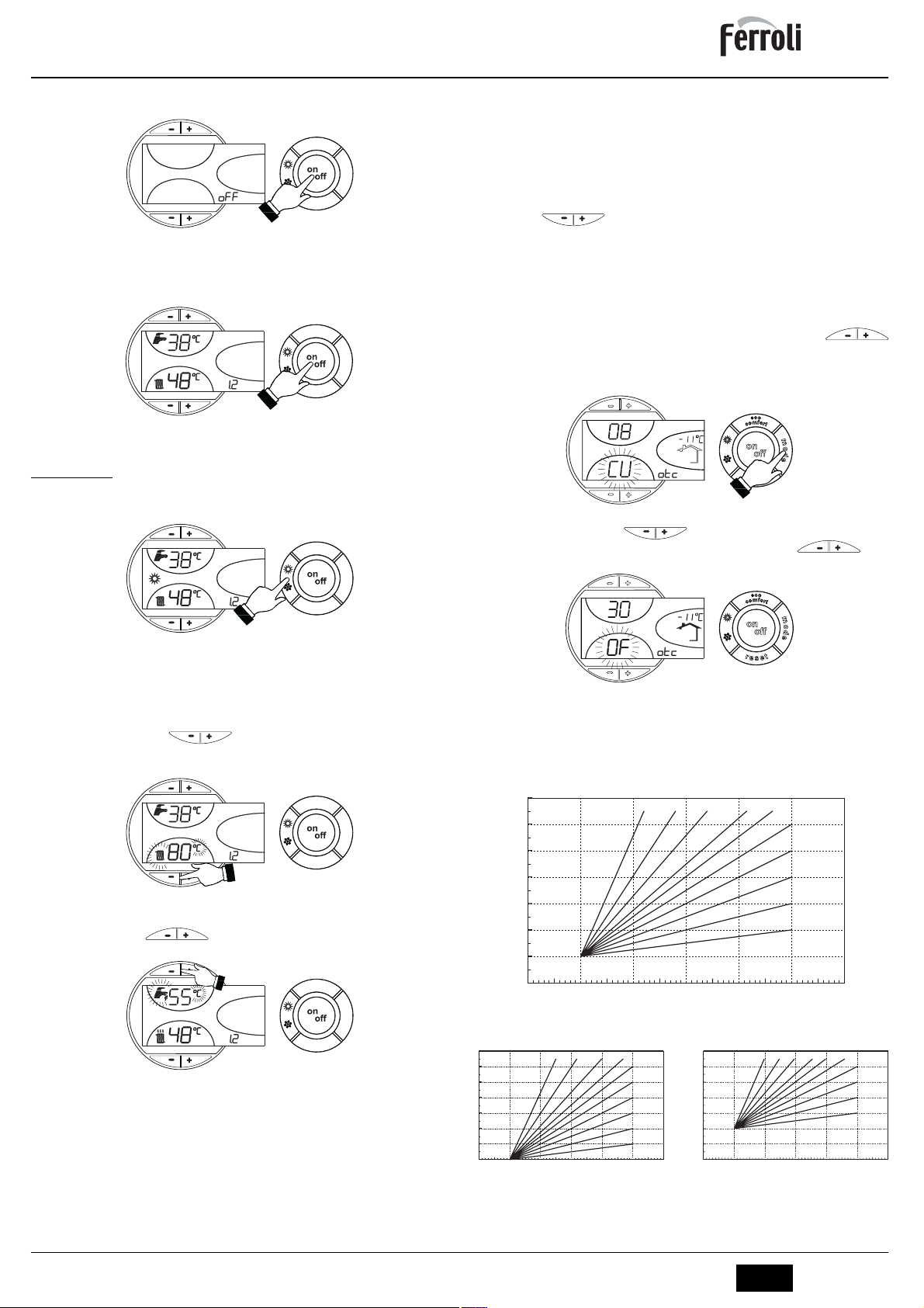
Spegnimento caldaia
Premere il tasto
on/off
(part. 9 -
fig. 1
) per 1 secondo.
o
c
e
f
m
o
r
o
t
c
m
o
d
e
r
t
e
e
s
fig. 6 - Spegnimento caldaia
Quando la caldaia viene spenta, la scheda elettronica è ancora alimentata elettricamente.
È disabilitato il funzionamento sanitario e riscaldamento. Rimane attivo il sistema antigelo.
on/off
(part. 9
fig. 1
o
f
o
r
t
t
e
) per 1 secondo.
m
o
d
e
Per riaccendere la caldaia, premere nuovamente il tasto
eco
bar
c
e
m
o
c
r
e
s
fig. 7
La caldaia sarà immediatamente pronta per funzionare ogni qualvolta si prelevi acqua
calda sanitaria o vi sia una richiesta al termostato ambiente.
2.4 Regolazioni
Commutazione Estate/Inverno
Premere il tasto estate/inverno (part. 6 - fig. 1) per 1 secondo.
o
c
e
f
m
o
r
o
t
eco
bar
c
m
o
d
e
r
t
e
e
s
Temperatura scorrevole
Quando viene installata la sonda esterna (opzionale) sul display del pannello comandi
(part. 5 - fig. 1) è visualizzata l’attuale temperatura esterna rilevata dalla sonda esterna
stessa. Il sistema di regolazione caldaia lavora con “Temperatura Scorrevole”. In questa
modalità, la temperatura dell’impianto di riscaldamento viene regolata a seconda delle
condizioni climatiche esterne, in modo da garantire un elevato comfort e risparmio energetico durante tutto il periodo dell’anno. In particolare, all’aumentare della temperatura
esterna viene diminuita la temperatura di mandata impianto, a seconda di una determinata “curva di compensazione”.
Con regolazione a Temperatura Scorrevole, la temperatura impostata attraverso i tasti
riscaldamento (part. 3 e 4 - fig. 1) diviene la massima temperatura di mandata impianto. Si consiglia di impostare al valore massimo per permettere al sistema di
regolare in tutto il campo utile di funzionamento.
La caldaia deve essere regolata in fase di installazione dal personale qualificato. Eventuali adattamenti possono essere comunque apportati dall’utente per il miglioramento
del comfort.
Curva di compensazione e spostamento delle curve
Premendo una volta il tasto mode (part. 10 - fig. 1) viene visualizzata l’attuale curva di
compensazione (fig. 11) ed è possibile modificarla con i tasti sanitario
(part. 1 e 2 - fig. 1).
Regolare la curva desiderata da 1 a 10 secondo la caratteristica (fig. 13).
Regolando la curva a 0, la regolazione a temperatura scorrevole risulta disabilitata.
fig. 11 - Curva di compensazione
Premendo i tasti riscaldamento (part. 3 e 4 - fig. 1) si accede allo spostamento parallelo delle curve (fig. 14), modificabile con i tasti sanitario (part.
1 e 2 - fig. 1).
fig. 8
Il display attiva il simbolo Estate (part. 27 - fig. 1): la caldaia erogherà solo acqua sanitaria. Rimane attivo il sistema antigelo.
Per disattivare la modalità Estate, premere nuovamente il tasto estate/inverno (part. 6
- fig. 1) per 1 secondo.
Regolazione temperatura riscaldamento
Agire sui tasti riscaldamento (part. 3 e 4 - fig. 1) per variare la temperatura
da un minimo di 30 °C ad un massimo di 90 °C; si consiglia comunque di non far funzionare la caldaia al di sotto dei 45 °C.
o
c
e
f
o
m
r
o
t
eco
bar
c
m
o
d
e
r
t
e
e
s
fig. 9
Regolazione temperatura sanitario
Agire sui tasti sanitario (part. 1 e 2 - fig. 1) per variare la temperatura da
un minimo di 10°C ad un massimo di 65°C.
o
c
e
f
m
o
r
o
t
eco
bar
c
m
o
d
e
r
t
e
e
s
fig. 10
Regolazione della temperatura ambiente (con termostato ambiente opzionale)
Impostare tramite il termostato ambiente la temperatura desiderata all’interno dei locali.
Nel caso non sia presente il termostato ambiente la caldaia provvede a mantenere l’impianto alla temperatura di setpoint mandata impianto impostata.
Regolazione della temperatura ambiente (con cronocomando remoto opzionale)
Impostare tramite il cronocomando remoto la temperatura ambiente desiderata all’interno dei locali. La caldaia regolerà l'acqua impianto in funzione della temperatura ambiente richiesta. Per quanto riguarda il funzionamento con cronocomando remoto, fare
riferimento al relativo manuale d'uso.
fig. 12 - Spostamento parallelo delle curve
Premendo nuovamente il tasto mode (part. 10 - fig. 1) si esce dalla modalità regolazione
curve parallele.
Se la temperatura ambiente risulta inferiore al valore desiderato si consiglia di impostare
una curva di ordine superiore e viceversa. Procedere con incrementi o diminuzioni di una
unità e verificare il risultato in ambiente.
90
85
80
70
60
50
40
30
20
20 10 0 -10 -20
68910 7
5
4
3
2
1
fig. 13 - Curve di compensazione
OFFSET = 20 OFFSET = 40
90
85
80
70
60
50
40
30
20
20 10 0 -10 -20
8910
7
6
5
4
3
2
1
90
85
80
70
60
50
40
30
20
20 10 0 -10 -20
568910 7
4
3
2
1
fig. 14 - Esempio di spostamento parallelo delle curve di compensazione
6
cod. 3540S361 - 08/2009 (Rev. 00)
IT
3
Page 4
ATLAS D 30 K 100
Regolazioni da Cronocomando Remoto
Se alla caldaia è collegato il Cronocomando Remoto (opzionale), le regolazioni
A
descritte in precedenza vengono gestite secondo quanto riportato nella
tabella 1. Inoltre, sul display del pannello comandi (part. 5 - fig. 1), è visualizzata l'attuale temperatura ambiente rilevata dal Cronocomando Remoto stesso.
Tabella. 1
Regolazione temperatura riscaldamento
Regolazione temperatura sanitario
Commutazione Estate/Inverno
Selezione Eco/Comfort
Temperatura Scorrevole
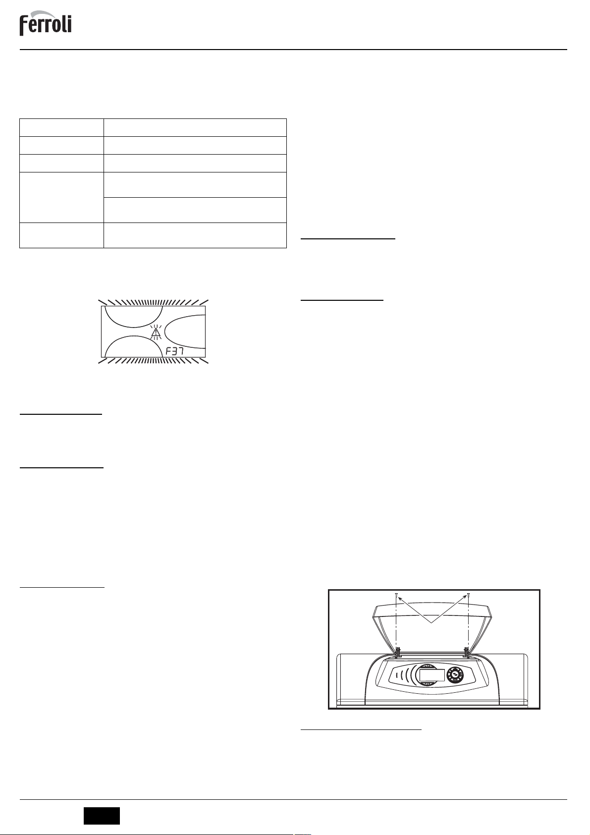
Regolazione pressione idraulica impianto
La pressione di caricamento ad impianto freddo, letta sul display, deve essere di circa
1,0 bar. Se la pressione dell'impianto scende a valori inferiori al minimo, la scheda caldaia attiverà l'anomalia F37 (fig. 15).
fig. 15 - Anomalia pressione impianto insufficiente
Una volta ripristinata la pressione impianto, la caldaia attiverà il ciclo di sfiato
A
aria di 120 secondi identificato dal display con FH.
3. INSTALLAZIONE
3.1 Disposizioni generali
L'INSTALLAZIONE DELLA CALDAIA DEVE ESSERE EFFETTUATA SOLTANTO DA
PERSONALE SPECIALIZZATO E DI SICURA QUALIFICAZIONE, OTTEMPERANDO A
TUTTE LE ISTRUZIONI RIPORTATE NEL PRESENTE MANUALE TECNICO, ALLE DISPOSIZIONI DI LEGGE VIGENTI, ALLE PRESCRIZIONI DELLE NORME NAZIONALI
E LOCALI E SECONDO LE REGOLE DELLA BUONA TECNICA.
3.2 Luogo d’installazione
La caldaia deve essere installata in apposito locale con aperture di aerazione verso
l’esterno secondo quanto prescritto dalle norme vigenti. Se nello stesso locale vi sono
più bruciatori o aspiratori che possono funzionare assieme, le aperture di aerazione devono essere dimensionate per il funzionamento contemporaneo di tutti gli apparecchi.Il
luogo di installazione deve essere privo di oggetti o materiali infiammabili, gas corrosivi
polveri o sostanze volatili che, richiamate dal ventilatore del bruciatore possano ostruire
i condotti interni del bruciatore o la testa di combustione. L’ambiente deve essere asciutto e non esposto a pioggia, neve o gelo.
Se l’apparecchio viene racchiuso entro mobili o montato affiancato lateralmen-
A
te, deve essere previsto lo spazio per lo smontaggio della mantellatura e per le
normali attività di manutenzione. Accertarsi in particolare che dopo il montaggio
della caldaia con il bruciatore sulla porta anteriore, quest'ultima possa aprirsi
senza che il bruciatore vada a sbattere contro pareti o altri ostacoli.
3.3 Collegamenti idraulici
La potenzialità termica dell’apparecchio va stabilita preliminarmente con un calcolo del
fabbisogno di calore dell’edificio secondo le norme vigenti. L’impianto deve essere corredato di tutti i componenti per un corretto e regolare funzionamento. Si consiglia d’interporre, fra caldaia ed impianto di riscaldamento, delle valvole d’intercettazione che
permettano, se necessario, d’isolare la caldaia dall’impianto.
Lo scarico della valvola di sicurezza deve essere collegato ad un imbuto o tubo
di raccolta, per evitare lo sgorgo di acqua a terra in caso di sovrapressione nel
B
circuito di riscaldamento. In caso contrario, se la valvola di scarico dovesse intervenire allagando il locale, il costruttore della caldaia non potrà essere ritenuto responsabile.
Non utilizzare i tubi degli impianti idraulici come messa a terra di apparecchi
elettrici.
Prima dell’installazione effettuare un lavaggio accurato di tutte le tubazioni dell’impianto
per rimuovere residui o impurità che potrebbero compromettere il buon funzionamento
dell’apparecchio.
Effettuare gli allacciamenti ai corrispettivi attacchi secondo il disegno riportato al cap. 5
ed ai simboli riportati sull’apparecchio.
Installare sull’ingresso acqua fredda sanitaria la valvola di ritegno e sicurezza
fornita a corredo della caldaia.
B
La regolazione può essere eseguita sia dal menù del Cronocomando Remoto
sia dal pannello comandi caldaia.
La regolazione può essere eseguita sia dal menù del Cronocomando Remoto
sia dal pannello comandi caldaia.
La modalità Estate ha priorità su un'eventuale richiesta riscaldamento del Cronocomando Remoto.
Disabilitando il sanitario dal menù del Cronocomando Remoto, la caldaia seleziona la modalità Economy. In questa condizione, il
caldaia, è disabilitato.
Abilitando il sanitario dal menù del Cronocomando Remoto, la caldaia seleziona la modalità Comfort. In questa condizione, con il
nello caldaia, è possibile selezionare una delle due modalità.
Sia il Cronocomando Remoto sia la scheda caldaia gestiscono la regolazione a
Temperatura Scorrevole: tra i due, ha priorità la Temperatura Scorrevole della
scheda caldaia.
tasto 7
- fig. 1 sul pannello
tasto 7
- fig. 1 sul pan-
Caratteristiche dell’acqua impianto
In presenza di acqua con durezza superiore ai 25° Fr (1°F = 10ppm CaCO3), si prescrive
l’uso di acqua opportunamente trattata, al fine di evitare possibili incrostazioni in caldaia.
Il trattamento non deve ridurre la durezza a valori inferiori a 15°F (DPR 236/88 per utilizzi
d’acqua destinati al consumo umano). È comunque indispensabile il trattamento dell’acqua utilizzata nel caso di impianti molto estesi o di frequenti immissioni di acqua di reintegro nell’impianto.
Nel caso in cui si installino decalcificatori in corrispondenza dell’entrata dell’acqua fredda alla caldaia, prestare particolare attenzione a non ridurre eccessi-
B
vamente il grado di durezza dell’acqua in quanto potrebbe verificarsi un
degrado prematuro dell’anodo di magnesio del bollitore.
Sistema antigelo, liquidi antigelo, additivi ed inibitori
La caldaia è equipaggiata di un sistema antigelo che attiva la caldaia in modo riscaldamento quando la temperatura dell’acqua di mandata impianto scende sotto i 6 °C. Il dispositivo non è attivo se viene tolta alimentazione elettrica e/o gas all'apparecchio.
Qualora si renda necessario, è consentito l’uso di liquidi antigelo, additivi e inibitori, solo
ed esclusivamente se il produttore di suddetti liquidi o additivi fornisce una garanzia che
assicuri che i suoi prodotti sono idonei all’uso e non arrecano danni allo scambiatore di
caldaia o ad altri componenti e/o materiali di caldaia ed impianto. È proibito l’uso di liquidi
antingelo, additivi e inibitori generici, non espressamente adatti all’uso in impianti termici
e compatibili con i materiali di caldaia ed impianto.
3.4 Collegamento bruciatore
Il bruciatore a gasolio o a gas, ad aria soffiata per focolari pressurizzati, può essere utilizzato se le sue caratteristiche di funzionamento sono adatte alle dimensioni del focolare
della caldaia ed alla sua sovrappressione. La scelta del bruciatore deve essere fatta preliminarmente seguendo le istruzioni del fabbricante, in funzione del campo di lavoro, dei
consumi del combustibile e delle pressioni, nonchè della lunghezza della camera di combustione. Montare il bruciatore seguendo le istruzioni del Suo Costruttore.
3.5 Collegamenti elettrici
Collegamento alla rete elettrica
La sicurezza elettrica dell’apparecchio è raggiunta soltanto quando lo stesso è
correttamente collegato ad un efficace impianto di messa a terra eseguito come
B
previsto dalle vigenti norme di sicurezza. Far verificare da personale professionalmente qualificato l’efficienza e l’adeguatezza dell’impianto di terra, il costruttore non è responsabile per eventuali danni causati dalla mancanza di messa
a terra dell’impianto. Far verificare inoltre che l’impianto elettrico sia adeguato
alla potenza massima assorbita dall’apparecchio, indicata in targhetta dati caldaia.
La caldaia è precablata e dotata di cavo di allacciamento alla linea elettrica di tipo "Y"
sprovvisto di spina. I collegamenti alla rete devono essere eseguiti con allacciamento fisso e dotati di un interruttore bipolare i cui contatti abbiano una apertura di almeno 3 mm,
interponendo fusibili da 3A max tra caldaia e linea. E’ importante rispettare le polarità (LINEA: cavo marrone / NEUTRO: cavo blu / TERRA: cavo giallo-verde) negli allacciamenti
alla linea elettrica. In fase di installazione o sostituzione del cavo di alimentazione, il conduttore di terra deve essere lasciato 2 cm più lungo degli altri.
II cavo di alimentazione dell’apparecchio non deve essere sostituito dall’utente.
In caso di danneggiamento del cavo, spegnere l’apparecchio e, per la sua so-
B
stituzione, rivolgersi esclusivamente a personale professionalmente qualificato. In caso di sostituzione del cavo elettrico di alimentazione, utilizzare
esclusivamente cavo “HAR H05 VV-F” 3x0,75 mm2 con diametro esterno
massimo di 8 mm.
Termostato ambiente (opzional)
ATTENZIONE: IL TERMOSTATO AMBIENTE DEVE ESSERE A CONTATTI
PULITI. COLLEGANDO 230 V. AI MORSETTI DEL TERMOSTATO AMBIEN-
B
TE SI DANNEGGIA IRRIMEDIABILMENTE LA SCHEDA ELETTRONICA.
Nel collegare cronocomandi o timer, evitare di prendere l'alimentazione di que-
sti dispositivi dai loro contatti di interruzione. La loro alimentazione deve essere
effettuata tramite collegamento diretto dalla rete o tramite pile, a seconda del
tipo di dispositivo.
Accesso alla morsettiera elettrica
Svitare le due viti “A” poste sulla parte superiore del cruscotto e rimuovere lo sportellino.
A
fig. 16 - Accesso alla morsettiera
3.6 Collegamento alla canna fumaria
L’apparrecchio deve essere collegato ad una canna fumaria progettata e costruita nel
rispetto delle norme vigenti. Il condotto tra caldaia e canna fumaria deve essere di materiale adatto allo scopo, resistente cioè alla temperatura ed alla corrosione. Nei punti di
giunzione si raccomanda di curare la tenuta e di isolare termicamente tutto il condotto
tra caldaia e camino, per evitare la formazione di condensa.
4
IT
cod. 3540S361 - 08/2009 (Rev. 00)
Page 5
ATLAS D 30 K 100
4. SERVIZIO E MANUTENZIONE
Tutte le operazioni di regolazione, trasformazione, messa in servizio, manutenzione descritte di seguito, devono essere effettuate solo da Personale Qualificato e di sicura qualificazione (in possesso dei requisiti tecnici professionali previsti dalla normativa vigente)
come il personale del Servizio Tecnico Assistenza Clienti di Zona.
FERROLI declina ogni responsabilità per danni a cose e/o persone derivanti dalla manomissione dell’apparecchio da parte di persone non qualificate e non autorizzate.
4.1 Regolazioni
Attivazione modalità TEST
Premere contemporaneamente i tasti riscaldamento (part. 3 e 4 - fig. 1)
per 5 secondi per attivare la modalità TEST. La caldaia si accende al massimo della po-
tenza.
Sul display, i simboli riscaldamento (part. 24 - fig. 1) e sanitario (part. 12 - fig. 1) lampeggiano.
o
c
e
f
o
m
r
o
t
eco
bar
c
m
o
d
e
r
t
e
e
s
fig. 17 - Modalità TEST
Per disattivare la modalità TEST, ripetere la sequenza d’attivazione.
La modalità TEST si disabilità comunque automaticamente dopo 15 minuti.
Regolazione bruciatore
Il rendimento della caldaia ed il corretto funzionamento dipendono soprattutto dall'accuratezza delle regolazioni del bruciatore. Seguire attentamente le istruzioni del relativo
produttore. I bruciatori a due stadi devono avere il primo stadio regolato ad una potenza
non inferiore alla potenza minima nominale della caldaia. La potenza del secondo stadio
non deve essere superiore a quella nominale massima della caldaia.
4.2 Messa in servizio
Verifiche da eseguire alla prima accensione, e dopo tutte le operazioni di manutenzione che abbiano comportato la disconnessione dagli impianti o un inter-
B
vento su organi di sicurezza o parti della caldaia:
Prima di accendere la caldaia
• Aprire le eventuali valvole di intercettazione tra caldaia ed impianti.
• Verificare la tenuta dell’impianto combustibile.
• Verificare la corretta precarica del vaso di espansione
• Riempire l’impianto idraulico ed assicurare un completo sfiato dell’aria contenuta
nella caldaia e nell’impianto, aprendo la valvola di sfiato aria posta nella caldaia e le
eventuali valvole di sfiato sull’impianto.
• Verificare che non vi siano perdite di acqua nell’impianto, nei circuiti acqua sanitaria,
nei collegamenti o in caldaia.
• Verificare l’esatto collegamento dell’impianto elettrico e la funzionalità dell’impianto
di terra
• Verificare che non vi siano liquidi o materiali infiammabili nelle immediate vicinanze
della caldaia
Verifiche durante il funzionamento
• Accendere l’apparecchio come descritto nella sez. 2.3.
• Assicurarsi della tenuta del circuito del combustibile e degli impianti acqua.
• Controllare l’efficienza del camino e condotti aria-fumi durante il funzionamento della caldaia.
• Controllare che la circolazione dell’acqua, tra caldaia ed impianti, avvenga correttamente.
• Verificare la buona accensione della caldaia, effettuando diverse prove di accensione e spegnimento, per mezzo del termostato ambiente o del comando remoto.
• Assicurarsi che il consumo del combustibile indicato al contatore, corrisponda a
quello indicato nella tabella dati tecnici alla sez. 5.3.
• Verificare che la porta bruciatore e camera fumo siano a tenuta.
• Verificare che il bruciatore funzioni correttamente. Questo controllo va fatto con gli
appositi strumenti seguendo le istruzioni del costruttore.
• Verificare la corretta programmazione dei parametri ed eseguire le eventuali personalizzazioni richieste (curva di compensazione, potenza, temperature, ecc.).
4.3 Manutenzione
Controllo periodico
Per mantenere nel tempo il corretto funzionamento dell’apparecchio, è necessario far
eseguire da personale qualificato un controllo annuale che preveda le seguenti verifiche:
• I dispositivi di comando e di sicurezza devono funzionare correttamente.
• Il circuito di evacuazione fumi deve essere in perfetta efficienza.
• Controllare che non ci siano eventuali occlusioni o ammaccature nei tubi di alimentazione e ritorno del combustibile.
• Effettuare la pulizia del filtro di linea di aspirazione del combustibile.
• Rilevare il corretto consumo di combustibile
• Effettuare la pulizia della testa di combustione nella zona di uscita del combustibile,
sul disco di turbolenza.
• Lasciare funzionare il bruciatore a pieno regime per circa dieci minuti, quindi effettuare un'analisi della combustione verificando:
- Le corrette tarature di tutti gli elementi indicati nel presente manuale
- Temperature dei fumi al camino
- Contenuto della percentuale di CO2
• I condotti ed il terminale aria-fumi devono essere liberi da ostacoli e non presentare
perdite
• Il bruciatore e lo scambiatore devono essere puliti ed esenti da incrostazioni. Per
l’eventuale pulizia non usare prodotti chimici o spazzole di acciaio.
• Gli impianti combustibile e acqua devono essere a tenuta.
• La pressione dell’acqua dell’impianto a freddo deve essere di circa 1 bar; in caso
contrario riportarla a questo valore.
• La pompa di circolazione non deve essere bloccata.
• Il vaso d’espansione deve essere carico.
• Verificare l’anodo di magnesio e sostituirlo se necessario.
L’eventuale pulizia del mantello, del cruscotto e delle parti estetiche della cal-
A
daia può essere eseguita con un panno morbido e umido eventualmente imbevuto con acqua saponata. Tutti i detersivi abrasivi e i solventi sono da evitare.
Pulizia della caldaia
1. Togliere l’alimentazione elettrica alla caldaia.
2. Togliere il pannello anteriore superiore e quello inferiore.
3. Aprire la porta svitando i relativi pomelli.
4. Pulire l’interno della caldaia e tutto il percorso dei fumi di scarico, tramite uno scovolo o con aria compressa.
5. Richiudere infine la porta, fissandola con il relativo pomello.
Per la pulizia del bruciatore, consultare le istruzioni della Ditta Costruttrice.
4.4 Risoluzione dei problemi
Diagnostica
La caldaia è dotata di un avanzato sistema di autodiagnosi. Nel caso di un’anomalia alla
caldaia, il display lampeggia insieme al simbolo anomalia (part. 22 - fig. 1) indicando il
codice dell’anomalia.
Vi sono anomalie che causano blocchi permanenti (contraddistinte con la lettera “A”):
per il ripristino del funzionamento è sufficiente premere il tasto RESET (part. 8 - fig. 1)
per 1 secondo oppure attraverso il RESET del cronocomando remoto (opzionale) se installato; se la caldaia non riparte è necessario risolvere l’anomalia che viene indicata nei
leds di funzionamento.
Altre anomalie causano blocchi temporanei (contraddistinte con la lettera “F”) che vengono ripristinati automaticamente non appena il valore rientra nel campo di funzionamento normale della caldaia.
Tabella. 2 - Lista anomalia
Codice
Anomalia Possibile causa Soluzione
anomalia
Blocco del bruciatore
(IL RESET AVVIENE
A01
SOLO SUL BRUCIATORE)
Intervento protezione
A03
sovra-temperatura
F07
Anomalia cablaggio Connettore X5 non collegato Verificare il cablaggio
Anomalia sensore di
F10
mandata 1
Anomalia sensore sani-
F11
tario
F13
Anomalia cablaggio
Anomalia sensore di
F14
mandata 2
Tensione di alimenta-
F34
zione inferiore a 170V.
Frequenza di rete ano-
F35
mala
Pressione acqua
F37
impianto non corretta
F39
Anomalia sonda esterna
Pressione acqua
F40
impianto non corretta
A41
Posizionamento sensori
Anomalia sensore riscal-
F42
damento
Anomalia sensore di
pressione acqua
F47
impianto
Vedere il manuale del bruciatore
Sensore riscaldamento danneggiato
Mancanza di circolazione
d’acqua nell’impianto
Presenza aria nell’impianto Sfiatare l’impianto
Sensore danneggiato
Cablaggio interrotto
Sensore danneggiato
Cablaggio interrotto
Connettore X12 non colle-
gato
Sensore danneggiato
Cablaggio interrotto
Problemi alla rete elettrica Verificare l’impianto elettrico
Problemi alla rete elettrica Verificare l’impianto elettrico
Pressione troppo bassa Caricare impianto
Sensore danneggiato Verificare il sensore
Sonda danneggiata o corto
circuito cablaggio
Sonda scollegata dopo aver
attivato la temperatura scorrevole
Pressione troppo alta
Sensore mandata non inserito nel corpo caldaia
Sensore danneggiato Sostituire il sensore
Cablaggio interrotto Verificare il cablaggio
Controllare il corretto posizionamento e funzionamento del sensore di riscaldamento
Verificare il circolatore
Verificare il cablaggio o sostituire il sensoreCablaggio in corto circuito
Verificare il cablaggio o sostituire il sensoreCablaggio in corto circuito
Verificare il cablaggio
Verificare il cablaggio o sostituire il sensoreCablaggio in corto circuito
Verificare il cablaggio o sostituire il sensore
Ricollegare la sonda esterna o disabilitare la
temperatura scorrevole
Verificare l’impianto
Verificare la valvola di sicurezza
Verificare il vaso di espansione
Controllare il corretto posizionamento e fun-
zionamento del sensore di riscaldamento
cod. 3540S361 - 08/2009 (Rev. 00)
IT
5
Page 6
ATLAS D 30 K 100
5. CARATTERISTICHE E DATI TECNICI
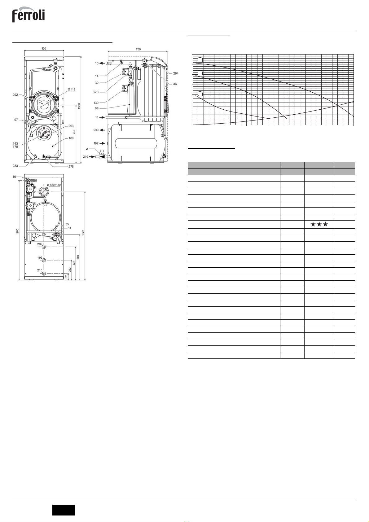
5.1 Dimensioni, attacchi e componenti principali
fig. 18 - Dimensionale, attacchi e componenti principali
A Valvola di sicurezza e antiritorno
10 Mandata impianto 3/4”
11 Ritorno impianto 1”
14 Valvola di sicurezza riscaldamento
32 Circolatore riscaldamento
36 Sfiato aria automatico
56 Vaso espansione
97 Anodo di magnesio
130 Circolatore bollitore
143 Termostato regolazione Bollitore
178 Bulbo termometro bollitore
180 Bollitore
192 Ricircolo
209 Mandata bollitore 3/4”
210 Ritorno bollitore 3/4”
233 Rubinetto scarico bollitore
275 Rubinetto di scarico impianto di riscaldamento
278 Sensore doppio (Sicurezza + riscaldamento)
292 Foro attacco bruciatore
293 Flangia di ispezione bollitore
294 Sensore di pressione impianto riscaldamento
5.2 Perdita di carico
Perdita di carico/Prevalenza circolatori
H [m H
O]
2
7
3
6
2
5
4
1
3
2
1
0
0 0.5 1 1.5 2
Q [m3/h]
2.5 3
fig. 19 - Perdite di carico
5.3 Tabella dati tecnici
Dato Unità Valo re
Modello D 30 K 100
Numero elementi n° 3
Portata termica max kW 32.2 (Q)
Portata termica min kW 16.9 (Q)
Potenza termica max riscaldamento kW 30 (P)
Potenza termica min riscaldamento kW 16 (P)
Rendimento Pmax (80-60°C) % 93.0
Rendimento 30% % 94.6
Classe efficienza direttiva 92/42 EEC
Pressione max esercizio riscaldamento bar 6 (PMS)
Pressione min esercizio riscaldamento bar 0.8
Temperatura max riscaldamento °C 95 tmax
Contenuto acqua riscaldamento l. 21
Capacità vaso di espansione riscaldamento l. 10
Pressione precarica vaso di espansione riscaldamento bar 1
Pressione max di esercizio sanitario bar 9 (PMW)
Pressione min di esercizio sanitario bar 0.1
Contenuto acqua sanitario l. 100
Capacità vaso di espansione sanitario l. 4
Portata sanitaria Dt 30°C l/10 min 220
Portata sanitaria Dt 30°C l/h 800
Grado protezione IP X0D
Tensione di alimentazione V/Hz 230/50
Potenza elettrica assorbita W 90
Potenza elettrica assorbita sanitario W 80
Peso a vuoto Kg 210
Lunghezza camera di combustione mm 350
Diametro camera di combustione mm 300
Perdita di carico lato fumi mbar 0.59
6
IT
cod. 3540S361 - 08/2009 (Rev. 00)
Page 7
ATLAS D 30 K 100
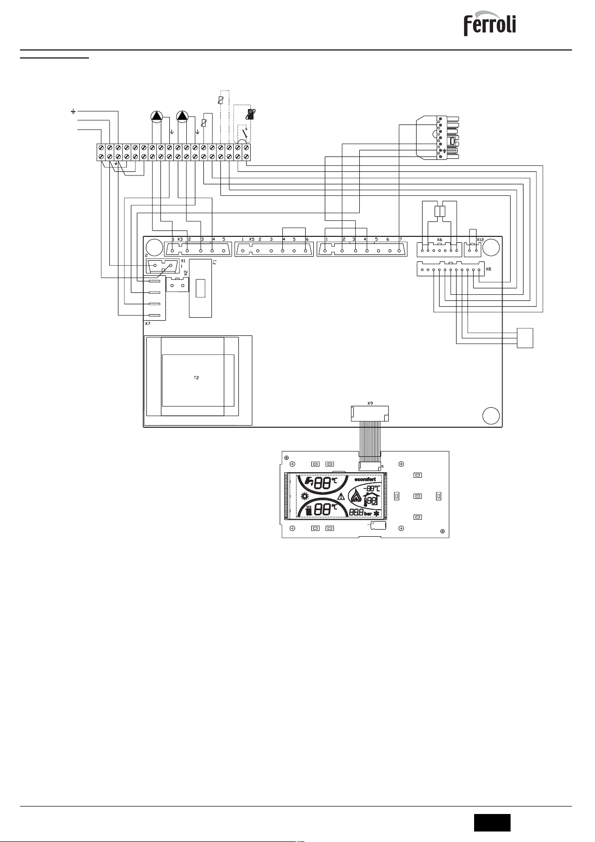
5.4 Schema elettrico
32
130
230V
N
50Hz
L
L
456789101112131415161718
N
138
42
139
72
211
T°T°
B4
S3
T2
T1
N
L1
278
fig. 20 - Schema elettrico
32 Circolatore riscaldamento
42 Sonda temperatura sanitario
72 Termoststo ambiente
130 Circolatore bollitore
138 Sonda esterna
139 Unità ambiente
211 Connettore bruciatore
246 Trasduttore di pressione
278 Sensore doppio (Sicurezza + riscaldamento)
DBM06
DSP05
246
OUT
+5V
GND
cod. 3540S361 - 08/2009 (Rev. 00)
IT
7
Page 8

ATLAS D 30 K 100
EN
1. GENERAL INSTRUCTIONS
• Carefully read the instructions contained in this instruction booklet.
• After boiler installation, inform the user regarding its operation and give him this manual, which is
an integral and essential part of the product and must be kept with care for future reference.
• Installation and maintenance must be carried out by professionally qualified personnel, according
to current regulations and the manufacturer's instructions. Do not carry out any operation on the
sealed control parts.
• Incorrect installation or inadequate maintenance can result in damage or injury. The Manufacturer
declines any liability for damage due to errors in installation and use or failure to follow the instructions.
• Before carrying out any cleaning or maintenance operation, disconnect the unit from the power
supply using the system switch and/or the special cut-off devices.
• In case of a fault and/or poor operation, deactivate the unit and do not attempt to repair it or directly
intervene. Contact professionally qualified personnel. Repair/replacement of the products must
only be carried out by professionally qualified using original spare parts. Failure to comply with the
above could affect the safety of the unit.
• This unit must only be used for its intended purpose. Any other use is considered improper and
therefore dangerous.
• The packing materials are potentially hazardous and must not be left within the reach of children.
• The images given in this manual are a simplified representation of the product. In this representation there may be slight and insignificant differences with respect to the product supplied.
2. OPERATING INSTRUCTIONS
2.1 Introduction
Dear Customer,
Thank you for choosing a FERROLI boiler featuring advanced design, cutting-edge tech-
nology, high reliability and quality construction. Please read this manual carefully since
it provides important information on safe installation, use and maintenance.
ATLAS D 30 K 100 is a high-efficiency heat generator for heating and domestic hot water
production, suitable for operating with oil or gas burners (blown). The boiler shell consists
of cast-iron elements, assembled with double cones and steel stays placed over a DHW
quick storage domestic hot water tank, vitrified, and protected against corrosion by a
magnesium anode. The control system is with microprocessor and digital interface with
advanced temperature control functions.
2.2 Control panel
12 1411
19
13
27
2426
fig. 1 - Control panel
Key
1 = DHW temperature setting decrease button
2 = DHW temperature setting increase button
3 = Heating system temperature setting decrease button
4 = Heating system temperature setting increase button
5 = Display
6 = Summer / Winter mode selection button
7 = Economy / Comfort mode selection button
8 = Reset button
9 = Unit On / Off button
10 = "Sliding Temperature" menu button
11 = Set DHW temperature reached
12 = DHW symbol
13 = DHW mode
14 = DHW outlet temperature / setting
15 = Eco (Economy) or Comfort mode
16 = External sensor temperature (with optional external probe)
17 = Appears on connecting the external Probe or the Remote Timer Control (op-
tionals)
18 = Room temperature (with optional Remote Timer Control)
19 = Burner On
20 = Antifreeze operation
21 = Heating system pressure
22 = Fault
23 = Heating delivery temperature / setting
24 = Heating symbol
25 = Heating mode
26 = Set heating delivery temperature reached
27 = Summer mode
15 16
ecomfort
bar
5791021
o
c
e
f
o
m
r
o
t
c
m
o
d
e
r
t
e
e
s
17182021222325
8643
Indication during operation
Heating
A heating demand (generated by the Room Thermostat or Remote Timer Control) is indicated by flashing of the hot air above the radiator (details 24 and 25 - fig. 1).
The heating graduation marks (detail 26 - fig. 1) light up as the heating sensor temperature reaches the set value.
o
c
e
f
m
o
r
o
t
eco
bar
c
m
o
d
e
r
t
e
e
s
fig. 2
DHW (Comfort)
A DHW demand (generated by drawing domestic hot water) is indicated by flashing of
the hot water under the tap (details 12 and 13 - fig. 1). Make sure the Comfort function
(detail 15 - fig. 1) is activated
The DHW graduation marks (detail 11 - fig. 1) light up as the DHW sensor temperature
reaches the set value.
o
c
e
f
m
o
r
o
t
comfort
bar
c
m
o
d
e
r
t
e
e
s
fig. 3
Hot water tank exclusion (economy)
Hot water storage tank temperature maintaining/heating can be excluded by the user. If
excluded, domestic hot water will not be delivered.
When hot water tank heating is activated (default setting), the COMFORT symbol (detail
15 - fig. 1) is activated on the display, and when off, the ECO symbol (detail 15 - fig. 1)
is activated on the display
The hot water tank can be deactivated by the user (ECO mode) by pressing the button
(detail 7 - fig. 1). To activate the COMFORT mode, press the button
(detail 7 - fig. 1) again.
2.3 Lighting and turning off
Boiler not electrically powered
o
c
e
f
m
o
r
o
t
c
m
o
d
e
r
t
e
e
s
fig. 4 - Boiler not electrically powered
The antifreeze system does not work when the power and/or gas to the unit are
turned off. To avoid damage caused by freezing during long idle periods in win-
B
ter, it is advisable to drain all water from the boiler, DHW circuit and system; or
drain just the DHW circuit and add a suitable antifreeze to the heating system,
complying with that prescribed in sec. 3.3.
Boiler lighting
• Open the fuel on-off valves.
• Switch on the power to the unit.
o
c
e
f
o
m
r
o
t
c
m
o
d
e
r
t
e
e
s
fig. 5 - Boiler lighting
• For the following 120 seconds the display will show FH which identifies the heating
system air venting cycle.
• During the first 5 seconds the display will also show the card software version.
• When the message FH disappears, the boiler is ready to operate automatically
whenever domestic hot water is drawn or in case of a room thermostat demand.
cod. 3540S361 - 08/2009 (Rev. 00)
EN
23
Page 9

ATLAS D 30 K 100
Turning the boiler off
Press the on/off button (detail 9 - fig. 1) for 1 second.
o
c
e
f
m
o
r
o
t
c
m
o
d
e
r
t
e
e
s
fig. 6 - Turning the boiler off
When the boiler is turned off, the PCB is still powered.
Domestic hot water and heating are disabled. The antifreeze system remains activated.
To relight the boiler, press the on/off button (detail 9 fig. 1) again for 1 second.
o
c
e
m
f
o
r
o
t
eco
bar
c
m
o
d
e
r
t
e
e
s
fig. 7
The boiler will be immediately ready to operate whenever domestic hot water is drawn
or in case of a room thermostat demand.
2.4 Adjustments
Summer/Winter Switchover
Press the summer/winter button (detail 6 - fig. 1) for 1 second.
o
c
e
f
m
o
r
o
t
eco
bar
c
m
o
d
e
r
t
e
e
s
Sliding Temperature
When the optional external probe is installed, the control panel display (detail 5 - fig. 1)
shows the actual outside temperature detected by the external probe. The boiler control
system operates with "Sliding Temperature". In this mode, the heating system temperature is controlled according to the outside weather conditions in order to ensure high
comfort and energy efficiency throughout the year. In particular, as the outside temperature increases the system delivery temperature decreases according to a specific "compensation curve".
With Sliding Temperature adjustment, the temperature set with the heating buttons
ture. It is advisable to set a maximum value to allow system adjustment throughout its
useful operating range.
(detail 3 and 4 - fig. 1) becomes the maximum system delivery tempera-
The boiler must be regulated at the time of installation by qualified personnel. Possible
adjustments can in any case be made by the user to improve comfort.
Compensation curve and curve offset
Press the mode button (detail 10 - fig. 1) once to display the compensation curve
(fig. 11) which can be modified with the DHW buttons (details 1 and 2 fig. 1).
Adjust the required curve from 1 to 10 according to the characteristic (fig. 13).
By setting the curve to 0, sliding temperature adjustment is disabled.
fig. 11 - Compensation curve
Press the heating buttons (details 3 and 4 - fig. 1) to access parallel curve
offset (fig. 14), modifiable with the DHW buttons (details 1 and 2 - fig. 1).
fig. 8
The display activates the Summer symbol (detail 27 - fig. 1): the boiler will only deliver
domestic hot water. The antifreeze system remains activated.
To deactivate the Summer mode, press the summer/winter button (part. 6 - fig. 1) again
for 1 second.
Heating temperature setting
Use the heating buttons (details 3 and 4 - fig. 1) to adjust the temperature
from a min. of 30°C to a max. of 90°C; it is inadvisable to operate the boiler below 45°C.
o
c
e
f
o
m
r
o
t
eco
bar
c
m
o
d
e
r
t
e
e
s
fig. 9
DHW temperature adjustment
Use the DHW buttons (details 1 and 2 - fig. 1) to adjust the temperature
from a min. of 10°C to a max. of 65°C.
o
c
e
f
m
o
r
o
t
eco
bar
c
m
o
d
e
r
t
e
e
s
fig. 10
Room temperature adjustment (with optional room thermostat)
Using the room thermostat, set the temperature desired in the rooms. If the room thermostat is not installed the boiler will keep the heating system at its setpoint temperature.
Room temperature adjustment (with optional remote timer control)
Using the remote timer control, set the temperature desired in the rooms. The boiler unit
will set the system water according to the required room temperature. For information on
the remote timer control, please refer to its user's manual.
fig. 12 - Curve parallel offset
Press the mode button (detail 10 - fig. 1) again to exit the parallel curve adjustment
mode.
If the room temperature is lower than the required value, it is advisable to set a higher
order curve and vice versa. Proceed by increasing or decreasing in steps of one and
check the result in the room.
90
85
80
70
60
50
40
30
20
20 10 0 -10 -20
68910 7
5
4
3
2
1
fig. 13 - Compensation curves
OFFSET = 20 OFFSET = 40
90
85
80
70
60
50
40
30
20
20 10 0 -10 -20
8910
7
6
5
4
3
2
1
90
85
80
70
60
50
40
30
20
20 10 0 -10 -20
568910 7
4
3
2
1
fig. 14 - Example of compensation parallel curve offset
24
EN
cod. 3540S361 - 08/2009 (Rev. 00)
Page 10

ATLAS D 30 K 100
Adjustments from Remote Timer Control
If the Remote Timer Control (optional) is connected to the boiler, the above ad-
A
justments are managed according to that given in table 1. Also, the control panel display (detail 5 - fig. 1) shows the actual room temperature detected by the
Remote Timer Control.
Table. 1
Heating temperature setting
DHW temperature adjustment
Summer/Winter Switchover
Eco/Comfort selection
Sliding Temperature
Water system pressure adjustment
The filling pressure with system cold, read on the display, must be approx. 1.0 bar. If the
system pressure falls to values below minimum, the boiler card will activate fault F37
(fig. 15).
Once the system pressure is restored, the boiler will activate the 120-second
A
air venting cycle indicated on the display by FH.
3. INSTALLATION
3.1 General Instructions
BOILER INSTALLATION MUST ONLY BE PERFORMED BY QUALIFIED PERSONNEL, IN ACCORDANCE WITH ALL THE INSTRUCTIONS GIVEN IN THIS TECHNICAL
MANUAL, THE PROVISIONS OF CURRENT LAW, THE PRESCRIPTIONS OF NATIONAL AND LOCAL STANDARDS AND THE RULES OF PROPER WORKMANSHIP.
3.2 Place of installation
The boiler must be installed in a special room with ventilation openings towards the outside in conformity with current regulations. If there are several burners or extraction units
that can work together in the same room, the ventilation openings must be sized for simultaneous operation of all the units. The place of installation must be free of flammable
objects or materials, corrosive gases, volatile substances or dusts which, sucked by the
burner fan, can obstruct the pipes inside the burner or the combustion head. The room
must be dry and not exposed to rain, snow or frost.
If the unit is enclosed in a cabinet or mounted alongside, a space must be pro-
A
vided for removing the casing and for normal maintenance operations. In particular, after boiler installation with burner on the front door, make sure the front
door can open freely without the burner striking walls or other obstacles.
3.3 Plumbing connections
The heating capacity of the unit must be previously established by calculating the building's heat requirement according to the current regulations. The system must be provided with all the components for correct and regular operation. It is advisable to install onoff valves between the boiler and heating system allowing the boiler to be isolated from
the system if necessary.
The safety valve outlet must be connected to a funnel or collection pipe to prevent water spurting onto the floor in case of overpressure in the heating circuit.
B
Otherwise, if the discharge valve cuts in and floods the room, the boiler manufacturer cannot be held liable.
Do not use the water system pipes to earth electrical appliances.
Before installation, carefully wash all the pipes of the system to remove any residuals or
impurities that could affect proper operation of the unit.
Carry out the relevant connections according to the diagram in cap. 5 and the symbols
given on the unit.
Install the safety and non-return valve (supplied with the boiler) on the cold water inlet.
B
Adjustment can be made from the Remote Timer Control menu and the boiler
control panel.
Adjustment can be made from the Remote Timer Control menu and the boiler
control panel.
Summer mode has priority over a possible Remote Timer Control heating
demand.
On disabling DHW from the Remote Timer Control menu, the boiler selects the
Economy mode. In this condition, the
abled.
On enabling DHW from the Remote Timer Control menu, the boiler selects the
Comfort mode. In this condition it is possible select one of the two modes with
the
button 7
- fig. 1 on the boiler panel.
Both the Remote Timer Control and the boiler card manage Sliding Temperature adjustment: of the two, the Sliding Temperature of the boiler card has priority.
fig. 15 - Low system pressure fault
button 7
- fig. 1 on the boiler panel is dis-
Water system characteristics
In the presence of water harder than 25° Fr (1°F = 10ppm CaCO3), use suitably treated
water in order to avoid possible scaling in the boiler. Treatment must not reduce the hardness to values below 15°F (Decree 236/88 for uses of water intended for human consumption). Treatment of the water used is indispensable in case of very large systems
or with frequent introduction of replenishing water in the system.
If water softeners are installed at the boiler cold water inlet, make sure not to
reduce the water hardness too much, as this could cause early deterioration of
B
the magnesium anode in the hot water tank.
Antifreeze system, antifreeze fluids, additives and inhibitors
The boiler is equipped with an antifreeze system that turns on the boiler in heating mode
when the system delivery water temperature falls under 6°C. The device will not come
on if the electricity and/or gas supply to the unit are cut off. If it becomes necessary, it is
permissible to use antifreeze fluid, additives and inhibitors only if the manufacturer of
these fluids or additives guarantees they are suitable for this use and cause no damage
to the heat exchanger or other components and/or materials of the boiler unit and system. It is prohibited to use generic antifreeze fluid, additives or inhibitors that are not expressly suited for use in heating systems and compatible with the materials of the boiler
unit and system.
3.4 Burner connection
An oil or gas burner, with blown air for pressured furnaces, can be used if its operation
characteristics are suitable for the size of the boiler furnace and its overpressure. The
choice of burner must be made beforehand, following the manufacturer's instructions,
according to the work range, fuel consumption and pressures, as well as the length of
the firebox. Install the burner in compliance with the Manufacturer's instructions.
3.5 Electrical connections
Connection to the electrical grid
The unit's electrical safety is only guaranteed when correctly connected to an
efficient earthing system executed according to current safety standards. Have
B
the efficiency and suitability of the earthing system checked by professionally
qualified personnel. The manufacturer is not responsible for any damage
caused by failure to earth the system. Also make sure that the electrical system
is adequate for the maximum power absorbed by the unit, as specified on the
boiler dataplate.
The boiler is prewired and provided with a Y-cable and plug for connection to the electricity line. The connections to the grid must be made with a permanent connection and
equipped with a bipolar switch whose contacts have a minimum opening of at least 3
mm, interposing fuses of max. 3A between the boiler and the line. It is important to respect the polarities (LINE: brown wire / NEUTRAL: blue wire / EARTH: yellow-green
wire) in making connections to the electrical line. During installation or when changing
the power cable, the earth wire must be left 2 cm longer than the others.
The user must never change the unit's power cable. If the cable gets damaged,
switch off the unit and have it changed solely by professionally qualified person-
B
nel. If changing the electric power cable, use solely “HAR H05 VV-F” 3x0.75
mm2 cable with a maximum outside diameter of 8 mm.
Room thermostat (optional)
IMPORTANT: THE ROOM THERMOSTAT MUST HAVE VOLTAGE-FREE
CONTACTS. CONNECTING 230 V TO THE ROOM THERMOSTAT TERMI-
B
NALS WILL PERMANENTLY DAMAGE THE ELECTRONIC BOARD.
When connecting time controls or a timer, do not take the power supply for
these devices from their breaking contacts Their power supply must be by
means of direct connection from the mains or with batteries, depending on the
kind of device.
Accessing the electrical terminal block
Undo the two screws “A” located on the top part of the control panel and remove the
cover.
A
fig. 16 - Accessing the terminal board
3.6 Connection to the flue
The unit must be connected to a flue designed and built in compliance with current regulations. The pipe between the boiler and flue must be made from material suitable for
the purpose, i.e. heat and corrosion resistant. Ensure the seal at the joints and insulate
the entire pipe between boiler and flue, to prevent the formation of condensate.
cod. 3540S361 - 08/2009 (Rev. 00)
EN
25
Page 11

ATLAS D 30 K 100
4. SERVICE AND MAINTENANCE
All adjustment, conversion, commissioning and maintenance operations described below must only be carried out by Qualified Personnel (meeting the professional technical
requirements prescribed by current regulations) such as those of the Local After-Sales
Technical Service.
FERROLI declines any liability for damage and/or injury caused by unqualified and unauthorised persons tampering with the unit.
4.1 Adjustments
TEST mode activation
Press the heating buttons (details 3 and 4 - ) together for 5 seconds to activate the fig. 1TEST mode. The boiler lights at maximum power.
The heating symbol (detail 24 - fig. 1) and DHW symbol (detail 12 - fig. 1) flash on the
display.
o
c
e
f
o
m
r
o
t
eco
bar
c
m
o
d
e
r
t
e
e
s
fig. 17 - TEST mode
To deactivate the TEST mode, repeat the activation sequence.
The TEST mode is automatically disabled in any case after 15 minutes.
Burner adjustment
Boiler efficiency and correct operation depend above all on accurate burner adjustments.
Carefully follow the Manufacturer's instructions. The two-stage burners must have the
first stage adjusted to a power level not below the boiler's rated min. power. The power
of the second stage must not be higher than the boiler's rated max. power.
4.2 Start-up
Checks to be made at first lighting, and after all maintenance operations that
involved disconnecting from the systems or an intervention on safety devices
B
or parts of the boiler:
Before lighting the boiler
• Open any on-off valves between the boiler and the systems.
• Check the seal of the fuel system.
• Check correct prefilling of the expansion tank.
• Fill the water system and make sure that all air contained in the boiler and the system has been vented, by opening the air valve on the boiler and any air valves on
the system.
• Make sure there are no water leaks in the system, domestic hot water circuits, connections or boiler.
• Check correct connection of the electrical system and efficiency of the earthing system
• Make sure there are no flammable liquids or materials in the immediate vicinity of
the boiler
Checks during operation
• Turn the unit on as described in sec. 2.3.
• Check the seal of the fuel circuit and water systems.
• Check the efficiency of the flue and air-fume ducts during boiler operation.
• Make sure the water is circulating properly between the boiler and systems.
• Check correct boiler lighting by performing various tests, turning it on and off with
the room thermostat or remote control.
• Make sure the fuel consumption indicated on the meter matches that given in the
technical data table on sec. 5.3.
• Ensure the seal of the fumebox and burner door.
• Make sure the burner works properly. This check must be made with the special instruments, following the manufacturer's instructions.
• Check correct programming of the parameters and carry out any required customisation (compensation curve, power, temperatures, etc.).
4.3 Maintenance
Periodical check
To ensure correct operation of the unit over time, have qualified personnel carry out a
yearly check, providing for the following:
• The control and safety devices must function correctly.
• The fume exhaust circuit must be perfectly efficient.
• Check there are no obstructions or dents in the fuel supply and return pipes.
• Clean the filter of the fuel suction line.
• Measure the correct fuel consumption
• Clean the combustion head in the fuel outlet zone, on the swirl disc.
• Leave the burner running at full rate for approximately ten minutes, then analyse
the combustion, checking:
- All the elements specified in this manual are set correctly
- Temperatures of the fumes at the flue
- CO2 percentage content
• The air-fume end piece and ducts must be free of obstructions and leaks
• The burner and exchanger must be clean and free of deposits. For possible cleaning do not use chemical products or wire brushes.
• The gas and water systems must be airtight.
• The water pressure in the cold water system must be approx. 1 bar; otherwise, bring
it to that value.
• The circulating pump must not be blocked.
• The expansion tank must be filled.
• Check the magnesium anode and replace it if necessary.
The boiler casing, control panel and aesthetic parts can be cleaned with a soft
A
and damp cloth, if necessary soaked in soapy water. Do not use any abrasive
detergents and solvents.
Boiler cleaning
1. Disconnect the power supply to the boiler.
2. Remove the front top and bottom panel.
3. Open the door by undoing the knobs.
4. Clean the inside of the boiler and the entire path of exhaust fumes, using a tube
brush or compressed air.
5. Then close the door, securing it with the knob.
To clean the burner, refer to the Manufacturer's instructions.
4.4 Troubleshooting
Diagnostics
The boiler is equipped with an advanced self-diagnosis system. In case of a boiler fault,
the display will flash together with the fault symbol (detail 22 - fig. 1) indicating the fault
code.
Some faults cause permanent shutdown (marked with the letter "A"): to restore operation, press the RESET button (detail 8 - fig. 1) for 1 second or RESET on the optional
remote timer control if installed; if the boiler fails to restart, it is necessary to eliminate the
fault indicated by the operation LED's.
other faults (indicated with the letter "F") cause temporary shutdowns which are automatically reset as soon as the value returns within the boiler's normal operation range.
Table. 2 - List of faults
Fault
Fault Possible cause Cure
code
Burner block
(RESET ONLY
A01
OCCURS ON THE
BURNER)
Overtemperature protec-
A03
tion activation
F07
Wiring fault Connector X5 not connected Check the wiring
F10
Delivery sensor 1 fault
F11
DHW sensor fault
F13
Wiring fault
F14
Delivery sensor 2 fault
Supply voltage under
F34
170V.
F35
Faulty mains frequency Electric mains trouble Check the electrical system
Incorrect system water
F37
pressure
F39
External probe fault
Incorrect system water
F40
pressure
A41
Sensor positioning
F42
Heating sensor fault Sensor damaged Replace the sensor
System water pressure
F47
sensor fault
Refer to the burner manual
Heating sensor damaged
No water circulation in the
system
Air in the system Vent the system
Sensor damaged
Wiring disconnected
Sensor damaged
Wiring disconnected
Connector X12 not con-
nected
Sensor damaged
Wiring disconnected
Electric mains trouble Check the electrical system
Pressure too low Fill the system
Sensor damaged Check the sensor
Probe damaged or wiring
shorted
Sensor disconnected after
activating the sliding temperature
Pressure too high
Delivery sensor not inserted
in boiler shell
Wiring disconnected Check the wiring
Check the correct positioning and operation
of the heating sensor
Check the circulating pump
Check the wiring or replace the sensorWiring shorted
Check the wiring or replace the sensorWiring shorted
Check the wiring
Check the wiring or replace the sensorWiring shorted
Check the wiring or replace the sensor
Reconnect the external probe or disable the
sliding temperature
Check the system
Check the safety valve
Check the expansion tank
Check the correct positioning and operation
of the heating sensor
26
EN
cod. 3540S361 - 08/2009 (Rev. 00)
Page 12

ATLAS D 30 K 100
5. TECHNICAL DATA AND CHARACTERISTICS
5.1 Dimensions, connections and main components
fig. 18 - Dimensions, connections and main components
A Safety and non-return valve
10 System delivery 3/4”
11 System return 1”
14 Heating safety valve
32 Heating circulating pump
36 Automatic air vent
56 Expansion tank
97 Magnesium anode
130 Hot water tank circulating pump
143 Hot water tank control thermostat
178 Hot water tank thermometer bulb
180 Hot water tank
192 Recirculation
209 Hot water tank delivery 3/4”
210 Hot water tank return 3/4”
233 Hot water tank drain cock
275 Heating system drain cock
278 Double sensor (Safety + Heating)
292 Burner connection hole
293 Hot water tank inspection flange
294 Heating system pressure sensor
5.2 Pressure loss
Circulating pumps Head/Pressure loss
H [m H
O]
2
7
3
6
2
5
4
1
3
2
1
0
0 0.5 1 1.5 2
Q [m3/h]
2.5 3
fig. 19 - Pressure losses
5.3 Technical data table
Data Unit Valu e
Model D 30 K 100
Number of elements no. 3
Max. heating capacity kW 32.2 (Q)
Min. heating capacity kW 16.9 (Q)
Max. heat output in heating kW 30 (P)
Min. heat output in heating kW 16 (P)
Efficiency Pmax (80-60°C) % 93.0
Efficiency 30% % 94.6
Efficiency class Directive 92/42 EEC
Max. working pressure in heating bar 6 (PMS)
Min. working pressure in heating bar 0.8
Max. heating temperature °C 95 tmax
Heating water content L 21
Heating expansion tank capacity L 10
Heating expansion tank prefilling pressure bar 1
Max. working pressure in hot water production bar 9 (PMW)
Min. working pressure in hot water production bar 0.1
Hot water content L 100
Hot water expansion tank capacity L 4
DHW flowrate Dt 30°C l/10 min 220
DHW flowrate Dt 30°C l/h 800
Protection rating IP X0D
Power supply voltage V/Hz 230/50
Electrical power input W 90
Electrical power input in hot water production W 80
Empty weight kg 210
Combustion chamber length mm 350
Combustion chamber diameter mm 300
Pressure loss on fume side mbar 0.59
cod. 3540S361 - 08/2009 (Rev. 00)
EN
27
Page 13

ATLAS D 30 K 100
5.4 Wiring diagram
230V
N
50Hz
L
32
130
L
456789101112131415161718
N
138
42
139
72
DBM06
211
T°T°
B4
S3
T2
T1
N
L1
278
246
OUT
+5V
GND
fig. 20 - Wiring diagram
32 Heating circulating pump
42 DHW temperature probe
72 Room thermostat
130 Hot water tank circulating pump
138 External probe
139 Room unit
211 Burner connector
246 Pressure transducer
278 Double sensor (Safety + Heating)
DSP05
28
EN
cod. 3540S361 - 08/2009 (Rev. 00)
Page 14

ATLAS D 30 K 100
RU
1. ɈȻɓɂȿ ɍɄȺɁȺɇɂʇ ɉɈ ɌȿɏɇɂɄȿ ȻȿɁɈɉȺɋɇɈɋɌɂ
• ȼɧɢɦɚɬɟɥɶɧɨ ɩɪɨɱɢɬɚɣɬɟ ɩɪɟɞɭɩɪɟɠɞɟɧɢɹ, ɫɨɞɟɪɠɚɳɢɟɫɹ ɜ ɧɚɫɬɨɹɳɟɦ ɪɭɤɨɜɨɞɫɬɜɟ.
• ɉɨɫɥɟ ɭɫɬɚɧɨɜɤɢ ɤɨɬɥɚ ɩɪɨɢɧɮɨɪɦɢɪɭɣɬɟ ɩɨɥɶɡɨɜɚɬɟɥɹ ɨ ɩɪɢɧɰɢɩɚɯ ɪɚɛɨɬɵ ɚɝɪɟɝɚɬɚ ɢ ɩɟɪɟɞɚɣɬɟ
ɟɦɭ ɧɚɫɬɨɹɳɟɟ ɪɭɤɨɜɨɞɫɬɜɨ; ɨɧɨ ɹɜɥɹɟɬɫɹ ɫɭɳɟɫɬɜɟɧɧɨɣ ɢ ɧɟɨɬɴɟɦɥɟɦɨɣ ɱɚɫɬɶɸ ɢɡɞɟɥɢɹ ɢ ɞɨɥɠɧɨ
ɛɟɪɟɠɧɨ ɫɨɯɪɚɧɹɬɶɫɹ ɞɥɹ ɢɫɩɨɥɶɡɨɜɚɧɢɹ ɜ ɛɭɞɭɳɟɦ.
• ɍɫɬɚɧɨɜɤɚ ɢ ɬɟɯɧɢɱɟɫɤɨɟ ɨɛɫɥɭɠɢɜɚɧɢɟ ɤɨɬɥɚ ɞɨɥɠɧɵ ɩɪɨɢɡɜɨɞɢɬɶɫɹ ɤɜɚɥɢɮɢɰɢɪɨɜɚɧɧɵɦ
ɩɟɪɫɨɧɚɥɨɦ ɩɪɢ ɫɨɛɥɸɞɟɧɢɢ ɞɟɣɫɬɜɭɸɳɢɯ ɧɨɪɦ ɢ ɜ ɫɨɨɬɜɟɬɫɬɜɢɢ ɫ ɭɤɚɡɚɧɢɹɦɢ ɢɡɝɨɬɨɜɢɬɟɥɹ.
Ɂɚɩɪɟɳɚɟɬɫɹ ɜɵɩɨɥɧɹɬɶ ɤɚɤɢɟ-ɥɢɛɨ ɪɚɛɨɬɵ ɧɚ ɨɩɥɨɦɛɢɪɨɜɚɧɧɵɯ ɪɟɝɭɥɢɪɨɜɨɱɧɵɯ ɭɫɬɪɨɣɫɬɜɚɯ.
• ɇɟɩɪɚɜɢɥɶɧɚɹ ɭɫɬɚɧɨɜɤɚ ɢɥɢ ɧɟɧɚɞɥɟɠɚɳɟɟ ɬɟɯɧɢɱɟɫɤɨɟ ɨɛɫɥɭɠɢɜɚɧɢɟ ɦɨɝɭɬɩɪɢɜɟɫɬɢɤ
ɦɚɬɟɪɢɚɥɶɧɨɦɭ ɭɳɟɪɛɭ ɢɥɢ ɬɪɚɜɦɚɦ ɥɸɞɟɣ ɢ ɠɢɜɨɬɧɵɯ. ɂɡɝɨɬɨɜɢɬɟɥɶ ɧɟ ɧɟɫɟɬ ɧɢɤɚɤɨɣ
ɨɬɜɟɬɫɬɜɟɧɧɨɫɬɢ ɡɚ ɭɳɟɪɛ, ɫɜɹɡɚɧɧɵɣ ɫ ɨɲɢɛɨɱɧɵɦɢ ɭɫɬɚɧɨɜɤɨɣ ɢ ɷɤɫɩɥɭɚɬɚɰɢɟɣ ɚɩɩɚɪɚɬɚ, ɚ ɬɚɤɠɟ
ɫ ɧɟɫɨɛɥɸɞɟɧɢɟɦ ɩɪɟɞɨɫɬɚɜɥɟɧɧɵɯ ɢɦ ɢɧɫɬɪɭɤɰɢɣ.
• ɉɟɪɟɞ ɜɵɩɨɥɧɟɧɢɟɦ ɥɸɛɨɣ ɨɩɟɪɚɰɢɢ ɩɨ ɱɢɫɬɤɟ ɢɥɢ ɬɟɯɧɢɱɟɫɤɨɦɭ ɨɛɫɥɭɠɢɜɚɧɢɸɨɬɫɨɟɞɢɧɢɬɟɚɝɪɟɝɚɬ
ɨɬ ɫɟɬɢ ɷɥɟɤɬɪɨɩɢɬɚɧɢɹ ɫ ɩɨɦɨɳɶɸ ɝɥɚɜɧɨɝɨ ɪɭɛɢɥɶɧɢɤɚ ɢ/ɢɥɢ ɩɪɟɞɭɫɦɨɬɪɟɧɧɵɯ ɞɥɹ ɷɬɨɣ ɰɟɥɢ
ɨɬɫɟɱɧɵɯ ɭɫɬɪɨɣɫɬɜ.
• ȼ ɫɥɭɱɚɟ ɧɟɢɫɩɪɚɜɧɨɣ ɢ/ɢɥɢ ɧɟɧɨɪɦɚɥɶɧɨɣ ɪɚɛɨɬɵ ɚɝɪɟɝɚɬɚ, ɜɵɤɥɸɱɢɬɟ ɟɝɨ ɢ ɜɨɡɞɟɪɠɢɬɟɫɶ ɨɬ ɥɸɛɨɣ
ɩɨɩɵɬɤɢ ɫɚɦɨɫɬɨɹɬɟɥɶɧɨ ɨɬɪɟɦɨɧɬɢɪɨɜɚɬɶ ɢɥɢ ɭɫɬɪɚɧɢɬɶ ɩɪɢɱɢɧɭ ɧɟɢɫɩɪɚɜɧɨɫɬɢ. ȼ ɬɚɤɢɯ ɫɥɭɱɚɹɯ
ɨɛɪɚɳɚɣɬɟɫɶ ɢɫɤɥɸɱɢɬɟɥɶɧɨ ɤ ɤɜɚɥɢɮɢɰɢɪɨɜɚɧɧɵɦ ɫɩɟɰɢɚɥɢɫɬɚɦ. ȼɨɡɦɨɠɧɵɟ ɨɩɟɪɚɰɢɢ ɩɨ
ɪɟɦɨɧɬɭ-ɡɚɦɟɧɟ ɤɨɦɩɥɟɤɬɭɸɳɢɯ ɞɨɥɠɧɵ ɜɵɩɨɥɧɹɬɶɫɹ ɬɨɥɶɤɨ ɤɜɚɥɢɮɢɰɢɪɨɜɚɧɧɵɦɢ ɫɩɟɰɢɚɥɢɫɬɚɦɢ
ɫ ɢɫɩɨɥɶɡɨɜɚɧɢɟɦ ɢɫɤɥɸɱɢɬɟɥɶɧɨ ɨɪɢɝɢɧɚɥɶɧɵɯ ɡɚɩɱɚɫɬɟɣ. ɇɟɫɨɛɥɸɞɟɧɢɟ ɜɫɟɝɨ ɜɵɲɟɭɤɚɡɚɧɧɨɝɨ
ɦɨɠɟɬ ɧɚɪɭɲɢɬɶ ɛɟɡɨɩɚɫɧɨɫɬɶ ɪɚɛɨɬɵ ɚɝɪɟɝɚɬɚ.
• ɇɚɫɬɨɹɳɢɣ ɚɝɪɟɝɚɬ ɫɥɟɞɭɟɬ ɢɫɩɨɥɶɡɨɜɚɬɶ ɬɨɥɶɤɨ ɩɨ ɩɪɟɞɭɫɦɨɬɪɟɧɧɨɦɭ ɧɚɡɧɚɱɟɧɢɸ. Ʌɸɛɨɟ ɩɪɨɱɟɟ
ɢɫɩɨɥɶɡɨɜɚɧɢɟ ɫɥɟɞɭɟɬ ɫɱɢɬɚɬɶ ɧɟɩɪɚɜɢɥɶɧɵɦ ɢ, ɫɥɟɞɨɜɚɬɟɥɶɧɨ, ɩɪɟɞɫɬɚɜɥɹɸɳɢɦ ɨɩɚɫɧɨɫɬɶ.
• ɍɩɚɤɨɜɨɱɧɵɟ ɦɚɬɟɪɢɚɥɵ ɹɜɥɹɸɬɫɹ ɢɫɬɨɱɧɢɤɨɦ ɩɨɬɟɧɰɢɚɥɶɧɨɣ ɨɩɚɫɧɨɫɬɢ ɢ ɧɟ ɞɨɥɠɧɵ ɛɵɬɶ
ɨɫɬɚɜɥɟɧɵ ɜ ɦɟɫɬɚɯ, ɞɨɫɬɭɩɧɵɯ ɞɟɬɹɦ.
• ɉɪɢɜɟɞɟɧɧɵɟ ɜ ɧɚɫɬɨɹɳɟɦ ɪɭɤɨɜɨɞɫɬɜɟ ɢɡɨɛɪɚɠɟɧɢɹ ɞɚɸɬ ɭɩɪɨɳɟɧɧɨɟ ɩɪɟɞɫɬɚɜɥɟɧɢɟ ɨɛ ɚɝɪɟɝɚɬɟ ɢ
ɦɨɝɭɬ ɫɨɞɟɪɠɚɬɶ ɧɟɫɭɳɟɫɬɜɟɧɧɵɟ ɨɬɥɢɱɢɹ ɨɬ ɩɨɫɬɚɜɥɟɧɧɨɝɨ ɢɡɞɟɥɢɹ.
2. ɂɇɋɌɊɍɄɐɂɂ ɉɈ ɗɄɋɉɅɍȺɌȺɐɂɂ
2.1 ɉɪɟɞɢɫɥɨɜɢɟ
ɍɜɚɠɚɟɦɵɣ ɩɨɤɭɩɚɬɟɥɶ,
Ȼɥɚɝɨɞɚɪɢɦ ȼɚɫ ɡɚ ɬɨ, ɱɬɨ ȼɵ ɜɵɛɪɚɥɢ ɤɨɬɟɥ
ɤɨɧɫɬɪɭɤɰɢɸ, ɜɵɩɨɥɧɟɧɧɵɣ ɩɨ ɩɟɪɟɞɨɜɵɦ ɬɟɯɧɨɥɨɝɢɹɦ ɢ ɨɬɥɢɱɚɸɳɢɣɫɹ ɜɵɫɨɤɨɣ
ɧɚɞɟɠɧɨɫɬɶɸ ɢ ɤɚɱɟɫɬɜɨɦ. ɉɪɨɫɢɦ ȼɚɫ ɜɧɢɦɚɬɟɥɶɧɨ ɩɪɨɱɢɬɚɬɶ ɧɚɫɬɨɹɳɟɟ ɪɭɤɨɜɨɞɫɬɜɨ, ɬ.ɤ.
ɜ ɧɟɦ ɩɪɢɜɨɞɹɬɫɹ ɜɚɠɧɵɟ ɭɤɚɡɚɧɢɹ ɩɨ ɛɟɡɨɩɚɫɧɨɫɬɢ ɭɫɬɚɧɨɜɤɢ, ɷɤɫɩɥɭɚɬɚɰɢɢ ɢ
ɬɟɯɧɢɱɟɫɤɨɝɨ ɨɛɫɥɭɠɢɜɚɧɢɹ ɚɝɪɟɝɚɬɚ.
ATLAS D 30 K 100
ɤɨɬɨɪɨɦ ɦɨɝɭɬ ɛɵɬɶ ɢɫɩɨɥɶɡɨɜɚɧɵ ɠɢɞɤɨɬɨɩɥɢɜɧɵɟ ɢɥɢ ɝɚɡɨɜɵɟ ɝɨɪɟɥɨɱɧɵɟ ɭɫɬɪɨɣɫɬɜɚ ɫ
ɩɨɞɞɭɜɨɦ. Ʉɨɪɩɭɫ ɤɨɬɥɚ ɫɨɛɪɚɧ ɢɡ ɱɭɝɭɧɧɵɯ ɷɥɟɦɟɧɬɨɜ, ɫɨɟɞɢɧɟɧɧɵɯ ɦɟɠɞɭ ɫɨɛɨɣ
ɞɜɭɯɤɨɧɭɫɧɵɦɢ ɤɨɥɶɰɚɦɢ ɢ ɫɬɹɠɧɵɦɢ ɛɨɥɬɚɦɢ ɢɡ ɫɬɚɥɢ. Ⱦɚɧɧɵɟ ɷɥɟɦɟɧɬɵ ɭɫɬɚɧɨɜɥɟɧɵ
ɧɚɞ ɛɨɣɥɟɪɨɦ ɛɵɫɬɪɨɝɨ ɧɚɤɨɩɥɟɧɢɹ ɢɡ ɫɬɚɥɢ ɫɨ ɫɬɟɤɥɹɧɧɵɦ ɩɨɤɪɵɬɢɟɦ, ɩɪɟɞɧɚɡɧɚɱɟɧɧɵɦ
ɞɥɹ ɩɪɢɝɨɬɨɜɥɟɧɢɹ ɜɨɞɵ ɞɥɹ Ƚȼɋ. Ȼɨɣɥɟɪ ɡɚɳɢɳɟɧ ɨɬ ɤɨɪɪɨɡɢɢ ɦɚɝɧɢɟɜɵɦ ɚɧɨɞɨɦ.
Ʉɨɧɬɪɨɥɶ ɢ ɭɩɪɚɜɥɟɧɢɟ ɤɨɬɥɨɦ ɨɛɟɫɩɟɱɢɜɚɟɬ ɦɢɤɪɨɩɪɨɰɟɫɫɨɪ ɫ ɰɢɮɪɨɜɵɦ ɢɧɬɟɪɮɟɣɫɨɦ,
Ʉɨɬɟɥ ɩɪɟɞɫɬɚɜɥɹɟɬ ɫɨɛɨɣ ɬɟɩɥɨɜɨɣ ɝɟɧɟɪɚɬɨɪ ɞɥɹ ɨɬɨɩɥɟɧɢɹ ɢ Ƚȼɋ, ɜ
ɩɪɟɞɨɫɬɚɜɥɹɸɳɢɦ ɩɟɪɟɞɨɜɵɟ ɮɭɧɤɰɢɢ ɪɟɝɭɥɢɪɨɜɚɧɢɹ ɬɟɦɩɟɪɚɬɭɪɵ.
2.2 ɉɚɧɟɥɶ ɭɩɪɚɜɥɟɧɢɹ
12 1411
13
27
2426
ɪɢɫ.1 - ɉɚɧɟɥɶ ɭɩɪɚɜɥɟɧɢɹ
Ɉɛɨɡɧɚɱɟɧɢɹ
1 =
Ʉɥɚɜɢɲɚ ɭɦɟɧɶɲɟɧɢɹ ɬɟɦɩɟɪɚɬɭɪɵ ɜɨɞɵ Ƚȼɋ
2 =
Ʉɥɚɜɢɲɚ ɭɜɟɥɢɱɟɧɢɹ ɬɟɦɩɟɪɚɬɭɪɵ ɜɨɞɵ Ƚȼɋ
3 =
Ʉɥɚɜɢɲɚ ɭɦɟɧɶɲɟɧɢɹ ɬɟɦɩɟɪɚɬɭɪɵ ɜɨɞɵ ɜ ɫɢɫɬɟɦɟ ɨɬɨɩɥɟɧɢɹ
4 =
Ʉɥɚɜɢɲɚ ɭɜɟɥɢɱɟɧɢɹ ɬɟɦɩɟɪɚɬɭɪɵ ɜɨɞɵ ɜ ɫɢɫɬɟɦɟ ɨɬɨɩɥɟɧɢɹ
5 =
Ⱦɢɫɩɥɟɣ
6 =
Ʉɥɚɜɢɲɚ ɜɵɛɨɪɚ ɪɟɠɢɦɚ Ʌɟɬɨ/Ɂɢɦɚ
7 =
Ʉɥɚɜɢɲɚ ɜɵɛɨɪɚ ɪɟɠɢɦɚ Economy/Comfort
8 =
Ʉɥɚɜɢɲɚ ɋɛɪɨɫ
9 =
Ʉɥɚɜɢɲɚ ɜɤɥɸɱɟɧɢɹ/ɜɵɤɥɸɱɟɧɢɹ
10 =
Ʉɥɚɜɢɲɚ ɦɟɧɸ "ɉɥɚɜɚɸɳɚɹ ɬɟɦɩɟɪɚɬɭɪɚ"
11 =
ɂɧɞɢɤɚɬɨɪ ɞɨɫɬɢɠɟɧɢɹ ɡɚɞɚɧɧɨɣ ɬɟɦɩɟɪɚɬɭɪɵ ɜɨɞɵ Ƚȼɋ
12 =
ɋɢɦɜɨɥ Ƚȼɋ
13 =
ɋɢɦɜɨɥ ɪɚɛɨɬɵ ɚɝɪɟɝɚɬɚ ɜ ɪɟɠɢɦɟ Ƚȼɋ
14 =
Ɂɚɞɚɧɢɟ / Ɍɟɦɩɟɪɚɬɭɪɚ ɜɨɞɵ ɜ ɤɨɧɬɭɪɟ ɝɨɪɹɱɟɝɨ ɜɨɞɨɫɧɚɛɠɟɧɢɹ
15 =
ɂɧɞɢɤɚɰɢɹ ɪɚɛɨɬɵ ɚɝɪɟɝɚɬɚ ɜ ɪɟɠɢɦɟ Eco (Economy) ɢɥɢ Comfort
16 =
ɂɧɞɢɤɚɰɢɹ ɜɧɟɲɧɟɣ ɬɟɦɩɟɪɚɬɭɪɵ (ɩɪɢ ɧɚɥɢɱɢɢ ɨɩɰɢɨɧɧɨɝɨ ɜɧɟɲɧɟɝɨ ɞɚɬɱɢɤɚ)
17 =
ɉɨɹɜɥɹɟɬɫɹ ɩɪɢ ɩɨɞɤɥɸɱɟɧɢɢ ɜɧɟɲɧɟɝɨ ɞɚɬɱɢɤɚ ɢɥɢ ɭɫɬɪɨɣɫɬɜɚ Ⱦɍ ɫ ɬɚɣɦɟɪɨɦ
(ɨɩɰɢɢ)
18 =
Ɍɟɦɩɟɪɚɬɭɪɚ ɜɨɡɞɭɯɚ ɜ ɩɨɦɟɳɟɧɢɢ (ɩɪɢ ɧɚɥɢɱɢɢ ɨɩɰɢɨɧɧɨɝɨ ɭɫɬɪɨɣɫɬɜɚ Ⱦɍ ɫ
ɬɚɣɦɟɪɨɦ)
19 =
ɋɢɦɜɨɥ "ɉɥɚɦɹ"
20 =
ɋɢɦɜɨɥ ɪɚɛɨɬɵ ɫɢɫɬɟɦɵ ɡɚɳɢɬɵ ɨɬ ɡɚɦɟɪɡɚɧɢɹ
21 =
ɂɧɞɢɤɚɰɢɹ ɞɚɜɥɟɧɢɹ ɜ ɤɨɧɬɭɪɟ ɨɬɨɩɥɟɧɢɹ
22 =
ɂɧɞɢɤɚɰɢɹ ɧɟɢɫɩɪɚɜɧɨɫɬɢ
23 =
Ɂɚɞɚɧɢɟ / ɬɟɦɩɟɪɚɬɭɪɚ ɜ ɩɨɞɚɸɳɟɦ ɤɨɧɬɭɪɟ ɫɢɫɬɟɦɵ ɨɬɨɩɥɟɧɢɹ
24 =
ɋɢɦɜɨɥ ɨɬɨɩɥɟɧɢɹ
25 =
ɂɧɞɢɤɚɰɢɹ ɪɚɛɨɬɵ ɚɝɪɟɝɚɬɚ ɜ ɪɟɠɢɦɟ ɨɬɨɩɥɟɧɢɹ
19
ecomfort
FERROLI
5791021
15 16
bar
, ɢɦɟɸɳɢɣ ɫɚɦɭɸ ɫɨɜɪɟɦɟɧɧɭɸ
o
c
e
f
o
m
r
o
t
c
m
o
d
e
r
t
e
e
s
17182021222325
8643
26 =
ɂɧɞɢɤɚɰɢɹ ɞɨɫɬɢɠɟɧɢɹ ɡɚɞɚɧɧɨɣ ɬɟɦɩɟɪɚɬɭɪɵ ɜ ɫɢɫɬɟɦɟ ɨɬɨɩɥɟɧɢɹ
27 =
ɂɧɞɢɤɚɰɢɹ "Ʌɟɬɧɢɣ ɪɟɠɢɦ"
ɂɧɞɢɤɚɰɢɹ ɜɨ ɜɪɟɦɹ ɪɚɛɨɬɵ ɤɨɬɥɚ
Ɋɟɠɢɦ ɨɬɨɩɥɟɧɢɹ
Ɉ ɩɨɫɬɭɩɥɟɧɢɢ ɤɨɦɚɧɞɵ ɧɚ ɜɤɥɸɱɟɧɢɟ ɨɬɨɩɥɟɧɢɹ (ɨɬ ɤɨɦɧɚɬɧɨɝɨ ɬɟɪɦɨɫɬɚɬɚ ɢɥɢ ɨɬ ɩɭɥɶɬɚ
Ⱦɍ ɫ ɬɚɣɦɟɪɨɦ) ɩɪɟɞɭɩɪɟɠɞɚɟɬ ɦɢɝɚɧɢɟ ɢɧɞɢɤɚɬɨɪɚ ɬɟɩɥɨɝɨ ɜɨɡɞɭɯɚ, ɭɫɬɚɧɨɜɥɟɧɧɨɝɨ ɧɚ
ɪɚɞɢɚɬɨɪɟ (ɞɟɬ. 24 ɢ 25 -
ɂɧɞɟɤɫɧɵɟ ɦɟɬɤɢ ɫ ɩɨɞɫɜɟɬɤɨɣ ɫɢɫɬɟɦɵ ɨɬɨɩɥɟɧɢɹ (ɩɨɡ. 26 -
ɩɪɢɛɥɢɠɟɧɢɹ ɢɡɦɟɪɹɟɦɨɣ ɞɚɬɱɢɤɨɦ ɬɟɦɩɟɪɚɬɭɪɵ ɤ ɡɚɞɚɧɧɨɦɭ ɡɧɚɱɟɧɢɸ.
ɪɢɫ.1
).
ɪɢɫ.1
) ɡɚɠɢɝɚɸɬɫɹ ɩɨ ɦɟɪɟ
o
c
e
f
m
o
r
o
t
eco
bar
c
m
o
d
e
r
t
e
e
s
ɪɢɫ.2
Ɋɟɠɢɦ ɝɨɪɹɱɟɝɨ ɜɨɞɨɫɧɚɛɠɟɧɢɹ (Comfort)
Ɉ ɩɨɫɬɭɩɥɟɧɢɢ ɤɨɦɚɧɞɵ ɧɚ ɜɤɥɸɱɟɧɢɟ ɫɢɫɬɟɦɵ Ƚȼɋ, ɝɟɧɟɪɢɪɭɟɦɨɣ ɩɪɢ ɡɚɛɨɪɟ ɝɨɪɹɱɟɣ
ɜɨɞɵ, ɩɪɟɞɭɩɪɟɠɞɚɟɬ ɦɢɝɚɧɢɟ ɫɨɨɬɜɟɬɫɬɜɭɸɳɟɝɨ ɢɧɞɢɤɚɬɨɪɚ ɧɚ ɤɪɚɧɟ (ɩɨɡ. 12 ɢ 13 ɪɢɫ.1
). ɍɛɟɞɢɬɟɫɶ, ɱɬɨ ɮɭɧɤɰɢɹ Comfort (ɩɨɡ. 15 -
ɂɧɞɟɤɫɧɵɟ ɦɟɬɤɢ ɫ ɩɨɞɫɜɟɬɤɨɣ ɫɢɫɬɟɦɵ Ƚȼɋ (ɩɨɡ. 11 -
ɩɪɢɛɥɢɠɟɧɢɹ ɢɡɦɟɪɹɟɦɨɣ ɞɚɬɱɢɤɨɦ ɬɟɦɩɟɪɚɬɭɪɵ ɤ ɡɚɞɚɧɧɨɦɭ ɡɧɚɱɟɧɢɸ.
comfort
ɪɢɫ.1
) ɧɚɯɨɞɢɬɫɹ ɜ ɚɤɬɢɜɧɨɦ ɪɟɠɢɦɟ
ɪɢɫ.1
) ɡɚɠɢɝɚɸɬɫɹ ɩɨ ɦɟɪɟ
o
c
e
f
m
o
r
o
t
c
m
o
d
e
bar
r
t
e
e
s
ɪɢɫ.3
ɂɫɤɥɸɱɟɧɢɟ ɛɨɣɥɟɪɚ (ɪɟɠɢɦ ȿconomy)
ɉɨɥɶɡɨɜɚɬɟɥɶ ɢɦɟɟɬ ɜɨɡɦɨɠɧɨɫɬɶ ɢɫɤɥɸɱɚɬɶ ɫɢɫɬɟɦɭ ɧɚɝɪɟɜɚ/ɩɨɞɞɟɪɠɚɧɢɹ ɬɟɦɩɟɪɚɬɭɪɵ
ɜɨɞɵ ɜ ɛɨɣɥɟɪɟ. ȼ ɷɬɨɦ ɫɥɭɱɚɟ ɤɨɬɥɨɦ ɧɟ ɜɵɪɚɛɚɬɵɜɚɟɬɫɹ ɜɨɞɚ ɞɥɹ Ƚȼɋ.
ɉɪɢ ɜɤɥɸɱɟɧɧɨɣ ɫɢɫɬɟɦɟ ɧɚɝɪɟɜɚ ɜɨɞɵ ɜ ɛɨɣɥɟɪɟ (ɡɚɜɨɞɫɤɚɹ ɭɫɬɚɧɨɜɤɚ) ɧɚ ɞɢɫɩɥɟɟ
ɨɬɨɛɪɚɠɚɟɬɫɹ ɫɢɦɜɨɥ ɪɟɠɢɦɚ COMFORT (ɩɨɡ. 15 ɜɵɤɥɸɱɟɧɚ, ɧɚ ɞɢɫɩɥɟɟ ɜɵɫɜɟɱɢɜɚɟɬɫɹ ɫɢɦɜɨɥ ɪɟɠɢɦɚ ECO (ɩɨɡ. 15 -
Ȼɨɣɥɟɪ ɦɨɠɟɬ ɛɵɬɶ ɜɵɤɥɸɱɟɧ ɩɨɥɶɡɨɜɚɬɟɥɟɦ (ɪɟɠɢɦ ECO) ɩɭɬɟɦ ɧɚɠɚɬɢɹ ɤɧɨɩɤɢ
ɪɢɫ.1
(ɩɨɡ. 7 - ). Ⱦɥɹ ɜɤɥɸɱɟɧɢɹ ɪɟɠɢɦɚ COMFORT ɫɧɨɜɚ ɧɚɠɦɢɬɟ ɤɥɚɜɢɲɭ (ɩɨɡ.
7 -
ɪɢɫ.1
).
ɪɢɫ.1
); ɧɚɨɛɨɪɨɬ, ɟɫɥɢ ɫɢɫɬɟɦɚ ɧɚɝɪɟɜɚ
ɪɢɫ.1
).
2.3 ȼɤɥɸɱɟɧɢɟ ɢ ɜɵɤɥɸɱɟɧɢɟ
Ɉɬɫɭɬɫɬɜɢɟ ɷɥɟɤɬɪɨɩɢɬɚɧɢɹ ɤɨɬɥɚ
o
c
e
f
m
o
r
o
t
c
m
o
d
e
r
t
e
e
s
ɪɢɫ.4 - Ɉɬɫɭɬɫɬɜɢɟ ɷɥɟɤɬɪɨɩɢɬɚɧɢɹ ɤɨɬɥɚ
ɉɪɢ ɨɬɤɥɸɱɟɧɢɢ ɤɨɬɥɚ ɨɬ ɫɢɫɬɟɦɵ ɷɥɟɤɬɪɨɩɢɬɚɧɢɹ ɢ/ɢɥɢ ɝɚɡɨɜɨɣ
ɦɚɝɢɫɬɪɚɥɢ ɮɭɧɤɰɢɹ ɡɚɳɢɬɵ ɨɬ ɡɚɦɟɪɡɚɧɢɹ ɨɬɤɥɸɱɚɟɬɫɹ. ȼ ɫɥɭɱɚɟ
B
ɞɥɢɬɟɥɶɧɨɝɨ ɩɪɨɫɬɨɹ ɤɨɬɥɚ ɜ ɡɢɦɧɢɣ ɩɟɪɢɨɞ, ɜɨ ɢɡɛɟɠɚɧɢɟ ɭɳɟɪɛɚ ɨɬ
ɜɨɡɦɨɠɧɨɝɨ ɡɚɦɟɪɡɚɧɢɹ ɪɟɤɨɦɟɧɞɭɟɬɫɹ ɫɥɢɬɶ ɜɫɸ ɜɨɞɭ ɢɡ ɤɨɬɥɚ, ɢɡ
ɫɢɫɬɟɦɵ ɨɬɨɩɥɟɧɢɹ, ɚ ɬɚɤɠɟ ɢɡ ɤɨɧɬɭɪɚ Ƚȼɋ; ɢɥɢ ɠɟ ɫɥɢɬɶ ɬɨɥɶɤɨ ɜɨɞɭ ɢɡ
ɤɨɧɬɭɪɚ Ƚȼɋ ɢ ɞɨɛɚɜɢɬɶ ɚɧɬɢɮɪɢɡ ɜ ɫɢɫɬɟɦɭ ɨɬɨɩɥɟɧɢɹ, ɜ ɫɨɨɬɜɟɬɫɬɜɢɢ ɫ
ɭɤɚɡɚɧɢɹɦɢ, ɩɪɢɜɟɞɟɧɧɵɦɢ ɜ sez. 3.3.
ȼɤɥɸɱɟɧɢɟ ɤɨɬɥɚ
• Ɉɬɤɪɨɣɬɟ ɨɬɫɟɱɧɵɟ ɤɥɚɩɚɧɵ ɬɨɩɥɢɜɚ.
• ȼɤɥɸɱɢɬɟ ɷɥɟɤɬɪɨɩɢɬɚɧɢɟ ɚɩɩɚɪɚɬɚ.
o
c
e
f
o
m
r
o
t
c
m
o
d
e
r
t
e
e
s
ɪɢɫ.5 - ȼɤɥɸɱɟɧɢɟ ɤɨɬɥɚ
• ȼ ɬɟɱɟɧɢɟ ɫɥɟɞɭɸɳɢɯ 120 ɫɟɤɭɧɞ ɧɚ ɞɢɫɩɥɟɟ ɜɵɫɜɟɱɢɜɚɟɬɫɹ ɫɢɦɜɨɥ FH,
ɨɛɨɡɧɚɱɚɸɳɢɣ ɰɢɤɥ ɫɩɭɫɤɚ ɜɨɡɞɭɯɚ ɢɡ ɫɢɫɬɟɦɵ ɨɬɨɩɥɟɧɢɹ.
• ȼ ɬɟɱɟɧɢɟ 5 ɫɟɤɭɧɞ ɧɚ ɞɢɫɩɥɟɟ ɛɭɞɟɬ ɜɵɫɜɟɱɢɜɚɬɶɫɹ ɜɟɪɫɢɹ ɩɪɨɝɪɚɦɦɧɨɝɨ
ɨɛɟɫɩɟɱɟɧɢɹ, ɭɫɬɚɧɨɜɥɟɧɧɨɝɨ ɜ ɷɥɟɤɬɪɨɧɧɨɦ ɛɥɨɤɟ.
• ɉɨɫɥɟ ɬɨɝɨ, ɤɚɤ ɫɢɦɜɨɥ FH ɢɫɱɟɡɚɟɬ ɫ ɞɢɫɩɥɟɹ, ɤɨɬɟɥ ɝɨɬɨɜ ɤ ɚɜɬɨɦɚɬɢɱɟɫɤɨɦɭ
ɜɤɥɸɱɟɧɢɸ ɩɪɢ ɤɚɠɞɨɦ ɡɚɛɨɪɟ ɜɨɞɵ Ƚȼɋ ɢɥɢ ɩɪɢ ɩɨɫɬɭɩɥɟɧɢɢ ɤɨɦɚɧɞɵ ɨɬ
ɤɨɦɧɚɬɧɨɝɨ ɬɟɪɦɨɫɬɚɬɚ.
cod. 3540S361 - 08/2009 (Rev. 00)
RU
47
Page 15

ATLAS D 30 K 100
ȼɵɤɥɸɱɟɧɢɟ ɤɨɬɥɚ
ɇɚɠɦɬɟ ɤɧɨɩɤɭ
ȼɤɥ/ȼɵɤɥ
(ɩɨɡ. 9 -
ɪɢɫ.1
) ɧɚ 1 ɫɟɤɭɧɞɭ.
o
c
e
f
m
o
r
o
t
c
m
o
d
e
r
t
e
e
s
ɪɢɫ.6 - ȼɵɤɥɸɱɟɧɢɟ ɤɨɬɥɚ
Ʉɨɝɞɚ ɤɨɬɟɥ ɜɵɤɥɸɱɟɧ, ɧɚ ɷɥɟɤɬɪɨɧɧɵɣ ɛɥɨɤ ɩɪɨɞɨɥɠɚɟɬ ɩɨɞɚɜɚɬɶɫɹ ɷɥɟɤɬɪɢɱɟɫɤɨɟ ɩɢɬɚɧɢɟ.
ɉɪɢ ɷɬɨɦ ɧɟ ɩɪɨɢɫɯɨɞɢɬ ɧɚɝɪɟɜɚ ɜɨɞɵ ɞɥɹ ɫɢɫɬɟɦ ɨɬɨɩɥɟɧɢɹ ɢ Ƚȼɋ. Ɉɫɬɚɟɬɫɹ ɚɤɬɢɜɧɨɣ ɫɢɫɬɟɦɚ
ɚɧɬɢɡɚɦɟɪɡɚɧɢɹ.
ȼɤɥ/ȼɵɤɥ
(ɩɨɡ. 9
ɪɢɫ.1
m
o
d
e
) ɧɚ 1 ɫɟɤɭɧɞɭ.
Ⱦɥɹ ɩɨɜɬɨɪɧɨɝɨ ɜɤɥɸɱɟɧɢɹ ɤɨɬɥɚ ɫɧɨɜɚ ɧɚɠɦɢɬɟ ɤɧɨɩɤɭ
eco
bar
o
c
e
m
f
o
r
o
t
c
r
t
e
e
s
ɪɢɫ.7
Ɍɟɩɟɪɶ ɤɨɬɟɥ ɝɨɬɨɜ ɤ ɚɜɬɨɦɚɬɢɱɟɫɤɨɦɭ ɜɤɥɸɱɟɧɢɸ ɩɪɢ ɤɚɠɞɨɦ ɡɚɛɨɪɟ ɝɨɪɹɱɟɣ ɜɨɞɵ ɢɥɢ ɩɪɢ
ɩɨɫɬɭɩɥɟɧɢɢ ɫɨɨɬɜɟɬɫɬɜɭɸɳɟɣ ɤɨɦɚɧɞɵ ɨɬ ɤɨɦɧɚɬɧɨɝɨ ɬɟɪɦɨɫɬɚɬɚ.
2.4 Ɋɟɝɭɥɢɪɨɜɤɢ
ɉɟɪɟɤɥɸɱɟɧɢɟ ɪɟɠɢɦɨɜ "Ʌɟɬɨ"/"Ɂɢɦɚ"
ɇɚɠɦɢɬɟ ɤɥɚɜɢɲɭ
Ʌɟɬɨ/Ɂɢɦɚ
(ɩɨɡ. 6 -
ɪɢɫ.1
) ɧɚ 1 ɫɟɤɭɧɞɭ.
ɉɥɚɜɚɸɳɚɹ ɬɟɦɩɟɪɚɬɭɪɚ
ɉɪɢ ɧɚɥɢɱɢɢ ɞɚɬɱɢɤɚ ɬɟɦɩɟɪɚɬɭɪɵ ɧɚɪɭɠɧɨɝɨ ɜɨɡɞɭɯɚ (ɨɩɰɢɹ) ɧɚ ɞɢɫɩɥɟɟ ɩɚɧɟɥɢ
ɭɩɪɚɜɥɟɧɢɹ (ɩɨɡ. 5 ɷɬɨɦ ɫɢɫɬɟɦɚ ɭɩɪɚɜɥɟɧɢɹ ɤɨɬɥɨɦ ɪɚɛɨɬɚɟɬ ɜ ɪɟɠɢɦɟ “ɉɥɚɜɚɸɳɚɹ ɬɟɦɩɟɪɚɬɭɪɚ”. ȼ ɷɬɨɦ
ɪɟɠɢɦɟ ɬɟɦɩɟɪɚɬɭɪɚ ɜɨɞɵ, ɩɨɞɚɜɚɟɦɨɣ ɜ ɫɢɫɬɟɦɭ ɨɬɨɩɥɟɧɢɹ, ɪɟɝɭɥɢɪɭɟɬɫɹ ɜ ɡɚɜɢɫɢɦɨɫɬɢ
ɨɬ ɤɥɢɦɚɬɢɱɟɫɤɢɯ ɭɫɥɨɜɢɣ ɜɧɟɲɧɟɣ ɫɪɟɞɵ ɫ ɬɟɦ, ɱɬɨɛɵ ɨɛɟɫɩɟɱɢɬɶ ɦɚɤɫɢɦɚɥɶɧɵɣ ɤɨɦɮɨɪɬ
ɢ ɷɤɨɧɨɦɢɸ ɷɧɟɪɝɟɬɢɱɟɫɤɢɯ ɪɟɫɭɪɫɨɜ ɜ ɬɟɱɟɧɢɟ ɜɫɟɝɨ ɝɨɞɚ. Ɍɚɤ, ɩɪɢ ɩɨɜɵɲɟɧɢɢ ɜɧɟɲɧɟɣ
ɬɟɦɩɟɪɚɬɭɪɵ ɩɨɧɢɠɚɟɬɫɹ ɬɟɦɩɟɪɚɬɭɪɚ ɩɨɞɚɱɢ ɜɨɞɵ ɜ ɫɢɫɬɟɦɭ ɨɬɨɩɥɟɧɢɹ, ɱɬɨ ɩɪɨɢɡɜɨɞɢɬɫɹ
ɩɨ ɨɩɪɟɞɟɥɟɧɧɨɣ "ɤɪɢɜɨɣ ɩɨɝɨɞɨɡɚɜɢɫɢɦɨɝɨ ɪɟɝɭɥɢɪɨɜɚɧɢɹ”.
ɪɢɫ.1
) ɨɬɨɛɪɚɠɚɟɬɫɹ ɢɡɦɟɪɹɟɦɚɹ ɷɬɢɦ ɞɚɬɱɢɤɨɦ ɬɟɦɩɟɪɚɬɭɪɚ. ɉɪɢ
ɋ ɩɟɪɟɤɥɸɱɟɧɢɟɦ ɧɚ ɪɟɠɢɦ "ɉɥɚɜɚɸɳɟɣ ɬɟɦɩɟɪɚɬɭɪɵ" ɩɨɤɚɡɚɬɟɥɶ ɬɟɦɩɟɪɚɬɭɪɵ,
ɭɫɬɚɧɚɜɥɢɜɚɟɦɵɣ ɤɥɚɜɢɲɚɦɢ (ɞɟɬ. 3 ɢ 4 ɦɚɤɫɢɦɚɥɶɧɨɣ ɬɟɦɩɟɪɚɬɭɪɟ ɩɨɞɚɱɢ ɜɨɞɵ ɜ ɫɢɫɬɟɦɭ ɨɬɨɩɥɟɧɢɹ. Ɋɟɤɨɦɟɧɞɭɟɬɫɹ ɡɚɞɚɜɚɬɶ
ɦɚɤɫɢɦɚɥɶɧɨɟ ɡɧɚɱɟɧɢɟ ɬɟɦɩɟɪɚɬɭɪɵ ɫ ɬɟɦ, ɱɬɨɛɵ ɩɨɡɜɨɥɢɬɶ ɫɢɫɬɟɦɟ ɪɟɝɭɥɢɪɨɜɚɬɶ ɟɟ ɩɨ
ɪɢɫ.1
) ɫɨɨɬɜɟɬɫɬɜɭɟɬ
ɜɫɟɦɭ ɪɚɛɨɱɟɦɭ ɞɢɚɩɚɡɨɧɭ.
Ɋɟɝɭɥɢɪɨɜɤɚ ɤɨɬɥɚ ɞɨɥɠɧɚ ɩɪɨɢɡɜɨɞɢɬɶɫɹ ɤɜɚɥɢɮɢɰɢɪɨɜɚɧɧɵɦ ɩɟɪɫɨɧɚɥɨɦ ɩɪɢ ɟɝɨ
ɭɫɬɚɧɨɜɤɟ. ȼ ɞɚɥɶɧɟɣɲɟɦ ɩɨɥɶɡɨɜɚɬɟɥɶ ɦɨɠɟɬ ɫɚɦ ɢɡɦɟɧɢɬɶ ɟɟ ɞɥɹ ɨɛɟɫɩɟɱɟɧɢɹ
ɦɚɤɫɢɦɚɥɶɧɨɝɨ ɤɨɦɮɨɪɬɚ.
Ʉɪɢɜɚɹ ɩɨɝɨɞɨɡɚɜɢɫɢɦɨɜɨɝɨ ɪɟɝɭɥɢɪɨɜɚɧɢɹ ɢ ɢɡɦɟɧɟɧɢɟ ɟɟ ɤɨɧɮɢɝɭɪɚɰɢɢ
Ɋɟɠɢɦ
ɉɪɢ ɨɞɧɨɤɪɚɬɧɨɦ ɧɚɠɚɬɢɢ ɤɥɚɜɢɲɢ
ɬɟɤɭɳɚɹ ɤɪɢɜɚɹ ɩɨɝɨɞɨɡɚɜɢɫɢɦɨɝɨ ɪɟɝɭɥɢɪɨɜɚɧɢɹ (
ɩɨɦɨɳɶɸ ɤɥɚɜɢɲ ɡɚɞɚɧɢɹ ɬɟɦɩɟɪɚɬɭɪɵ ɜɨɞɵ Ƚȼɋ (ɩɨɡ. 1 ɢ 2 -
ɂɡɦɟɧɢɬɟ ɤɨɧɮɢɝɭɪɚɰɢɸ ɤɪɢɜɨɣ ɜ ɩɪɟɞɟɥɚɯ ɨɬ 1 ɞɨ 10 ɜ ɡɚɜɢɫɢɦɨɫɬɢ ɨɬ ɯɚɪɚɤɬɟɪɢɫɬɢɤɢ
ɪɢɫ.13
).
(
(ɩɨɡ. 10 -
ɪɢɫ.1
) ɧɚ ɞɢɫɩɥɟɟ ɜɵɫɜɟɱɢɜɚɟɬɫɹ
ɪɢɫ.11
), ɤɨɬɨɪɭɸ ɦɨɠɧɨ ɢɡɦɟɧɢɬɶ ɫ
ɪɢɫ.1
).
ɉɪɢ ɡɚɞɚɧɢɢ ɡɧɚɱɟɧɢɹ 0 ɮɭɧɤɰɢɹ ɪɟɝɭɥɢɪɨɜɤɢ ɜ ɪɟɠɢɦɟ ɩɥɚɜɚɸɳɟɣ ɬɟɦɩɟɪɚɬɭɪɵ
ɢɫɤɥɸɱɚɟɬɫɹ.
o
c
e
f
m
o
r
o
t
eco
bar
c
m
o
d
e
r
t
e
e
s
ɪɢɫ.8
ɇɚ ɞɢɫɩɥɟɟ ɜɵɫɜɟɱɢɜɚɟɬɫɹ ɫɢɦɜɨɥ "Ʌɟɬɨ" (ɩɨɡ. 27 ɬɨɥɶɤɨ ɜɨɞɭ ɞɥɹ Ƚȼɋ. Ɉɫɬɚɟɬɫɹ ɚɤɬɢɜɧɨɣ ɫɢɫɬɟɦɚ ɡɚɳɢɬɵ ɨɬ ɡɚɦɟɪɡɚɧɢɹ.
Ⱦɥɹ ɜɵɤɥɸɱɟɧɢɹ ɪɟɠɢɦɚ "Ʌɟɬɨ" ɜɧɨɜɶɧɚɠɦɢɬɟ ɤɥɚɜɢɲɭ
ɪɢɫ.1
). ɉɪɢ ɷɬɨɦ ɤɨɬɟɥ ɛɭɞɟɬ ɜɵɪɚɛɚɬɵɜɚɬɶ
Ʌɟɬɨ/Ɂɢɦɚ
(ɉɨɡ. 6 -
ɪɢɫ.1
) ɧɚ 1 ɫɟɤɭɧɞɭ.
Ɋɟɝɭɥɢɪɨɜɤɚ ɬɟɦɩɟɪɚɬɭɪɵ ɜɨɞɵ ɜ ɫɢɫɬɟɦɟ ɨɬɨɩɥɟɧɢɹ
Ɍɟɦɩɟɪɚɬɭɪɚ ɜ ɫɢɫɬɟɦɟ ɨɬɨɩɥɟɧɢɹ ɪɟɝɭɥɢɪɭɟɬɫɹ ɜ ɩɪɟɞɟɥɚɯ ɨɬ 30 °C ɞɨ 90 °C ɫ ɩɨɦɨɳɶɸ ɤɥɚɜɢɲ
(ɩɨɡ. 3 ɢ 4 -
ɪɢɫ.1
); ɨɞɧɚɤɨ, ɧɟ ɪɟɤɨɦɟɧɞɭɟɬɫɹ ɷɤɫɩɥɭɚɬɢɪɨɜɚɬɶ ɤɨɬɟɥ ɩɪɢ
ɬɟɦɩɟɪɚɬɭɪɟ ɧɢɠɟ 45 °C.
o
c
e
f
o
m
r
o
t
eco
bar
c
m
o
d
e
r
t
e
e
s
ɪɢɫ.9
Ɋɟɝɭɥɢɪɨɜɤɚ ɬɟɦɩɟɪɚɬɭɪɵ ɜ ɫɢɫɬɟɦɟ ɝɨɪɹɱɟɝɨ ɜɨɞɨɫɧɚɛɠɟɧɢɹ (Ƚȼɋ)
Ɍɟɦɩɟɪɚɬɭɪɚ ɜ ɫɢɫɬɟɦɟ Ƚȼɋ ɪɟɝɭɥɢɪɭɟɬɫɹ ɜ ɩɪɟɞɟɥɚɯ ɨɬ 10°C ɞɨ 65°C ɫɩɨɦɨɳɶɸ
ɤɥɚɜɢɲ (ɩɨɡ. 1 ɢ 2 -
ɪɢɫ.1
).
o
c
e
f
m
o
r
o
t
eco
bar
c
m
o
d
e
r
t
e
e
s
ɪɢɫ.10
Ɋɟɝɭɥɢɪɨɜɤɚ ɬɟɦɩɟɪɚɬɭɪɵ ɜɨɡɞɭɯɚ ɜ ɩɨɦɟɳɟɧɢɢ (ɫ ɩɨɦɨɳɶɸ ɨɩɰɢɨɧɧɨɝɨ ɬɟɪɦɨɫɬɚɬɚ
ɬɟɦɩɟɪɚɬɭɪɵ ɜ ɩɨɦɟɳɟɧɢɢ).
Ɂɚɞɚɣɬɟ ɫ ɩɨɦɨɳɶɸ ɬɟɪɦɨɫɬɚɬɚ ɬɟɦɩɟɪɚɬɭɪɵ ɜɨɡɞɭɯɚ ɜ ɩɨɦɟɳɟɧɢɢ ɧɭɠɧɭɸ ɬɟɦɩɟɪɚɬɭɪɭ ɜɧɭɬɪɢ
ɩɨɦɟɳɟɧɢɹ. ɉɪɢ ɨɬɫɭɬɫɬɜɢɢ ɬɟɪɦɨɫɬɚɬɚ ɬɟɦɩɟɪɚɬɭɪɵ ɜɨɡɞɭɯɚ ɜ ɩɨɦɟɳɟɧɢɹ ɤɨɬɟɥ ɨɛɟɫɩɟɱɢɜɚɟɬ
ɩɨɞɞɟɪɠɚɧɢɟ ɜ ɫɢɫɬɟɦɟ ɨɬɨɩɥɟɧɢɹ ɡɚɞɚɧɧɨɣ ɬɟɦɩɟɪɚɬɭɪɵ ɜɨɞɵ.
Ɋɟɝɭɥɢɪɨɜɤɚ ɬɟɦɩɟɪɚɬɭɪɵ ɜɨɡɞɭɯɚ ɜ ɩɨɦɟɳɟɧɢɢ (ɫ ɩɨɦɨɳɶɸ ɨɩɰɢɨɧɧɨɝɨ ɭɫɬɪɨɣɫɬɜɚ Ⱦɍ ɫ
ɬɚɣɦɟɪɨɦ)
Ɂɚɞɚɣɬɟ ɫ ɩɨɦɨɳɶɸ ɭɫɬɪɨɣɫɬɜɚ Ⱦɍ ɫ ɬɚɣɦɟɪɨɦ ɧɭɠɧɭɸ ɬɟɦɩɟɪɚɬɭɪɭ ɜɧɭɬɪɢ ɩɨɦɟɳɟɧɢɹ. Ʉɨɬɟɥ
ɛɭɞɟɬ ɩɨɞɞɟɪɠɢɜɚɬɶ ɬɟɦɩɟɪɚɬɭɪɭ ɜɨɞɵ ɜ ɫɢɫɬɟɦɟ, ɧɟɨɛɯɨɞɢɦɭɸ ɞɥɹ ɨɛɟɫɩɟɱɟɧɢɹ ɜ ɩɨɦɟɳɟɧɢɢ
ɡɚɞɚɧɧɨɣ ɬɟɦɩɟɪɚɬɭɪɵ ɜɨɡɞɭɯɚ. ȼ ɬɨɦ, ɱɬɨ ɤɚɫɚɟɬɫɹ ɪɚɛɨɬɵ ɤɨɬɥɚ ɫ ɭɫɬɪɨɣɫɬɜɨɦ Ⱦɍ ɫ ɬɚɣɦɟɪɨɦ,
ɫɦ. ɫɨɨɬɜɟɬɫɬɜɭɸɳɭɸ ɢɧɫɬɪɭɤɰɢɸ ɧɚ ɷɬɨ ɭɫɬɪɨɣɫɬɜɨ.
ɪɢɫ. 11 - Ʉɪɢɜɚɹ ɩɨɝɨɞɨɡɚɜɢɫɢɦɨɝɨ ɪɟɝɭɥɢɪɨɜɚɧɢɹ
ɉɪɢ ɧɚɠɚɬɢɢ ɤɥɚɜɢɲ ɪɟɝɭɥɢɪɨɜɤɢ ɬɟɦɩɟɪɚɬɭɪɵ ɨɬɨɩɥɟɧɢɹ (ɩɨɡ. 3 ɢ 4 ɩɨɥɭɱɚɟɬɫɹ ɞɨɫɬɭɩ ɤ ɮɭɧɤɰɢɢ ɩɚɪɚɥɥɟɥɶɧɨɝɨ ɢɡɦɟɧɟɧɢɹ ɤɪɢɜɵɯ (
ɩɨɦɨɳɶɸ ɤɥɚɜɢɲ ɪɟɝɭɥɢɪɨɜɤɢ ɬɟɦɩɟɪɚɬɭɪɵ ɜ ɤɨɧɬɭɪɟ Ƚȼɋ (ɩɨɡ. 1 ɢ 2 ɪɢɫ.1
).
ɪɢɫ.14
), ɜɵɩɨɥɧɹɟɦɨɝɨ ɫ
ɪɢɫ.1
ɪɢɫ.12 - ɉɚɪɚɥɥɟɥɶɧɨɟ ɢɡɦɟɧɟɧɢɟ ɤɪɢɜɵɯ
ɉɪɢ ɩɨɜɬɨɪɧɨɦ ɧɚɠɚɬɢɢ ɤɥɚɜɢɲɢ
ɪɟɝɭɥɢɪɨɜɤɢ ɩɚɪɚɥɥɟɥɶɧɵɯ ɤɪɢɜɵɯ.
Ɋɟɠɢɦ
(ɩɨɡ. 10 -
ɪɢɫ.1
) ɨɫɭɳɟɫɬɜɥɹɟɬɫɹ ɜɵɯɨɞ ɢɡ ɪɟɠɢɦɚ
ȿɫɥɢ ɬɟɦɩɟɪɚɬɭɪɚ ɜ ɩɨɦɟɳɟɧɢɢ ɧɢɠɟ ɠɟɥɚɟɦɨɣ, ɬɨ ɪɟɤɨɦɟɧɞɭɟɬɫɹ ɜɵɛɪɚɬɶ ɤɪɢɜɭɸ
ɜɵɫɲɟɝɨ ɪɚɡɪɹɞɚ ɢ ɧɚɨɛɨɪɨɬ. ȼɵɩɨɥɧɢɬɟ ɪɟɝɭɥɢɪɨɜɤɭ ɩɭɬɟɦ ɢɡɦɟɧɟɧɢɹ ɡɧɚɱɟɧɢɣ ɧɚ ɨɞɧɭ
ɟɞɢɧɢɰɭ ɜ ɫɬɨɪɨɧɭ ɭɜɟɥɢɱɟɧɢɹ ɢɥɢ ɭɦɟɧɶɲɟɧɢɹ ɢ ɩɪɨɜɟɪɶɬɟ, ɤɚɤɢɦ ɨɛɪɚɡɨɦ ɷɬɨ ɫɤɚɠɟɬɫɹ
ɧɚ ɬɟɦɩɟɪɚɬɭɪɟ ɜ ɩɨɦɟɳɟɧɢɢ.
90
85
80
70
60
50
40
68910 7
5
4
3
2
1
30
20
20 10 0 -10 -20
ɪɢɫ. 13 - Ʉɨɦɩɟɧɫɚɰɢɨɧɧɵɟ ɯɚɪɚɤɬɟɪɢɫɬɢɤɢ
OFFSET = 20 OFFSET = 40
90
85
80
70
60
50
40
30
20
20 10 0 -10 -20
8910
7
6
5
4
3
2
1
90
85
80
70
60
50
40
30
20
20 10 0 -10 -20
568910 7
4
3
2
1
ɪɢɫ.14 - ɉɪɢɦɟɪ ɩɚɪɚɥɥɟɥɶɧɨɝɨ ɫɦɟɳɟɧɢɹ ɤɪɢɜɵɯ ɩɨɝɨɞɨɡɚɜɢɫɢɦɨɝɨ
ɪɟɝɭɥɢɪɨɜɚɧɢɹ
)
48
RU
cod. 3540S361 - 08/2009 (Rev. 00)
Page 16

ATLAS D 30 K 100
Ɋɟɝɭɥɢɪɨɜɚɧɢɟ ɫ ɞɢɫɬɚɧɰɢɨɧɧɨɝɨ ɩɭɥɶɬɚ ɭɩɪɚɜɥɟɧɢɹ ɫ ɬɚɣɦɟɪɨɦ
ȿɫɥɢ ɤ ɤɨɬɥɭ ɩɨɞɤɥɸɱɟɧɨ ɭɫɬɪɨɣɫɬɜɨ ɞɢɫɬɚɧɰɢɨɧɧɨɝɨ ɭɩɪɚɜɥɟɧɢɹ ɫ
A
ɬɚɣɦɟɪɨɦ (ɨɩɰɢɹ), ɜɵɲɟɨɩɢɫɚɧɧɵɟ ɪɟɝɭɥɢɪɨɜɤɢ ɩɪɨɢɡɜɨɞɹɬɫɹ ɜ
ɫɨɨɬɜɟɬɫɬɜɢɢ ɫ ɭɤɚɡɚɧɢɹɦɢ, ɩɪɢɜɟɞɟɧɧɵɦɢ ɜ ɬɚɛɥɢɰɚ 1. ɉɪɢɷɬɨɦɧɚ
ɞɢɫɩɥɟɟ ɩɭɥɶɬɚ ɭɩɪɚɜɥɟɧɢɹ (ɩɨɡ. 5 - ɪɢɫ.1) ɜɵɫɜɟɱɢɜɚɟɬɫɹ ɬɟɦɩɟɪɚɬɭɪɚ ɜ
ɩɨɦɟɳɟɧɢɢ, ɢɡɦɟɪɹɟɦɚɹ ɭɫɬɪɨɣɫɬɜɨɦ ɞɢɫɬɚɧɰɢɨɧɧɨɝɨ ɭɩɪɚɜɥɟɧɢɹ.
Ɍɚɛɥɢɰɚ.1
Ɋɟɝɭɥɢɪɨɜɤɚ ɬɟɦɩɟɪɚɬɭɪɵ ɜɨɞɵ ɜ
ɫɢɫɬɟɦɟ ɨɬɨɩɥɟɧɢɹ
Ɋɟɝɭɥɢɪɨɜɤɚ ɬɟɦɩɟɪɚɬɭɪɵ ɜ ɫɢɫɬɟɦɟ
ɝɨɪɹɱɟɝɨ ɜɨɞɨɫɧɚɛɠɟɧɢɹ (Ƚȼɋ)
ɉɟɪɟɤɥɸɱɟɧɢɟ ɪɟɠɢɦɨɜ "Ʌɟɬɨ"/
"Ɂɢɦɚ"
ȼɵɛɨɪ ɪɟɠɢɦɨɜ ECO/COMFORT
ɉɥɚɜɚɸɳɚɹ ɬɟɦɩɟɪɚɬɭɪɚ
Ɋɟɝɭɥɢɪɨɜɚɧɢɟ ɞɚɜɥɟɧɢɹ ɜɨɞɵ ɜ ɫɢɫɬɟɦɟ ɨɬɨɩɥɟɧɢɹ
Ⱦɚɜɥɟɧɢɟ ɩɨɞɩɢɬɤɢ ɩɪɢ ɯɨɥɨɞɧɨɣ ɫɢɫɬɟɦɟ, ɤɨɧɬɪɨɥɢɪɭɟɦɨɟ ɩɨ ɩɨɤɚɡɚɧɢɸ
ɞɢɫɩɥɟɹ, ɞɨɥɠɧɨ ɫɨɫɬɚɜɥɹɬɶ ɩɪɢɦɟɪɧɨ 1,0 ɛɚɪ. ȿɫɥɢ ɜɨ ɜɪɟɦɹ ɪɚɛɨɬɵ ɞɚɜɥɟɧɢɟ
ɜɨɞɵ ɜ ɫɢɫɬɟɦɟ ɭɩɚɥɨ ɞɨ ɜɟɥɢɱɢɧɵ ɧɢɠɟ ɦɢɧɢɦɚɥɶɧɨ ɞɨɩɭɫɬɢɦɨɣ, ɬɨ ɷɥɟɤɬɪɨɧɧɵɦ
ɛɥɨɤɨɦ ɭɩɪɚɜɥɟɧɢɹ ɤɨɬɥɨɦ ɜɵɜɨɞɢɬɫɹ ɤɨɞ ɧɟɢɫɩɪɚɜɧɨɫɬɢ F37 (ɪɢɫ. 15).
ɪɢɫ.15 - ɇɟɞɨɫɬɚɬɨɱɧɨɟ ɞɚɜɥɟɧɢɟ ɜɨɞɵ ɜ ɫɢɫɬɟɦɟ ɨɬɨɩɥɟɧɢɹ
ɉɨɫɥɟ ɜɨɫɫɬɚɧɨɜɥɟɧɢɹ ɞɚɜɥɟɧɢɹ ɜ ɫɢɫɬɟɦɟ ɩɪɨɢɫɯɨɞɢɬ ɚɜɬɨɦɚɬɢɱɟɫɤɨɟ
A
ɜɤɥɸɱɟɧɢɟ ɰɢɤɥɚ ɫɩɭɫɤɚ ɜɨɡɞɭɯɚ (120 ɫɟɤɭɧɞ), ɩɪɢɱɟɦ ɧɚ ɞɢɫɩɥɟɟ
ɜɵɫɜɟɱɢɜɚɟɬɫɹ ɫɢɦɜɨɥ FH.
3. ɍɋɌȺɇɈȼɄȺ
3.1 ɍɤɚɡɚɧɢɹ ɨɛɳɟɝɨ ɯɚɪɚɤɬɟɪɚ
ɍɋɌȺɇɈȼɄȺ ɂ ɇȺɋɌɊɈɃɄȺ ȽɈɊȿɅɄɂ ȾɈɅɀɇȺ ɈɋɍɓȿɋɌȼɅəɌɖɋə ɌɈɅɖɄɈ
ɋɉȿɐɂȺɅɂɁɂɊɈȼȺɇɇɕɆ ɉȿɊɋɈɇȺɅɈɆ, ɂɆȿɘɓɂɆ ɉɊɈȼȿɊȿɇɇɍɘ
ɄȼȺɅɂɎɂɄȺɐɂɘ, ɉɊɂ ɋɈȻɅɘȾȿɇɂɂ ɉɊɂȼȿȾȿɇɇɕɏ ȼ ɇȺɋɌɈəɓȿɆ ɌȿɏɇɂɑȿɋɄɈɆ
ɊɍɄɈȼɈȾɋɌȼȿ ɍɄȺɁȺɇɂɃ, ɉɊȿȾɉɂɋȺɇɂɃ ȾȿɃɋɌȼɍɘɓȿȽɈ ɁȺɄɈɇɈȾȺɌȿɅɖɋɌȼȺ,
ɉɈɅɈɀȿɇɂɃ ɆȿɋɌɇɕɏ ɇɈɊɆ ɂ ɉɊȺȼɂɅ, ɂ ȼ ɋɈɈɌȼȿɌɋɌȼɂɂ ɋ ɉɊɂɇəɌɕɆɂ
ɌȿɏɇɂɑȿɋɄɂɆɂ ɌɊȿȻɈȼȺɇɂəɆɂ.
3.2 Ɇɟɫɬɨ ɭɫɬɚɧɨɜɤɢ
Ʉɨɬɟɥ ɞɨɥɠɟɧ ɛɵɬɶ ɭɫɬɚɧɨɜɥɟɧ ɜ ɫɩɟɰɢɚɥɶɧɨ ɨɬɜɟɞɟɧɧɨɦ ɞɥɹ ɷɬɨɣ ɰɟɥɢ ɩɨɦɟɳɟɧɢɢ,
ɢɦɟɸɳɟɦ ɨɬɜɟɪɫɬɢɹ, ɨɛɟɫɩɟɱɢɜɚɸɳɢɟ ɞɨɫɬɚɬɨɱɧɭɸ ɜɟɧɬɢɥɹɰɢɸ ɜ ɫɨɨɬɜɟɬɫɬɜɢɢ ɫ
ɞɟɣɫɬɜɭɸɳɢɦɢ ɧɨɪɦɚɦɢ. ȿɫɥɢ ɜ ɨɞɧɨɦ ɩɨɦɟɳɟɧɢɢ ɭɫɬɚɧɨɜɥɟɧɵ ɧɟɤɨɬɨɪɵɟ ɝɨɪɟɥɤɢ ɢɥɢ
ɜɵɬɹɠɧɵɟ ɜɟɧɬɢɥɹɬɨɪɵ, ɤɨɬɨɪɵɟ ɦɨɝɭɬ ɨɞɧɨɜɪɟɦɟɧɧɨ ɧɚɯɨɞɢɬɶɫɹ ɜ ɪɚɛɨɬɟ, ɬɨ ɪɚɡɦɟɪ
ɜɟɧɬɢɥɹɰɢɨɧɧɵɯ ɨɬɜɟɪɫɬɢɣ ɞɨɥɠɟɧ ɛɵɬɶ ɞɨɫɬɚɬɨɱɧɵɦɢ ɞɥɹ ɨɞɧɨɜɪɟɦɟɧɧɨɣ ɪɚɛɨɬɵ ɜɫɟɯ
ɚɩɩɚɪɚɬɨɜ. ȼ ɦɟɫɬɟ ɭɫɬɚɧɨɜɤɢ ɤɨɬɥɚ ɧɟ ɞɨɥɠɧɵ ɧɚɯɨɞɢɬɶɫɹ ɨɝɧɟɨɩɚɫɧɵɟ ɩɪɟɞɦɟɬɵ ɢɥɢ
ɦɚɬɟɪɢɚɥɵ, ɟɞɤɢɟ ɝɚɡɵ, ɩɵɥɶ ɢ ɞɪɭɝɢɟ ɥɟɬɭɱɢɟ ɜɟɳɟɫɬɜɚ, ɡɚɫɚɫɵɜɚɧɢɟ ɤɨɬɨɪɵɯ
ɜɟɧɬɢɥɹɬɨɪɨɦ ɦɨɠɟɬ ɩɪɢɜɟɫɬɢ ɤ ɡɚɝɪɹɡɧɟɧɢɸ ɜɧɭɬɪɟɧɧɢɯ ɤɚɧɚɥɨɜ ɝɨɪɟɥɤɢ ɢɥɢ ɝɨɪɟɥɨɱɧɨɣ
ɝɨɥɨɜɤɢ. ɉɨɦɟɳɟɧɢɟ ɞɨɥɠɧɨ ɛɵɬɶ ɫɭɯɢɦ ɢ ɧɟ ɩɨɞɜɟɪɝɚɬɶɫɹ ɜɨɡɞɟɣɫɬɜɢɸ ɞɨɠɞɹ, ɫɧɟɝɚ ɢɥɢ
ɦɨɪɨɡɚ.
ȿɫɥɢ ɚɝɪɟɝɚɬ ɭɫɬɚɧɚɜɥɢɜɚɟɬɫɹ ɫɪɟɞɢ ɦɟɛɟɥɢ ɢɥɢ ɛɨɤɨɦ ɤ ɫɬɟɧɟ, ɫɥɟɞɭɟɬ
A
ɩɪɟɞɭɫɦɨɬɪɟɬɶ ɫɜɨɛɨɞɧɨɟ ɩɪɨɫɬɪɚɧɫɬɜɨ, ɧɟɨɛɯɨɞɢɦɨɟ ɞɥɹ ɞɟɦɨɧɬɚɠɚ ɤɨɠɭɯɚ ɢ
ɩɪɨɜɟɞɟɧɢɹ ɨɛɵɱɧɵɯ ɪɚɛɨɬ ɩɨ ɬɟɯɨɛɫɥɭɠɢɜɚɧɢɸ. ȼ ɱɚɫɬɧɨɫɬɢ ɭɛɟɞɢɬɶɫɹ, ɱɬɨ
ɩɨɫɥɟ ɦɨɧɬɚɠɚ ɤɨɬɥɚ ɫ ɝɨɪɟɥɤɨɣ ɧɚ ɩɟɪɟɞɧɟɣ ɞɜɟɪɰɟ, ɨɬɤɪɵɜɚɧɢɟ ɩɨɫɥɟɞɧɟɣ ɧɟ
ɜɵɡɵɜɚɥɨ ɜɪɟɡɚɧɢɟ ɝɨɪɟɥɤɢ ɜ ɫɬɟɧɭ ɢɥɢ ɜ ɫɨɫɟɞɧɟɟ ɨɛɨɪɭɞɨɜɚɧɢɟ
3.3 Ƚɢɞɪɚɜɥɢɱɟɫɤɢɟ ɫɨɟɞɢɧɟɧɢɹ
ɉɚɪɚɦɟɬɪɵ ɬɟɩɥɨɜɨɣ ɦɨɳɧɨɫɬɢ ɤɨɬɥɚ ɞɨɥɠɧɵ ɛɵɬɶ ɨɩɪɟɞɟɥɟɧɵ ɡɚɪɚɧɟɟ ɩɭɬɟɦ ɪɚɫɱɟɬɚ
ɩɨɬɪɟɛɧɨɫɬɢ ɜ ɬɟɩɥɟ ɜ ɩɨɦɟɳɟɧɢɹɯ ɜ ɫɨɨɬɜɟɬɫɬɜɢɢ ɫ ɞɟɣɫɬɜɭɸɳɢɦɢ ɧɨɪɦɚɬɢɜɚɦɢ. Ⱦɥɹ
ɨɛɟɫɩɟɱɟɧɢɹ ɩɪɚɜɢɥɶɧɨɝɨ ɢ ɧɚɞɟɠɧɨɝɨ ɮɭɧɤɰɢɨɧɢɪɨɜɚɧɢɹ ɚɩɩɚɪɚɬɚ ɝɢɞɪɚɜɥɢɱɟɫɤɚɹ
ɫɢɫɬɟɦɚ ɞɨɥɠɧɚ ɛɵɬɶ ɨɫɧɚɳɟɧɚ ɜɫɟɦɢ ɧɟɨɛɯɨɞɢɦɵɦɢ ɞɥɹ ɷɬɨɣ ɰɟɥɢ ɷɥɟɦɟɧɬɚɦɢ. Ɇɟɠɞɭ
ɤɨɬɥɨɦ ɢ ɫɢɫɬɟɦɨɣ ɨɬɨɩɥɟɧɢɹ ɪɟɤɨɦɟɧɞɭɟɬɫɹ ɭɫɬɚɧɨɜɢɬɶ ɨɬɫɟɱɧɵɟ ɤɥɚɩɚɧɵ, ɩɨɡɜɨɥɹɸɳɢɟ
ɢɡɨɥɢɪɨɜɚɬɶ ɤɨɬɟɥ ɨɬ ɫɢɫɬɟɦɵ ɜ ɫɥɭɱɚɟ ɧɟɨɛɯɨɞɢɦɨɫɬɢ.
ɋɥɢɜɧɨɟ ɨɬɜɟɪɫɬɢɟ ɩɪɟɞɨɯɪɚɧɢɬɟɥɶɧɨɝɨ ɤɥɚɩɚɧɚ ɞɨɥɠɧɨ ɛɵɬɶ ɫɨɟɞɢɧɟɧɨ ɫ
ɜɨɪɨɧɤɨɣ ɢɥɢ ɫ ɤɚɧɚɥɢɡɚɰɢɨɧɧɨɣ ɬɪɭɛɨɣ ɜɨ ɢɡɛɟɠɚɧɢɟ ɩɪɨɥɢɜɚ ɜɨɞɵ ɧɚ ɩɨɥ ɜ
B
ɫɥɭɱɚɟ ɫɪɚɛɚɬɵɜɚɧɢɹ ɤɥɚɩɚɧɚ ɩɪɢ ɩɪɟɜɵɲɟɧɢɢ ɞɚɜɥɟɧɢɹ ɜ ɨɬɨɩɢɬɟɥɶɧɨɣ
ɫɢɫɬɟɦɟ. ȼ ɩɪɨɬɢɜɧɨɦ ɫɥɭɱɚɟ ɢɡɝɨɬɨɜɢɬɟɥɶ ɤɨɬɥɚ ɧɟ ɧɟɫɟɬ ɧɢɤɚɤɨɣ
ɨɬɜɟɬɫɬɜɟɧɧɨɫɬɢ ɡɚ ɡɚɬɨɩɥɟɧɢɟ ɩɨɦɟɳɟɧɢɹ ɩɪɢ ɫɪɚɛɚɬɵɜɚɧɢɢ
ɩɪɟɞɨɯɪɚɧɢɬɟɥɶɧɨɝɨ ɤɥɚɩɚɧɚ.
ɇɟ ɢɫɩɨɥɶɡɭɣɬɟ ɬɪɭɛɵ ɝɢɞɪɚɜɥɢɱɟɫɤɨɣ ɫɢɫɬɟɦɵ ɞɥɹ ɡɚɡɟɦɥɟɧɢɹ ɷɥɟɤɬɪɢɱɟɫɤɢɯ
ɩɪɢɛɨɪɨɜ.
ɉɟɪɟɞ ɭɫɬɚɧɨɜɤɨɣ ɬɳɚɬɟɥɶɧɨ ɩɪɨɦɨɣɬɟ ɜɫɟ ɬɪɭɛɵ ɫɢɫɬɟɦɵ ɞɥɹ ɭɞɚɥɟɧɢɹ ɨɫɬɚɬɨɱɧɵɯ
ɡɚɝɪɹɡɧɹɸɳɢɯ ɜɟɳɟɫɬɜ ɢɥɢ ɩɨɫɬɨɪɨɧɧɢɯ ɬɟɥ, ɦɨɝɭɳɢɯ ɩɨɦɟɲɚɬɶ ɩɪɚɜɢɥɶɧɨɣ ɪɚɛɨɬɟ
ɚɩɩɚɪɚɬɚ.
ȼɵɩɨɥɧɢɬɟ ɩɨɞɤɥɸɱɟɧɢɟ ɬɪɭɛ ɤ ɫɨɨɬɜɟɬɫɬɜɭɸɳɢɦ ɲɬɭɰɟɪɚɦ, ɤɚɤ ɩɨɤɚɡɚɧɨ ɧɚ
ɫɨɝɥɚɫɧɨ ɫɢɦɜɨɥɚɦ, ɢɦɟɸɳɢɦɫɹ ɧɚ ɫɚɦɨɦ ɚɝɪɟɝɚɬɟ.
Ɋɟɝɭɥɢɪɨɜɚɧɢɟ ɦɨɠɧɨ ɨɫɭɳɟɫɬɜɥɹɬɶ ɤɚɤ ɫ ɩɭɥɶɬɚ ɞɢɫɬɚɧɰɢɨɧɧɨɝɨ ɭɩɪɚɜɥɟɧɢɹɫ
ɬɚɣɦɟɪɨɦ, ɬɚɤ ɢ ɫ ɩɭɥɶɬɚ ɭɩɪɚɜɥɟɧɢɹ ɤɨɬɥɨɦ.
Ɋɟɝɭɥɢɪɨɜɚɧɢɟ ɦɨɠɧɨ ɨɫɭɳɟɫɬɜɥɹɬɶ ɤɚɤ ɫ ɩɭɥɶɬɚ ɞɢɫɬɚɧɰɢɨɧɧɨɝɨ ɭɩɪɚɜɥɟɧɢɹɫ
ɬɚɣɦɟɪɨɦ, ɬɚɤ ɢ ɫ ɩɭɥɶɬɚ ɭɩɪɚɜɥɟɧɢɹ ɤɨɬɥɨɦ.
Ɋɟɠɢɦ "Ʌɟɬɨ" ɨɛɥɚɞɚɟɬ ɩɪɢɨɪɢɬɟɬɨɦ ɧɚɞ ɤɨɦɚɧɞɨɣ ɧɚ ɜɤɥɸɱɟɧɢɟ ɨɬɨɩɥɟɧɢɹ, ɤɨɬɨɪɚɹ
ɦɨɠɟɬ ɩɨɫɬɭɩɢɬɶ ɨɬ ɩɭɥɶɬɚ Ⱦɍ ɫ ɬɚɣɦɟɪɨɦ.
ɉɪɢ ɜɵɤɥɸɱɟɧɢɢ ɪɟɠɢɦɚ Ƚȼɋ ɫ ɩɭɥɶɬɚ Ⱦɍ ɤɨɬɟɥ ɩɟɪɟɯɨɞɢɬ ɜ ɪɟɠɢɦ "Economy". ȼ
ɤ
ɥɚɜɢɲɚ 7
ɪɢɫ.1
ɭɫɥɨɜɢɹɯ
ɉɪɢ ɜɤɥɸɱɟɧɢɢ ɪɟɠɢɦɚ Ƚȼɋ ɫ ɭɫɬɪɨɣɫɬɜɚ Ⱦɍ ɫ ɬɚɣɦɟɪɨɦ ɤɨɬɟɥ ɭɫɬɚɧɚɜɥɢɜɚɟɬɫɹ ɜɪɟɠɢɦ
Comfort. ȼ
ɷɬɢɯ ɭɫɥɨɜɢɹɯ ɫ ɩɨɦɨɳɶɸɤɥɚɜɢɲɢ 7
ɦɨɠɧɨ ɜɵɛɪɚɬɶ ɥɸɛɨɣ ɢɡ ɷɬɢɯ ɞɜɭɯ ɪɟɠɢɦɨɜ.
Ɋɟɝɭɥɢɪɨɜɚɧɢɟ ɜ ɪɟɠɢɦɟ ɩɥɚɜɚɸɳɟɣ ɬɟɦɩɟɪɚɬɭɪɵ ɦɨɠɧɨ ɩɪɨɢɡɜɨɞɢɬɶ ɤɚɤ ɫ ɩɭɥɶɬɚ
ɞɢɫɬɚɧɰɢɨɧɧɨɝɨ ɭɩɪɚɜɥɟɧɢɹ, ɬɚɤ ɢ ɫ ɩɨɦɨɳɶɸ ɷɥɟɤɬɪɨɧɧɨɝɨ ɛɥɨɤɚ ɭɩɪɚɜɥɟɧɢɹ ɤɨɬɥɨɦ:
ɩɪɢɨɪɢɬɟɬɨɦ ɨɛɥɚɞɚɟɬ ɪɟɝɭɥɢɪɨɜɚɧɢɟ ɜ ɪɟɠɢɦɟ ɩɥɚɜɚɸɳɟɣ ɬɟɦɩɟɪɚɬɭɪɵ, ɜɵɩɨɥɧɹɟɦɨɟ
ɷɥɟɤɬɪɨɧɧɵɦ ɛɥɨɤɨɦ ɤɨɬɥɚ.
-ɧɚ ɩɚɧɟɥɢ ɤɨɬɥɚ ɨɬɤ ɥɸɱɟɧɚ.
ɪɢɫ.1
- ɧɚ ɩɚɧɟɥɢ ɭɩɪɚɜɥɟɧɢɹ ɤɨɬɥɚ
ɷɬɢɯ
cap. 5
ɢ
ɇɚ ɜɯɨɞɟ ɯɨɥɨɞɧɨɣ ɜɨɞɵ ɞɥɹ ɫɢɫɬɟɦɵ Ƚȼɋ ɭɫɬɚɧɨɜɢɬɟ ɜɯɨɞɹɳɢɣ ɜ ɨɛɴɟɦ ɩɨɫɬɚɜɤɢ
ɤɨɬɥɚ ɤɨɦɛɢɧɢɪɨɜɚɧɧɵɣ (ɨɛɪɚɬɧɵɣ ɢ ɩɪɟɞɨɯɪɚɧɢɬɟɥɶɧɵɣ) ɤɥɚɩɚɧ.
B
ɏɚɪɚɤɬɟɪɢɫɬɢɤɢ ɜɨɞɵ ɞɥɹ ɫɢɫɬɟɦɵ ɨɬɨɩɥɟɧɢɹ
ȼ ɫɥɭɱɚɟ, ɟɫɥɢ ɠɟɫɬɤɨɫɬɶ ɜɨɞɵ ɩɪɟɜɵɲɚɟɬ 25° Fr (1°F = 10 ɩɩɦ CaCO3), ɢɫɩɨɥɶɡɭɟɦɚɹ ɜɨɞɚ
ɞɨɥɠɧɚ ɛɵɬɶ ɧɚɞɥɟɠɚɳɢɦ ɨɛɪɚɡɨɦ ɩɨɞɝɨɬɨɜɥɟɧɚ, ɱɬɨɛɵ ɩɪɟɞɨɬɜɪɚɳɚɬɶ ɨɛɪɚɡɨɜɚɧɢɟ
ɧɚɤɢɩɢ ɧɚ ɤɨɬɥɟ. ɉɨɫɥɟ ɩɨɞɝɨɬɨɜɤɢ ɠɟɫɬɤɨɫɬɶ ɜɨɞɵ ɧɟ ɞɨɥɠɧɚ ɛɵɬɶ ɧɢɠɟ 15°F (Ⱦɉ 236/88 ɨ
ɩɨɞɝɨɬɨɜɤɟ ɜɨɞɵ, ɩɪɟɞɧɚɡɧɚɱɟɧɧɨɣ ɞɥɹ ɱɟɥɨɜɟɱɟɫɤɨɝɨ ɩɨɬɪɟɛɥɟɧɢɹ). ȼɨɞɨɩɨɞɝɨɬɨɜɤɚ
ɨɛɹɡɚɬɟɥɶɧɚɹ, ɟɫɥɢ ɫɢɫɬɟɦɚ ɢɦɟɟɬ ɛɨɥɶɲɭɸ ɩɪɨɬɹɠɟɧɧɨɫɬɶ ɢɥɢ ɩɪɢ ɱɚɫɬɨɦ ɜɵɩɨɥɧɟɧɢɢ
ɩɨɞɩɢɬɤɢ ɫɢɫɬɟɦɵ.
ȿɫɥɢ ɜ ɬɨɱɤɟ ɩɨɞɜɨɞɚ ɯɨɥɨɞɧɨɣ ɜɨɞɵ ɭɫɬɚɧɚɜɥɢɜɚɟɬɫɹ ɭɫɬɪɨɣɫɬɜɨ ɭɦɹɝɱɟɧɢɹ,
ɨɛɪɚɬɢɬɢɟ ɜɧɢɦɚɧɢɟ ɧɚ ɬɨ, ɱɬɨɛɵ ɧɟ ɫɥɢɲɤɨɦ ɦɧɨɝɨ ɫɧɢɡɢɬɶ ɠɟɫɬɤɨɫɬɶ ɜɨɞɵ. ɇɚ
B
ɫɚɦɨɦ ɞɟɥɟ ɷɬɨ ɦɨɠɟɬ ɩɪɢɜɟɫɬɢ ɤ ɩɪɟɠɞɟɜɪɟɦɟɧɧɨɦɭ ɭɯɭɞɲɟɧɢɸ ɫɜɨɣɫɬɜ
ɦɚɝɧɢɟɜɨɝɨ ɚɧɨɞɚ ɛɨɣɥɟɪɚ.
ɋɢɫɬɟɦɚ ɡɚɳɢɬɵ ɨɬ ɡɚɦɟɪɡɚɧɢɹ, ɠɢɞɤɢɟ ɚɧɬɢɮɪɢɡɵ, ɞɨɛɚɜɤɢ ɢ ɢɧɝɢɛɢɬɨɪɵ
Ʉɨɬɟɥ ɨɛɨɪɭɞɨɜɚɧ ɫɢɫɬɟɦɨɣ ɡɚɳɢɬɵ ɨɬ ɩɟɪɟɦɟɪɡɚɧɢɹ, ɤɨɬɨɪɚɹ ɜɤɥɸɱɚɟɬ ɟɝɨ ɜ ɪɟɠɢɦɟ
ɨɬɨɩɥɟɧɢɹ ɜ ɫɥɭɱɚɟ, ɤɨɝɞɚ ɬɟɦɩɟɪɚɬɭɪɚ ɜɨɞɵ, ɩɨɞɚɜɚɟɦɨɣ ɜ ɨɬɨɩɢɬɟɥɶɧɭɸ ɫɢɫɬɟɦɭ,
ɨɩɭɫɤɚɟɬɫɹ ɧɢɠɟ 6°C. ɗɬɚ ɫɢɫɬɟɦɚ ɨɬɤɥɸɱɚɟɬɫɹ ɩɪɢ ɨɬɤɥɸɱɟɧɢɹ ɤɨɬɥɚ ɨɬ ɫɢɫɬɟɦɵ
ɷɥɟɤɬɪɨɩɢɬɚɧɢɹ ɢ/ɢɥɢ ɝɚɡɨɜɨɣ ɦɚɝɢɫɬɪɚɥɢ. ɂɫɩɨɥɶɡɨɜɚɧɢɟ ɠɢɞɤɢɯ ɚɧɬɢɮɪɢɡɨɜ, ɞɨɛɚɜɨɤ ɢ
ɢɧɝɢɛɢɬɨɪɨɜ, ɪɚɡɪɟɲɚɟɬɫɹ ɜ ɫɥɭɱɚɟ ɧɟɨɛɯɨɞɢɦɨɫɬɢ ɬɨɥɶɤɨ ɢ ɢɫɤɥɸɱɢɬɟɥɶɧɨ, ɟɫɥɢ ɢɯ
ɢɡɝɨɬɨɜɢɬɟɥɶ ɞɚɟɬ ɝɚɪɚɧɬɢɸ, ɩɨɞɬɜɟɪɠɞɚɸɳɭɸ, ɱɬɨ ɟɝɨ ɩɪɨɞɭɤɰɢɹ ɨɬɜɟɱɚɟɬ ɞɚɧɧɨɦɭ ɜɢɞɭ
ɢɫɩɨɥɶɡɨɜɚɧɢɹ ɢ ɧɟ ɩɪɢɱɢɧɢɬ ɜɪɟɞɚ ɬɟɩɥɨɨɛɦɟɧɧɢɤɭ ɤɨɬɥɚ ɢ ɞɪɭɝɢɦ ɤɨɦɩɥɟɤɬɭɸɳɢɦ ɢ/ɢɥɢ
ɦɚɬɟɪɢɚɥɚɦ, ɢɫɩɨɥɶɡɨɜɚɧɧɵɦ ɜ ɤɨɧɫɬɪɭɤɰɢɢ ɤɨɬɥɚ ɢ ɫɢɫɬɟɦɵ. Ɂɚɩɪɟɳɚɟɬɫɹ ɢɫɩɨɥɶɡɨɜɚɬɶ
ɠɢɞɤɨɫɬɢ-ɚɧɬɢɮɪɢɡɵ, ɞɨɛɚɜɤɢ ɢ ɢɧɝɢɛɢɬɨɪɵ, ɫɩɟɰɢɚɥɶɧɨ ɧɟ ɩɪɟɞɧɚɡɧɚɱɟɧɧɵɟ ɞɥɹ
ɩɪɢɦɟɧɟɧɢɹ ɜ ɬɟɩɥɨɜɵɯ ɭɫɬɚɧɨɜɤɚɯ ɢ ɧɟɫɨɜɦɟɫɬɢɦɵɟ ɫ ɦɚɬɟɪɢɚɥɚɦɢ, ɢɫɩɨɥɶɡɨɜɚɧɧɵɦɢ ɜ
ɤɨɧɫɬɪɭɤɰɢɢ ɤɨɬɥɚ ɢ ɫɢɫɬɟɦɵ.
3.4 ɉɨɞɤɥɸɱɟɧɢɟ ɝɨɪɟɥɤɢ
ɀɢɞɤɨɬɨɩɥɢɜɧɨɟ ɢɥɢ ɝɚɡɨɜɨɟ ɝɨɪɟɥɨɱɧɨɟ ɭɫɬɪɨɣɫɬɜɨ ɫ ɩɨɞɞɭɜɨɦ ɞɥɹ ɝɟɪɦɟɬɢɱɧɵɯ
ɬɨɩɨɤ ɦɨɠɟɬ ɛɵɬɶ ɢɫɩɨɥɶɡɨɜɚɧɨ, ɟɫɥɢ ɟɝɨ ɪɚɛɨɱɢɟ ɯɚɪɚɤɬɟɪɢɫɬɢɤɢ ɫɨɨɬɜɟɬɫɬɜɭɸɬ
ɪɚɡɦɟɪɚɦ ɬɨɩɤɢ ɤɨɬɥɚ ɢ ɫɨɡɞɚɜɚɟɦɨɦɭ ɜ ɧɟɣ ɢɡɛɵɬɨɱɧɨɦɭ ɞɚɜɥɟɧɢɸ. ȼɵɛɨɪ
ɝɨɪɟɥɤɢ ɫɥɟɞɭɟɬ ɨɫɭɳɟɫɬɜɥɹɬɶ ɧɚ ɨɫɧɨɜɚɧɢɢ ɭɤɚɡɚɧɢɣ ɢɡɝɨɬɨɜɢɬɟɥɹ, ɫ ɭɱɟɬɨɦ
ɪɚɛɨɱɢɯ ɩɚɪɚɦɟɬɪɨɜ, ɪɚɫɯɨɞɚ ɬɨɩɥɢɜɚ ɢ ɞɥɢɧɵ ɤɚɦɟɪɵ ɫɝɨɪɚɧɢɹ ɤɨɬɥɚ. Ɇɨɧɬɚɠ
ɝɨɪɟɥɤɢ ɞɨɥɠɟɧ ɨɫɭɳɟɫɬɜɥɹɬɶɫɹ ɫɨɝɥɚɫɧɨ ɢɧɫɬɪɭɤɰɢɹɦ ɢɡɝɨɬɨɜɢɬɟɥɹ.
3.5 ɗɥɟɤɬɪɢɱɟɫɤɢɟ ɫɨɟɞɢɧɟɧɢɹ
ɉɨɞɤɥɸɱɟɧɢɟ ɤ ɫɟɬɢ ɷɥɟɤɬɪɨɩɢɬɚɧɢɹ
ɗɥɟɤɬɪɢɱɟɫɤɚɹ ɛɟɡɨɩɚɫɧɨɫɬɶ ɚɩɩɚɪɚɬɚ ɨɛɟɫɩɟɱɢɜɚɟɬɫɹ ɬɨɥɶɤɨ ɩɪɢ ɟɝɨ
ɩɪɚɜɢɥɶɧɨɦ ɩɨɞɤɥɸɱɟɧɢɢ ɤ ɤɨɧɬɭɪɭ ɡɚɡɟɦɥɟɧɢɹ, ɨɬɜɟɱɚɸɳɟɦɭ
B
ɬɪɟɛɨɜɚɧɢɹɦ ɞɟɣɫɬɜɭɸɳɢɯ ɧɨɪɦ ɬɟɯɧɢɤɢ ɛɟɡɨɩɚɫɧɨɫɬɢ. ɗɮɮɟɤɬɢɜɧɨɫɬɶ
ɤɨɧɬɭɪɚ ɡɚɡɟɦɥɟɧɢɹ ɢ ɟɝɨ ɫɨɨɬɜɟɬɫɬɜɢɟ ɧɨɪɦɚɦ ɞɨɥɠɧɵ ɛɵɬɶ ɩɪɨɜɟɪɟɧɵ
ɤɜɚɥɢɮɢɰɢɪɨɜɚɧɧɵɦ ɩɟɪɫɨɧɚɥɨɦ. ɂɡɝɨɬɨɜɢɬɟɥɶ ɧɟ ɧɟɫɟɬ ɧɢɤɚɤɨɣ
ɨɬɜɟɬɫɬɜɟɧɧɨɫɬɢ ɡɚ ɭɳɟɪɛ, ɦɨɝɭɳɢɣ ɛɵɬɶ ɩɪɢɱɢɧɟɧɧɵɦ ɨɬɫɭɬɫɬɜɢɟɦ
ɡɚɡɟɦɥɟɧɢɹ ɚɝɪɟɝɚɬɚ. ɍɞɨɫɬɨɜɟɪɶɬɟɫɶ ɬɚɤɠɟ, ɱɬɨ ɫɢɫɬɟɦɚ ɷɥɟɤɬɪɨɩɢɬɚɧɢɹ
ɫɨɨɬɜɟɬɫɬɜɭɟɬ ɦɚɤɫɢɦɚɥɶɧɨɣ ɩɨɬɪɟɛɥɹɟɦɨɣ ɦɨɳɧɨɫɬɢ ɚɝɪɟɝɚɬɚ,
ɭɤɚɡɚɧɧɨɣ ɧɚ ɬɚɛɥɢɱɤɟ ɧɨɦɢɧɚɥɶɧɵɯ ɞɚɧɧɵɯ.
ȼɧɭɬɪɟɧɧɢɟ ɷɥɟɤɬɪɢɱɟɫɤɢɟ ɫɨɟɞɢɧɟɧɢɹ ɜ ɤɨɬɥɟ ɭɠɟ ɜɵɩɨɥɧɟɧɵ, ɨɧ ɫɧɚɛɠɟɧ ɬɚɤɠɟ
ɫɟɬɟɜɵɦ ɲɧɭɪɨɦ ɬɢɩɚ "Y" ɛɟɡ ɜɢɥɤɢ. ɉɨɞɤɥɸɱɟɧɢɟ ɤ ɫɟɬɢ ɞɨɥɠɧɨ ɛɵɬɶ
ɩɨɫɬɨɹɧɧɵɦ, ɩɪɢɱɟɦ ɦɟɠɞɭ ɦɟɫɬɨɦ ɩɨɞɤɥɸɱɟɧɢɹ ɤ ɫɟɬɢ ɢ ɤɨɬɥɨɦ ɫɥɟɞɭɟɬ
ɭɫɬɚɧɨɜɢɬɶ ɞɜɭɯɩɨɥɸɫɧɵɣ ɪɚɡɦɵɤɚɬɟɥɶ ɫ ɪɚɫɫɬɨɹɧɢɟɦ ɦɟɠɞɭ ɪɚɡɨɦɤɧɭɬɵɦɢ
ɤɨɧɬɚɤɬɚɦɢ ɧɟ ɦɟɧɟɟ 3 ɦɦ, ɚ ɬɚɤɠɟ ɩɪɟɞɨɯɪɚɧɢɬɟɥɢ ɦɚɤɫ. ɧɨɦɢɧɚɥɨɦ 3A. ɉɪɢ
ɩɨɞɤɥɸɱɟɧɢɢ ɤ ɫɟɬɢ ɜɚɠɧɨɟ ɡɧɚɱɟɧɢɟ ɢɦɟɟɬ ɫɨɛɥɸɞɟɧɢɟ ɩɨɥɹɪɧɨɫɬɢ (ɮɚɡɚ:
ɤɨɪɢɱɧɟɜɵɣ ɩɪɨɜɨɞ / ɧɟɣɬɪɚɥɶ: ɫɢɧɢɣ ɩɪɨɜɨɞ / ɡɟɦɥɹ: ɠɟɥɬɨ-ɡɟɥɟɧɵɣ ɩɪɨɜɨɞ). ɉɪɢ
ɦɨɧɬɚɠɟ ɢɥɢ ɡɚɦɟɧɟ ɫɟɬɟɜɨɝɨ ɲɧɭɪɚ ɡɟɦɥɹɧɨɣ ɩɪɨɜɨɞ ɞɨɥɠɟɧ ɛɵɬɶ ɜɵɩɨɥɧɟɧ ɧɚ
2 ɫɦ ɞɥɢɧɧɟɟ ɨɫɬɚɥɶɧɵɯ.
ɋɟɬɟɜɨɣ ɲɧɭɪ ɚɝɪɟɝɚɬɚ ɧɟ ɩɨɞɥɟɠɢɬ ɡɚɦɟɧɟ ɫɚɦɢɦ ɩɨɥɶɡɨɜɚɬɟɥɟɦ. ȼ
ɫɥɭɱɚɟ ɩɨɜɪɟɠɞɟɧɢɹ ɫɟɬɟɜɨɝɨ ɲɧɭɪɚ ɜɵɤɥɸɱɢɬɟ ɚɝɪɟɝɚɬ; ɨɛɪɚɳɚɣɬɟɫɶ
B
ɞɥɹ ɟɝɨ ɡɚɦɟɧɵ ɢɫɤɥɸɱɢɬɟɥɶɧɨ ɤ ɤɜɚɥɢɮɢɰɢɪɨɜɚɧɧɵɦ ɫɩɟɰɢɚɥɢɫɬɚɦ. ȼ
ɫɥɭɱɚɟ ɡɚɦɟɧɵ ɫɟɬɟɜɨɝɨ ɲɧɭɪɚ ɢɫɩɨɥɶɡɭɣɬɟ ɢɫɤɥɸɱɢɬɟɥɶɧɨ ɤɚɛɟɥɶ ɬɢɩɚ
“HAR H05 VV-F” 3x0,75 ɦɦ2 ɫ ɦɚɤɫɢɦɚɥɶɧɵɦ ɜɧɟɲɧɢɦ ɞɢɚɦɟɬɪɨɦ 8 ɦɦ.
Ɍɟɪɦɨɫɬɚɬ ɤɨɦɧɚɬɧɨɣ ɬɟɦɩɟɪɚɬɭɪɵ (ɨɩɰɢɹ)
ȼɇɂɆȺɇɂȿ: ɌȿɊɆɈɋɌȺɌɄɈɆɇȺɌɇɈɃ ɌȿɆɉȿɊȺɌɍɊɕ ȾɈɅɀȿɇ ȻɕɌɖ
ɍɋɌɊɈɃɋɌȼɈɆ ɋ ɄɈɇɌȺɄɌȺɆɂ ɇȿ ɉɈȾ ɇȺɉɊəɀȿɇɂȿɆ. ɉɊɂ
B
ɉɈȾȺɑȿ ɇȺɉɊəɀȿɇɂə 230 ȼ ɇȺ ɄɅȿɆɆɕ ɌȿɊɆɈɋɌȺɌȺ ɄɈɆɇȺɌɇɈɃ
ɌȿɆɉȿɊȺɌɍɊɕ ɉɈȼɅȿɑȿɌ ɁȺ ɋɈȻɈɃ ɇȿɉɈȾɅȿɀȺɓȿȿ ɊȿɆɈɇɌɍ
ɉɈȼɊȿɀȾȿɇɂȿ ɗɅȿɄɌɊɈɇɇɈɃ ɉɅȺɌɕ.
ɉɪɢ ɩɨɞɤɥɸɱɟɧɢɢ ɪɟɝɭɥɹɬɨɪɨɜ ɤɨɦɧɚɬɧɨɣ ɬɟɦɩɟɪɚɬɭɪɵ ɫ ɩɨɜɪɟɦɟɧɧɨɣ
ɩɪɨɝɪɚɦɦɨɣ ɭɩɪɚɜɥɟɧɢɹ ɢɥɢ ɬɚɣɦɟɪɚ, ɧɟ ɫɥɟɞɭɟɬ ɡɚɩɵɬɵɜɚɬɶ ɢɯ ɱɟɪɟɡ
ɪɚɡɦɵɤɚɸɳɢɟ ɤɨɧɬɚɤɬɵ. ȼ ɡɚɜɢɫɢɦɨɫɬɢ ɨɬ ɬɢɩɚ ɭɫɬɪɨɣɫɬɜɚ ɩɢɬɚɧɢɟ
ɞɨɥɠɟɧ ɩɨɞɜɨɞɢɬɶɫɹ ɧɚɩɪɹɦɭɸ ɨɬ ɫɟɬɢ ɢɥɢ ɨɬ ɛɚɬɚɪɟɟɤ.
Ⱦɨɫɬɭɩ ɤ ɛɥɨɤɭ ɡɚɠɢɦɨɜ
Ɉɬɜɢɧɬɢɬɟ ɨɛɚ ɜɢɧɬɚ "A", ɪɚɫɩɨɥɨɠɟɧɧɵɯ ɜ ɜɟɪɯɧɟɣ ɱɚɫɬɢ ɩɚɧɟɥɢ ɭɩɪɚɜɥɟɧɢɹ ɢ
ɞɟɦɨɧɬɢɪɭɣɬɟ ɤɪɵɲɤɭ.
A
ɪɢɫ. 16 - Ⱦɨɫɬɭɩ ɤ ɤɥɟɦɦɧɨɣ ɤɨɪɨɛɤɟ ɤɨɬɥɚ
cod. 3540S361 - 08/2009 (Rev. 00)
RU
49
Page 17

ATLAS D 30 K 100
3.6 ɉɨɞɤɥɸɱɟɧɢɟ ɤɨɬɥɚ ɤ ɞɵɦɨɨɬɜɨɞɭ
Ⱥɩɩɚɪɚɬ ɞɨɥɠɟɧ ɛɵɬɶ ɩɨɞɤɥɸɱɟɧ ɤ ɞɵɦɨɨɬɜɨɞɭ, ɫɨɨɬɜɟɬɫɬɜɭɸɳɟɦɭ ɞɟɣɫɬɜɭɸɳɢɦ
ɧɨɪɦɚɦ. Ⱦɵɦɨɜɚɹ ɬɪɭɛɚ, ɫɨɟɞɢɧɹɸɳɚɹ ɤɨɬɟɥ ɫ ɞɵɦɨɨɬɜɨɞɨɦ ɞɨɥɠɧɚ ɛɵɬɶ
ɢɡɝɨɬɨɜɥɟɧɚ ɢɡ ɦɚɬɟɪɢɚɥɚ, ɭɫɬɨɣɱɢɜɨɝɨ ɤ ɬɟɦɩɟɪɚɬɭɪɟ ɢ ɤɨɪɪɨɡɢɢ. Ɇɟɫɬɚ
ɫɨɟɞɢɧɟɧɢɹ ɬɪɭɛ ɞɨɥɠɧɵ ɛɵɬɶ ɧɚɞɥɟɠɚɳɢɦ ɨɛɪɚɡɨɦ ɭɩɥɨɬɧɟɧɵ, ɚ ɞɥɹ
ɩɪɟɞɨɬɜɪɚɳɟɧɢɹ ɨɛɪɚɡɨɜɚɧɢɹ ɤɨɧɞɟɧɫɚɬɚ ɞɵɦɨɯɨɞ ɪɟɤɨɦɟɧɞɭɟɬɫɹ ɭɬɟɩɥɹɬɶ ɩɨ
ɜɫɟɣ ɟɝɨ ɞɥɢɧɟ.
4. ɗɄɋɉɅɍȺɌȺɐɂʇ ɂ ɌȿɏɇɂɱȿɋɄɈȿ ɈȻɋɅɍɀɂȼȺɇɂȿ
Ʌɸɛɵɟ ɪɚɛɨɬɵ ɩɨ ɪɟɝɭɥɢɪɨɜɤɟ, ɩɟɪɟɧɚɫɬɪɨɣɤɟ ɧɚ ɞɪɭɝɨɣ ɜɢɞ ɝɚɡɚ, ɜɜɨɞɭ ɜ
ɷɤɫɩɥɭɚɬɚɰɢɸ ɢ ɬɟɯɧɢɱɟɫɤɨɦɭ ɨɛɫɥɭɠɢɜɚɧɢɸ, ɨɩɢɫɚɧɧɵɟ ɜ ɫɥɟɞɭɸɳɢɯ
ɩɚɪɚɝɪɚɮɚɯ, ɞɨɥɠɧɵ ɩɪɨɢɡɜɨɞɢɬɶɫɹ ɬɨɥɶɤɨ ɤɜɚɥɢɮɢɰɢɪɨɜɚɧɧɵɦ ɩɟɪɫɨɧɚɥɨɦ,
ɭɞɨɜɥɟɬɜɨɪɹɸɳɢɦ ɩɪɨɮɟɫɫɢɨɧɚɥɶɧɵɦ ɬɟɯɧɢɱɟɫɤɢɦ ɬɪɟɛɨɜɚɧɢɹɦ,
ɩɪɟɞɭɫɦɨɬɪɟɧɧɵɦ ɞɟɣɫɬɜɭɸɳɢɦ ɡɚɤɨɧɨɞɚɬɟɥɶɫɬɜɨɦ, ɬɚɤɢɦ ɤɚɤ ɩɟɪɫɨɧɚɥ ɦɟɫɬɧɨɝɨ
ɰɟɧɬɪɚ ɫɟɪɜɢɫɧɨɝɨ ɨɛɫɥɭɠɢɜɚɧɢɹ.
FERROLI ɫɧɢɦɚɟɬ ɫ ɫɟɛɹ ɜɫɹɤɭɸ ɨɬɜɟɬɫɬɜɟɧɧɨɫɬɶ ɡɚ ɜɪɟɞ, ɩɪɢɱɢɧɟɧɧɵɣ ɥɸɞɹɦ ɢ/
ɢɥɢ ɢɦɭɳɟɫɬɜɭ ɜ ɪɟɡɭɥɶɬɚɬɟ ɧɟɫɚɧɤɰɢɨɧɢɪɨɜɚɧɧɨɝɨ ɢɡɦɟɧɟɧɢɹ ɤɨɧɫɬɪɭɤɰɢɢ
ɚɩɩɚɪɚɬɚ ɧɟɤɜɚɥɢɮɢɰɢɪɨɜɚɧɧɵɦ ɢ ɧɟɭɩɨɥɧɨɦɨɱɟɧɧɵɦ ɩɟɪɫɨɧɚɥɨɦ.
4.1 Ɋɟɝɭɥɢɪɨɜɤɢ
Ⱥɤɬɢɜɚɰɢɹ ɪɟɠɢɦɚ TEST
Ɉɞɧɨɜɪɟɦɟɧɧɨ ɧɚɠɦɢɬɟ ɤɥɚɜɢɲɢ (ɩɨɡ. 3 ɢ 4 - ɪɢɫ.1) ɫɢɫɬɟɦɵ
ɨɬɨɩɥɟɧɢɹ ɢ ɭɞɟɪɠɢɜɚɣɬɟ ɢɯ ɜ ɬɟɱɟɧɢɟ 5 ɫɟɤɭɧɞ ɞɥɹ ɚɤɬɢɜɚɰɢɢ ɪɟɠɢɦɚ TEST.
Ʉɨɬɟɥ ɜɤɥɸɱɢɬɫɹ ɧɚ ɦɚɤɫɢɦɚɥɶɧɨɣ ɦɨɳɧɨɫɬɢ.
ɉɪɢ ɷɬɨɦ ɫɢɦɜɨɥɵ ɫɢɫɬɟɦɵ ɨɬɨɩɥɟɧɢɹ (ɩɨɡ. 24 - ɪɢɫ.1) ɢ Ƚȼɋ (ɩɨɡ. 12 ɪɢɫ.1- )
ɧɚɱɢɧɚɸɬ ɦɢɝɚɬɶ.
o
c
e
f
o
m
r
o
t
eco
bar
c
m
o
d
e
r
t
e
e
s
ɪɢɫ.17 - Ɋɚɛɨɬɚ ɜ ɪɟɠɢɦɟ TEST
Ⱦɥɹ ɜɵɤɥɸɱɟɧɢɹ ɪɟɠɢɦɚ TEST ɩɨɜɬɨɪɢɬɟ ɩɪɨɰɟɞɭɪɭ ɜɤɥɸɱɟɧɢɹ.
ȼ ɥɸɛɨɦ ɫɥɭɱɚɟ ɪɟɠɢɦ TEST ɚɜɬɨɦɚɬɢɱɟɫɤɢ ɨɬɤɥɸɱɢɬɫɹ ɱɟɪɟɡ 15 ɦɢɧɭɬ.
Ɋɟɝɭɥɢɪɨɜɚɧɢɟ ɝɨɪɟɥɤɢ
ɉɪɚɜɢɥɶɧɨɫɬɶ ɪɚɛɨɬɵ ɢ ɤɨɷɮɮɢɰɢɟɧɬ ɩɨɥɟɡɧɨɝɨ ɞɟɣɫɬɜɢɹ ɤɨɬɥɚ ɡɚɜɢɫɹɬ ɝɥɚɜɧɵɦ
ɨɛɪɚɡɨɦ ɨɬ ɬɨɱɧɨɫɬɢ ɪɟɝɭɥɢɪɨɜɤɢ ɝɨɪɟɥɤɢ. Ⱦɚɧɧɚɹ ɪɟɝɭɥɢɪɨɜɤɚ ɞɨɥɠɧɚ
ɜɵɩɨɥɧɹɬɶɫɹ ɩɪɢ ɬɳɚɬɟɥɶɧɨɦ ɫɨɛɥɸɞɟɧɢɢ ɢɧɫɬɪɭɤɰɢɣ ɢɡɝɨɬɨɜɢɬɟɥɹ. ȼ
ɞɜɭɯɫɬɭɩɟɧɱɚɬɵɯ ɝɨɪɟɥɤɚɯ ɦɨɳɧɨɫɬɶ ɩɟɪɜɨɣ ɫɬɭɩɟɧɢ ɫɥɟɞɭɟɬ ɪɟɝɭɥɢɪɨɜɚɬɶ ɬɚɤ,
ɱɬɨɛɵ ɨɧɚ ɫɨɫɬɚɜɥɹɥɚ ɧɟ ɦɟɧɟɟ ɦɢɧɢɦɚɥɶɧɨɣ ɧɨɦɢɧɚɥɶɧɨɣ ɦɨɳɧɨɫɬɢ ɤɨɬɥɚ.
Ɇɨɳɧɨɫɬɶ ɜɬɨɪɨɣ ɫɬɭɩɟɧɢ ɧɟ ɞɨɥɠɧɚ ɛɵɬɶ ɛɨɥɶɲɟ ɦɚɤɫɢɦɚɥɶɧɨɣ ɧɨɦɢɧɚɥɶɧɨɣ
ɦɨɳɧɨɫɬɢ ɤɨɬɥɚ.
4.2 ȼɜɨɞ ɜ ɷɤɫɩɥɭɚɬɚɰɢɸ
Ʉɨɧɬɪɨɥɶɧɵɟ ɨɩɟɪɚɰɢɢ, ɤɨɬɨɪɵɟ ɫɥɟɞɭɟɬ ɜɵɩɨɥɧɹɬɶ ɩɟɪɟɞ ɩɟɪɜɵɦ
ɪɨɡɠɢɝɨɦ, ɚ ɬɚɤɠɟ ɩɨɫɥɟ ɩɪɨɜɟɞɟɧɢɹ ɬɟɯɧɢɱɟɫɤɨɝɨ ɨɛɫɥɭɠɢɜɚɧɢɹ, ɜɨ
B
ɜɪɟɦɹ ɤɨɬɨɪɨɝɨ ɤɨɬɟɥ ɛɵɥ ɨɬɫɨɟɞɢɧɟɧ ɨɬ ɫɟɬɟɣ ɩɢɬɚɧɢɹ ɢɥɢ ɛɵɥɢ
ɩɪɨɢɡɜɟɞɟɧɵ ɪɚɛɨɬɵ ɧɚ ɩɪɟɞɨɯɪɚɧɢɬɟɥɶɧɵɯ ɭɫɬɪɨɣɫɬɜɚɯ ɢɥɢ ɞɟɬɚɥɹɯ
ɤɨɬɥɚ:
ɉɟɪɟɞ ɜɤɥɸɱɟɧɢɟɦ ɤɨɬɥɚ
• Ɉɬɤɪɨɣɬɟ ɡɚɩɨɪɧɵɟ ɤɥɚɩɚɧɵ, ɪɚɫɩɨɥɨɠɟɧɧɵɟ ɦɟɠɞɭ ɤɨɬɥɨɦ ɢ ɝɚɡɨɜɨɞɨɩɪɨɜɨɞɚɦɢ.
• ɉɪɨɜɟɪɶɬɟ ɝɟɪɦɟɬɢɱɧɨɫɬɶ ɫɢɫɬɟɦɵ ɩɨɞɚɱɢ ɬɨɩɥɢɜɚ.
• ɉɪɨɜɟɪɶɬɟ ɩɪɚɜɢɥɶɧɨɫɬɶ ɞɚɜɥɟɧɢɹ ɜ ɪɚɫɲɢɪɢɬɟɥɶɧɨɦ ɛɚɤɟ
• Ɂɚɩɨɥɧɢɬɟ ɜɨɞɨɣ ɫɢɫɬɟɦɭ ɢ ɩɨɥɧɨɫɬɶɸ ɫɩɭɫɬɢɬɟ ɜɨɡɞɭɯ ɤɨɬɥɚ ɢ ɢɡ ɫɢɫɬɟɦɵ,
ɨɬɤɪɵɜ ɜɨɡɞɭɯɨɜɵɩɭɫɤɧɨɣ ɜɟɧɬɢɥɶ ɧɚ ɤɨɬɥɟ ɢ (ɟɫɥɢ ɬɚɤɨɜɵɟ ɢɦɟɸɬɫɹ)
ɜɨɡɞɭɯɨɜɵɩɭɫɤɧɵɟ ɜɟɧɬɢɥɢ, ɭɫɬɚɧɨɜɥɟɧɧɵɟ ɜ ɪɚɡɥɢɱɧɵɯ ɦɟɫɬɚɯ ɫɢɫɬɟɦɵ
ɨɬɨɩɥɟɧɢɹ.
• ɍɞɨɫɬɨɜɟɪɶɬɟɫɶ ɜ ɨɬɫɭɬɫɬɜɢɢ ɭɬɟɱɟɤ ɜɨɞɵ ɢɡ ɫɢɫɬɟɦɵ ɨɬɨɩɥɟɧɢɹ, ɤɨɧɬɭɪɚ Ƚȼɋ,
ɢɡ ɤɨɬɥɚ ɢ ɜ ɪɚɡɥɢɱɧɵɯ ɫɨɟɞɢɧɟɧɢɹɯ.
• ɉɪɨɜɟɪɶɬɟ ɩɪɚɜɢɥɶɧɨɫɬɶ ɜɵɩɨɥɧɟɧɢɹ ɷɥɟɤɬɪɢɱɟɫɤɢɯ ɫɨɟɞɢɧɟɧɢɣ ɢ
ɷɮɮɟɤɬɢɜɧɨɫɬɶ ɡɚɡɟɦɥɟɧɢɹ
• ɉɪɨɜɟɪɶɬɟ, ɱɬɨ ɜ ɧɟɩɨɫɪɟɞɫɬɜɟɧɧɨɣ ɛɥɢɡɨɫɬɢ ɨɬ ɤɨɬɥɚ ɧɟ ɧɚɯɨɞɹɬɫɹ
ɨɝɧɟɨɩɚɫɧɵɧ ɠɢɞɤɨɫɬɢ ɢ ɦɚɬɟɪɢɚɥɵ.
Ʉɨɧɬɪɨɥɶɧɵɟ ɨɩɟɪɚɰɢɢ, ɜɵɩɨɥɧɹɟɦɵɟ ɜɨ ɜɪɟɦɹ ɪɚɛɨɬɵ
• ȼɤɥɸɱɢɬɟ ɚɝɪɟɝɚɬ, ɤɚɤ ɨɩɢɫɚɧɨ ɜ sez. 2.3.
• ɉɪɨɜɟɪɶɬɟ ɝɟɪɦɟɬɢɱɧɨɫɬɶ ɬɨɩɥɢɜɧɨɝɨ ɤɨɧɬɭɪɚ ɢ ɜɨɞɨɩɪɨɜɨɞɨɜ.
• ɉɪɢ ɪɚɛɨɬɚɸɳɟɦ ɤɨɬɥɟ ɩɪɨɜɟɪɶɬɟ, ɧɨɪɦɚɥɶɧɨ ɥɢ ɪɚɛɨɬɚɸɬ ɞɵɦɨɜɚɹ ɬɪɭɛɚ ɢ
ɞɵɦɨ- ɜɨɡɞɭɯɨɜɨɞɵ.
• ɍɞɨɫɬɨɜɟɪɶɬɟɫɶ ɜ ɩɪɚɜɢɥɶɧɨɫɬɢ ɰɢɪɤɭɥɹɰɢɢ ɜɨɞɵ ɦɟɠɞɭ ɤɨɬɥɨɦ ɢ ɫɢɫɬɟɦɨɣ.
• ɉɪɨɜɟɪɶɬɟ ɪɚɛɨɬɭ ɫɢɫɬɟɦɵ ɪɨɡɠɢɝɚ ɤɨɬɥɚ. Ⱦɥɹ ɷɬɨɝɨ ɧɟɫɤɨɥɶɤɨ ɪɚɡ ɜɤɥɸɱɢɬɟ
ɢ ɜɵɤɥɸɱɢɬɟ ɤɨɬɟɥ ɩɭɬɟɦ ɪɟɝɭɥɢɪɨɜɤɢ ɬɟɪɦɨɫɬɚɬɚ ɤɨɦɧɚɬɧɨɣ ɬɟɦɩɟɪɚɬɭɪɵ
ɢɥɢ ɫ ɩɭɥɶɬɚ ɞɢɫɬɚɧɰɢɨɧɧɨɝɨ ɭɩɪɚɜɥɟɧɢɹ.
• ɉɪɨɜɟɪɶɬɟ ɩɨ ɩɨɤɚɡɚɧɢɸ ɫɱɟɬɱɢɤɚ, ɱɬɨ ɪɚɫɯɨɞ ɬɨɩɥɢɜɚ ɫɨɨɬɜɟɬɫɬɜɭɟɬ
ɧɨɦɢɧɚɥɶɧɨɦɭ ɡɧɚɱɟɧɢɸ, ɩɪɢɜɟɞɟɧɧɨɦɭ ɜ ɬɚɛɥɢɰɟ ɬɟɯɧɢɱɟɫɤɢɯ ɞɚɧɧɵɯ ɧɚ
sez. 5.3.
• ɉɪɨɜɟɪɶɬɟ ɝɟɪɦɟɬɢɱɧɨɫɬɶ ɞɜɟɪɰɵ ɤɚɦɟɪɵ ɫɝɨɪɚɧɢɹ ɢ ɞɵɦɨɜɨɣ ɤɚɦɟɪɵ.
• ɉɪɨɜɟɪɶɬɟ ɪɚɛɨɬɚɟɬ ɥɢ ɧɨɪɦɚɥɶɧɨ ɝɨɪɟɥɤɚ. Ⱦɚɧɧɚɹ ɩɪɨɜɟɪɤɚ ɞɨɥɠɧɚ
ɩɪɨɢɡɜɨɞɢɬɶɫɹ ɫ ɩɨɦɨɳɶɸ ɩɪɟɞɭɫɦɨɬɪɟɧɧɵɯ ɞɥɹ ɷɬɨɣ ɰɟɥɢ ɩɪɢɛɨɪɨɜ, ɫɥɟɞɭɹ
ɭɤɚɡɚɧɢɹɦ ɢɡɝɨɬɨɜɢɬɟɥɹ.
• ɉɪɨɜɟɪɶɬɟ ɩɪɚɜɢɥɶɧɨɫɬɶ ɡɚɩɪɨɝɪɚɦɦɢɪɨɜɚɧɧɵɯ ɩɚɪɚɦɟɬɪɨɜ ɢ, ɟɫɥɢ
ɧɟɨɛɯɨɞɢɦɨ, ɜɧɟɫɢɬɟ ɧɟɨɛɯɨɞɢɦɵɟ ɢɡɦɟɧɟɧɢɹ (ɤɪɢɜɚɹ ɩɨɝɨɞɨɡɚɜɢɫɢɦɨɝɨ
ɪɟɝɭɥɢɪɨɜɚɧɢɹ, ɦɨɳɧɨɫɬɶ, ɬɟɦɩɟɪɚɬɭɪɚ ɢ ɬ.ɞ.).
4.3 ɍɯɨɞ ɡɚ ɤɨɬɥɨɦ
ɉɟɪɢɨɞɢɱɟɫɤɢɟ ɩɪɨɜɟɪɤɢ
Ⱦɥɹ ɨɛɟɫɩɟɱɟɧɢɹ ɷɮɮɟɤɬɢɜɧɨɣ ɪɚɛɨɬɵ ɚɝɪɟɝɚɬɚ ɜ ɬɟɱɟɧɢɟ ɩɪɨɞɨɥɠɢɬɟɥɶɧɨɝɨ
ɜɪɟɦɟɧɢ ɧɟɨɛɯɨɞɢɦɨ ɨɛɟɫɩɟɱɢɬɶ ɜɵɩɨɥɧɟɧɢɟ ɤɜɚɥɢɮɢɰɢɪɨɜɚɧɧɵɦɢ
ɫɩɟɰɢɚɥɢɫɬɚɦɢ ɫɥɟɞɭɸɳɢɯ ɩɪɨɜɟɪɨɤ ɨɞɢɧ ɪɚɡ ɜ ɝɨɞ:
• ɂɫɩɪɚɜɧɨɫɬɶ ɪɚɛɨɬɵ ɭɫɬɪɨɣɫɬɜ ɭɩɪɚɜɥɟɧɢɹ ɢ ɛɟɡɨɩɚɫɧɨɫɬɢ.
• ɋɢɫɬɟɦɚ ɭɞɚɥɟɧɢɹ ɞɵɦɨɜɵɯ ɝɚɡɨɜ ɞɨɥɠɧɚ ɧɚɯɨɞɢɬɶɫɹ ɜ ɢɫɩɪɚɜɧɨɦ
ɫɨɫɬɨɹɧɢɢ.
• ɉɪɨɜɟɪɶɬɟ ɬɪɭɛɵ ɩɨɞɚɱɢ ɢ ɜɨɡɜɪɚɬɚ ɬɨɩɥɢɜɚ ɧɚ ɨɬɫɭɬɫɬɜɢɟ ɫɭɠɟɧɢɣ, ɜɦɹɬɢɧ
ɢɬ.ɩ.
• ɑɢɫɬɢɬɟ ɮɢɥɶɬɪ ɧɚ ɤɨɧɬɭɪɟ ɜɫɚɫɵɜɚɧɢɹ ɬɨɩɥɢɜɚ.
• ɉɪɨɜɟɪɶɬɟ, ɱɬɨ ɪɚɫɯɨɞ ɬɨɩɥɢɜɚ ɫɨɨɬɜɟɬɫɬɜɭɟɬ ɧɨɦɢɧɚɥɶɧɨɦɭ.
• ɑɢɫɬɢɬɟ ɝɨɪɟɥɨɱɧɭɸ ɝɨɥɨɜɤɭ ɜ ɦɟɫɬɟ ɜɵɯɨɞɚ ɬɨɩɥɢɜɚ ɧɚ ɞɢɫɤɟ ɨɛɪɚɡɨɜɚɧɢɹ
ɬɭɪɛɭɥɟɧɬɧɨɝɨ ɩɨɬɨɤɚ.
• Ⱦɚɬɶ ɝɨɪɟɥɤɟ ɩɨɪɚɛɨɬɚɬɶ ɧɚ ɩɨɥɧɨɣ ɦɨɳɧɨɫɬɢ ɜ ɬɟɱɟɧɢɟ ɨɤɨɥɨ ɞɟɫɹɬɢ ɦɢɧɭɬ,
ɡɚɬɟɦ ɩɪɨɢɡɜɟɞɢɬɟ ɚɧɚɥɢɡ ɩɪɨɰɟɫɫɚ ɝɨɪɟɧɢɹ ɩɭɬɟɦ ɩɪɨɜɟɪɤɢ:
- ɉɪɚɜɢɥɶɧɨɫɬɢ ɧɚɫɬɪɨɣɤɢ ɜɫɟɯ ɷɥɟɦɟɧɬɨɜ, ɭɤɚɡɚɧɧɵɯ ɜ ɧɚɫɬɨɹɳɟɦ
ɪɭɤɨɜɨɞɫɬɜɟ
- Ɍɟɦɩɟɪɚɬɭɪɵ ɞɵɦɨɜɵɯ ɝɚɡɨɜ ɜ ɞɵɦɨɨɬɜɨɞɹɳɟɦ ɤɚɧɚɥɟ
- ɋɨɞɟɪɠɚɧɢɹ CO2 ɜ ɞɵɦɨɜɵɯ ɝɚɡɚɯ
• ȼɨɡɞɭɯɨɜɨɞɵ (ɞɥɹ ɩɪɢɬɨɤɚ ɜɨɡɞɭɯɚ ɢ ɭɞɚɥɟɧɢɹ ɞɵɦɨɜɵɯ ɝɚɡɨɜ) ɢ
ɫɨɨɬɜɟɬɫɬɜɭɸɳɢɟ ɨɝɨɥɨɜɤɢ ɧɟ ɞɨɥɠɧɵ ɛɵɬɶ ɡɚɫɨɪɟɧɵ ɢ ɧɟ ɢɦɟɬɶ ɭɬɟɱɟɤ
• Ƚɨɪɟɥɤɚ ɢ ɬɟɩɥɨɨɛɦɟɧɧɢɤ ɞɨɥɠɧɵ ɛɵɬɶ ɱɢɫɬɵɦɢ; ɧɚ ɧɢɯ ɧɟ ɞɨɥɠɧɨ ɛɵɬɶ
ɧɚɤɢɩɢ. Ⱦɥɹ ɢɯ ɱɢɫɬɤɢ ɧɟ ɩɪɢɦɟɧɹɣɬɟ ɯɢɦɢɱɟɫɤɢɟ ɫɪɟɞɫɬɜɚ ɢɥɢ
ɦɟɬɚɥɥɢɱɟɫɤɢɟ ɳɟɬɤɢ.
• ȼɫɟ ɫɨɟɞɢɧɟɧɢɹ ɬɨɩɥɢɜɨɩɪɨɜɨɞɨɜ ɢ ɜɨɞɨɩɪɨɜɨɞɨɜ ɞɨɥɠɧɵ ɛɵɬɶ
ɝɟɪɦɟɬɢɱɧɵɦɢ.
• Ⱦɚɜɥɟɧɢɟ ɜɨɞɵ ɜ ɯɨɥɨɞɧɨɣ ɫɢɫɬɟɦɟ ɞɨɥɠɧɨ ɫɨɫɬɚɜɥɹɬɶ ɨɤɨɥɨ 1 ɛɚɪ; ɜ
ɩɪɨɬɢɜɧɨɦ ɫɥɭɱɚɟ ɩɪɢɜɟɞɢɬɟ ɟɝɨ ɤ ɷɬɨɣ ɜɟɥɢɱɢɧɟ.
• ɐɢɪɤɭɥɹɰɢɨɧɧɵɣ ɧɚɫɨɫ ɧɟ ɞɨɥɠɟɧ ɛɵɬɶ ɡɚɛɥɨɤɢɪɨɜɚɧɧɵɦ.
• Ɋɚɫɲɢɪɢɬɟɥɶɧɵɣ ɛɚɤ ɞɨɥɠɟɧ ɛɵɬɶ ɡɚɩɨɥɧɟɧ.
• ɉɪɨɜɟɪɶɬɟ ɫɨɫɬɨɹɧɢɟ ɦɚɝɧɢɟɜɨɝɨ ɚɧɨɞɚ ɢ ɡɚɦɟɧɢɬɟ ɟɝɨ, ɟɫɥɢ ɷɬɨ ɧɟɨɛɯɨɞɢɦɨ.
ɑɢɫɬɤɭ ɤɨɠɭɯɚ, ɩɚɧɟɥɢ ɭɩɪɚɜɥɟɧɢɹ ɢ ɞɪɭɝɢɯ ɜɧɟɲɧɢɯ ɱɚɫɬɟɣ ɤɨɬɥɚ ɦɨɠɧɨ
A
ɩɪɨɢɡɜɨɞɢɬɶ ɫ ɩɨɦɨɳɶɸ ɦɹɝɤɨɣ ɬɪɹɩɤɢ, ɫɦɨɱɟɧɧɨɣ ɜ ɦɵɥɶɧɨɦ ɪɚɫɬɜɨɪɟ
ɜɨɞɵ. Ɂɚɩɪɟɳɚɟɬɫɹ ɩɪɢɦɟɧɟɧɢɟ ɥɸɛɵɯ ɚɛɪɚɡɢɜɧɵɯ ɦɨɸɳɢɯ ɫɪɟɞɫɬɜ ɢ
ɪɚɫɬɜɨɪɢɬɟɥɟɣ.
Ɉɱɢɫɬɤɚ ɤɨɬɥɚ
1. Ɉɬɤɥɸɱɢɬɟ ɤɨɬɟɥ ɨɬ ɫɟɬɢ ɷɥɟɤɬɪɨɩɢɬɚɧɢɹ.
2. Ⱦɟɦɨɧɬɢɪɭɣɬɟ ɜɟɪɯɧɸɸ ɢ ɧɢɠɧɸɸ ɥɢɰɟɜɵɟ ɩɚɧɟɥɢ.
3. Ɉɬɤɪɨɣɬɟ ɞɜɟɪɰɭ, ɨɬɤɪɭɬɢɜ ɫɨɨɬɜɟɬɫɬɜɭɸɳɢɟ ɪɭɱɤɢ.
4. ɑɢɫɬɢɬɟ ɜɧɭɬɪɟɧɧɸɸ ɱɚɫɬɶ ɤɨɬɥɚ ɢ ɜɟɫɶ ɞɵɦɨɨɬɜɨɞɹɳɢɣ ɬɪɚɤɬ ɫ ɩɨɦɨɳɶɸ
ɟɪɲɚ ɢɥɢ ɫɠɚɬɵɦ ɜɨɡɞɭɯɨɦ.
5. ȼɵɩɨɥɧɢɜ ɨɱɢɫɬɤɭ, ɡɚɤɪɨɣɬɟ ɞɜɟɪɰɭ ɢ ɡɚɤɪɟɩɢɬɟ ɟɟ ɫɨɨɬɜɟɬɫɬɜɭɸɳɟɣ ɪɭɱɤɨɣ.
Ⱦɥɹ ɨɱɢɫɬɤɢ ɝɨɪɟɥɤɢ ɫɥɟɞɭɣɬɟ ɭɤɚɡɚɧɢɹɦ ɢɡɝɨɬɨɜɢɬɟɥɹ.
4.4 ɇɟɢɫɩɪɚɜɧɨɫɬɢ ɢ ɫɩɨɫɨɛ ɭɫɬɪɚɧɟɧɢɹ
Ⱦɢɚɝɧɨɫɬɢɤɚ
Ʉɨɬɟɥ ɨɫɧɚɳɟɧ ɫɨɜɪɟɦɟɧɧɨɣ ɫɢɫɬɟɦɨɣ ɫɚɦɨɞɢɚɝɧɨɫɬɢɤɢ. ȼ ɫɥɭɱɚɟ ɜɨɡɧɢɤɧɨɜɟɧɢɹ
ɤɚɤɨɣ-ɥɢɛɨ ɧɟɢɫɩɪɚɜɧɨɫɬɢ, ɫɢɦɜɨɥ ɧɟɢɫɩɪɚɜɧɨɫɬɢ (ɩɨɡ. 22 - ɪɢɫ.1) ɢ
ɫɨɨɬɜɟɬɫɬɜɭɸɳɢɣ ɤɨɞ ɧɚɱɢɧɚɸɬ ɦɢɝɚɬɶ ɧɚ ɞɢɫɩɥɟɟ.
ɇɟɤɨɬɨɪɵɟ ɧɟɢɫɩɪɚɜɧɨɫɬɢ (ɨɛɨɡɧɚɱɚɟɦɵɟ ɛɭɤɜɨɣ "A") ɩɪɢɜɨɞɹɬ ɤ ɩɨɫɬɨɹɧɧɨɣ
ɛɥɨɤɢɪɨɜɤɟ ɤɨɬɥɚ: ȼ ɷɬɨɦ ɫɥɭɱɚɟ ɫɥɟɞɭɟɬ ɩɪɨɢɡɜɟɫɬɢ ɪɭɱɧɨɣ ɫɛɪɨɫ ɛɥɨɤɢɪɨɜɤɢ,
ɧɚɠɚɜ ɤɧɨɩɤɭ RESET (ɩɨɡ. 8 - ɪɢɫ.1) ɢ ɞɟɪɠɚ ɟɟ ɧɚɠɚɬɨɣ ɜ ɬɟɱɟɧɢɟ 1 ɫɟɤɭɧɞɵ, ɢɥɢ
ɧɚɠɚɜ ɤɧɨɩɤɭ RESET ɧɚ ɩɭɥɶɬɟ ɞɢɫɬɚɧɰɢɨɧɧɨɝɨ ɭɩɪɚɜɥɟɧɢɹ (ɨɩɰɢɹ), ɟɫɥɢ ɬɚɤɨɜɨɣ
ɭɫɬɚɧɨɜɥɟɧ; ɟɫɥɢ ɤɨɬɟɥ ɧɟ ɜɤɥɸɱɢɬɫɹ, ɬɨ ɧɟɨɛɯɨɞɢɦɨ ɭɫɬɪɚɧɢɬɶ ɧɟɢɫɩɪɚɜɧɨɫɬɶ, ɧɚ
ɤɨɬɨɪɭɸ ɭɤɚɡɵɜɚɸɬ ɫɜɟɬɨɞɢɨɞɵ ɫɢɝɧɚɥɢɡɚɰɢɢ.
Ⱦɪɭɝɢɟ ɧɟɢɫɩɪɚɜɧɨɫɬɢ (ɨɛɨɡɧɚɱɟɧɧɵɟ ɛɭɤɜɨɣ “F”) ɜɵɡɵɜɚɸɬ ɜɪɟɦɟɧɧɭɸ
ɛɥɨɤɢɪɨɜɤɭ ɤɨɬɥɚ. Ⱦɚɧɧɚɹ ɛɥɨɤɢɪɨɜɤɚ ɫɧɢɦɚɟɬɫɹ ɚɜɬɨɦɚɬɢɱɟɫɤɢ, ɤɚɤ ɬɨɥɶɤɨ
ɜɵɡɜɚɜɲɢɣ ɟɟ ɜɨɡɧɢɤɧɨɜɟɧɢɟ ɩɚɪɚɦɟɬɪ ɜɨɡɜɪɚɳɚɟɬɫɹ ɜ ɧɨɪɦɚɥɶɧɵɟ ɪɚɛɨɱɢɟ
ɩɪɟɞɟɥɵ.
Ɍɚɛɥɢɰɚ.2 - Ɍɚɛɥɢɰɚ ɧɟɢɫɩɪɚɜɧɨɫɬɟɣ
Ʉɨɞ
ɧɟɢɫɩɪɚɜɧɨɫɬɢ
ɇɟɢɫɩɪɚɜɧɨɫɬɶ ȼɨɡɦɨɠɧɚɹ ɩɪɢɱɢɧɚ ɋɩɨɫɨɛ ɭɫɬɪɚɧɟɧɢɹ
A01
A03
F07
F10
F11
F13
Ȼɥɨɤɢɪɨɜɤɚ ɝɨɪɟɥɤɢ
(ɋȻɊɈɋ ɉɊɈɂɁȼɈȾɂɌɋə
ɌɈɅɖɄɈ ɇȺ ȽɈɊȿɅɄȿ)
ɋɪɚɛɨɬɚɥɚ ɡɚɳɢɬɚ ɨɬ
ɩɟɪɟɝɪɟɜɚ
ɇɟɢɫɩɪɚɜɧɨɫɬɶ ɤɚɛɟɥɶɧɵɯ
ɫɨɟɞɢɧɟɧɢɣ
ɇɟɢɫɩɪɚɜɧɨɫɬɶ ɞɚɬɱɢɤɚ
ɬɟɦɩɟɪɚɬ ɭɪɵ ɜɨɞɵ 1 ɜ
ɩɨɞɚɸɳɟɦ ɤɨɧɬɭɪɟ
ɫɢɫɬɟɦɵ ɨɬɨɩɥɟɧɢɹ
ɇɟɢɫɩɪɚɜɧɨɫɬɶ ɞɚɬɱɢɤɚ
ɬɟɦɩɟɪɚɬ ɭɪɵ ɜɨɞɵ ɜ
ɤɨɧɬɭɪɟ Ƚȼɋ
ɇɟɢɫɩɪɚɜɧɨɫɬɶ ɤɚɛɟɥɶɧɵɯ
ɫɨɟɞɢɧɟɧɢɣ
ɋɦ. ɪɭɤɨɜɨɞɫɬɜɨ ɩɨ
ɷɤɫɩɥɭɚɬɚɰɢɢ ɝɨɪɟɥɤɢ
ɉɨɜɪɟɠɞɟɧ ɞɚɬɱɢɤ
ɬɟɦɩɟɪɚɬɭɪɵ ɜɨɞɵ ɜ ɫɢɫɬɟɦɟ
ɨɬɨɩɥɟɧɢɹ
Ɉɬɫɭɬɫɬɜɢɟ ɰɢɪɤɭɥɹɰɢɢ ɜɨɞɵ ɜ
ɫɢɫɬɟɦɟ
ɇɚɥɢɱɢɟ ɜɨɡɞɭɯɚ ɜ ɫɢɫɬɟɦɟ ɋɩɭɫɬɢɬɟ ɜɨɡɞɭɯ ɢɡ ɫɢɫɬɟɦɵ
Ɋɚɡɴɟɦ X5 ɧɟ ɩɨɞɤɥɸɱɟɧ ɉɪɨɜɟɪɶɬɟ ɤɚɛɟɥɶɧɵɟ ɫɨɟɞɢɧɟɧɢɹ
ɉɨɜɪɟɠɞɟɧ ɞɚɬɱɢɤ
Ʉɨɪɨɬɤɨɟ ɡɚɦɵɤɚɧɢɟ ɜ
ɫɨɟɞɢɧɢɬɟɥɶɧɨɦ ɤɚɛɟɥɟ
Ɉɛɪɵɜ ɫɨɟɞɢɧɢɬɟɥɶɧɨɝɨ
ɤɚɛɟɥɹ
ɉɨɜɪɟɠɞɟɧ ɞɚɬɱɢɤ
Ʉɨɪɨɬɤɨɟ ɡɚɦɵɤɚɧɢɟ ɜ
ɫɨɟɞɢɧɢɬɟɥɶɧɨɦ ɤɚɛɟɥɟ
Ɉɛɪɵɜ ɫɨɟɞɢɧɢɬɟɥɶɧɨɝɨ
ɤɚɛɟɥɹ
Ɋɚɡɴɟɦ X12 ɧɟ ɩɨɞɤɥɸɱɟɧ ɉɪɨɜɟɪɶɬɟ ɤɚɛɟɥɶɧɵɟ ɫɨɟɞɢɧɟɧɢɹ
ɉɪɨɜɟɪɶɬɟ ɩɪɚɜɢɥɶɧɨɫɬɶ ɭɫɬɚɧɨɜɤɢ ɢ
ɮɭɧɤɰɢɨɧɢɪɨɜɚɧɢɹ ɞɚɬɱɢɤɚ ɬɟɦɩɟɪɚɬɭɪɵ ɜɨɞɵ ɜ
ɫɢɫɬɟɦɟ ɨɬɨɩɥɟɧɢɹ
ɉɪɨɜɟɪɶɬɟ ɰɢɪɤɭɥɹɰɢɨɧɧɵɣ ɧɚɫɨɫ
ɉɪɨɜɟɪɶɬɟ ɫɨɫɬɨɹɧɢɟ ɷɥɟɤɬɪɨɩɪɨɜɨɞɤɢ ɢɥɢ
ɡɚɦɟɧɢɬɟ ɞɚɬɱɢɤ
ɉɪɨɜɟɪɶɬɟ ɫɨɫɬɨɹɧɢɟ ɷɥɟɤɬɪɨɩɪɨɜɨɞɤɢ ɢɥɢ
ɡɚɦɟɧɢɬɟ ɞɚɬɱɢɤ
50
RU
cod. 3540S361 - 08/2009 (Rev. 00)
Page 18

ATLAS D 30 K 100
Ʉɨɞ
ɧɟɢɫɩɪɚɜɧɨɫɬɢ
ɇɟɢɫɩɪɚɜɧɨɫɬɶ ȼɨɡɦɨɠɧɚɹ ɩɪɢɱɢɧɚ ɋɩɨɫɨɛ ɭɫɬɪɚɧɟɧɢɹ
ɉɨɜɪɟɠɞɟɧ ɞɚɬɱɢɤ
Ʉɨɪɨɬɤɨɟ ɡɚɦɵɤɚɧɢɟ ɜ
ɫɨɟɞɢɧɢɬɟɥɶɧɨɦ ɤɚɛɟɥɟ
Ɉɛɪɵɜ ɫɨɟɞɢɧɢɬɟɥɶɧɨɝɨ
ɤɚɛɟɥɹ
ɇɟɢɫɩɪɚɜɧɨɫɬɢ ɜ ɫɟɬɢ
ɷɥɟɤɬɪɨɩɢɬɚɧɢɹ
ɇɟɢɫɩɪɚɜɧɨɫɬɢ ɜ ɫɟɬɢ
ɷɥɟɤɬɪɨɩɢɬɚɧɢɹ
ɋɥɢɲɤɨɦ ɧɢɡɤɨɟ ɞɚɜɥɟɧɢɟ
ɜɨɞɵ ɜ ɫɢɫɬɟɦɟ ɨɬɨɩɥɟɧɢɹ
ɉɨɜɪɟɠɞɟɧ ɞɚɬɱɢɤ ɉɪɨɜɟɪɶɬɟ ɫɨɫɬɨɹɧɢɟ ɞɚɬɱɢɤɚ
Ⱦɚɬɱɢɤ ɜɧɟɲɧɟɣ ɬɟɦɩɟɪɚɬɭɪɵ
ɩɨɜɪɟɠɞɟɧ ɢɥɢ ɤɨɪɨɬɤɨɟ
ɡɚɦɵɤɚɧɢɟ ɜ ɫɟɬɢ
Ɉɬɫɨɟɞɢɧɟɧɢɟ ɞɚɬɱɢɤɚ ɩɨɫɥɟ
ɜɤɥɸɱɟɧɢɹ ɪɟɠɢɦɚ
ɪɟɝɭɥɢɪɨɜɤɢ ɫ ɩɥɚɜɚɸɳɟɣ
ɬɟɦɩɟɪɚɬɭɪɨɣ
ɋɥɢɲɤɨɦ ɜɵɫɨɤɨɟ ɞɚɜɥɟɧɢɟ
Ⱦɚɬɱɢɤ ɩɨɞɚɸɳɟɝɨ ɤɨɧɬɭɪɚ ɧɟ
ɜɫɬɚɜɥɟɧ ɜ ɤɨɪɩɭɫ ɤɨɬɥɚ
ɉɨɜɪɟɠɞɟɧ ɞɚɬɱɢɤ Ɂɚɦɟɧɢɬɟ ɞɚɬɱɢɤ
Ɉɛɪɵɜ ɫɨɟɞɢɧɢɬɟɥɶɧɨɝɨ
ɤɚɛɟɥɹ
F14
F34
F35
F37
F39
F40
A41
F42
F47
ɇɟɢɫɩɪɚɜɧɨɫɬɶ ɞɚɬɱɢɤɚ
ɬɟɦɩɟɪɚɬ ɭɪɵ ɜɨɞɵ 2 ɜ
ɩɨɞɚɸɳɟɦ ɤɨɧɬɭɪɟ
ɫɢɫɬɟɦɵ ɨɬɨɩɥɟɧɢɹ
ɇɚɩɪɹɠɟɧɢɟ ɩɢɬɚɧɢɹ ɧɢɠɟ
170 ȼ.
ɇɟɧɨɪɦɚɥɶɧɚɹ ɱɚɫɬɨɬɚ
ɫɟɬɟɜɨɝɨ ɬɨɤɚ
ɇɟɜɟɪɧɨɟ ɞɚɜɥɟɧɢɟ ɜɨɞɵ ɜ
ɫɢɫɬɟɦɟ ɨɬɨɩɥɟɧɢɹ
ɇɟɢɫɩɪɚɜɧɨɫɬɶ ɞɚɬɱɢɤɚ
ɜɧɟɲɧɟɣ ɬɟɦɩɟɪɚɬɭɪɵ
ɇɟɜɟɪɧɨɟ ɞɚɜɥɟɧɢɟ ɜɨɞɵ ɜ
ɫɢɫɬɟɦɟ ɨɬɨɩɥɟɧɢɹ
ɉɨɥɨɠɟɧɢɟ ɞɚɬɱɢɤɨɜ
ɇɟɢɫɩɪɚɜɧɨɫɬɶ ɞɚɬɱɢɤɚ
ɬɟɦɩɟɪɚɬ ɭɪɵ ɜɨɞɵ ɜ
ɫɢɫɬɟɦɟ ɨɬɨɩɥɟɧɢɹ
ɇɟɢɫɩɪɚɜɧɨɫɬɶ ɞɚɬɱɢɤɚ
ɞɚɜɥɟɧɢɹ ɜɨɞɵ ɜ ɫɢɫɬɟɦɟ
ɨɬɨɩɥɟɧɢɹ
ɉɪɨɜɟɪɶɬɟ ɫɨɫɬɨɹɧɢɟ ɷɥɟɤɬɪɨɩɪɨɜɨɞɤɢ ɢɥɢ
ɡɚɦɟɧɢɬɟ ɞɚɬɱɢɤ
ɉɪɨɜɟɪɶɬɟ ɫɨɫɬɨɹɧɢɟ ɫɢɫɬɟɦɵ ɷɥɟɤɬɪɨɩɢɬɚɧɢɹ
ɉɪɨɜɟɪɶɬɟ ɫɨɫɬɨɹɧɢɟ ɫɢɫɬɟɦɵ ɷɥɟɤɬɪɨɩɢɬɚɧɢɹ
ɉɪɨɢɡɜɟɞɢɬɟ ɡɚɥɢɜ ɜɨɞɵ ɜ ɫɢɫɬɟɦɭ ɨɬɨɩɥɟɧɢɹ
ɉɪɨɜɟɪɶɬɟ ɫɨɫɬɨɹɧɢɟ ɷɥɟɤɬɪɨɩɪɨɜɨɞɤɢ ɢɥɢ
ɡɚɦɟɧɢɬɟ ɞɚɬɱɢɤ
ɉɪɢɫɨɟɞɢɧɢɬɟ ɞɚɬɱɢɤ ɬɟɦɩɟɪɚɬɭɪɵ ɧɚɪɭɠɧɨɝɨ
ɜɨɡɞɭɯɚ ɢɥɢ ɜɵɤɥɸɱɢɬɟ ɪɟɠɢɦ ɪɟɝɭɥɢɪɨɜɚɧɢɹ ɫ
ɩɥɚɜɚɸɳɟɣ ɬɟɦɩɟɪɚɬɭɪɨɣ
ɉɪɨɜɟɪɶɬɟ ɫɢɫɬɟɦɭ ɨɬɨɩɥɟɧɢɹ
ɉɪɨɜɟɪɶɬɟ ɫɨɫɬɨɹɧɢɟ ɩɪɟɞɨɯɪɚɧɢɬɟɥɶɧɨɝɨ
ɤɥɚɩɚɧɚ
ɉɪɨɜɟɪɶɬɟ ɪɚɫɲɢɪɢɬɟɥɶɧɵɣ ɛɚɤ
ɉɪɨɜɟɪɶɬɟ ɩɪɚɜɢɥɶɧɨɫɬɶ ɭɫɬɚɧɨɜɤɢ ɢ
ɮɭɧɤɰɢɨɧɢɪɨɜɚɧɢɹ ɞɚɬɱɢɤɚ ɬɟɦɩɟɪɚɬɭɪɵ ɜɨɞɵ ɜ
ɫɢɫɬɟɦɟ ɨɬɨɩɥɟɧɢɹ
ɉɪɨɜɟɪɶɬɟ ɤɚɛɟɥɶɧɵɟ ɫɨɟɞɢɧɟɧɢɹ
5. ɏȺɊȺɄɌȿɊɂɋɌɂɄɂ ɂ ɌȿɏɇɂɱȿɋɄɂȿ ȾȺɇɇɕȿ
5.1 Ɋɚɡɦɟɪɵ, ɩɪɢɫɨɟɞɢɧɟɧɢɹ ɢ ɨɫɧɨɜɧɵɟ ɷɥɟɦɟɧɬɵ ɤɨɬɥɚ
180 Ȼɨɣɥɟɪ
192 Ʉɨɧɬɭɪ ɪɟɰɢɪɤɭɥɹɰɢɢ
209 ɉɨɞɚɸɳɢɣ ɬɪɭɛɨɩɪɨɜɨɞ ɛɨɣɥɟɪɚ 3/4”
210 Ɉɛɪɚɬɧɵɣ ɬɪɭɛɨɩɪɨɜɨɞ ɛɨɣɥɟɪɚ 3/4”
233 ɋɥɢɜɧɨɣ ɤɪɚɧ ɛɨɣɥɟɪɚ
275 ɋɥɢɜɧɨɣ ɤɪɚɧ ɫɢɫɬɟɦɵ ɨɬɨɩɥɟɧɢɹ
278 Ⱦɜɨɣɧɨɣ ɞɚɬɱɢɤ (ɩɪɟɞɨɯɪɚɧɢɬɟɥɶɧɵɣ + ɬɟɦɩɟɪɚɬɭɪɚ ɜɨɞɵ ɜ ɫɢɫɬɟɦɟ
ɨɬɨɩɥɟɧɢɹ)
292 Ɉɬɜɟɪɫɬɢɟ ɞɥɹ ɭɫɬɚɧɨɜɤɢ ɝɨɪɟɥɤɢ
293 Ɏɥɚɧɟɰ ɞɥɹ ɤɪɵɲɤɢ ɫɦɨɬɪɨɜɝɨ ɨɤɧɚ ɛɨɣɥɟɪɚ
294 Ⱦɚɬɱɢɤ ɞɚɜɥɟɧɢɹ ɜɨɞɵ ɜ ɫɢɫɬɟɦɟ ɨɬɨɩɥɟɧɢɹ
5.2 Ƚɢɞɪɚɜɥɢɱɟɫɤɨɟ ɫɨɩɪɨɬɢɜɥɟɧɢɟ ɫɢɫɬɟɦɵ
ɋɨɩɪɨɬɢɜɥɟɧɢɟ ɫɢɫɬɟɦɵ/ɇɚɩɨɪ ɰɢɪɤɭɥɹɰɢɨɧɧɵɯ ɧɚɫɨɫɨɜ
H [m H
O]
2
7
3
6
2
5
4
1
3
2
1
0
0 0.5 1 1.5 2
Q [m3/h]
2.5 3
ɪɢɫ. 19 - ɋɨɩɪɨɬɢɜɥɟɧɢɟ ɫɢɫɬɟɦɵ
5.3 Ɍɚɛɥɢɰɚ ɬɟɯɧɢɱɟɫɤɢɯ ɞɚɧɧɵɯ
ɪɢɫ. 18 - Ɋɚɡɦɟɪɵ, ɩɪɢɫɨɟɞɢɧɟɧɢɹ ɢ ɨɫɧɨɜɧɵɟ ɷɥɟɦɟɧɬɵ ɤɨɬɥɚ
A Ʉɨɦɛɢɧɢɪɨɜɚɧɧɵɣ (ɩɪɟɞɨɯɪɚɧɢɬɟɥɶɧɵɣ ɢ ɨɛɪɚɬɧɵɣ) ɤɥɚɩɚɧ
10 ȼɵɯɨɞɧɨɣ ɲɬɭɰɟɪ ɤɨɧɬɭɪɚ ɨɬɨɩɥɟɧɢɹ 3/4”
11 Ɉɛɪɚɬɧɵɣ ɬɪɭɛɨɩɪɨɜɨɞ ɫɢɫɬɟɦɵ ɨɬɨɩɥɟɧɢɹ 1”
14 ɉɪɟɞɨɯɪɚɧɢɬɟɥɶɧɵɣ ɤɥɚɩɚɧ ɫɢɫɬɟɦɵ ɨɬɨɩɥɟɧɢɹ
32 ɐɢɪɤɭɥɹɰɢɨɧɧɵɣ ɧɚɫɨɫ ɫɢɫɬɟɦɵ ɨɬɨɩɥɟɧɢɹ
36 Ⱥɜɬɨɦɚɬɢɱɟɫɤɢɣ ɜɨɡɞɭɯɨɨɬɜɨɞɱɢɤ
56 Ɋɚɫɲɢɪɢɬɟɥɶɧɵɣ ɫɨɫɭɞ
97 Ɇɚɝɧɢɟɜɵɣ ɚɧɨɞ
130 ɐɢɪɤɭɥɹɰɢɨɧɧɵɣ ɧɚɫɨɫ ɛɨɣɥɟɪɚ
143 Ɍɟɪɦɨɫɬɚɬ ɪɟɝɭɥɢɪɨɜɤɢ ɬɟɦɩɟɪɚɬɭɪɵ ɜɨɞɵ ɜ ɛɨɣɥɟɪɟ
178 Ȼɚɥɥɨɧ ɬɟɪɦɨɦɟɬɪɚ ɛɨɣɥɟɪɚ
ɉɚɪɚɦɟɬɪ ȿɞɢɧɢɰɚ
ɢɡɦɟɪɟɧɢɹ
ȼɟɥɢɱɢɧɚ
Ɇɨɞɟɥɶ D 30 K 100
Ʉɨɥɢɱɟɫɬɜɨ ɷɥɟɦɟɧɬɨɜ ɲɬ.3
Ɇɚɤɫ. ɬɟɩɥɨɩɪɨɢɡɜɨɞɢɬɟɥɶɧɨɫɬɶ ɤȼɬ 32.2 (Q)
Ɇɢɧ. ɬɟɩɥɨɩɪɨɢɡɜɨɞɢɬɟɥɶɧɨɫɬɶ ɤȼɬ 16.9 (Q)
Ɇɚɤɫ. ɬɟɩɥɨɜɚɹ ɦɨɳɧɨɫɬɶ ɜ ɪɟɠɢɦɟ ɨɬɨɩɥɟɧɢɹ ɤȼɬ 30 (P)
Ɇɢɧ. ɬɟɩɥɨɜɚɹ ɦɨɳɧɨɫɬɶ ɜ ɪɟɠɢɦɟ ɨɬɨɩɥɟɧɢɹ ɤȼɬ 16 (P)
Ʉɩɞ Pmax (80-60°C) % 93.0
Ʉɩɞ 30% % 94.6
Ʉɥɚɫɫ ɷɮɮɟɤɬɢɜɧɨɫɬɢ ɩɨ ɞɢɪɟɤɬɢɜɟ 92/42 EEC
Ɇɚɤɫɢɦɚɥɶɧɨɟ ɪɚɛɨɱɟɟ ɞɚɜɥɟɧɢɟ ɜɨɞɵ ɜ ɫɢɫɬɟɦɟ
ɨɬɨɩɥɟɧɢɹ
ɛɚɪ 6(PMS)
Ɇɢɧɢɦɚɥɶɧɨɟ ɪɚɛɨɱɟɟ ɞɚɜɥɟɧɢɟ ɜɨɞɵ ɜ ɫɢɫɬɟɦɟ ɨɬɨɩɥɟɧɢɹ ɛɚɪ 0.8
Ɇɚɤɫɢɦɚɥɶɧɚɹ ɬɟɦɩɟɪɚɬɭɪɚ ɜɨɞɵ ɜ ɫɢɫɬɟɦɟ ɨɬɨɩɥɟɧɢɹ °C 95 tmax
Ɉɛɴɟɦ ɜɨɞɵ ɜ ɫɢɫɬɟɦɟ ɨɬɨɩɥɟɧɢɹ ɥ 21
Ɉɛɴɟɦ ɪɚɫɲɢɪɢɬɟɥɶɧɨɝɨ ɫɨɫɭɞɚ ɫɢɫɬɟɦɵ ɨɬɨɩɥɟɧɢɹ ɥ 10
ɉɪɟɞɜɚɪɢɬɟɥɶɧɨɟ ɞɚɜɥɟɧɢɟ ɪɚɫɲɢɪɢɬɟɥɶɧɨɝɨ ɫɨɫɭɞɚ
ɫɢɫɬɟɦɵ ɨɬɨɩɥɟɧɢɹ
ɛɚɪ 1
Ɇɚɤɫɢɦɚɥɶɧɨɟ ɪɚɛɨɱɟɟ ɞɚɜɥɟɧɢɟ ɜɨɞɵ ɜ ɤɨɧɬɭɪɟ Ƚȼɋ ɛɚɪ 9(PMW)
Ɇɢɧɢɦɚɥɶɧɨɟ ɪɚɛɨɱɟɟ ɞɚɜɥɟɧɢɟ ɜɨɞɵ ɜ ɤɨɧɬɭɪɟ Ƚȼɋ ɛɚɪ 0.1
Ɉɛɴɟɦ ɜɨɞɵ ɜ ɤɨɧɬɭɪɟ Ƚȼɋ ɥ 100
Ɉɛɴɟɦ ɪɚɫɲɢɪɢɬɟɥɶɧɨɝɨ ɫɨɫɭɞɚ ɫɢɫɬɟɦɵ Ƚȼɋ ɥ 4
Ɋɚɫɯɨɞ ɜɨɞɵ Ƚȼɋ ɩɪɢ Dt 30°C ɥ/10 ɦɢɧ 220
Ɋɚɫɯɨɞ ɜɨɞɵ Ƚȼɋ ɩɪɢ Dt 30°C ɥ/ɱ 800
ɋɬɟɩɟɧɶ ɡɚɳɢɬɵ IP X0D
ɇɚɩɪɹɠɟɧɢɟ ɩɢɬɚɧɢɹ ȼ/Ƚɰ 230/50
ɉɨɬɪɟɛɥɹɟɦɚɹ ɷɥɟɤɬɪɢɱɟɫɤɚɹ ɦɨɳɧɨɫɬɶ ȼɬ 90
ɉɨɬɪɟɛɥɹɟɦɚɹ ɷɥɟɤɬɪɢɱɟɫɤɚɹ ɦɨɳɧɨɫɬɶ ɜ ɪɟɠɢɦɟ Ƚȼɋ ȼɬ 80
ȼɟɫ ɩɨɪɨɠɧɟɝɨ ɤɨɬɥɚ ɤɝ 210
Ⱦɥɢɧɚ ɤɚɦɟɪɵ ɫɝɨɪɚɧɢɹ ɦɦ 350
Ⱦɢɚɦɟɬɪ ɤɚɦɟɪɵ ɫɝɨɪɚɧɢɹ ɦɦ 300
ɋɨɩɪɨɬɢɜɥɟɧɢɟ ɞɵɦɨɨɬɜɨɞɹɳɟɝɨ ɬɪɚɤɬɚ ɦɛɚɪ 0.59
cod. 3540S361 - 08/2009 (Rev. 00)
RU
51
Page 19

ATLAS D 30 K 100
5.4 ɗɥɟɤɬɪɢɱɟɫɤɚɹ ɫɯɟɦɚ
230V
N
50Hz
L
L
32
130
42
456789101112131415161718
N
138
139
72
211
B4
S3
T2
T1
N
L1
DBM06
T°T°
DSP05
278
246
OUT
+5V
GND
ɪɢɫ.20 - ɗɥɟɤɬɪɢɱɟɫɤɚɹ ɫɯɟɦɚ
32 ɐɢɪɤɭɥɹɰɢɨɧɧɵɣ ɧɚɫɨɫ ɫɢɫɬɟɦɵ ɨɬɨɩɥɟɧɢɹ
42 Ⱦɚɬɱɢɤ ɬɟɦɩɟɪɚɬɭɪɵ ɜɨɞɵ ɜ ɫɢɫɬɟɦɟ Ƚȼɋ
72 Ʉɨɦɧɚɬɧɵɣ ɬɟɪɦɨɫɬɚɬ
130 ɐɢɪɤɭɥɹɰɢɨɧɧɵɣ ɧɚɫɨɫ ɛɨɣɥɟɪɚ
138 Ⱦɚɬɱɢɤ ɧɚɪɭɠɧɨɣ ɬɟɦɩɟɪɚɬɭɪɵ
139 ȿɞɢɧɢɰɚ ɫɪɟɞɵ
211 Ɋɚɡɴɟɦ ɝɨɪɟɥɤɢ
246 Ⱦɚɬɱɢɤ ɞɚɜɥɟɧɢɹ
278 Ⱦɜɨɣɧɨɣ ɞɚɬɱɢɤ (ɩɪɟɞɨɯɪɚɧɢɬɟɥɶɧɵɣ + ɬɟɦɩɟɪɚɬɭɪɚ ɜɨɞɵ ɜ ɫɢɫɬɟɦɟ
ɨɬɨɩɥɟɧɢɹ)
52
RU
cod. 3540S361 - 08/2009 (Rev. 00)
Page 20

IT
Dichiarazione di conformità
Il costruttore: FERROLI S.p.A.
Indirizzo: Via Ritonda 78/a 37047 San Bonifacio VR
dichiara che questo apparecchio è conforme alle seguenti direttive CEE:
• Direttiva Apparecchi a Gas 90/396
• Direttiva Rendimenti 92/42
• Direttiva Bassa Tensione 73/23 (modificata dalla 93/68)
• Direttiva Compatibilità Elettromagnetica 89/336 (modificata dalla 93/68)
Presidente e Legale rappresentante
ES
Declaración de conformidad
El fabricante: FERROLI S.p.A.
Dirección: Via Ritonda 78/a 37047 San Bonifacio (Verona)
declara que este equipo satisface las siguientes directivas CEE:
• Directiva de Aparatos de Gas 90/396
• Directiva de Rendimientos 92/42
• Directiva de Baja Tensión 73/23 (modificada por la 93/68)
• Directiva de Compatibilidad Electromagnética 89/336 (modificada por la 93/68)
Presidente y representante legal
Cav. del Lavoro
Caballero del Trabajo
ES
Dante Ferroli
Dante Ferroli
TR
Uygunluk beyani
ømalatçi: FERROLI S.p.A.
Adres: Via Ritonda 78/a 37047 San Bonifacio VR
bu cihazin; asagida yer alan AET(EEC) yönergelerine uygunluk içinde oldugunu beyan etmektedir:
• 90/396 Gazla çalistirilan üniteler için Yönetmelik
• 92/42 Randiman/Verimlilik Yönetmeligi
• Yönerge 73/23, Düsük Voltaj (93/68 nolu direktifle degisiklige ugratildi)
• 89/336 Elektromanyetik Uygunluk Yönetmeligi (93/68 ile degisiklik yapilmistir)
Baskan ve yasal temsilci
øú. Dep.
Dante Ferroli
EN
Declaration of conformity
Manufacturer: FERROLI S.p.A.
Address: Via Ritonda 78/a 37047 San Bonifacio VR Italy
declares that this unit complies with the following EU directives:
• Gas Appliance Directive 90/396
• Efficiency Directive 92/42
• Low Voltage Directive 73/23 (amended by 93/68)
• Electromagnetic Compatibility Directive 89/336 (amended by 93/68)
President and Legal Representative
Cav. del Lavoro
Dante Ferroli
Page 21

FR
Déclaration de conformité
Le constructeur : FERROLI S.p.A.
Adresse: Via Ritonda 78/a 37047 San Bonifacio VR
déclare que cet appareil est conforme aux directives CEE ci-dessous:
• Directives appareils à gaz 90/396
• Directive rendements 92/42
• Directive basse tension 73/23 (modifiée 93/68)
• Directive Compatibilité Electromagnétique 89/336 (modifiée 93/68)
Président et fondé de pouvoirs
Cav. du travail
Dante Ferroli
EL
NL
ǻȒȜȦıȘ ıȣȝȝȩȡijȦıȘȢ
ȅ țĮIJĮıțİȣĮıIJȒȢ: FERROLI S.p.A.
ǻȚİȪșȣȞıȘ: Via Ritonda 78/a 37047 San Bonifacio VR
įȘȜȫȞİȚ ȩIJȚ Ș ʌĮȡȠȪıĮ ıȣıțİȣȒ ıȪȝȝȠȡijȠȪIJĮȚ ȝİ IJȚȢ ĮțȩȜȠȣșȑȢ IJȦȞ ȠįȘȖȓİȢ ǼȅȀ:
•OįȘȖȓĮ ıȣıțİȣȫȞ ıIJȠ ĮİȡȓȠȣ 90/396
•OįȘȖȓĮ ĮʌȠįȩıİȦȞ 92/42
•OįȘȖȓĮ ȤĮȝȘȜȒȢ TȐıȘȢ 73/23 (IJȡȠʌȠʌȠȚȘșİȓıĮ Įʌȩ IJȘȞ 93/68)
•OįȘȖȓĮ HȜİțIJȡȠȝĮȖȞȘIJȚțȒȢ ȈȣȝȕĮIJȩIJȘIJĮȢ 89/336 (IJȡȠʌȠʌȠȚȘșİȓıĮ Įʌȩ IJȘȞ 93/68)
Presidente e Legale rappresentante
O ȆȡȠȑįȡȠȢ țĮȚ ȞȩȝȚȝȠȢ ȑțʌȡȩıȦʌȠȢ
Conformiteitsverklaring
De fabrikant: FERROLI S.p.A.
Adres: Via Ritonda 78/a 37047 San Bonifacio VR
verklaart dat dit apparaat conform is aan de volgende EEG richtlijnen:
• Richtlijn Gastoestellen 90/396/EEG
• Richtlijn Rendementseisen 92/42/EEG
• Laagspanningsrichtlijn 73/23/EEG (gewijzigd door 93/68)
• Richtlijn Elektromagnetische compatibiliteit 89/336/EEG (gewijzigd door 93/68)
Dante Ferroli
RU
Voorzitter Raad van Bestuur en wettelijk vertegenwoordiger
Onderscheiden voor verdiensten op economisch gebied
Dante Ferroli
Ⱦɟɤɥɚɪɚɰɢɹ ɫɨɨɬɜɟɬɫɬɜɢɹ
ɂɡɝɨɬɨɜɢɬɟɥɶ: FERROLI S.p.A.,
ɚɞɪɟɫ: Via Ritonda 78/a 37047 San Bonifacio VR,
ɡɚɹɜɥɹɟɬ, ɱɬɨ ɧɚɫɬɨɹɳɟɟ ɢɡɞɟɥɢɟ ɫɨɨɬɜɟɬɫɬɜɭɟɬ ɫɥɟɞɭɸɳɢɦ ɞɢɪɟɤɬɢɜɚɦ CEE:
• Ⱦɢɪɟɤɬɢɜɚ ɩɨ ɝɚɡɨɜɵɦ ɩɪɢɛɨɪɚɦ 90/396
• Ⱦɢɪɟɤɬɢɜɚ ɩɨ Ʉ.ɉ.Ⱦ. 92/42
• Ⱦɢɪɟɤɬɢɜɚ ɩɨ ɧɢɡɤɨɦɭ ɧɚɩɪɹɠɟɧɢɸ 73/23 (ɫ ɢɡɦɟɧɟɧɢɹɦɢ, ɜɧɟɫɟɧɧɵɦɢ ɞɢɪɟɤɬɢɜɨɣ 93/68)
• Ⱦɢɪɟɤɬɢɜɚ ɩɨ ɷɥɟɤɬɪɨɦɚɝɧɢɬɧɨɣ ɫɨɜɦɟɫɬɢɦɨɫɬɢ 89/336 (ɫ ɢɡɦɟɧɟɧɢɹɦɢ, ɜɧɟɫɟɧɧɵɦɢ
ɞɢɪɟɤɬɢɜɨɣ 93/68).
ɉɪɟɡɢɞɟɧɬ ɢ ɭɩɨɥɧɨɦɨɱɟɧɧɵɣ ɩɪɟɞɫɬɚɜɢɬɟɥɶ
Ʉɚɜɚɥɶɟɪɟ ɞɟɥɶ ɥɚɜɨɪɨ (ɩɨɱɟɬɧɵɣ ɬɢɬɭɥ, ɩɪɢɫɭɠɞɚɟɦɵɣ
ɝɨɫɭɞɚɪɫɬɜɨɦ ɡɚ ɡɚɫɥɭɝɢ ɜ ɪɭɤɨɜɨɞɫɬɜɟ ɩɪɨɦɵɲɥɟɧɧɨɫɬɶɸ)
Dante Ferroli
Page 22

FERROLI S.p.A.
Via Ritonda 78/a
37047 San Bonifacio - Verona - ITALY
www.ferroli.it
 Loading...