

ATLAS
6
cod. 3540S123 — 07/2010 (Rev. 00)
ISTRUZIONE PER L’USO L'INSTALLAZIONE E LA MANUTENZIONE
INSTRUCCIONES DE USO, INSTALACIÓN Y MANTENIMIENTO
KULLANMA, KURULUM VE BAKøM TALIMATLARø
INSTRUCTIONS FOR USE, INSTALLATION AND MAINTENANCE
INSTRUCTIONS D'UTILISATION, D'INSTALLATION ET D'ENTRETIEN
ȅǻǾīǴǼȈȋȇdzȈǾȈ, ǼīȀǹȉDZȈȉǹȈǾȈȀǹǿȈȊȃȉdzȇǾȈǾȈ
AANWIJZINGEN VOOR GEBRUIK, INSTALLATIE EN ONDERHOUD
ɊɍɄɈȼɈȾɋɌȼɈɉɈɗɄɋɉɅɍȺɌȺɐɂɂ, ɆɈɇɌȺɀɍɂɌȿɏɈȻɋɅɍɀɂȼȺɇɂɘ
ATLAS
IT
1. AVVERTENZE GENERALI
• Leggere ed osservare attentamente le avvertenze contenute in questo libretto di
istruzioni.
• Dopo l’installazione della caldaia, informare l’utilizzatore sul funzionamento e consegnargli il presente manuale che costituisce parte integrante ed essenziale del prodotto e deve essere conservato con cura per ogni ulteriore consultazione.
• L’installazione e la manutenzione devono essere effettuate in ottemperanza alle
norme vigenti, secondo le istruzioni del costruttore e devono essere eseguite da
personale professionalmente qualificato. È vietato ogni intervento su organi di regolazione sigillati.
• Un’errata installazione o una cattiva manutenzione possono causare danni a persone, animali o cose. È esclusa qualsiasi responsabilità del costruttore per i danni causati da errori nell’installazione e nell’uso e comunque per inosservanza delle
istruzioni.
• Prima di effettuare qualsiasi operazione di pulizia o di manutenzione, disinserire
l’apparecchio dalla rete di alimentazione agendo sull’interruttore dell’impianto e/o
attraverso gli appositi organi di intercettazione.
• In caso di guasto e/o cattivo funzionamento dell’apparecchio, disattivarlo, astenendosi da qualsiasi tentativo di riparazione o di intervento diretto. Rivolgersi esclusivamente a personale professionalmente qualificato. L’eventuale riparazionesostituzione dei prodotti dovrà essere effettuata solamente da personale professionalmente qualificato utilizzando esclusivamente ricambi originali. Il mancato rispetto
di quanto sopra può compromettere la sicurezza dell’apparecchio.
• Questo apparecchio dovrà essere destinato solo all’uso per il quale è stato espressamente previsto. Ogni altro uso è da considerarsi improprio e quindi pericoloso.
• Gli elementi dell’imballaggio non devono essere lasciati alla portata di bambini in
quanto potenziali fonti di pericolo.
• Le immagini riportate nel presente manuale sono una rappresentazione semplificata del prodotto. In questa rappresentazione possono esserci lievi e non significative
differenze con il prodotto fornito.
2. ISTRUZIONI D’USO
2.1 Presentazione
Gentile Cliente,
La ringraziamo di aver scelto una caldaia FERROLI di concezione avanzata, tecnologia
d’avanguardia, elevata affidabilità e qualità costruttiva. La preghiamo di leggere attentamente il presente manuale perchè fornisce importanti indicazioni riguardanti la sicurezza
di installazione, uso e manutenzione.
ATLAS è un generatore di calore ad alto rendimento, per la produzione di acqua calda
per il riscaldamento, adatto a funzionare con bruciatori soffiati a gas o gasolio. Il corpo
caldaia è costituito da elementi in ghisa, assemblati con biconi e tiranti in acciaio, il cui
profilo è stato particolarmente curato con un'ottimale ripartizione delle alette, che consente un'alta efficienza termica e conseguente alto risparmio energetico.
2.2 Pannello comandi
1
°C
60
40
80
20
100
0 120
°C
fig. 1 - Pannello di controllo modelli ATLAS 32-78
1
30
°C
60
40
80
20
100
0 120
°C
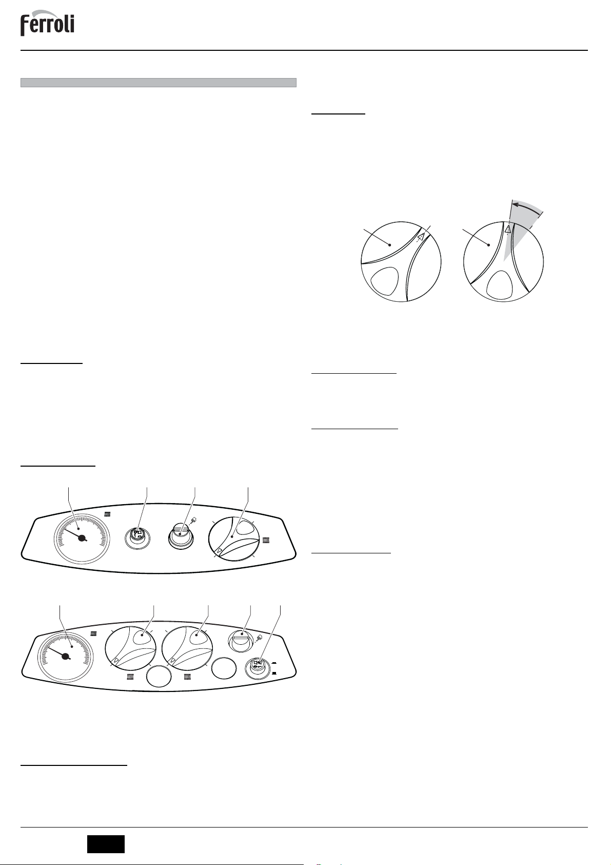
Legenda
1 = Termometro
2 = Interruttore di accensione
3 = Termostato di sicurezza a riarmo manuale
4 = Manopola regolazione temperatura o 1° stadio
5 = Manopola regolazione temperatura 2° stadio
2.3 Accensione e spegnimento
Accensione caldaia
Aprire le valvole di intercettazione combustibile.
Fornire alimentazione elettrica all'apparecchio.
Premere il pulsante 2 di fig. 1 per alimentare caldaia e bruciatore. Fare riferimento al ma-
nuale del bruciatore per il relativo funzionamento.
0
fig. 2 - Pannello di controllo modelli ATLAS 95
2
4
60 30 60
90
34
30 60
0
5
0
90
90
2
3
on
off
Spegnimento caldaia
Per brevi periodi di sosta è sufficiente premere il pulsante 2 di fig. 1 sul pannello comandi
portandolo in posizione “0”. Per lunghi periodi di sosta, oltre ad agire sul pulsante 2, è
d'obbligo chiudere anche la valvola di intercettazione del combustibile. Per lunghe soste
durante il periodo invernale, onde evitare danni causati dal gelo, è necessario introdurre
l'apposito antigelo nell'impianto o svuotare completamente l'impianto stesso.
2.4 Regolazioni
Regolazione temperatura riscaldamento
Impostare la temperatura impianto desiderata tramite il termostato di regolazione 4 di
fig. 1.
Per il modello ATLAS 95, impostare poi la temperatura del 2° stadio tramite il termostato
di regolazione 5 ad una temperatura 10°C inferiore a quella del 1° stadio.
IMPORTANTE: la temperatura del 2° stadio deve essere sempre imposta-
A
ta al di sotto di quella del 1° stadio..
-10°C
4 5
fig. 3 - Regolazione temperatura modello ATLAS 95
Regolazione della temperatura ambiente (con termostato ambiente opzionale)
Impostare tramite il termostato ambiente la temperatura desiderata all’interno dei locali.
Nel caso non sia presente il termostato ambiente la caldaia provvede a mantenere l’impianto alla temperatura di setpoint mandata impianto impostata.
3. INSTALLAZIONE
3.1 Disposizioni generali
L'INSTALLAZIONE DELLA CALDAIA DEVE ESSERE EFFETTUATA SOLTANTO DA
PERSONALE SPECIALIZZATO E DI SICURA QUALIFICAZIONE, OTTEMPERANDO A
TUTTE LE ISTRUZIONI RIPORTATE NEL PRESENTE MANUALE TECNICO, ALLE DISPOSIZIONI DI LEGGE VIGENTI, ALLE PRESCRIZIONI DELLE NORME NAZIONALI
E LOCALI E SECONDO LE REGOLE DELLA BUONA TECNICA.
3.2 Luogo d’installazione
La caldaia deve essere installata in apposito locale con aperture di aerazione verso
l’esterno secondo quanto prescritto dalle norme vigenti. Se nello stesso locale vi sono
più bruciatori o aspiratori che possono funzionare assieme, le aperture di aerazione devono essere dimensionate per il funzionamento contemporaneo di tutti gli apparecchi.Il
luogo di installazione deve essere privo di oggetti o materiali infiammabili, gas corrosivi
polveri o sostanze volatili che, richiamate dal ventilatore del bruciatore possano ostruire
i condotti interni del bruciatore o la testa di combustione. L’ambiente deve essere asciutto e non esposto a pioggia, neve o gelo.
Se l’apparecchio viene racchiuso entro mobili o montato affiancato lateralmen-
A
te, deve essere previsto lo spazio per lo smontaggio della mantellatura e per le
normali attività di manutenzione. Accertarsi in particolare che dopo il montaggio
della caldaia con il bruciatore sulla porta anteriore, quest'ultima possa aprirsi
senza che il bruciatore vada a sbattere contro pareti o altri ostacoli.
3.3 Collegamenti idraulici
La potenzialità termica dell’apparecchio va stabilita preliminarmente con un calcolo del fabbisogno
di calore dell’edificio secondo le norme vigenti. L’impianto deve essere corredato di tutti i componenti per un corretto e regolare funzionamento. Si consiglia d’interporre, fra caldaia ed impianto di
riscaldamento, delle valvole d’intercettazione che permettano, se necessario, d’isolare la caldaia
dall’impianto.
Lo scarico della valvola di sicurezza deve essere collegato ad un imbuto o tubo di raccolta, per evitare lo sgorgo di acqua a terra in caso di sovrapressione nel circuito di ri-
B
scaldamento. In caso contrario, se la valvola di scarico dovesse intervenire allagando il
locale, il costruttore della caldaia non potrà essere ritenuto responsabile.
Non utilizzare i tubi degli impianti idraulici come messa a terra di apparecchi elettrici.
Prima dell’installazione effettuare un lavaggio accurato di tutte le tubazioni dell’impianto per rimuovere residui o impurità che potrebbero compromettere il buon funzionamento dell’apparecchio.
Effettuare gli allacciamenti ai corrispettivi attacchi secondo il disegno riportato al
boli riportati sull’apparecchio.
L’apparecchio non viene fornito di vaso d’espansione. Il suo collegamento pertanto,
A
deve essere effettuato a cura dell’Installatore. Si ricorda a tal proposito, che la pressione nell’impianto, a freddo, deve essere di 1 bar.
Caratteristiche dell’acqua impianto
In presenza di acqua con durezza superiore ai 25° Fr (1°F = 10ppm CaCO3), si prescrive
l’uso di acqua opportunamente trattata, al fine di evitare possibili incrostazioni in caldaia.
Il trattamento non deve ridurre la durezza a valori inferiori a 15°F (DPR 236/88 per utilizzi
d’acqua destinati al consumo umano). È comunque indispensabile il trattamento dell’acqua utilizzata nel caso di impianti molto estesi o di frequenti immissioni di acqua di reintegro nell’impianto.
Nel caso in cui si installino decalcificatori in corrispondenza dell’entrata dell’acqua fredda alla caldaia, prestare particolare attenzione a non ridurre eccessi-
B
vamente il grado di durezza dell’acqua in quanto potrebbe verificarsi un
degrado prematuro dell’anodo di magnesio del bollitore.
60 60
cap. 5
ed ai sim-
2
IT
cod. 3540S123 - 07/2010 (Rev. 00)
ATLAS
Sistema antigelo, liquidi antigelo, additivi ed inibitori
Qualora si renda necessario, è consentito l’uso di liquidi antigelo, additivi e inibitori, solo
ed esclusivamente se il produttore di suddetti liquidi o additivi fornisce una garanzia che
assicuri che i suoi prodotti sono idonei all’uso e non arrecano danni allo scambiatore di
caldaia o ad altri componenti e/o materiali di caldaia ed impianto. È proibito l’uso di liquidi
antingelo, additivi e inibitori generici, non espressamente adatti all’uso in impianti termici
e compatibili con i materiali di caldaia ed impianto.
3.4 Collegamento bruciatore
Il bruciatore a gasolio o a gas, ad aria soffiata per focolari pressurizzati, può essere utilizzato se le sue caratteristiche di funzionamento sono adatte alle dimensioni del focolare
della caldaia ed alla sua sovrappressione. La scelta del bruciatore deve essere fatta preliminarmente seguendo le istruzioni del fabbricante, in funzione del campo di lavoro, dei
consumi del combustibile e delle pressioni, nonchè della lunghezza della camera di combustione. Montare il bruciatore seguendo le istruzioni del Suo Costruttore.
3.5 Collegamenti elettrici
Collegamento alla rete elettrica
La sicurezza elettrica dell’apparecchio è raggiunta soltanto quando lo stesso è
correttamente collegato ad un efficace impianto di messa a terra eseguito come
B
previsto dalle vigenti norme di sicurezza. Far verificare da personale professionalmente qualificato l’efficienza e l’adeguatezza dell’impianto di terra, il costruttore non è responsabile per eventuali danni causati dalla mancanza di messa
a terra dell’impianto. Far verificare inoltre che l’impianto elettrico sia adeguato
alla potenza massima assorbita dall’apparecchio, indicata in targhetta dati caldaia.
La caldaia è precablata e dotata di cavo di allacciamento alla linea elettrica di tipo "Y"
sprovvisto di spina. I collegamenti alla rete devono essere eseguiti con allacciamento fisso e dotati di un interruttore bipolare i cui contatti abbiano una apertura di almeno 3 mm,
interponendo fusibili da 3A max tra caldaia e linea. E’ importante rispettare le polarità (LINEA: cavo marrone / NEUTRO: cavo blu / TERRA: cavo giallo-verde) negli allacciamenti
alla linea elettrica. In fase di installazione o sostituzione del cavo di alimentazione, il conduttore di terra deve essere lasciato 2 cm più lungo degli altri.
II cavo di alimentazione dell’apparecchio non deve essere sostituito dall’utente.
In caso di danneggiamento del cavo, spegnere l’apparecchio e, per la sua so-
B
stituzione, rivolgersi esclusivamente a personale professionalmente qualificato. In caso di sostituzione del cavo elettrico di alimentazione, utilizzare
esclusivamente cavo “HAR H05 VV-F” 3x0,75 mm2 con diametro esterno
massimo di 8 mm.
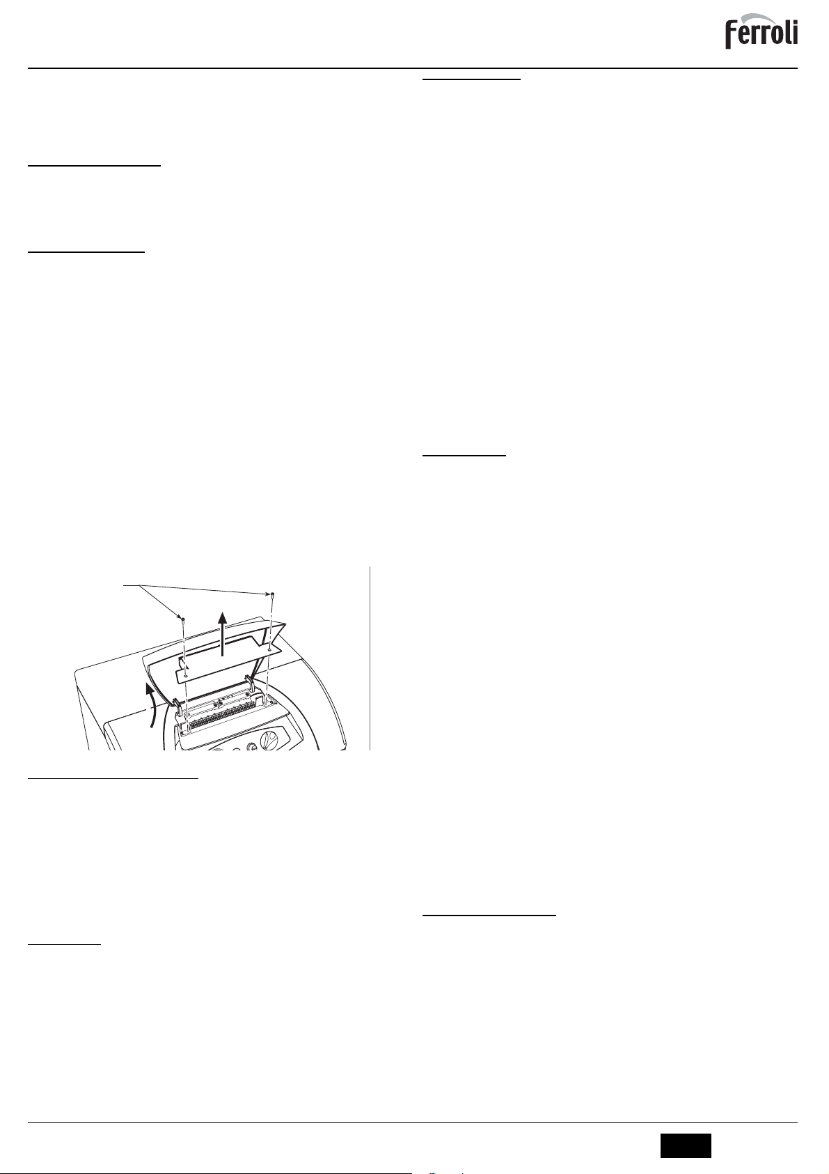
Accesso alla morsettiera elettrica
Svitare le due viti “A” poste sulla parte superiore del cruscotto e rimuovere lo sportellino
“B“.
A
2
B
1
fig. 4 - Accesso alla morsettiera
3.6 Collegamento alla canna fumaria
L’apparrecchio deve essere collegato ad una canna fumaria progettata e costruita nel
rispetto delle norme vigenti. Il condotto tra caldaia e canna fumaria deve essere di materiale adatto allo scopo, resistente cioè alla temperatura ed alla corrosione. Nei punti di
giunzione si raccomanda di curare la tenuta e di isolare termicamente tutto il condotto
tra caldaia e camino, per evitare la formazione di condensa.
4. SERVIZIO E MANUTENZIONE
Tutte le operazioni di regolazione, trasformazione, messa in servizio, manutenzione descritte di seguito, devono essere effettuate solo da Personale Qualificato e di sicura qualificazione (in possesso dei requisiti tecnici professionali previsti dalla normativa vigente)
come il personale del Servizio Tecnico Assistenza Clienti di Zona.
FERROLI declina ogni responsabilità per danni a cose e/o persone derivanti dalla manomissione dell’apparecchio da parte di persone non qualificate e non autorizzate.
4.1 Regolazioni
Regolazione bruciatore
Il rendimento della caldaia ed il corretto funzionamento dipendono soprattutto dall'accuratezza delle regolazioni del bruciatore. Seguire attentamente le istruzioni del relativo
produttore. I bruciatori a due stadi devono avere il primo stadio regolato ad una potenza
non inferiore alla potenza minima nominale della caldaia. La potenza del secondo stadio
non deve essere superiore a quella nominale massima della caldaia.
4.2 Messa in servizio
Verifiche da eseguire alla prima accensione, e dopo tutte le operazioni di manutenzione che abbiano comportato la disconnessione dagli impianti o un inter-
B
vento su organi di sicurezza o parti della caldaia:
Prima di accendere la caldaia
• Aprire le eventuali valvole di intercettazione tra caldaia ed impianti.
• Verificare la tenuta dell’impianto combustibile.
• Verificare la corretta precarica del vaso di espansione
• Riempire l’impianto idraulico ed assicurare un completo sfiato dell’aria contenuta
nella caldaia e nell’impianto, aprendo la valvola di sfiato aria posta nella caldaia e le
eventuali valvole di sfiato sull’impianto.
• Verificare che non vi siano perdite di acqua nell’impianto, nei circuiti acqua sanitaria,
nei collegamenti o in caldaia.
• Verificare l’esatto collegamento dell’impianto elettrico e la funzionalità dell’impianto
di terra
• Verificare che non vi siano liquidi o materiali infiammabili nelle immediate vicinanze
della caldaia
Verifiche durante il funzionamento
• Accendere l’apparecchio come descritto nella sez. 2.3.
• Assicurarsi della tenuta del circuito del combustibile e degli impianti acqua.
• Controllare l’efficienza del camino e condotti aria-fumi durante il funzionamento della caldaia.
• Controllare che la circolazione dell’acqua, tra caldaia ed impianti, avvenga correttamente.
• Verificare la buona accensione della caldaia, effettuando diverse prove di accensione e spegnimento, per mezzo del termostato ambiente o del comando remoto.
• Assicurarsi che il consumo del combustibile indicato al contatore, corrisponda a
quello indicato nella tabella dati tecnici alla sez. 5.3.
• Verificare che la porta bruciatore e camera fumo siano a tenuta.
• Verificare che il bruciatore funzioni correttamente. Questo controllo va fatto con gli
appositi strumenti seguendo le istruzioni del costruttore.
4.3 Manutenzione
Controllo periodico
Per mantenere nel tempo il corretto funzionamento dell’apparecchio, è necessario far
eseguire da personale qualificato un controllo annuale che preveda le seguenti verifiche:
• I dispositivi di comando e di sicurezza devono funzionare correttamente.
• Il circuito di evacuazione fumi deve essere in perfetta efficienza.
• Controllare che non ci siano eventuali occlusioni o ammaccature nei tubi di alimentazione e ritorno del combustibile.
• Effettuare la pulizia del filtro di linea di aspirazione del combustibile.
• Rilevare il corretto consumo di combustibile
• Effettuare la pulizia della testa di combustione nella zona di uscita del combustibile,
sul disco di turbolenza.
• Lasciare funzionare il bruciatore a pieno regime per circa dieci minuti, quindi effettuare un'analisi della combustione verificando:
- Le corrette tarature di tutti gli elementi indicati nel presente manuale
- Temperature dei fumi al camino
- Contenuto della percentuale di CO
• I condotti ed il terminale aria-fumi devono essere liberi da ostacoli e non presentare
perdite
• Il bruciatore e lo scambiatore devono essere puliti ed esenti da incrostazioni. Per
l’eventuale pulizia non usare prodotti chimici o spazzole di acciaio.
• Gli impianti combustibile e acqua devono essere a tenuta.
• La pressione dell’acqua dell’impianto a freddo deve essere di circa 1 bar; in caso
contrario riportarla a questo valore.
• La pompa di circolazione non deve essere bloccata.
• Il vaso d’espansione (non fornito) deve essere carico.
L’eventuale pulizia del mantello, del cruscotto e delle parti estetiche della cal-
A
daia può essere eseguita con un panno morbido e umido eventualmente imbevuto con acqua saponata. Tutti i detersivi abrasivi e i solventi sono da evitare.
Pulizia della caldaia
1. Togliere l’alimentazione elettrica alla caldaia.
2. Togliere il pannello anteriore superiore e quello inferiore.
3. Aprire la porta svitando i relativi pomelli.
4. Pulire l’interno della caldaia e tutto il percorso dei fumi di scarico, tramite uno scovolo o con aria compressa.
5. Richiudere infine la porta, fissandola con il relativo pomello.
Per la pulizia del bruciatore, consultare le istruzioni della Ditta Costruttrice.
4.4 Risoluzione dei problemi
Anomalie
Possono verificarsi due condizioni di blocco ripristinabili dall’utente:
A Blocco del bruciatore segnalato dall’apposita spia. Riferirsi al manuale del bru-
ciatore.
B Intervento del termostato di sicurezza che avviene quando la temperatura in
caldaia raggiunge un valore oltre al quale può crearsi una condizione di pericolo. Per ripristinare il funzionamento, svitare il tappo 3 di fig. 1 e premere il pulsante di riarmo sottostante.
Se il problema si ripete, richiedere l’intervento di Personale Qualificato o del centro assistenza.
In caso di guasto e/o cattivo funzionamento dell’apparecchio, disattivarlo, astenendosi
da qualsiasi tentativo di riparazione o di intervento diretto. Rivolgersi esclusivamente a
personale professionalmente qualificato ed autorizzato.
2
6
cod. 3540S123 - 07/2010 (Rev. 00)
IT
3
ATLAS
5. CARATTERISTICHE E DATI TECNICI
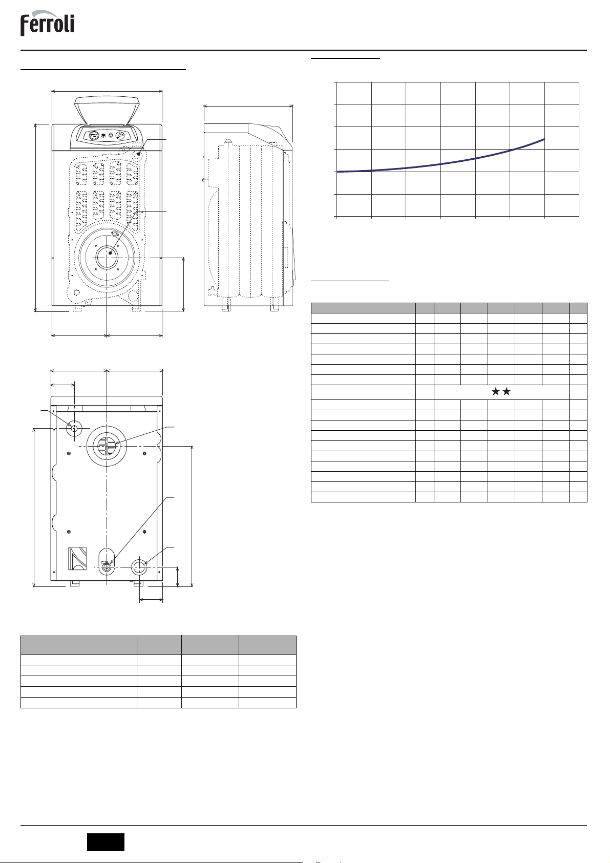
5.1 Dimensioni, attacchi e componenti principali
500
34
a5
850
250 250
250 250
105
a1
a4
a3
705
245
626
5.2 Perdita di carico
Perdita di carico lato acqua
60
C
50
40
A
30
20
10
0
2000 2500 3000 3500 4000 4500 5000 5500
B
fig. 6 - Perdite di carico
A mbar
B Portata l/h
5.3 Tabella dati tecnici
Modello ATLAS 32 ATLAS 47 ATLAS 62 ATLAS 78 ATLAS 95
Numero elementi n°34567
Portata termica max kW 34.9 51.6 67.7 85.6 103.2 (Q)
Portata termica min kW 17.0 34.3 45.8 59.0 70.8 (Q)
Potenza termica max riscaldamento kW 32 47 62 78 95 (P)
Potenza termica min riscaldamento kW 16 32 43 55 66 (P)
Rendimento Pmax (80-60°C) % 91.7 91.1 91.5 91.1 92
Rendimento 30% % 94.3 93.5 94.0 93.5 93.8
Classe efficienza direttiva 92/42 EEC
Pressione max esercizio riscaldamento bar66666(PMS)
Pressione min esercizio riscaldamento bar 0.8 0.8 0.8 0.8 0.8
Temperatura max riscaldamento °C 95 95 95 95 95 (tmax)
Contenuto acqua riscaldamento l 18 23 28 33 38
Grado protezione IP X0D X0D X0D X0D X0D
Tensione di alimentazione V/Hz 230/50 230/50 230/50 230/50 230/50
Peso a vuoto kg 127 166 205 244 283
Lunghezza camera di combustione mm 350 450 550 650 750
Diametro camera di combustione mm 300 300 300 300 300
Perdita di carico lato fumi mbar 0.2 0.27 0.4 0.4 0.63
a2
85
105
fig. 5 - Dimensionale, attacchi e componenti principali
Modello
ATL AS 3 2
ATL AS 4 7
ATL AS 6 2
ATL AS 7 8
ATL AS 9 5
a1 Mandata impianto - 1” 1/2”
a2 Ritorno impianto - 1” 1/2”
a3 Scarico impianto di riscaldamento - 1/2”
a4 Attacco camino
a5 Attacco bruciatore
34 Bulbo temperatura riscaldamento e sicurezza
4
IT
C
mm
400 120÷130 115
500 120÷130 115
600 120÷130 115
700 120÷130 115
800 120÷130 115
a4
Ø mm
a5
Ø mm
cod. 3540S123 - 07/2010 (Rev. 00)
ATLAS
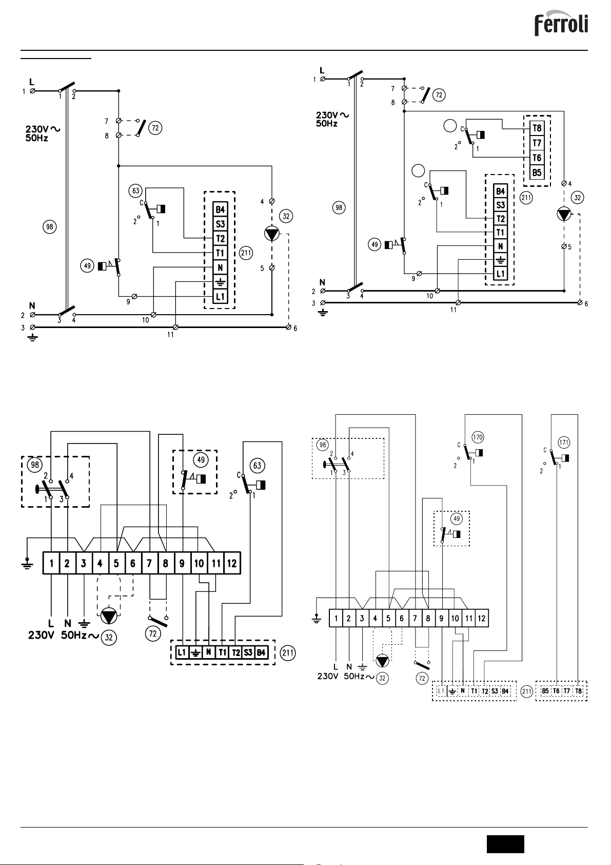
5.4 Schema elettrico
Schema elettrico di principio ATLAS 32-78
1
c
fig. 7 - Schema elettrico di principio ATLAS 32-78
Legenda fig. 7 e fig. 8
32 Circolatore riscaldamento (non fornito)
49 Termostato di sicurezza
72 Termostato ambiente (non fornito)
63 Termostato di regolazione caldaia
98 Interruttore
211 Connettore bruciatore (non fornito)
Schema elettrico di allacciamento ATLAS 32-78
Schema elettrico di principio ATLAS 95
171
170
1
c
fig. 9 - Schema elettrico di principio ATLAS 95
Legenda fig. 9 e fig. 10
32 Circolatore riscaldamento (non fornito)
49 Termostato di sicurezza
72 Termostato ambiente (non fornito)
98 Interruttore
170 Termostato di regolazione caldaia 1° Stadio
171 Termostato di regolazione caldaia 2° Stadio
211 Connettore bruciatore (non fornito)
Schema elettrico di allacciamento ATLAS 95
1
c
fig. 8 - Schema elettrico di allacciamento ATLAS 32-78
1
c
fig. 10 - Schema elettrico di allacciamento ATLAS 95
6
cod. 3540S123 - 07/2010 (Rev. 00)
IT
5

ATLAS
EN
1. GENERAL INSTRUCTIONS
• Carefully read the instructions contained in this instruction booklet.
• After boiler installation, inform the user regarding its operation and give him this
manual, which is an integral and essential part of the product and must be kept with
care for future reference.
• Installation and maintenance must be carried out by professionally qualified personnel, according to current regulations and the manufacturer's instructions. Do not carry out any operation on the sealed control parts.
• Incorrect installation or inadequate maintenance can result in damage or injury. The
Manufacturer declines any liability for damage due to errors in installation and use
or failure to follow the instructions.
• Before carrying out any cleaning or maintenance operation, disconnect the unit from
the power supply using the system switch and/or the special cut-off devices.
• In case of a fault and/or poor operation, deactivate the unit and do not attempt to
repair it or directly intervene. Contact professionally qualified personnel. Repair/replacement of the products must only be carried out by professionally qualified using
original spare parts. Failure to comply with the above could affect the safety of the
unit.
• This unit must only be used for its intended purpose. Any other use is considered
improper and therefore dangerous.
• The packing materials are potentially hazardous and must not be left within the
reach of children.
• The images given in this manual are a simplified representation of the product. In
this representation there may be slight and insignificant differences with respect to
the product supplied.
2. OPERATING INSTRUCTIONS
2.1 Introduction
Dear Customer,
Thank you for choosing a FERROLI boiler featuring advanced design, cutting-edge
technology, high reliability and quality construction. Please read this manual carefully
since it provides important information on safe installation, use and maintenance.
ATLAS is a high-efficiency heat generator for the production of heating hot water, suitable for operation with blown oil or gas burners. The boiler shell consists of cast iron elements, assembled with steel stays and double cones, whose profile is specially designed
with optimum division of the fins, offering high thermal efficiency and therefore high energy-saving.
2.2 Control panel
1
°C
60
40
80
20
100
0 120
°C
fig. 1 - Control panel for models ATLAS 32-78
1
30
°C
60
40
80
20
100
0 120
°C
Key
1 = Thermometer
2 = Ignition switch
3 = Manual reset safety thermostat
4 = 1st stage temperature control knob
5 = 2nd stage temperature control knob
2.3 Turning on and off
Boiler lighting
Open the fuel shutoff valves.
Switch on the power to the unit.
Press button 2 of fig. 1 to feed the boiler and burner. Refer to the burner manual for op-
eration.
Turning the boiler off
For brief shutdown periods just press button 2 of fig. 1 on the control panel , bringing it
to position “0”. For long shutdown periods, as well as operating button 2 also close the
fuel shutoff valve . To avoid damage caused by freezing during long shutdowns in winter,
add a suitable antifreeze to the system or completely drain the system.
0
fig. 2 - Control panel for models ATLAS 95
2
4
60 30 60
90
34
30 60
0
5
0
90
90
2
3
on
off
2.4 Adjustments
Heating temperature setting
Set the required system temperature with the control thermostat 4 of fig. 1.
For the model ATLAS 95, with the control thermostat 5 then set the temperature of the
2nd stage to a temperature 10°C lower than that of the 1st stage.
IMPORTANT: The temperature setting of the 2nd stage must always be
A
lower than that of the 1st stage..
-10°C
4 5
fig. 3 - Temperature adjustment for model ATLAS 95
Room temperature adjustment (with optional room thermostat)
Using the room thermostat, set the temperature desired in the rooms. If the room thermostat is not installed the boiler will keep the heating system at its setpoint temperature.
3. INSTALLATION
3.1 General Instructions
BOILER INSTALLATION MUST ONLY BE PERFORMED BY QUALIFIED PERSONNEL, IN ACCORDANCE WITH ALL THE INSTRUCTIONS GIVEN IN THIS TECHNICAL
MANUAL, THE PROVISIONS OF CURRENT LAW, THE PRESCRIPTIONS OF NATIONAL AND LOCAL STANDARDS AND THE RULES OF PROPER WORKMANSHIP.
3.2 Place of installation
The boiler must be installed in a special room with ventilation openings towards the outside in conformity with current regulations. If there are several burners or extraction units
that can work together in the same room, the ventilation openings must be sized for simultaneous operation of all the units. The place of installation must be free of flammable
objects or materials, corrosive gases, volatile substances or dusts which, sucked by the
burner fan, can obstruct the pipes inside the burner or the combustion head. The room
must be dry and not exposed to rain, snow or frost.
If the unit is enclosed in a cabinet or mounted alongside, a space must be pro-
A
vided for removing the casing and for normal maintenance operations. In particular, after boiler installation with burner on the front door, make sure the front
door can open freely without the burner striking walls or other obstacles.
3.3 Plumbing connections
The heating capacity of the unit must be previously established by calculating the building's heat requirement according to the current regulations. The system must be provided with all the components for correct and regular operation. It is advisable to install
shutoff valves between the boiler and heating system allowing the boiler to be isolated
from the system if necessary.
The safety valve outlet must be connected to a funnel or collection pipe to prevent water spurting onto the floor in case of overpressure in the heating circuit.
B
Otherwise, if the discharge valve cuts in and floods the room, the boiler manufacturer cannot be held liable.
Do not use the water system pipes to earth electrical appliances.
Before installation, carefully wash all the pipes of the system to remove any residuals or
impurities that could affect proper operation of the unit.
Carry out the relevant connections according to the diagram in and thecap. 5 symbols
given on the unit.
The unit is not supplied with an expansion tank; its connection must therefore
A
be carried out by the Installer. The pressure in the system, when cold, must be
1 bar.
Water system characteristics
In the presence of water harder than 25° Fr (1°F = 10ppm CaCO3), use suitably treated
water in order to avoid possible scaling in the boiler. Treatment must not reduce the hardness to values below 15°F (Decree 236/88 for uses of water intended for human consumption). Treatment of the water used is indispensable in case of very large systems
or with frequent introduction of replenishing water in the system.
If water softeners are installed at the boiler cold water inlet, make sure not to
reduce the water hardness too much, as this could cause early deterioration of
B
the magnesium anode in the hot water tank.
Antifreeze system, antifreeze fluids, additives and inhibitors
If it becomes necessary, it is permissible to use antifreeze fluid, additives and inhibitors
only if the manufacturer of these fluids or additives guarantees they are suitable for this
use and cause no damage to the heat exchanger or other components and/or materials
of the boiler unit and system. It is prohibited to use generic antifreeze fluid, additives or
inhibitors that are not expressly suited for use in heating systems and compatible with
the materials of the boiler unit and system.
3.4 Burner connection
An oil or gas burner, with blown air for pressured furnaces, can be used if its operation
characteristics are suitable for the size of the boiler furnace and its overpressure. The
choice of burner must be made beforehand, following the manufacturer's instructions,
according to the work range, fuel consumption and pressures, as well as the length of
the firebox. Install the burner in compliance with the Manufacturer's instructions.
60 60
cod. 3540S123 - 07/2010 (Rev. 00)
EN
17

ATLAS
3.5 Electrical connections
Connection to the electrical grid
The unit's electrical safety is only guaranteed when correctly connected to an
efficient earthing system executed according to current safety standards. Have
B
the efficiency and suitability of the earthing system checked by professionally
qualified personnel. The manufacturer is not responsible for any damage
caused by failure to earth the system. Also make sure that the electrical system
is adequate for the maximum power absorbed by the unit, as specified on the
boiler dataplate.
The boiler is prewired and provided with a Y-cable and plug for connection to the electricity line. The connections to the grid must be made with a permanent connection and
equipped with a bipolar switch whose contacts have a minimum opening of at least 3
mm, interposing fuses of max. 3A between the boiler and the line. It is important to respect the polarities (LINE: brown wire / NEUTRAL: blue wire / EARTH: yellow-green
wire) in making connections to the electrical line. During installation or when changing
the power cable, the earth wire must be left 2 cm longer than the others.
The user must never change the unit's power cable. If the cable gets damaged,
switch off the unit and have it changed solely by professionally qualified person-
B
nel. If changing the electric power cable, use solely “HAR H05 VV-F” 3x0.75
mm2 cable with a maximum outside diameter of 8 mm.
Accessing the electrical terminal block
Undo the two screws “A” located on the top part of the control panel and remove the
cover “B“.
A
2
B
1
fig. 4 - Accessing the terminal block
3.6 Connection to the flue
The unit must be connected to a flue designed and built in compliance with current regulations. The pipe between the boiler and flue must be made from material suitable for
the purpose, i.e. heat and corrosion resistant. Ensure the seal at the joints and insulate
the entire pipe between boiler and flue, to prevent the formation of condensate.
4. SERVICE AND MAINTENANCE
All adjustment, conversion, start-up and maintenance operations described below must only be
carried out by Qualified Personnel (meeting the professional technical requirements prescribed by
current regulations) such as those of the Local After-Sales Technical Service.
FERROLI
declines any liability for damage and/or injury caused by unqualified and unauthorised
people tampering with the unit.
4.1 Adjustments
Burner adjustment
Boiler efficiency and correct operation depend above all on accurate burner adjustments. Carefully
follow the Manufacturer's instructions. The two-stage burners must have the first stage adjusted to
a power level not below the boiler's rated min. power. The power of the second stage must not be
higher than the boiler's rated max. power.
4.2 Start-up
Checks to be made at first lighting and after all maintenance operations that involved disconnecting from the systems or an operation on safety devices or parts of the boiler:
B
Before lighting the boiler
• Open any on-off valves between the boiler and the systems.
• Check the seal of the fuel system.
• Check correct prefilling of the expansion tank.
• Fill the water system and make sure that all air contained in the boiler and the system has
been vented, by opening the air valve on the boiler and any air valves on the system.
• Make sure there are no water leaks in the system, domestic hot water circuits, connections
or boiler.
• Check correct connection of the electrical system and efficiency of the earthing system
• Make sure there are no flammable liquids or materials in the immediate vicinity of the boiler
Checks during operation
• Light the unit on as described in sec. 2.3.
• Make sure the fuel circuit and water systems are tight.
• Check the efficiency of the flue and air/fume ducts while the boiler is working.
• Make sure the water is circulating properly between the boiler and the systems.
• Check proper lighting of the boiler by doing several tests, turning it on and off with
the room thermostat or remote control.
• Make sure the fuel consumption indicated on the meter matches that given in the
technical data table on sec. 5.3.
• Make sure the fumebox and burner door are tight.
• Make sure the burner works properly. This check must be made with the special instruments, following the manufacturer's instructions.
4.3 Maintenance
Periodical check
To ensure correct operation of the unit over time, have qualified personnel carry out a
yearly check, providing for the following:
• The control and safety devices must function correctly.
• The fume evacuation circuit must be perfectly efficient.
• Make sure there are no obstructions or dents in the fuel supply and return pipes.
• Clean the filter of the fuel suction line.
• Measure the correct fuel consumption
• Clean the combustion head in the fuel outlet zone, on the swirl disc.
• Leave the burner on at max. for about ten minutes, then analyse the combustion,
checking:
- Correct setting of the elements specified in this manual.
- Temperatures of fumes at the flue
-CO
percentage content
2
• The air/fume terminal and ducts must be free of obstructions and leaks
• The burner and exchanger must be clean and free of deposits. For cleaning do not
use chemical products or wire brushes.
• The fuel and water systems must be tight.
• The water pressure in the system when cold must be approx. 1 bar; otherwise bring
it to that value.
• The circulating pump must not be blocked.
• The expansion tank (not supplied) must be filled.
The boiler casing, control panel and aesthetic parts can be cleaned with a soft
A
damp cloth, if necessary soaked in soapy water. Do not use any abrasive detergents and solvents.
Boiler cleaning
1. Disconnect the power supply to the boiler.
2. Remove the front top and bottom panel.
3. Open the door by undoing the knobs.
4. Clean the inside of the boiler and the entire path of exhaust fumes, using a tube
brush or compressed air.
5. Then close the door, securing it with the knob.
To clean the burner, refer to the Manufacturer's instructions.
4.4 Troubleshooting
Fault
Two shutdown conditions resettable by the user can occur :
A Burner shutdown signalled by the special indicator. Refer to the burner manual.
B Cutting in of the safety thermostat, which occurs when the boiler temperature
reaches a value beyond which a dangerous condition may be created. To restore operation, unscrew cap 3 of fig. 1 and press the reset button below.
If the problem persists, request the assistance of Qualified Personnel or the After-Sales
Centre.
In case of a fault and/or poor operation, deactivate the unit, do not try to fix the problem
or directly carry out any operation. Contact authorised and professionally qualified personnel.
18
EN
cod. 3540S123 - 07/2010 (Rev. 00)

ATLAS
5. TECHNICAL DATA AND CHARACTERISTICS
5.1 Dimensions, connections and main components
500
34
a5
850
245
250 250
250 250
105
a1
a4
a3
705
626
5.2 Pressure loss
Pressure loss water side
60
C
50
40
A
30
20
10
0
2000 2500 3000 3500 4000 4500 5000 5500
B
fig. 6 - Pressure loss
A mbar
B Flowrate l/h
5.3 Technical data table
Model ATLAS 32 ATL AS 47 ATL AS 62 ATLAS 78 ATLAS 95
Number of elements n° 3 4 5 6 7
Max. heating capacity kW 34.9 51.6 67.7 85.6 103.2 (Q)
Min. heating capacity kW 17.0 34.3 45.8 59.0 70.8 (Q)
Max. heat output in heating kW 32 47 62 78 95 (P)
Min. heat output in heating kW 16 32 43 55 66 (P)
Efficiency Pmax (80-60°C) % 91.7 91.1 91.5 91.1 92
Efficiency 30% % 94.3 93.5 94.0 93.5 93.8
Efficiency class Directive 92/42 EEC
Max. working pressure in heating bar 6 6 6 6 6 (PMS)
Min. working pressure in heating bar 0.8 0.8 0.8 0.8 0.8
Max. heating temperature °C 95 95 95 95 95 (tmax)
Heating water content l 18 23 28 33 38
Protection rating IP X0D X0D X0D X0D X0D
Power supply voltage V/Hz 230/50 230/50 230/50 230/50 230/50
Empty weight kg 127 166 205 244 283
Combustion chamber length mm 350 450 550 650 750
Combustion chamber diameter mm 300 300 300 300 300
Pressure loss fume side mbar 0.2 0.27 0.4 0.4 0.63
105
fig. 5 - Dimensions, connections and main components
Model
ATL AS 3 2
ATL AS 4 7
ATL AS 6 2
ATL AS 7 8
ATL AS 9 5
a1 System delivery - 1” 1/2”
a2 System return - 1” 1/2”
a3 Heating system drain - 1/2”
a4 Flue connection
a5 Burner connection
34 Safety and heating temperature bulb
mm
400 120÷130 115
500 120÷130 115
600 120÷130 115
700 120÷130 115
800 120÷130 115
a2
85
C
a4
Ø mm
a5
Ø mm
cod. 3540S123 - 07/2010 (Rev. 00)
EN
19

ATLAS
5.4 Wiring diagram
Main wiring diagram ATLAS 32-78
1
c
fig. 7 - Main wiring diagram ATLAS 32-78
Key fig. 7 and fig. 8
32 Heating circulating pump (not supplied)
49 Safety thermostat
72 Room thermostat (not supplied)
63 Boiler control thermostat
98 Switch
211 Burner connector (not supplied)
Electrical connection diagram ATLAS 32-78
Main wiring diagram ATLAS 95
171
170
1
c
fig. 9 - Main wiring diagram ATLAS 95
Key fig. 9 and fig. 10
32 Heating circulating pump (not supplied)
49 Safety thermostat
72 Room thermostat (not supplied)
98 Switch
170 1st Stage boiler control thermostat
171 2nd Stage boiler control thermostat
211 Burner connector (not supplied)
Electrical connection diagram ATLAS 95
1
c
fig. 8 - Electrical connection diagram ATLAS 32-78
1
c
fig. 10 - Electrical connection diagram ATLAS 95
20
EN
cod. 3540S123 - 07/2010 (Rev. 00)

ATLAS
RU
1. ɈȻɓɂȿɍɄȺɁȺɇɂʇɉɈɌȿɏɇɂɄȿȻȿɁɈɉȺɋɇɈɋɌɂ
• ȼɧɢɦɚɬɟɥɶɧɨɩɪɨɱɢɬɚɣɬɟɩɪɟɞɭɩɪɟɠɞɟɧɢɹ, ɫɨɞɟɪɠɚɳɢɟɫɹɜɧɚɫɬɨɹɳɟɦɪɭɤɨɜɨɞɫɬɜɟ.
• ɉɨɫɥɟɭɫɬɚɧɨɜɤɢɤɨɬɥɚɩɪɨɢɧɮɨɪɦɢɪɭɣɬɟɩɨɥɶɡɨɜɚɬɟɥɹɨɩɪɢɧɰɢɩɚɯɪɚɛɨɬɵɚɝɪɟɝɚɬɚɢɩɟɪɟɞɚɣɬɟ
ɟɦɭɧɚɫɬɨɹɳɟɟɪɭɤɨɜɨɞɫɬɜɨ; ɨɧɨɹɜɥɹɟɬɫɹɫɭɳɟɫɬɜɟɧɧɨɣɢɧɟɨɬɴɟɦɥɟɦɨɣɱɚɫɬɶɸɢɡɞɟɥɢɹɢɞɨɥɠɧɨ
ɛɟɪɟɠɧɨɫɨɯɪɚɧɹɬɶɫɹɞɥɹɢɫɩɨɥɶɡɨɜɚɧɢɹɜɛɭɞɭɳɟɦ.
• ɍɫɬɚɧɨɜɤɚɢɬɟɯɧɢɱɟɫɤɨɟɨɛɫɥɭɠɢɜɚɧɢɟɤɨɬɥɚɞɨɥɠɧɵɩɪɨɢɡɜɨɞɢɬɶɫɹɤɜɚɥɢɮɢɰɢɪɨɜɚɧɧɵɦ
ɩɟɪɫɨɧɚɥɨɦ ɩɪɢɫɨɛɥɸɞɟɧɢɢ ɞɟɣɫɬɜɭɸɳɢɯ ɧɨɪɦ ɢ ɜɫɨɨɬɜɟɬɫɬɜɢɢ ɫ ɭɤɚɡɚɧɢɹɦɢɢɡɝɨɬɨɜɢɬɟɥɹ.
Ɂɚɩɪɟɳɚɟɬɫɹɜɵɩɨɥɧɹɬɶɤɚɤɢɟ-ɥɢɛɨɪɚɛɨɬɵɧɚɨɩɥɨɦɛɢɪɨɜɚɧɧɵɯɪɟɝɭɥɢɪɨɜɨɱɧɵɯɭɫɬɪɨɣɫɬɜɚɯ.
• ɇɟɩɪɚɜɢɥɶɧɚɹɭɫɬɚɧɨɜɤɚɢɥɢɧɟɧɚɞɥɟɠɚɳɟɟɬɟɯɧɢɱɟɫɤɨɟɨɛɫɥɭɠɢɜɚɧɢɟɦɨɝɭɬɩɪɢɜɟɫɬɢɤ
ɦɚɬɟɪɢɚɥɶɧɨɦɭɭɳɟɪɛɭɢɥɢɬɪɚɜɦɚɦɥɸɞɟɣɢɠɢɜɨɬɧɵɯ. ɂɡɝɨɬɨɜɢɬɟɥɶɧɟɧɟɫɟɬɧɢɤɚɤɨɣ
ɨɬɜɟɬɫɬɜɟɧɧɨɫɬɢɡɚɭɳɟɪɛ, ɫɜɹɡɚɧɧɵɣɫɨɲɢɛɨɱɧɵɦɢɭɫɬɚɧɨɜɤɨɣɢɷɤɫɩɥɭɚɬɚɰɢɟɣɚɩɩɚɪɚɬɚ, ɚɬɚɤɠɟ
ɫɧɟɫɨɛɥɸɞɟɧɢɟɦɩɪɟɞɨɫɬɚɜɥɟɧɧɵɯɢɦɢɧɫɬɪɭɤɰɢɣ.
• ɉɟɪɟɞɜɵɩɨɥɧɟɧɢɟɦɥɸɛɨɣɨɩɟɪɚɰɢɢɩɨɱɢɫɬɤɟɢɥɢɬɟɯɧɢɱɟɫɤɨɦɭɨɛɫɥɭɠɢɜɚɧɢɸɨɬɫɨɟɞɢɧɢɬɟɚɝɪɟɝɚɬ
ɨɬɫɟɬɢ ɷɥɟɤɬɪɨɩɢɬɚɧɢɹɫ ɩɨɦɨɳɶɸɝɥɚɜɧɨɝɨ ɪɭɛɢɥɶɧɢɤɚɢ/ɢɥɢ ɩɪɟɞɭɫɦɨɬɪɟɧɧɵɯɞɥɹ ɷɬɨɣɰɟɥɢ
ɨɬɫɟɱɧɵɯɭɫɬɪɨɣɫɬɜ.
• ȼɫɥɭɱɚɟɧɟɢɫɩɪɚɜɧɨɣɢ/ɢɥɢɧɟɧɨɪɦɚɥɶɧɨɣɪɚɛɨɬɵɚɝɪɟɝɚɬɚ, ɜɵɤɥɸɱɢɬɟɟɝɨɢɜɨɡɞɟɪɠɢɬɟɫɶɨɬɥɸɛɨɣ
ɩɨɩɵɬɤɢɫɚɦɨɫɬɨɹɬɟɥɶɧɨɨɬɪɟɦɨɧɬɢɪɨɜɚɬɶɢɥɢɭɫɬɪɚɧɢɬɶɩɪɢɱɢɧɭɧɟɢɫɩɪɚɜɧɨɫɬɢ. ȼɬɚɤɢɯɫɥɭɱɚɹɯ
ɨɛɪɚɳɚɣɬɟɫɶɢɫɤɥɸɱɢɬɟɥɶɧɨɤɤɜɚɥɢɮɢɰɢɪɨɜɚɧɧɵɦɫɩɟɰɢɚɥɢɫɬɚɦ. ȼɨɡɦɨɠɧɵɟɨɩɟɪɚɰɢɢɩɨ
ɪɟɦɨɧɬɭ-ɡɚɦɟɧɟɤɨɦɩɥɟɤɬɭɸɳɢɯɞɨɥɠɧɵɜɵɩɨɥɧɹɬɶɫɹɬɨɥɶɤɨɤɜɚɥɢɮɢɰɢɪɨɜɚɧɧɵɦɢɫɩɟɰɢɚɥɢɫɬɚɦɢ
ɫɢɫɩɨɥɶɡɨɜɚɧɢɟɦɢɫɤɥɸɱɢɬɟɥɶɧɨɨɪɢɝɢɧɚɥɶɧɵɯɡɚɩɱɚɫɬɟɣ. ɇɟɫɨɛɥɸɞɟɧɢɟɜɫɟɝɨɜɵɲɟɭɤɚɡɚɧɧɨɝɨ
ɦɨɠɟɬɧɚɪɭɲɢɬɶɛɟɡɨɩɚɫɧɨɫɬɶɪɚɛɨɬɵɚɝɪɟɝɚɬɚ.
• ɇɚɫɬɨɹɳɢɣɚɝɪɟɝɚɬɫɥɟɞɭɟɬɢɫɩɨɥɶɡɨɜɚɬɶɬɨɥɶɤɨɩɨɩɪɟɞɭɫɦɨɬɪɟɧɧɨɦɭɧɚɡɧɚɱɟɧɢɸ. Ʌɸɛɨɟɩɪɨɱɟɟ
ɢɫɩɨɥɶɡɨɜɚɧɢɟɫɥɟɞɭɟɬɫɱɢɬɚɬɶɧɟɩɪɚɜɢɥɶɧɵɦɢ, ɫɥɟɞɨɜɚɬɟɥɶɧɨ, ɩɪɟɞɫɬɚɜɥɹɸɳɢɦɨɩɚɫɧɨɫɬɶ.
• ɍɩɚɤɨɜɨɱɧɵɟɦɚɬɟɪɢɚɥɵ ɹɜɥɹɸɬɫɹ ɢɫɬɨɱɧɢɤɨɦ ɩɨɬɟɧɰɢɚɥɶɧɨɣ ɨɩɚɫɧɨɫɬɢɢ ɧɟɞɨɥɠɧɵ ɛɵɬɶ
ɨɫɬɚɜɥɟɧɵɜɦɟɫɬɚɯ, ɞɨɫɬɭɩɧɵɯɞɟɬɹɦ.
• ɉɪɢɜɟɞɟɧɧɵɟɜɧɚɫɬɨɹɳɟɦɪɭɤɨɜɨɞɫɬɜɟɢɡɨɛɪɚɠɟɧɢɹɞɚɸɬɭɩɪɨɳɟɧɧɨɟɩɪɟɞɫɬɚɜɥɟɧɢɟɨɛɚɝɪɟɝɚɬɟɢ
ɦɨɝɭɬɫɨɞɟɪɠɚɬɶɧɟɫɭɳɟɫɬɜɟɧɧɵɟɨɬɥɢɱɢɹɨɬɩɨɫɬɚɜɥɟɧɧɨɝɨɢɡɞɟɥɢɹ.
2. ɂɇɋɌɊɍɄɐɂɂɉɈɗɄɋɉɅɍȺɌȺɐɂɂ
2.1 ɉɪɟɞɢɫɥɨɜɢɟ
ɍɜɚɠɚɟɦɵɣɩɨɤɭɩɚɬɟɥɶ,
FERROLI
Ȼɥɚɝɨɞɚɪɢɦȼɚɫɡɚɬɨ, ɱɬɨȼɵɜɵɛɪɚɥɢɤɨɬɟɥ
ɤɨɧɫɬɪɭɤɰɢɸ, ɜɵɩɨɥɧɟɧɧɵɣɩɨɩɟɪɟɞɨɜɵɦɬɟɯɧɨɥɨɝɢɹɦɢɨɬɥɢɱɚɸɳɢɣɫɹɜɵɫɨɤɨɣ
ɧɚɞɟɠɧɨɫɬɶɸɢɤɚɱɟɫɬɜɨɦ. ɉɪɨɫɢɦȼɚɫɜɧɢɦɚɬɟɥɶɧɨɩɪɨɱɢɬɚɬɶɧɚɫɬɨɹɳɟɟɪɭɤɨɜɨɞɫɬɜɨ, ɬ.ɤ.
ɜɧɟɦɩɪɢɜɨɞɹɬɫɹɜɚɠɧɵɟɭɤɚɡɚɧɢɹɩɨɛɟɡɨɩɚɫɧɨɫɬɢɭɫɬɚɧɨɜɤɢ, ɷɤɫɩɥɭɚɬɚɰɢɢɢ
ɬɟɯɧɢɱɟɫɤɨɝɨɨɛɫɥɭɠɢɜɚɧɢɹɚɝɪɟɝɚɬɚ.
ATLAS
ɄɨɬɟɥɩɪɟɞɫɬɚɜɥɹɟɬɫɨɛɨɣɬɟɩɥɨɜɨɣɝɟɧɟɪɚɬɨɪɞɥɹɨɬɨɩɥɟɧɢɹɢȽȼɋ, ɜɤɨɬɨɪɨɦ
ɦɨɝɭɬɛɵɬɶɢɫɩɨɥɶɡɨɜɚɧɵɠɢɞɤɨɬɨɩɥɢɜɧɵɟɢɥɢɝɚɡɨɜɵɟɝɨɪɟɥɨɱɧɵɟɭɫɬɪɨɣɫɬɜɚɫɩɨɞɞɭɜɨɦ.
Ʉɨɪɩɭɫɤɨɬɥɚɫɨɛɪɚɧɢɡɱɭɝɭɧɧɵɯɷɥɟɦɟɧɬɨɜ, ɫɨɟɞɢɧɟɧɧɵɯɦɟɠɞɭɫɨɛɨɣɞɜɭɯɤɨɧɭɫɧɵɦɢ
ɤɨɥɶɰɚɦɢɢɫɬɹɠɧɵɦɢɛɨɥɬɚɦɢɢɡɫɬɚɥɢ. ɗɥɟɦɟɧɬɵɫɨɫɨɛɵɦɩɪɨɮɢɥɟɦɢɫɩɟɰɢɚɥɶɧɵɦ
ɪɚɫɩɨɥɨɠɟɧɢɟɦɪɟɛɟɪɨɛɟɫɩɟɱɢɜɚɸɬɞɨɫɬɢɠɟɧɢɟɜɵɫɨɤɨɝɨɬɟɪɦɢɱɟɫɤɨɝɨɤɩɞɢ
ɡɧɚɱɢɬɟɥɶɧɭɸɷɤɨɧɨɦɢɸɷɧɟɪɝɢɢ.
2.2 ɉɚɧɟɥɶɭɩɪɚɜɥɟɧɢɹ
1
60
40
20
0 120
°C
°C
80
100
2
ɪɢɫ.1 - ɉɚɧɟɥɶ ɭɩɪɚɜɥɟɧɢɹ ɦɨɞɟɥɟɣ ATLAS 32-78
1
60
40
20
0 120
°C
30
°C
80
100
0
4
60 30 60
90
0
ɪɢɫ.2 - ɉɚɧɟɥɶ ɭɩɪɚɜɥɟɧɢɹ ɦɨɞɟɥɟɣ ATLAS 95
Ʌɟɝɟɧɞɚ
1 =
Ɍɟɪɦɨɦɟɬɪ
2 =
Ƚɥɚɜɧɵɣɜɵɤɥɸɱɚɬɟɥɶ
3 =
ɉɪɟɞɨɯɪɚɧɢɬɟɥɶɧɵɣɬɟɪɦɨɫɬɚɬɫɪɭɱɧɵɦɜɨɡɜɪɚɬɨɦɜɪɚɛɨɱɟɟɫɨɫɬɨɹɧɢɟ
4 =
Ɋɭɱɤɚɞɥɹɪɟɝɭɥɢɪɨɜɤɢɬɟɦɩɟɪɚɬɭɪɵ o 1-ɨɣɫɬɭɩɟɧɢ
5 =
Ɋɭɱɤɚɞɥɹɪɟɝɭɥɢɪɨɜɤɢɬɟɦɩɟɪɚɬɭɪɵ 2-ɨɣɫɬɭɩɟɧɢ
2.3 ȼɤɥɸɱɟɧɢɟɢɜɵɤɥɸɱɟɧɢɟ
ȼɤɥɸɱɟɧɢɟɤɨɬɥɚ
Ɉɬɤɪɨɣɬɟɨɬɫɟɱɧɵɟɤɥɚɩɚɧɵɬɨɩɥɢɜɚ.
ȼɤɥɸɱɢɬɟɷɥɟɤɬɪɨɩɢɬɚɧɢɟɚɩɩɚɪɚɬɚ.
ɇɚɠɦɢɬɟɤɧɨɩɤɭ 2
ɪɚɛɨɬɵɝɨɪɟɥɤɢɢɭɤɚɡɚɧɢɹɩɨɟɟɷɤɫɩɥɭɚɬɚɰɢɢɫɦɨɬɪɟɬɶɜɫɨɨɬɜɟɬɫɬɜɭɸɳɟɦɪɭɤɨɜɨɞɫɬɜɟ.
ɪɢɫ.1
, ɱɬɨɛɵɩɨɞɚɬɶɜɤɨɬɟɥɢɝɨɪɟɥɤɭɧɚɩɪɹɠɟɧɢɟ. Ɉɩɢɫɚɧɢɟɩɪɢɧɰɢɩɚ
ȼɵɤɥɸɱɟɧɢɟɤɨɬɥɚ
Ⱦɥɹɜɵɤɥɸɱɟɧɢɹɤɨɬɥɚɧɚɤɪɚɬɤɨɜɪɟɦɟɧɧɵɣɩɟɪɢɨɞɞɨɫɬɚɬɨɱɧɨɧɚɠɚɬɶɤɧɨɩɤɭ 2
ɩɭɥɶɬɟɭɩɪɚɜɥɟɧɢɹɢɩɟɪɟɜɟɫɬɢɟɟɜɩɨɥɨɠɟɧɢɟ “0”. Ⱦɥɹɜɵɤɥɸɱɟɧɢɹɤɨɬɥɚɧɚɞɥɢɬɟɥɶɧɵɣ
ɩɟɪɢɨɞ, ɩɨɦɢɦɨɧɚɠɚɬɢɹɢɩɨɜɨɪɨɬɚɤɧɨɩɤɢ 2 ɜɧɭɥɟɜɨɟɩɨɥɨɠɟɧɢɟ, ɨɛɹɡɚɬɟɥɶɧɨɡɚɤɪɵɬɶ
ɨɬɫɟɱɧɵɣɤɥɚɩɚɧɬɨɩɥɢɜɚ. ȼɨɜɪɟɦɹɞɥɢɬɟɥɶɧɨɝɨɧɟɢɫɩɨɥɶɡɨɜɚɧɢɹɤɨɬɥɚɜɡɢɦɧɢɣɩɟɪɢɨɞ
ɜɨɢɡɛɟɠɚɧɢɟɭɳɟɪɛɚɨɬɜɨɡɦɨɠɧɨɝɨɡɚɦɟɪɡɚɧɢɹɧɟɨɛɯɨɞɢɦɨɞɨɛɚɜɢɬɶɫɨɨɬɜɟɬɫɬɜɭɸɳɢɣ
ɚɧɬɢɮɪɢɡɜɫɢɫɬɟɦɭɨɬɨɩɥɟɧɢɹɢɥɢɩɨɥɧɨɫɬɶɸɫɥɢɬɶɜɨɞɭɢɡ
, ɢɦɟɸɳɢɣɫɚɦɭɸɫɨɜɪɟɦɟɧɧɭɸ
34
30 60
0
5
90
90
2
3
on
off
ɪɢɫ.1
ɫɢɫɬɟɦɵ.
ɧɚ
2.4 Ɋɟɝɭɥɢɪɨɜɤɢ
Ɋɟɝɭɥɢɪɨɜɤɚɬɟɦɩɟɪɚɬɭɪɵɜɨɞɵɜɫɢɫɬɟɦɟɨɬɨɩɥɟɧɢɹ
ɍɫɬɚɧɨɜɢɬɟɠɟɥɚɟɦɭɸɬɟɦɩɟɪɚɬɭɪɭɫɢɫɬɟɦɵɫɩɨɦɨɳɶɸɤɧɨɩɤɢɬɟɪɦɨɫɬɚɬɚ 4 ɧɚ
Ⱦɥɹɦɨɞɟɥɢ
5
ɧɚ
A
ATLAS 95
10°C ɧɢɠɟ
ȼȺɀɇɈȿɉɊɂɆȿɑȺɇɂȿ: ɬɟɦɩɟɪɚɬɭɪɚ 2-ɨɣɫɬɭɩɟɧɢɞɨɥɠɧɚɛɵɬɶɜɫɟɝɞɚɧɢɠɟ
ɬɟɦɩɟɪɚɬɭɪɵ 1-ɨɣɫɬɭɩɟɧɢ.
ɪɟɝɭɥɢɪɭɣɬɟɬɟɦɩɟɪɚɬɭɪɭ 2-ɨɣɫɬɭɩɟɧɢɫɩɨɦɨɳɶɸɤɧɨɩɤɢɬɟɪɦɨɫɬɚɬɚ
ɬɟɦɩɟɪɚɬɭɪɵ 1-ɨɣɫɬɭɩɟɧɢ.
.
-10°C
4 5
60 60
ɪɢɫ.1
.
ɪɢɫ.3 - Ɋɟɝɭɥɢɪɨɜɚɧɢɟ ɬɟɦɩɟɪɚɬɭɪɵ ɦɨɞɟɥɢ ATLAS 95
Ɋɟɝɭɥɢɪɨɜɤɚɬɟɦɩɟɪɚɬɭɪɵɜɨɡɞɭɯɚɜɩɨɦɟɳɟɧɢɢ (ɫɩɨɦɨɳɶɸɨɩɰɢɨɧɧɨɝɨɬɟɪɦɨɫɬɚɬɚ
ɬɟɦɩɟɪɚɬɭɪɵɜɩɨɦɟɳɟɧɢɢ).
Ɂɚɞɚɣɬɟɫɩɨɦɨɳɶɸɬɟɪɦɨɫɬɚɬɚɬɟɦɩɟɪɚɬɭɪɵɜɨɡɞɭɯɚɜɩɨɦɟɳɟɧɢɢɧɭɠɧɭɸɬɟɦɩɟɪɚɬɭɪɭ
ɜɧɭɬɪɢɩɨɦɟɳɟɧɢɹ. ɉɪɢɨɬɫɭɬɫɬɜɢɢɬɟɪɦɨɫɬɚɬɚɬɟɦɩɟɪɚɬɭɪɵɜɨɡɞɭɯɚɜɩɨɦɟɳɟɧɢɹɤɨɬɟɥ
ɨɛɟɫɩɟɱɢɜɚɟɬɩɨɞɞɟɪɠɚɧɢɟɜɫɢɫɬɟɦɟɨɬɨɩɥɟɧɢɹɡɚɞɚɧɧɨɣɬɟɦɩɟɪɚɬɭɪɵɜɨɞɵ.
3. ɆɈɇɌȺɀ
3.1 ɍɤɚɡɚɧɢɹɨɛɳɟɝɨɯɚɪɚɤɬɟɪɚ
ɍɋɌȺɇɈȼɄȺɂɇȺɋɌɊɈɃɄȺȽɈɊȿɅɄɂȾɈɅɀɇȺɈɋɍɓȿɋɌȼɅəɌɖɋəɌɈɅɖɄɈ
ɋɉȿɐɂȺɅɂɁɂɊɈȼȺɇɇɕɆɉȿɊɋɈɇȺɅɈɆ, ɂɆȿɘɓɂɆɉɊɈȼȿɊȿɇɇɍɘ
ɄȼȺɅɂɎɂɄȺɐɂɘ, ɉɊɂɋɈȻɅɘȾȿɇɂɂɉɊɂȼȿȾȿɇɇɕɏȼɇȺɋɌɈəɓȿɆ
ɌȿɏɇɂɑȿɋɄɈɆɊɍɄɈȼɈȾɋɌȼȿɍɄȺɁȺɇɂɃ, ɉɊȿȾɉɂɋȺɇɂɃȾȿɃɋɌȼɍɘɓȿȽɈ
ɁȺɄɈɇɈȾȺɌȿɅɖɋɌȼȺ, ɉɈɅɈɀȿɇɂɃɆȿɋɌɇɕɏɇɈɊɆɂɉɊȺȼɂɅ, ɂȼ
ɋɈɈɌȼȿɌɋɌȼɂɂɋɉɊɂɇəɌɕɆɂɌȿɏɇɂɑȿɋɄɂɆɂɌɊȿȻɈȼȺɇɂəɆɂ.
3.2 Ɇɟɫɬɨɭɫɬɚɧɨɜɤɢ
Ʉɨɬɟɥ ɞɨɥɠɟɧɛɵɬɶɭɫɬɚɧɨɜɥɟɧ ɜɫɩɟɰɢɚɥɶɧɨɨɬɜɟɞɟɧɧɨɦ ɞɥɹɷɬɨɣɰɟɥɢɩɨɦɟɳɟɧɢɢ,
ɢɦɟɸɳɟɦɨɬɜɟɪɫɬɢɹ, ɨɛɟɫɩɟɱɢɜɚɸɳɢɟɞɨɫɬɚɬɨɱɧɭɸɜɟɧɬɢɥɹɰɢɸɜɫɨɨɬɜɟɬɫɬɜɢɢɫ
ɞɟɣɫɬɜɭɸɳɢɦɢɧɨɪɦɚɦɢ. ȿɫɥɢɜɨɞɧɨɦɩɨɦɟɳɟɧɢɢɭɫɬɚɧɨɜɥɟɧɵɧɟɤɨɬɨɪɵɟɝɨɪɟɥɤɢɢɥɢ
ɜɵɬɹɠɧɵɟɜɟɧɬɢɥɹɬɨɪɵ, ɤɨɬɨɪɵɟ ɦɨɝɭɬɨɞɧɨɜɪɟɦɟɧɧɨɧɚɯɨɞɢɬɶɫɹɜɪɚɛɨɬɟ, ɬɨɪɚɡɦɟɪ
ɜɟɧɬɢɥɹɰɢɨɧɧɵɯɨɬɜɟɪɫɬɢɣɞɨɥɠɟɧɛɵɬɶɞɨɫɬɚɬɨɱɧɵɦɢɞɥɹɨɞɧɨɜɪɟɦɟɧɧɨɣɪɚɛɨɬɵɜɫɟɯ
ɚɩɩɚɪɚɬɨɜ. ȼɦɟɫɬɟɭɫɬɚɧɨɜɤɢɤɨɬɥɚɧɟɞɨɥɠɧɵɧɚɯɨɞɢɬɶɫɹɨɝɧɟɨɩɚɫɧɵɟɩɪɟɞɦɟɬɵɢɥɢ
ɦɚɬɟɪɢɚɥɵ, ɟɞɤɢɟɝɚɡɵ, ɩɵɥɶɢɞɪɭɝɢɟɥɟɬɭɱɢɟɜɟɳɟɫɬɜɚ, ɡɚɫɚɫɵɜɚɧɢɟɤɨɬɨɪɵɯ
ɜɟɧɬɢɥɹɬɨɪɨɦɦɨɠɟɬɩɪɢɜɟɫɬɢɤɡɚɝɪɹɡɧɟɧɢɸɜɧɭɬɪɟɧɧɢɯɤɚɧɚɥɨɜɝɨɪɟɥɤɢ ɢɥɢɝɨɪɟɥɨɱɧɨɣ
ɝɨɥɨɜɤɢ. ɉɨɦɟɳɟɧɢɟɞɨɥɠɧɨɛɵɬɶɫɭɯɢɦɢɧɟɩɨɞɜɟɪɝɚɬɶɫɹɜɨɡɞɟɣɫɬɜɢɸɞɨɠɞɹ, ɫɧɟɝɚɢɥɢ
ɦɨɪɨɡɚ.
ȿɫɥɢɚɝɪɟɝɚɬɭɫɬɚɧɚɜɥɢɜɚɟɬɫɹɫɪɟɞɢɦɟɛɟɥɢɢɥɢɛɨɤɨɦɤɫɬɟɧɟ, ɫɥɟɞɭɟɬ
A
ɩɪɟɞɭɫɦɨɬɪɟɬɶɫɜɨɛɨɞɧɨɟɩɪɨɫɬɪɚɧɫɬɜɨ, ɧɟɨɛɯɨɞɢɦɨɟɞɥɹɞɟɦɨɧɬɚɠɚɤɨɠɭɯɚɢ
ɩɪɨɜɟɞɟɧɢɹɨɛɵɱɧɵɯ ɪɚɛɨɬɩɨɬɟɯɨɛɫɥɭɠɢɜɚɧɢɸ. ȼɱɚɫɬɧɨɫɬɢɭɛɟɞɢɬɶɫɹ, ɱɬɨ
ɩɨɫɥɟɦɨɧɬɚɠɚɤɨɬɥɚɫɝɨɪɟɥɤɨɣɧɚɩɟɪɟɞɧɟɣɞɜɟɪɰɟ, ɨɬɤɪɵɜɚɧɢɟɩɨɫɥɟɞɧɟɣɧɟ
ɜɵɡɵɜɚɥɨɜɪɟɡɚɧɢɟɝɨɪɟɥɤɢɜɫɬɟɧɭɢɥɢɜɫɨɫɟɞɧɟɟɨɛɨɪɭɞɨɜɚɧɢɟ
3.3 Ƚɢɞɪɚɜɥɢɱɟɫɤɢɟɫɨɟɞɢɧɟɧɢɹ
Ɋɚɫɱɟɬɬɪɟɛɭɟɦɨɣɬɟɩɥɨɜɨɣ ɦɨɳɧɨɫɬɢɤɨɬɥɚɩɪɨɢɡɜɨɞɢɬɫɹɩɪɟɞɜɚɪɢɬɟɥɶɧɨ, ɢɫɯɨɞɹɢɡ
ɩɨɬɪɟɛɧɨɫɬɢɡɞɚɧɢɹɜɬɟɩɥɟ, ɪɚɫɫɱɢɬɵɜɚɟɦɨɣɩɨ ɞɟɣɫɬɜɭɸɳɢɦɧɨɪɦɚɦ. Ⱦɥɹɨɛɟɫɩɟɱɟɧɢɹ
ɩɪɚɜɢɥɶɧɨɝɨ ɢɧɚɞɟɠɧɨɝɨ ɮɭɧɤɰɢɨɧɢɪɨɜɚɧɢɹɫɢɫɬɟɦɚ ɞɨɥɠɧɚ ɛɵɬɶɨɫɧɚɳɟɧɚ ɜɫɟɦɢ
ɧɟɨɛɯɨɞɢɦɵɦɢɷɥɟɦɟɧɬɚɦɢ. Ɋɟɤɨɦɟɧɞɭɟɬɫɹɭɫɬɚɧɨɜɢɬɶɦɟɠɞɭɤɨɬɥɨɦɢɫɢɫɬɟɦɨɣ
ɨɬɨɩɥɟɧɢɹɨɬɫɟɱɧɵɟɤɥɚɩɚɧɵ, ɤɨɬɨɪɵɟɩɨɡɜɨɥɢɥɢɛɵɜɫɥɭɱɚɟɧɟɨɛɯɨɞɢɦɨɫɬɢɢɡɨɥɢɪɨɜɚɬɶ
ɤɨɬɟɥɨɬɫɢɫɬɟɦɵ.
ɋɥɢɜɧɨɟ ɨɬɜɟɪɫɬɢɟ ɩɪɟɞɨɯɪɚɧɢɬɟɥɶɧɨɝɨ ɤɥɚɩɚɧɚɞɨɥɠɧɨ ɛɵɬɶ ɫɨɟɞɢɧɟɧɨ ɫ
ɜɨɪɨɧɤɨɣɢɥɢɫɤɚɧɚɥɢɡɚɰɢɟɣɜɨɢɡɛɟɠɚɧɢɟɩɨɩɚɞɚɧɢɹɜɨɞɵɧɚɩɨɥɜɫɥɭɱɚɟ
B
ɫɪɚɛɚɬɵɜɚɧɢɢɤɥɚɩɚɧɚɩɪɢɩɪɟɜɵɲɟɧɢɢɞɚɜɥɟɧɢɹɜɨɬɨɩɢɬɟɥɶɧɨɣɫɢɫɬɟɦɟ. ȼ
ɩɪɨɬɢɜɧɨɦɫɥɭɱɚɟɢɡɝɨɬɨɜɢɬɟɥɶɤɨɬɥɚɧɟɧɟɫɟɬɧɢɤɚɤɨɣɨɬɜɟɬɫɬɜɟɧɧɨɫɬɢɡɚ
ɡɚɬɨɩɥɟɧɢɟɩɨɦɟɳɟɧɢɹɩɪɢɫɪɚɛɚɬɵɜɚɧɢɢɩɪɟɞɨɯɪɚɧɢɬɟɥɶɧɨɝɨɤɥɚɩɚɧɚ.
ɇɟɢɫɩɨɥɶɡɭɣɬɟɬɪɭɛɵɫɢɫɬɟɦɵɜɨɞɨɫɧɚɛɠɟɧɢɹɞɥɹɡɚɡɟɦɥɟɧɢɹɷɥɟɤɬɪɢɱɟɫɤɢɯ
ɚɩɩɚɪɚɬɨɜ.
ɉɟɪɟɞ ɦɨɧɬɚɠɨɦɬɳɚɬɟɥɶɧɨɩɪɨɦɨɣɬɟɜɫɟ ɬɪɭɛɵɫɢɫɬɟɦɵɞɥɹ ɭɞɚɥɟɧɢɹɨɫɬɚɬɨɱɧɵɯ
ɡɚɝɪɹɡɧɟɧɹɸɳɢɯɜɟɳɟɫɬɜɢɥɢɩɨɫɬɨɪɨɧɧɢɯɜɤɥɸɱɟɧɢɣ, ɦɨɝɭɳɢɯɩɨɦɟɲɚɬɶɩɪɚɜɢɥɶɧɨɣ
ɪɚɛɨɬɟɚɝɪɟɝɚɬɚ.
ȼɵɩɨɥɧɢɬɟɩɨɞɤɥɸɱɟɧɢɟɬɪɭɛɤɫɨɨɬɜɟɬɫɬɜɭɸɳɢɦɲɬɭɰɟɪɚɦ, ɤɚɤɩɨɤɚɡɚɧɨɧɚɪɢɫɭɧɤɟɧɚ
cap. 5
ɢɫɨɝɥɚɫɧɨɫɢɦɜɨɥɚɦ, ɢɦɟɸɳɢɦɫɹɧɚɫɚɦɨɦɚɩɩɚɪɚɬɟ.
ɢ
Ⱥɩɩɚɪɚɬɩɨɫɬɚɜɥɹɟɬɫɹ ɛɟɡɪɚɫɲɢɪɢɬɟɥɶɧɨɝɨɛɚɤɚɭɫɬɚɧɨɜɤɚɢ ɩɪɢɫɨɟɞɢɧɟɧɢɟ
A
ɤɨɬɨɪɨɝɨ ɞɨɥɠɧɵɨɫɭɳɟɫɬɜɥɹɬɶɫɹɦɨɧɬɚɠɧɢɤɨɦ ɇɚɩɨɦɢɧɚɟɦ, ɱɬɨɞɚɜɥɟɧɢɟ ɜ
ɯɨɥɨɞɧɨɣɫɢɫɬɟɦɟ ɞɨɥɠɧɨɫɨɫɬɚɜɥɹɬɶ 1 ɛɚɪ
ɏɚɪɚɤɬɟɪɢɫɬɢɤɢɜɨɞɵɞɥɹɫɢɫɬɟɦɵɨɬɨɩɥɟɧɢɹ
ȼɫɥɭɱɚɟ, ɟɫɥɢɠɟɫɬɤɨɫɬɶɜɨɞɵɩɪɟɜɵɲɚɟɬ 25° Fr (1°F = 10 ɩɩɦ CaCO3), ɢɫɩɨɥɶɡɭɟɦɚɹɜɨɞɚ
ɞɨɥɠɧɚ ɛɵɬɶ ɧɚɞɥɟɠɚɳɢɦ ɨɛɪɚɡɨɦ ɩɨɞɝɨɬɨɜɥɟɧɚ, ɱɬɨɛɵ ɩɪɟɞɨɬɜɪɚɳɚɬɶ ɨɛɪɚɡɨɜɚɧɢɟ
ɧɚɤɢɩɢɧɚɤɨɬɥɟ. ɉɨɫɥɟɩɨɞɝɨɬɨɜɤɢɠɟɫɬɤɨɫɬɶɜɨɞɵɧɟɞɨɥɠɧɚɛɵɬɶɧɢɠɟ 15°F (Ⱦɉ 236/88 ɨ
ɩɨɞɝɨɬɨɜɤɟ ɜɨɞɵ, ɩɪɟɞɧɚɡɧɚɱɟɧɧɨɣ ɞɥɹ ɱɟɥɨɜɟɱɟɫɤɨɝɨɩɨɬɪɟɛɥɟɧɢɹ). ȼɨɞɨɩɨɞɝɨɬɨɜɤɚ
ɨɛɹɡɚɬɟɥɶɧɚɹ, ɟɫɥɢɫɢɫɬɟɦɚɢɦɟɟɬɛɨɥɶɲɭɸɩɪɨɬɹɠɟɧɧɨɫɬɶɢɥɢɩɪɢɱɚɫɬɨɦɜɵɩɨɥɧɟɧɢɢ
ɩɨɞɩɢɬɤɢɫɢɫɬɟɦɵ.
ȿɫɥɢɜɬɨɱɤɟɩɨɞɜɨɞɚ ɯɨɥɨɞɧɨɣɜɨɞɵɭɫɬɚɧɚɜɥɢɜɚɟɬɫɹɭɫɬɪɨɣɫɬɜɨɭɦɹɝɱɟɧɢɹ,
ɨɛɪɚɬɢɬɢɟɜɧɢɦɚɧɢɟɧɚɬɨ, ɱɬɨɛɵɧɟɫɥɢɲɤɨɦɦɧɨɝɨɫɧɢɡɢɬɶɠɟɫɬɤɨɫɬɶɜɨɞɵ. ɇɚ
B
ɫɚɦɨɦ ɞɟɥɟɷɬɨ ɦɨɠɟɬɩɪɢɜɟɫɬɢɤ ɩɪɟɠɞɟɜɪɟɦɟɧɧɨɦɭɭɯɭɞɲɟɧɢɸ ɫɜɨɣɫɬɜ
ɦɚɝɧɢɟɜɨɝɨɚɧɨɞɚɛɨɣɥɟɪɚ.
cod. 3540S123 - 07/2010 (Rev. 00)
RU
33

ATLAS
ɋɢɫɬɟɦɚ ɡɚɳɢɬɵɨɬɡɚɦɟɪɡɚɧɢɹ, ɠɢɞɤɢɟɚɧɬɢɮɪɢɡɵ, ɞɨɛɚɜɤɢɢɢɧɝɢɛɢɬɨɪɵ
ɂɫɩɨɥɶɡɨɜɚɧɢɟɠɢɞɤɢɯ ɚɧɬɢɮɪɢɡɨɜ, ɞɨɛɚɜɨɤ ɢ ɢɧɝɢɛɢɬɨɪɨɜ, ɪɚɡɪɟɲɚɟɬɫɹ ɜɫɥɭɱɚɟ
ɧɟɨɛɯɨɞɢɦɨɫɬɢɬɨɥɶɤɨɢɢɫɤɥɸɱɢɬɟɥɶɧɨ, ɟɫɥɢɢɯɢɡɝɨɬɨɜɢɬɟɥɶɞɚɟɬɝɚɪɚɧɬɢɸ,
ɩɨɞɬɜɟɪɠɞɚɸɳɭɸ, ɱɬɨɟɝɨɩɪɨɞɭɤɰɢɹɨɬɜɟɱɚɟɬɞɚɧɧɨɦɭɜɢɞɭɢɫɩɨɥɶɡɨɜɚɧɢɹɢɧɟ ɩɪɢɱɢɧɢɬ
ɜɪɟɞɚɬɟɩɥɨɨɛɦɟɧɧɢɤɭɤɨɬɥɚɢɞɪɭɝɢɦɤɨɦɩɥɟɤɬɭɸɳɢɦɢ/ɢɥɢɦɚɬɟɪɢɚɥɚɦ, ɢɫɩɨɥɶɡɨɜɚɧɧɵɦ
ɜɤɨɧɫɬɪɭɤɰɢɢɤɨɬɥɚɢɫɢɫɬɟɦɵ. Ɂɚɩɪɟɳɚɟɬɫɹɢɫɩɨɥɶɡɨɜɚɬɶɠɢɞɤɨɫɬɢ-ɚɧɬɢɮɪɢɡɵ, ɞɨɛɚɜɤɢ
ɢɢɧɝɢɛɢɬɨɪɵ, ɧɟɩɪɟɞɧɚɡɧɚɱɟɧɧɵɟɫɩɟɰɢɚɥɶɧɨɞɥɹɩɪɢɦɟɧɟɧɢɹɜɬɟɩɥɨɜɵɯ ɭɫɬɚɧɨɜɤɚɯɢ
ɧɟɫɨɜɦɟɫɬɢɦɵɟɫɦɚɬɟɪɢɚɥɚɦɢ, ɢɫɩɨɥɶɡɨɜɚɧɧɵɦɢɜɤɨɧɫɬɪɭɤɰɢɢɤɨɬɥɚɢɫɢɫɬɟɦɵ.
3.4 ɉɨɞɤɥɸɱɟɧɢɟɝɨɪɟɥɤɢ
ɀɢɞɤɨɬɨɩɥɢɜɧɨɟɢɥɢɝɚɡɨɜɨɟɝɨɪɟɥɨɱɧɨɟɭɫɬɪɨɣɫɬɜɨɫɩɨɞɞɭɜɨɦɞɥɹɝɟɪɦɟɬɢɱɧɵɯɬɨɩɨɤ
ɦɨɠɟɬɛɵɬɶɢɫɩɨɥɶɡɨɜɚɧɨ, ɟɫɥɢɟɝɨɪɚɛɨɱɢɟɯɚɪɚɤɬɟɪɢɫɬɢɤɢɫɨɨɬɜɟɬɫɬɜɭɸɬɪɚɡɦɟɪɚɦɬɨɩɤɢ
ɤɨɬɥɚɢɫɨɡɞɚɜɚɟɦɨɦɭɜɧɟɣɢɡɛɵɬɨɱɧɨɦɭɞɚɜɥɟɧɢɸ. ȼɵɛɨɪɝɨɪɟɥɤɢɫɥɟɞɭɟɬɨɫɭɳɟɫɬɜɥɹɬɶ
ɧɚɨɫɧɨɜɚɧɢɢɭɤɚɡɚɧɢɣɢɡɝɨɬɨɜɢɬɟɥɹ, ɫɭɱɟɬɨɦɪɚɛɨɱɢɯɩɚɪɚɦɟɬɪɨɜ, ɪɚɫɯɨɞɚɬɨɩɥɢɜɚɢ
ɞɥɢɧɵɤɚɦɟɪɵɫɝɨɪɚɧɢɹɤɨɬɥɚ. Ɇɨɧɬɚɠɝɨɪɟɥɤɢɞɨɥɠɟɧɨɫɭɳɟɫɬɜɥɹɬɶɫɹɫɨɝɥɚɫɧɨ
ɢɧɫɬɪɭɤɰɢɹɦɢɡɝɨɬɨɜɢɬɟɥɹ.
3.5 ɗɥɟɤɬɪɢɱɟɫɤɢɟɫɨɟɞɢɧɟɧɢɹ
ɉɨɞɤɥɸɱɟɧɢɟɤɫɟɬɢɷɥɟɤɬɪɨɩɢɬɚɧɢɹ
ɗɥɟɤɬɪɢɱɟɫɤɚɹɛɟɡɨɩɚɫɧɨɫɬɶɚɩɩɚɪɚɬɚɨɛɟɫɩɟɱɢɜɚɟɬɫɹɬɨɥɶɤɨɩɪɢɟɝɨ
ɩɪɚɜɢɥɶɧɨɦ ɩɨɞɤɥɸɱɟɧɢɢ ɤ ɤɨɧɬɭɪɭɡɚɡɟɦɥɟɧɢɹ, ɨɬɜɟɱɚɸɳɟɦɭɬɪɟɛɨɜɚɧɢɹɦ
B
ɞɟɣɫɬɜɭɸɳɢɯɧɨɪɦɬɟɯɧɢɤɢɛɟɡɨɩɚɫɧɨɫɬɢ. ɗɮɮɟɤɬɢɜɧɨɫɬɶɤɨɧɬɭɪɚɡɚɡɟɦɥɟɧɢɹɢ
ɟɝɨɫɨɨɬɜɟɬɫɬɜɢɟɧɨɪɦɚɦɞɨɥɠɧɵɛɵɬɶɩɪɨɜɟɪɟɧɵɤɜɚɥɢɮɢɰɢɪɨɜɚɧɧɵɦ
ɩɟɪɫɨɧɚɥɨɦ. ɂɡɝɨɬɨɜɢɬɟɥɶɧɟɧɟɫɟɬɧɢɤɚɤɨɣɨɬɜɟɬɫɬɜɟɧɧɨɫɬɢɡɚɭɳɟɪɛ, ɦɨɝɭɳɢɣ
ɛɵɬɶɩɪɢɱɢɧɟɧɧɵɦɨɬɫɭɬɫɬɜɢɟɦɡɚɡɟɦɥɟɧɢɹɚɝɪɟɝɚɬɚ. ɍɞɨɫɬɨɜɟɪɶɬɟɫɶɬɚɤɠɟ, ɱɬɨ
ɫɢɫɬɟɦɚɷɥɟɤɬɪɨɩɢɬɚɧɢɹɫɨɨɬɜɟɬɫɬɜɭɟɬɦɚɤɫɢɦɚɥɶɧɨɣɩɨɬɪɟɛɥɹɟɦɨɣɦɨɳɧɨɫɬɢ
ɚɝɪɟɝɚɬɚ, ɭɤɚɡɚɧɧɨɣ
ȼɧɭɬɪɟɧɧɢɟɷɥɟɤɬɪɢɱɟɫɤɢɟɫɨɟɞɢɧɟɧɢɹɜɤɨɬɥɟɭɠɟɜɵɩɨɥɧɟɧɵ, ɨɧɫɧɚɛɠɟɧɬɚɤɠɟɫɟɬɟɜɵɦ
ɲɧɭɪɨɦɬɢɩɚ "Y" ɛɟɡɜɢɥɤɢ. ɉɨɞɤɥɸɱɟɧɢɟɤɫɟɬɢɞɨɥɠɧɨɛɵɬɶɩɨɫɬɨɹɧɧɵɦ, ɩɪɢɱɟɦɦɟɠɞɭ
ɦɟɫɬɨɦɩɨɞɤɥɸɱɟɧɢɹɤɫɟɬɢɢɤɨɬɥɨɦɫɥɟɞɭɟɬɭɫɬɚɧɨɜɢɬɶɞɜɭɯɩɨɥɸɫɧɵɣɪɚɡɦɵɤɚɬɟɥɶɫ
ɪɚɫɫɬɨɹɧɢɟɦɦɟɠɞɭɪɚɡɨɦɤɧɭɬɵɦɢɤɨɧɬɚɤɬɚɦɢɧɟɦɟɧɟɟ 3 ɦɦ, ɚɬɚɤɠɟɩɪɟɞɨɯɪɚɧɢɬɟɥɢ
ɦɚɤɫ. ɧɨɦɢɧɚɥɨɦ 3A. ɉɪɢɩɨɞɤɥɸɱɟɧɢɢɤɫɟɬɢɜɚɠɧɨɟɡɧɚɱɟɧɢɟɢɦɟɟɬɫɨɛɥɸɞɟɧɢɟ
ɩɨɥɹɪɧɨɫɬɢ (ɮɚɡɚ: ɤɨɪɢɱɧɟɜɵɣɩɪɨɜɨɞ / ɧɟɣɬɪɚɥɶ: ɫɢɧɢɣɩɪɨɜɨɞ / ɡɟɦɥɹ: ɠɟɥɬɨ-ɡɟɥɟɧɵɣ
ɩɪɨɜɨɞ). ɉɪɢɦɨɧɬɚɠɟɢɥɢɡɚɦɟɧɟɫɟɬɟɜɨɝɨɲɧɭɪɚɡɟɦɥɹɧɨɣɩɪɨɜɨɞɞɨɥɠɟɧɛɵɬɶɜɵɩɨɥɧɟɧ
ɧɚ 2 ɫɦɞɥɢɧɧɟɟɨɫɬɚɥɶɧɵɯ.
ɋɟɬɟɜɨɣɲɧɭɪɚɝɪɟɝɚɬɚɧɟɩɨɞɥɟɠɢɬɡɚɦɟɧɟɫɚɦɢɦɩɨɥɶɡɨɜɚɬɟɥɟɦ. ȼ ɫɥɭɱɚɟ
ɩɨɜɪɟɠɞɟɧɢɹɫɟɬɟɜɨɝɨɲɧɭɪɚɜɵɤɥɸɱɢɬɟɚɝɪɟɝɚɬ; ɨɛɪɚɳɚɣɬɟɫɶɞɥɹɟɝɨɡɚɦɟɧɵ
B
ɢɫɤɥɸɱɢɬɟɥɶɧɨɤɤɜɚɥɢɮɢɰɢɪɨɜɚɧɧɵɦɫɩɟɰɢɚɥɢɫɬɚɦ. ȼɫɥɭɱɚɟɡɚɦɟɧɵɫɟɬɟɜɨɝɨ
ɲɧɭɪɚɢɫɩɨɥɶɡɭɣɬɟɢɫɤɥɸɱɢɬɟɥɶɧɨɤɚɛɟɥɶɬɢɩɚ
ɦɚɤɫɢɦɚɥɶɧɵɦɜɧɟɲɧɢɦɞɢɚɦɟɬɪɨɦ 8 ɦɦ.
Ⱦɨɫɬɭɩɤɤɥɟɦɦɧɨɣɤɨɪɨɛɤɟ
Ɉɬɜɢɧɢɬɢɬɟɨɛɚɜɢɧɬɚ“A” ɧɚɡɚɞɧɟɣɫɬɨɪɨɧɟɩɭɥɶɬɚɭɩɪɚɜɥɟɧɢɹɢɫɧɢɦɢɬɟɤɪɵɲɤɭ
“B“.
ɧɚɬɚɛɥɢɱɤɟɧɨɦɢɧɚɥɶɧɵɯɞɚɧɧɵɯ.
“HAR H05 VV-F”
3x0,75 ɦɦ2 ɫ
A
2
B
1
ɪɢɫ.4 - Ⱦɨɫɬɭɩ ɤ ɤɥɟɦɦɧɨɣ ɤɨɪɨɛɤɟ
3.6 ɉɨɞɤɥɸɱɟɧɢɟ ɤɨɬɥɚ ɤ ɞɵɦɨɨɬɜɨɞɭ
Ⱥɩɩɚɪɚɬɞɨɥɠɟɧɛɵɬɶɩɨɞɤɥɸɱɟɧɤɞɵɦɨɨɬɜɨɞɭ, ɫɨɨɬɜɟɬɫɬɜɭɸɳɟɦɭɞɟɣɫɬɜɭɸɳɢɦɧɨɪɦɚɦ.
Ⱦɵɦɨɜɚɹɬɪɭɛɚ, ɫɨɟɞɢɧɹɸɳɚɹɤɨɬɟɥɫɞɵɦɨɨɬɜɨɞɨɦɞɨɥɠɧɚɛɵɬɶɢɡɝɨɬɨɜɥɟɧɚɢɡ
ɦɚɬɟɪɢɚɥɚ, ɭɫɬɨɣɱɢɜɨɝɨɤɬɟɦɩɟɪɚɬɭɪɟɢɤɨɪɪɨɡɢɢ. Ɇɟɫɬɚɫɨɟɞɢɧɟɧɢɹɬɪɭɛɞɨɥɠɧɵɛɵɬɶ
ɧɚɞɥɟɠɚɳɢɦɨɛɪɚɡɨɦɭɩɥɨɬɧɟɧɵ, ɚɞɥɹɩɪɟɞɨɬɜɪɚɳɟɧɢɹɨɛɪɚɡɨɜɚɧɢɹɤɨɧɞɟɧɫɚɬɚɞɵɦɨɯɨɞ
ɪɟɤɨɦɟɧɞɭɟɬɫɹɭɬɟɩɥɹɬɶɩɨɜɫɟɣɟɝɨɞɥɢɧɟ.
4. ɌȿɏɇɂɱȿɋɄɈȿɈȻɋɅɍɀɂȼȺɇɂȿ
ȼɫɟɧɢɠɟɨɩɢɫɚɧɧɵɟɨɩɟɪɚɰɢɢɩɨɪɟɝɭɥɢɪɨɜɤɟ, ɩɟɪɟɨɛɨɪɭɞɨɜɚɧɢɸ, ɜɜɨɞɭɜɷɤɫɩɥɭɚɬɚɰɢɸɢ
ɬɟɯɨɛɫɥɭɠɢɜɚɧɢɸɩɨɞɥɟɠɚɬɜɵɩɨɥɧɟɧɢɸɢɫɤɥɸɱɢɬɟɥɶɧɨɫɢɥɚɦɢɫɩɟɰɢɚɥɢɫɬɨɜɫɜɵɫɨɤɨɣ
ɤɜɚɥɢɮɢɤɚɰɢɟɣ (ɭɞɨɜɥɟɬɜɨɪɹɸɳɢɦɢɩɪɨɮɟɫɫɢɨɧɚɥɶɧɵɦɬɟɯɧɢɱɟɫɤɢɦɬɪɟɛɨɜɚɧɢɹɦ,
ɩɪɟɞɭɫɦɨɬɪɟɧɧɵɦɞɟɣɫɬɜɭɸɳɢɦɡɚɤɨɧɨɞɚɬɟɥɶɫɬɜɨɦ ), ɬɚɤɢɯɤɚɤɫɨɬɪɭɞɧɢɤɢ
ɨɛɫɥɭɠɢɜɚɸɳɟɝɨɜɚɲɭɬɟɪɪɢɬɨɪɢɸɫɟɪɜɢɫɧɨɝɨɰɟɧɬɪɚ.
FERROLI
ɤɨɬɨɪɵɟɦɨɝɭɬɛɵɬɶɩɪɢɱɢɧɟɧɵɜɪɟɡɭɥɶɬɚɬɟɧɟɫɚɧɤɰɢɨɧɢɪɨɜɚɧɧɨɝɨɢɡɦɟɧɟɧɢɹɤɨɧɫɬɪɭɤɰɢɢ
ɚɝɪɟɝɚɬɚɧɟɤɜɚɥɢɮɢɰɢɪɨɜɚɧɧɵɦɢɢɧɟɭɩɨɥɧɨɦɨɱɟɧɧɵɦɢɥɢɰɚɦɢ.
4.1 Ɋɟɝɭɥɢɪɨɜɤɢ
Ɋɟɝɭɥɢɪɨɜɚɧɢɟɝɨɪɟɥɤɢ
ɉɪɚɜɢɥɶɧɨɫɬɶɪɚɛɨɬɵɢɤɨɷɮɮɢɰɢɟɧɬɩɨɥɟɡɧɨɝɨɞɟɣɫɬɜɢɹɤɨɬɥɚɡɚɜɢɫɹɬɝɥɚɜɧɵɦɨɛɪɚɡɨɦ
ɨɬɬɨɱɧɨɫɬɢɪɟɝɭɥɢɪɨɜɤɢɝɨɪɟɥɤɢ. Ⱦɚɧɧɚɹɪɟɝɭɥɢɪɨɜɤɚɞɨɥɠɧɚɜɵɩɨɥɧɹɬɶɫɹɩɪɢ
ɬɳɚɬɟɥɶɧɨɦɫɨɛɥɸɞɟɧɢɢɢɧɫɬɪɭɤɰɢɣɢɡɝɨɬɨɜɢɬɟɥɹ. ȼɞɜɭɯɫɬɭɩɟɧɱɚɬɵɯɝɨɪɟɥɤɚɯɦɨɳɧɨɫɬɶ
ɩɟɪɜɨɣɫɬɭɩɟɧɢɫɥɟɞɭɟɬɪɟɝɭɥɢɪɨɜɚɬɶɬɚɤ, ɱɬɨɛɵɨɧɚɫɨɫɬɚɜɥɹɥɚɧɟɦɟɧɟɟɦɢɧɢɦɚɥɶɧɨɣ
ɧɨɦɢɧɚɥɶɧɨɣɦɨɳɧɨɫɬɢɤɨɬɥɚ. Ɇɨɳɧɨɫɬɶɜɬɨɪɨɣɫɬɭɩɟɧɢɧɟɞɨɥɠɧɚɛɵɬɶɛɨɥɶɲɟ
ɦɚɤɫɢɦɚɥɶɧɨɣɧɨɦɢɧɚɥɶɧɨɣɦɨɳɧɨɫɬɢɤɨɬɥɚ.
4.2 ȼɜɨɞɜɷɤɫɩɥɭɚɬɚɰɢɸ
B
ɫɧɢɦɚɟɬɫɫɟɛɹɜɫɹɤɭɸɨɬɜɟɬɫɬɜɟɧɧɨɫɬɶɡɚɬɪɚɜɦɵɢɥɢɦɚɬɟɪɢɚɥɶɧɵɣɭɳɟɪɛ,
Ʉɨɧɬɪɨɥɶɧɵɟɨɩɟɪɚɰɢɢ, ɤɨɬɨɪɵɟɫɥɟɞɭɟɬɜɵɩɨɥɧɹɬɶɩɟɪɟɞɩɟɪɜɵɦɪɨɡɠɢɝɨɦ, ɚ
ɬɚɤɠɟɩɨɫɥɟɩɪɨɜɟɞɟɧɢɹɬɟɯɧɢɱɟɫɤɨɝɨɨɛɫɥɭɠɢɜɚɧɢɹ, ɜɨɜɪɟɦɹɤɨɬɨɪɨɝɨɤɨɬɟɥ
ɛɵɥɨɬɫɨɟɞɢɧɟɧɨɬɫɟɬɟɣɩɢɬɚɧɢɹɢɥɢɛɵɥɢɩɪɨɢɡɜɟɞɟɧɵɪɚɛɨɬɵɧɚ
ɩɪɟɞɨɯɪɚɧɢɬɟɥɶɧɵɯɭɫɬɪɨɣɫɬɜɚɯɢɥɢɞɟɬɚɥɹɯɤɨɬɥɚ:
ɉɟɪɟɞɜɤɥɸɱɟɧɢɟɦɤɨɬɥɚ
• Ɉɬɤɪɨɣɬɟɡɚɩɨɪɧɵɟɤɥɚɩɚɧɵ, ɪɚɫɩɨɥɨɠɟɧɧɵɟɦɟɠɞɭɤɨɬɥɨɦɢɝɚɡɨ- ɜɨɞɨɩɪɨɜɨɞɚɦɢ.
• ɉɪɨɜɟɪɶɬɟɝɟɪɦɟɬɢɱɧɨɫɬɶɫɢɫɬɟɦɵɩɨɞɚɱɢɬɨɩɥɢɜɚ.
• ɉɪɨɜɟɪɶɬɟɩɪɚɜɢɥɶɧɨɫɬɶɞɚɜɥɟɧɢɹɜɪɚɫɲɢɪɢɬɟɥɶɧɨɦɛɚɤɟ
• Ɂɚɩɨɥɧɢɬɟɜɨɞɨɣɫɢɫɬɟɦɭɢɩɨɥɧɨɫɬɶɸɫɩɭɫɬɢɬɟɜɨɡɞɭɯɤɨɬɥɚɢɢɡɫɢɫɬɟɦɵ, ɨɬɤɪɵɜ
ɜɨɡɞɭɯɨɜɵɩɭɫɤɧɨɣ ɜɟɧɬɢɥɶɧɚɤɨɬɥɟɢ (ɟɫɥɢ ɬɚɤɨɜɵɟɢɦɟɸɬɫɹ) ɜɨɡɞɭɯɨɜɵɩɭɫɤɧɵɟ
ɜɟɧɬɢɥɢ, ɭɫɬɚɧɨɜɥɟɧɧɵɟɜɪɚɡɥɢɱɧɵɯɦɟɫɬɚɯɫɢɫɬɟɦɵɨɬɨɩɥɟɧɢɹ.
• ɍɞɨɫɬɨɜɟɪɶɬɟɫɶɜɨɬɫɭɬɫɬɜɢɢɭɬɟɱɟɤɜɨɞɵɢɡɫɢɫɬɟɦɵɨɬɨɩɥɟɧɢɹ, ɤɨɧɬɭɪɚȽȼɋ, ɢɡɤɨɬɥɚ
ɢɜɪɚɡɥɢɱɧɵɯɫɨɟɞɢɧɟɧɢɹɯ.
• ɉɪɨɜɟɪɶɬɟ ɩɪɚɜɢɥɶɧɨɫɬɶɜɵɩɨɥɧɟɧɢɹɷɥɟɤɬɪɢɱɟɫɤɢɯ ɫɨɟɞɢɧɟɧɢɣɢɷɮɮɟɤɬɢɜɧɨɫɬɶ
ɡɚɡɟɦɥɟɧɢɹ
• ɉɪɨɜɟɪɶɬɟ, ɱɬɨ ɜɧɟɩɨɫɪɟɞɫɬɜɟɧɧɨɣɛɥɢɡɨɫɬɢɨɬɤɨɬɥɚɧɟɧɚɯɨɞɹɬɫɹɨɝɧɟɨɩɚɫɧɵɧ
ɠɢɞɤɨɫɬɢɢɦɚɬɟɪɢɚɥɵ.
Ʉɨɧɬɪɨɥɶɧɵɟɨɩɟɪɚɰɢɢɜɨɜɪɟɦɹɪɚɛɨɬɵ
• ȼɤɥɸɱɢɬɟɚɝɪɟɝɚɬ, ɤɚɤɨɩɢɫɚɧɨɜ
• ɍɞɨɫɬɨɜɟɪɶɬɟɫɶɜɝɟɪɦɟɬɢɱɧɨɫɬɢɤɚɦɟɪɵɫɝɨɪɚɧɢɹɢɝɢɞɪɚɜɥɢɱɟɫɤɨɣɫɢɫɬɟɦɵ.
• ɉɪɨɜɟɪɶɬɟ ɷɮɮɟɤɬɢɜɧɨɫɬɶ ɮɭɧɤɰɢɨɧɢɪɨɜɚɧɢɹɞɵɦɨɯɨɞɨɜ (ɞɥɹɩɪɢɬɨɤɚ ɜɨɡɞɭɯɚɢ
ɭɞɚɥɟɧɢɹɩɪɨɞɭɤɬɨɜɫɝɨɪɚɧɢɹ) ɜɨɜɪɟɦɹɪɚɛɨɬɵɤɨɬɥɚ.
• ɍɞɨɫɬɨɜɟɪɶɬɟɫɶɜɩɪɚɜɢɥɶɧɨɫɬɢɰɢɪɤɭɥɹɰɢɢɜɨɞɵɦɟɠɞɭɤɨɬɥɨɦɢɫɢɫɬɟɦɨɣ.
• ɉɪɨɜɟɪɶɬɟ ɡɚɠɢɝɚɧɢɟɝɨɪɟɥɤɢ, ɨɫɭɳɟɫɬɜɢɜ ɪɚɡɥɢɱɧɵɟɢɫɩɵɬɚɧɢɹɩɨɜɤɥɸɱɟɧɢɸ ɢ
ɜɵɤɥɸɱɟɧɢɸɤɨɬɥɚɫɩɨɦɨɳɶɸɬɟɪɦɨɫɬɚɬɚɬɟɦɩɟɪɚɬɭɪɵɜɨɡɞɭɯɚɜɩɨɦɟɳɟɧɢɢɢɥɢ
ɭɫɬɪɨɣɫɬɜɚɞɢɫɬɚɧɰɢɨɧɧɨɝɨɭɩɪɚɜɥɟɧɢɹ.
• ɍɞɨɫɬɨɜɟɪɶɬɟɫɶ ɩɨɩɨɤɚɡɚɧɢɹɦ ɫɱɟɬɱɢɤɚ, ɱɬɨɪɚɫɯɨɞɝɚɡɚɫɨɨɬɜɟɬɫɬɜɭɟɬɜɟɥɢɱɢɧɟ,
ɭɤɚɡɚɧɧɨɣɜɬɚɛɥɢɰɟɬɟɯɧɢɱɟɫɤɢɯɞɚɧɧɵɯɜ
• ɉɪɨɜɟɪɶɬɟɝɟɪɦɟɬɢɱɧɨɫɬɶɞɜɟɪɰɵɝɨɪɟɥɤɢɢɞɵɦɨɜɨɣɤɚɦɟɪɵ.
• ɉɪɨɜɟɪɶɬɟ ɩɪɚɜɢɥɶɧɨɫɬɶ ɪɚɛɨɬɵ ɝɨɪɟɥɤɢ. ɇɚɫɬɨɹɳɢɣ ɤɨɧɬɪɨɥɶ ɨɫɭɳɟɫɬɜɥɹɟɬɫɹɫ
ɩɨɦɨɳɶɸɩɪɟɞɭɫɦɨɬɪɟɧɧɵɯɞɥɹɷɬɨɣɰɟɥɢɩɪɢɛɨɪɨɜ, ɫɥɟɞɭɹɭɤɚɡɚɧɢɹɦɢɡɝɨɬɨɜɢɬɟɥɹ.
4.3 Ɍɟɯɧɢɱɟɫɤɨɟɨɛɫɥɭɠɢɜɚɧɢɟ
ɉɟɪɢɨɞɢɱɟɫɤɢɟɩɪɨɜɟɪɤɢ
Ⱦɥɹɨɛɟɫɩɟɱɟɧɢɹɷɮɮɟɤɬɢɜɧɨɣ ɪɚɛɨɬɵɚɝɪɟɝɚɬɚ ɜɬɟɱɟɧɢɟɩɪɨɞɨɥɠɢɬɟɥɶɧɨɝɨɜɪɟɦɟɧɢ
ɧɟɨɛɯɨɞɢɦɨɨɛɟɫɩɟɱɢɬɶɜɵɩɨɥɧɟɧɢɟɫɢɥɚɦɢɤɜɚɥɢɮɢɰɢɪɨɜɚɧɧɵɯɫɩɟɰɢɚɥɢɫɬɨɜ
ɫɥɟɞɭɸɳɢɯɩɪɨɜɟɪɨɤ:
• ɗɥɟɦɟɧɬɵɭɩɪɚɜɥɟɧɢɹɢɩɪɟɞɨɯɪɚɧɢɬɟɥɶɧɵɟɭɫɬɪɨɣɫɬɜɚɞɨɥɠɧɵɪɚɛɨɬɚɬɶɩɪɚɜɢɥɶɧɨ.
• Ɍɪɚɤɬɭɞɚɥɟɧɢɹɩɪɨɞɭɤɬɨɜɫɝɨɪɚɧɢɹɞɨɥɠɟɧɛɵɬɶɩɨɥɧɨɫɬɶɸɢɫɩɪɚɜɧɵɦ.
• ɉɪɨɜɟɪɶɬɟ, ɱɬɨɛɵɜɬɪɭɛɚɯɩɨɞɚɱɢɬɨɩɥɢɜɚɢɜɨɛɪɚɬɧɨɣɬɪɭɛɟɧɟɛɵɥɨɡɚɫɨɪɨɜ, ɢ
ɱɬɨɛɵɧɚɧɢɯɧɟ
• ɉɪɨɱɢɫɬɢɬɟɮɢɥɶɬɪɜɥɢɧɢɢɜɫɚɫɵɜɚɧɢɹɬɨɩɥɢɜɚ.
• ɉɪɨɜɟɪɶɬɟɩɪɚɜɢɥɶɧɵɣɪɚɫɯɨɞɬɨɩɥɢɜɚ.
• ȼɵɩɨɥɧɹɣɬɟ ɨɱɢɫɬɤɭ ɝɨɪɟɥɨɱɧɨɣ ɝɨɥɨɜɤɢ ɧɚɭɱɚɫɬɤɟ ɜɵɯɨɞɚ ɬɨɩɥɢɜɚɢ ɧɚ ɞɢɫɤɟ
ɡɚɜɢɯɪɟɧɢɹɩɨɬɨɤɚ.
• Ⱦɚɣɬɟɝɨɪɟɥɤɟɩɨɪɚɛɨɬɚɬɶɧɚɩɨɥɧɨɣɦɨɳɧɨɫɬɢɜɬɟɱɟɧɢɟɩɪɢɦɟɪɧɨɞɟɫɹɬɢɦɢɧɭɬɢ
ɜɵɩɨɥɧɢɬɟɩɪɨɜɟɪɤɭɩɪɨɰɟɫɫɚɝɨɪɟɧɢɹ. ɉɪɨɜɟɪɶɬɟ:
- ɧɚɫɬɪɨɣɤɭɜɫɟɯɷɥɟɦɟɧɬɨɜ, ɭɤɚɡɚɧɧɵɯɜɞɚɧɧɨɦɪɭɤɨɜɨɞɫɬɜɟ
- ɬɟɦɩɟɪɚɬɭɪɭɞɵɦɨɜɵɯɝɚɡɨɜɜɞɵɦɨɜɨɣɬɪɭɛɟ
- ɩɪɨɰɟɧɬɧɨɟɫɨɞɟɪɠɚɧɢɟ CO
• ȼɨɡɞɭɯɨɜɨɞɵ (ɞɥɹɩɪɢɬɨɤɚɜɨɡɞɭɯɚɢ ɭɞɚɥɟɧɢɹɩɪɨɞɭɤɬɨɜ ɫɝɨɪɚɧɢɹ) ɞɨɥɠɧɵɛɵɬɶ
ɫɜɨɛɨɞɧɵɦɢɨɬɤɚɤɢɯ-ɥɢɛɨɩɪɟɩɹɬɫɬɜɢɣɢɧɟɢɦɟɬɶɭɬɟɱɟɤ
• Ƚɨɪɟɥɤɭɢɬɟɩɥɨɨɛɦɟɧɧɢɤɞɨɥɠɧɵɧɚɯɨɞɢɬɶɫɹɜɱɢɫɬɨɬɟ, ɧɚɧɢɯɧɟɞɨɥɠɧɨɛɵɬɶɧɚɤɢɩɢ.
Ⱦɥɹɢɯɱɢɫɬɤɢɧɟɩɪɢɦɟɧɹɣɬɟɯɢɦɢɱɟɫɤɢɟɫɪɟɞɫɬɜɚɢɥɢɫɬɚɥɶɧɵɟɳɟɬɤɢ.
• ȼɫɟɝɚɡɨɜɵɟɢɝɢɞɪɚɜɥɢɱɟɫɤɢɟɫɨɟɞɢɧɟɧɢɹɞɨɥɠɧɵɛɵɬɶɝɟɪɦɟɬɢɱɧɵɦɢ.
• Ⱦɚɜɥɟɧɢɟɜɨɞɵɜɯɨɥɨɞɧɨɣɫɢɫɬɟɦɟ ɞɨɥɠɧɨɫɨɫɬɚɜɥɹɬɶɨɤɨɥɨ 1 ɛɚɪ; ɜɩɪɨɬɢɜɧɨɦ
ɫɥɭɱɚɟɩɪɢɜɟɞɢɬɟɟɝɨɤɷɬɨɣɜɟɥɢɱɢɧɟ.
• ɐɢɪɤɭɥɹɰɢɨɧɧɵɣɧɚɫɨɫɧɟɞɨɥɠɟɧɛɵɬɶɡɚɛɥɨɤɢɪɨɜɚɧɧɵɦ.
• Ɋɚɫɲɢɪɢɬɟɥɶɧɵɣɛɚɤ (ɧɟɜɯɨɞɢɬɜɩɨɫɬɚɜɤɭ) ɞɨɥɠɟɧɛɵɬɶɡɚɩɨɥɧɟɧ.
ɑɢɫɬɤɭɤɨɠɭɯɚ, ɩɚɧɟɥɢɭɩɪɚɜɥɟɧɢɹɢɞɪɭɝɢɯɧɚɪɭɠɧɵɯ "ɷɫɬɟɬɢɱɟɫɤɢɯ" ɞɟɬɚɥɟɣ
A
ɤɨɬɥɚ ɦɨɠɧɨ ɩɪɨɢɡɜɨɞɢɬɶɫ ɩɨɦɨɳɶɸ ɦɹɝɤɨɣɬɪɹɩɤɢ, ɫɦɨɱɟɧɧɨɣɜ ɦɵɥɶɧɨɦ
ɪɚɫɬɜɨɪɟɜɨɞɵ. ɋɥɟɞɭɟɬ ɢɫɤɥɸɱɢɬɶɩɪɢɷɬɨɦɩɪɢɦɟɧɟɧɢɟɥɸɛɵɯ ɚɛɪɚɡɢɜɧɵɯ
ɦɨɸɳɢɯɫɪɟɞɫɬɜɢɪɚɫɬɜɨɪɢɬɟɥɟɣ.
Ɉɱɢɫɬɤɚɤɨɬɥɚ
1. Ɉɬɤɥɸɱɢɬɟɤɨɬɟɥɨɬɫɟɬɢɷɥɟɤɬɪɨɩɢɬɚɧɢɹ.
2. Ⱦɟɦɨɧɬɢɪɭɣɬɟɜɟɪɯɧɸɸɢɧɢɠɧɸɸɥɢɰɟɜɵɟɩɚɧɟɥɢ.
3. Ɉɬɤɪɨɣɬɟɞɜɟɪɰɭ, ɨɬɤɪɭɬɢɜɫɨɨɬɜɟɬɫɬɜɭɸɳɢɟɪɭɱɤɢ.
4. ɑɢɫɬɢɬɟɜɧɭɬɪɟɧɧɸɸɱɚɫɬɶɤɨɬɥɚɢɜɟɫɶɞɵɦɨɨɬɜɨɞɹɳɢɣɬɪɚɤɬɫɩɨɦɨɳɶɸɟɪɲɚɢɥɢ
ɫɠɚɬɵɦɜɨɡɞɭɯɨɦ.
5. ȼɵɩɨɥɧɢɜɨɱɢɫɬɤɭ, ɡɚɤɪɨɣɬɟɞɜɟɪɰɭɢɡɚɤɪɟɩɢɬɟɟɟɫɨɨɬɜɟɬɫɬɜɭɸɳɟɣɪɭɱɤɨɣ.
Ⱦɥɹɨɱɢɫɬɤɢɝɨɪɟɥɤɢɫɥɟɞɭɣɬɟɭɤɚɡɚɧɢɹɦɢɡɝɨɬɨɜɢɬɟɥɹ.
4.4 ɍɫɬɪɚɧɟɧɢɟɧɟɢɫɩɪɚɜɧɨɫɬɟɣ
ɇɟɢɫɩɪɚɜɧɨɫɬɢ
ȼɨɜɪɟɦɹɪɚɛɨɬɵɦɨɝɭɬɜɨɡɧɢɤɧɭɬɶɞɜɚɜɢɞɚɧɟɢɫɩɪɚɜɧɨɫɬɢ, ɩɪɢɱɢɧɚɤɨɬɨɪɵɯɦɨɠɟɬɛɵɬɶ
ɭɫɬɪɚɧɟɧɚɩɨɥɶɡɨɜɚɬɟɥɟɦ:
A
Ȼɥɨɤɢɪɨɜɤɚɝɨɪɟɥɤɢɫɫɨɨɬɜɟɬɫɬɜɭɸɳɢɦɡɚɠɢɝɚɧɢɟɦɫɢɝɧɚɥɶɧɨɣɥɚɦɩɵ. ɋɦɨɬɪɟɬɶ
ɪɭɤɨɜɨɞɫɬɜɨɩɨɷɤɫɩɥɭɚɬɚɰɢɢɝɨɪɟɥɤɢ.
B
ɋɪɚɛɚɬɵɜɚɧɢɟɩɪɟɞɨɯɪɚɧɢɬɟɥɶɧɨɝɨɬɟɪɦɨɫɬɚɬɚɜɫɥɭɱɚɟɩɨɜɵɲɟɧɢɹ
ɬɟɦɩɟɪɚɬɭɪɵɜɤɨɬɥɟɞɨɜɟɥɢɱɢɧɵ, ɦɨɝɭɳɟɣɜɵɡɵɜɚɬɶɜɨɡɧɢɤɧɨɜɟɧɢɟɨɩɚɫɧɨɣ
ɫɢɬɭɚɰɢɢ. Ⱦɥɹɜɨɫɫɬɚɧɨɜɥɟɧɢɹɧɨɪɦɚɥɶɧɵɯɪɚɛɨɱɢɯɭɫɥɨɜɢɣ ɨɬɤɪɭɬɢɬɟɩɪɨɛɤɭ
ɪɢɫ.1
ȼɫɥɭɱɚɟɩɨɜɬɨɪɧɨɝɨɜɨɡɧɢɤɧɨɜɟɧɢɹɧɟɢɫɩɪɚɜɧɨɫɬɢɨɛɪɚɳɚɣɬɟɫɶɤɤɜɚɥɢɮɢɰɢɪɨɜɚɧɧɨɦɭ
ɫɩɟɰɢɚɥɢɫɬɭɢɥɢɜɰɟɧɬɪɫɟɪɜɢɫɧɨɝɨɨɛɫɥɭɠɢɜɚɧɢɹ.
ȼɫɥɭɱɚɟɧɟɢɫɩɪɚɜɧɨɣɢ/ɢɥɢɧɟɧɨɪɦɚɥɶɧɨɣɪɚɛɨɬɵɚɝɪɟɝɚɬɚ, ɜɵɤɥɸɱɢɬɟɟɝɨɢ
ɜɨɡɞɟɪɠɢɜɚɣɬɟɫɶ ɨɬ ɥɸɛɨɣ ɩɨɩɵɬɤɢ ɫɚɦɨɫɬɨɹɬɟɥɶɧɨ ɨɬɪɟɦɨɧɬɢɪɨɜɚɬɶ ɢɥɢ ɭɫɬɪɚɧɢɬɶ
ɩɪɢɱɢɧɭɧɟɢɫɩɪɚɜɧɨɫɬɢ. Ɉɛɪɚɳɚɣɬɟɫɶɢɫɤɥɸɱɢɬɟɥɶɧɨɩɪɨɮɟɫɫɢɨɧɚɥɶɧɨɩɨɞɝɨɬɨɜɥɟɧɧɨɦɭ
ɢɚɜɬɨɪɢɡɨɜɚɧɧɨɦɭɩɟɪɫɨɧɚɥɭ.
ɛɵɥɨɜɦɹɬɢɧ.
ɢɧɚɠɦɢɬɟɩɨɞɧɟɣɤɧɨɩɤɭɫɛɪɨɫɚ.
sez. 2.3
2
.
sez. 5.3
.
34
RU
cod. 3540S123 - 07/2010 (Rev. 00)

ATLAS
5. ɏȺɊȺɄɌȿɊɂɋɌɂɄɂɂɌȿɏɇɂɱȿɋɄɂȿȾȺɇɇɕȿ
5.1 Ɋɚɡɦɟɪɵ, ɩɪɢɫɨɟɞɢɧɟɧɢɹɢɨɫɧɨɜɧɵɟɷɥɟɦɟɧɬɵɤɨɬɥɚ
500
34
a5
850
245
250 250
250 250
105
a1
a4
a3
705
626
5.2 Ƚɢɞɪɚɜɥɢɱɟɫɤɨɟɫɨɩɪɨɬɢɜɥɟɧɢɟɫɢɫɬɟɦɵ
ɋɨɩɪɨɬɢɜɥɟɧɢɟɜɨɞɹɧɨɝɨɤɨɧɬɭɪɚ
60
C
50
40
A
30
20
10
0
2000 2500 3000 3500 4000 4500 5000 5500
B
ɪɢɫ.6 - ɋɨɩɪɨɬɢɜɥɟɧɢɟ ɫɢɫɬɟɦɵ
A ɦɛɚɪ
B Ɋɚɫɯɨɞ ɜɨɞɵɥ/ɱ
5.3 Ɍɚɛɥɢɰɚ ɬɟɯɧɢɱɟɫɤɢɯ ɞɚɧɧɵɯ
ɆɨɞɟɥɶATLAS
Ʉɨɥɢɱɟɫɬɜɨɷɥɟɦɟɧɬɨɜn°34567
Ɇɚɤɫ. ɬɟɩɥɨɜɚɹɦɨɳɧɨɫɬɶkW 34.9 51.6 67.7 85.6 103.2 (Q)
Ɇɢɧ. ɬɟɩɥɨɜɚɹɦɨɳɧɨɫɬɶkW 17.0 34.3 45.8 59.0 70.8 (Q)
Ɇɚɤɫ. ɬɟɩɥɨɜɚɹɦɨɳɧɨɫɬɶɜɪɟɠɢɦɟɨɬɨɩɥɟɧɢɹkW 32 47 62 78 95 (P)
Ɇɢɧ. ɬɟɩɥɨɜɚɹɦɨɳɧɨɫɬɶɜɪɟɠɢɦɟɨɬɨɩɥɟɧɢɹkW 16 32 43 55 66 (P)
Ʉɩɞ Pmax (80-60°C) % 91.7 91.1 91.5 91.1 92
Ʉɩɞ 30 % 94.3 93.5 94.0 93.5 93.8
Ʉɥɚɫɫɷɮɮɟɤɬɢɜɧɨɫɬɢɩɨɞɢɪɟɤɬɢɜɟ 92/42 EEC
Ɇɚɤɫɢɦɚɥɶɧɨɟɪɚɛɨɱɟɟɞɚɜɥɟɧɢɟɜɨɞɵɜ
ɫɢɫɬɟɦɟɨɬɨɩɥɟɧɢɹ
Ɇɚɤɫɢɦɚɥɶɧɨɟɪɚɛɨɱɟɟɞɚɜɥɟɧɢɟɜɨɞɵɜ
ɫɢɫɬɟɦɟɨɬɨɩɥɟɧɢɹ
Ɇɚɤɫɢɦɚɥɶɧɚɹɬɟɦɩɟɪɚɬɭɪɚɜɫɢɫɬɟɦɟ
ɨɬɨɩɥɟɧɢɹ
Ɉɛɴɟɦɜɨɞɵɜɫɢɫɬɟɦɟɨɬɨɩɥɟɧɢɹl1823283338
ɄɥɚɫɫɡɚɳɢɬɵIPX0DX0DX0DX0DX0D
ɇɚɩɪɹɠɟɧɢɟɩɢɬɚɧɢɹV/Hz 230/50 230/50 230/50 230/50 230/50
ȼɟɫɩɨɪɨɠɧɟɝɨɤɨɬɥɚkg 127 166 205 244 283
Ⱦɥɢɧɚɤɚɦɟɪɵɫɝɨɪɚɧɢɹmm 350 450 550 650 750
Ⱦɢɚɦɟɬɪɤɚɦɟɪɵɫɝɨɪɚɧɢɹmm 300 300 300 300 300
ɋɨɩɪɨɬɢɜɥɟɧɢɟɞɵɦɨɨɬɜɨɞɹɳɟɝɨɬɪɚɤɬɚmbar0.20.270.4 0.40.63
bar66666(PMS)
bar 0.8 0.8 0.8 0.8 0.8
°C 95 95 95 95 95 (tmax)
ATL AS 47ATL AS 62ATLAS 78ATLAS
32
95
a2
85
105
ɪɢɫ.5 - Ɋɚɡɦɟɪɵ, ɩɪɢɫɨɟɞɢɧɟɧɢɹ ɢ ɨɫɧɨɜɧɵɟ ɷɥɟɦɟɧɬɵ ɤɨɬɥɚ
Ɇɨɞɟɥɶ
ATL AS 3 2
ATL AS 4 7
ATL AS 6 2
ATL AS 7 8
ATL AS 9 5
a1 ɉɢɬɚɧɢɟɫɢɫɬɟɦɵɨɬɨɩɥɟɧɢɹ ɝɨɪɹɱɟɣ ɜɨɞɨɣ 3/4
a2 ɒɬɭɰɟɪɨɛɪɚɬɧɨɝɨɬɪɭɛɨɩɪɨɜɨɞɚɫɢɫɬɟɦɵɨɬɨɩɥɟɧɢɹ 1 1/2
a3 ɋɥɢɜɫɢɫɬɟɦɵɨɬɨɩɥɟɧɢɹ - 1/2”
a4 ɉɨɞɤɥɸɱɟɧɢɟɞɵɦɨɯɨɞɚ
a5 ɉɨɞɤɥɸɱɟɧɢɟɝɨɪɟɥɤɢ
34 ɒɚɪɢɤɬɟɪɦɨɦɟɬɪɚɫɢɫɬɟɦɵɨɬɨɩɥɟɧɢɹɢɩɪɟɞɨɯɪɚɧɢɬɟɥɶɧɨɝɨɭɫɬɪɨɣɫɬɜɚ
°C
ɦɦ
400 120ɱ130 115
500 120ɱ130 115
600 120ɱ130 115
700 120ɱ130 115
800 120ɱ130 115
a4
ɒɦɦ
a5
ɒɦɦ
cod. 3540S123 - 07/2010 (Rev. 00)
RU
35

ATLAS
5.4 ɗɥɟɤɬɪɢɱɟɫɤɚɹɫɯɟɦɚ
ɉɪɢɧɰɢɩɢɚɥɶɧɚɹɷɥɟɤɬɪɢɱɟɫɤɚɹɫɯɟɦɚ ATLAS 32-78
1
c
ɪɢɫ.7 - ɉɪɢɧɰɢɩɢɚɥɶɧɚɹ ɷɥɟɤɬɪɢɱɟɫɤɚɹ ɫɯɟɦɚ ATLAS 32-78
Ʌɟɝɟɧɞɚɪɢɫ.7 ɢɪɢɫ.8
32 ɐɢɪɤɭɥɹɰɢɨɧɧɵɣɧɚɫɨɫ (ɢɫɤɥɸɱɟɧɢɡɩɨɫɬɚɜɤɢ)
49 ɉɪɟɞɨɯɪɚɧɢɬɟɥɶɧɵɣɬɟɪɦɨɫɬɚɬ
72 Ʉɨɦɧɚɬɧɵɣɬɟɪɦɨɫɬɚɬ (ɢɫɤɥɸɱɟɧɢɡɩɨɫɬɚɜɤɢ)
63 Ɍɟɪɦɨɫɬɚɬɪɟɝɭɥɢɪɨɜɤɢɤɨɬɥɚ
98 ȼɵɤɥɸɱɚɬɟɥɶ
211 Ɋɚɡɴɟɦɝɨɪɟɥɤɢ (ɢɫɤɥɸɱɟɧɢɡɩɨɫɬɚɜɤɢ)
ɋɯɟɦɚɷɥɟɤɬɪɢɱɟɫɤɢɯɫɨɟɞɢɧɟɧɢɣ ATLAS 32-78
ɉɪɢɧɰɢɩɢɚɥɶɧɚɹɷɥɟɤɬɪɢɱɟɫɤɚɹɫɯɟɦɚ ATLAS 95
171
170
1
c
ɪɢɫ.9 - ɉɪɢɧɰɢɩɢɚɥɶɧɚɹ ɷɥɟɤɬɪɢɱɟɫɤɚɹ ɫɯɟɦɚ ATLAS 95
Ʌɟɝɟɧɞɚɪɢɫ.9 ɢ
32 ɐɢɪɤɭɥɹɰɢɨɧɧɵɣɧɚɫɨɫ (ɢɫɤɥɸɱɟɧɢɡɩɨɫɬɚɜɤɢ)
49 ɉɪɟɞɨɯɪɚɧɢɬɟɥɶɧɵɣɬɟɪɦɨɫɬɚɬ
72 Ʉɨɦɧɚɬɧɵɣɬɟɪɦɨɫɬɚɬ (ɢɫɤɥɸɱɟɧɢɡɩɨɫɬɚɜɤɢ)
98 ȼɵɤɥɸɱɚɬɟɥɶ
170 Ɍɟɪɦɨɫɬɚɬɪɟɝɭɥɢɪɨɜɤɢɬɟɦɩɟɪɚɬɭɪɵ 1-ɨɣɫɬɭɩɟɧɢɤɨɬɥɚ
171 Ɍɟɪɦɨɫɬɚɬɪɟɝɭɥɢɪɨɜɤɢɬɟɦɩɟɪɚɬɭɪɵ 2-ɨɣɫɬɭɩɟɧɢɤɨɬɥɚ
211 Ɋɚɡɴɟɦɝɨɪɟɥɤɢ (ɢɫɤɥɸɱɟɧɢɡɩɨɫɬɚɜɤɢ)
ɋɯɟɦɚɷɥɟɤɬɪɢɱɟɫɤɢɯɫɨɟɞɢɧɟɧɢɣ ATLAS 95
ɪɢɫ.10
1
c
ɪɢɫ.8 - ɋɯɟɦɚ ɷɥɟɤɬɪɢɱɟɫɤɢɯ ɫɨɟɞɢɧɟɧɢɣ ATLAS 32-78
1
c
ɪɢɫ.10 - ɋɯɟɦɚ ɷɥɟɤɬɪɢɱɟɫɤɢɯ ɫɨɟɞɢɧɟɧɢɣ ATLAS 95
36
RU
cod. 3540S123 - 07/2010 (Rev. 00)

IT
Dichiarazione di conformità
Il costruttore: FERROLI S.p.A.
Indirizzo: Via Ritonda 78/a 37047 San Bonifacio VR
dichiara che questo apparecchio è conforme alle seguenti direttive CEE:
• Direttiva Apparecchi a Gas 90/396
• Direttiva Rendimenti 92/42
• Direttiva Bassa Tensione 73/23 (modificata dalla 93/68)
• Direttiva Compatibilità Elettromagnetica 89/336 (modificata dalla 93/68)
Presidente e Legale rappresentante
ES
Declaración de conformidad
El fabricante: FERROLI S.p.A.
Dirección: Via Ritonda 78/a 37047 San Bonifacio (Verona)
declara que este equipo satisface las siguientes directivas CEE:
• Directiva de Aparatos de Gas 90/396
• Directiva de Rendimientos 92/42
• Directiva de Baja Tensión 73/23 (modificada por la 93/68)
• Directiva de Compatibilidad Electromagnética 89/336 (modificada por la 93/68)
Cav. del Lavoro
Presidente y representante legal
Caballero del Trabajo
ES
Dante Ferroli
Dante Ferroli
TR
Uygunluk beyani
ømalatçi: FERROLI S.p.A.
Adres: Via Ritonda 78/a 37047 San Bonifacio VR
bu cihazin; asagida yer alan AET(EEC) yönergelerine uygunluk içinde oldugunu beyan etmektedir:
• 90/396 Gazla çalistirilan üniteler için Yönetmelik
• 92/42 Randiman/Verimlilik Yönetmeligi
• Yönerge 73/23, Düsük Voltaj (93/68 nolu direktifle degisiklige ugratildi)
• 89/336 Elektromanyetik Uygunluk Yönetmeligi (93/68 ile degisiklik yapilmistir)
EN
Declaration of conformity
Manufacturer: FERROLI S.p.A.
Address: Via Ritonda 78/a 37047 San Bonifacio VR Italy
declares that this unit complies with the following EU directives:
• Gas Appliance Directive 90/396
• Efficiency Directive 92/42
• Low Voltage Directive 73/23 (amended by 93/68)
• Electromagnetic Compatibility Directive 89/336 (amended by 93/68)
Baskan ve yasal temsilci
President and Legal Representative
øú. Dep.
Dante Ferroli
Cav. del Lavoro
Dante Ferroli

FR
Déclaration de conformité
Le constructeur : FERROLI S.p.A.
Adresse: Via Ritonda 78/a 37047 San Bonifacio VR
déclare que cet appareil est conforme aux directives CEE ci-dessous:
• Directives appareils à gaz 90/396
• Directive rendements 92/42
• Directive basse tension 73/23 (modifiée 93/68)
• Directive Compatibilité Electromagnétique 89/336 (modifiée 93/68)
Président et fondé de pouvoirs
Cav. du travail
Dante Ferroli
EL
NL
ǻȒȜȦıȘıȣȝȝȩȡijȦıȘȢ
ȅțĮIJĮıțİȣĮıIJȒȢ: FERROLI S.p.A.
ǻȚİȪșȣȞıȘ: Via Ritonda 78/a 37047 San Bonifacio VR
įȘȜȫȞİȚȩIJȚȘʌĮȡȠȪıĮıȣıțİȣȒıȪȝȝȠȡijȠȪIJĮȚȝİIJȚȢĮțȩȜȠȣșȑȢIJȦȞȠįȘȖȓİȢǼȅȀ:
•OįȘȖȓĮıȣıțİȣȫȞıIJȠĮİȡȓȠȣ 90/396
•OįȘȖȓĮĮʌȠįȩıİȦȞ 92/42
•OįȘȖȓĮȤĮȝȘȜȒȢ TȐıȘȢ 73/23 (IJȡȠʌȠʌȠȚȘșİȓıĮĮʌȩIJȘȞ 93/68)
•OįȘȖȓĮ HȜİțIJȡȠȝĮȖȞȘIJȚțȒȢȈȣȝȕĮIJȩIJȘIJĮȢ 89/336 (IJȡȠʌȠʌȠȚȘșİȓıĮĮʌȩIJȘȞ 93/68)
Presidente e Legale rappresentante
O ȆȡȠȑįȡȠȢțĮȚȞȩȝȚȝȠȢȑțʌȡȩıȦʌȠȢ
Dante Ferroli
Conformiteitsverklaring
De fabrikant: FERROLI S.p.A.
Adres: Via Ritonda 78/a 37047 San Bonifacio VR
verklaart dat dit apparaat conform is aan de volgende EEG richtlijnen:
• Richtlijn Gastoestellen 90/396/EEG
• Richtlijn Rendementseisen 92/42/EEG
• Laagspanningsrichtlijn 73/23/EEG (gewijzigd door 93/68)
• Richtlijn Elektromagnetische compatibiliteit 89/336/EEG (gewijzigd door 93/68)
RU
Voorzitter Raad van Bestuur en wettelijk vertegenwoordiger
Onderscheiden voor verdiensten op economisch gebied
Dante Ferroli
Ⱦɟɤɥɚɪɚɰɢɹɫɨɨɬɜɟɬɫɬɜɢɹ
ɂɡɝɨɬɨɜɢɬɟɥɶ: FERROLI S.p.A.,
ɚɞɪɟɫ: Via Ritonda 78/a 37047 San Bonifacio VR,
ɡɚɹɜɥɹɟɬ, ɱɬɨɧɚɫɬɨɹɳɟɟɢɡɞɟɥɢɟɫɨɨɬɜɟɬɫɬɜɭɟɬɫɥɟɞɭɸɳɢɦɞɢɪɟɤɬɢɜɚɦ CEE:
• Ⱦɢɪɟɤɬɢɜɚɩɨɝɚɡɨɜɵɦɩɪɢɛɨɪɚɦ 90/396
• ȾɢɪɟɤɬɢɜɚɩɨɄ.ɉ.Ⱦ. 92/42
• Ⱦɢɪɟɤɬɢɜɚɩɨɧɢɡɤɨɦɭɧɚɩɪɹɠɟɧɢɸ 73/23 (ɫɢɡɦɟɧɟɧɢɹɦɢ, ɜɧɟɫɟɧɧɵɦɢɞɢɪɟɤɬɢɜɨɣ 93/68)
• Ⱦɢɪɟɤɬɢɜɚɩɨɷɥɟɤɬɪɨɦɚɝɧɢɬɧɨɣɫɨɜɦɟɫɬɢɦɨɫɬɢ 89/336 (ɫɢɡɦɟɧɟɧɢɹɦɢ, ɜɧɟɫɟɧɧɵɦɢ
ɞɢɪɟɤɬɢɜɨɣ 93/68).
ɉɪɟɡɢɞɟɧɬɢɭɩɨɥɧɨɦɨɱɟɧɧɵɣɩɪɟɞɫɬɚɜɢɬɟɥɶ
Ʉɚɜɚɥɶɟɪɟɞɟɥɶɥɚɜɨɪɨ (ɩɨɱɟɬɧɵɣɬɢɬɭɥ, ɩɪɢɫɭɠɞɚɟɦɵɣ
ɝɨɫɭɞɚɪɫɬɜɨɦɡɚɡɚɫɥɭɝɢɜɪɭɤɨɜɨɞɫɬɜɟɩɪɨɦɵɲɥɟɧɧɨɫɬɶɸ)
Dante Ferroli

FERROLI S.p.A.
Via Ritonda 78/a
37047 San Bonifacio - Verona - ITALY
www.ferroli.it
 Loading...